

Page 1
Audio VertriebsEntwicklungsgesellschaft
mbH
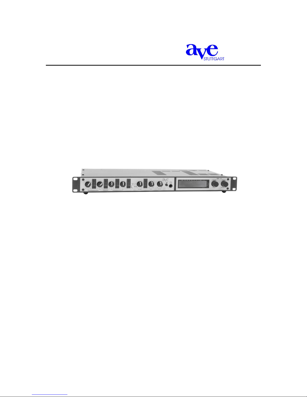
MX 4
Analogue/digital 4-channel mixer
User guide
Table of contents
Page 2

User guide MX-4 page 2
1. Introduction ................................................................................................................. 3
1.1 Security advice ................................................................................................... 3
2. Description of front and rear panel ............................................................................. 4
3 Basic operation of the MX-4 ....................................................................................... 5
3.1 Programmable settings („presets“) .................................................................... 5
3.2 Changing between presets ................................................................................ 5
3.3 Temporarily changing an existing preset ........................................................... 6
4 Extended functions ..................................................................................................... 6
4.1 Programming a new preset (or reprogramming an existing one) ...................... 6
4.2 Programming the MX-4 / The parameter menu ................................................. 7
4.2.1 Preset ........................................................................................................ 8
4.2.2 Parameters ................................................................................................ 8
4.2.3 Config ........................................................................................................ 9
4.2.4 Service ....................................................................................................... 9
4.2.5 Quick reference: Table with all programmable parameters .................... 10
4.3 Internal modifications ....................................................................................... 10
4.3.1 Phantom voltage, microphone/line, high-pass filter ................................ 11
4.3.2 Automatic threshold reduction, transmission matrix ................................ 11
4.3.3 3-band equalizer, compressor/limiter, gain, threshold ............................ 12
4.3.4 Microprocessor Gate control ................................................................... 13
5 Specifications ............................................................................................................ 13
Page 3

User guide MX-4 page 3
1. Introduction
Thank you for choosing the A.V.E. analogue/digital 4-channel mixer MX-4 with four
microphone/line inputs; an outstanding unit that was designed particularly for superior audio
quality in churches.
Each microphone/line input is equipped with a compressor/limiter, 3-band equalizer, as well as
indicators for volume, operating status, and peak, respectively. An automatic processing unit
controls additional functions, such as priority, ducking, number of activated microphones, or the
hold time. Furthermore, a variable graphic equalizer with 48 bands (12 per output) allows an
optimisation for every application. 16 fully parametric equalizers (4 per output), each with an
individually adjustable Q-factor of up to 100, as well as an automatic gain adjustment when
additional microphones are activated provide an optimum feedback elimination.
The MX-4 is equipped with its own software. This makes programming simple and straightforward
– Laptop or PC are no longer required. Up to 20 different sets of settings, so-called „presets“, can
be programmed and can easily be recalled by the user for each occasion as required.
This manual adresses users in sections 2., 3., and 4.1. These parts of the manual deal with
explaining the components of the unit and describe the basic operation. The following part is
addressed to the qualified technical personnel in charge of extended programming and internal
modifications.
1.1 Security advice
Please read the information provided in this manual before starting up the unit.
WITHIN THIS UNIT THERE IS DANGEROUS VOLTAGE PRESENT CONSTITUTING A
RISK OF ELECTRIC SHOCK. DO NOT OPEN THE COVER. INTERNAL
MODIFICATIONS ARE TO BE COMPLETED BY AUTHORIZED PERSONNEL ONLY.
THERE ARE NO USER- SERVICABLE PARTS INSIDE.
The MX-4 is equipped with a power cord for connecting the three-pin inlet connector
of the unit to a 230 V / 50 Hz AC voltage source. Make sure this cable is not damaged.
Do not use any defective or damaged power cords!
Page 4

User guide MX-4 page 4
2. Description of front and rear panel
1. Volume control (for channels 1 – 4): Allows adjustment of the level of the signal sources
connected to the microphone/line inputs (26.). During installation by the technician, the optimal
level will be marked on the unit.
2. Level indicator (for channels 1 – 4): 4-level LED indicator. The maximum level of +5 dB
indicates that the input is overdriven.
3. Gate indicator (green LED; for channels 1 – 4): Optically indicates an activated input. The
processor automatically determines which of the inputs is activated. The level difference at
which an additional microphone is opened, can be set by an internal modification (see section
4.3.4).
4. Channel selector CD/tape: Choose between music rendition via CD or tape. The selection is
indicated by one of the LEDs (5. or 6.). Consumer-level audio equipment such as CD or
cassette player are connected on the back to inputs (24.) or (25.), respectively.
5. LED indicator CD: Music rendition via CD
6. LED indicator tape: Music rendition via tape
7. Volume control for CD/tape
8. Level indicator for CD/tape: A level of +5 dB indicates that the input is overdriven.
9. Low-frequency level control for CD/tape: Controls (9.) and (10.) allow an optimisation of the
sound characteristics of the music rendition.
10. High-frequency level control for CD/tape
11. Volume control for headphones: Input (12.) allows the connection of headphones for
monitoring purposes, the volume of which can be adjusted with this control. Which of the 4
outputs is to be directed to the headphones can be selected in the parameter menu (as
described in section 4.2.3).
12. Connection for headphones
13. LCD display: The bright display contributes to the clear and user-friendly operation of the MX-
4. (The contrast of the display can be adjusted in the parameter menu as described in section
4.2.3.)
14. Volume/Value knob: Rotary encoder with integrated pushbutton. This knob is used, among
others, to set the overall volume or set other values.
15. Preset/Parameter knob: Rotary encoder with integrated pushbutton. This knob is used,
among others, to switch from one preset to another.
Page 5

User guide MX-4 page 5
1 Power connector: Connector for power cord to a 230 V / 50 Hz AC voltage source.
2 Fuse: 315 mA
3 Main on/off switch
4 Output: Output connectors (to power amplifiers, etc.)
5 Direct OUT: Direct output without any signal processing. This output can be used for capturing
and transmitting the ambiance of e.g. a mass to external rooms.
6 Level Direct OUT: Controls the output level of the direct output
7 Link in: Permits multiple mixers to be linked, creating additional inputs.
8 Link out: Output when linking multiple mixers
9 Tape-recording: Phono connectors for tape-recording
10 Tape rendiction: Phono connectors for music rendition via tape
11 CD rendition: Phono connectors for music rendition via CD
12 Microphone/line inputs
Basic operation of the MX-4
3.1 Programmable settings („presets“)
The MX-4 combines numerous integrated functions with very simple operation. Even in
acoustically difficult environments, best results are achieved. So-called „presets“ can easily be
programmed. No less than 20 of these preset slots enable programming for any application
and make them available to the user at the touch of one’s fingertips.
For each preset, the following 3 parameters are programmed:
the master volume
which of the 4 outputs are to be active
a preset name. This way the different settings are immediately distinguishable.
3.2 Changing between presets
Turn the unit on with the main on/off switch in the back.
The welcome message will appear in the display. After a few seconds, it will
disappear again and the settings of the current preset will show up. Below, an
example is given.
Here one can see the current preset
Page 6

User guide MX-4 page 6
name (in this case „Sonntag“) as well as the value of the master volume in percent
(total output volume, here 70%). The bar above the preset name is an analogue
representation of the master volume.
On the right-hand side of the display the four little squares represent the 4 outputs (the
numbers 1 through 4 are written above and below the display). A dot within a square
indicates, that this particular output is active.
Please note: The preset settings can be guarded against accidental changes. In this
„preset protection mode“, changes can only be undertaken by pushing and turning a
knob at the same time.
In order to switch from one preset to another, push the preset knob while turning it
until the desired preset shows up in the display; then let go. Now, all is set for the next
application.
3.3 Temporarily changing an existing preset
Should it become necessary to change the volume of a given preset, push the volume
knob (only necessary in the preset protection mode) while turning it to set the desired
value. This change is only temporary, i.e. once the unit is turned off and back on again,
the original preset is active again.
Should it become necessary to temporarily change the active outputs, then briefly
push both knobs at the same time. By pushing the preset knob, the display will
successively show each output. The respective name of the output will appear (in the
example given below „SchiffV“) as well as a little square next to the corresponding
number of the output. „On“ or „off“ indicate whether the output is active or not. This is
also reflected in the little squares, where a dot in the middle indicates an active output.
Turning the volume knob by one click, you can change the output to „on“ (active) or
„off“ (deactivated). Briefly pushing the volume knob will take you one level back, and in
the display you will see the preset name again with its current settings. These
changes are also temporary, i.e. will only be effective until the unit is turned off and
back on again.
4 Extended functions
4.1 Programming a new preset (or reprogramming an existing one)
This section describes how to programme one of the 20 preset slots, i.e. give a preset
name and select the desired master volume and outputs. In the same fashion, existing
presets can be reprogrammed (as opposed to the temporary changes described in
section 3.3).
First, turn the unit off with the main on/off switch in the back.
Then, turn the unit back on, while pushing both the volume und preset knobs at the
same time. Keep the knobs pushed until the parameter menu appears (see below).
The four items „preset“, „parameters“, „config“, and „service“ appear.
Briefly push the preset knob. The first preset will appear („preset 1“ in case no preset
Page 7

User guide MX-4 page 7
name has been given so far).
In case you wish to choose a different preset slot, briefly push the volume knob twice.
That way you move back to the main menu and can chose a different preset by
pushing and turning the preset knob.
A yet unused preset slot can be identified by the fact that it does not yet have given
preset name, but merely „preset“ and a number (e. g. „preset 12“).
Briefly push both knobs at the same time. Again the parameter menu shows up.
Push the preset knob. Now you can determine the preset name. The cursor will blink
under the first character.
By turning the volume knob, the following letters, numbers, and special characters will
appear in this order: A-Z, Ä, Ö, Ü, a-z, ä, ö, ü, 0-9, space, ! „ # $ % & ’ ( ) * + , - . /
Pushing the preset knob will confirm the current character und move the cursor one
position to the right. Now you can set the next character.
Wenn you’ve filled in the preset name, turn the preset knob one click to the right to
now determine the master volume for this preset. Set the value by turning the volume
knob. The values range from 0 to 100%. The corresponing value in dB is given in
brackets.
Now turn the preset knob again one click to the right in order to determine the outputs
for this preset.
When pushing the preset knob, the 4 outputs will appear one after the other with their
respective names. „On“, as well as a dot in the little square, indicate that this output is
active. By turning the volume knob one click, the shown output can bei either activated
or deactivated.
Now the programming for this preset is complete. By pushing the volume knob, you
will exit the programming mode. You will be asked whether you would like to „Save
changes?“. Pushing the volume button indicates „yes“ and your changes will be saved
( „Saving … do not interrupt“). Pushing the preset knob indicates „no“ and the
display will show „Changes discarded!“.
,
THE FOLLOWING MODIFICATIONS ARE TO BE PERFORMED
BY QUALIFIED AUDIO TECHNICIANS ONLY.
4.2 Programming the MX-4 / The parameter menu
Functions and settings in the parameter domain should be changed by qualified personnel
only. The only exception is the programming of a new preset as described in section 4.1.
The digital control boasts the great advantage of the programmability of various functions.
In this parameter menu, not only the presets are programmed, but among others, the
equalizers and the parameters for feedback elimination are set. In fact, the entire
programming of the MX-4 is done here with menu-driven user guidance and merely two
knobs. No PC or Laptop are required.
In oder to enter the parameter menu (and therefore the programming mode), first turn
the unit off.
Then, turn it back on again while pushing both knobs (volume and preset) until the
parameter menu with its four items preset, parameters, config, and service appear.
By turning the preset knob, you can change from one menu item to the next which is
indicated by a small triangle.
By pushing the preset knob, you chose the respective item from the menu.
General comments on programming the MX-4:
Page 8

User guide MX-4 page 8
Turning the preset knob one click to the right will always bring you to the next item of a
menu, i. e. to the next parameter to be programmed. This knob is therefore also
marked „parameter“. For simplicity, we will continue to name this knob the preset knob.
Changing a value or character is always done by turning the volume knob. This knob
is therefore also marked „value“. However, here too for simplicity, we will stay with the
name of volume knob.
These knobs are so-called dynamic rotary encoders, meaning that when slowly
turning one of them, the value will change in small increments whereas turning a knob
by the same amount more quickly will change the value superproportionally faster.
This enables a fast but precise setting of the desired values.
By pushing the volume knob, you will go up one level in the menu hierarchy.
Whenever you have changed any parameter, you will be asked whether you would
like to „Save changes?“. Pushing the volume button indicates „yes“ and your changes
will be saved ( „Saving … do not interrupt“). Pushing the preset knob indicates
„no“ and the display will show „Changes discarded!“.
The following 4 sections will describe the programming possiblities of the 4 menu
items. For quick reference, there is a table of all programmable settings at the end (in
section 4.2.5).
4.2.1 Preset
Preset name: Determine the name for a given preset. The procedure is described in
detail in section 4.1.
Preset master molume: Setting the master volume for a given preset.
Preset output: Choose the desired outputs for a given preset. The procedure is
described in detail in section 4.1.
4.2.2 Parameters
Level: Determine the level for each output. Set the desired value by turning the
volume knob. Pushing the preset knob will bring you to the next output. With this
indivudual level setting, you will achieve an optimal balance of the outputs which
remains even when changing the master volume.
Delay: Dalay time for the outputs 3 and 4 only. It can be set in 1-meter increments
and the corresponding delay time is given in milliseconds (calculated according to a
speed of sound of 343 m/s, corresponding to a room temperature of 20 °C). Here, too,
pushing the preset knob will move you from one output to the next.
Graph EG: Set the level of the 12 bands of the graphic equalizer for each of the 4
outputs (see picture below). By turning the preset knob, you will move to the next
frequency; again by pushing it, you will move to the next output. Please note: The
variable graphic equalizer VariGraph allows you to choose the frequencies of the 1st
and 12th band of the equalizer for an optimal adjustment to each and every application.
These frequencies can be set under the item „config“ as described in section 4.2.3.
The frequencies of the 10 bands in between are calculated automatically.
Param EQ 1 Freq: Set the 1st frequency of the fully parameteric equalizers (range: 20
Hz to 20.45 kHz). Here, too, the value is set with the volume knob. Pushing the preset
knob will bring you to the next output, so you can set the first frequency for each
output.
Param EQ 1 Gain: Set the gain of the 1st band (range: +18 to -44 dB). Between +18
and -20 dB very fine 0.5 dB increments are possible.
Page 9

User guide MX-4 page 9
Param EQ 1 Q: Set the Q-factor for the 1st band (range: 0.2 to 100; logarithmic
increments 0.2, 0.22, 0.25, 0.28, 0.32, etc.). The high Q-factors enable extremely
narrow-band notch-filters for ideal feedback elimination.
Param EQ 2-4 Freq: Proceed as described above for bands 2, 3, and 4.
Param EQ 2-4 Gain: Proceed as described above for bands 2, 3, and 4.
Param EQ 2-4 Q: Proceed as described above for bands 2, 3, and 4.
Limiter: Can be indivudually set for each output. By pushing the preset knob, you can
chose the output; turning the volume knob by one click, you can turn the limiter either
„on“ or „off“.
By pushing the volume knob you return back to the parameter menu. In case you
have canged any parameters, you will be asked whether you would like to save them.
4.2.3 Config
Graph EQ Band 1: Set the frequency of the 1st band of the graphic equalizer. The
frequency value is set by turning the volume knob.
Graph EQ Band 12: Set the frequency of the 12th band of the graphic equalzer. A
minimum distance of approximately 2 octaves needs to be maintained between the 1st
and 12st band. The unit will prevent a smaller distance to be set.
Monitor / VU Out: Selection of one of the 4 outputs for monitoring via headphone. On
the left side next to the display there is a headphone connection that can be used for
monitoring purposes. The output chosen here is also the one corresponding to the VU
meter in the display. By turning the volume knob, you can chose the desired output.
LCD contrast: Set the contrast of the LCD display from 0 to 50 for an optimal
readability.
Vol/Preset protect: The protection of the settings is such that changes (e. g.
changing between presets or temporary volume changes) can only be performed
while pushing and turning the knobs at the same time. This is intended to safeguard
the settings from accidental changes. If this protection is turned off, changes can be
made by simply turning the knobs without pushing them. Turning the volume knob by
one click either enables or disables the protection.
Welcome screen Line 1: Set the first line (16 characters) of the welcome text that
shows up when powering up the unit. The cursor will blink under the first character. By
turning the volume knob, the following letters, numbers, and special characters will
appear in this order: A-Z, Ä, Ö, Ü, a-z, ä, ö, ü, 0-9, space, ! „ # $ % & ’ ( ) * + , - . /
Pushing the preset knob will confirm the current character und move the cursor one
position to the right. Now you can set the next character.
Welcome screen Line 2: Set the second line (16 characters) of the welcome text that
shows up when powering up the unit.
Output 1 Name: Determine the name of the first output. 8 characters are available for
this name (e.g. nave, gallery, etc.)
Output 2 Name
Output 3 Name
Output 4 Name
4.2.4 Service
Firmware: Displays the current firmware version of the unit.
Page 10

User guide MX-4 page 10
4.2.5 Quick reference: Table with all programmable parameters
Where is which parameter set?
The following table lists the parameter menu with its items and parameters:
Item
Parameter
Description
Preset
Preset name
Name of the preset
Preset master volume
Master volume of the preset
Preset output
Choice of active outputs
Parameters
Level
Level of each output
Delay
Delay times for outputs 3 and 4
Graph. EQ [1st. frequency]
Level of 1st band of the graphic
equalizer; settable vor each
output
…
…
Graph. EQ [12st frequency]
Level of 12th band of the graphic
equalizer; settable for each output
Param. EQ 1 Freq
Frequency of the 1st parametric
equalizer; settable for each output
Param. EQ 1 Gain
Gain of the 1st parametric
equalizer; settable for each output
Param . EQ 1 Q
Q-factor of the 1st parametric
equalizer; settable for each output
… [same for the other
parametric equalizers]
Limiter on/off
Set limiter individually for each
output
Config.
Graph EQ Band 1
Frequency of the 1st band of the
graphic equalizer
Graph EQ Band 12
Frequency of the 12th band of the
graphic equalizer
Monitor / VU Out
Select output for headphone
connection (monitoring) and VU
meter
LCD Contrast
Contrast of the LCD display
Vol/Preset Protect
Rotery encoder protection on/off
Welcomescreen Line 1
1st line of welcome screen
Welcomescreen Line 2
2nd line of welcome screen
Output 1 Name
Name of 1st output
Output 2 Name
Name of 2nd output
Output 3 Name
Name of 3rd output
Output 4 Name
Name of 4th output
Service
Firmware
Firmware version
4.3 INTERNAL MODIFICATIONS
Page 11

User guide MX-4 page 11
BEFORE OPENING THE UNIT, TURN IT OFF AND
REMOVE THE POWER CORD.
ONLY THEN REMOVE THE SIX SCREWS AN THE COVER.
4.3.1 Phantom voltage, microphone/line, high-pass filter
These modifications are performed by means of jumpers. Within the MX-4, there are two
groups of jumpers for each of the four outputs.
The following image shows the upper group of 4 jumpers each per channel.
Their functions are indicated on the label. In order to realise the function on the left, short
the respective jumper.
High-pass filters for each of the 4 microphone/line inputs, 40 Hz/ 100 Hz. For the use
of microphones, the jumpers should be set to 100 Hz. This high-pass (low-cut) filter
reduces low-frequency vibrations and compensates for the so-called proximity effect
(the booming sound often associated with close pick-up).
Phantom power: +48 V. This function is very usful for e. g. condensor microphones,
as most of the latter require phantom power.
Selection whether microphone or line input
4.3.2 Automatic threshold reduction, transmission matrix
Page 12

User guide MX-4 page 12
The following image shows the second group of jumpers: 6 jumpers for each of the four
channels. (The numbers 1 through 6 denote the six potentiometers for each channel.
Their functions will be described in section 4.3.3)
THD: low noise threshold, on/off. A noise gate, determining the response sensitivity of
the microphones, can be either enabled or disabled here. (The threshold itself is
adjusted with potentiometer no. 3, see section 4.3.3). Actually, this analog threshold is
quite redundant, as this the response sensitivity is controlled in a much more precise
fashion by the automatic processor.
Automatic threshold reduction by the processor when using multiple microphones,
on/off: In order to achieve a maximum gain-before feedback and signal quality, only
those microphones are activated that receive an actual (intended) signal. In parallel,
there is an automatic gain adjustment as additional microphones are activated. This
automatic can be either enabled or disabled by this jumper.
Selection for each of the four inputs to which outputs (OUT 1 through OUT 4) they are
to be transmitted. By default, each of the inputs are set to all four outputs.
4.3.3 3-band equalizer, compressor/limiter, gain, threshold
The six potentiometers for each channel have the following functions
1. Compressor/limiter: The output limiters prevent distortion during loud peaks. All
signals below the set threshold are not affected whereas those above are compressed.
This keeps the devices connected to the MX-4 from becoming overloaded and
prevents distortion and clipping.
2. Gain: Adjusts the amplification of the channel to the level of the input signal.
3. Threshold control: Adjusts the response sensitivity of the microphone. The here
adjusted threshold can be disabled if necessary by a jumper (see THD in section
4.3.2).
4. High frequencies: 3-Band equalzer for an optimal adaption of the microphone to the
speaker; 12 dB at 10 kHz
5. Mid frequencies: 12 dB at 100 Hz
1
2
3
4
5
6
Page 13

User guide MX-4 page 13
6. Low frequencies: 12 dB at 70 Hz
4.3.4 Microprocessor Gate Control
Continous level monitoring of 8 input channels by RISC microprocessor
Level compare accuracy better than ±2 dB
Channel on attack time less than 10 ms
Channel on hold time 256 ms (default) / 512 ms, selectable via switch
Last On (default) / Channel 1 On, selectable via switch, hysteresis 6 dB
Simultaneous active channels: none (default) / 3+4 selectable via switch
Switch 1
Hold time
Off
256 ms
On
512 ms
Switch 2
Active channel
Off
Last channel
On
Channel 1
5. Specifications
DSP structure
4 channels with completely independent 24 bit / 96 kHz digital audio processing output levels
Output level and master volume
Independent setting of output level for each channel: +12 to - dB (very good resolution with precise 0.5
dB increments from +12 to -20 dB)
Common setting for overall output level (master volume): +10 to -0 dB (precise 0.5 dB increments from -
10 to -20dB)
Delay
For channels 3 and 4
Delay: 0 to 680 ms (0 to 233 meters). Settings: in meters (1-meter increments, calibrated to an acoustic
velocity of 343 m/s, according to a room temperature of 20°C)
Variable graphic equalizer (VariGraph EQ)
48 bands (12 per output)
Switch 3
Switch 4
Simultaneously addresed microphones
Off
Off
1 (input 1 – 8)
Off
On
2 (input 1 – 8)
On
Off
3 (input 1 – 8)
On
On
4 (input 1 – 8)
Page 14

User guide MX-4 page 14
VariGraph: frequencies for the bands 1 and 12 can be arbitrarily chosen (for each channel, minimum
spacing approx. 2 octaves), Q-factors as well as all intermediate bands are automatically calculated
accordingly (allows for an optimal adaption of the equalizer to each application)
Fully parametric equalizer
16 bands (4 per channel)
Frequency: 20 Hz to 20.45 kHz (each band), very good resolution of 96 steps per octave
Gain: +18 to -44 dB (each band), fine 0.5 dB steps from +18 to -20 dB
Q-factor: 0.2 to 100 (logarithmic scaling 0.2, 0.22, 0.25, 0.28, 0.32, etc.), this permits extremely
narrowband notch filters for feedback elimination without loss of sound quality
Limiter
Can be enabled separately for each channel, reliably protects the sound system from sudden,
unexpected increases in signal level that can lead to amplifier clipping or loud-speaker damage
Preset (set of programmable parameters)
Available number of presets: 20
Preset parameters: master volume, output on/off, preset name
VU meter and master volume indicator
VU meter for one channel (freely selectable), headphone connection (for monitoring) renders the
selected channel
VU meter range: 0 to -50 dB, 14 bars (0 dB corresponds to the peak output level of the DSP output)
Volume bar: renders graphic representation of the master volume
User Interface
Display: 2 lines of 20 characters each, user input via two rotary encoders with integrated pushbuttons
All settings are adjusted directly on the instrument by menu-driven user guidance (i.e. without external
PC or laptop)
Separate parameter domain (EQs, delays, etc.) and user domain (master volume, preset, channel on/off)
The parameter domain is safeguarded against unauthorised access, the safety mechanism works
without a password (eliminates the problem of forgotten passwords)
The user domain can be protected against accidental change of settings
Freely definable welcome message upon power-up (2 lines of 16 characters each)
For each channel a name can be freely defined (up to 7 characters) which appears in all relevant menus
on the display
DSP internals
ADC / DAC resolution and sampling rate: 24 bit, 96 kHz
DSP internal accuracy: 48 bit, entire data path
DSP audio clock frequency: 96 kHz, entire data path (thus, EQs are very precise at high frequencies)
DSP internal overload reserve: 48 dB (renders a DSP internal overload in conventional applications
virtually impossible)
Line
Maximum level: 100 mV (max. gain), 3 V (min. gain)
Gain: 8 mV (-40 dBu) / 430 mV (-5 dBu)
Microphone
Maximum level: 2.5 mV (max. gain), 200 mV (min. gain)
Input impedance: 0.6 mV (-62 dBu) / 45 mV (-25 dBu) 1 dB
CMMR: > 60 dB at 1 kHz
THD level: 10 dB
Hi-pass-filter: 100 Hz, 6 dB/oct
Phantom power: + 48 V
Tape/CD
Impedance tape: 16 k
Impedance CD: 28 k
Input sensitivity tape: -12 dBu
Input sensitivity CD: -7 dB
Outputs
Output impedance OUT 1, 2, 3, 4: 140 balanced; 70 unbalanced
Page 15

User guide MX-4 page 15
Output level Out 1, 2, 3, 4: 0 dBu (with master volume at 82 %)
Output level OUT 1, 2, 3, 4: +9 dBu (with master volume at 100 %)
Output impedance Direct-OUT: 140 balanced; 70 unbalanced
Output level Direct-OUT: +6 dBu (variable potentiometer)
Output impedance REC: 70 unsymmetrisch
Output level REC: 0 dBu
Linking multiple mixers:
Impedace Link IN: 10 k unbalanced
Input sensitivity: -6 dBu
Output impedance Link OUT: 100 unbalanced
Output sensitivity: -6 dBu
Headphones
Impedance headphones: stereo 8 / 32 / 100 / 600
Output power headphones: 150 mW / 180 mW / 85 mW / 20 mW
Processor
Hold time: 8 ms / 256 ms / 512 ms / 768 ms (settable with internal dip-switch)
Pegelunterschied: 0 dB / 3 dB / 6 dB / 10 dB (settable with internal dip-switch)
3-band equalizer
High-frequency: 12 dB at 10 kHz
Mid-frequency: 12 dB at 700 Hz
Low-frequency: 12 dB at 70 Hz
Frequency response
-3 dB for CD: 50 Hz – 20 kHz
-3 dB for microphone: 100 Hz – 16 kHz
Noise
Noise level Direct-OUT, loaded, 20 Hz – 20 kHz, potentiometer at 0: -97 dBu
Noise level OUT 1, loaded, 20 Hz – 20 KHz, master volume at 0: -92 dBu
Noise level OUT 1, loaded, 20 Hz – 20 kHz, master volume at 82 %: -88 dBu
General
Operating voltage: 230 V~, 50-60 Hz
Power consumption: 30 W
Overall dimensions: B x T x H = 483 mm W x 208 mm D x 44 mm H
Mountable in 19“ rack
Net weight: approx. 4 kg
Page 16

User guide MX-4 page 16
Notice
ALL AVE mbH DESIGN SPECIFICATIONS, FILES, DRAWINGS, TABLES, LISTS,
AND OTHER DOCUMENTS ARE BEING PROVIDED “AS IS.”
AVE mbH MAKES NO WARRANTIES, EXPRESSED, IMPLIED, STATUTORY, OR
OTHERWISE WITH RESPECT TO THE MATERIALS, AND EXPRESSLY
DISCLAIMS ALL IMPLIED WARRANTIES OF NONINFRINGEMENT,
MERCHANTABILITY, AND FITNESS FOR A PARTICULAR PURPOSE.
Information furnished is believed to be accurate and reliable. However, AVE mbH
assumes no responsibility for the consequences of use of such information or for any
infringement of patents or other rights of third parties that may result from its use. No
license is granted by implication or otherwise under any patent or patent rights of
AVE mbH. Specifications mentioned in this publication are subject to change without
notice. This publication supersedes and replaces all information previously supplied.
AVE mbH products are not authorized for use as critical components in life support
devices or systems without express written approval of AVE mbH Corporation.
Trademarks
AVE mbH and the AVE logo are trademarks or registered trademarks of AVE mbH in
the Germany and other countries. Other company and product names may be
trademarks of the respective companies with which they are associated.
Copyright
© 2015 AVE mbH. All rights reserved.
Consulting • Planning • Developing • Assembly of electroacoustic sound systems
AVE GmbH • Gustav-Rau-Straße 6 • 74321 Bietigheim-Bissingen • Germany
Phone +49 (0)7142 78879-0 • Fax +49 (0)7142 78879-18
info@ave-stuttgart.de • www.ave-stuttgart.de
 Loading...