

Page 1

OPERATION MANUAL
June 15, 2006
ATM TCPIP Interface
TT
TT
T
CPIP232CPIP232
CPIP232CPIP232
CPIP232
Page 2

TCPIP232 Connections
There are 2 kinds of connection for TCPIP232
1. Stand alone with Digital Video Recorder
This connection will inteface directly to DVR which supported Text Insertion. This insertion will
interface via RS232C only from TCPIP232 rear panel.So Please consult your DVR manual or contact
DVR manufacturer.
2. VSSI-pro Interface
VSSI-Pro has also supported text insertion and programmable gray scale and background of text
inesertion. User are able to define the ATM IP Address via Onscreen programming on VSSI-Pro Menu.
Introduction TCPIP232 ATM Interface.
TCPIP232 ATM Interface is designed to capture ATM transactions on ATM LAN system then
convert caputered transactions to serial port to interface with VSSI-Pro (ATM Serial Interface)
or Digital Video Recorder (DVR) which supports text insertion and overlays trasaction information to video.
PAGE 2
Figure 1. S tand alone connection
ATM
Camera
Rounter/Network
CAT-5
CAT-5
Video Coaxial
Video Coaxial
Serial
DVR
TCPIP232
Monitor
Figure 2. VSSI-Pro Interface
Page 3
TCPIP232 Hardware Configuration:
TCPIP232 hardware operation depends on your network connection. TCPIP232 is able to operate
with HUB and Network Switcher. There are 2 hardware configurations:
1. Mirror Mode
This Mode supports HUB and Programmable Network Switchers. The user needs to provide a
port for TCPIP232 to capture A TM transactions on the HUB and needs to mirror the ATM LAN port
for TCPIP232 port to capture data. This kind of switcher we called “ programmable network switcher”
which is very expensive.
2. Tapping Mode.
The T apping mode supports HUB and T ypical Network Switcher . T appping Mode captures
A TM transactions by tapping receiving data at the A TM only . So HUB and Switch will not see
TCPIP232 as a network device. see Figure 3
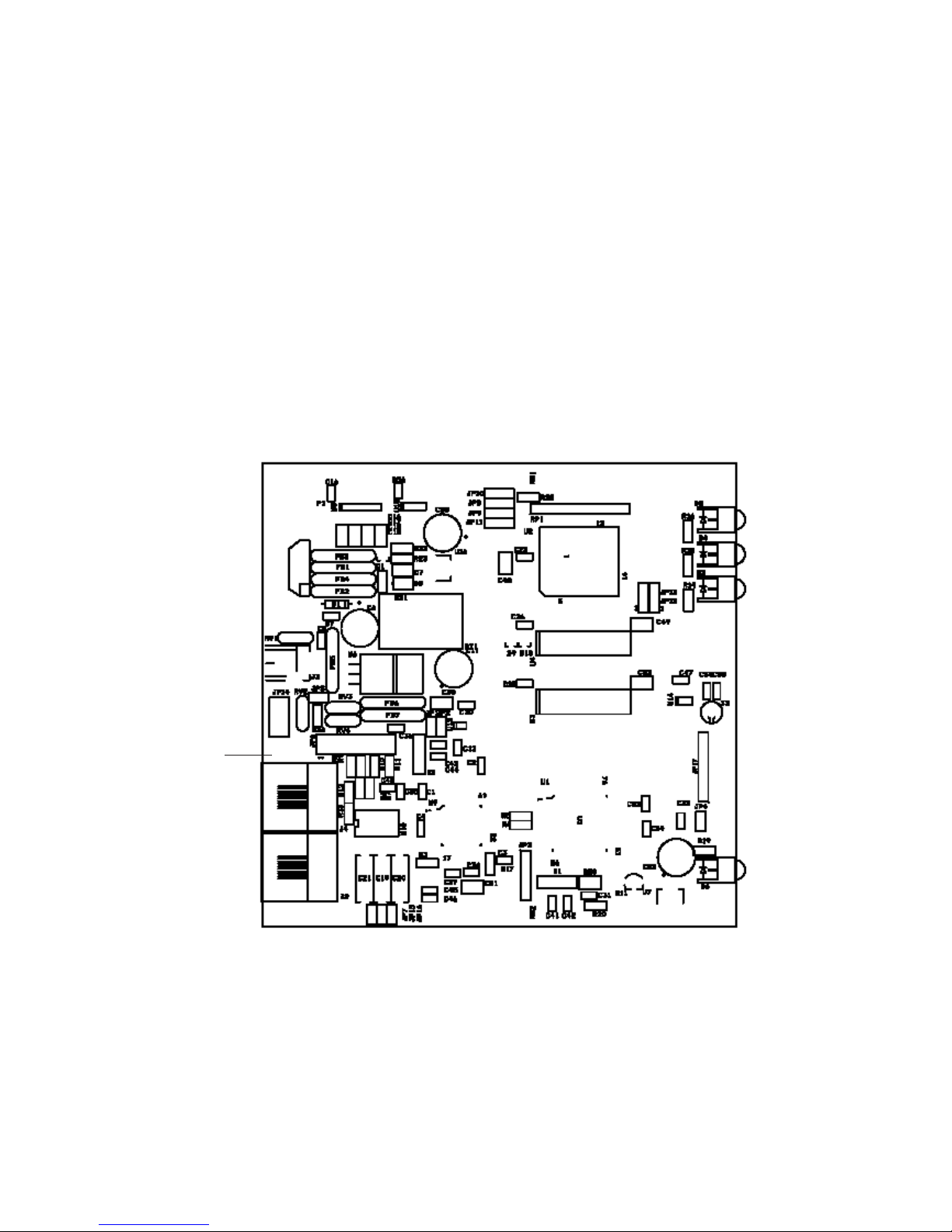
Figure 3. TCPIP232 Hardware Silkscreen
JP7, JP15 JP16
JP6
1
Tapping Mode Setup. (This is defualt from manufacturer)
1. Close JP7 and JP15. Open JP16. (Lifted up Pin of C20 on Old PCB)
2. JP6 Close PIN5-6, PIN11-12
Mirror Mode Setup
1. Close JP7, JP15, JP16 ( Need to install C20)
2. JP16 Close Pin1-2, Pin3-4, Pin5-6,Pin7-8,Pin9-10,Pin11-12,Pin13-14,Pin15-16
2
PAGE 3
Page 4

TCPIP232 Setups
The user must be careful to unplug the LAN cable from the A TM. The A TM has the
protection when there is no comunication between the A TM and Host Server in limited
time your A TM will be of fline automatically . This peroid is called the “A TM T ime Out’. This
time out depends on your A TM system. It is approximately 6-10 seconds.
Stand alone Setup:
Connect the PC/DVR Cable which comes from the TCPIP232 adapter to your
laptop. Power up your TCPIP232 and your laptop and run TCPIP232 Setup to program the
IP Address of the TCPIP232. This IP address will be the same as the A TM machine. Unplug your PC/DVR Cable from your laptop and plug it to your DVR Com port. Now your
need to program your DVR to display text insertion.
VSSI-Pro Setup
Connect the TCPIP232 adapter to the VSSI-Pro with the provided cable, connect video,
A TM LAN and power up both units.
1. Enter the VSSI-Pro Main Menu by simultaneously pressing and holding the DOWN and
UP while then press and releasing RESET Button. The main menu will be displayed as
below. So move cursor to A TM Select by press UP or DOWN button. Press SET to enter
the A TM Select Menu.
MAIN PROGRAMMING MENU
* ATM SELECT
SCREEN SETUP
TEXT DISPLA Y
COMMUNICA TION
EXCEPTION REPORT
ALARM OUTPUTS
TEST/DEMO MODE
DWN/UP LOAD SETUP
HELP
2. On A TM Select Menu, Move cursor to TCPIP Interface then press SET to enter
SDLC
BSYNC
ASYNC
CAMERA PORT
JOURNAL PRINTER
*TCPIP INTERF ACE
CUSTOM
EXIT
3. The Menu in TCPIP Interface will be displayed as below:
*TCPIP FORMA T I
TCPIP DEBUGING
EXIT.
PAGE 4
Page 5

TCPIP232 LED Indicators
GREEN POWER TCPIP-232 Power Status
RED RECEIVE TCPIP-232 Receive Data from A TM
GREEN LINK ATM Status, On = Ready/OFF = Not ready
YELLOW SPEED OFF = 10Mbps, On = 100Mbps Ethernet
Cables and Pin assignments:
TCPIP232-PC/DVR Cable
This is RS232 Cable. User uses to programming IP Address on TCPIP232 and
then remove and pluge to DVR to insert ASCII text on V ideo.
TCPIP232 Port PC/DVR Port
DB9 Female DB9 Female
Pin-5 (GND)--------------------------------------------------Pin-5 (GND)
Pin-2(RXD)---------------------------------------------------Pin-3 (TXD)
Pin-3(TXD)---------------------------------------------------Pin-2 (RXD)
TCPIP232-VSSI-Pro Cable
This is also RS232 Cable. User users use to interface with VSSI-Pro. This cable
also provided reached alarm cable to interface with alrm systems. and also included Serial
output to connect with DVR to get text insertion. This kind of text insertion will help user to
used it to serach video by seraching from T ext . This feature is for A VE DVR only .
TCPIP232 VSSI-Pro DVR
Pin-5(GND)-------------------------Pin-5(GND)----------------------------Pin-5(GND)
Pin-2(RXD)-------------------------Pin-3(TXD)
Pin-3(TXD)-------------------------Pin-2(RXD)
Pin-8(CTS)-----------------------------Pin-2(RXD)
Pin-1(Alarm)
PAGE 5
4. Select TCPIP Format I to enter and Change the IP Address the same as A TM’s IP
Address. Example, if the ATM’ s IP address is 192.168.0.141 So the address on TCPIP-
232 Adapter this menu as:
*IP ADDRESS 1 192
IP ADDRESS 2 168
IP ADDRESS 3 0
IP ADDRESS 4 141
EXIT
1. Exit off to return to the main menu then press RESET button to operation mode.
2. T est you transaction on A TM to verify VSSI-Pro and TCPIP-232 Adapter’s Operation.
Page 6

LIMITED W ARRANTY
(Terms and Conditions)
For 2 Years from the date of shipment, Seller warrants to Buyer that the Product is free from defects in
material or workmanship under normal use and service. Equipment manufactured by other than Seller
but furnished by Seller carries the same warranty to Buyer as Seller receives from the other manufacturer,
notwithstanding any provision to the contrary. If Buyer has specified a particular manufacturer’s product
which is not the brand standardly supplied by Seller, Buyer shall look only to the other manufacturer’s
warranty and Seller shall not warrant such item.
EXCLUSIONS. Seller’s warranty does not cover the following:
(1) in-transit damage claims, improper handling by carrier or post office (Note: only the consignee of
the shipment can file a claim with the common carrier)
(2) damages caused by incorrect use, modification, carelessness, improper storage, hostile operat-
ing conditions, or unauthorized service, installation or repairs without proper training from the
Seller
(3) damages caused by fire, flood, lightning, collision, acts of God or other events beyond the
control of Seller
(4) products or parts thereof that have had serial numbers removed, altered or defaced
(5) products returned without an RMA number and sales or delivery receipt showing the date of
original purchase
(7) use of components that do not meet Seller’s specifications
(9) external parts such as cabinets or keypads
(10) periodic maintenance and adjustments resulting from normal use
WARRANTIES EXCLUDED, SELLER EXPRESSLY DISCLAIMS AND EXCLUDES ANY EXPRESS OR
IMPLIED WARRANTY OR MERCHANTABILITY OR FITNESS FOR A PARTICULAR PURPOSE WHICH
EXCEEDS OR IS INCONSISTENT WITH THE WARRANTY HEREIN EXPRESSLY SET FORTH.
NON-WARRANTY CLAIMS. In the event Buyer makes a warranty claim and Seller’s warranty does not
apply, Buyer shall reimburse Seller for all reasonable expenses incurred by Seller in diagnosing the installation/repair problem.
BUYER’S EXCLUSIVE REMEDIES. If the Product supplied shall fail to conform to the contract or any
applicable warranty, Buyer shall immediately notify Seller of such condition and afford Seller a reasonable
opportunity to inspect said Product. Seller shall, at its option, either repair or replace such nonconforming
Product. Seller shall not be responsible for labor charges for removal or installation of such equipment or
material or charges for transportation, handling and shipping except as provided in Seller’s written service
policy. No Product shall be returned without Seller’s prior written consent.
SELLER SHALL NOT BE LIABLE FOR ANY SPECIAL, DIRECT INCIDENTAL OR CONSEQUENTIAL
DAMAGES OF A COMMERCIAL NA TURE ARISING OUT THE USE OF OR INABILITY T O USE SELLER’S
PRODUCT BY REASON OF THE FACT THA T SUCH PRODUCT DOES NOT CONFORM TO THE CONTRACT OR TO ANY EXPRESS OR IMPLIED WARRANTY. SELLER’S MAXIMUM LIABILITY SHALL BE
LIMITED TO THE COST OF REPAIR AND/OR REPLACEMENT OF THE PRODUCT CLAIMED TO BE
DEFECTIVE OR NONCONFORMING, SUBJECT TO SELLER’S RIGHT OF REMOVAL AND RETURN
OF PRODUCT.
All of the foregoing constitute Buyer’s sole and exclusive remedy and Seller’s sole and exclusive liability for
supplying nonconforming or defective Product.
PAGE 6
Page 7

RETURNS. AVE products are fully inspected and carefully packed to ensure you are delivered a quality
product in good condition. If you are not fully satisfied with our product, returns of standard stocking items with
no restocking fee can be made within thirty (30) days of invoice to Buyer. All such returns must have prior
consent of Seller by obtaining an RMA number and must include the sales or delivery receipt showing the date
of original purchase and be in an unused condition contained in its original packaging. Any other returns must
have prior written consent of Seller and are subject to a restocking fee of fifteen percent (15%) and freight
charges.
RMA NUMBER. The RMA (Return Material Authorization) number must be obtained by contacting Seller prior
to the shipment of the the product for return. The RMA number is valid only for 15 days from the date of issue.
The RMA number must be clearly displayed on all shipping labels.
PAGE 7
Page 8

ASIA
AVE (Thailand) Co., Ltd.
217/4 Crystal Garden
Soi 4 (Nanatai), Sukhumvit Rd.
Klongtoey , Klongtoey
Bangkok, 10110 Thailand
Tel: 662-656-8231
Fax: 662-656-9554
Email: ave@avethailand.com
www.avethailand.com
NORTH AMERICA
A VE USA
2000 West Governors Circle, Suite E
Houston, Texas 77092
Tel: 281-443-2300
Fax: 281- 443-8915
Email: aveus@ave-us.com
www.americanvideoequipment.com
WESTERN EUROPE
AVE Multiview
Unit 1C, The Potteries,
Woodgreen Road, Waltham Abbey
Essex, EN9 3SA, UK
Tel: 440-870-770-9323
Fax: 440-870-770-9363
Email: ave-uk@multiview .net
www.multiview.net
 Loading...