

Page 1
User guide AMV 2125-DSP page 1
VertriebsEntwicklungsgesellschaft
mbH
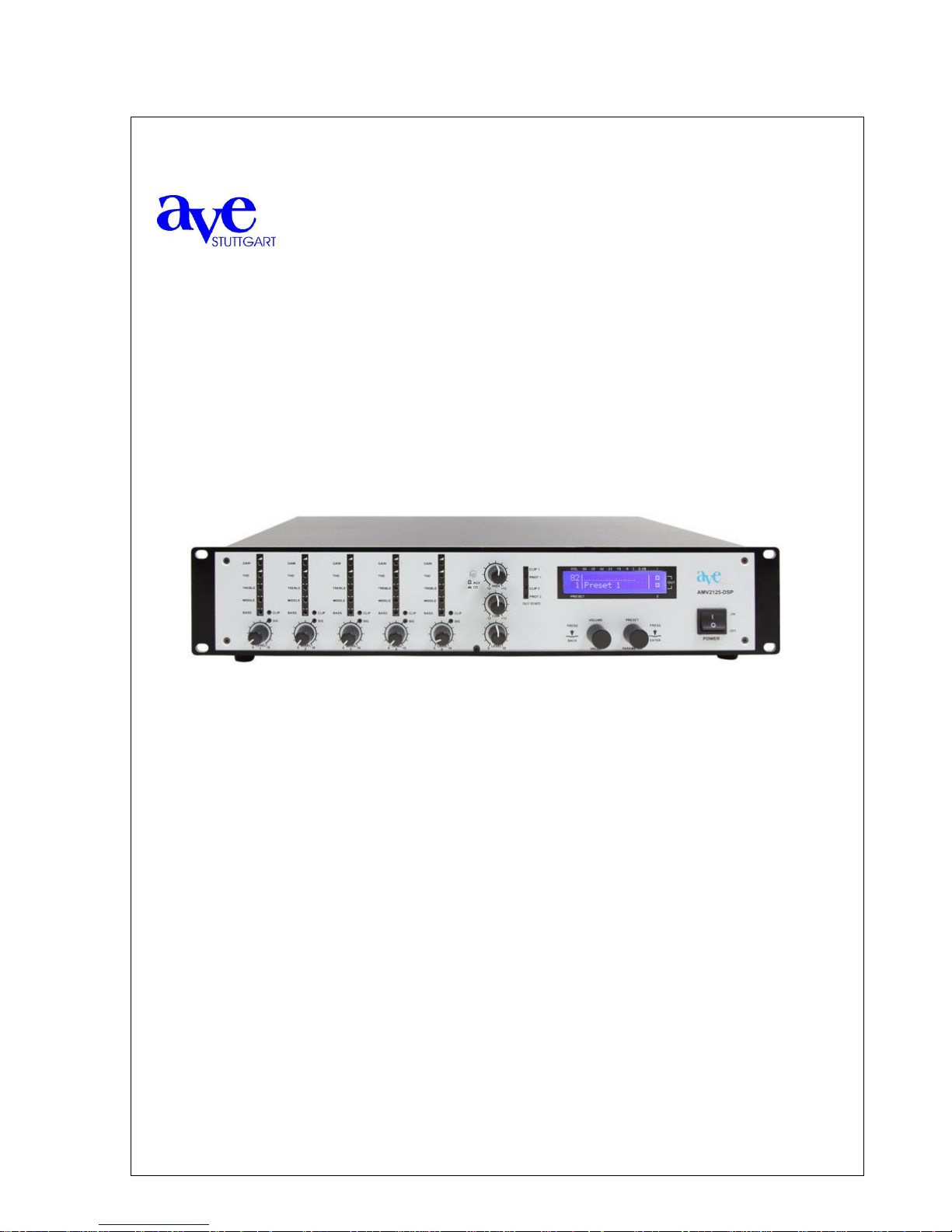
AMV 2125-DSP
Automatic mixing amplifier
User guide
Table of contents
1. Introduction
1.1 Security advices
2. Description of components and functions
3. Basic operations
3.1 Microprocessor gate control
3.2 Programmable settings („Presets“)
3.3 Use of different pre-adjustments („Presets“)
3.4 Changing existing preset-adjustments
4. Extended Functions
4.1 Adjust new presets
4.2 Parameter-menue
4.2.1 Preset
4.2.2 Parameters
4.2.3 Configuration
4.2.4 Utility
4.3 Index of all programmable parameters
5. Tecnical datas
Page 2

User guide AMV 2125-DSP page 2
1 Introduction
Thank you for choosing the A.V.E. automatic mixing amplifier AMV 2125-DSP with five
microphone/line inputs and a switchable CD/Aux.-Input. It was designed particularly for superior audio
quality in churches as well as other utilizations with acoustically difficult room proportions. It’s possible
to achieve an optimized acoustic pattern every time.
Each microphone/line input is equipped with a Gain-controller, a THD-controller, 3-band equalizer, as
well as indicators for volume, operating status, and peak, respectively. Additionally it’s equipped with a
2-channel-DSP, with a 31-band (Terzband) graphic equalizer per output, 6 fully parametric equalizers
per output, each with an individually adjustable factor of 0,2 up to 100 to provide an optimum feedback
elimination. Therefore the AMV 2125-DSP is qualified to sound each kind of critical spaces.
The AMV 2125-DSP is equipped with its own software. This makes programming simple and
straightforward – Laptop or PC are no longer required. Different sets of settings, so-called „presets“,
can be recalled by the user. They can be programmed for each occasion as required.
This manual adresses users in sections 2., 3., and 4.1. These parts of the manual deal with explaining
the components of the unit and describe the basic operation. The following part is addressed to the
qualified technical personnel in charge of extended programming and internal modifications.
1.1 Security advices
Please read the information provided in this manual before starting up the unit.
WITHIN THIS UNIT THERE IS DANGEROUS VOLTAGE PRESENT CONSTITUTING A RISK OF
ELECTRIC SHOCK. DO NOT OPEN THE COVER. INTERNAL MODIFICATIONS ARE TO BE
COMPLETED BY AUTHORIZED PERSONNEL ONLY.
The AMV 2125-DSP is equipped with an approved power cable. At one end there is a three-pole
mains connection socket (rubber connector) and at the other end a CE-standardized Schuko-socket to
connect to a 230 V/ 50 Hz voltage source. Please take care, not to damage these power cords. Do not
use any defective or damaged power cords!
advice • planning • development • assembly of sound systems
AVE GmbH • Gustav-Rau-Straße 6 • 74321 Bietigheim-Bissingen • Germany .
phone +49 (0)7142 78879-0 • fax +49 (0)7142 78879-18
info@ave-stuttgart.de • www.ave-stuttgart.de
Page 3
User guide AMV 2125-DSP page 3
11 10 9
1
2
3 4 5 6 7 8
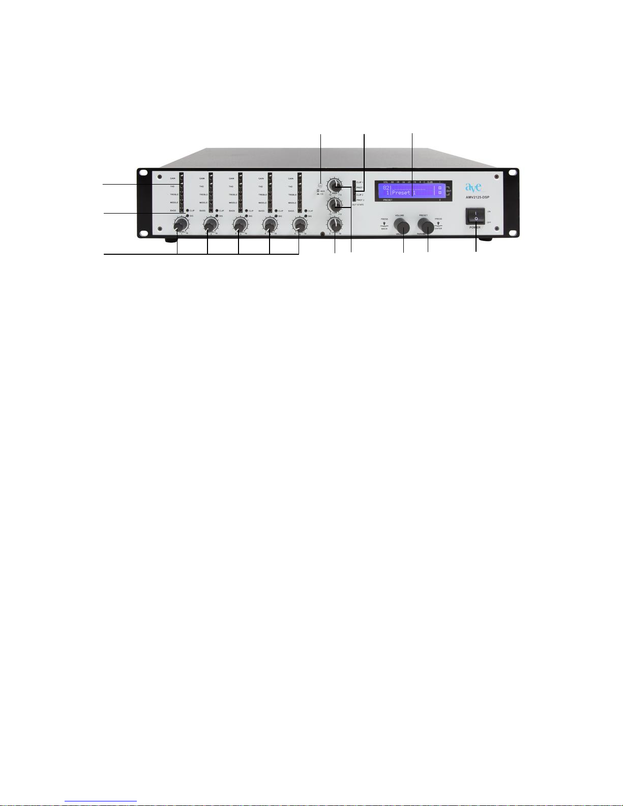
1. Control dial for Gain, THD, Treble, Middle and Bass
The 5 Potentiometer per channel allow following adjustments:
Gain: The Gain-controller customizes the amplification of the channel to the level of the signal
source of the input.
With the barrier controller the activating sensibility can be adjusted when the microphone will
be activated
With the 3-Band-Equalizer (hights, middles, depths) the microphone is adapted to the
speaker to achieve an optimized sound.
Treble: 12 dB at 10 kHz
Mid: 12 dB at 700 Hz
Bass: 12 dB at 70 Hz
THD low noise barrier: a noise gate (barrier), which defines the activating sensibility of the
microphones can be adjusted here. The barrier for the 5 microphone inputs are adjusted by a
potentiometer respectively.
2. Gate- und Clippingdisplay (for channel 1 – 5): Optical display of activated e.g. overdriven
input.
3. Volume control (for channel 1 – 5): with these volume controls all levels of the signal
sources can be adjusted which are plugged to the microphone/line-inputs (26). During
installation by authorized experts the optimized level will be marked with a sign.
4. Volume control for CD/Aux
5. Depth- and Hights- control for CD/Aux
6. Volume/Value“-control dial: control dial with integrated caliper, is used to regulate the
“Master Volume”, i.e. the volume for all outgoing signals.
7. „Preset/Parameter“-control dial: control dial with integrated caliper is used to access the
different presets.
8. power switch: by using the power switch the unit can be switched on and off.
9. LCD-Display: the high luminous display contributes a clear and user-friendly handling.
10. Out State display:
Red: amplifier overdriven at input
Yellow: failure – when switching on the amplifier the LED flashes short time and disappears
afterwards.
11. channel switch CD/Aux: Sound carrier selection. The reproducers can be connected at the
backside.
Page 4

User guide AMV 2125-DSP page 4
12 11
1
2
10
3 4 5 6 7 8 9
1. Mains connection: The unit is supported with power, when the cable is connected to a 230 V
alternating current source.
2. Fuse: 3,15 A
3. Outputs: connections for the activation of the output stages
4. Optional Remote Control for the outputs 1 and 2
5. Mute-switch: for all or alternatively favoured inputs
6. Recording: Cinch-connections for recording units
7. CD-replay: Cinch-connections for music transmission with CD
8. Replay: Cinch-connections for music transmission (Aux)
9. Direct OUT: direct output without signal processing. This output can be used e.g. for
transmission of directly room scenery to external accommodations.
10. Level Direct OUT: controls the sound of direct output
11. Mikrophone/Line-inputs
12. Feeder clip for loudspeaker (50, 70, 100 V, 4 Ohm)
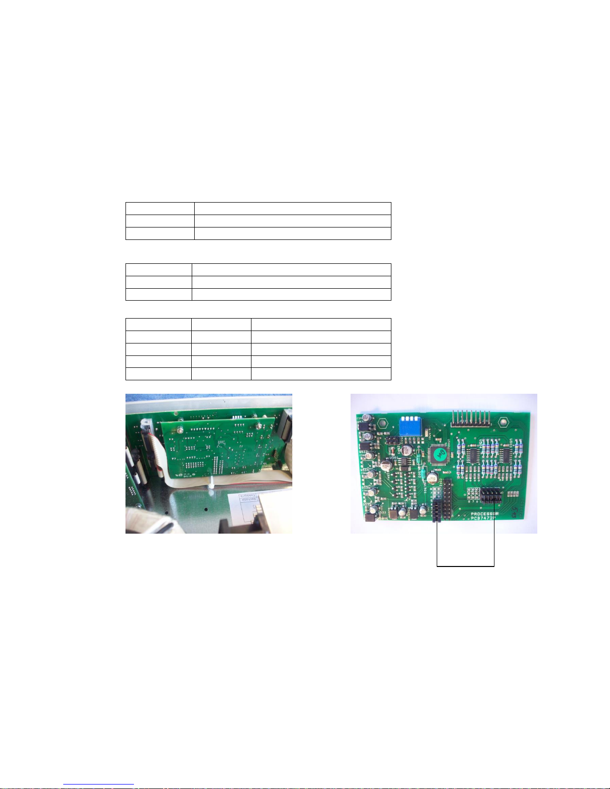
Optional Remote Control outputs 1 and 2
By insertion of both prints the possibility is given to regulate
the outputs from distance. Therefore Jumper 11 and 12 must
be unsoldered.
Mute-Switch for all or alternatively favoured inputs. By
removing of one of Jumper 1 – 6 you can obtain that a
favoured input is active despite of mute-switch.
Page 5
User guide AMV 2125-DSP page 5
3. Handling the unit
3.1 Microprocessor gate control
Continous level monitoring of 5 input channels by RISC microprocessor
Level compare accuracy better than ±2 dB
Channel on attack time less than 10 ms
Channel on hold time 256 ms (default) / 512 ms, selectable via switch
Last On (default) / Channel 1 On, selectable via switch, hysteresis 6 dB
Simultaneous active channels: none, two, three or four.
Switch 1
Hold time
Off
256 ms
On
512 ms
Switch 2
Active channel
Off
Last channel
On
Channel 1
Should the microphones work
independently of the automatic remove
the nut M3. Now you can pull the
board to the rear.
After removal of the corresponding
jumpers tighten the board again.
Switch 3
Switch 4
Active channels
Off
Off
None
Off
On
2 channels
On
Off
3 channels
On
On
4 channels
Page 6

User guide AMV 2125-DSP page 6
3.2 Programmable settings („presets“)
The AMV 2125-DSP combines numerous integrated functions with very simple operation. Even in
acoustically difficult environments, best results are achieved. So-called „presets“ can easily be
programmed. No less than 20 of these preset slots enable programming for any application (e.g:
“Sunday”, “regular church” or as well for different speakers) and make them available to the user at
the touch of one’s fingertips.
For each preset, the following parameters are programmed:
the master volume i.e. the total volume of all outgoing signals
which of the both outputs are to be active
a preset name. This way the different settings are immediately distinguishable.
3.3 Using of different presets
Turn the unit on with the main on/off switch.
The welcome message will appear in the display and the parameter set, starting the program.
After a few seconds, it will disappear and the settings of the current preset will show up.
Below, an example is given.
Here one can see the current preset name (in this case „Sonntag“) as well as the value of the
master volume in percent (total output volume, in this case 80%). The bar above the preset
name is an analogue representation of the master volume.
On the right-hand side of the display the two little squares represent the 2 outputs (the
numbers 1 through 2 are written on the side of the display). A dot within a square indicates
that this particular output is active. In the example both outputs are active.
The preset settings can be guarded against accidental changes. In this „preset-protection
mode“, changes can only be made by pushing and turning the dial at the same time.
In order to switch from one preset to another, push the preset knob while turning it (only
necessary in the “preset-protection-mode”) until the desired preset shows up in the display;
then let go. Now, all is set for the next application.
3.4 Temporarily changing an existing preset
Should it become necessary to change the volume of a given preset, push the volume knob
(only necessary in the “preset protection mode”) while turning it to set the desired value. This
change is only temporary, i.e. once the unit is turned off and back on again, the original preset
is active again.
Page 7

User guide AMV 2125-DSP page 7
4. Extended functions
4.1 Programming a new preset
This section describes how to programm one of the 20 preset slots, for example, give a preset
name and select the desired master volume and outputs.
First, turn the unit off with the main on/off switch in the back.
Then, turn the unit back on, while pushing the preset dial. Keep the dial pushed until the main
menu appears (see below).
The four items „preset“, „parameters“, „config“, and „utility“ appear.
Push the preset knob again and „Edit Preset 1“ appears (see below).
In case you wish to choose a different preset slot, turn the volume knob (1-20). By pushing the
preset knob e.g. following picture appears
A yet unused preset slot can be identified by the fact that it does not yet have given preset
name, (for example “Sonntag”) but merely „preset“ and a number (e. g. „preset 12“).
Push the preset dial. Now you can determine the preset name. The cursor will blink under the
first character.
By turning the volume knob, the following letters, numbers, and special characters will appear
in this order: A-Z, Ä, Ö, Ü, a-z, ä, ö, ü, 0-9, space, ! „ # $ % & ’ ( ) * + , - . /
Pushing the preset dial will confirm the current character und move the cursor one position to
the right. Now you can set the next character.
When you’ve filled in the preset name, turn the preset dial one click to the right to now
determine the master volume for this preset. Set the value by turning the volume dial. The
values range from 0 to 100%. The corresponding value in dB is given in brackets.
Now turn the preset dial again one click to the right in order to determine the outputs for this
preset.
When pushing the preset dial, the 2 outputs will appear one after the other with their
respective names. „On“, as well as a dot in the little square, indicating that this output is active.
By turning the volume dial one click, the shown output can be either activated or deactivated.
Now the programming for this preset is complete. By pushing the volume knob, you will exit
the programming mode. You will be asked whether you would like to „Save changes?“
Pushing the volume button indicates „yes“ and your changes will be saved ( „Saving … do
not interrupt“). Pushing the preset knob indicates „no“ and the display will show „Changes
discarded!“
To change another preset, press briefly the “Volume”-knob. You will enter back to the preset-
menu. Now change to the designated preset and proceed like described above.
Page 8

User guide AMV 2125-DSP page 8
THE FOLLOWING MODIFICATIONS ARE TO BE PERFORMED BY
QUALIFIED AUDIO TECHNICIANS ONLY.
4.2 The Parameter-Menu / Programming of AMV 2125-DSP
Functions and settings in the parameter domain should be changed by qualified personnel
only. The only exception is the programming of a new preset as described in section 4.1.
The digital control boasts the great advantage of the programmability of various functions. In
this parameter menu, not only the presets are programmed, but among others, the equalizers
and the parameters for feedback elimination are set. In fact, the entire programming of the
GENIO 10 is done here with menu-driven user guidance by using the display and merely the
“Volume” and “preset”-knobs. No PC or Laptop is required.
In order to enter the parameter menu first turn the unit off.
Then, turn it back on again while pushing the “Volume” dial until the parameter menu with its
four items “preset, parameters, config, and service” appear.
By turning the preset dial, you can change from one menu item to the next which is indicated
by a small triangle.
By pushing the preset dial, you choose the mode „Edit Parameterset 1“ (see below)
By turning the Volume-dial you can choose which Parameterset you would like to change. You
have 4 possibilities (1-4). Press the “Preset”-knob again and select the equivalent menu.
The following applies:
Turning the preset dial one click to the right will always bring you to the next item of a menu, i.
e. to the next parameter to be programmed. This dial is therefore marked „parameter“. For
simplicity, we will continue to name this dial the preset dial.
Changing a value or character is always done by turning the volume dial. This dial is therefore
also marked „value“. However, here too for simplicity, we will stay with the name of volume
dial.
This dial is a so-called dynamic rotary dial, meaning that when slowly turning it, the value will
change in small increments whereas turning a dial by the same amount more quickly will
change the value proportionally faster. This enables a fast but precise setting of the desired
values.
By pushing the volume dial, you will go up one level in the menu structure. Whenever you
have changed any parameter, you will be asked whether you would like to „Save changes?“
Pushing the volume dial indicates „yes“ and your changes will be saved ( „Saving … do not
interrupt“). Pushing the preset dial indicates „no“ and the display will show „Changes
discarded!“.
The following 4 sections will describe the programming possibilities of the 4 menu items.
4.2.1 Preset
Select the desired number out of Edit-Preset-Menu.
Preset name: Determine the name for a given preset. The procedure is described in detail in
section 4.1.
Preset master volume: Setting the master volume for a given preset.
Page 9

User guide AMV 2125-DSP page 9
Preset output: Choose the desired outputs for a given preset. The procedure is described in
detail in section 4.1.
4.2.2 Parameters
Select the desired number out of Edit-Preset-Menu (see below).
Level: Determine the level for each output. Set the desired value by turning the volume dial.
Pushing the preset dial will bring you to the next output. With this individual level setting, you
will achieve an optimal balance of the outputs which will remain even when changing the
master volume.
Delay: Delay time for both outputs. It can be set in 1-meter increments and the corresponding
delay time is given in milliseconds (calculated according to a speed of sound of 343 m/s,
corresponding to a room temperature of 20 °C). Here, too, pushing the preset dial will move
you from one output to the next.
Graph EQ: Set the level of the 31 bands of the graphic equalizer for each of the 2 outputs
(see picture below).
By turning the preset dial, you will move to the next frequency; again by pushing it, you will
move to the other output to program the overall 62 levels. By turning the “Volume” dial you can
adjust the respective level.
Param EQ 1 Freq: Set the 1st frequency of the full parametric equalizers (range: 20 Hz to
20.45 kHz). Here, too, the value is set with the volume dial. Pushing the preset dial will bring
you to the next output, so you can set the first frequency for each output.
Param EQ 1 Gain: Set the gain of the 1st band (range: +18 to -44 dB). Between +18 and -20
dB very fine 0.5 dB increments are possible.
Param EQ 1 Q: Set the Q-factor for the 1st band (range: 0.2 to 100; logarithmic increments
0.2, 0.22, 0.25, 0.28, 0.32, etc.). The high Q-factors enable extremely narrow-band notchfilters for ideal feedback elimination.
Param EQ 2-6 Freq: Proceed as described above for bands 2 to 6 of the parametric equalizer
Param EQ 2-6 Gain: Proceed as described above for bands 2 to 6 of the parametric equalizer
Param EQ 2-6 Q: Proceed as described above for bands 2 to 6 of the parametric equalizer
Limiter: Can be individually set for each output. By pushing the preset dial, you can chose the
output; turning the volume dial by one click, you can turn the limiter either „on“ or „off“.
By pushing the volume dial you will return back to the parameter menu. In case you have
changed any parameters, you will be asked whether you would like to save them.
Page 10

User guide AMV 2125-DSP page 10
4.2.3 Configuration
With config you have the possibility to decide with which preset and parameterset the program
will start when turned on. Further adjustments will be described below.
By pressing the „Preset“ dial you will enter to the Config-menu, when the little triangle is next
to “Config” (see below)
Now you can see the Startup-Preset starting the program on the display. By turning the
“Volume” dial you can change with which preset the program should start with (1-20).
By turning the “Preset” dial you will enter to the Startup-Parameterset-Menu. Here you can
select with which parameters the program should start with (1-4).
VU Out: By turning the volume dial, you can choose which of the two outputs shall be shown
as VU-meters on the display.
LCD contrast: Set the contrast of the LCD display from 0 to 50 for optimal readability.
Vol/Preset protect: The protection of the settings is such that changes (e. g. changing
between presets or temporary volume changes) can only be performed while pushing and
turning the dials at the same time. This is intended to safeguard the settings from accidental
changes. If this protection is turned off, changes can be made by simply turning the dials
without pushing them. Turning the volume knob by one click either enables or disables the
protection.
Welcome screen Line 1: Set the first line (16 characters) of the welcome text that shows up
when powering up the unit. The cursor will blink under the first character. By turning the
volume dial, the following letters, numbers, and special characters will appear in this order: AZ, Ä, Ö, Ü, a-z, ä, ö, ü, 0-9, space, ! „ # $ % & ’ ( ) * + , - . / Pushing the preset dial will
confirm the current character und move the cursor one position to the right. Now you can set
the next character.
Welcome screen Line 2: Set the second line (16 characters) of the welcome text that shows
up when powering up the unit.
Output 1 Name: Determine the name of the first output. 8 characters are available for this
name (e.g. nave, gallery, etc.)
Output 2 Name: same procedure as in Output Name 1
4.2.4 Utility
Inside this menu you have the possibility to copy a parameterset into another parameterset.
Turn the “Volume” dial until the small triangle is next to “Utility” and press the “Preset” dial.
Now you can see “Copy/Firmware” on the display. By pressing the dial again the following
menu will appear (see below)
By turning of the „Volume“ dial the source- and target parameterset for the copy process can
be determined. When the triangle is on Copy, press the “preset” dial. Now the designated
parameterset is copied.
Page 11

User guide AMV 2125-DSP page 11
Firmware: Displays the current firmware version of the unit.
4.3 Table with all programmable parameters
Where is which parameter set?
The following table lists the parameter menu with its items and parameters
Item
Parameter
Description
Preset
Preset Name
Name of the Preset
Preset Master Volume
Master volume of the preset
Preset Output
Choice of active outputs
Parameters
Level
Level of each output
Delay
Delay times for the outputs
Graph. EQ [31 Frequencies]
Level of 31st Band of graphic equalizer
adjustable for each output
Param. EQ 1 Freq.
Frequency of the 1st parametric
equalizer; adjustable for each output
Param. EQ 1 Gain
Gain of the 1st parametric equalizer,
adjustable for each output
Param . EQ 1 Q
Q-factor of the 1st parametric
equalizer, adjustable for each output
… [same for the other
parametric equalizers]
Limiter on/off
Set limiter individually for each output
Config
Startup Preset 1-20
Selection of preset starting the program
Startup Parameterset 1-4
Selection of parameterset starting the
program
VU Out
output VU
LCD Contrast
Contrast of the LCD display
Vol/Preset Protect
Control dial protection on/off
Welcome screen Line 1
Adjust 1st line of welcome screen
Welcome screen Line 2
Adjust 2nd line of welcome screen
Output 1 Name
Name of 1st output
Output 2 Name
Name of 2nd output
Utility
Copy Parameterset
Copies an accumulated parameterset
to another parameterset
Firmware
Firmware-Version
BEFORE OPENING THE UNIT, TURN IT OFF AND
REMOVE THE POWER CORD.
ONLY THEN REMOVE THE SCREWS AND THE COVER.
Page 12

User guide AMV 2125-DSP page 12
5 Technical Specifications
DSP Structure
2 outputs with completely independent 24 bit / 96 kHz digital audio processing output levels
Output level and master volume
Independent setting of output level for each channel: +12 to - dB (very good resolution with precise 0.5
dB increments from +12 to -20 dB)
Common setting for overall output level (master volume): +10 to - dB (precise 0.5 dB increments from 10 to -20dB)
Delay
For both channels
Delay: 0 to 680 ms (0 to 233 meters).
Settings: in meters (1-meter increments, calibrated to an acoustic velocity of 343 m/s, according to a
room temperature of 20°C)
Graphic equalizer
62 bands (31 per output)
Fully parametric equalizer
12 bands (6 per channel)
Frequency: 20 Hz to 20.45 kHz (each band), very good resolution of 96 steps per octave
Gain: +18 to -44 dB (each band, fine 0.5 dB steps from +18 to -20 dB)
Q-factor: 0.2 to 100 (logarithmic scaling 0.2, 0.22, 0.25, 0.28, 0.32, etc.), this permits extremely
narrowband notch filters for feedback elimination
Limiter
Can be enabled separately for each channel, reliably protects the sound system from sudden,
unexpected increases in signal level of each output
Parameter Sets
4 sets
All DSP Parameter will be programmed
Preset
Available number of presets: 20
Preset parameters: master volume, output on/off, preset name
VU meter
VU meter for one channel (freely selectable
VU meter range: 0 to -50 dB, 14 bars (0 dB corresponds to the peak output level of the DSP output)
Volume bar: renders graphic representation of the master volume
User Interface
Display: 2 lines of 20 characters each, user input via two rotary encoders with integrated pushbuttons
All settings are adjusted directly on the instrument by menu-driven user guidance (i.e. without external
PC or laptop)
Separate parameter domain (EQs, delays, etc.) and user domain (master volume, preset, channel on/off)
The parameter domain is safeguarded against unauthorized access, the safety mechanism works
without a password (eliminates the problem of forgotten passwords)
The user domain can be protected against accidental change of settings
Freely definable welcome message upon power-up (2 lines of 16 characters each)
For each channel a name can be freely defined (up to 7 characters) which appears in all relevant menus
on the display
DSP internals
ADC / DAC resolution and sampling rate: 24 bit, 96 kHz
DSP internal accuracy: 48 bit, entire data path
DSP audio clock frequency: 96 kHz, entire data path (thus, EQs are very precise at high frequencies)
DSP internal overload reserve: 36dB (renders a DSP internal overload in conventional applications
virtually impossible)
Page 13

User guide AMV 2125-DSP page 13
Line electronic symmetric
Frequency response (-3dB): 30 Hz to 19 KHz
Gain: 43 mV (-25 dBu) 1dB
Microphone
Frequency response (-3dB) input microphone: 160 Hz to 19 KHz
Input impedance: 0.6 mV (-62 dBu) / 45 mV (-25 dBu) 1 dB
CMMR: > 60 dB at 1 kHz
THD level: 10 dB
Hi-pass-filter: 160 Hz, 6 dB/oct
Phantom power: + 48 V for each input selectable
3-band equalizer
High-frequency: 12 dB at 10 kHz
Mid-frequency: 12 dB at 700 Hz
Low-frequency: 12 dB at 70 Hz
LED-Display: green (Signal), red (clipping)
AUX/CD
Impedance AUX: 15 k
Impedance CD: 56 k
Input sensitivity AUX: 0 dBu
Input sensitivity CD: +3 dB
Frequency response (-3db), input CD/AUX: 20 Hz to 20 KHz
Outputs
Output impedance OUT 1, 2: 140 balanced; 70 unbalanced
Output level Out 1, 2: +6 dBu (with master volume at 82 %)
Output level OUT 1, 2: +9 dBu (with master volume at 100 %)
Output impedance Direct-OUT: 140 balanced; 70 unbalanced
Output level Direct-OUT: +9 dBu (variable potentiometer)
Output impedance REC: 70 unbalanced
Output level REC: 0 dBu
Frequency response
-3 dB for CD: 50 Hz – 20 kHz
-3 dB for microphone: 100 Hz – 16 kHz
Noise
Noise level Direct-OUT, loaded, 20 Hz – 20 kHz, potentiometer at 0: -97 dBu
Noise level OUT 1, loaded, 20 Hz – 20 KHz, master volume at 0: -92 dBu
Noise level OUT 1, loaded, 20 Hz – 20 kHz, master volume at 82: -88 dBu
Noise level CD/AUX, loaded, 20Hz – 20 KHz, master volume at 82:-84 dBu
Output power
Output power 1x150W/2x150W/1x240W/2x240W
Output impedance 4 Ohm / 50 V/70V/100V
LED-display yellow (dysfunction), red (overload)
General
Optional remote control for both outputs
Muting for each input
Operating voltage: 230 V~, 50-60 Hz
Power consumption: 80 W/115W/130W/215W
Overall dimensions: (width x height x depth) = 484 x 88 x 350 mm (+60 mm plug); 2 U, 19“
Net weight: approx. 11 kg
Page 14

User guide AMV 2125-DSP page 14
Notice
ALL AVE mbH DESIGN SPECIFICATIONS, FILES, DRAWINGS, TABLES, LISTS,
AND OTHER DOCUMENTS ARE BEING PROVIDED “AS IS.”
AVE mbH MAKES NO WARRANTIES, EXPRESSED, IMPLIED, STATUTORY, OR
OTHERWISE WITH RESPECT TO THE MATERIALS, AND EXPRESSLY
DISCLAIMS ALL IMPLIED WARRANTIES OF NONINFRINGEMENT,
MERCHANTABILITY, AND FITNESS FOR A PARTICULAR PURPOSE.
Information furnished is believed to be accurate and reliable. However, AVE mbH
assumes no responsibility for the consequences of use of such information or for any
infringement of patents or other rights of third parties that may result from its use. No
license is granted by implication or otherwise under any patent or patent rights of
AVE mbH. Specifications mentioned in this publication are subject to change without
notice. This publication supersedes and replaces all information previously supplied.
AVE mbH products are not authorized for use as critical components in life support
devices or systems without express written approval of AVE mbH Corporation.
Trademarks
AVE mbH and the AVE logo are trademarks or registered trademarks of AVE mbH in
the Germany and other countries. Other company and product names may be
trademarks of the respective companies with which they are associated.
Copyright
© 2015 AVE mbH. All rights reserved.
Consulting • Planning • Developing • Assembly of electroacoustic sound systems
AVE GmbH • Gustav-Rau-Straße 6 • 74321 Bietigheim-Bissingen • Germany
Phone +49 (0)7142 78879-0 • Fax +49 (0)7142 78879-18
info@ave-stuttgart.de • www.ave-stuttgart.de
 Loading...