

USER MANUAL
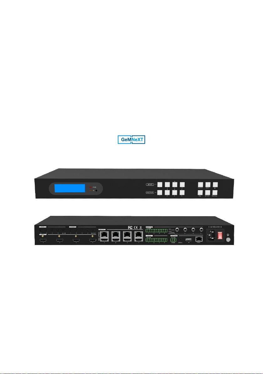
Matrix-4X4-HBT-H2-KIT
4x4 HDMI 2.0 Matrix Kit
All Rights Reserved
Version: Matrix-4X4-HBT-H2-KIT_2018V1.4

4x4 HDMI 2.0 Matrix Kit
Preface
Read this user manual carefully before using the product. Pictures shown in this
manual are for reference only. Different models and specifications are subject to real
product.
This manual is only for operation instruction, please contact the local distributor for
maintenance assistance. The functions described in this version were updated till
August, 2018. In the constant effort to improve the product, we reserve the right to
make functions or parameters changes without notice or obligation. Please refer to the
dealers for the latest details.
FCC Statement
This equipment generates, uses and can radiate radio frequency energy and, if not
installed and used in accordance with the instructions, may cause harmful interference
to radio communications. It has been tested and found to comply with the limits for a
Class B digital device, pursuant to part 15 of the FCC Rules. These limits are designed
to provide reasonable protection against harmful interference in a commercial
installation.
Operation of this equipment in a residential area is likely to cause interference, in
which case the user at their own expense will be required to take whatever measures
may be necessary to correct the interference.
Any changes or modifications not expressly approved by the manufacture would void
the user’s authority to operate the equipment.

4x4 HDMI 2.0 Matrix Kit
SAFETY PRECAUTIONS
To ensure the best performance from the product, please read all instructions carefully
before using the device. Save this manual for further reference.
⚫ Unpack the equipment carefully and save the original box and packing material for
possible future shipment.
⚫ Follow basic safety precautions to reduce the risk of fire, electrical shock and injury
to persons.
⚫ Do not dismantle the housing or modify the module. It may result in electrical shock
or burn.
⚫ Using supplies or parts not meeting the specifications of product may cause damage,
deterioration or malfunction.
⚫ Refer all servicing to qualified service personnel.
⚫ To prevent fire or shock hazard, do not expose the unit to rain, moisture or install this
product near water.
⚫ Do not put any heavy items on the extension cable in case of extrusion.
⚫ Do not remove the housing of the device as opening or removing housing may
expose you to dangerous voltage or other hazards.
⚫ Install the device in a place with fine ventilation to avoid damage caused by
overheat.
⚫ Keep the module away from liquids.
⚫ Spillage into the housing may result in fire, electrical shock, or equipment damage. If
an object or liquid falls or spills on to the housing, unplug the module immediately.
⚫ Do not twist or pull by force ends of the optical cable. It can cause malfunction.
⚫ Do not use liquid or aerosol cleaners to clean this unit. Always unplug the power to
the device before cleaning.
⚫ Unplug the power cord when left unused for a long period of time.
⚫ Information on disposal for scrapped devices: do not burn or mix with general
household waste, and please treat them as normal electrical wastes.

4x4 HDMI 2.0 Matrix Kit
Table of Content
1. Product Introduction .................................................................................................... 1
1.1 Features ............................................................................................................ 1
1.2 Package List ...................................................................................................... 2
2. Specification ............................................................................................................... 3
2.1 HDBaseT 4x4 HDMI 2.0 Matrix.......................................................................... 3
2.2 HDBaseT Receiver ............................................................................................ 4
3. Panel Description ........................................................................................................ 5
3.1 Matrix Front Panel ............................................................................................. 5
3.2 Matrix Rear Panel .............................................................................................. 6
3.3 Receiver Front Panel ......................................................................................... 7
3.4 Receiver Rear Panel .......................................................................................... 8
4. System Connection ..................................................................................................... 9
4.1 Usage Precaution .............................................................................................. 9
4.2 System Diagram ................................................................................................ 9
5. Button Control ........................................................................................................... 10
5.1 Signal Switching .............................................................................................. 10
5.2 EDID Management .......................................................................................... 11
5.3 Inquiry Mode .................................................................................................... 13
5.4 Recall Preset ................................................................................................... 14
6. IR Control .................................................................................................................. 15
6.1 IR Remote Control ........................................................................................... 15
6.2 IR Pass-through Control .................................................................................. 16
6.2.1 Control Local Input Device from Local ................................................... 16
6.2.2 Control Local Input Device from Remote ............................................... 18
6.2.3 Control Remote Output Device from Local ............................................ 20
7. GUI Control ............................................................................................................... 22
7.1 Video Switching ............................................................................................... 23
7.2 Coaxial Audio Control ...................................................................................... 24
7.3 Configuration ................................................................................................... 25

4x4 HDMI 2.0 Matrix Kit
7.4 CEC Control .................................................................................................... 28
7.5 RS232 Control ................................................................................................. 30
7.6 Access Setting ................................................................................................ . 31
7.7 Interface Setting............................................................................................... 32
7.8 Network Setting ............................................................................................... 33
7.9 GUI Upgrade ................................................................................................... 34
8. RS232 Control .......................................................................................................... 35
8.1 RS232 Control Connection .............................................................................. 35
8.1.1 Control the Matrix from Local................................................................. 35
8.1.2 Control the Matrix from Remote ............................................................. 36
8.1.3 Control the Remote Third-party Device from Local ................................ 37
8.1.4 Control the Local Third-party Device from Remote ................................ 38
8.2 RS232 Control Software .................................................................................. 39
8.3 RS232 Commands for Controlling Matrix ........................................................ 40
8.3.1 System Command ................................................................................. 40
8.3.2 Signal Switching .................................................................................... 41
8.3.3 Preset Management .............................................................................. 42
8.3.4 Output Audio Control ............................................................................. 43
8.3.5 EDID Configuration ................................................................................ 43
8.3.6 HDCP Compliance ................................................................................ 45
8.3.7 Baud Rate Setting ................................................................................. 45
8.3.8 CEC Control .......................................................................................... 46
9. Panel Drawing .......................................................................................................... 48
9.1 HDBaseT 4x4 HDMI 2.0 Matrix........................................................................ 48
9.2 HDBaseT Receiver .......................................................................................... 48
10. Troubleshooting & Maintenance ............................................................................. 49
11. Customer Service ................................................................................................... 50

4x4 HDMI 2.0 Matrix Kit
1
1. Product Introduction
Thanks for choosing the professional 4x4 Matrix with four Receivers! The matrix is a
four-input by four-output HDBaseT and HDMI matrix with HDCP 2.2 and up to
4K/UHD@60Hz video support. It transmits 4K video to distances up to 131 feet (40
meters) and 1080p video to distances up to 229 feet (70 meters) over a single CATx
Ethernet cable. HDBaseT outputs support the Power over Cable (PoC) feature,
allowing the receivers to draw their power from the matrix over the HDBaseT cable.
The matrix features comprehensive EDID management and advanced HDCP handing
to ensure maximum functionality with a wide range of video sources.
The matrix not only supports bi-directional IR, RS232 extension but also has IR,
RS232, and TCP/IP control options.
The product provides performance in control and transmission, which could be used in
a number of different installation scenarios, for example, with computers, for
monitoring purposes, large screen displays, conference systems, television education,
bank security institutions, etc.
1.1 Features
⚫ Supports HDMI resolution up to 4K@60Hz 4:4:4.
⚫ Fully compliant with the HDMI 2.0 and HDCP 2.2.
⚫ Transmits 4K signal to the distance up to 131 feet (40 meters) and 1080p signal to
the distance up to 229 feet (70 meters) over a single CATx Ethernet cable.
⚫ Supports 12V PoC, allowing the receivers to draw their power from the
matrix/transmitter over the HDBaseT cable.
⚫ Features four HDBaseT outputs and includes HDMI local outputs with
corresponding digital and analog audio outputs.
⚫ Features four digital coaxial audio outputs which can be controlled via GUI or
RS232 commands to separate the embedded audio from HDMI inputs and
HDBaseT outputs.
⚫ Supports comprehensive EDID management and advanced HDCP handling.
⚫ Controllable via front panel, RS232, IR and TCP/IP (use the built-in GUI).

4x4 HDMI 2.0 Matrix Kit
2
1.2 Package List
HDBaseT 4x4
HDMI 2.0 Matrix
⚫ 1x HDBaseT 4x4 HDMI 2.0 Matrix
⚫ 2x Mounting Ears with 6 Screws
⚫ 4x Plastic Cushions with 4 Screws
⚫ 1x IR Receiver
⚫ 1x IR Remote
⚫ 1x 3-pin to DB9 RS232 Cable
⚫ 9x 3-pin RS232 Terminal Blocks
⚫ 1x Power Cord
HDBaseT Receiver
⚫ 4x HDBaseT Receivers
⚫ 8x Mounting Ears with 8 Screws
⚫ 16x Plastic Cushions
⚫ 4x 3-pin RS232 Terminal Blocks
⚫ 1x User Manual
Note: Please contact your distributor immediately if any damage or defect in the
components is found.

4x4 HDMI 2.0 Matrix Kit
3
2. Specification
2.1 HDBaseT 4x4 HDMI 2.0 Matrix
Video Input
Input
(4) HDMI
Input Connector
(4) Type-A female HDMI
Input Video Signal
HDMI
HDMI Input Resolution
Up to 4Kx2K@60Hz 4:4:4
Video Output
Output
(4) HDBaseT, (4) HDMI
Output Connector
(4) RJ45, (1) Type-A female HDMI
Output Video Signal
HDMI, HDBaseT
HDMI Output Resolution
Up to 4Kx2K@60Hz 4:4:4
HDBT Output Resolution
Up to 4Kx2K@60Hz 4:2:0
Audio Output
Output
(4) Stereo analog audio, (4) Digital coaxial audio
Output Connector
(4) 3-pin terminal blocks, (4) Coaxial jacks
Output Analog Audio Format
PCM
Output Digital Audio Format
PCM
Audio Output Impedance
70Ohms
Frequency Response
20 Hz to 20 kHz, ±3dB
Common Mode Rejection
Ratio (CMRR)
>70dB at 20Hz to 20KHz
Signal to Noise Ratio (SNR)
100dB (Max)
Control
Control port
(4) IR IN, (1) IR ALL IN, (4) IR OUT, (1) IR ALL OUT,
(1) IR EYE, (5) RS232, (1) FIRWARE, (1) TCP/IP
Control Connector
(11) 3.5mm mini jacks, (5) 3-pin terminal blocks,
(1) Micro USB, (1) RJ45
General
Transmission Mode
HDBaseT
Transmission Distance
1080p ≤ 229 feet (70 meters),
4K@60Hz ≤ 131 feet (40 meters)
Bandwidth
18Gbps
Operation Temperature
-10 ~ +55℃
Storage Temperature
-25 ~ +70℃
Relative Humidity
10% ~ 90%

4x4 HDMI 2.0 Matrix Kit
4
External Power Supply
100V~240V AC, 50/60Hz
Power Consumption
85W (Max)
Dimension (W*H*D)
436.4mm x 44mm x 340mm
Net Weight
3.2kg
2.2 HDBaseT Receiver
Input
Input Signal
(1) HDBT IN
Input Connector
(1) RJ-45
Output
Output
(1) HDMI
Output Connector
(1) Type-A female HDMI
Control
Control Port
(1) IR IN; (1) IR OUT; (1) RS232
Control Connector
(2) 3.5mm mini jacks; (1) 3-pin terminal block
General
Resolution Range
Up to 4K×2K@60Hz 4:4:4
Bandwidth
18Gbps
Transmission Mode
HDBaseT
Transmission Distance
1080p ≤ 229 feet (70 meters),
4K@60Hz ≤ 131 feet (40 meters)
HDMI Standard
HDMI 2.0 & HDCP 2.2
Operation Temperature
-10 ~ +55℃
Storage Temperature
-25 ~ +70℃
Relative Humidity
10% ~ 90%
External Power Supply
Input: 100VAC~240VAC, 50/60Hz, Output: 12V DC 2A
Power Consumption
14W (Max)
Dimension (W*H*D)
115mm x 16 mm x 84mm
Net Weight
153g

4x4 HDMI 2.0 Matrix Kit
5
3. Panel Description
3.1 Matrix Front Panel
① LCD Screen: Presents real-time operation status.
② Power LED: Illuminates GREEN when the device is in standby mode, illuminates
RED when device is powered on.
③ IR sensor and its LED: Illuminates RED when the IR sensor receivers an IR signal
from the include IR remote to control the matrix. The IR sensor is on the right side
of the LED.
④ INPUT: Four buttons for input source selection. Button 3 also serves as UP
navigation button.
⑤ OUTPUT: Four buttons for output channel selection. Button 2, 3 and 4 also serve
as LEFT, DOWN and RIGHT navigation buttons.
⑥ Menu buttons:
⚫ CLEAR: Cancel the current commands if ENTER has not been pressed.
⚫ EDID: Enable input port to manually capture and learn the EDID data of output
devices.
⚫ LOCK: Lock and unlock the front panel buttons.
⚫ ALL: Select all inputs or all outputs together. Please refer to 5 Button Control
for more details.
⚫ ENTER: Confirm the current command or press and hold for 3 seconds to enter
inquiry mode.
⚫ RECALL: Invoke a previous saved preset layout.
ALL ENTER RECALL
CLEAR EDID
1 2 3 4
1 2
3 4
INPUT
PWR
IR
1
3 5 6
4
2

4x4 HDMI 2.0 Matrix Kit
6
3.2 Matrix Rear Panel
① INPUT: Four Type A female HDMI input ports to connect HDMI sources.
② IR IN:
⚫ 1~4: Four 3.5mm jacks to connect four IR receivers. Each IR input is associated
with the respective HDBaseT output and cannot be switched separately. It
makes up a bi-directional IR transmission with the IR OUT on the corresponding
HDBaseT receiver.
⚫ ALL IN: 3.5mm jack to connect the IR receiver to transmit the IR signal from the
ALL IN port to all HDBaseT receivers.
③ IR OUT:
⚫ 1~4: Four 3.5mm jacks to connect four IR emitters to send the IR signal
received from the corresponding HDBaseT receivers.
⚫ ALL OUT: 3.5mm jack to connect the IR emitter to send the IR signal received
from all HDBaseT receivers.
④ OUTPUT: Four HDBaseT RJ45 outputs to connect the four HDBaseT receivers,
four local HDMI ports to connect local displays.
⑤ AUDIO OUT:
⚫ Four 3-pin terminal blocks for analog audio output.
⚫ Four coaxial jacks to separate the digital audio from HDMI inputs and HDBaseT
outputs via GUI or RS232 commands.
⑥ RS232: Four 3-pin terminal blocks to control the third-party devices base on
RS232 pass-through feature. There is a one-to-one correspondence between the
four RS232 ports and the four RS232 ports of four HDBaseT receivers.
⑦ CONTROL
⚫ 3-pin terminal block to connect a computer to control the matrix by sending
RS232 commands.
⚫ IR EYE: 3.5mm jack to connect IR receiver to receive IR signal from the
included IR remote to control the matrix.
4
1 234
L R
1
2
3
4
HDBase T HDMI
1 2
3
4
Tx Rx
1 234 ALL IN 1 234
ALL OUT
IR EYERS232
Tx Rx
TCP/IP
Input
De-embedde d
Output
De-embedde d
FW1 2
3
1 234
1
6
7
8
9
2
3
4
5

4x4 HDMI 2.0 Matrix Kit
7
⚫ TCP/IP: Ethernet port to connect with a computer to control the matrix via GUI.
⚫ FW: Micro USB port for firmware upgrade.
⑧ AC100V~240V: Power port to connect an AC 100V~240V power by the power
cord.
⑨ GROUND: Connect to earth to ensure the unit is well grounded.
3.3 Receiver Front Panel
① Switch to select the RS232 control mode:
⚫ CTRL: RS232 pass-through control.
⚫ UPDATE A: Connect the RS232 port to the PC, and then double-click the file
(.bat) to update the Valens IC.
⚫ UPDATE B: Use the same method as for UPDATE A to update the compression
IC.
② POWER LED: Illuminates RED when the device is powered on.
CTRL
UPDATE B UPDATE A
1
2

4x4 HDMI 2.0 Matrix Kit
8
3.4 Receiver Rear Panel
① HDMI OUT: Type A female HDMI output port to connect display.
② RS232: 3-pin terminal block for working with the RS232 port of matrix to control
the third-party device. If one is connected with control device (e.g. PC), and
another one should be connected with the third-party device.
③ IR IN: 3.5mm jack to connect IR receiver.
④ IR OUT: 3.5mm jack to connect IR emitter.
⑤ HDBT IN: HDBaseT RJ45 input to connect the matrix.
⑥ DC 12V power port: DC barrel connector for the AC power adapter. The receiver
can work without power adaptor when the matrix is power on.
1
2
3
4
5
6
DC 12V
Tx Rx
H
D
M
I
O
U
T
HDBT IN
I
R
O
U
T
I
R
IN

4x4 HDMI 2.0 Matrix Kit
9
4. System Connection
4.1 Usage Precaution
⚫ Make sure all components and accessories included before installation.
⚫ System should be installed in a clean environment with proper temperature and
humidity.
⚫ All of the power switches, plugs, sockets, and power cords should be insulated
and safe.
⚫ All devices should be connected before power on.
4.2 System Diagram
Recei ver
Proje ctor
Remot e IR R eceiv er
IR Emit ter
4
1 234
L R
1
2
3
4
HDBaseT HDMI
1 2 3 4
Tx Rx
1 2 3 4
1 234 AL L IN 1 234
ALL OUT
IR EYERS232
Tx Rx
TCP/IP
Input
De-embedded
Output
De-embedded
FW1 2 3
Game C onsol e
IR Emit ter
IR Rece iver
Remot e
Apply T V
Lapto p
4K Blu- Ray
Displ ay
Lapto p Route r
Remot e
IR Re ceive r
HDMI:
IR:
RS232 :
HDBas eT:
Ether net:
Audio :
Ampli fier Speak er
Speak er Speak er S peake r Sp eaker

4x4 HDMI 2.0 Matrix Kit
10
5. Button Control
The matrix can be controlled by using the buttons on the front panel. Whenever a
command is accepted, the indicators of all the buttons pressed will blink three times
then they will go off. If the command fails, the indicators will go off immediately without
blinking.
5.1 Signal Switching
⚫ Switch an input to an output
Operation: INPUT# + OUTPUT# + ENTER
Example: Switch Input 1 to Output 2:
INPUT: OUTPUT:
Note: In default status, 4 IR OUT ports correspond with 4 HDMI INPUTS. When you
switch an HDMI input, the corresponding IR OUT will be switched synchronously.
⚫ Switch an input to several outputs
Operation: INPUT# + OUTPUT# + OUTPUT# +… + ENTER
Example: Switch Input 1 to Output 2, 3, and 4.
INPUT: OUTPUT:
⚫ Switch an input to all outputs
Operation: INPUT# +ALL + ENTER
Example: Switch Input 1 to all outputs.
INPUT:
4x4 HDMI 2.0 Matrix Kit
11
5.2 EDID Management
Please note that the HDBT output will always take priority over the HDMI output when
using the EDID setting commands. Disconnect the cable from the HDBT output if you
need to read the EDID from the HDMI output.
⚫ EDID data transfer
To copy the EDID data from a single output port to only one input port:
Operation: EDID + INPUT# + OUTPUT# + ENTER.
Example: Input 2 reads EDID data from output 4.
INPUT: OUTPUT:
To copy the EDID data from a single output port to all input ports:
Operation: EDID + ALL + OUTPUT# + ENTER
Example: All input ports read EDID data from output 4.
OUTPUT:
⚫ Predefined EDID settings
There are seven types of embedded EDID data as shown below. Select one type of
EDID data as the new EDID setting.
ID
Video Resolution
Audio Format
1
720p 2D
PCM/DTS/Dolby
2
720p 3D
PCM/DTS/Dolby
3
1080p 2D (Default)
PCM
4
1080p 3D
PCM/DTS/Dolby
5
4K@30Hz
PCM/DTS/Dolby
6
4K@60Hz 4:2:0
PCM/DTS/Dolby
7
4K@60Hz 4:4:4
PCM/DTS/Dolby

4x4 HDMI 2.0 Matrix Kit
12
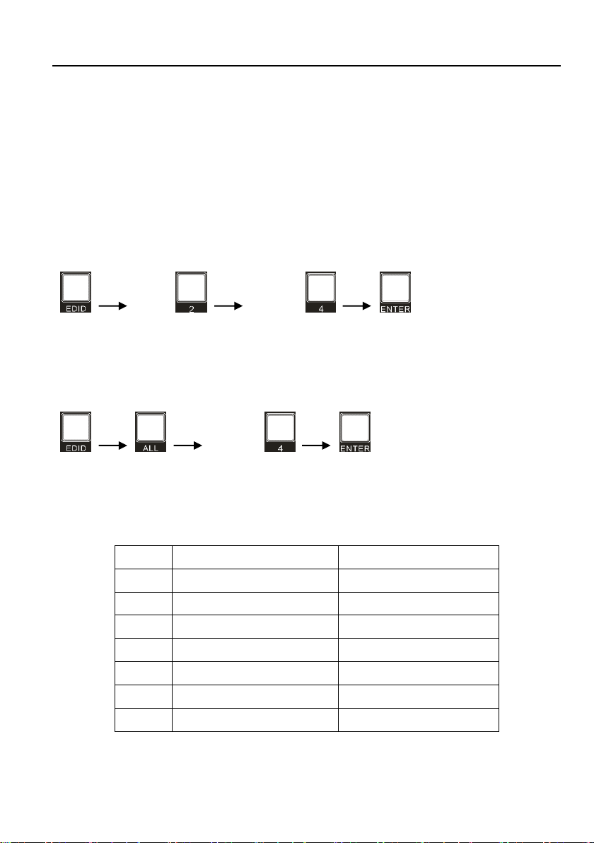
Set a predefined EDID setting for one input port:
Operation:
Step1: Press and hold EDID for 3 seconds to enter the EDID setting mode.
Step2: Select one input.
Step3: Press LEFT and RIGHT navigation buttons to select the predefined EDID data
type.
Step4: Press ENTER to confirm.
Example: Set the EDID data of INPUT 4 to the fourth predefined EDID data type –
1080p 3D:
(Hold for 3 seconds) INPUT:
Set a predefined EDID setting for all input port:
Operation:
Step1: Press and hold EDID for 3 seconds to enter the EDID setting mode.
Step2: Press ALL to select all inputs.
Step3: Select the predefined EDID data type via LEFT and RIGHT navigation buttons.
Step4: Press ENTER to confirm.
Example: Set the EDID data of all input ports to the second predefined EDID data type
– 720p 3D:
(Hold for 3 seconds)

4x4 HDMI 2.0 Matrix Kit
13
5.3 Inquiry Mode
⚫ Check connection status:
Press and hold the ENTER button for 3 seconds to activate the system inquiry menu
on the front panel LCD. Use LEFT and RIGHT navigation buttons to check the
previous or next item respectively.
LCD Screen
Description
Report the connection status of all input ports.
Y means the corresponding input port is connected to a
source device, N means there is no connection between
the input port and source device.
Report the connection status of all output ports.
Y means the corresponding output port is connected to
an output device, N means there is no connection
between the output port and display device.
Report the signal switching status.
Report the HDCP compliance of all input ports.
Y means the input AV signal is transferred with HDCP, N
means the input AV signal content doesn’t contain
HDCP.
Report the HDCP compliance of all output ports.
Y means the output AV signal is transferred with HDCP,
N means the output AV signal content doesn’t contain
HDCP.
⚫ Output Check:
Press any output button to check its corresponding input status. For example, to check
which input is connected to output 2, press Output 2 button, then the LCD screen
displays:
Also, the indicators of the Input 1 and Output 2 buttons will light up for 3 seconds to
show that Input 1 is connected to Output 2.
IN
LINK
1 2 3 4
Y Y N N
OUT
LINK
1 2 3 4
Y Y Y Y
OUT
IN
01 02 03 04
05 05 05 05
IN
HDCP
1 2 3 4
Y Y N N
OUT
HDCP
1 2 3 4
Y Y N N
AV
IR
01-> 02
01-> 02

4x4 HDMI 2.0 Matrix Kit
14
5.4 Recall Preset
Press RECALL button can load layout preset which is saved via RS232 commands
and GUI.
Operation:
Step1: Press RECALL button, the LCD screen displays: PRESET LOAD
Step2: Press LEFT and RIGHT navigation buttons to select PRESET 1~9.
Step3: Press ENTER to confirm.
Example: Recall the Preset 1:
Step1: Press RECALL button.
Step2: Press LEFT and RIGHT navigation buttons to select PRESET 1.
Step3: Press ENTER to confirm.
PRESET LOAD:
PRESET LOAD:
PRESET 1
4x4 HDMI 2.0 Matrix Kit
15
6. IR Control
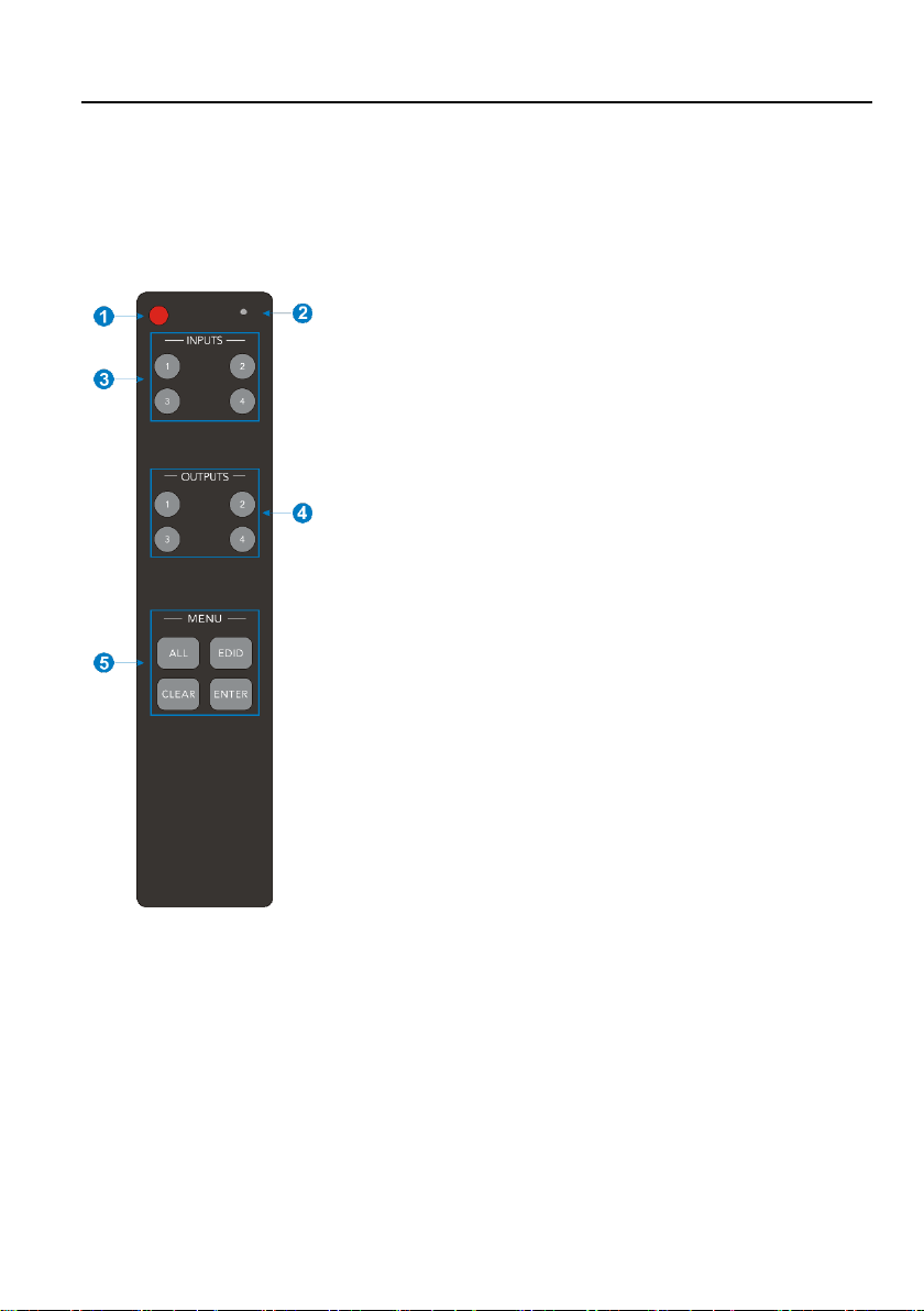
6.1 IR Remote Control
Connect an IR receiver to the IR EYE port, the matrix can be controlled by using the
following IR remote.
① Enter/exit standby mode.
② Blinking red when a button is pressed.
③ Video source selection buttons.
④ Output channel selection buttons.
⑤ Menu buttons:
⚫ ALL: Select all inputs and outputs.
⚫ EDID: Enable input port to manually capture and
learn the EDID data of outputs devices.
⚫ CLEAR: Cancel the current commands, if ENTER
has not been pressed.
⚫ ENTER: Confirm the desired command or press and
hold for 3 seconds to enter into the inquiry mode.
Note: The buttons on the remote control directly
correspond to the buttons on the front panel and perform
the same functions.
4x4 HDMI 2.0 Matrix Kit
16
6.2 IR Pass-through Control
The matrix supports bi-directional IR pass-through, allowing the devices can be
controlled by both source and destination ends. This section provides connection and
switching examples to illustrate possible configurations.
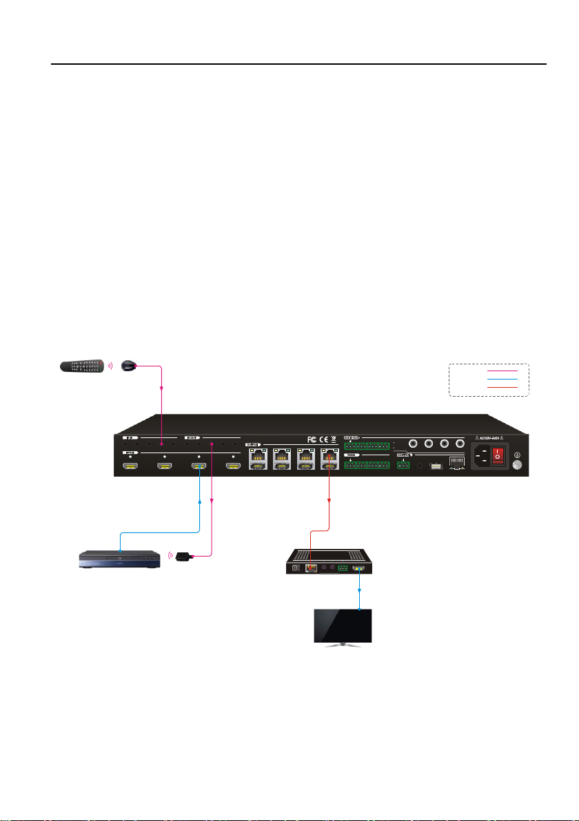
6.2.1 Control Local Input Device from Local
By default, there is a one-to-one correspondence between the IR OUT port on the
matrix and the HDMI input. When switch an HDMI input, the corresponding IR OUT will
be switched synchronously.
Example: Switch HDMI input 3 to HDBaseT output 4.
Connect an IR receiver to the IR IN 4 port, and an IR Emitter to the IR OUT 3 port, the
connection diagram shown as below:
4K Blu -Ray
4
1 234
L R
1
2
3
4
HDBaseT HDMI
1 2
3
4
Tx Rx
1 234
1 234 ALL IN 1 234
ALL OUT
IR EYE
RS232
Tx Rx
TCP/IP
Input
De-embedde d
Output
De-embedde d
FW1 2
3
IR Emi tter
IR Rec eiverRemo te
Rece iver
Disp lay
HDMI :
IR:
HDBa seT:
4x4 HDMI 2.0 Matrix Kit
17
Example: Switch HDMI input 3 to HDBaseT output 2, 3, 4.
Connect three IR Receivers to IR IN 2, IR IN 3 and IR IN 4 port, and an IR Emitter to
the IR OUT 3 port, the connection diagram shown as below:
4K Blu -Ray
4
1 234
L R
1
2
3
4
HDBaseT H DMI
1 2
3
4
Tx Rx
1 234
1 234 ALL IN 1 234
ALL OUT
IR EYE
RS232
Tx Rx
TCP/IP
Input
De-embedded
Output
De-embedded
FW1 2
3
IR Emi tter
IR Rec eiver
Remo te
Rece iver
Disp lay
Rece iver
Disp lay
Rece iver
Disp lay
HDMI :
IR:
HDBa seT:
4x4 HDMI 2.0 Matrix Kit
18
6.2.2 Control Local Input Device from Remote
The same basic principle applies when controlling the local input device from the
remote location.
⚫ Control local input device through IR OUT port
Example: Switch HDMI input 3 to HDBaseT output 4.
Connect an IR Receiver to IR IN port on the receiver, then connect an IR emitter to the
IR OUT 3 on the matrix. The third input source can be controlled through its
corresponding IR output port. The connection diagram shown as below:
4K Bl u-Ray
4
1 234
L R
1
2
3
4
HDBase T HDMI
1 2
3
4
Tx Rx
1 234
1 234 ALL IN 1 234
ALL OUT
IR EYE
RS232
Tx Rx
TCP/IP
Input
De-embedde d
Output
De-embedde d
FW1 2
3
Rec eiver
Disp lay
Rem ote IR Re ceive r
IR Em itter
HDM I:
IR:
HDBa seT:
4x4 HDMI 2.0 Matrix Kit
19
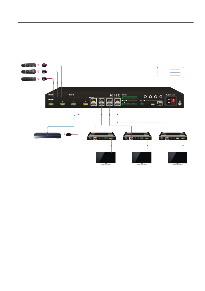
⚫ Control local input device through IR ALL OUT port
The emitter can be connected to the IR ALL OUT port on matrix to control all local
input devices. In this case, the IR receiver must be connected to the IR IN port on each
connected HDBaseT receiver, as shown in the diagram below:
4K Blu -Ray
4
1 234
L R
1
2
3
4
HDBaseT HD MI
1 2
3
4
Tx Rx
1 234
1 234 ALL IN 1 234
ALL OUT
IR EYE
RS232
Tx Rx
TCP/IP
Input
De-embedded
Output
De-embedded
FW1 2
3
Rece iver
Disp lay
Remo te
IR Recei ver
Rece iver
Disp lay
Remo te
IR Recei ver
Rece iver
Disp lay
Remo te
IR Recei ver
IR Emi tter
HDMI :
IR:
HDBa seT:
4x4 HDMI 2.0 Matrix Kit
20
6.2.3 Control Remote Output Device from Local
The remote displays can be controlled from the local matrix location.
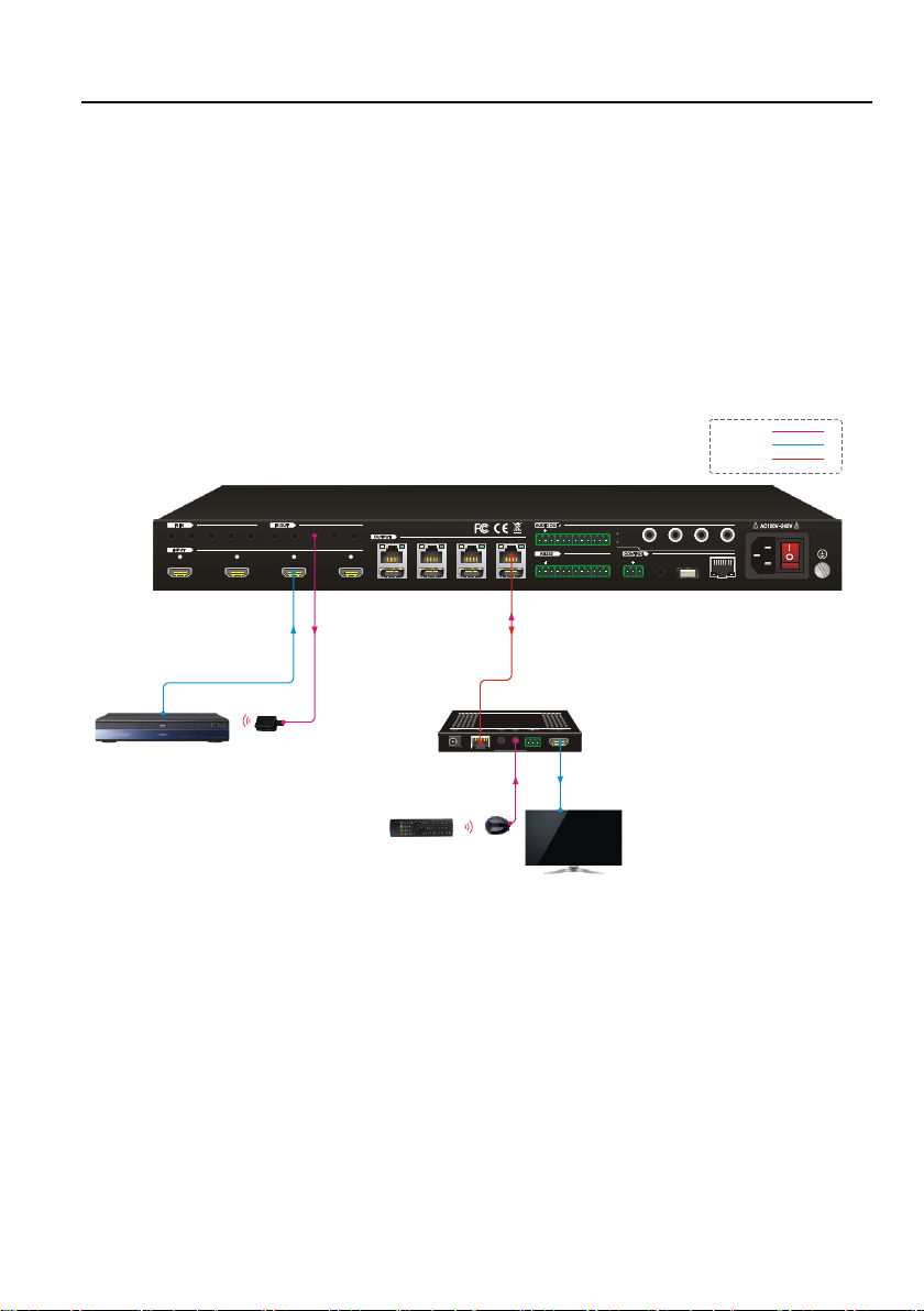
⚫ Control remote device through IR IN port
Example: Switch HDMI input 3 to HDBaseT output 3.
Connect an IR Receiver to IR IN 3 port on the matrix, then connect an IR emitter to the
IR OUT on the receiver, as shown in the diagram below:
4K Blu -Ray
4
1 234
L R
1
2
3
4
HDBaseT HDMI
1 2
3
4
Tx Rx
1 234
1 234 A LL IN 1 234
ALL OUT
IR EYE
RS232
Tx Rx
TCP/IP
Input
De-embedded
Output
De-embedded
FW1 2
3
IR Rec eiver
Disp lay Remo te
Rece iver
Disp lay
IR Emi tter
HDMI :
IR:
HDBa seT:

4x4 HDMI 2.0 Matrix Kit
21
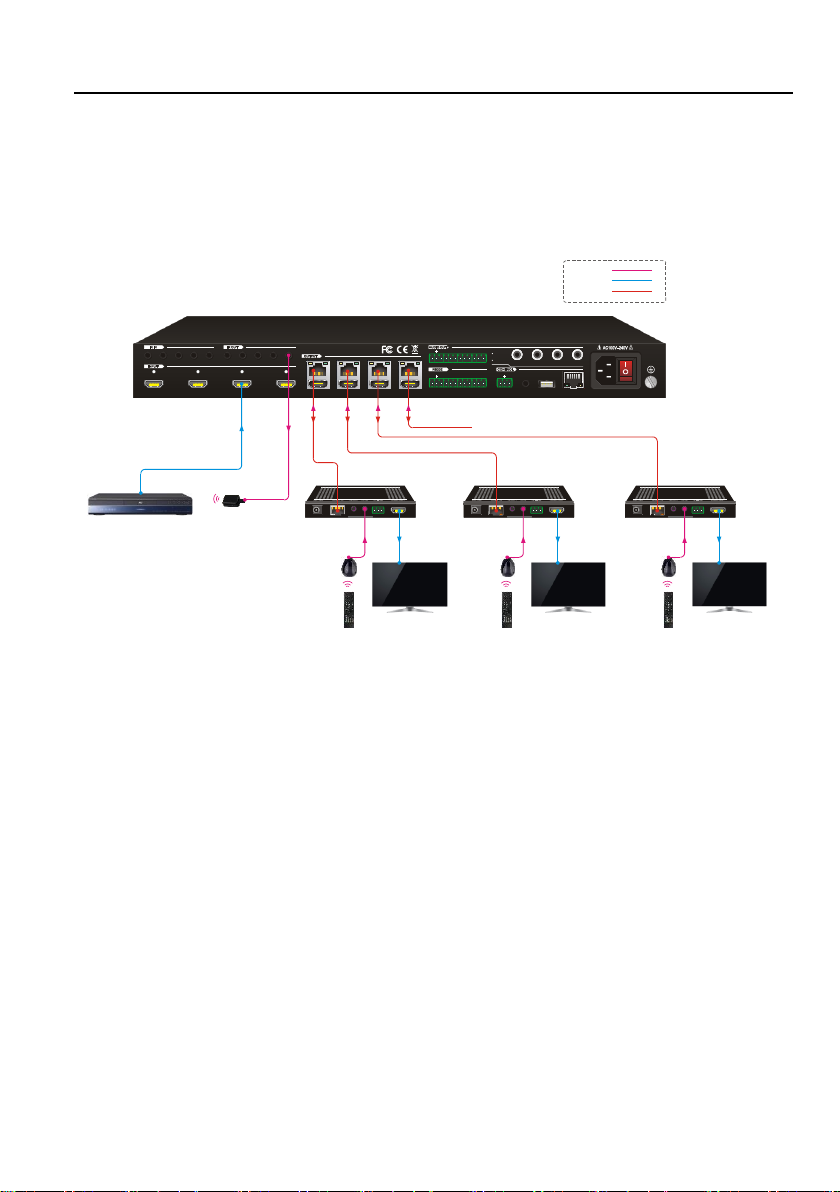
⚫ Control remote device through IR ALL IN port
The receiver can be connected to the IR ALL IN port on matrix to control all remote
output devices. In this case, the IR emitter must be connected to the IR OUT port on
each connected HDBaseT receiver, as shown in the diagram below:
Rece iver
Disp lay
IR Emi tter
Rece iver
Disp lay
IR Emi tter
Rece iver
Disp lay
IR Emi tter
Rece iver
Disp lay
IR Emi tter
4K Blu -Ray
4
1 2 3 4
L R
123 4
HDBaseT HDMI
1 2 3 4
Tx Rx
1 2 3 4
1 2 3 4 ALL IN 1 2 3 4 ALL OUT
IR EYERS232
Tx Rx
TCP/IP
Input
De-embedded
Output
De-embedded
FW1 2 3
IR Rec eiver
Disp lay Remo te
HDMI :
IR:
HDBa seT:

4x4 HDMI 2.0 Matrix Kit
22
7. GUI Control
The matrix also be controlled via TCP/IP. The default IP settings are:
IP Address:
192.168.0.178
Subnet Mask:
255.255.250.0
Type 192.168.0.178 in the internet browser, it will enter the below log-in webpage:

4x4 HDMI 2.0 Matrix Kit
23
7.1 Video Switching
Type the user name and password (both of them are “admin”), and then click Login to
enter the section for video switching.
Use the 4x4 button grid on the page to set which inputs are directed to which outputs.
For example, clicking the button on the Input 1 row and Output 2 column, directs input
1 to output 2.
Use the 9 numbered buttons under scene area to save and load layout presets.
• To save a given layout, first click one of the
numbered buttons, then click the Save button.
• To load a previously saved layout, first click one of
the numbered buttons, then click the Recall button.

4x4 HDMI 2.0 Matrix Kit
24
7.2 Coaxial Audio Control
Click Audio to enter the below section to select the digital audio from HDMI input or
HDBaseT output, and the audio can be mute or unmute by pressing the volume icon
on the right side.

4x4 HDMI 2.0 Matrix Kit
25
7.3 Configuration
The configuration section allows to manage HDCP compliance and the EDID settings.
Click HDCP to enter the below section to turn on/off HDCP compliance for every
output port.

4x4 HDMI 2.0 Matrix Kit
26
Click EDID Copy to enter the below section to copy the EDID data from a single output
port to input ports.
Operation:
1) Select one output port.
2) Select one or several input ports. Press ALL to select all input ports.
3) Press Confirm.

4x4 HDMI 2.0 Matrix Kit
27
Click EDID Setting to enter the below section to set a predefined EDID for input ports.
Operation:
1) Select a predefined EDID.
2) Select one or several input ports. Press ALL to select all input ports.
3) Press Confirm.
4x4 HDMI 2.0 Matrix Kit
28
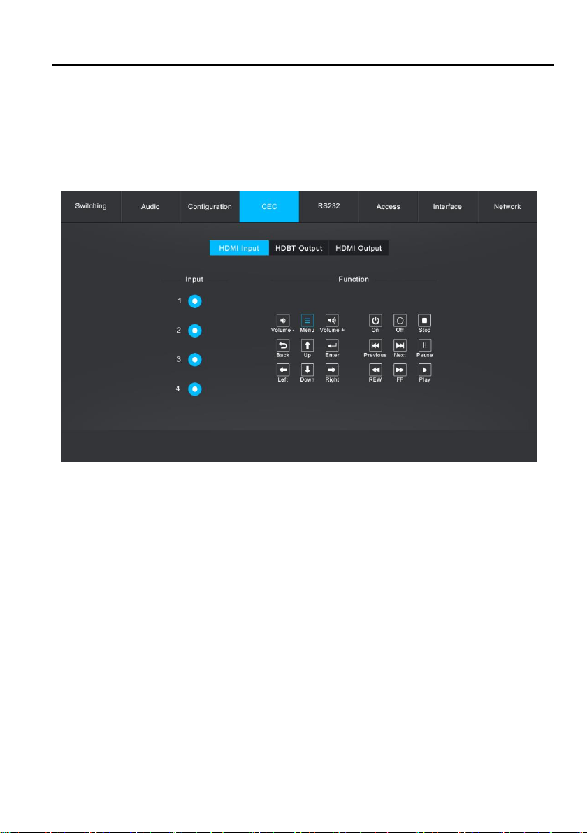
7.4 CEC Control
If the input sources, HDBaseT output devices and local HDMI output devices support
CEC, they can be controlled via the following CEC interface.
Click HDMI Input to enter the below section to control the selected input source.
4x4 HDMI 2.0 Matrix Kit
29
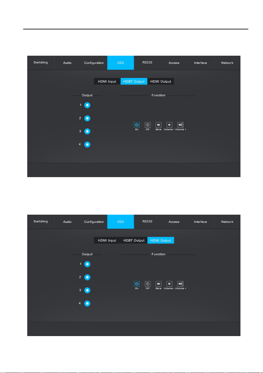
Click HDBT Output to enter the below section to control the selected HDBaseT output
device.
Click HDMI Output to enter the below section to control the selected local HDMI
output device.
4x4 HDMI 2.0 Matrix Kit
30
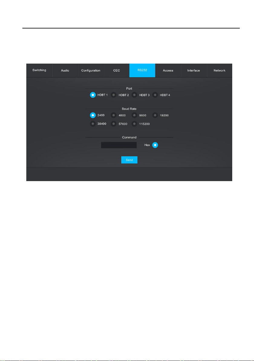
7.5 RS232 Control
Click RS232 to enter the below section to send RS232 commands to control remote
third-party device.
Operation:
1) Select the HDBaseT port which is connected with HDBaseT receiver which must
have third-party device attached.
2) Set the baud rate.
3) Typing the commands in the box to control the selected remote third-party device
which is connected to HDBaseT receiver. If click the Hex, the RS232 commands
can be typed with hexadecimal value.
4) Click Send to transmit RS232 command to the selected HDBaseT port.

4x4 HDMI 2.0 Matrix Kit
31
7.6 Access Setting
Click Access to enter the below section to reset password and lock or unlock front
panel buttons. Click Confirm to save any changes or click Cancel to cancel any
changes that have been made.
4x4 HDMI 2.0 Matrix Kit
32
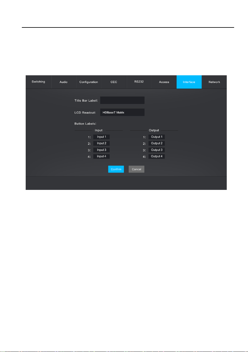
7.7 Interface Setting
Click Interface to enter the below section to modify title bar label, LCD readout and
button labels. Click Confirm to save any changes or click Cancel to cancel any
changes that have been made.
4x4 HDMI 2.0 Matrix Kit
33
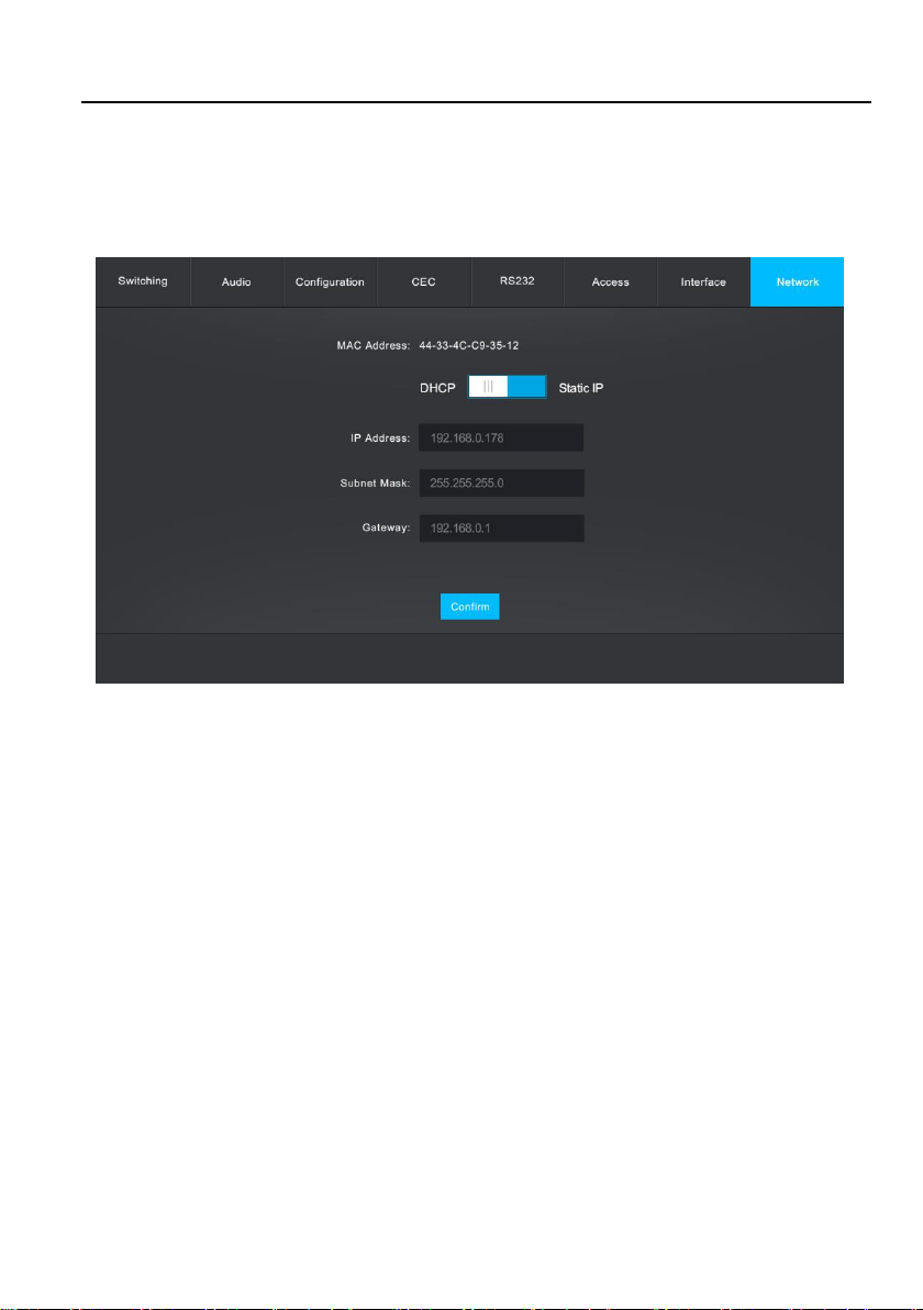
7.8 Network Setting
Click Interface to enter the below section to change the default IP Address, Subnet
Mask, and Gateway setting. Static IP or Dynamic Host Configuration Protocol (DHCP)
also can be chosen. Click the Confirm button to save any changes.

4x4 HDMI 2.0 Matrix Kit
34
7.9 GUI Upgrade
Please visit at http://192.168.0.178:100 for GUI online upgrade.
Type the username and password (the same as the GUI log-in setting, modified
password will be available only after rebooting) to login the configuration interface.
After that, click Administration in the source menu to get to Upload Firmware as
shown below:
Select the update file and click Apply button, and then it will start upgrade process.
4x4 HDMI 2.0 Matrix Kit
35
8. RS232 Control
8.1 RS232 Control Connection
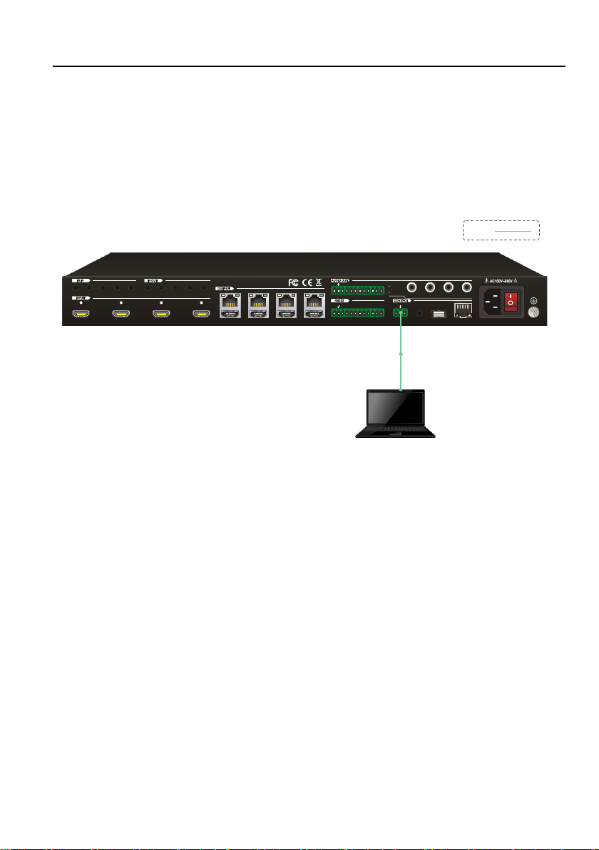
8.1.1 Control the Matrix from Local
To control the matrix from a local PC, the 3-pin to DB9 RS232 Cable is used to
connect between the matrix and PC. The connection diagram is shown as below:
4
1 234
L R
1
2
3
4
HDBase T HDMI
1 2
3
4
Tx Rx
1 234
1 234 ALL IN 1 234
ALL OUT
IR EYE
RS232
Tx Rx
TCP/IP
Input
De-embedde d
Output
De-embedde d
FW1 2
3
PC
RS2 32:

4x4 HDMI 2.0 Matrix Kit
36
8.1.2 Control the Matrix from Remote
To control the matrix from remote location, please connect one or more PCs to the
RS232 ports of HDBaseT receivers with the 3-pin to DB9 RS232 Cable. The matrix
can be controlled by any one of PCs, the connection diagram is shown as below:
Note: The command “RemoteCtrMcu[x].” (“x” is “1” or “0”) needs to be sent to enable
or disable this control mode. For example, send the command “RemoteCtrMcu1.” to
enable the remote-control mode, and send the command “RemoteCtrMcu0.” to
disable the remote-control mode for matrix.
4
1 234
L R
1
2
3
4
HDBase T HDMI
1 2
3
4
Tx Rx
1 234
1 234 ALL IN 1 234
ALL OUT
IR EYE
RS232
Tx Rx
TCP/IP
Input
De-embedde d
Output
De-embedde d
FW1 2
3
PC Dis play
Rec eiver
PC Dis play
Rec eiver
4K Blu -Ray
HDM I:
RS23 2:
HDB aseT:

4x4 HDMI 2.0 Matrix Kit
37
8.1.3 Control the Remote Third-party Device from Local
To control a third-party device from local, first determine which HDBaseT receiver is
connected to (1 in the diagram below). Next, connect a PC to the corresponding
RS232 port of matrix with 3-pin to DB9 RS232 Cable, then connect a third-party
device (e.g. projector) to the RS232 port of the determined HDBaseT receiver. The
remote third-party device can be controlled by the local PC, the connection diagram is
shown as below:
Proj ector
PC
Rece iver
4
1 234
L R
1
2
3
4
HDBaseT HDMI
1 2
3
4
Tx Rx
1 234
1 234 ALL IN 1 234
ALL OUT
IR EYE
RS232
Tx Rx
TCP/IP
Input
De-embedde d
Output
De-embedde d
FW1 2
3
4K Blu -Ray
HDMI :
RS23 2:
HDBa seT:

4x4 HDMI 2.0 Matrix Kit
38
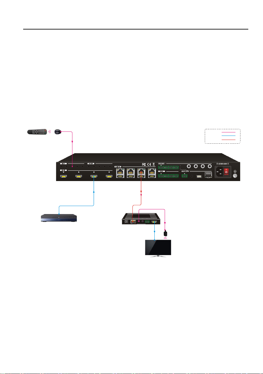
8.1.4 Control the Local Third-party Device from Remote
To control a third-party device from remote, first determine which HDBaseT receiver is
connected to (1 in the diagram below). Next, connect a PC to the RS232 port of
HDBaseT receiver with 3-pin to DB9 RS232 Cable, then connect a third-party device
(e.g. projector) to the corresponding RS232 port of matrix. The local third-party device
can be controlled by the remote PC, the connection diagram is shown as below:
PC
Rece iver
Proj ector
4
1 234
L R
1
2
3
4
HDBase T HDMI
1 2
3
4
Tx Rx
1 234
1 234 ALL IN 1 234
ALL OUT
IR EYE
RS232
Tx Rx
TCP/IP
Input
De-embedde d
Output
De-embedde d
FW1 2
3
4K Blu -Ray
HDMI :
RS23 2:
HDBa seT:

4x4 HDMI 2.0 Matrix Kit
39
8.2 RS232 Control Software
If the matrix and third-party devices needs to be controlled from PC by an RS232
connection, a RS232 control software should be installed in PC. Here using
CommWatch.exe as an example. The icon is shown as below:
Double-click the icon to run, and its interface is depicted below:
Parameter configuration area
Monitor area, show the commands
and its feedback information.
Command sending area

4x4 HDMI 2.0 Matrix Kit
40
8.3 RS232 Commands for Controlling Matrix
When controlling the matrix, the serial port settings for all RS232 commands is:
Baud rate: 9600 Data bit: 8 Stop bit: 1 Parity bit: none
The matrix can be controlled by sending the following RS232 commands:
8.3.1 System Command
Command
Description
Command Example and
Response
/*Type;
Report matrix model.
/*Type;
HDBaseT Matrix
/*Name;
Report matrix name
/*Name;
MP44
/%Lock;
Lock front panel buttons.
/%Lock;
System Locked!
/%Unlock;
Unlock front panel buttons.
/%Unlock;
System Unlock!
/^Version;
Report software version.
/^Version;
V1.0.0
Demo.
Switch to demo testing mode, switch AV 1->1,
2->2 and so on.
Demo.
Demo Mode
AV:01->01
IR:01->01
AV:01->02
IR:01->02
…
AV:04->04
IR:04->04
Undo.
Cancel the previous operation.
Undo.
Undo Ok!
PWON.
Power on the system.
PWON.
PWON
PWOFF.
Power off the HDBaseT power.
PWOFF.
PWOFF
STANDBY.
Turn the system to standby mode.
STANDBY.
STANDBY
%9961.
Report the system locking status.
%9961.
System Locked! /

4x4 HDMI 2.0 Matrix Kit
41
Command
Description
Command Example and
Response
System UnLock!
%9962.
Report the system power status.
%9962.
PWON / PWOFF /
STANDBY
RemoteCtrMcu[x].
Enable/disable the remote-control mode that the
matrix can be controlled from remote PC. x=1 or 0.
RemoteCtrMcu1
RemoteCtrMcu Open.
%0911.
Reset to factory default.
%0911.
Factory Default
8.3.2 Signal Switching
Command
Description
Command Example and
Response
[x]All.
Switch input [x] AV to all output. x=1~4.
1All.
01 To All.
All#.
Switch all input signal to their corresponding
output channel:
1->1, 2->2, 3->3, 4->4.
All#.
All Through.
All$.
Switch off all output.
All$.
All Closed.
[x]#.
Switch input [x] to output [x]. x=1~4.
1#.
04 Through.
[x]$.
Switch off output [x]. x=1~4.
1$.
01 Closed.
[x]@.
Switch on output [x]. x=1~4.
1@.
01 Open.
All@.
Switch on all outputs.
All@.
All Open.
[x]V[y].
Switch input [x] to one or several outputs [y],
separate output channels with comma). x=1~4,
y=1~4.
1V1, 2, 3.
AV:01->01,02,03
Status[x].
Report the input channel on output [x]. x=1~4.
Status1.
AV: 01->01
IR: 01->01
Status.
Report the input channel on output channel one by
one.
Status.

4x4 HDMI 2.0 Matrix Kit
42
Command
Description
Command Example and
Response
AV:01->01
IR:01->01
AV:02->02
IR:02->02
AV:03->03
IR:03->03
AV:01->04
IR:01->04
%9971.
Report the connection status of all inputs.
Y means the corresponding input port is
connected to a source device, N means not.
%9971.
IN 1 2 3 4
LINK Y Y Y Y
%9972.
Report the connection status of all outputs.
Y means the corresponding output port is
connected to an output device, N means not.
%9972.
OUT 1 2 3 4
LINK Y Y Y Y
%9975.
Report the switching status.
%9975.
Out 01 02 03 04
In 01 02 03 01
8.3.3 Preset Management
Command
Description
Command Example and
Response
Save[y].
Store the current switching status to present [y].
y=1~ 9.
Save3.
Save To F3
Recall[y].
Recall present [y]. y=1~ 9.
Recall1.
Recall From F1
Clear[y].
Clear the present [y]. y=1~ 9.
Clear1.
Clear F1

4x4 HDMI 2.0 Matrix Kit
43
8.3.4 Output Audio Control
Command
Description
Command Example and
Response
COAX[x][MU/UM].
Mute or unmute the coaxial audio output [x]. x=
01~04. Use MU for mute or UM for unmute.
COAX01MU.
COAX01MU.
AnlogAudio[x][M
U/UM].
Mute or unmute the analog audio output [x]. x=
01~04. Use MU for mute or UM for unmute.
AnlogAudio01UM.
AnlogAudio01UM.
%9977.
Report the output audio status.
%9977.
COAX01O.
COAX02O.
COAX03O.
COAX04O.
COAX01UM.
COAX02UM.
COAX03UM.
COAX04UM.
AnlogAudio01UM.
AnlogAudio02UM.
AnlogAudio03UM.
AnlogAudio04UM.
8.3.5 EDID Configuration
Command
Description
Command Example and
Response
EDIDH[x]B[y].
Set the EDID data of output [x] to input [y]. If the
EDID data is available and the audio part supports
not only PCM format, then force-set it to only
support PCM. If the EDID data is not available, it
will set to initial EDID.
x=1~4, y=1~4.
EDIDH1B4.
EDIDH1B4
EDIDPCM[x].
Set the audio format of input [x] to PCM. x=1~4
EDIDPCM4.
EDIDPCM4
EDIDG[x].
Report the EDID data from output [x].
x=1~4.
EDIDG2.
EDIDMInit.
Reset factory default EDID to all input ports.
EDIDMInit.
EDIDMInit.
EDIDM[x]B[y].
Set the EDID data of output [x] to input [y]. If the
EDID data is not available, the matrix will set it to
EDIDM1B4.

4x4 HDMI 2.0 Matrix Kit
44
Command
Description
Command Example and
Response
initial EDID data.
x=1~4, y=1~4.
EDIDM1B4
EDIDUpgrade[x].
Upgrade the EDID data of the input port [x]. When
the command applied, system prompts to upload
the EDID file (.bin). Operation will be cancelled in
10 seconds.
EDIDUpgrade1.
EDID/[x]/[y].
The input [x] recall the embedded EDID [y]. x=1~4,
y=1~7.
1) 720p 2D PCM/DTS/Dolby
2) 720p 3D PCM/DTS/Dolby
3) 1080p 2D PCM
4) 1080p 3D PCM/DTS/Dolby
5) 4K@30Hz PCM/DTS/Dolby
6) 4K@60Hz 4:2:0 PCM/DTS/Dolby
7) 4K@60Hz 4:4: PCM/DTS/Dolby
EDID/1/0.
EDID/1/0
UpgradeIntEDID[y
].
Upgrade the embedded EDID [y].
y=1~7.
When the matrix gets the command, it will show a
message to send EDID file (.bin file).
UpgradeIntEDID3
GetInPortEDID[x].
Report the EDID of input [x]. x=1~4
GetInPortEDID1.
GetIntEDID[x].
Report the embedded EDID [y].
y=1~7.
GetIntEDID6.

4x4 HDMI 2.0 Matrix Kit
45
8.3.6 HDCP Compliance
Command
Description
Command Example and
Response
/%O/[X]:[Z].
HDCP management command.
The O is the output port; the X is the number of
output port, and Z is for HDCP compliance status.
X=01~04 or ALL, Z= 0 (Off) or 1 (On).
/%O/01:1.
/%O/1:1.
%0801.
Auto HDCP management mode.
%0801.
0801%
%9973.
Report the HDCP status of all input ports.
Y means the input AV signal is transferred with
HDCP, N means not.
%9973.
In 01 02 03 04
HDCP Y Y Y Y
%9974.
Report the HDCP status of all output ports.
Y means the output AV signal is transferred with
HDCP, N means not.
%9974.
Out 01 02 03 04
HDCP Y Y Y Y
8.3.7 Baud Rate Setting
To ensure the bi-directional RS232 communication, the serial baud rate of matrix
should be set as the same as the RS232 ports’ on remote HDBaseT receivers.
Command
Description
Command Example and
Response
Baudrate 2400.
Set the serial baud rate of matrix as 2400.
Baudrate 2400.
Set Local RS232 baudrate
is 2400!
Baudrate 4800.
Set the serial baud rate of matrix as 4800.
Baudrate 4800.
Set Local RS232 baudrate is
4800!
Baudrate 9600.
Set the serial baud rate of matrix as 9600.
Baudrate 9600.
Set Local RS232 baudrate is
9600!
Baudrate 19200.
Set the serial baud rate of matrix as 19200.
Baudrate 19200.
Set Local RS232 baudrate is
19200
Baudrate 38400.
Set the serial baud rate of matrix as 38400.
Baudrate 38400.
Set Local RS232 baudrate is
38400!
Baudrate 57600.
Set the serial baud rate of matrix as 57600.
Baudrate 57600.

4x4 HDMI 2.0 Matrix Kit
46
Set Local RS232 baudrate is
57600!
Baudrate 115200.
Set the serial baud rate of matrix as 57600.
Baudrate 115200.
Set Local RS232 baudrate is
115200!
8.3.8 CEC Control
If the input sources, HDBaseT output devices and local HDMI output devices are
supports CEC, they can be controlled by sending the following command instead of IR
remote.
CEC[I/O][port][command].
⚫ The “[I]” represents the input port. The “[O]” represents the output port.
⚫ The “[port]” represents the port number. The local HDMI output ports are 01~04
and the HDBT output ports are 05~08. The HDMI input ports are 01~04.
⚫ The “[port]” is “FF” for sending command to all input or output ports.
⚫ The “[command]” represents the specific command from the table below.
✓ Control the input source:
Command
Description
Command Example and Response
CECI[port]00.
Confirm operation (Enter).
CECI0100.
CEC_IN_01_SEND_SUCCESS!
CECI[port]01.
UP.
CECI0101.
CEC_IN_01_SEND_SUCCESS!
CECI[port]02.
DOWN.
CECI0102.
CEC_IN_01_SEND_SUCCESS!
CECI[port]03.
LEFT.
CECI0103.
CEC_IN_01_SEND_SUCCESS!
CECI[port]04.
RIGHT.
CECI0104.
CEC_IN_01_SEND_SUCCESS!
CECI[port]0A.
Enter main menu.
CECI010A.
CEC_IN_01_SEND_SUCCESS!
CECI[port]0D.
Exit menu.
CECI010D.
CEC_IN_01_SEND_SUCCESS!
CECI[port]41.
Volume up.
CECI0141.

4x4 HDMI 2.0 Matrix Kit
47
CEC_IN_01_SEND_SUCCESS!
CECI[port]42.
Volume down.
CECI0142.
CEC_IN_01_SEND_SUCCESS!
CECI[port]43.
Mute
CECI0143.
CEC_IN_01_SEND_SUCCESS!
CECI[port]44.
Play.
CECI0144.
CEC_IN_01_SEND_SUCCESS!
CECI[port]45.
Stop.
CECI0145.
CEC_IN_01_SEND_SUCCESS!
CECI[port]46.
Pause.
CECI0146.
CEC_IN_01_SEND_SUCCESS!
CECI[port]48.
Rewind.
CECI0148.
CEC_IN_01_SEND_SUCCESS!
CECI[port]49.
Fast forward.
CECI0149.
CEC_IN_01_SEND_SUCCESS!
CECI[port]4B.
Forward.
CECI014B.
CEC_IN_01_SEND_SUCCESS!
CECI[port]4C.
Backward.
CECI014C.
CEC_IN_01_SEND_SUCCESS!
CECI[port]6C.
Power off.
CECI016C.
CEC_IN_01_SEND_SUCCESS!
CECI[port]6D.
Power on.
CECI016D.
CEC_IN_01_SEND_SUCCESS!
✓ Control the output display device:
Command
Description
Command Example and Response
CECO[port]41.
Volume up.
CECO0141.
CEC_OUT_01_SEND_SUCCESS!
CECO[port]42.
Volume down.
CECO0142.
CEC_OUT_01_SEND_SUCCESS!
CECO[port]43.
Mute
CECO0143.
CEC_OUT_01_SEND_SUCCESS!
CECO[port]6C.
Power off.
CECO016C.
CEC_OUT_01_SEND_SUCCESS!
CEO[port]6D.
Power on.
CECO016D.
CEC_OUT_01_SEND_SUCCESS!
4x4 HDMI 2.0 Matrix Kit
48
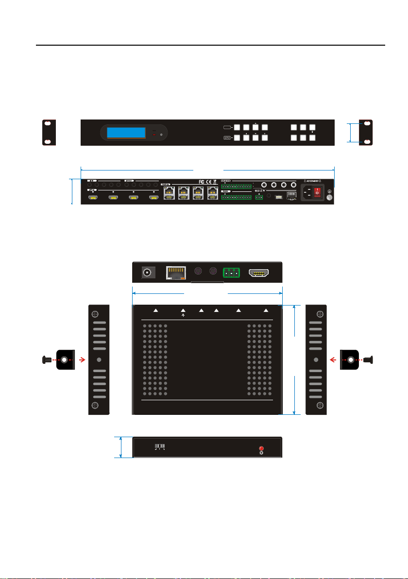
9. Panel Drawing
9.1 HDBaseT 4x4 HDMI 2.0 Matrix
9.2 HDBaseT Receiver
4
1 2 3 4
L R
123 4
HDBaseT HD MI
1 2 3 4
Tx Rx
1 234 ALL IN 1 234
ALL OUT
IR EYERS232
Tx Rx
TCP/IP
Input
De-embedded
Output
De-embedded
FW1 2 3 1 2 3 4
ALL ENTE R R ECALL
CLEAR EDID
1 2 3 4
1 2
3 4
INPUT
PWR
IR
44 mm
436.4 mm
32 mm
DC 12V
Tx
Rx
H
D
M
I
O
U
T
HDBT I N
I
R
O
U
T
I
R
IN
CTRL
UPDATE B UPDATE A
115 mm
84 mm
16 mm

4x4 HDMI 2.0 Matrix Kit
49
10. Troubleshooting & Maintenance
Problems
Potential Causes
Solutions
Output image with
snowflake.
Bad quality of the
connecting cable.
Try another high-quality cable.
Fail or loose connection.
Make sure the connection is
good.
No output image when
switching.
No signal at the input /
output end.
Check with oscilloscope or
multimeter if there is any signal
at the input/ output end.
Fail or loose connection.
Make sure the connection is
good.
The product is broken.
Send it to authorized dealer for
repairing.
POWER indicator
doesn’t work or no
respond to any
operation.
Fail connection of power
cord.
Make sure the power cord
connection is good.
EDID management does
not work normally.
The HDMI cable is
broken at the output end.
Change for another HDMI
cable which is in good working
condition.
Static becomes stronger
when connecting the
video connectors.
Bad grounding.
Check the grounding and
make sure it is connected well.
Cannot control the
device by control device
(e.g. a PC) through
RS232 port.
Wrong RS232
communication
parameters.
Type in correct RS232
communication parameters.
Broken RS232 port.
Send it to authorized dealer for
checking.
Cannot control the
device by front panel
buttons while can control
it through RS232 port
The front panel buttons
are locked.
Send command /%Unlock; to
unlock the front panel buttons.
Note: If your problem still remaining after following the above troubleshooting steps,
please contact your local dealer or distributor for further assistance.

4x4 HDMI 2.0 Matrix Kit
50
11. Customer Service
The return of a product to our Customer Service implies the full agreement of the
terms and conditions hereinafter. There terms and conditions may be changed without
prior notice.
1) Warranty
The limited warranty period of the product is fixed three years.
2) Scope
These terms and conditions of Customer Service apply to the customer service
provided for the products or any other items sold by authorized distributor only.
3) Warranty Exclusions:
⚫ Warranty expiration.
⚫ Factory applied serial number has been altered or removed from the product.
⚫ Damage, deterioration or malfunction caused by:
✓ Normal wear and tear.
✓ Use of supplies or parts not meeting our specifications.
✓ No certificate or invoice as the proof of warranty.
✓ The product model showed on the warranty card does not match with the
model of the product for repairing or had been altered.
✓ Damage caused by force majeure.
✓ Servicing not authorized by distributor.
✓ Any other causes which does not relate to a product defect.
⚫ Shipping fees, installation or labor charges for installation or setup of the
product.
4) Documentation:
Customer Service will accept defective product(s) in the scope of warranty
coverage at the sole condition that the defeat has been clearly defined, and upon
reception of the documents or copy of invoice, indicating the date of purchase, the
type of product, the serial number, and the name of distributor.
Remarks: For further assistance or solutions, please contact your local distributor.

4x4 HDMI 2.0 Matrix Kit
51
www.GeMNeXT.com
GeMNeXT rights owned by AVDIS B.V.
Tel: +31 (0)85 2100 614
Email: info@gemnext.com
Website: www.gemnext.com
Ambachtstraat 3A
3732 CN De Bilt
The Netherlands
 Loading...