

Page 1

Installation Manual
For
Contact us at (732) 286-9496 or E-mail info@avcon.com with questions during the installation process.
Our service team is available Mon-Fri 7:30am-4pm.
Rev. 12-11-21
Page 2
2
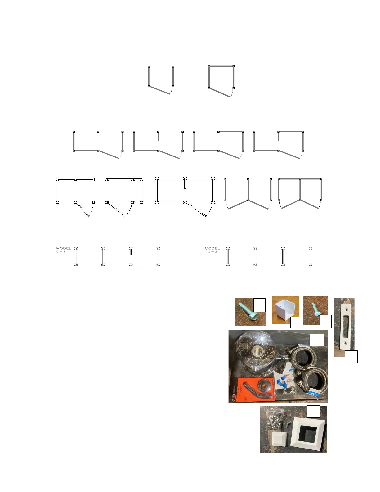
Floor Model Options
Tools Required: Tape Measure, Screw Gun, Level, Pencil, 1/2” Socket Wrench and Silicone.
Hardware Box Includes:
1. Tek Screws for Double or Cabana Frame Installation
2. Post Brackets for Wall Panel Installation
3. Bag of white self-drilling ¾” stainless steel screws
4. Strike Plate for Door Installation
5. Shower Trim Wall Accessories (ONLY IF ORDERED)
Shower Head & Neck
a. Braided Hoses
b. Cut Post Brackets
c. Clevis Pin
d. Winterization Instructions
6. Attached to the Posts: post flange, post cap and hex bolts.
Single Models Size: 46”d x 46”w x 88”h, 36”d x 36”w x 88”h - 89 1/2”h with roof
Model S-1
Model S-2
Double Models Size: 46”d x 88”w x 88”h, 36”d x 68”w x 88”h – 89 ½”h with roof
Model D-1
Model D-2
Model D-3
Model D-5
Model D-7
Model D-4
Model D-8
Cabana Models Size: 46” d x 130”w x 88”h, 36”d x 100”w x 88”h – 89 ½”h with roof
Model D-560
Model D-6
1
2
3
4
5
6
Page 3

3
Before beginning installation determine what the unit is to be mounted onto. There are 3 options:
1. Directly onto a concrete surface, pavers or decking using aluminum base frame(s).
a. See install instructions “A” below (page 3).
2. Directly onto concrete, pavers, or decking without using the AVCON base frame(s)
a. See install instructions “B” below (page 3).
3. Directly onto the ground, sand, or any similar surface, using the AVCON Base Frame(s).
a. See install instruction “C” below (page 4).
Install Instruction “A” Concrete Base Mounting
1. Position Base Frame in desired location and position. Ensure sufficient clearance behind unit for
plumbing fixtures, hose bibs, water lines, etc. (See Instructions #2 Floor Frames - Pic. 2a & 2b)
2. Use appropriate masonry anchors to fasten the base frame into the concrete base or lags if
mounting onto decking.
a. Note: If mounting onto pavers, ensure there is sufficient base material beneath the pavers
to support unit and to prevent wind loads from toppling or moving unit.
b. It is necessary to install blocking when mounting onto decking.
3. Proceed to “Post Bracket Installation (See Instructions #1 Post Bracket Installation).
Install Instructions “B” (NO Base Frame)
1. Note: It is important for spacing between posts to be as specified below to ensure wall panels
and door fits correctly in opening. This step will require post brackets to be installed.
a. Note: A 36” single, double or Cabana the spacing from inside edge to inside edge between
all posts is 29.75”. For a 46” single, double or Cabana unit the spacing from inside edge to
inside edge of all posts is 39.75”.
b. It is recommended that wall panels be joined to posts before mounting onto pad or pavers.
This will require completion of the installation of all post brackets. (See Instructions #1 Post
Bracket Installation). There are four posts for a single - six posts for a double – eight posts
for a cabana unit. Next comes installing the wall panels to the post(s). (See Instructions #4
Wall Panel Installation).
c. The section chosen for the door opening and the section chosen for the removable shower
wall with faucets will require a single “U” channel header to be placed between adjoining
posts at the top. This will assist in maintaining proper spacing. (See Instructions #1d &
Instructions #5 for Proper Installation).
d. Once panels and headers are attached, position unit into place.
e. Before anchoring ensure all posts are plumb vertically and spaced identically apart between
posts.
f. Anchor posts using the appropriate anchors or lags in each of the holes in the base
plate. Shim as required to keep posts level and plumb.
g. Proceed to (Instructions #6 – Half Wall Panel Installation) for Half Wall Panel – If
none proceed to (Instructions #7 – Door Installation) for Door Installation.
Page 4
4
Install Instructions “C” French Drain Installation
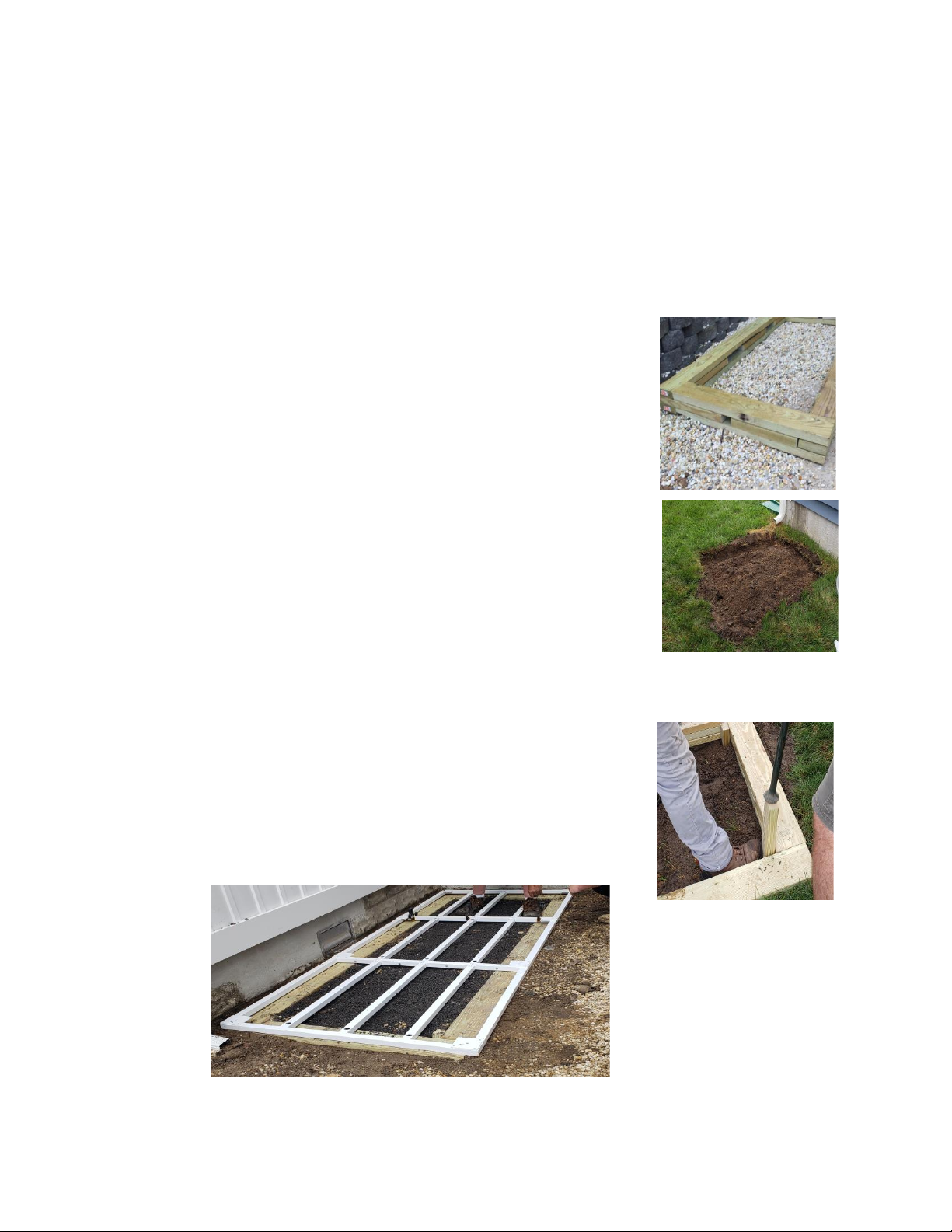
1. Note: You will need a 6”x6” base to mount the AVCON Base Frame onto. This will require 2”x6”
treated lumber (for ground contact) stacked on top of each other creating a nominal 6” x 6”
support foundation. 3” or Greater Deck screws will be used to screw the 2x6 boards together.
See figure illustrations below.
2. The finish perimeter of the base foundation should match aluminum base frame. See list below:
a. 36” Single: 35” x 35” 46” Single 45” x 45”
b. 36” Double 35” x 66.75” 46” Double 45” x 86.75”
c. 36” Cabana 35” x 98.5” 46” Cabana 45” x 128.5”
3. It is recommended that corners of the lumber be staggered creating
an overlap between boards. (See Pic 3). Prior to final screwing of
board use a carpenter square to ensure corners are 90 degrees.
4. Once wood base is finished position exactly where unit is to be
installed. Trace perimeter of wood base.
5. Move base aside and excavate ground approximately 5” deep so
that top of wood base is flush with surrounding ground. Use excess
dirt removed to grade around outside perimeter of wood base. (See
Pic. 5)
6. Using “stakes” cut from excess lumber or other materials, drive
stakes into ground at least 24”. There should be 4 each at each
inside corner and 6 each for a double. Top of stakes should be flush
or slightly below top of wood frame. (See Pic. 6)
7. Using level and shovel or pry bar, lift or lower each corner of base
one at a time until level. Use deck screws through stakes into wood base to keep frame level.
8. It is recommended an addition hole 1’ deep be dug inside area directly beneath where shower is
to be installed for drainage.
9. Fill the interior with 3/8” stone for a French drain. * 6x6 base should
be FLUSH/LEVEL to pavers or grade.
10. Position AVCON aluminum frame on top of wood base. (See
Instructions # 2 Floor Frame Installation). (See Pic. 10)
11. Secure the aluminum base frame to the wood foundation frame
using wood lags through holes provided in base frame.
Pic. 3
Pic. 6
Pic.5
Pic. 10
Pic. 10
Page 5
5
1. Post Bracket Installation:
*Note: The Post Brackets get secured to the posts which support the wall panels. Get together all posts
(4 for single – 6 for double – 8 for cabana). To determine location of each bracket, it is important to
know your floor plan of the unit. (See Floor Model Options Page 2) Determine the door location and
door swing, and location of the panel containing the shower trim set (assuming the unit has a shower
section).
a. Install Flange Cover on each post before installing any of the support brackets.
b. Determine how many outside corner posts are needed in the unit you are installing
by laying out the posts as per the floor plans of your unit found on page 2.
c. Sections where the door is to be installed and/or where there will be an open panel
will not have lower brackets. A header will be installed from post to post on the top
only in these areas.
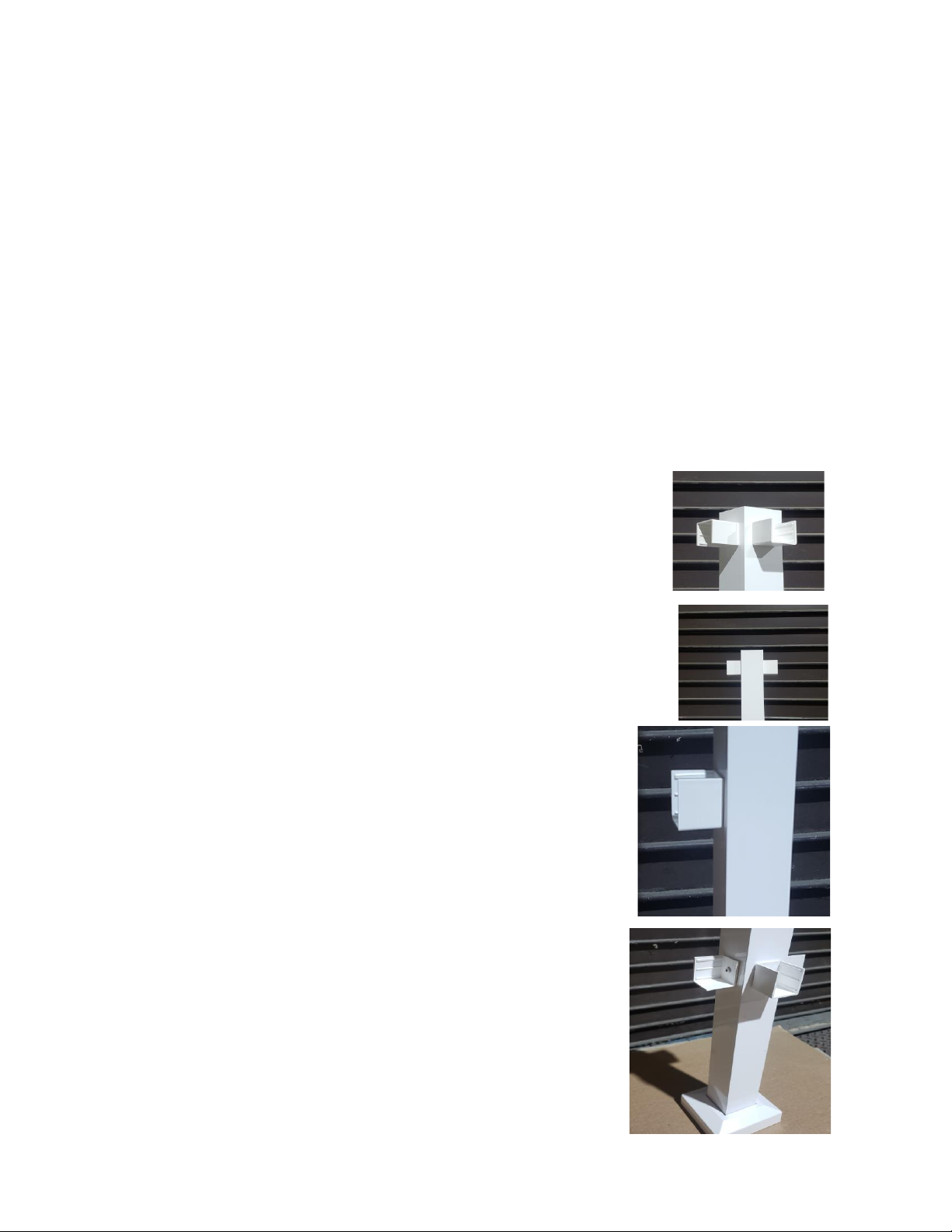
d. From top of post measure down 2.5” and mark a line. This will be the bottom of the
brackets. The slot in the bracket should be on the post. Brackets should be installed
face down for each section which will have a wall panel. Brackets should face up
over the door and any sections without a wall panel and for
the wall panel which will have the shower head (assuming
you are having a shower trim panel).
1. Corner posts brackets should be attached at 90
degrees. (See Pic. 1a)
2. In-line post brackets should be attached at 180
degrees to each other. (See Pic. 1b)
e. Center the bracket on post and install with white ¾” stainless
steel self-drilling screws provided.
f. To secure the post brackets to the bottom of the posts
for the wall panel sections, measure from the bottom
of the top bracket down the post 71” and draw a line.
This is the bottom of the lower bracket (See Pic. 1c)
Install with the bracket open end facing up. Note: if a
Cabana wall is being installed bottom measurement
will be 79”.
1. At this time install the post bracket for the shower
wall (NOTE: this bracket has an open side as well to
accept the shower wall panel at the bottom of
the post as seen in the picture below. (See Pic. 1d)
2. The posts where the door will be hung will not
have a lower bracket on either post.
3. Any posts where there is no wall panel will not
have a lower bracket
Pic. 1a
Pic. 1b
Fig. 1c
Fig. 1d
Pic. 1c
Pic. 1d
Page 6
6
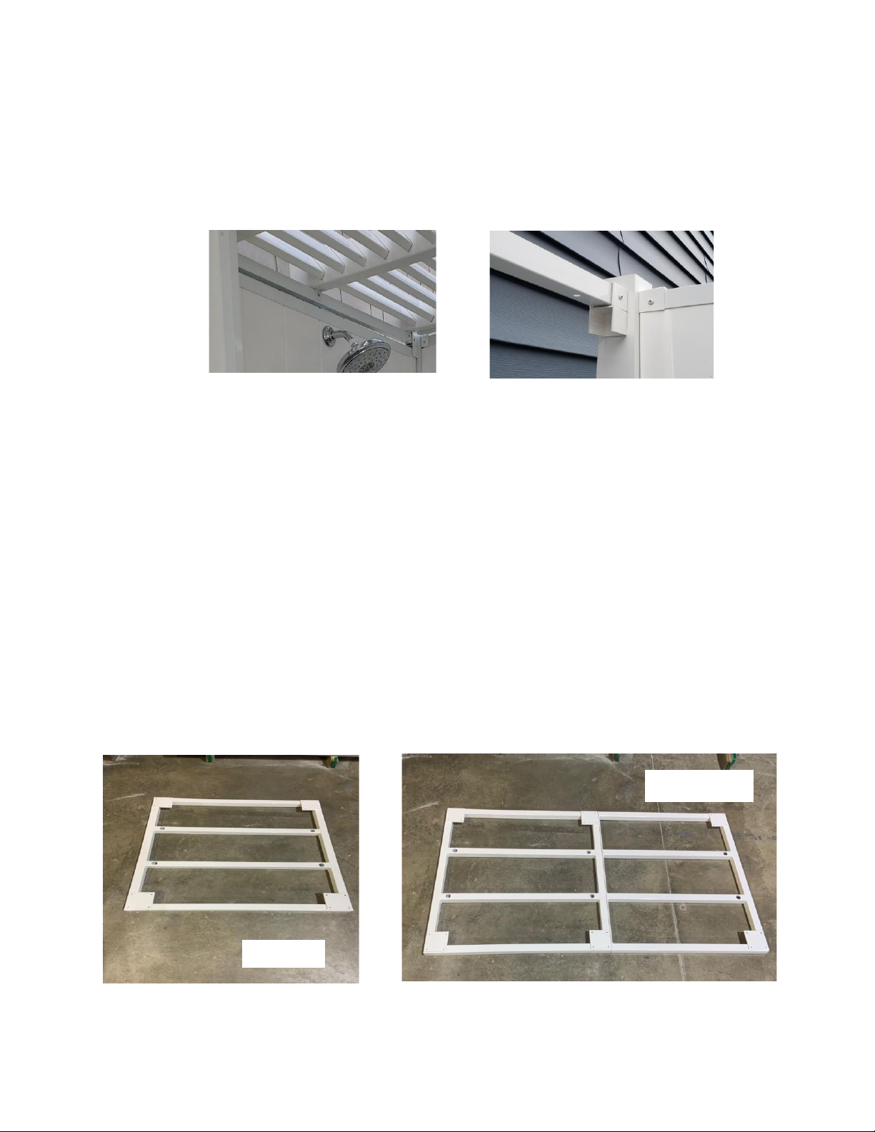
g. The shower trim panel is designed to be removable. This wall panel is shorter than
the others and requires a second “header” channel, open end facing down and
directly beneath the top two previously installed brackets. (See Pic. 1e). The
uppermost 2 brackets on each post should have the open side facing up. Immediately
below the top brackets, install 2 post brackets with the opening facing down. (See
Pic. 1f)
2. Floor Frame(s) Installation: (*Skip this section if there is no frame)
a. For a single unit proceed with placing frame into position. (See Pic. 2a) (36” has 2
interior supports – 46” has 3 interior supports). Use appropriate screws to secure the
base to the surface through center holes.
b. For double or cabana units proceed with attaching expander frame to main frame. (See
Pic.2b) The expander frame will have a flat bar on one side rather than square tubing.
c. Using self-drilling Tex screws provided join the frames together with one screw in
between each vertical supports.
d. Ensure the floor support member run parallel to each other. See below
e. Once you have joined the frames together lay frame into position with posts support
plate facing up. Use a level to make sure frame is level on all four sides and the
middle. Do this on the outside of frame and inner supports. Use shims to level if
necessary. Secure base to the ground surface.
Pic. 1e
Pic. 1f
Pic. 2a
Pic. 2b
Page 7
7
3. Post Installation:
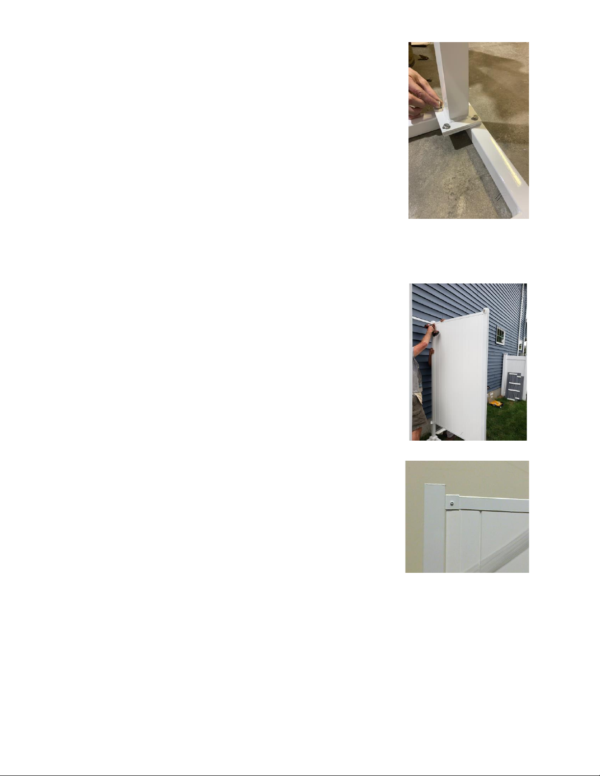
a. Position the posts on the square plates. Lift the flange
cover to finger tighten the 5/16” x ¾” Hex bolts in the predrilled and pre-tapped holes. NOTE: * The elongated holes
at the base of the post must be parallel with the door
opening. It is important to establish where the door will
be at this time if you have not done so already.
4. Wall Panel Installation:
*If you purchased Shower Valve Trim Set with removable wall panel, See Instructions #5 on
how to install the removable panel. *
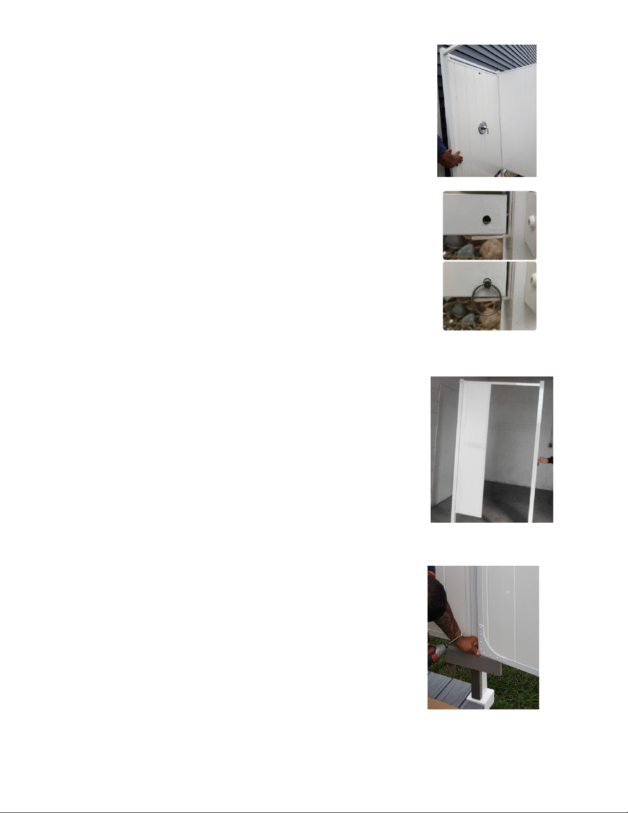
a. Set the wall panel into the bottom brackets first, and then pull the
posts away at the top. You will see tape on the side or the panel
edge U channel. Remove the protective cover before fully
engaging the panel into post brackets. The top of the wall panel
should fit snug in the upper brackets. If not, simply loosen the
base plate bolts until you can position the wall panel into the
bracket.
b. Next, fasten the wall panel to the brackets using the white self-
drilling ¾” stainless steel screws on all four corners of the wall
panel. *All screws must be facing the interior of the shower &
centered on bracket. (Fig. 4a&b).
c. Continue this process until all wall panels are installed. If there is
any part of the shower where the existing structure is used as the
rear wall, and a wall panel is not being installed, a header will be
provided for you to secure the two posts. (See Fig. 1f) A header
will also be installed on the top of the door opening and above
the shower trim removable panel section. Attach the header
(OPEN SIDE UP) to the brackets using white self-drilling ¾”
stainless steel screws.
PIC 1c
PIC 2c
PIC 2a
Fig. 4a
Fig. 4b
Fig. 4a
Page 8
8
5. Removable Panel Installation:
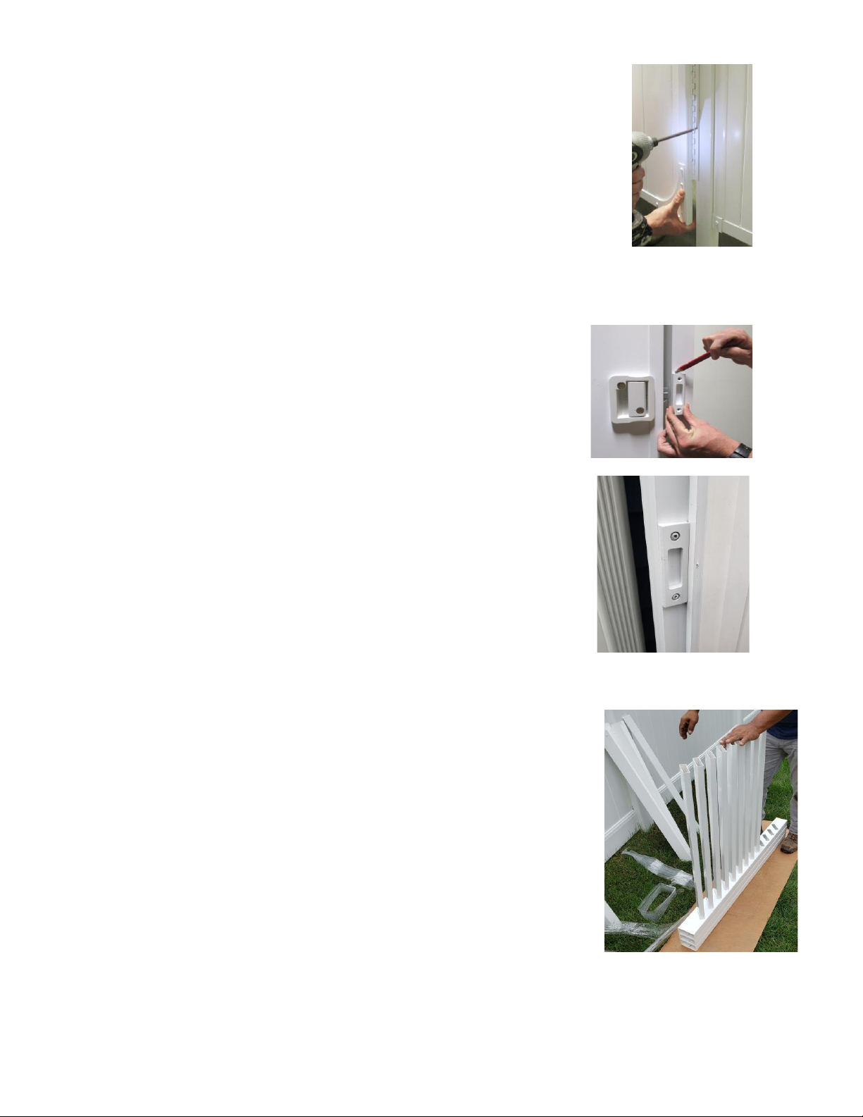
a. Install panel, top first, into the lower downward facing U
post brackets which was previously installed directly below
the main header in (Instruction #1g). You will have two
headers, one over the other. The top will have open end up
and the 2nd header immediately below the first will be open
end down. (See Pic. 5a)
b. Install bottom removable panel into the lower brackets.
These brackets will have one side open. (See Fig. 1d) Rest
panel into these brackets.
c. Drill ¼” hole on bottom of the panel and brackets far side of
the brackets. (See Pic. 5b)
d. Install clevis pins. This will be done on both sides. (See Pic.
5c.)
6. Half Wall Panel Installation (Double Units Only):
a. Install post brackets on both center posts, each facing toward
center of unit. As in original brackets installation
(Instructions #1), mark a line 2.5” from top of post. This
will be the bottom of the brackets.
b. Install a header channel between the center posts
connecting the two. Opening facing down.
c. Install a third post bracket on bottom of rear post ONLY
(71.5” below the top bracket).
d. Install the half wall panel up into the header on top and
post bracket on the bottom of post.
e. Fasten 2 white self-drilling ¾” stainless steel screw through
the header into the top of the half wall and the bottom bracket. (See Fig. 4b)
7. Door Installation:
a. A header should have been previously installed between
posts in door opening. If not, you should do so now.
b. Determine door swing and proper side for hinge
attachment.
c. Enlist help to align bottom of door flush with adjoining
panel or cut blocking (i.e., 2 x 4” wood) so that the door,
when resting on the blocking, is flush with the bottom of
the adjoining panel. (See Pic. 7a)
PIC 3c
Pic. 5a
Pic. 5b
Pic. 7a
Page 9
9
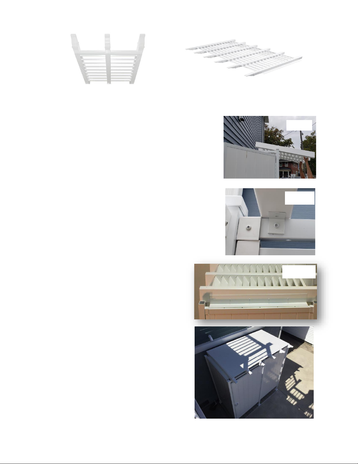
d. Position door so the hinge barrel pin (attached to the door) is
evenly aligned with post edge and on the outside corner edge of
the post. This will ensure that the door will be flush when fully
closed. (See Pic. 7b)
e. Hinge flange should lay flat on door opening side of the post.
f. Install white self-drilling ¾” stainless steel screw in each pre-
drilled hole on the hinge ensuring that the hinge is straight on the
post. *The bottom of the door should align with the bottom of
adjacent wall panels.
8. Strike Plate Installation:
a. Hold the door in the closed position and mark the
proper location to attach the strike plate. (See Pic. 8a)
b. Attach the strike plate using two white self-drilling ¾”
stainless steel screws. Make sure edge is flush with
front edge of post and the beveled edge is on the
outside so the door closes properly.
c. Attach the door stop to the post behind the strike plate.
It is important to have the center hole of doorstop align
with the middle of the strike plate. (See Pic. 8b)
*IMPORTANT: YOU ARE READY TO ADJUST POSTS FOR EQUAL REVEAL
ONCE PLUMB. TIGHTEN THE POST BOLTS TO THE FRAME. Make sure the
door closes properly and is sitting level.
9. Roof Installation:
*2 people are recommended for this step. If unit is being
Installed against a structure, install post caps to the top of the
posts prior to installing the roof. (See Instructions #10).
a. Assemble the roof on the ground by sliding the louvers
into the rails. Determine the direction you would like the
louvers to go prior to sliding them on for privacy purposes.
(See Pic. 9a)
b. If you are using the pergola end caps it is important to use
silicone or PVC cement to secure them to the cross beams in
the front of the shower (door side). Secure the flat caps with
silicone to the back side of the cross beams.
Pic. 8a
Pic. 7b
Pic. 8b
PIC 9a
Page 10
10
c. With one person standing inside the shower to
guide and support the roof, lift the roof, and slide it
into place. (See Pic. 9c) Make sure the back of the
cross beams is flush with the base frame before
proceeding. The end cross beams should sit just
inside your top post brackets. (See Pic. 9d)
Dependent on unit size, space the center cross
beams evenly. (See Pic. 9b)
d. Use the L brackets and white self-drilling ¾” stainless
steel screws to attach each cross beam to the inside
of a wall panel or header on both the front and rear
of the shower. (See Pic 9d)
e. It is time to secure the privacy bracket on
either side of the roof. Place the drilled holes
against cross beams. Center it to where it
should be (approximately 5” on either side).
Use white self-drilling ¾” stainless
steel screws in the pre-drilled holes to
secure the privacy bracket to the
louvered roof. (See Pic. 9e)
f. For Solid Roof Installation, (you will
not receive the louvers; just cross
beams) install the support beams
first (see item “d” above. Place the
PVC sheet on top of the support
beams. Use the Stainless 1” selfdrilling steel screws to secure the roof.
(See Pic. 9f)
Pic. 9b
Pic. 9d
Pic. 9d
Pic. 9e
Pic. 9f
Page 11
11
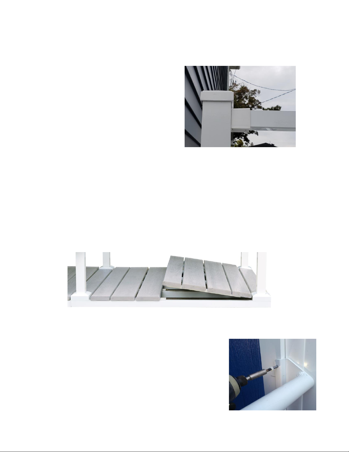
10. Post Cap Installation:
a. Use silicone to secure the post cap to
the top of the post. (See Pic. 10a.)
11. Decking Installation:
a. For a single base frame start at either edge of the frame, lay one of the pre-assembled
floor panels in place; followed by the matching interlocking panel. Note the floor planks
should run perpendicular to the frame joists. (See Pic. 11a)
b. For the expander frame the floor panel with the smaller plank is on the farther side
away from the single base side. Install the remaining floor panel in the open space next
to the single base floor frame.
12. Towel Bar/Hook Bar Installation:
*Note: Towel Bar usually sits 54” above decking, however can
install at any height. Hook Bar usually sits 76” above decking.
a. Decide location of towel/hook bar and fit onto post.
(See Pic. 12a).
b. Use white self-drilling ¾” stainless steel screws to
secure to post.
Pic. 11a
Page 12
12
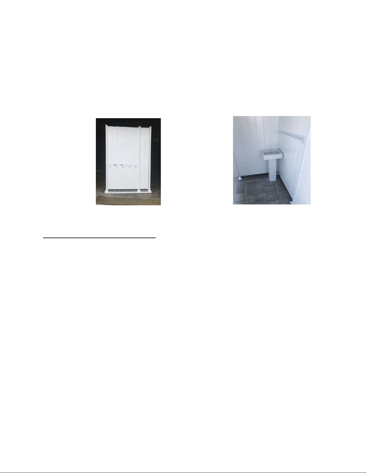
13. Sink Installation:
a. The sink comes with a hook bar that is installed to the exterior rear wall. Place the
sink into position and insure it is in position to receive sink support bolts. See pictures
below.
Caring for your AVCON Enclosure
Power Washing on a low speed (manufacturers recommended setting for vinyl to avoid
damage) in the beginning and end of the season is a great way to easily clean the unit. For more
specific areas:
Vinyl Walls:
• Most dirt can be washed off with a mild soap and water solution.
• Heavier Stains, use a non-abrasive liquid cleaner. Such as; Mr. Clean Magic Eraser, Vinegar.
• Recommended to rinse periodically with garden hose.
Decking:
• General Cleaning can be done using soap and water with a soft bristle brush.
• For heavier stains try cleaners such as; Fantastik, Lysol, vinegar and water.
Roof:
• For mildew stains use a mold & mildew cleaner to remove.
Exterior
Rear Wall
Interior
Sink Install
 Loading...