

Page 1
1
Digital Array Microphone Quick Start Guide
1 Packing List
Name
Quantity
Name
Quantity
Microphone
1
Remote Control (optional)
1
USB Cable
1
Mounting Bracket (optional)
1
Audio Cable
1
Quick Start Guide
1
Network Cable 1 -
-
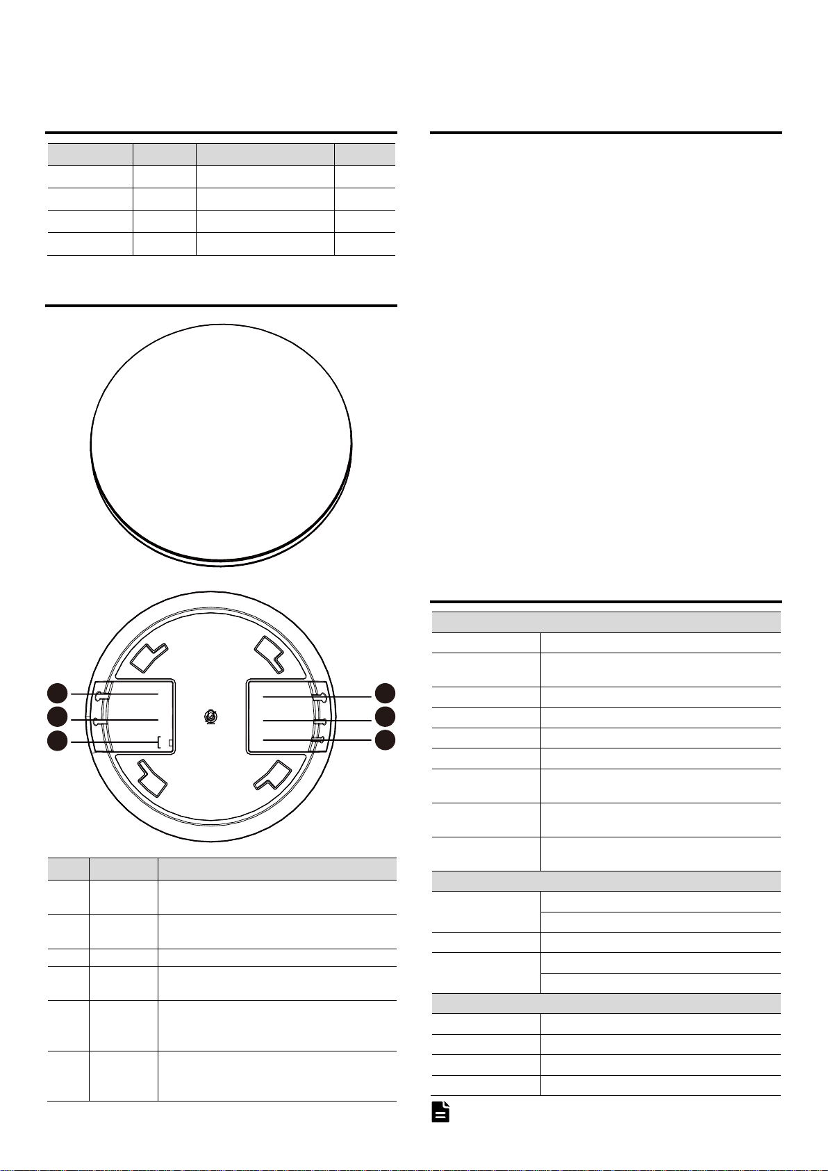
2 Appearance and Interface
No.
Interface
Description
1
Up
Up cascade network interface, cascading up
devices through PoE network cable.
2
USB
USB audio interface for connecting to the USB host
or powering the microphone.
3
M/S
Disable.
4
Down
Down cascade network interface, cascading down
devices through PoE network cable.
5
Aux2
Line audio input/output interface, sound collected
by the local microphone can be output to the
terminal or recording host.
6
Aux1
Line audio input/output interface, the audio
reference signal sent from the remote classroom
can be output to the local player.
3 Product Features
Digital Array Microphone, Long Distance Voice Pickup
High SNR ring microphone array design, clear pickup from long distance. Let the
speaker move around more freely in the room and get rid of the constraints.
Blind Beamforming, Automatic Alignment to Speaker
Blind beamforming, precise positioning, adaptive sound field environment can
achieve voice enhancement and better anti-interference ability.
Smart Audio Algorithms, Clear Natural Sound
Built-in powerful audio processing unit, ultra-low signal processing delay;
Adaptive fast convergence algorithm, voice intelligent tracking, intelligent noise
reduction, echo cancellation, automatic gain, de-reverberation and other
advanced technologies, double-talk without suppression, you can easily listen
in noisy environments. For ordinary users, there is no need for professional
tuning, and it can be used for regular conference applications when it is turned
on. For enthusiast users, you can also open the EQ interface and enter the
professional tuner mode for personalized high-end tuning.
PoE Cascade, Even Coverage of Conference Room Pickup
Flexible setting of master and slave devices, support up to 6 microphone PoE
cascade, distributed pickup and interaction, evenly covering medium and large
conference room spaces.
Standard Interface, Plug and Play
Equipped with standard USB and Aux audio interfaces, the device is plug and
play, and can meet the dual-mode application of digital and analog audio.
Hoisting/Wall/Ceiling Mounting, Simple and Flexible Deployment
Support hoisting, wall, ceiling mounting, flexible and fast deployment, and
reduce operation and maintenance costs.
4 Product Specifications
Audio Features
Microphone Type
Omnidirectional Microphone
Array Microphone
Built-in 6 mics to form ring array microphone,
360° omnidirectional pickup
Sensitivity
-38 dBFS
Signal Noise to Ratio
65 dB(A)
Frequency Response
50Hz~16kHz
Pickup Range
3m
Automatic Echo
Cancellation (AEC)
Support
Automatic Noise
Suppression (ANS)
Support
Automatic Gain
Control (AGC)
Support
Hardware Interfaces
Network Interface
1 x Up: Up cascade network interface
1 x Down: Down cascade network interface
USB Interface
1 x USB: USB audio interface
Audio Interface
1 x Aux1: 3.5mm line audio input/output interface
1 x Aux2: 3.5mm line audio input/output interface
General Specifications
Cascade Mode
PoE network interface
Power Supply
Single microphone USB/cascade PoE power supply
Dimension
Φ170mm x H 40mm
Net Weight
About 0.4Kg
Product specifications are subject to change without notice.
Up
USB
M
S
Aux1
Aux2
Down
1
2
3
4
5
6
Note
Page 2
2
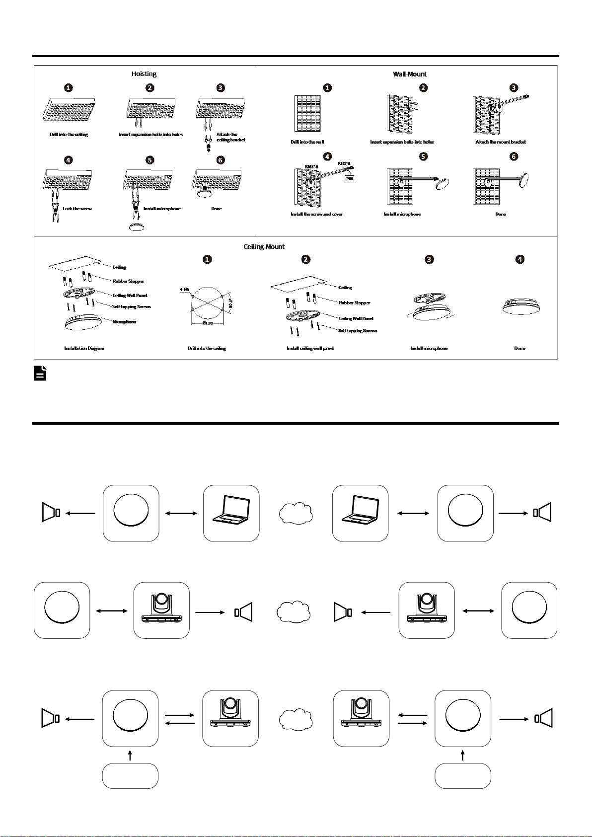
5 Product Installation
The installation diagram is for reference only. The bracket is not standard. Please refer to the actual product for the installation accessories.
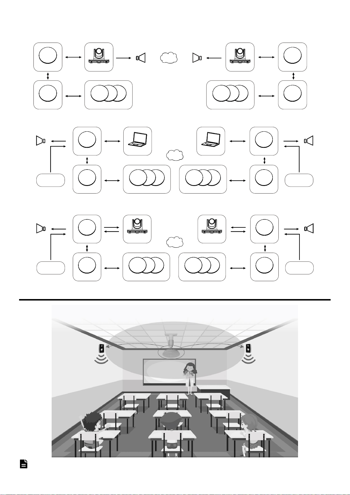
6 Network Application
6.1 Single Mode
Note
USB
Power +Audio
PCMicrophoneSPK-OUT
Aux1-Out
USB
Power +Audio
PC Microphone
Aux1-Out
SPK-OUT
USB Connection
Net
SPK-OUT
PoE
Power +Audio
TerminalMicrophone
PoE
Power +Audio
Terminal MicrophoneSPK-OUT
PoE Connection
Net
Aux2-Out
Aux2-In
Aux2-Out
Aux2-In
Microphone
USB/PoE Power
Aux1-Out
Microphone
USB/PoE Power
Aux1-Out
SPK-OUT SPK-OUT
Analog 3.5mm Connection
Interactive Terminal
Recording Host
Interactive Terminal
Recording Host
Net
Page 3
3
6.2 Cascade Mode
7 Application Scenario
The schematic diagram is for reference only. Please refer to the actual application scenario for equipment and installation.
PoE Connection
PoE
Power +Audio
Power +Audio
Power +Audio
PoE
PoE Power +AudioPoE
PoE
Power +Audio
PoE
Power +Audio
Terminal TerminalMicrophone 1
Microphone 2
Microphone 1
Microphone 2
SPK-OUT SPK-OUT
Net
Microphone 3~Microphone 6 Microphone 3~Microphone 6
USB Connection
Net
PoE Power
USB
Audio
SPK-OUT
Aux1-Out
PCMicrophone 1
Power +AudioPoE
Microphone 2
Power +Audio
PoE
Microphone 3~Microphone 6
USB
Audio
SPK-OUT
Aux1-Out
PC Microphone 1
Power +AudioPoE
PoE Power
Power +Audio
PoE
Microphone 2Microphone 3~Microphone 6
Analog 3.5mm Connection
Net
Aux2-Out
Aux2-In
SPK-OUT
Aux1-Out
Microphone 1
Power +AudioPoE
PoE Power
Power +Audio
PoE
Microphone 2
Interactive Terminal
Recording Host
Aux2-Out
Aux2-In
PoE Power
SPK-OUT
Aux1-Out
Microphone 1
Power +AudioPoE
Microphone 2
Power +Audio
PoE
Interactive Terminal
Recording Host
Microphone 3~Microphone 6 Microphone 3~Microphone 6
Note
Page 4
4
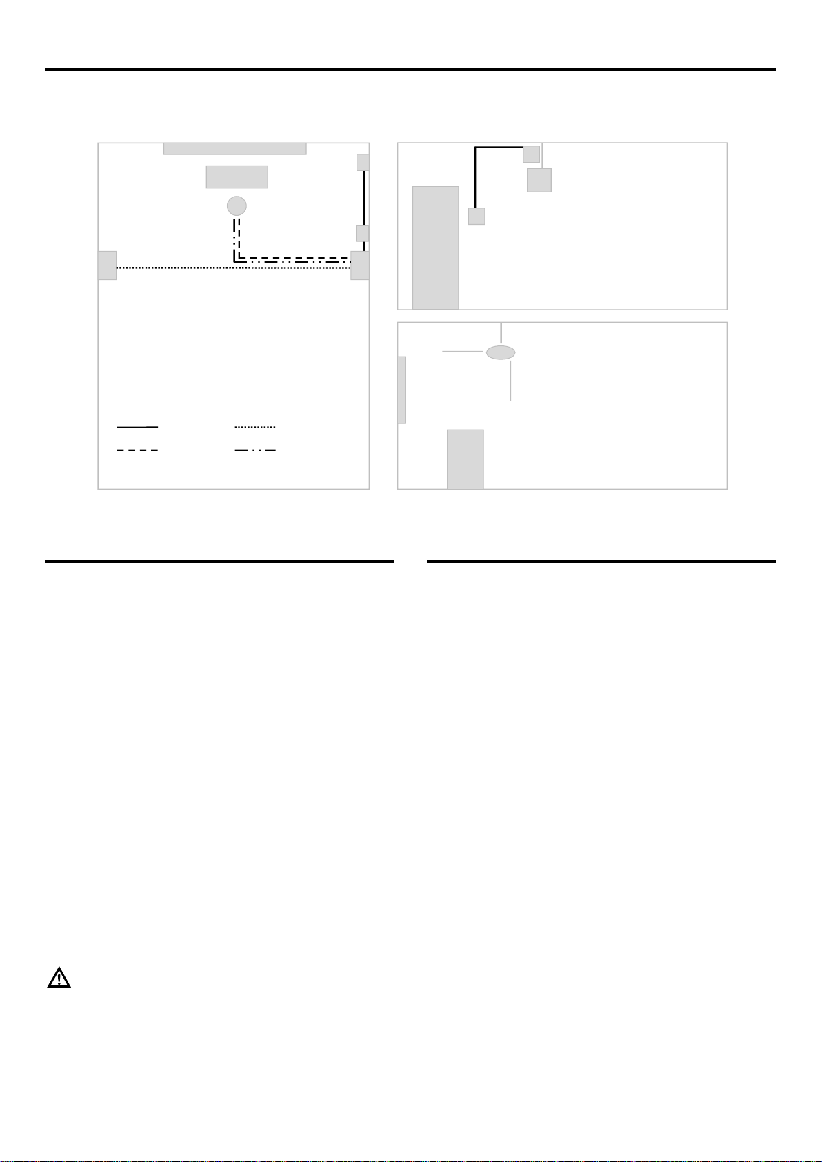
8 Scenario Installation (Classroom)
For classroom installation, please refer to the figure below. The USB interface is used as the power supply port of the microphone, and can be connected to the socket or
adapter with USB interface. The power supply voltage is DC 5V. The SPK-OUT audio output interface is output to active speakers or power amplifiers through a 3.5mm
interface audio cable. It is recommended to use low-latency active speakers first, and the speaker experience will be better.
9 Classroom Installation
9.1 Microphone Installation
1) Installation Height: In theory, the closer the microphone is to the speaker,
the better, but considering that it is too low, there may be a risk of students
accidentally reaching out and hitting the speaker, causing damage or falling.
principle, while considering security and flexible processing.
2) Installation Method and Location: It is hoisted with a boom, and the
position near the podium is centered horizontally, and the microphone disk
is facing the podium area, focusing on picking up the teacher's lecture
sound in the podium area.
9.2 Speaker Installation
1) Installation Height: The recommended height from the ground is
2.0m-2.6m.
2) Installation Method and Location: It is wall mounted with brackets. It is
recommended to install it in the middle and front of the walls on both sides
of the classroom.
9.3 Socket Installation
An optional socket panel with a USB socket can be installed next to the speaker
for easy access to the microphone and speaker. It can also be powered by a USB
adapter or directly use a device with a USB interface (TV or large display, etc.).
When the microphone and speaker are connected to the same wall plug for
power supply, the microphone and speaker need to be turned on or off at the
same time.
9.4 Switch Installation
You can choose a single switch panel, installed on the side of the door or the
blackboard, with a label, easy for teachers to open and close.
10 Problem and Solution
1) Howling appears at startup
For example, it is normal for the microphone to whistle slightly when it is
just started. When the device is just started, it needs to learn to adapt to the
live sound field environment, and it will stop automatically after the learning
is completed.
2) Persistent howling
For example, when the USB is connected to the computer, confirm whether
the listening function is turned on, and check whether the audio input and
output wiring is looped back.
3) The sound reverberation is not clear
First check whether the room is too small and the reverberation is too large,
and then check the settings of the power amplifier or speaker EQ to see if
the low frequency part is adjusted too much.
079.79.1101498_V1.0
Podium
Switch
Microphone
Socket
Speaker 1 Speaker 2
Power Cable
USB Cable
Speaker Cable
Audio Cable
Top View
Front
Door
Switch
Socket
Speaker 2
Microphone
Podium
Side View
Notice
 Loading...