

Page 1
VWC-44
0
VWC-44 Operation Manual
(Dual channel Universal/Curved Screen Edge Blender)
Technical support:
E-mail: [email protected]
Tel: 8 804 333-18-83
Skype: av-box.russia
Version: 2.04
Website: http://av-box.ru/
Page 2

VWC-44
1
Table of Contents
1 Introduction…………………………………………………………………………………………..… 4
2 Outlook and Function………………………………………………………………………………… 4
3 Features………………………………………………………………………………………….……... 5
4 Helpful Tips……………………………………………………………………………………………... 8
5 Application case study……………………………………………………………………………….. 10
5.1 Case A: Conventional curved screen edge blending………………………..…….….….. 10
5.2 Case B: Flexible display in edge blending system.................................................... . 11
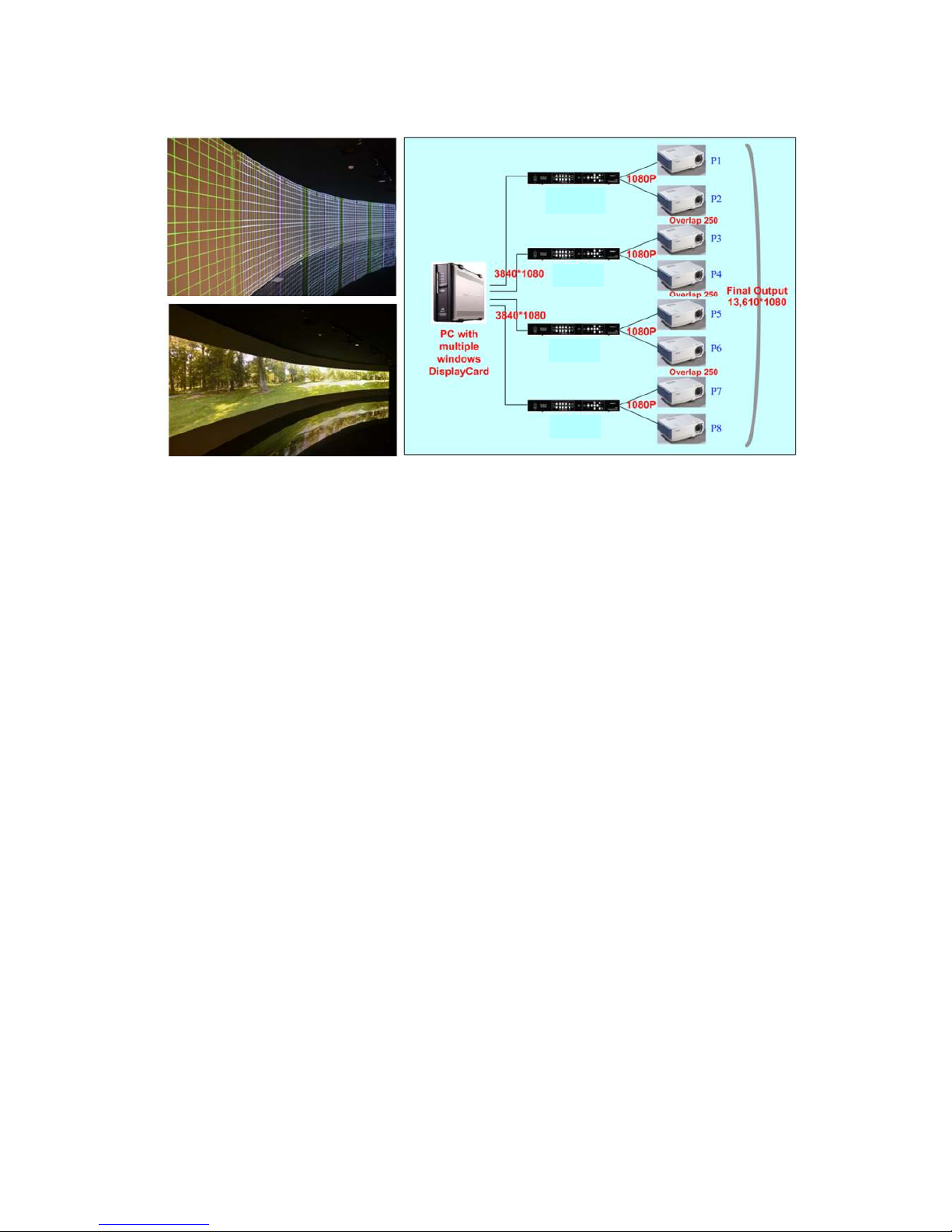
5.3 Case C: High resolution Edge Blending with multi-windows display card..........….. 12
5.4 Case D: “L/M” shape video wall with edge blending……………………………………... 13
5.5 Case E: Irregular curved display or edge blending……………………………………….. 14
5.6 Case F: Active 3D and passive 3D display………………………………………………….. 15
5.7 Case G: PIP/POP in entire screen……………………………………………………………. 16
5.8 Case H: More PIP/POP or geometry adjustment range…………………………………… 16
6 Internal Grid Pattern for Geometry Adjustment……………………………………………….….. 16
OSD menu and operation……………………………………………………………………………….. 17
7 [Picture] Color Adjustment……………………………………………………………….………..….. 17
8 [Image Setup] for PC graphics from VGA input…………………………………………………… 17
9 [Image Properties]………………………………………………………………………..…………….. 18
9.1 [Color]: Preset mode & Custom color………………………………………………………… 18
9.2 [Input Signal] selection………………………………………………………………………….. 19
9.3 [Scaling]: Display aspect ratio…………………………………………………………………. 19
9.4 [Output Mode] selection………………………………………………………………………… 19
9.5 [Orientation]: image 180〫rotation and flip………………………………………………….. 20
10 Video Wall Setting………………………………………………………………………………..……... 20
10.1 [Zoom]: split the image…………………………………………………………………………. 20
10.2 [Pan]: assign image location…………………………………………………………………… 21
10.3 [Overlap]: set image overlap pixel……………………………………………………………. 21
10.4 Example for three projector edge blending………………………………………...……….. 22
11 Passive 3D Display…………………………………………………………………….……………….. 22
11.1 System Configuration…………………………………………………………………….……. 22
11.2 System installation and setup………………………………………………………………… 23
11.3 AV-BOX 3D settings……………………………………………………………………..………
24
11.3.1 [Input Format]……………………………………………………………………………… 24
11.3.2 [Output Format]…………………………………………………………………………… 24
11.3.3 [1080p 24Hz Output]…………………………………………………………………….. 24
11.3.4 [Identity]: check final 3D settings…………………………………………………….. 25
12 Active 3D applications………………………………………………………………………………… 25
12.1 Procedures for active 3D setting…………………………………………………………….. 26
Page 3

VWC-44
2
13 [Anyplace]: Geometry Correction and Edge Blending…………………………………...…….. 27
13.1 Geometry alignment range…………..…………………………………………….…………. 27
13.2 Procedures for geometry alignment…………………………………………………….…… 27
13.3 [Reset] om geometry alignment..................................................................................... 28
13.4 Important notice for geometry alignment...................................................................... 28
13.5 [Edge Blend]………………..…………………………………………………………………….. 30
13.5.1 [Edge] selection and settings………………………………………………………….. 30
13.5.2 [Gamma]: Color correction in edge blending area…………………………………. 31
13.5.3 [Offset]: Black level uplift……………………………………………………………….. 32
13.5.4 [Corner]: Adjust [Offset] compensation position…………………………………… 33
13.5.5 [Shift]: Edge blending area shift………………………………………………………… 34
13.5.6 [Color]: Individual projector white balance and color correction………………… 34
13.6 [Gwarp] PC tool…………………………………………………………………………………….. 35
13.6.1 When [Gwarp] PC tool is necessary……………………………………………………. 35
13.6.2 System configuration……………………………………………………………………… 35
13.6.3 [Gwarp] operation…………………………………………………………………………. 36
13.6.3.1 System connection……………………………………………………………. 36
13.6.3.2 [Warp Adjust]……………………………………………………………………. 37
13.6.3.3 [Warp Shift]………………………………………………………………………. 37
13.6.3.4 [Edge Blend]…………………………………………………………………….. 37
13.6.3.5 Color [Uniformity] correction..………………………………………………. 37
13.6.3.6 [Color] adjustment……………………………………………………………… 38
13.6.3.7 [Save file] & [Save to Box]……………………….…………………………… 38
13.7 Example for 3 projector edge blending setup....…………………………………….......... 39
13.8 Edge blending with VWC-44 + 14…………………………………………………......……... 43
14 OSD Miscellaneous Functions—[Options]………………………………………………..………..... 44
14.1 System Information: [Information]…………………………………………………..……….... 44
14.2 OSD Language: [Language]……………………………………………………………………. 44
14.3 [Reset]……………………………………………………………………………………..……….. 44
14.4 [Accessibility]………………………………………………………………………………..……. 45
14.4.1 [Button Repeat Rate]………………………………………………………….………….. 45
14.4.2 [Menu Time Out]…………………………………………………………………….….…. 45
14.4.3 [Logo Time Out]……………………………………………………………………..……. 46
14.4.4 [Standby Time Out]……………………………………………………………………….. 46
14.5 [Setting]………………………….……………………………………………………..……….…. 46
14.5.1 Audio [Mute]………….…………………………………………………………….…….... 47
14.5.2 Frame Lock and Smooth Switching Mode…………………………………………… 47
14.5.3 [Box ID]…………………….…………………………………………………………..…… 48
14.5.4 [Profile Setting]………….………………………………………………………………… 48
14.5.5 [Network]………………….……………………………………………………….……….. 49
Page 4

VWC-44
3
14.5.5.1 [RS232] Command ………………………………..…………………………..… 49
14.5.5.1.1 RS232 setting…………………………………………………………… 49
14.5.5.1.2 Example of low cost RS232 controller…………………………….. 50
14.5.5.2 [Ethernet] control…………………………………………………….………….. 50
14.5.6 [EDID] setting……………………………………………………………………………… 52
15 Screen Selection…………………………………………………………………………………….….. 53
16 Projector Selection……………………………………………………………………………….……. 53
17 Specifications…………………………………………………………………………………………… 54
18 Revision history………………………………………………………………………………………… 56
Limited Warranty
This device is designed and tested to the highest standards and backed by two years’ parts and labor warranty. Warranties are
effective upon the first delivery date to the end customer and are non-transferable. Warranty related repairs include parts and
labor, but do not include repair of faults resulting from user negligence, special modifications, abuse (mechanical damage),
shipping damage, and/or other unusual damages. The customer shall pay shipping charges when the unit is returned for repair.
Manufacturer will pay shipping charges for return shipments to customers.
Manufacturer does not assume responsibility for consequential damages, expenses or loss of revenue, inconvenience or
interruption in operation experienced by the customer. Warranty service shall not automatically extend the warranty period.
FCC/CE statement
This equipment has been tested and found to comply with the limits for a Class A digital device, pursuant to part 15 of the FCC
Rules. These limits are designed to provide reasonable protection against harmful interference when the equipment is operated
in a residential / commercial environment. This equipment generates, uses, and can radiate radio frequency energy and, if not
installed and used in accordance with the instruction manual, may cause harmful interference to radio communications.
Operation of this equipment in a residential area is likely to cause harmful interference in which case the user will be required to
correct the interference at his own expense.
Page 5
VWC-44
4
1 Introduction
VWC-44 is a dual channel professional curved screen edge blending processor. It was designed for
sophisticated edge blending as well as image warping, stacking, projection mapping, irregular video wall and
passive 3D…etc.
5 inputs and 2x HDMI outputs are integrated in VWC-44. Input ports support up to 2560x1600 /
3840x1080 @60Hz and 4k UHD @30Hz resolution with 4:4:4 full color sampling. It is integrated with 10-bit
high end processor with motion adaptive de-interlace, 3:2/2:2 pull-down and supports non-VESA standard
input timing Advanced warp technology is embedded in VWC-44. User can use front panel keypads, IR controller
and PC tool to perform edge blending and sophisticated geometry alignment up to 17x17 grids. Independent
color (white balance) adjustment for each projector, overlapped area colour correction and non-overlapped
area black level uplift are also standard functions VWC-44. Users can see real time geometry and colour
adjustment and get optimized result.
HDMI loop out supports daisy chain connection up to 3840x1080
@60Hz or 4k/2k @30Hz and allows
large display with multiple VWC-44 cascaded. Video wall function in VWC-44 is to crop and allocate source
image for each projector. Complete curved edge blending can be achieved without PC, video distributor and
splitter.
If PC tool is required for sophisticated geometry alignment, user can save the final result into
VWC-44 and remote PC. During operation, no PC is required. It will provide a flexible and reliable
system. With VWC-44, users can replace high end projector with low cost projector without lens shift, warp
and edge blending. It provides easy configuration, lower system cost, reliable and flexible solution.
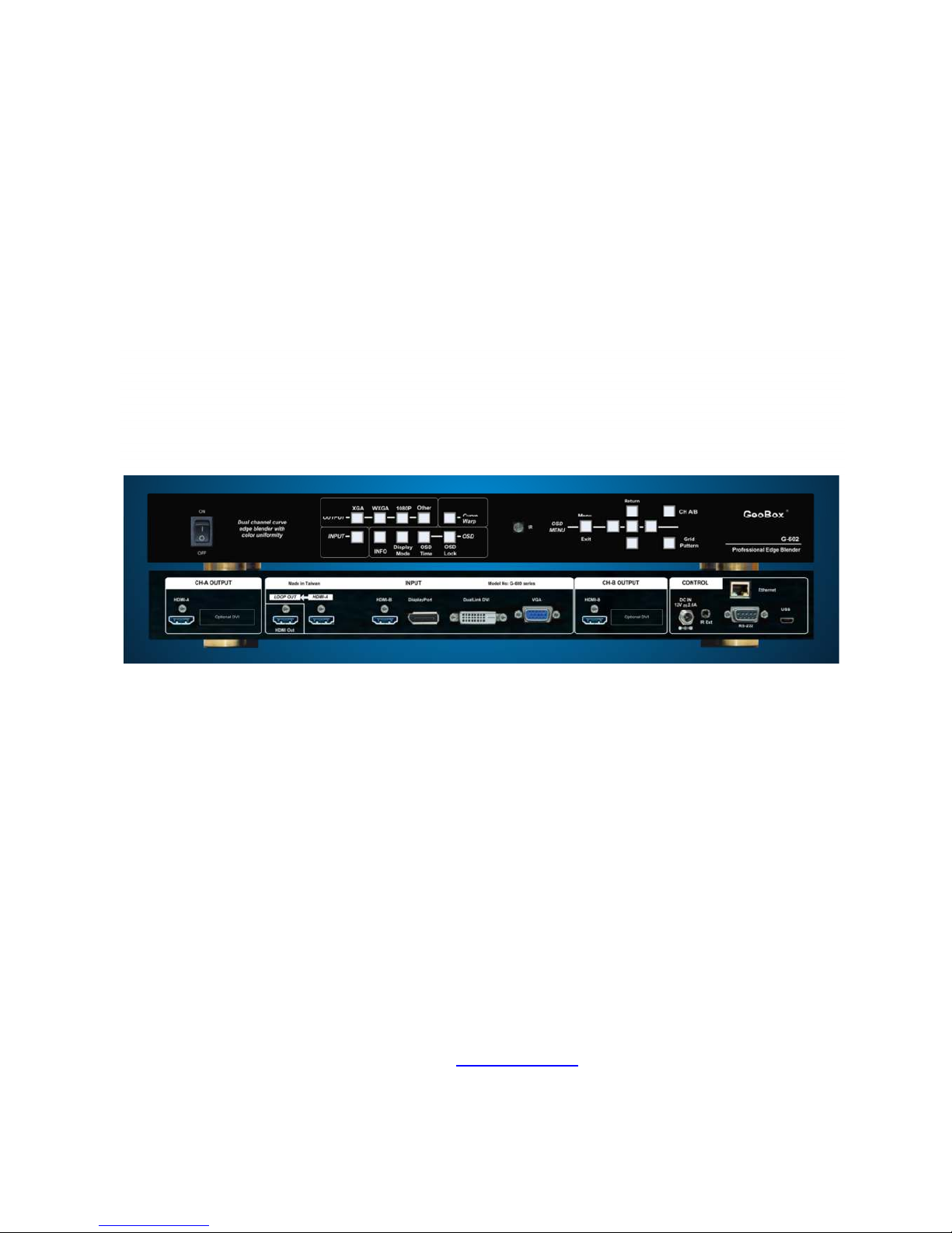
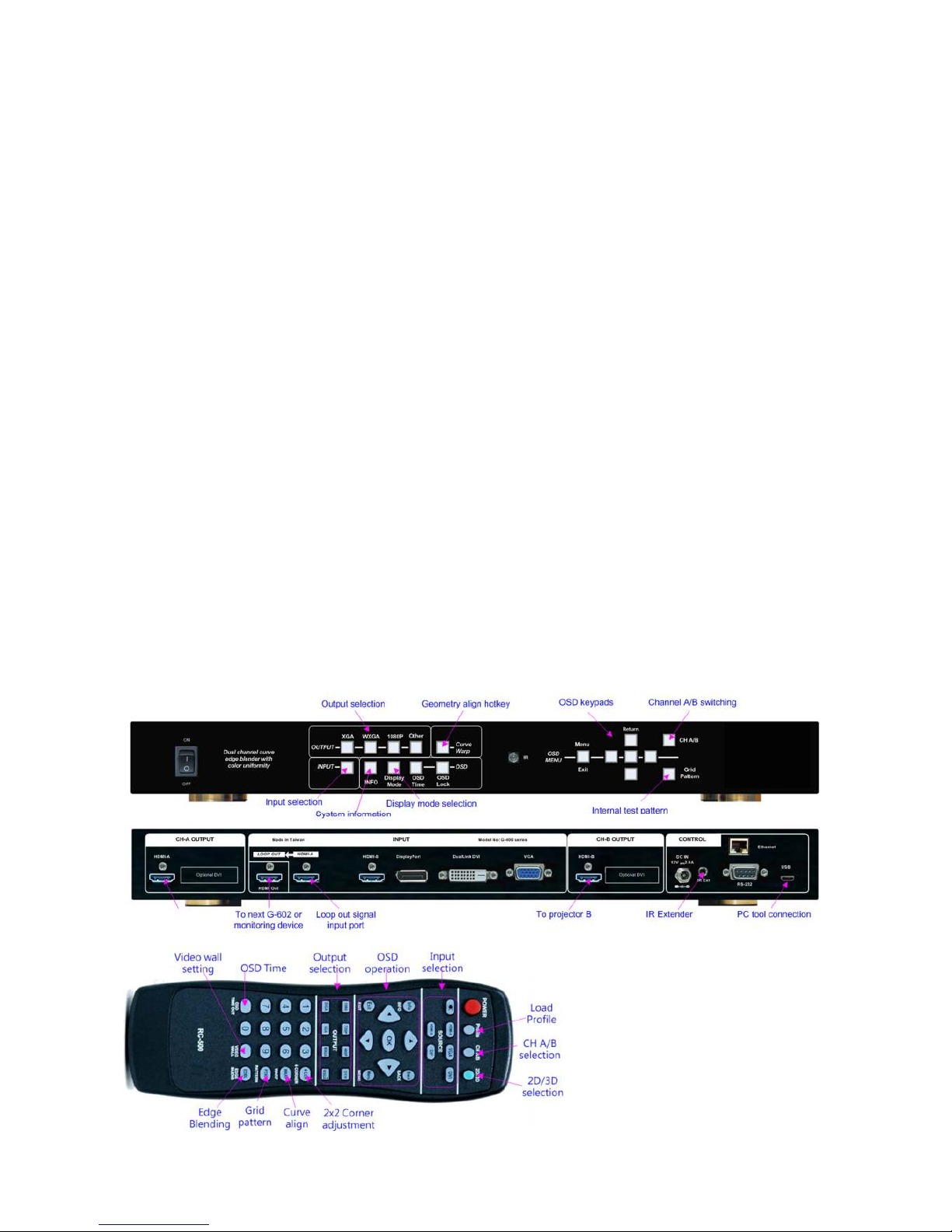
2 Outlook and Function
Page 6

VWC-44
5
3 Features:
3.1 Input and output
a. Video Input: 2x HDMI, 1x VGA (support VGA & YPbPr), 1x DisplayPort, 1x DualLink DVI
b. Video Output: 2x HDMI, support up to 1920x1200 output resolution.
c. 1x HDMI 4K/2K loop out from HDMI-A input source (raw signal without processing)
d.
1x Micro USB connector to allow user to control VWC-44 via PC tool software.
e. Frame Lock and Free Run mode to reduce projector re-sync time while input source change
f. HDMI, DisplayPort and DualLink-DVI support up to 4k/2k @30Hz, WQXGA & 3840x1080 @60Hz
4:4:4 full sampling input without compression.
g. Support none VESA standard customized input timings.
h.
Selectable EDID menu in VWC-44 for users to simplify PC or video source output timing setting.
i. Audio input: HDMI embedded audio through HDMI and DVI ports input.
j. Audio output: HDMI embedded audio through HDMI output port.
3.2 Geometry and warp
a. Advanced Gwarp technology for precise geometry alignment & edge blending.
b.
Each VWC-44 can control two projectors with different geometry adjustment and
processing settings.
c. Internal grid pattern with selectable colors for easy geometry alignment. External grid pattern can
also be used if necessary.
d. 2x2, 3x3, 5x3 grid pattern geometry alignment through manual operation without PC.
e. Up to 17x17 grid pattern geometry alignment through Gwarp PC software tool.
f. Users can see real time geometry alignment and get optimized result.
g. Precise image cropping, resizing, positioning and aspect ratio adjustment.
h. Free Gwarp PC tool is available for sophisticated geometry alignment through USB connection.
3.3 Edge Blending
a. Edge blending in all edges up to 900 pixels overlapped area, no projector number limitation.
b. Precise gamma correction in overlapped region to eliminate banding effect.
c. Precise black level uplift to eliminate grey banding effect in edge blending area due to optical light
leakage from the projector.
d. Color correction in black level between edge blending area and none edge blending area is
available for color balance in black level.
e. Independent RGB gain and offset adjustment for white balance & color correction in each
projector.
f. Support 360 degrees curved screen, wave screen or irregular curve screen edge blending.
3.4 Passive 3D and active 3D applications
a. Decoding 3D formats from Blue Ray, Set Top Box, PC…for dual projector passive 3D display.
b. Convert active 3D signal up to 1080p @120Hz for FHD passive 3D display.
Page 7

VWC-44
6
c. Support HDMI 1.4a 3D formats, including 1080p/24Hz frame packed, Side by Side, Top-Bottom,
Line interleave and frame sequential for passive 3D display.
d. Support 3840x1080 side by side and 1080i/60Hz frame packed 3D from Sony FHD camcorder.
e. Support PIP function in passive 3D display, both main and PIP windows are still with 3D effect.
f. Special algorithm for perfect synchronization in RH/LH channels to get the most comfortable
passive 3D display.
g. Support passive 3D image geometry alignment, curved screen display, image stacking and edge
blending.
h. Convert 1080p/24Hz frame packed 3D from Blue Ray or 1080p/120Hz active 3D signal from PC or
Nvidia 3D Vision card into 720p/XGA 120Hz signal for active 3D display.
i. Support active 3D image warp (for curved screen display), image stacking (enhance brightness)
and edge blending (enlarge display screen).
3.5 High end video processing
a. 10-bit 4:4:4 full sampling processing with 3D motion adaptive de-interlace, low angle algorithm and
3:2/2:2 movie mode detecting and recovery.
b. With Picture-in-Picture function (PIP) at any location of the image up to XGA resolution.
c. Intelligent color adjustment, including preset display modes, hue, saturation, brightness, contrast
sharpness adjustments and RGB separate adjustment for color fine tune.
3.6 Video wall function
a. Video wall function to split, crop and magnify the image with pixel based overlap region and bezel
adjustment. No additional image splitter is required for edge blending.
b. Video wall control & edge blending up to 15x15 matrix displays from single image source, no
display number limitation with multi-windows display card.
c. Image flip and rotation function can be applied to video wall to provide irregular video wall display.
3.7 Image flip and rotation
Built-in image 180 degrees flip down function. This function is convenient for rear projection and
system installation.
3.8 Gwarp PC tool
a. One PC Gwarp tool can control two projectors.
b. Geometry alignment up to 17x17 grids. Good for irregular or sophisticated curved alignment.
c. Embedded with edge blending and color uniformity correction.
d.
Adjustment result can be saved in AV-BOX. After finishing adjustment, no more PC is required.
3.9 Features for system integrator
a. 1U size with optional ear mounting rack.
b. Reliable and durable design for long term industrial and commercial applications.
c. Able to use low cost projector, no lens shift, warping or edge blend function are required
Page 8

VWC-44
7
d. Full functional keypads & IR control.
e. Optional Ethernet control.
f. With internal grid pattern for quick and easy setup.
g.
ID # for each AV-BOX. Convenient for system installation and control through IR, RS232
and Ethernet.
h.
Gwarp PC tool is available to control VWC-44 through micro USB connection.
i. Keypad Lock (press menu for 5 seconds) to avoid setting loss due to negligence.
j. Up to 5 profile settings for flexible display modes memory and recall.
k. Power saving control through input source detecting.
l. Integrated with IR extender (up to 20 meters), RS-232 and optional Ethernet control.
m.
By connecting with WiFi Router through Ethernet ports, user can control VWC-44 through
devices integrated with WiFi such as iPad, smart phone or Notebook PC.
n. Friendly user interface, low entry level, no PC is required, more reliable. Lower the cost for
installation and after service.
o. Weight and dimensions: 440*189*45mm, 2.4kg (body only)
Page 9

VWC-44
8
4 Helpful Tips for system installation and setup
a. Select digital input to get better image and avoid image position shift.
b. If 4k signal connection distance is more than 10m, please select a certified HDMI cable to avoid
unstable signal connection.
c. The quality for signal adapter or converter, such as HDMI to DVI adapter and DisplayPort to HDMI
co
nverter, may downgrade the signal quality and cause issue. Please select qualified ones.
d.
If user can see blue background image with [Power Saving Mode] message, it means the signal
connection between projector and AV-BOX is OK but no input signal detected by AV-BOX.
Please check signal source or replace a different input source to test.
e.
If user can’t see [Power Saving Mode] message or splash screen, please check the connection
between AV-BOX and projector. User can connect to a monitor to check the output from AV-BOX.
f. The output resolution setting shall be the same as projector native resolution to get the best video
quality. After geometry alignment, this output resolution can’t be changed. Otherwise, geometry
position will shift and required further adjustment.
g. In the application with short through ratio projector on curved screen, it is possible that the image
location is beyond the maximum adjustment range in manual adjustment. In this case, Gwarp PC
tool may be required to double the adjustment range.
h. During installation setup process, please apply FHD signal to the system for easy setup. After
finish the setup, user can select optimized EDID from OSD menu to get optimized video quality.
i.
The optimized EDID should be the final resolution after edge blending. For instance, if user uses
three XGA projectors for edge blending with 250 overlapped pixels, then the best signal for this
setup will be 1024*3-250*2=2572. It means 2572*768 will be the best signal resolution for this
setup. User can select one EDID near this timing as default EDID in AV-BOX. If no suitable
EDID can be selected, user can create customized output mode in PC. AV-BOX can support
none-VESA standard input timings.
j. In addition to the resolution settings, user needs to provide a content with the same aspect ratio
as screen to ensure no distortion on the screen.
k. To reset all projectors before edge blending to get the same settings in all projectors.
l. To turn off auto keystone function to avoid image shift.
m.
In order to avoid interference among multiple AV-BOX during the installation, user can set ID
number for each AV-BOX through [Options] Menu. Press number keys in Remote Controller
for the control of multiple AV-BOX:
850: simultaneous control for all AV-BOX
851: control AV-BOX ID No. 1
853: control AV-BOX ID No. 3
n. OSD Lock / Unlock: When continuously press [OKD Lock] key on Front Panel or [Menu] key in IR
Remote Control for 5 seconds, the OSD function will be locked to prevent from setting change by
negligence. To press [OSD Lock] key or [MENU] key for 5 seconds again, it will unlock OSD and
user can manipulate the OSD again.
o. [Image Setup] menu will not be activated if the input source is not from VGA.
Page 10

VWC-44
9
p.
Please reset AV-BOX before any new application to avoid unexpected settings in the system. If
deeper reset is required, user can turn on AV-BOX and press both [Menu] + [Pattern] key on
front panel and power on AV-BOX again for 5 seconds. It will reset the system
q. To set [Menu Time Out] to “0”, the OSD will appear till the OSD Menu has been turned off
manually.
r. Default Internal Grid Pattern represents 32x32 pixels no matter which input resolution is selected.
s.
Only VWC-44 HDMI-A input port can provide HDMI raw signal loop out for daisy chain
connection. This loop out signal is without any processing.
t.
When [Gwarp] PC tool is used, user needs to save the setting into VWC-44 through the OSD
menu:[Anyplace] [Gwarp Pro] select [UserMap 1-10] to save the settings. Then PC can be
removed.
u.
When Power Off/ON VWC-44, it will maintain the final settings status but it is possible to be
changed by others.
v. User needs to save the final setting into [Profile] under [Options] menu for long tern stored inside
the system. Even the system is reset, the [Profile] settings will be kept without change.
w. Continuously press PATTERN button, internal test pattern will show different colors for easy
installation:
White—Red—Green—Blue—Blank. When in “Blank”, user can use external pattern and see
OSD.
x. Please use INFO hot key on front panel or remote controller to check the input and output timing.
y. Below hotkeys are available in remote controller:
[OSD Time Out], [Warp] geometry alignment, [Video wall], [Edge Blend], [Info], [CH A/B] switching.
Page 11
VWC-44
10
5 Applications case study
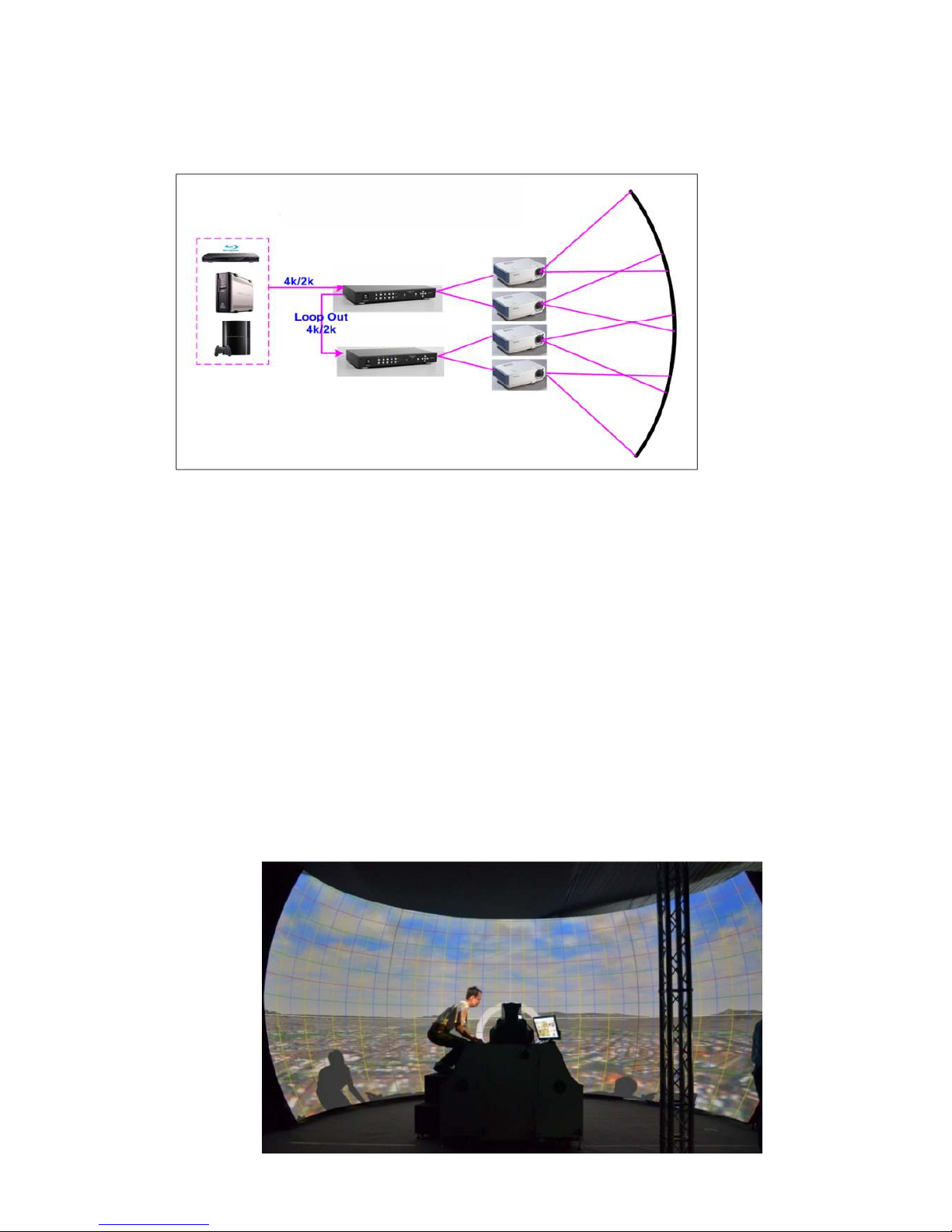
5.1 Case A: Conventional curved screen edge blending
a. No PC is required.
b.
To feed signal from any signal source to VWC-44 HDMI input port and connect to the 2nd VWC-44
through loop out port. No HDMI splitter is required. The latency among these VWC-44 will be only
few lines. The max daisy chain connection can be up to about 12x VWC-44 . However, it will
depend on the HDMI cable length and quality. User needs to check in advance.
c. The maximum input resolution can be up to 2560x1600/3840x1080 @60Hz or 3840x2160 @30Hz to
get the best result in multiple projector edge blending.
d. User needs to do geometry adjustment and warping function to align the images onto curved screen
and let the images between two projectors have the same grid size and with necessary overlap pixels.
e.
After geometry and warp adjustment, user can apply Video Wall function in VWC-44 to split the
image, cropping the correct area and assign to each projector.
f. The last step is to do edge blending to combine the images into one seamless big screen.
g. If the application is in dark environment, to do [Offset] compensation is required to eliminate black
level color difference between edge blending area and none edge blending area.
4K/2K edge blending with VWC-44
Page 12
VWC-44
11
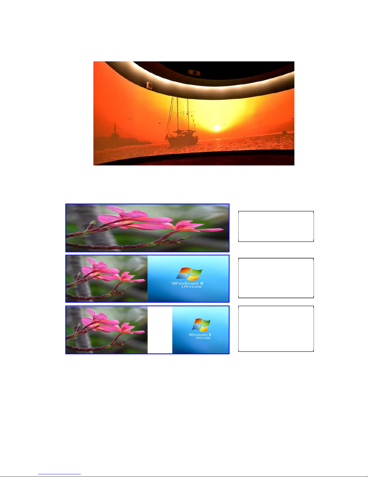
(Flight simulation system with 3 projectors on half Dome)
(Cylindrical curved screen edge blending up to 360 degrees with 6x projectors and 3x VWC-44)
5.2 Case B: Flexible display in edge blending system
1. 4 projector edge blending can be configured as below:
2. 4 projectors edge blending into one content
3. Independent two discrete contents (2+2)
4. Two projectors edge blending and one single projector display with original aspect ratio.
5.
If user can add one 101 at the front end, user can implement PIP/POP across entire display
screen.
6. User can save the setting into Profile and recall at any time.
7.
If discrete 4 projector displays is required, single channel AV-BOX (104) is required.
2 projectors as one edge
blending system to
provide 2+2 displays
2 projectors edge blending
+ one projector display
independent image in
original aspect ratio
4 projector edge blending
Page 13
VWC-44
12
5.2 Case C: High resolution Edge Blending with multi-windows display card
a. Usually, each full HD signal can feed up to 3- 4x projectors for 10m screen and still keep acceptable
v
i
deo quality (it will also depend on the watching distance).
b.
Many video cards can easily provide upto 4x 3840x1080 outputs for VWC-44
c.
Each PC output is fed into one VWC-44, then to two projectors. 4 outputs will be fed to 8 projectors.
d. If the overlap pixels is 250, then it can provide a video wall with 13,610x1080 output resolutions.
e. If the watching distance is 5m, the video pixel pitch can be about 5mm. In this case, the total screen
size can be up to 13610x5mm=68m and still keep acceptable video quality.
f.
The display card should have the function to set overlapped pixels between two output ports. In the
case of four output display card, PC should be able to set overlapped pixels between output P2/P3,
P4/P5 and P6/P7. The overlapped pixels should be up to about 20%-25% of the output resolution.
The rest overlap areas (P1/P2, P3/P4, P5/P6, P7/P8) can be set by AV-BOX.
g. If the display card doesn’t have above mentioned overlap setting function, then user needs to create a
content with some overlapped pixels up to about 20%-25% between outputs.
h.
AV-BOX can do geometry alignment, split the image, assign image for each projector and capture
the right size of the image for edge blending.
i.
If one output can be connected to two VWC-44 through daisy chain connection, one 3840x1080
output can be connected to 4 projectors and total projectors will become 16. If one PC output can
be daisy chain connection to 3x VWC-44, then 4 output will connect up to 24 projectors and the total
video wall can be more than 50m and still with good video quality.
j. The advantage for this kind of application is high output resolution. However, it still has some
limitations.
The major input source shall come from PC but not from multiple input sources
The PC shall have enough processing power to handle multiple output windows. More video
output ports from display card will occupy more PC resource.
Different playing contents may also require different CPU resource. User needs to test before
Page 14
VWC-44
13
implement this kind of display system.
The output aspect ratio will be changed depending on the display system. User needs to take
care of the aspect ratio in the source content in advance.
k. Edge blending will increase the total resolution. Usually, the video quality will be good enough for most
of the applications if output resolution in each projector can reach XGA resolution.
l.
User can connect with other signal sources like Blue Ray or Media Player to other input ports in VWC-44. By
selecting different input ports and applying different AV-BOX settings, it will provide different display modes. For
example, for 3 projector edge blending, user can set all three edge blending, two projector edge blending and one
has discrete display or each projector has independent content.
m.
AV-BOX can reduce the CPU loading in PC and reserve more CPU resource to handle interactive
or other operation without image lag.
5.3 Case D: “L/M” shape video wall with edge blending
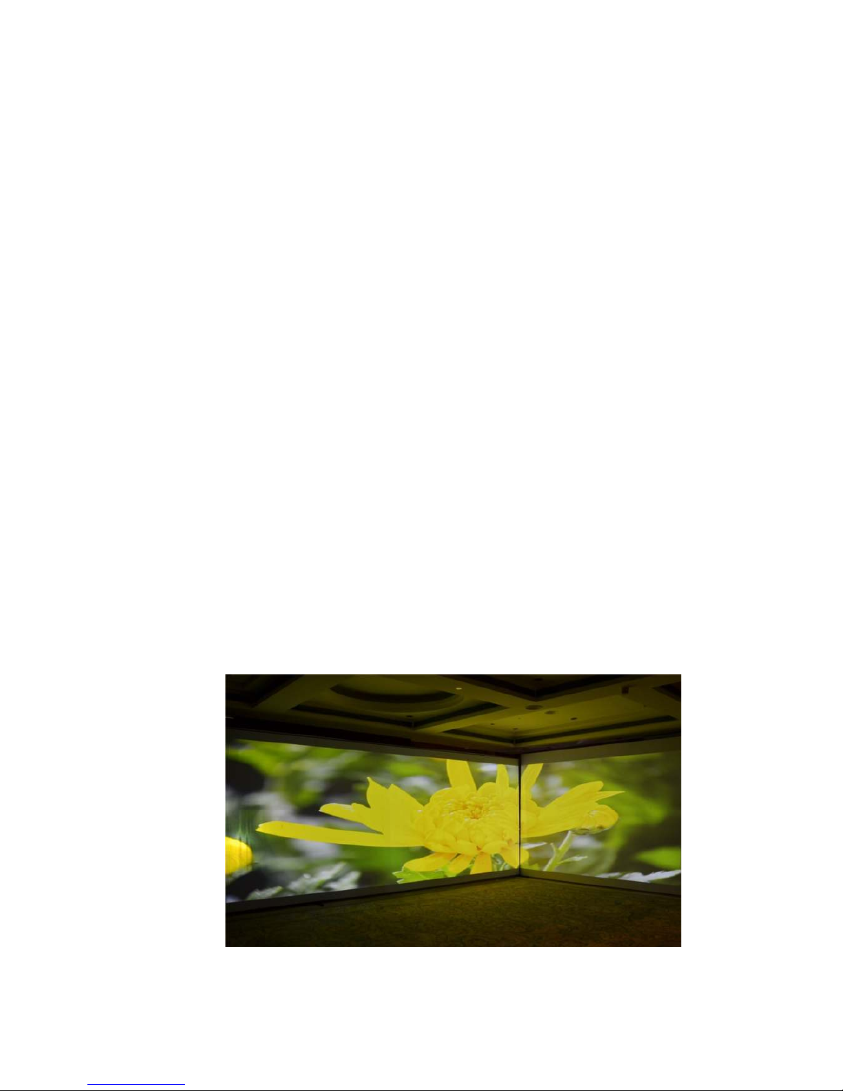
Below is example of the application in restaurant with “L” shape video wall:
a. 3x WXGA projectors: two projectors edge blending on the front screen and another projector is located
at side wall.
b. The image is met at the corner. It is not necessary to do edge blending at the corner. User just needs to
do geometry alignment to let the image meet at the corner.
c. User can use Video Wall function to split the image into 3x (using ZOOM function) and use PAN and
OVERLAP function to capture the right size of the image and assign to each projector.
d. Three projectors should have the same image captured size to avoid different scaling factor in the
projectors. It can be adjusted through Video Wall Overlap function.
e.
To do edge blending on the front two projectors and the image in side wall only needs geometry
alignment and Video Wall setting. User can use any model of AV-BOX that has video wall
function inside.
Page 15
VWC-44
14
5.4 Case E: Irregular curved display or edge blending
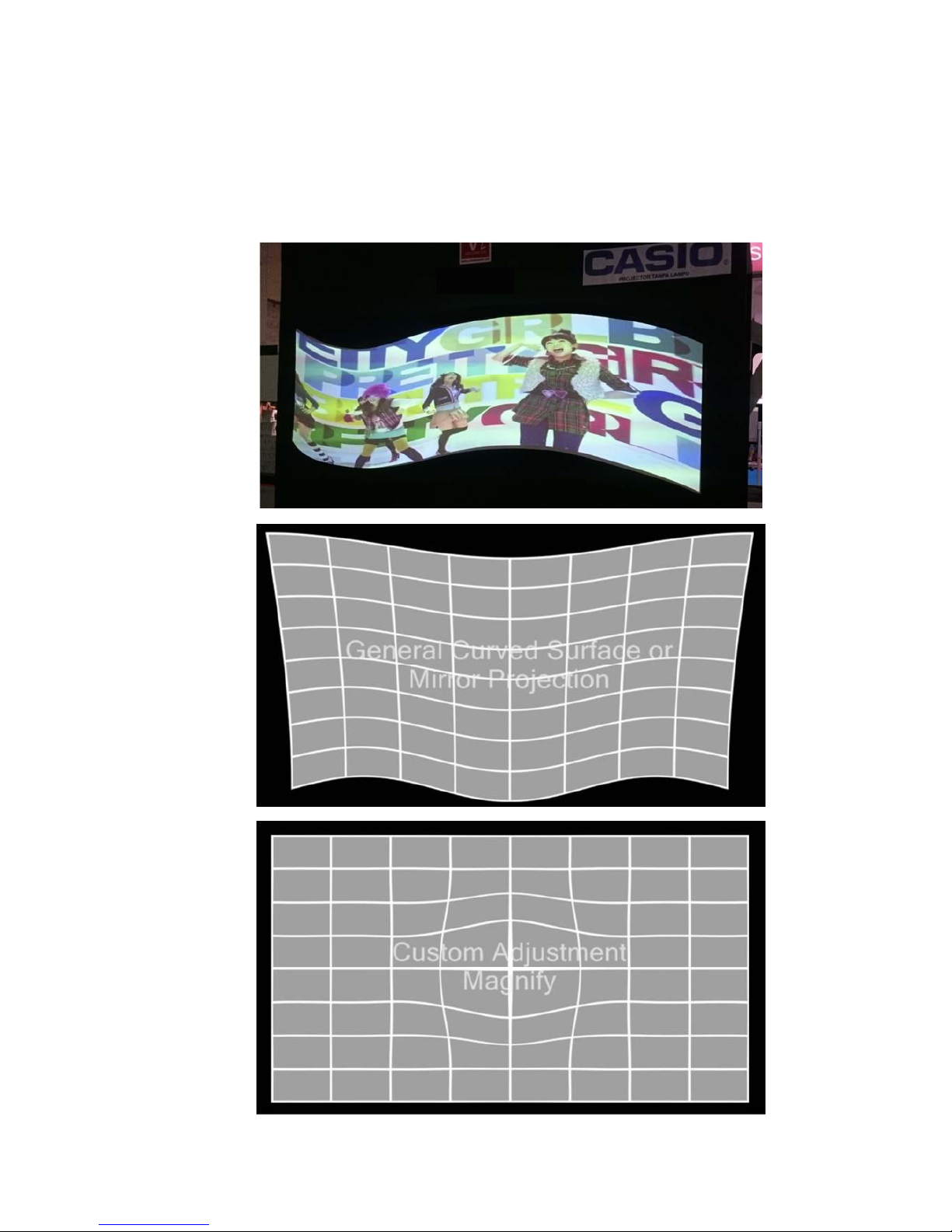
User can use VWC-44 to do manual adjust and achieve curved display for most of regular curved
screen. Once the screen has irregular curve or special shape, then to use Gwarp PC tool for the
alignment may be necessary. After geometry alignment, user can execute Video Wall and Edge Blend
function in AV-BOX to complete an irregular curved image display with multiple projectors.
Page 16
VWC-44
15
5.5 Case F: Active 3D and passive 3D display
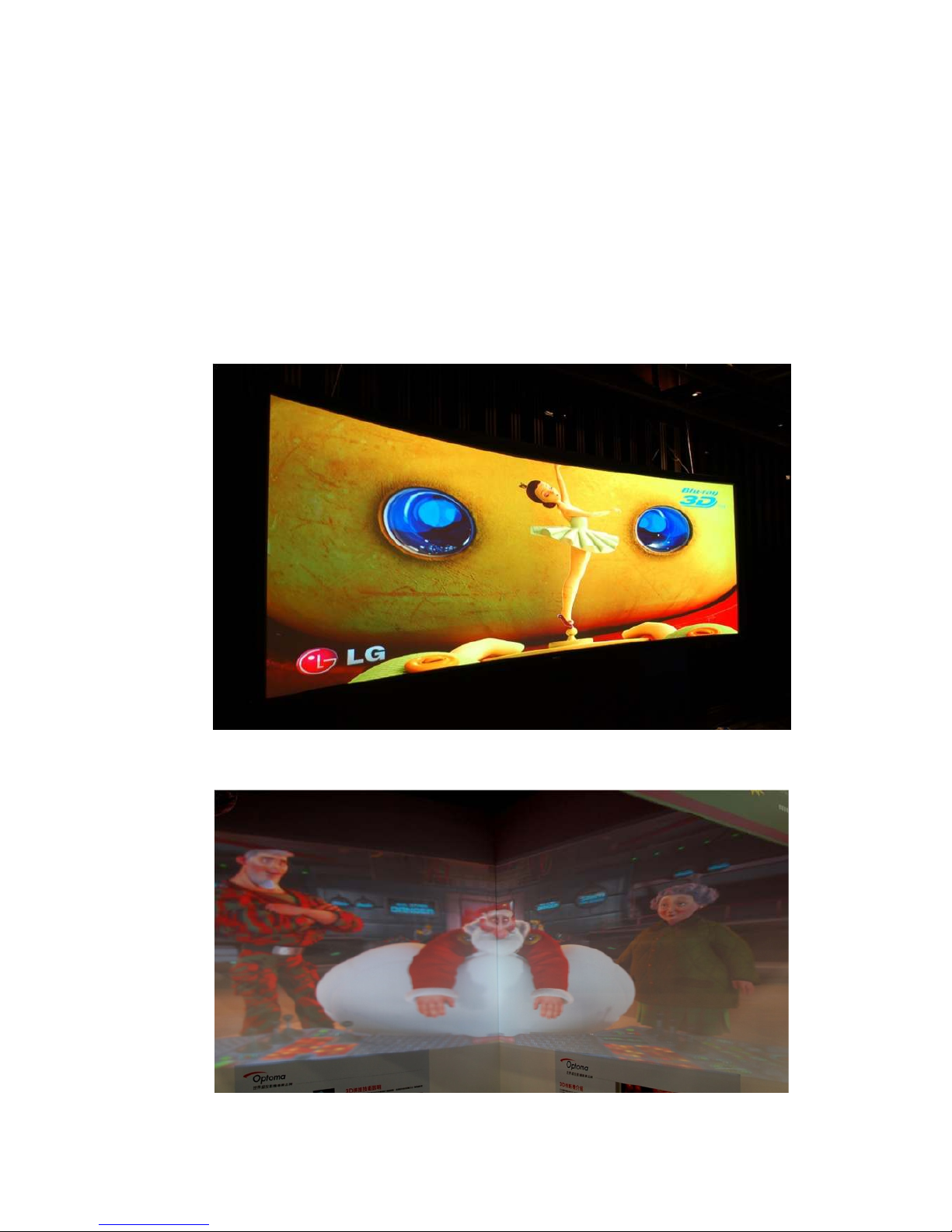
User can use one VWC-44 as 3D de-multiplexer to decode HDMI 1.4 3D signal or active 3D frame
sequential 100/120Hz signals for passive 3D display using two projectors. This kind of passive 3D
application can be expanded to bigger screen through edge blending with more AV-BOX and projectors.
User can also increase brightness in 3D system through image stacking with more projectors.
User can convert Nvidia 3D Vision 1080p 120Hz 3D signal and 1080p/24Hz frame packing 3D from Blue
Ray into 720p/XGA 100Hz/120Hz frame sequential 3D signal for DLPLink 3D Ready projectors. Besides
3D format conversion, AV-BOX can also apply geometry alignment for active 3D curved screen display.
Through VWC-44, user can do edge blending or mage stacking with multiple projectors to get big active
3D display with brighter image.
(4x Epson full HD projectors to do edge blending on curved screen for passive 3D display)
(2x Optoma XGA projectors on “L” shape video wall with active 3D display)
Page 17
VWC-44
16
5.6 Case G: PIP/POP in entire screen
User can add one 101 at the front end of the system and enable PIP/POP function, then feed the output
to VWC-44 for edge blending or other applications. Then user can have flexible PIP/POP with flexible
size, location and aspect ratio in the whole screen.
5.7 Case H: More PIP/POP or geometry adjustment range
If double PIP windows, double geometry adjustment range or special effect is required, use
can connect more AV-BOX in serial to get more flexible applications.
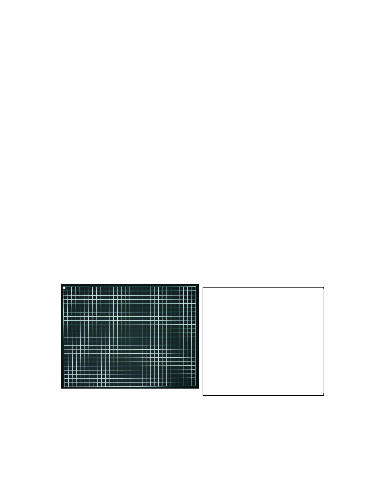
6 Internal Grid Pattern for Geometry Adjustment
To press [PATTERN] key in Remote Controller or at front panel, it will show internal grid pattern. By
continuously pressing [PATTERN] key, different color grid patterns will appear cyclically from White Red
Green Blue Blank. If user wants to disable grid pattern, please use Exit key in Remote Control or
Menu key in Front Panel. Each grid pattern is 32 pixels in width and height. User can calculate the overlap
pixel via the number of grid pattern and figure out the pixel number.
This internal pattern can’t co-exist with OSD menu. During geometry adjustment, user needs to select
adjusting item, then click [Enter] to pop-up grid pattern. If user wants to use external grid pattern from PC
or other signal sources or see OSD menu instead of internal grid pattern, user can continuously click
pattern key to show it. A flashing indicator at the adjusting point will appear. User can see real time grid
pattern change during the adjustment. It is recommended to connect through digital interface (HDMI or DVI)
to the projector to avoid any position shift after installation.
If user wants to show the adjustment value (pixel #) while doing geometry alignment, user can
continuously press [Pattern] key to show the adjusting value.
Note: The grid size of VWC-44 is 32x23 pixels and other model is 50x50 pixels. If user wants to do edge
blending with VWC-44 and other model, user needs to apply external grid pattern so that all AV-BOX will
show the same grid pattern. Please download [Edge Blending grid pattern] from AV-BOX website.
Continuously press [Pattern] hotkey, user will show the same external pattern in all projectors for easy
geometry alignment. If user uses Gwarp PC tool, user can set grid size to 50x50 to get the same grid
size in all projectors.
I
nternal grid pattern can be displayed
after press [PATTERN] key. External
pattern can also be applied. When use
Gwarp PC tool for geometry alignment,
user can change grid size.
Please press CH A/B to switch to second
channel and press [Pattern] key to show
second channel grid. Continuously press
[Pattern] key will change grid color.
Press [Exit] to exit from grid pattern.
Page 18
VWC-44
17
OSD menu and operation
7 [Picture]--Color Adjustment
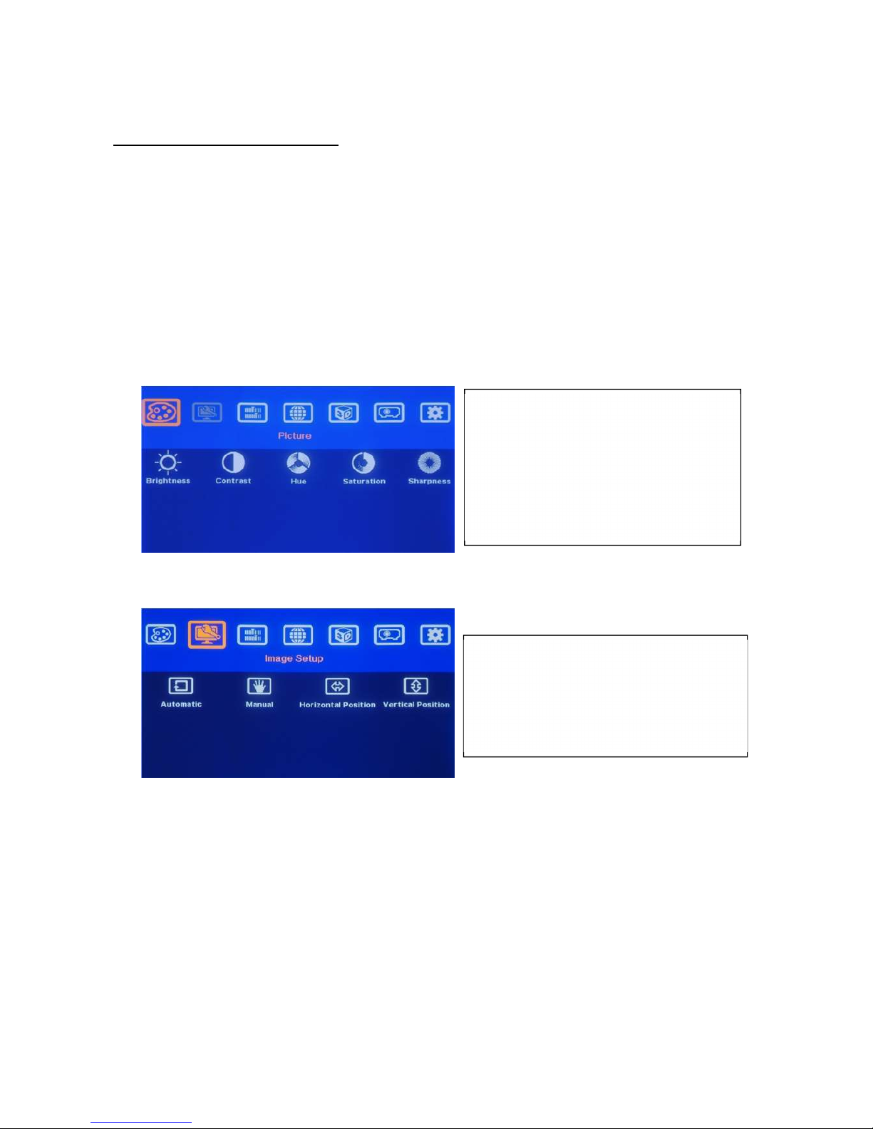
a. The items under [Picture] menu will apply to both processing channels.
b
. This menu is only active under below conditions:
[Picture] menu will be grayed out and not functional when the color setting is in [Preset Mode]
under [Image Properties] menu. User needs to get into [Custom] menu and press [Save] menu to
activate [Picture] menu.
When the input signal is in YUV domain, all the items under menu are free to be accessed.
If the input signal is in RGB domain, only [Brightness] and [Contrast] can be adjusted.
c. User can do further separate RGB individual color adjustment under [Image Properties] menu.
8 [
Image Setup] for PC graphics from VGA input
a. [Automatic]: It will do automatic image position alignment.
b
. [Manual]: manual setting for signal Phase and Clock to eliminate image noise in analog input
c. [Horizontal Position]: to adjust the image horizontal position.
d. [Vertical Position]: to adjust the image vertical position.
e.
When the input is VGA signal, AV-BOX will execute image position auto alignment. After this
process, AV-BOX will not do auto alignment again to avoid image shift unless VGA input is from
another PC.
F
ive items under [Picture] menu. All the
adjustments will be applied to both
processing channels.
Under [Edge Blend] menu, user can
adjust color in individual projector.
[Image Setup] menu can only be activated
w
hen video signal input is from VGA analog
input port.
Page 19
VWC-44
18
9 [Image Properties]
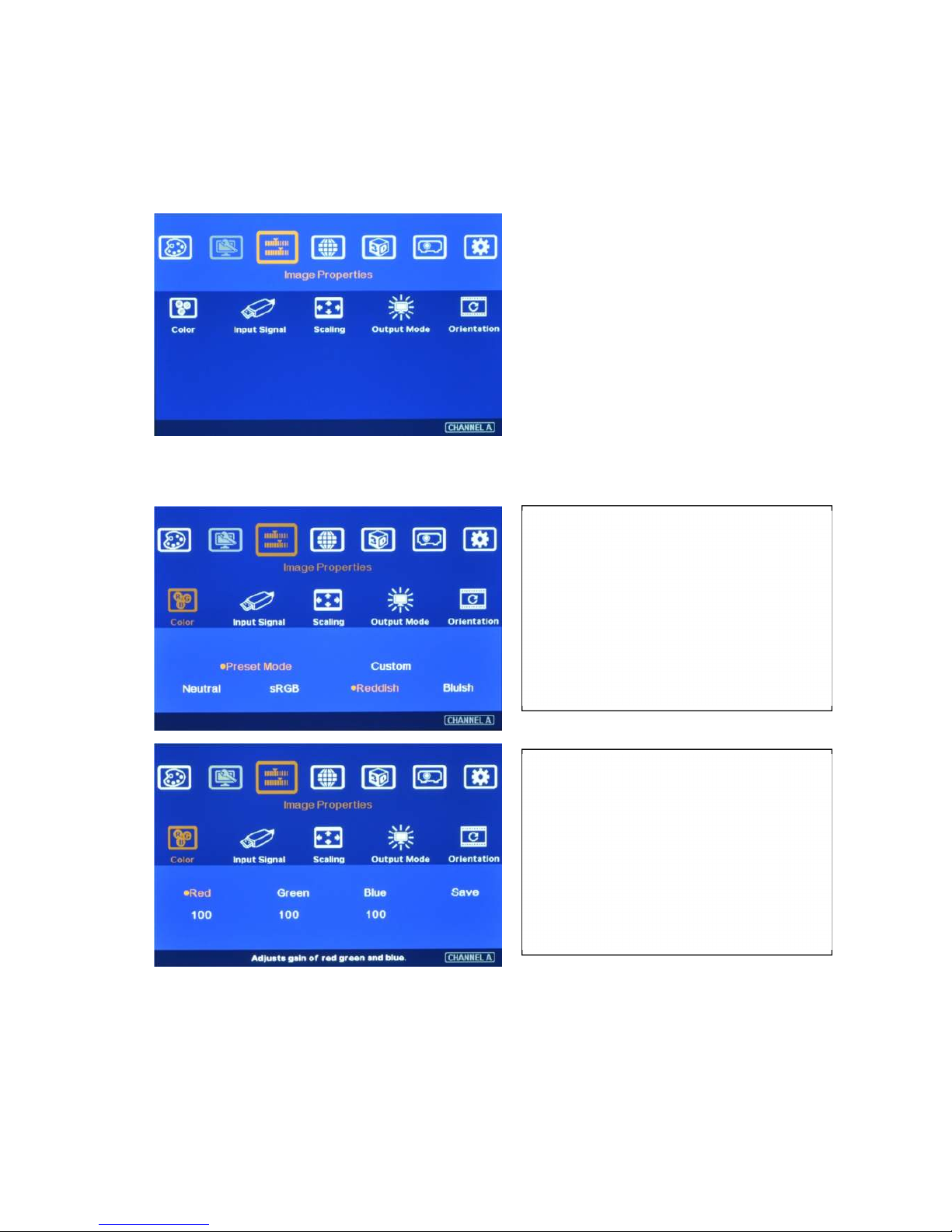
[Image properties] is designed for the selection of image color (Preset and discrete RGB), input port, aspect
ratio, output mode selection and image flip setting. The functions under this menu will apply to both
processing channels.
9.1 [Color]: Preset Mode & Custom color
Two items under [Color] menu
Four items under [Preset Mode]
Preset color is [Neutral]
This setting will apply to both processing
channels.
Discrete RGB color adjustment under
[Custom] menu
When user presses [Save] menu, then all
items under [Picture] can be accessed for
further adjustment.
This setting will apply to both processing
channels.
Page 20
VWC-44
19
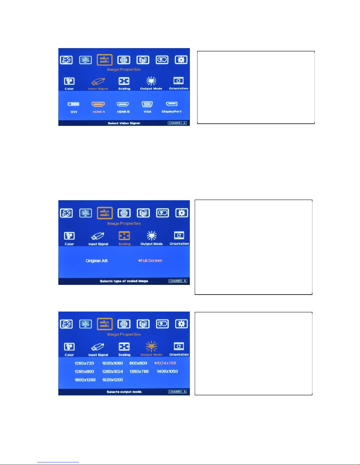
9.2 [Input Signal] selection
DVI input port can be DVI-D, VGA and HDMI (HDMI to DVI adapter is required) input signals.
When input HDMI signal into DVI port, it can support up to 4k/2k @30Hz with embedded audio.
The input signal from HDMI A port can be looped out for daisy chain connection. All the other input
signals can’t be looped out.
YPbPr video signal can be connected through VGA input port but YPbPr to VGA adapter is required.
9.3 [Scaling]: Display aspect ratio
9.4 [Output mode] selection
Output resolution shall be the same as projector native resolution to get the best video quality. Please set
the right output resolution before execute geometry alignment. Change output resolution will also change
the geometry alignment result.
User can press [Input] hotkey on front
panel to change input port. Message will
be showed on the screen.
User can select input port directly from IR
remote controller. Keypads on front
panel.
[Original AR]: To display with input source
aspect ratio
[Full Screen]: To extend the image to full
screen.
When implement edge blending or video
wall, please select [Full Screen].
Otherwise, it may show wrong result.
Please also set the right aspect ratio
setting in the projectors.
10 preset output modes.
Special output mode can be customized.
When the input is 50Hz refresh rate, the
output will be also 50Hz to maintain high
quality image.
When the input is 120Hz for active 3D,
the output will keep 120Hz but the output
resolution is limited to XGA & 720P only.
Page 21
VWC-44
20
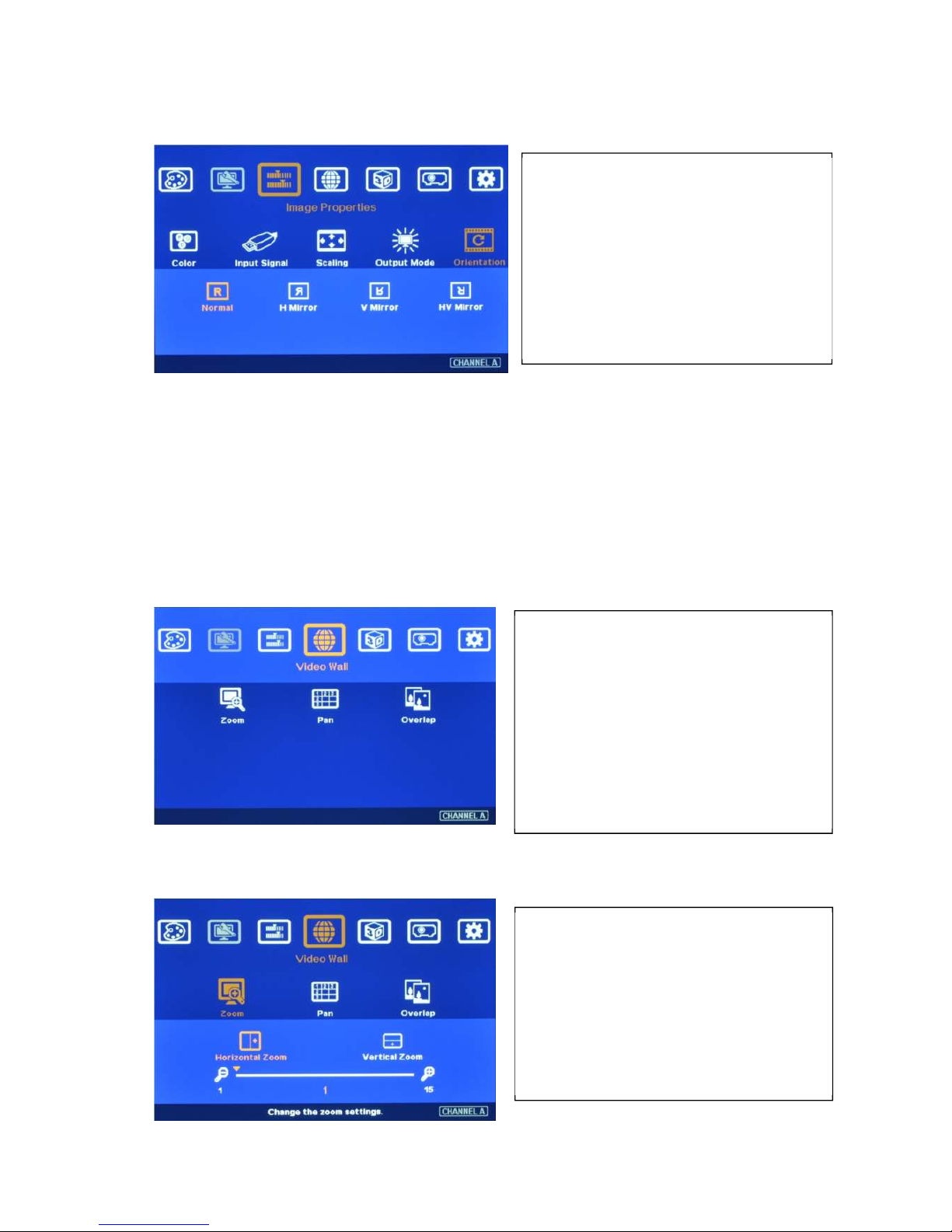
9.5 [Orientation]: image 180〫rotation and flip
10 Video Wall Setting
The purpose for Video Wall Setting is to determine the display Matrix, split the image and assign each
AV-BOX/display device to the right location in the matrix. The overlap pixel between two images can
also be adjusted pixel by pixel so that the video wall can meet the requirements in different application
environment. The maximum video wall can be up to 15x15 matrix display with overlap up to 900 pixels for
edge blending.
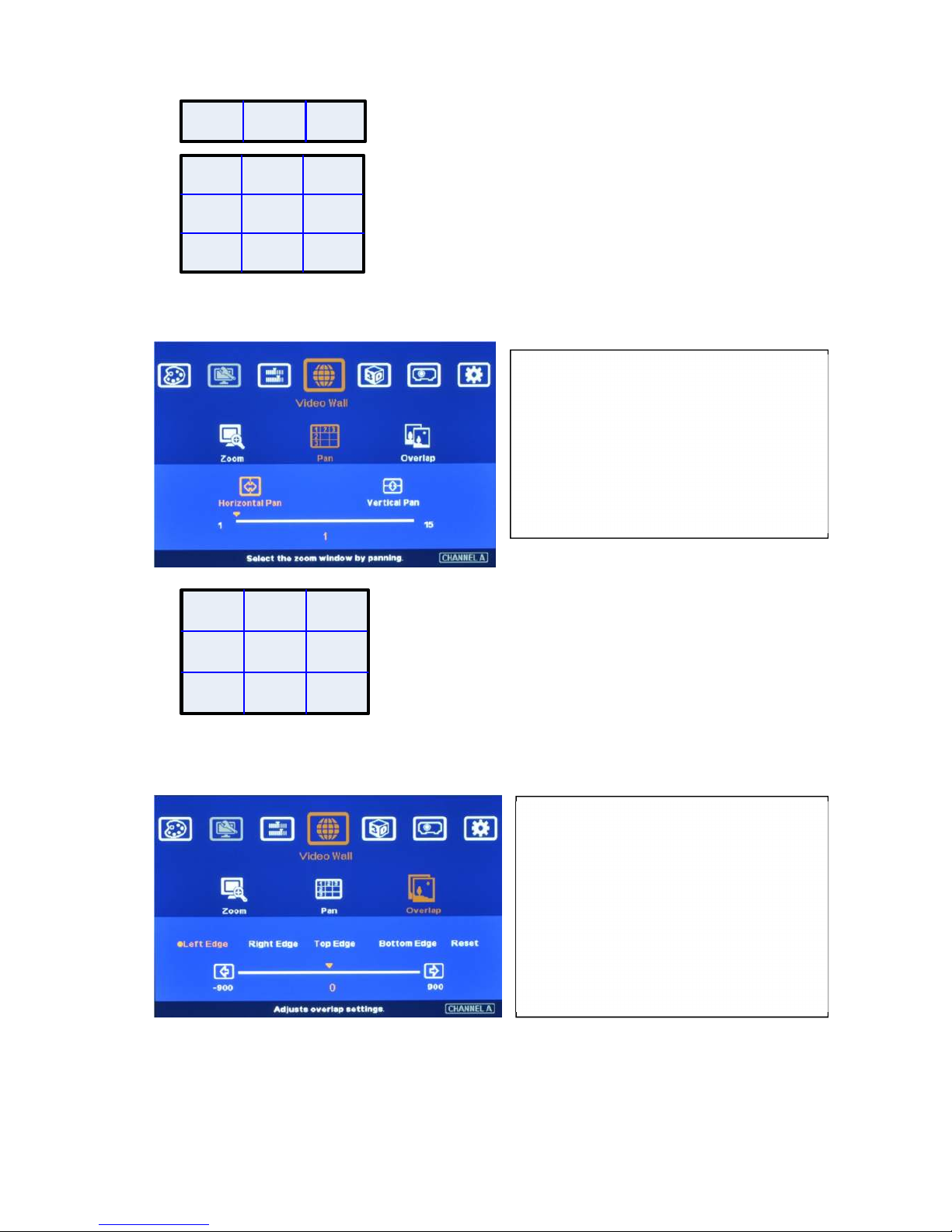
10.1 [Zoom]: split the image
Press Menu Keypad on Front Panel or
remote controller to enter [Video Wall]
OSD menu.
[Video Wall] hotkey on the bottom right
position of the remote controller is
available for quick access.
Video wall function can crop right image
for edge blending and assign to projectors.
Use [Zoom] to split input image in horizontal
and vertical directions. Maximum split image
is 15x15 in both horizontal and vertical
directions.
4 image flip and rotation modes.
User can see the TEXT in the OSD to
select the one that is needed.
If user selects 180〫image flip, the video
wall position setting [PAN] also needs to
be changed. User can see the image
change to select the right position.
Page 22
VWC-44
21
10.2 [Pan]: assign image location
10.3 [Overlap]: to set image overlap pixels
In multiple projector applications, if the overlap region has different size due to installation position
limitation, the overlap value may be different between projectors. However, the total overlap value
should be the same to maintain the same scaling factor.
Please contact us for this kind of irregular overlap condition.
User can use Video Wall overlap setting to fine-tune the image in overlap region. It can
Use [Pan] to determine the location of
each split image in the display in both
horizontal and vertical directions.
Default setting:
Horizontal Pan=1
Vertical Pan=1
Use [Overlap] to determine overlapped
pixels between two adjacent displays. It
will change image cropping area and can
change image aspect ratio.
In projector edge blending, user needs to
select correct Edge to crop the right
image range for each projector.
For No. displays: For No.
displays:
Horizontal Pan = 3 Horizontal Pan = 3
Vertical Pan = 1 Vertical Pan = 2
For 3x1 displays
, Horizontal Zoom=3, Vertical zoom=1
For 3x3 displays, Horizontal Zoom=3, Vertical Zoom=3
Page 23
VWC-44
22
compensate geometry mis-alignment and let image become much clearer.
10.4 Example for three projector edge blending
a、 An Excel Spread Sheet can be provided for the calculation of the Video Wall Overlap setting value.
b、 For dual projector edge blending, user can increase [Overlap] value in each channel at the same
time. Then user will see the overlapped images to come closer till two image 100% match
together.
c、 For dual projector edge blending, user can use below equation to calculate overlap pixel.
Assumption: Input signal:1080p, VWC-44 output to projector: XGA, Overlap 224 pixels (7 grids)
Overlap value=(1920/2)/(1024-224/2)x(224/2)=118 pixels.
11 Passive 3D Display
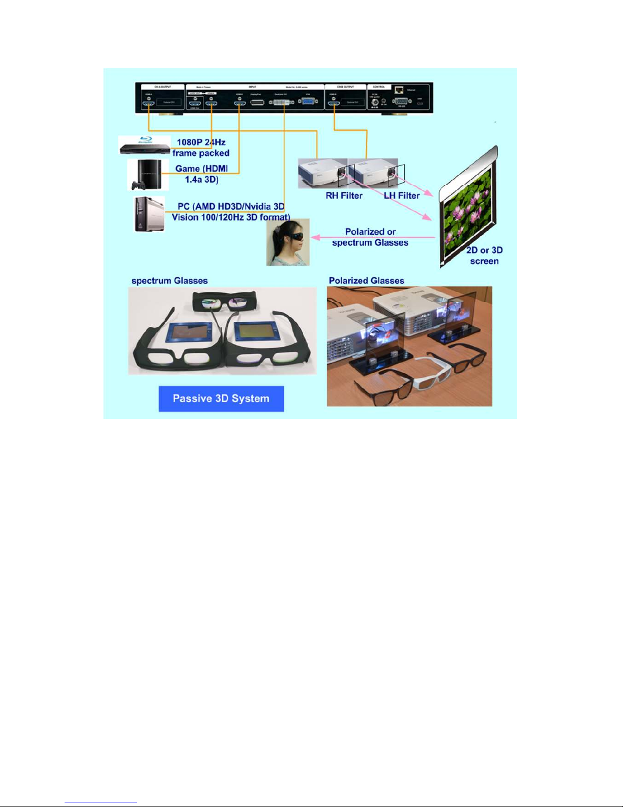
11.1 System Configuration
AV-BOX will decode 3D format from all kinds of 3D video sources, including Blue Ray DVD, STB,
Media player, Game console and PC… 3D signal will be decoded by AV-BOX into signals for Right/
Left eyes. The signal needs to be displayed through two projectors. Each projector will display signal
only for right eye or left eye. User needs to set a polarized filter in front of the projector and also wears
polarized glasses. The glasses need to match the polarized filter in front of the projectors so that the
right eye can only see the scene for right eye and the left eye can only see the scene for left eye.
Silver 3D screen is also required to preserve the polarization of the light for 3D display. It is possible to
use optic spectrum method from Dolby, Infitec or Omega Optical to allow 3D displayed on normal 2D
screen.
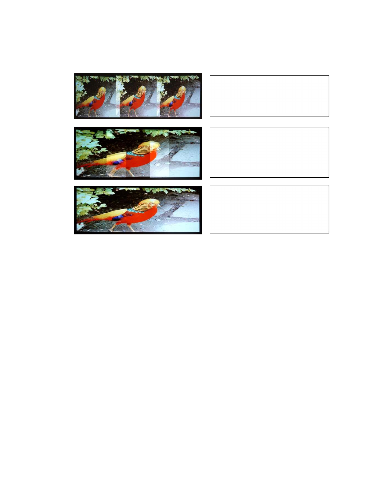
A
fter geometry alignment and [Zoom]
& [Pan].
Double images in overlapped area.
Need to do Overlap setting.
After video wall Overlap adjustment and
a
pply Edge Blending: No more double
image in overlap region and smooth the
uniformity of the color and brightness.
Original images connected to three
p
rojectors before geometry alignment.
Page 24
VWC-44
23
11.2 System installation and setup
a.
AV-BOX should not put at side of the projector where the ventilation hot air comes out.
b. Two projectors can be put side by side or top/bottom. Closer position will reduce geometry
adjustment range and reduce the loss of the image resolution and brightness. Please make sure
hot ventilation air will not affect the other projectors. Isolated board between two projectors can be
added if necessary.
c.
Set higher output resolutions (such as FHD) from 3D signal source and connect to any input
of AV-BOX. AV-BOX will decode and distribute the signals for two projectors.
d.
Each AV-BOX is connected to one projector for right/left eye display.
e. Install polarized filter at some distance from projector lens to avoid thermal damage (at least 5-10
cm).
f. Setup the polarized filter and glasses so that right/left eye can only see the scene for one eye.
g. Use geometry alignment function to align the images from two projectors completely matching
together. Please place the polarized filter in front of the projector before [4 Corner] adjustment
because polarized filter will affect the direction of light beam from projectors. Some deviation is
allowed for 3D display but will affect the performance in 2D display. A good alignment will give double
brightness for the projection in 2D display. For a good double brightness application, two projectors
should be placed as close as possible and the screen must be flat or smooth curve.
Page 25
VWC-44
24
11.3 AV-BOX 3D settings
11.3.1 Input Format]
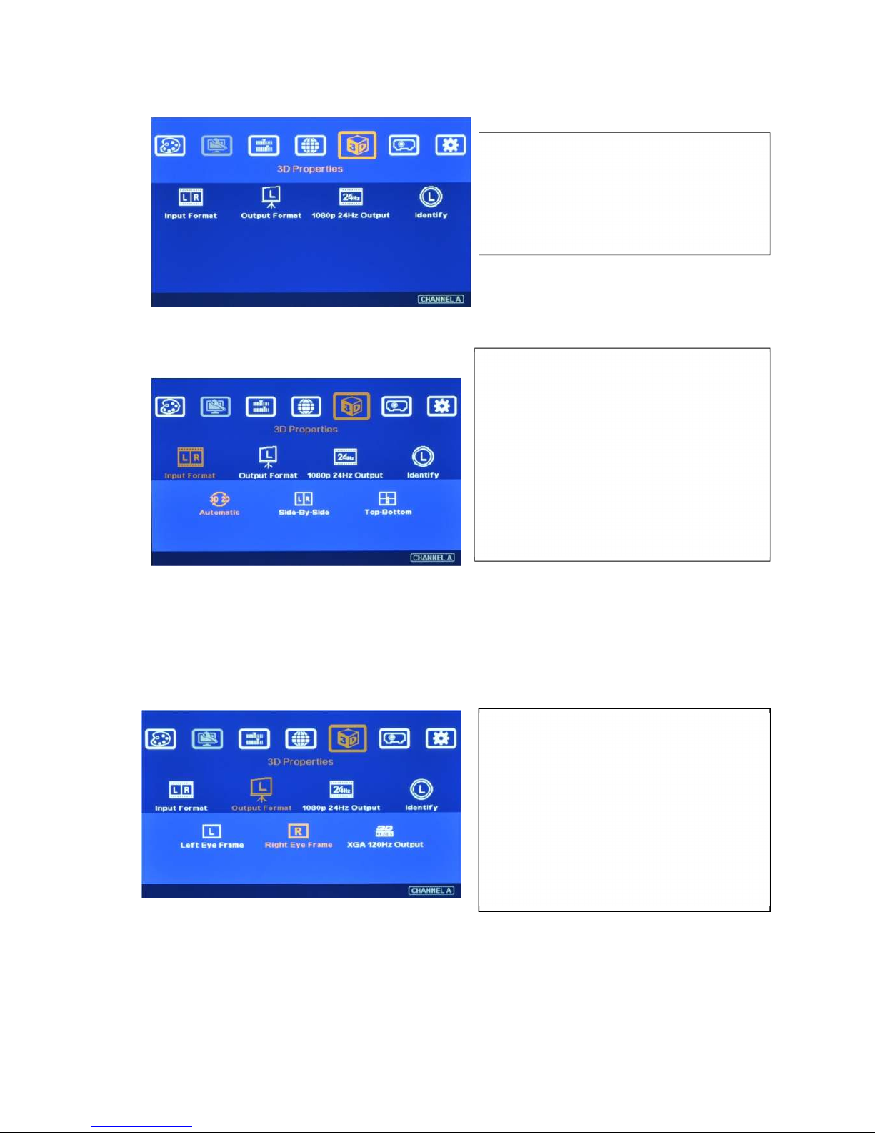
User can set [Side by Side] as normal setting. When the input signal is integrated with [3D INFO],
then VWC-44 can automatically switch to [Automatic] to match 3D input format. Once [Side by Side]
3D is detected, then VWC-44 will switch to [Side by Side] 3D format automatically.
11.3.2 [Output Format]
11.3.3 [1080p 24Hz Output]
If the input is 1080p 24Hz and the projectors can also support this signal with ME/MC processing, please
select [Enable] in [1080p 24Hz Output] to get the best 3D performance.
4 sub-menu under [3D Properties] menu
To set [Right Eye Frame] for RH projector
and [Left Eye Frame] for LH projector.
[Output Fromat] setting is based on the
filter location. If RH optical filter is
installed at LH projector, then user
needs to set LH projector at [Right Eye
Frame]. User can swap [Output Format]
setting to fix wrong position installation
[Input Format] selection:
Select [Automatic] if the 3D signal is
standard 3D formats from Blue Ray player
or sources with 3D INFO inside the signal.
Select [Side By Side] or [Top-Bottom]
based on user’s 3D input sources.
[2D/3D] hotkey on remote controller is for
quick switch among different 3D formats.
Page 26
VWC-44
25
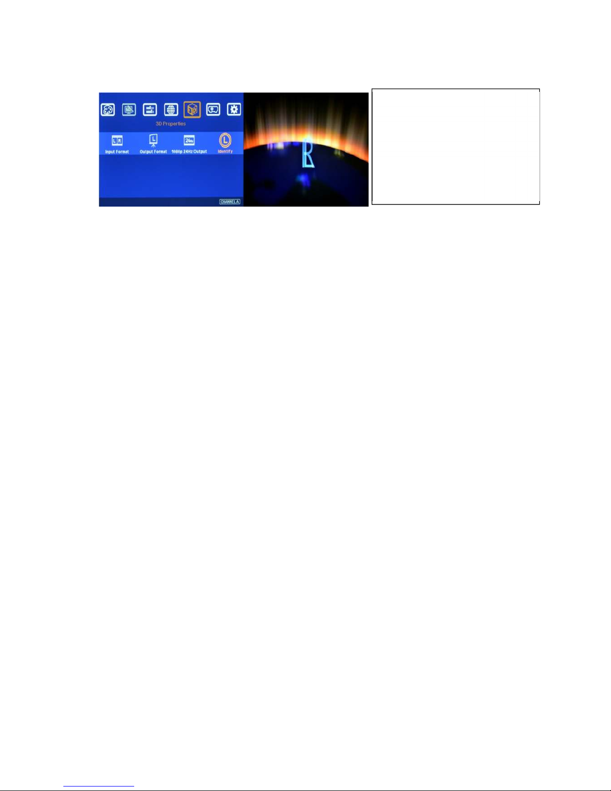
11.3.4 [Identify]: Verify final 3D settings
If still can’t verify “R” & “L” characters in both eyes, please check below again:
Is the screen for 3D display?
Are the Glasses and polarizers the same types and paired for the RH & LH eyes?
Please check from [Output Format] menu and make sure [Right Eye Frame] is connected with RH
eye projector and [Left Eye Frame] is connected with LH eye projector.
Is the Blue Ray player PlayStation set to [Auto 3D] or [1080p frame packing] mode for 3D signal
output?
If Side by Side or Top-Bottom 3D formats are used, please check the aspect ratio in video
source output to make sure AV-BOX will receive full screen image.
Is there any HDMI or signal source compatibility issue and only one projector shows image?
Are the HDMI cables qualified and the length not too long?
After the above procedures, apply 3D signal source and wear 3D glasses, user can enjoy the most
comfortable and healthy 3D system. It is the best solution for children with minimum harm to the eyes.
12 Active 3D applications
For DLP-Link or Nvidia 3D Vision active 3D display, user needs to provide 100/120Hz signal to
projectors integrated with either DLP-Link 3D Ready or Nvidia 3D Vision capability. If multiple projectors
are used, shutter glasses will only synchronize with one emitter among these 3D Ready projectors.
VWC-44 can support 100/120Hz frame sequential 3D signal up to full HD and also 1080p 24Hz frame
packed 3D format from Blue Ray player, execute geometry warp, edge blending or stacking for these
signals and and output 720p or XGA 120Hz signals for active 3D display.
In multiple projector active 3D applications (edge blending or stacking), please select DLP projector with
“3D Ready” function. The projector should be able to select [3D enable] and [3D Sync] functions
separately because only one projector in edge blending can enable [3D Sync] and all the other
projectors shall Enable 3D but turn off [3D Sync] to let the glasses only synchronize with one signal.
Please note that after edge blending in active 3D system, it will not support side by side and top/down
3D signal because once this kind of 3D signals have been gone through geometry alignment, the image
location will be also changed. It can’t show correct 3D effect. Please also note that multiple projector
active 3D system may meet R/L inverse image issue. User needs to swap R/L channel through glasses
or projector.
Activate [Identify] menu to show
“R & L” characters on the screen
simultaneously to verify the final
3D settings in the system.
RH eye should see only “R” and
LH eye should see only “L”.
Page 27

VWC-44
26
The major functions of VWC-44 in active 3D applications are:
a. Geometry adjustment to fit image on to curved screen.
b. Edge blending to enlarge the display with multiple active 3D projectors.
c. Image stacking to enhance the brightness using multiple active 3D projectors.
d. Format conversion: Convert Blue Ray 1080p 24Hz frame packed and PC or Nvidia 3D Vision
1080p 120Hz signals for active 3D display.
e.
AV-BOX can also convert 1080p 120Hz input into 1080p 60Hz output for passive 3D or 2D display.
12.1 Procedures for active 3D Setting
a.
To select the output resolution in AV-BOX to XGA (for XGA projector) or 720P (for projector
native resolution larger than 720P) through front panel or remote control hotkeys.
b. To set 3D output format at [XGA 120Hz output] or [720P 120Hz output] under 3D Properties menu.
c. If user selects other output resolution except XGA or 720P, [3D Ready] menu will be grayed out
and user can’t select 120Hz output.
d. Projector needs to have 3D Ready DLP Link or Nvidia 3D Vision function. This 3D function needs
to be open while playing active 3D.
e. It is possible for user to see inverse image in R/L eyes’ image. User need to swap R/L signal
through projector internal function [3D Sync Invert] or active 3D.
Page 28
VWC-44
27
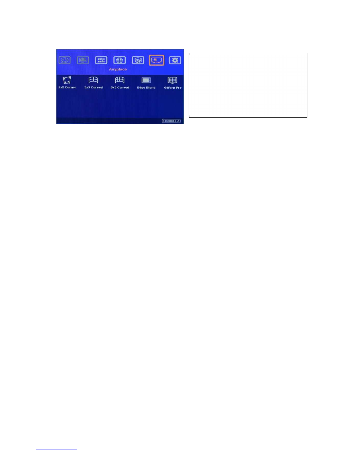
13 [Anyplace]: Geometry Correction and Edge Blending
a、 [2x2 Corner]、[3x3 Curved] & [5x3] Curved] are for manual geometry alignment through OSD
menu.
b、 [Edge Blend] provides all the functions for seamless high performance edge blended
image. c、 [Gwarp Pro] is to recall the setting from [Gwarp] PC tool and store in AV-BOX.
13.1 Geometry adjustment range
a、 The adjustment range is calculated based on the percentage of output resolution in AV-BOX
setting. Therefore, higher output resolution will have more adjustment pixels.
b、 Under XGA output resolution, the adjustment range are as follows:
--[2x2 Corner] adjustment in one side: Horizontal: 150 Pixels, Vertical: 100 pixels
--[3x3 curved] & [5x3 Curved] adjustment: Horizontal: 150 Pixels, Vertical: 100 pixels
--Maximum adjustment range in one side: Horizontal: 300 Pixels, Vertical: 200 pixels
--Maximum adjustment range in both side: Horizontal: 600 Pixels, Vertical: 400 pixels
c、 Under WXGA & 1920x1200 output resolutions, the adjustment range are as follows:
--[2x2 Corner] adjustment in one side: Horizontal: 300 Pixels, Vertical: 200 pixels
--[3x3 curved] & [5x3 Curved] adjustment: Horizontal: 300 Pixels, Vertical: 200 pixels
--Maximum adjustment range in one side: Horizontal: 600 Pixels, Vertical: 400 pixels
--Maximum adjustment range in both side: Horizontal: 1200 Pixels, Vertical: 800 pixels
d、 Gwarp PC tool has double adjustment range than manual adjustment.
13.2 Procedures for geometry alignment
a、
User can select the procedures based on different application and conditions. If the
application is for flat screen, then [2x2] alignment will be quicker and enough.
b、 If curve alignment is required or the flat screen is not flat enough, user can use [2x2]
alignment to draw the corner positions to expected locations. Then apply [3x3] alignment to
alignment the outlines of the image to the required positions following with [5x3] alignment to
do position fine-tune.
c、
Once finish [3x3] and [5x3] alignment, user can go back to [2x2] alignment to fine-tune the
corner positions.
d、 After [5x3 Curved] alignment, it still can’t meet expected result or manual adjustment range is
not enough, user needs to apply Gwarp PC Tool for the geometry alignment.
Under [Anyplace] menu, it provides below
f
unctions:
Geometry alignment, including recall
Gwarp PC tool geometry alignment result.
Edge blending and image color correction.
Page 29
VWC-44
28
e、 [Gwarp] PC tool can apply [5x5], [9x9] and [17x17] grid pattern adjustment. It will also have
double geometry adjustment range.
13.3 [Reset] in geometry alignment
a、 After finish [3x3] and [5x3] alignment, user can go back to [2x2] alignment to fine-tune the
corner positions and it will not affect [3x3] and [5x5] adjustment result.
b、 If user finishes [3x3] & [5x3] adjustment and go back to [3x3] menu, then it will reset the
adjustment in [5x5] adjustment and only keep [3x3] adjustment result.
c、 If user press [Reset] key in [3x3] adjustment, all the adjustment in [3x3] and [5x3] will be reset
and only [2x2] will be kept.
13.4 Important notice for geometry alignment
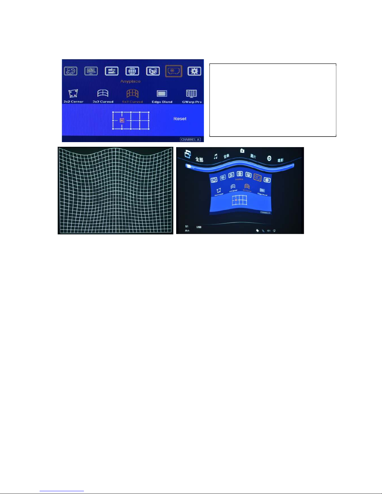
a、 [5x3 Curved] will cut the horizontal image into 4 sections and the image in each section can be
independently adjusted. In different output resolutions, there will be different pixel number:
XGA: 1024/4=256 (8 grids), WXGA: 1280/4=320 (10 grids), 1080p: 1920/4=480 (15 grids). If
the overlapped area between two adjacent projectors has the same pixel number as above,
then the manual geometry alignment for grid overlap will have less flexibility. The alignment
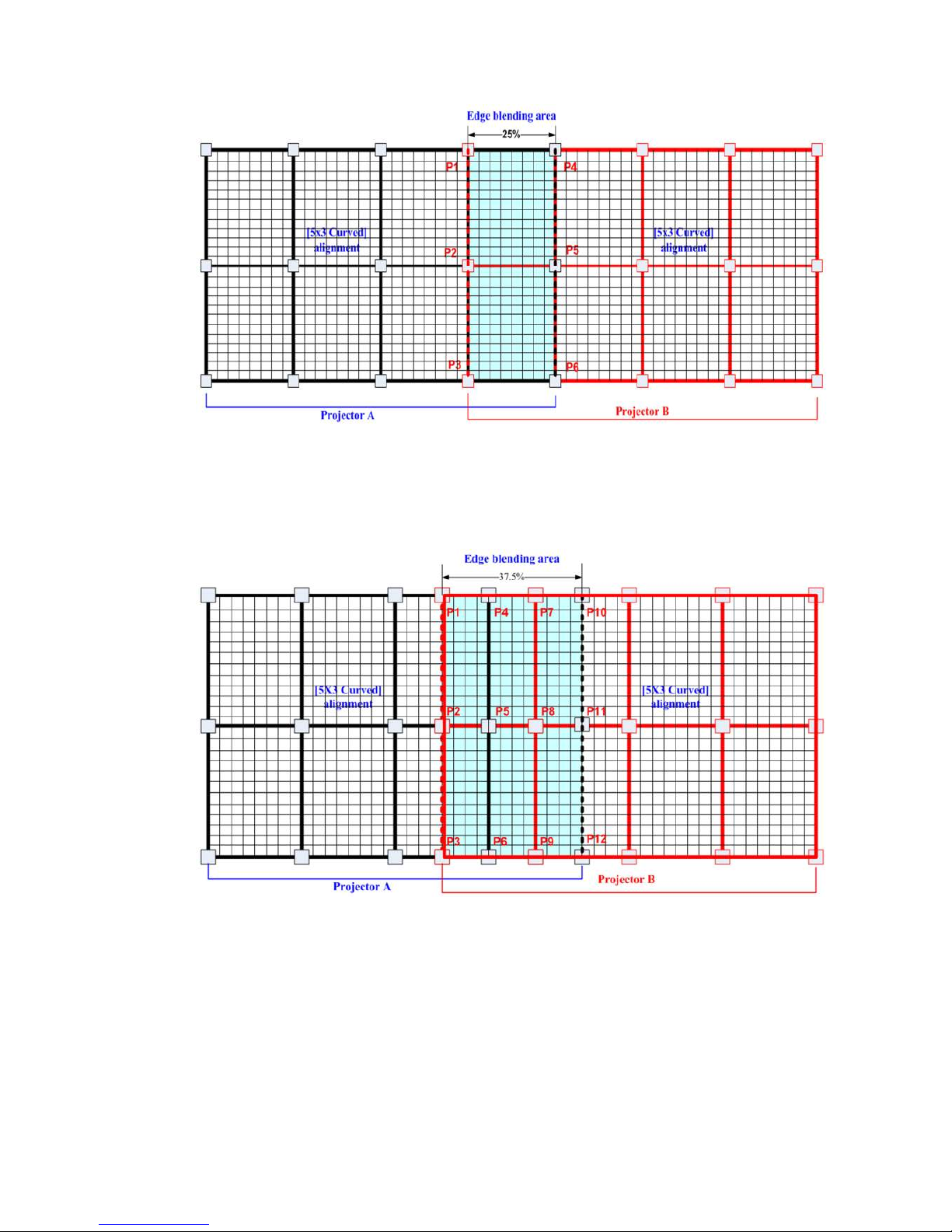
points in edge blending area will be only 6 points (P1~P6) and user can’t do further adjustment
inside area blending region.
User can see the grid location for
geometry alignment on the screen.
User can use remote controller or front
panel keypad to change grid location.
When adjusting each grid, the other grids
will maintain at the same location.
Page 30
VWC-44
29
b、 If the overlap can have 1.5x as above :XGA: 384 (12 grids), WXGA: 480 (15 grids), 1080p: 704
(14 grids) then user can get the most flexibility for geometry alignment. The alignment points
will become 12 in edge blending area. It can align the images from two projectors on curved
screen with good alignment without Gwarp.
c、 We suggest the overlap pixels can be +_2-6 grids (64-192 pixels) deviation for easier manual
alignment on curved screen.
d、 If alignment by Gwarp PC Tool, there is no limitation in the overlap grid number because it can
execute up to 17x17 grid patterns.
e、 Once the grid between two adjacent projectors can match together, it will make sure to get
good alignment. Horizontal lines between two adjacent projectors should be 100% match
together. Vertical lines are allowed to be separated. However these vertical lines should keep
the same gaps between two adjacent projectors. User can adjust Video Wall [Overlap] value to
compensate the gap distance and get crisp image.
Page 31
VWC-44
30
13.5 [Edge Blend]
a. Edge Blend is to merge the images from multiple projectors to become one seamless image.
b. The scaling factor between two adjacent images shall be the same. Otherwise, it will become
blurred. It means the image size under the same resolution should be the same.
c. Geometry alignment is required before edge blending:
To let the image has the same grid size (same scaling factor in both horizontal and vertical
directions)
To let the images overlap together in horizontal lines
d. Sub-menu under [Edge Blend] menu
[Edge]: select the right edge and set overlap pixels
[Gamma]: select correct gamma for overlapped area and [Offset] compensation area to
eliminate banding effect.
[Offset]: to do black level uplift in non-overlapped area to compensate light leakage in
projectors.
[Corner]: to do precise [Offset] location alignment.
[Shift]: shift the location in edge blend area. In some case, it may help color fine-tune.
[Color]: to do discrete color adjustment for individual projector.
13.5.1
[Edge] selection and settings
a. [Edge] is to select the edge for edge blend and set overlapped pixel number.
b. It can do edge blending at any edge.
c. Maximum edge blend pixels are 900. If over this number, please consider using image stack or
change aspect ratio in projector to shrink projection image. User can also reduce edge blending
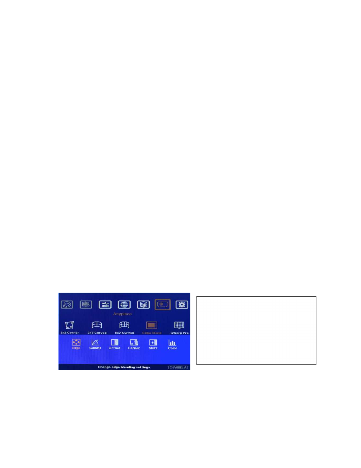
area by geometry alignment in two vertical borders of edge blending area. Each projector shall
reduce the same pixels and maintain the same image size and scaling factor.
Color indicating lines will appear when
set edge blending pixels.
User only needs to adjust the color
indicating lines to match together
(green to green, red to red). There is no
need to calculate the overlapped pixels.
Page 32
VWC-44
31
13.5.2 [Gamma]: Color correction in edge blending area
a、 Different projectors may have different gamma curve. Different “Display mode” in the same
projector will also have different gamma curves. These gamma curves will affect the final video
result in edge blending area. The common issues are gray or color banding effect. These issues
are more significant in pure color or white back ground display.
b、 [Gamma] is to select the right gamma curve for edge blending area and [Offset] compensation
area.
c、 If color difference in the projectors, user need to adjust the color difference in the projectors to
reduce the possible banding effect in edge blending area due to color different among projectors.
d、 [Gamma] function is not functional when [Edge] setting is not executed.
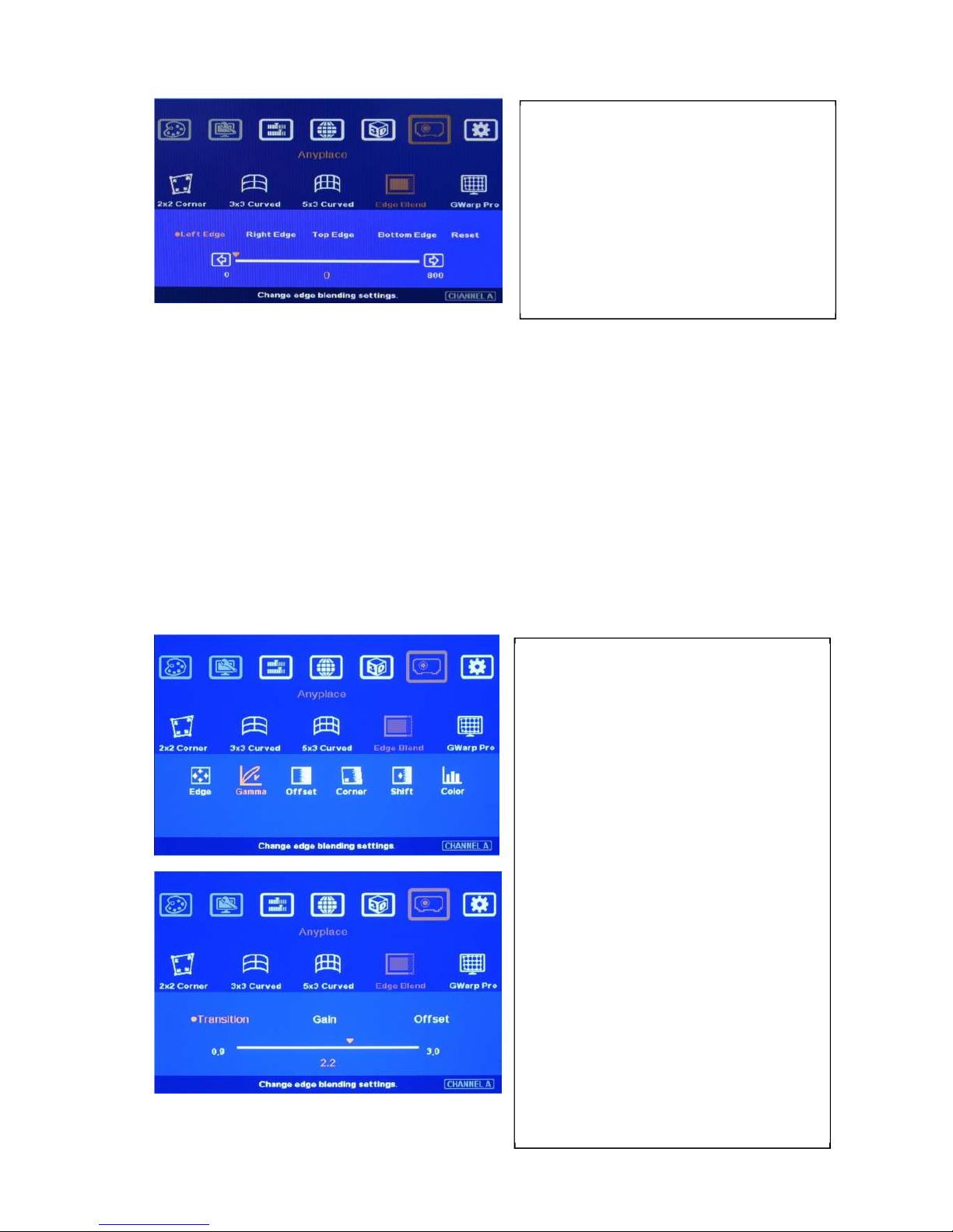
User needs to select correct edge for edge
blending.
For 3 projector edge blending as example:
To select [Left Edge] for RH projector
To select [Right Edge] for LH projector
T
o select both [Right Edge] & [Left
Edge] for center projector.
Two sub-menu under [Gamma]:
[Transition]: To set edge blending area
gamma value. User can see image
color change in edge blending area
real time to get the best quality.
[Gain]: To fine tune the gamma curve
in edge blending area in each channel
near the center point of gamma curve.
It can further improve edge blending
result, especially while two adjacent
projectors has different gamma curve.
[Offset] gamma: To prevent black level
Offset adjustment from affecting
normal image brightness while
executing black level uplift. It will
determine the control curve in offset
adjustment. Basically, offset
adjustment is to adjust the color at low
brightness level only. It is related to the
Page 33
VWC-44
32
Please note:
e、 Banding effect in edge blending area is related to projector color setting and gamma curve. The
projector should have the same gamma setting and [Display Mode].
f、 Please disable [Dynamic] color or [Brilliant] color function in the projectors. These function will
change gamma curve based on the content and affect final edge blending image quality.
13.5.3 [Offset]: Black level uplift
If edge blending is performed under dark environment, due to light leakage in projector optical
system, user will see gray area in overlapped area. This gray area can’t be fixed by signal
processing. The only way is to uplift the black level in non-overlapped area to reduce the black level
difference. [Offset] function is to balance black level in the display under dark environment.
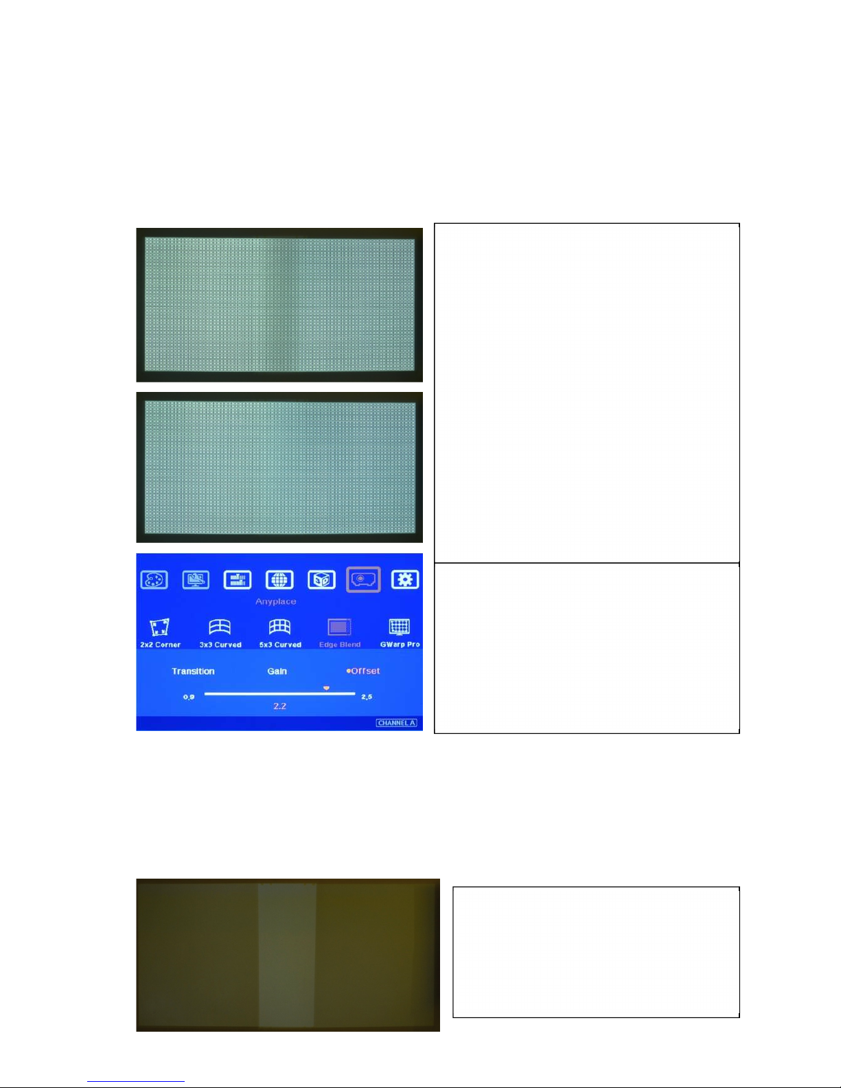
Left picture is to show projector light leakage
under dark environment. In overlapped area,
the offset value is the sum from two projectors.
Low contrast ratio projector will be more
serious.
Left picture is to show banding effect in edge
blending area.
This issue is related to many factors:
Screen: gain value under 1.5 is recommended
Projector: should be the same model with the
same gamma and Display Mode settings.
Usually DLP projector will get better result.
Signal content: To avoid pure color or pure
white color content. Multimedia is the best.
Overlap range: too small overlap range will be
easier to see banding effect. 15%-25% with
more than 40 cm is recommended. (XGA: 6-10
grids, FHD: 10-20 grids, each internal pattern
grid size is 32 pixels)
When adjusting black level, [Offset] value will be
applied to complete color range and reduce image
quality. [Offset] gamma adjustment can avoid this
issue and let [Offset] adjustment only affect black
level but not complete image.
Page 34
VWC-44
33
The starting point for this Offset is based on Edge blend borders. The projector light leakage area is
from the original projecting area before geometry alignment. Therefore Offset borders may not be
the same as light leakage area. User needs to use [Corner] menu to align the border lines for Offset
adjustment.
13.5.4 [Corner]: Adjust [Offset] compensation position
a、 After set [Offset] value in [Non-Transition] area, user can reduce the black level offset difference
but user will also see small light bar near edge blending border. Below is the reason:
The starting point of [Offset] for non-transition area compensation is based on Edge Blend
borders after geometry alignment. The projector light leakage area is from the original projecting
area before geometry alignment. Therefore Offset borders may not be the same as light leakage
area. User needs to use [Corner] menu to align the border lines for Offset adjustment.
b、 The maximum range for the corner adjustment is 300 pixels. When user installs the projectors,
please make sure the projector projecting area border to be as close as actual edge blending
border. The maximum difference should be under 300 pixels.
c、 Projector display imager, such as DMD, LCD and LCOS, will have some image borders due to
active display window is not at full range of the imager. In dark environment, viewer may see this
kind of uplift in black level. Usually, except near edge blending area, this kind of black level uplift
is outside the display area (outside screen frame) and viewers will not see it. However, when the
projector is displayed on a screen without borders, Viewers may see this black level uplift. It is
outside active display area and can’t be corrected.
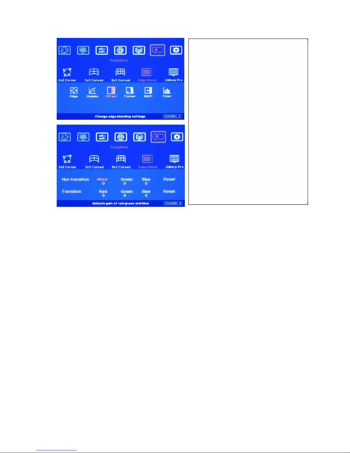
User can find [Non-transition] and
[Transition] offset adjustment menu。
Under each menu, user can adjust RGB
offset value in Transition and Non-
transition area to balance the color
difference.
Usually, user needs to raise RGB offset
value in Non-transition area (about 20-40
in DLP and 50-70 in LCD projector).
Once color difference is found, user
needs to adjust different RGB offset
value on Transition and Non-transition
area to eliminate the color difference.
User can adjust color in [Transition] area
but can’t reduce the level. It is light
leakage from projector.
Page 35
VWC-44
34
13.5.5 [Shift]: Edge blending area shift
13.5.6 [Color]: Individual projector white balance and color correction
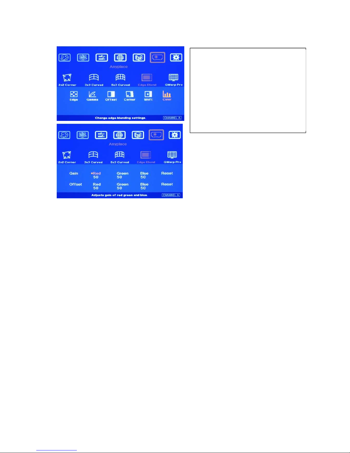
The [Color] adjustment can be applied to individual projector for white balance and color difference
correction through separate RGB Gain and Offset adjustment. It will be very helpful in projector system
because projector may have color difference, lamp brightness decay and lamp replacement issue.
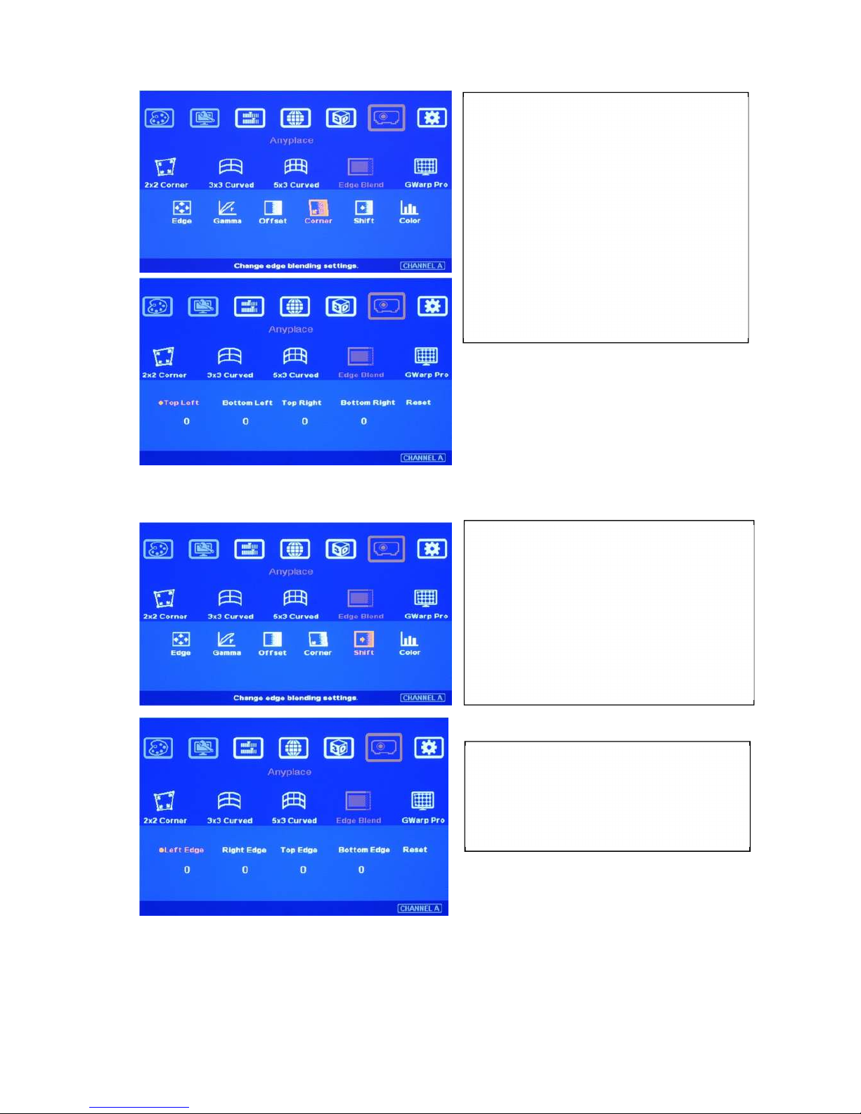
[Corner] can adjust the positions for black
level [Offset] borders through change the
end points of the borders.
Geometry alignment on the borders of
edge blending area should be ver
y
a
ccurate. Otherwise [Offset] position in
black level uplift will be affected.
User can adjust the top and bottom points
to get accurate positions.
[Shift] is to shift the whole edge blending area
to other location. The width of the edge
blending area will remain the same and only
change the position. This is to test the effect of
banding effect and select the best location of
the edge blending.
The maximum range for the adjustment is
250 pixels.
Page 36
VWC-44
35
Through this [Color] adjustment, it will improve the video quality in edge blending.
In edge blending procedures, firstly, user needs to adjust the color from projector. If it is still not enough,
user can use [Color] function to do further adjustment. Please note that, any color adjustment will reduce
the color dynamic range. User needs to check the result with full range color image.
13.6 [Gwarp] PC tool
[Gwarp] PC tool is provided to do more detailed geometry alignment, color uniformity adjustment and
advanced edge blending color fine-tune. User can combine [Gwarp] tool result with AV-BOX
hardware function to achieve edge blending project.
13.6.1 When [Gwarp] PC tool is necessary
VWC-44 hardware system can execute complete edge blending function without [Gwarp] PC tool. In
below conditions, Gwarp PC tool may be still necessary in edge blending operation.
a. The grid pattern for manual geometry alignment is up to 5x3 only. It can meet most of the application
requirements. However, if the screen is irregular curve or more precise alignment is required, then
Gwarp PC tool is needed for further geometry alignment.
b. More geometry adjustment range is required. Gwarp has double geometry alignment range.
c. In the long term, Gwarp will provide more function for the applications, such as auto geometry
a
lignment, auto edge blending and more intensive color correction.
13.6.2 System configuration
a. The package of Gwarp PC tool includes [Windows Driver] & [Gwarp.exe file]. Please unzip the file
and install USB driver.
U
nder [Color] menu, user can adjust
separate RGB [Gain] and [Offset] value to
change the color and white balance.
[Gain] is to change the color slope and
[Offset] is to add value in all level of
brightness (0-225).
User needs to adjust [Gain] for white
balance.
Page 37
VWC-44
36
b.
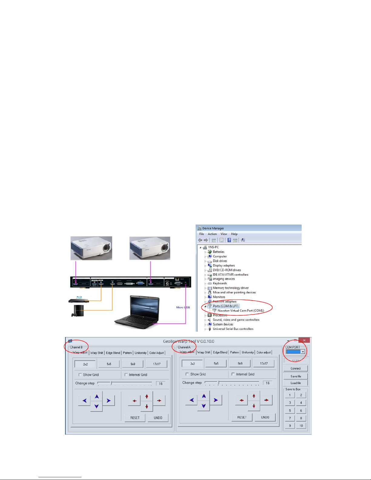
One PC can control two VWC-44 output channels for two projectors. If more projectors are used,
user can use multi-PC or finish two projector alignments first, freeze the grid pattern in the
projector, then align the next two projectors.
c.
VWC-44 is connected with PC through Micro USB interface.
d. Gwarp consists of two PC operation windows for channel A & channel B in one PC.
e.
After open Gwarp, VWC-44 will be reset and controlled by Gwarp PC tool. If only one projector
needs Gwarp alignment, user can activate OSD and access to 5x3 warp alignment in the channel
that user doesn’t want to change, then it will show original manual alignment pattern for further
operation.
13.6.3 Gwarp operation: Only work with Windows 7 OS
13.6.3.1 System connection
Connect VWC-44 and PC via Micro USB cable.
Unzip Gwarp file and install Nuvoton USB driver in PC with Windows 7 OS.
Check Device Manager to confirm correct USB driver installation.
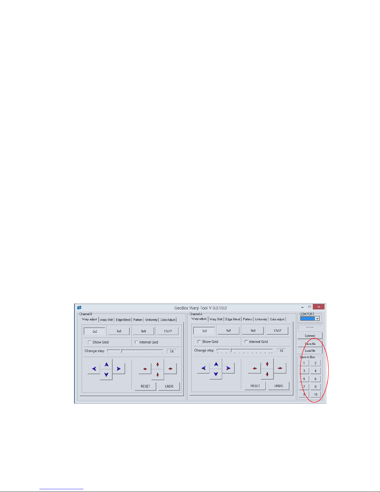
Open [Gwarp.exe]. Click [Connect] to connect COM port. After connection, it will show input signal resolution
and [Disconnect] icon. We propose to apply 1080p signal to VWC-44 for easy system setup.
There are two operation windows for Channel A & Channel B control.
Page 38

VWC-44
37
13.6.3.2 [Warp adjust]
Click [Pattern] and select one color and Enable test pattern to show grid pattern on the screen. The
pattern default grid size is 32x32 pixels and it can be changed as needed. User can also neglect this
step to show signal image on the screen.
Select [Warp adjust], grid type and adjusting Step (default is 16 pixels) for the adjustment. BLUE
direction keys are for control point selection and RED direction keys are for value adjustment.
[2x2] alignment is for quick image corner alignment. Usually, user needs to apply [2x2] geometry
alignment first to draw image 4 corners to the required positons, then go to [5x5] or [9x9] for further
geometry alignment. After [5x5] or [9x9] alignment, if user goes back to [2x2] alignment, then only
[2x2] alignment will be reserved and all other alignments will be reset.
For most of the applications, we propose to follow [2x2][5x5][9x9][17x17] sequence for
geometry alignment. Please note that if you execute [9x9] or [17x17] and back to [5x5], it will only
keep [5x5] data and reset all the rest.
In each grid alignment, if only click [Show grid], it will only execute image outline position adjustment.
The center image will be changed proportionally with outline position.
To click [Internal Grid] will limit your adjustment within internal grid area. Usually, it is for detailed
image position fine-tune.
For edge blending, please align all the grids in edge blending area stacked together to ensure clear
image can be obtained.
After finish geometry alignment, user needs to execute [Video wall] setting and [Edge Blend] in
AV-BOX hardware system to complete the whole edge blending process.
13.6.3.3 [Warp Shift]
[Warp Shift] is one function for image 4 corner position fine-tune. The major difference from [2x2]
adjustment is that [Warp Shift] can do 4 corner adjustment but still keep the setting in other [Warp
Adjustment]. This function is good for below operations:
a、 Final image 4 corner position fine-tune without affecting other warp adjustment
b、 After lamp change or long term deformation of the mounting rack, user can easily apply [Warp
Shift] to align the projector back to original position without changing image curve.
c、 Convenient for after service—save time and money.
13.6.3.4 [Edge Blend]
It is to set the right location and pixel number for edge blending based on geometry alignment.
To align the color in edge blending area through Gamma adjustment.
To execute [Offset] to do black level uplift.
This function can be implemented through AV-BOX hardware system independently.
13.6.3.5 Color [Uniformity] correction
Page 39
VWC-44
38
User can set different gain and offset value in RGB separately to do uniformity adjustment.
The minimum area for color uniformity adjustment is 64x64 pixels.
13.6.3.6 [Color] adjustment
Color adjustment is to do white balance and color correction in individual projector. User needs to try
color adjustment from projector first. If it is still can’t fix color difference, user can use [Color] function
to do independent RGB Gain and Offset adjustment.
Any color adjustment will reduce the color dynamic range.
13.6.3.7 [Save File] & [Save to Box]
After finish Gwarp operation, user can save the result in two locations--PC and AV-BOX.
Click [Save file] will save the file inside PC and need to use press [Load file] to load back settings.
Click the # under “Save to Box” will save Gwarp result into VWC-44. User can create up to 10
different Gwarp results into AV-BOX.
After save the file, please disable [Pattern], [Show Grid] and [Internal Grid] in Gwarp so that user
can see the system OSD through keypad or remote controller.
Next step is to activate AV-BOX OSD to load Gwarp result under [Anyplace][Gwarp] menu.
Please load Gwarp results separately through OSD operation. In case user only needs to do
Gwarp adjustment in one channel but not both, please only load the one that you need. User can
access to [5x3 Curved] menu to activate original manual warp settings.
Please combine with [Video Wall] and [Edge Blend] functions through OSD to complete edge
blending processes. User can save the final result into [Profile] menu and recall it at any time.
Maximum 5 profiles can be saved.
Once select [Gwarp] geometry alignment result, all the geometry alignment result will be replaced.
Please note that current Gwarp version has below limitations:
1. It can only work with PC with Windows 7 OS.
2.
Only Geometry Warp data can be stored to VWC-44.
3. If the application is edge blending, the [Video Wall] and [Edge Blend] settings shall be executed
in hardware system through remote control or front panel keypads.
Page 40

VWC-44
39
4.
HID interface will be used in VWC-44 in the future. At that time, user will be able to control
Gwarp through USB, Ethernet or WiFi.
13.7 Example for 3 projector edge blending setup
Edge Blend can enlarge the display screen and change the aspect ratio using multiple projectors.
Three elements are required for edge blending: One is to do geometry alignment and let all images
from the projectors have the same size. Secondly, to use Video Wall function to split the input signal,
crop the right portion and assign to each projector. The third is to do edge blending to become
seamless image and do color fine-tune. Below is example of the procedures for three projector edge
blending.
a、 Excel Spread Sheet is available to for user to determine the projectors (resolution, quantity, lumens
and throw ratio) and information for system installation (single projector image size, overlap area size,
installation distance and optimized content resolution…). Based on this information, user can make
detailed project plan for the complete system.
b、 Placement of the Projectors:
Select projectors with higher contrast ratio (above 3000:1 is recommended) and set projectors at
reasonable distance from the screen with 200-500 overlap pixels (or 30cm-50cm overlap width)
between two projectors.
Use removable tape as temporary marks to indicate the image edges for each projector and
screen center line (based on the data from Excel Spread Sheet). Each projector should have the
same display size. Otherwise the grid size in each projector will be different and the blending
image will become blurred.
To display each projector a little over the display range for further geometry adjustment.
Please try to install the projector with less keystone image.
To set parallel vertical overlap edges between 2 adjacent projectors and let the positions of the
lines close to pre-marked positions will get better video quality.
c、 Projector setting:
Reset projector to default setting.
To disable “Auto Alignment” function if user wants to use VGA analog input signal to avoid image
shift during projector switching ON/OFF process.
Disable Auto Keystone function.
Select a Display Mode with 2.2 gamma curve will reduce the color difference in overlap area.
User needs to test with different Display Mode setting based at final color fine-tune stage.
Use projector internal color adjusting function to adjustment the color variation among projectors
before implement edge blending.
d、 VWC-44 Setting
Reset AV-BOX to default setting.
Select output resolution to be the same as projector native display resolution.
Set [OSD Time Out] to [OFF] to maintain the display of OSD and Grid Test Pattern during the
Page 41

VWC-44
40
installation period (default is in [Off] position).
To do [Color] adjustment for each projector if necessary.
e、 Geometry Adjustment:
Please be familiar with OSD operation from front panel and remote controller, including activate
grid pattern, channel A/B switching and shortcut keys for [Warp], [Video Wall], [Edge Blend] and
[Info].
[OSD Time Out] is default to ”0”. It will ensure the grid pattern will not be turned off automatically.
If multiple units of AV-BOX are used and IR receivers are put together, please set [Box ID]
for each VWC-44 so that user can control each VWC-44 separately.
Use [Pattern] & [CH A/B] hot key to show grid patterns in all projectors. If two or more AV-BOX
models are used at the same time, user needs to use external grid pattern because the grid
size in VWC-44 is 32x32 pixels and 50x50 pixels in other models. User can set VWC-44 grid
pattern with 50x50 pixels while using Gwarp and no external pattern is required.
Apply [2X2 Corner] geometry alignment and draw the corners to expected locations.
Apply [3x3 Curved] geometry alignment to do further corner, edge and center line position
adjustment through 9 adjustment points.
If user doesn’t use Excel file to calculate the image size for each projector, please try to set the
same image projection height prior to geometry adjustment. In this case, the image width for all
projectors will be also similar. The next step is to do manual projector position adjustment with
reasonable overlap pixels.
If user finds the grid size between adjacent projectors is different. It means the projection image
sizes between two projectors are different. User can adjust vertical center line position by [3x3]
adjustment to correct the grid size and let them have the same grid size.
Please use [5X3 Curved] for further geometry alignment and fine-tune.
All horizontal lines should be matched together and two vertical border lines in edge blending
region should be vertically stacked. In ideal condition, all grids between two adjacent projectors
should be overlap together. In some special case, the vertical lines in edge blending area have
some deviation and can’t match 100%. User can adjust [Overlap] value to compensate this
deviation and keep reasonable image quality.
After the above processes, if the grid pattern in edge blending area still can’t stack together, then
[Gwarp] PC tool should be applied. Before using Gwarp tool, please store manual settings into
[Profile] temporarily.
Please check grid number in overlapped area and make sure two adjacent projectors shall
have the same grid number. If the number is different, please shift the image to reduce grid
number to be the same as another projector. While the image has been shifted, user needs to
divide the shifting pixel number into each sections of the image to balance the grid size in the
whole image. Below example is to shift P4 to left with 30 pixels, then P3 vertical line should be
shifted to left at 20 pixels and P3 should be at 10 pixels. User can continuously press [Pattern]
key until see the adjusting value in OSD or counting the shifting number while shifting the
Page 42
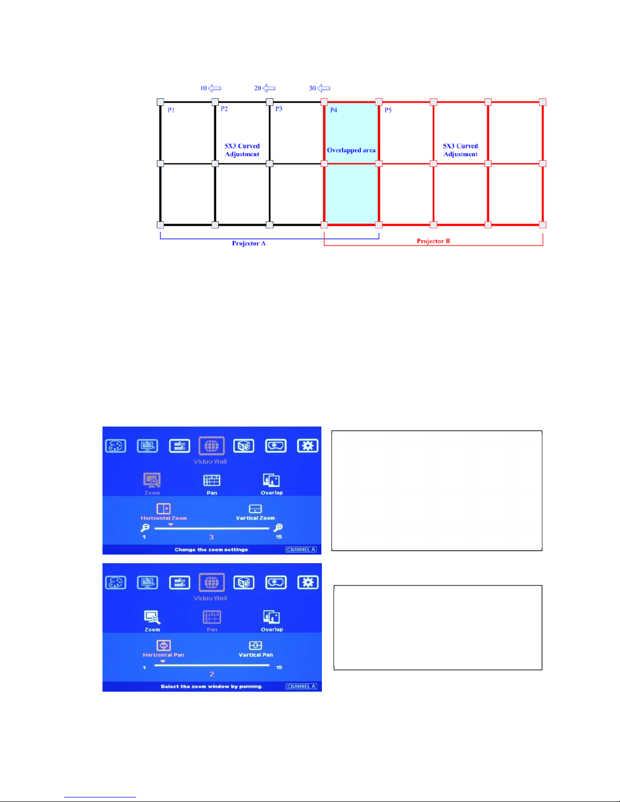
VWC-44
41
pixel position.
If the manual geometry adjustment can’t stack the grid in overlapped region even two
adjacent projectors have the same grid number, user needs to use Gwarp PC tool for the
adjustment.
f、 Video Wall setting (Image split and allocation)
After geometry adjustment, video wall setting is required. The functions of video wall are as follows:
Split the image for different projectors (Zoom)
Determine the location of the image for each projector. (Pan)
To set proper overlap region in the edge between projectors (Overlap)
Example for 3x1 horizontal edge blending Video Wall setting
[Zoom] setting
Select [Horizontal Zoom] [3] to split the
image for 3 projectors horizontal edge
blending.
Select [Vertical Zoom] [1] because onl
y
o
ne projector in vertical position.
[Pan] setting
Select H=1, V=1 for LH projector
Select H=3, V=1 for RH projector.
Select H=2, V=1 for center projector
Page 43
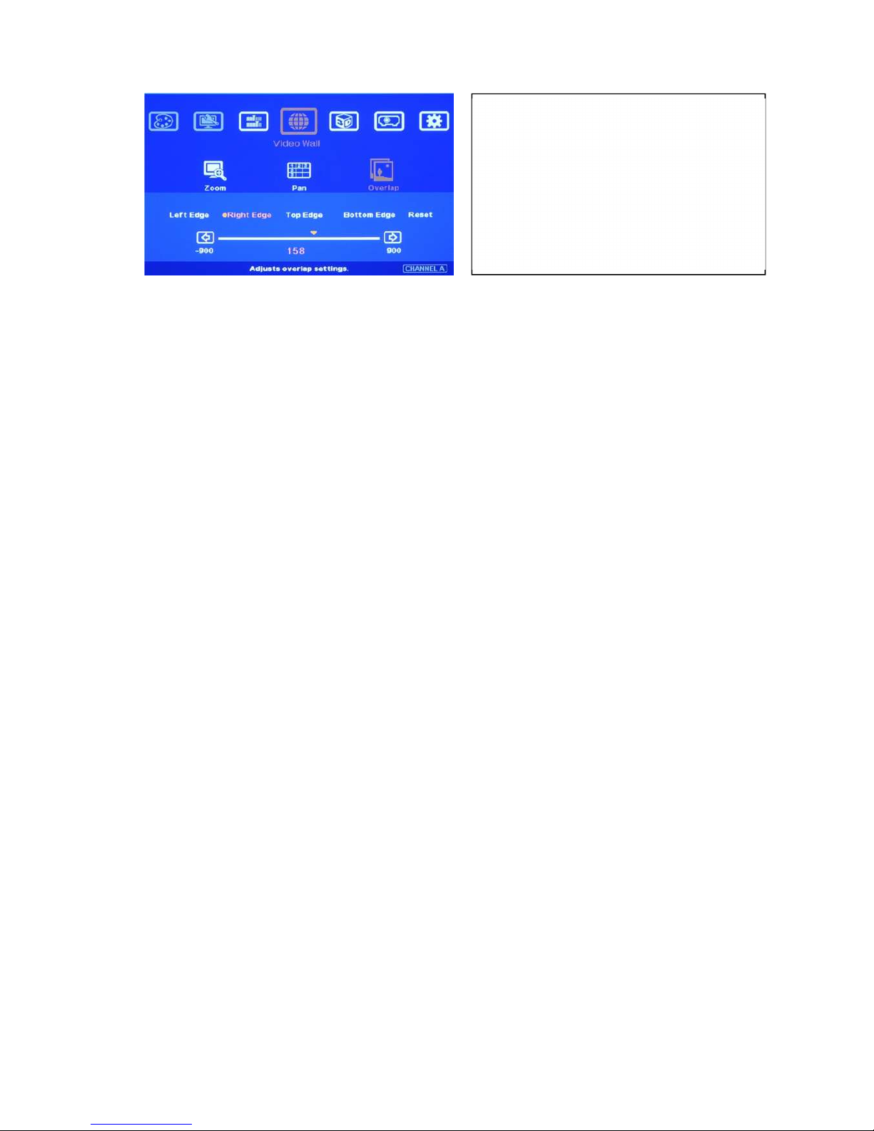
VWC-44
42
Before Overlap adjustment: Double image will be showed in all overlap regions. User can apply
[Overlap] value to eliminate double image at the overlap region.
An [Excel Spread Sheet] can be provided for the calculation of the [Overlap] setting value in
different setup, including different [Overlap] size among different projectors.
For dual projector edge blending, user can increase [Overlap] value in each channel at the same
time. Then user will see the overlapped images to come closer till two image 100% match
together.
For dual projector edge blending, user can use below equation to calculate overlap pixel.
Assumption: Input signal:1080p, VWC-44 output to projector: XGA, Overlap 224 pixels (7
grids)
Overlap value= (1920/2)/(1024-224/2)x(224/2)=118 pixels.
If user still sees some blurred image in edge blending area, please increase or decrease
[Overlap] value in [Video Wall] setting to improve video quality. If the adjusting value is more than
“1”, please divide this value for adjacent projectors. For example, if the value should be “2” in
center projector LH edge, then please add “1” in RH edge of the 1st projector and “1” in 2nd
projector LH edge.
g、 Edge Blending setting:
Select correct Edge for the edge blending:
LH projector: RH edge, Center projector: RH & LH edge, RH projector: LH edge
RED and GREEN color indicating lines will appear when increase edge blending pixels.
User needs to adjust the color indicating lines to match together (green to green, red to red) and
will see the final result.
h、 Color fine tune under [Edge Blend] menu:
Select different [Gamma] values and check video performance.
Set right [Offset] value in Non-Transition area to compensate black level difference.
Apply [Corner].function to fine tune the location for black level [Offset] position.
i、 Black level uplift:
If the ambient light is dark, audience will see grey region in Edge Blending area. It is due to light
leakage from projector optical system. Low contrast ratio projector will be more serious. Please
apply [Offset] menu to uplift the color in non-transition area and [Corner] menu to do accurate
position alignment.
[Overlap] setting:
Please apply edge blend value based on
[Excel Spread Sheet]
Select [Right Edge] for LH projector.
Select [Left Edge] for RH projector.
Select [Right Edge] & [Left Edge] for
center projector
Page 44

VWC-44
43
Under [Offset] menu, user can try [Gain] and [Offset] color compensation to let non-transition and
edge blending area to have the same color. After this step, user will see grey bars near the
borders of edge blending area. User can use [Corner] to eliminate these grey bars.
j、 Image quality fine tuning
The final performance will be a combination of many factors—projector characteristics,
projector setting, screen, ambient light and AV-BOX setting.
Banding in overlap area under dark environment is caused by light leakage in the projector optic
system. It is not possible to be fixed by signal manipulation. The only way is to raise the black
level in none transition area through [Offset] menu.
AV-BOX edge blending default setting is for projector with 2.2 gamma settings. To
select projector display mode near 2.2 gamma setting will get the best result.
The projector may retain light leakage near the border of the imager. It is not possible to be fixed.
The factors affect final image quality
i.
AV-BOX settings:
Edge Blending settings: Gamma, gain, Offset, Color
Image Properties: To select Preset Mode to Neutral, sRGB or Bluish
Individual projector color adjustment [Color] function under [Edge Blend] menu.
ii. Projector:
To adjust image position of the projector and reduce keystone angle.
Increase Overlap region & reduce off axis angle
To change Display Mode, usually Standard, sRGB/Neutral will get better result.
Try different color settings. If necessary to use 3D color adjustment in the projector.
iii. Screen: To use lower gain value screen.
13.8 Edge blending with VWC-44 + 104
a、 It is possible for user to use VWC-44 + 104 for 3 projector project. The default grid pattern size in
VWC-44 is 32x32 pixels/Grid and 104 is 50x50 pixels/Grid.
b、 We propose user to apply any external grid pattern from PC or to use Gwarp to set grid size at
50x50 pixels for VWC-44 geometry alignment. Then it can match the grid pattern in 104.
c、 Continuously press [Pattern] key in AV-BOX will change the color of internal grid pattern and
user will also find external grid pattern from signal source.
d、 Use [Warp] menu to do geometry alignment in 104 first, then use [3x3 Curved] and 5x3 Curved]
alignment in VWC-44 to align the grid pattern together.
e、 After finish geometry alignment, please execute Video wall setting and Edge blend settings. The
procedures are the same in both VWC-44 and 104.
Page 45
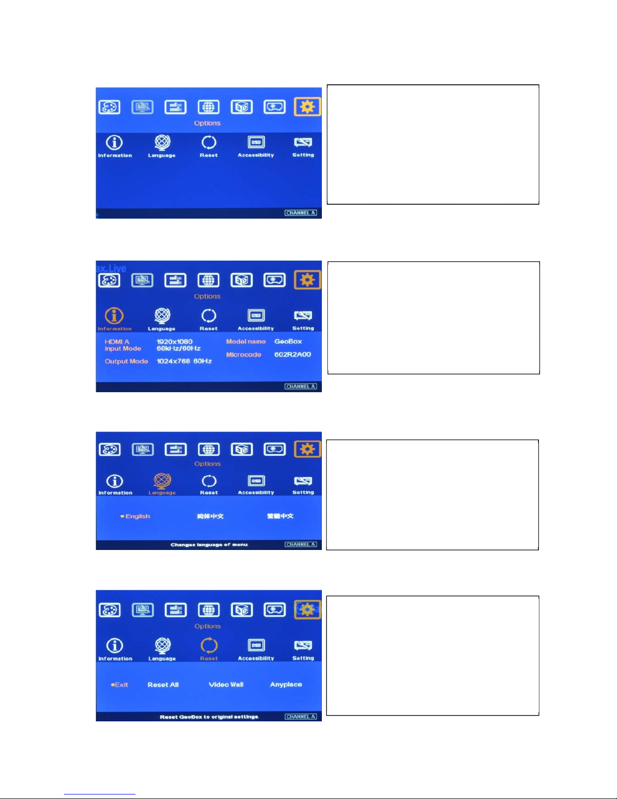
VWC-44
44
14 OSD Miscellaneous Functions—[Options]
14.1 System Information: [Information]
14.2 OSD Language: [Language]
14.3 [Reset]
[Exit] menu will exit from [Reset] menu and the system settings will not be changed.
[Reset All] menu will reset AV-BOX to its factory default settings but the setting stored in [Profile] &
Act
ivate [Options] Menu by Front Panel keypad
or Remote Controller.
In [Information] menu, it will show the
information in AV-BOX, such as output
mode, input mode, Model name and
Microcode version.
In [Reset] menu, three types of Reset can be
d
one: Reset All, reset Video Wall and reset
[Anyplace] function.
In [Language] menu, three languages can be
s
elected as OSD Language:
English, Simplified Chinese and Traditional
Chinese
Page 46
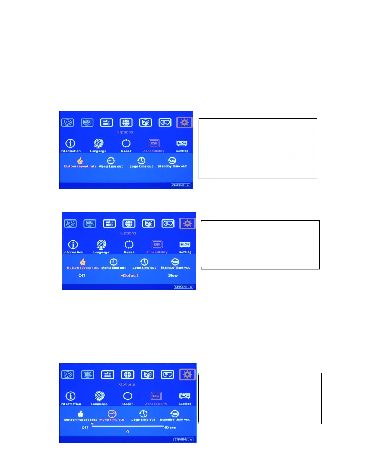
VWC-44
45
[Gwarp] will be kept the same without change.
[Video Wall] menu will reset the settings in Video Wall function to its factory default settings but all
other settings will remain the same without change.
[Anyplace] menu will reset the settings in [Anyplace] function to its factory default settings but all
other settings will remain the same without change.
14.4 [Accessibility]
14.4.1 [Button Repeat Rate]
OSD [Button Repeat Rate]:
[Off]: OSD only responds once when every time OSD key is pressed.
[Default]: OSD will respond slowly at the beginning but will increase the speed of the response
when OSD key is pressed continuously.
[Slow]: OSD behavior is similar to [Default] but the response speed will be slower than Default.
14.4.2 [Menu Time Out]
In [Accessibility] menu, four items can be
set:
OSD [Button Repeat Rate], OSD [Menu
Time out]、[Logo Time Out] and [standby
time out]
OSD [Button Repeat Rate]:
It controls the speed of the response of the
OSD button while user presses OSD button
continuously.
OSD [Menu Time Out]
OSD menu will disappear from the screen
based on time setting.
The default time is 30 seconds.
Page 47
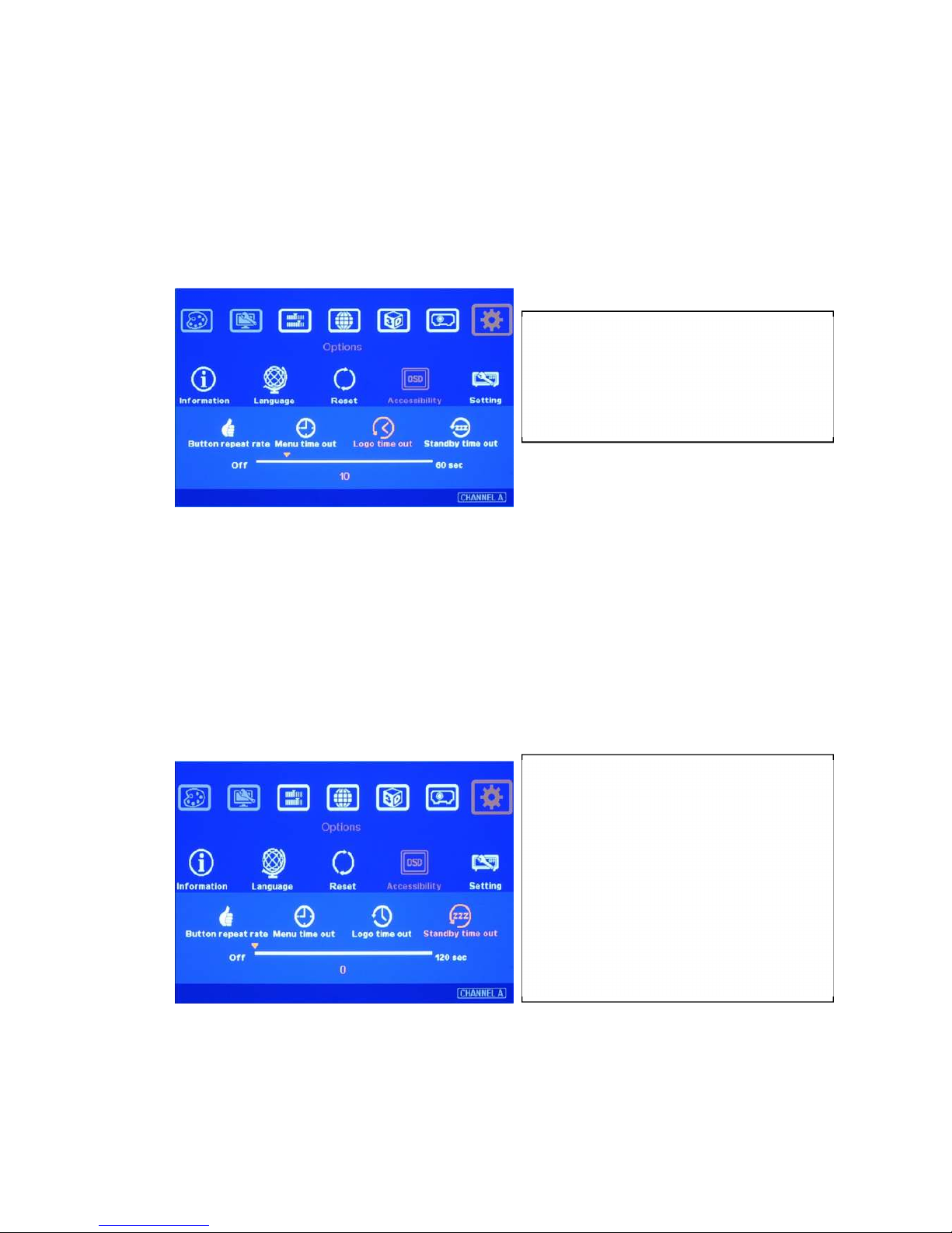
VWC-44
46
When [Off] is selected, the OSD menu will remain in the screen until user activates other OSD
function.
Internal Grid Pattern will be also controlled by the time setting in [Menu Time Out] menu. For
[Anyplace] geometry adjustment, we recommend user to set OSD [Menu Time Out] to [Off] to
maintain continuously display of the pattern and OSD on the screen.
14.4.3 [Logo Time Out]
Before the time out of the Splash screen, AV-BOX will not execute other commands in the system.
When the input is VGA, if any geometry adjustment occurred, the image position may change due to
projector auto adjustment function. In this case, user can disable projector auto alignment or to set
longer Logo Time Out so that AV-BOX will not execute geometry adjustment before projector
finishes auto alignment. A good match in the system power ON procedure and Logo time out will
maintain the image position while user powers ON/OFF the complete system.
14.4.4 [Standby Time Out]—system power ON/OFF control by input signal
This function is to Power ON/OFF complete system through signal source.
14.5 [Setting]
To set the time to show Splash screen.
If zero is selected, then the splash screen
will not be showed during system booting
up period.
If it is set to “60”, VWC-44 will
automatically Power off when no input
signal is detected for 60 seconds. In this
case, the output signal to projector will
be shut down as well.
If the projector can also automatically
shut down when no input signal is
detected. User only needs to control
signal source to turn ON/OFF the system.
Page 48
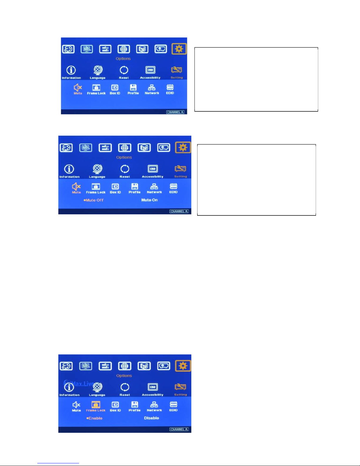
VWC-44
47
14.5.1 Audio [Mute]
14.5.2 Frame Lock and Smooth Switching Mode
[Frame Lock] will ensure the input and output frame rate synchronize together. When the application
uses multiple AV-BOX, the signal in each AV-BOX will also have better synchronization without frame
tear. However, when the input timing change or video source have been changed, the output signal will
be broken for short time temporarily and it will cause display devices to re-search input source and no
video image will be displayed during that time. If user wants to eliminate this kind of waiting time, user
can
[Disable] frame lock to maintain continuous output in AV-BOX while input source or timing changes. This
kind of Smooth Switching Mode is only available when the signal change is in same vertical frequency,
such as within NTSC or Pal. If the input timing change is between NTSC or PAL, there will be still
temporary signal break and the display devices will re-synchronize the input signal again. When Frame
Lock is [Disable], AV-BOX will shorten the time for mode change. The system will also conduct HDCP
verification. This verification process will also take some time. Therefore the time for mode change may
be different in different cases.
There are 4 items under [Settings] menu:
[
Mute] Audi mute or enable
[Box ID]: Set control ID
[Profile]: Save profile settings
[Network]: set RS232 and network control
Audio Mute:
[
Mute Off] will enable audio output.
[Mute On] will disable audio output.
[Mute] hot key in remote controller is
available
Page 49
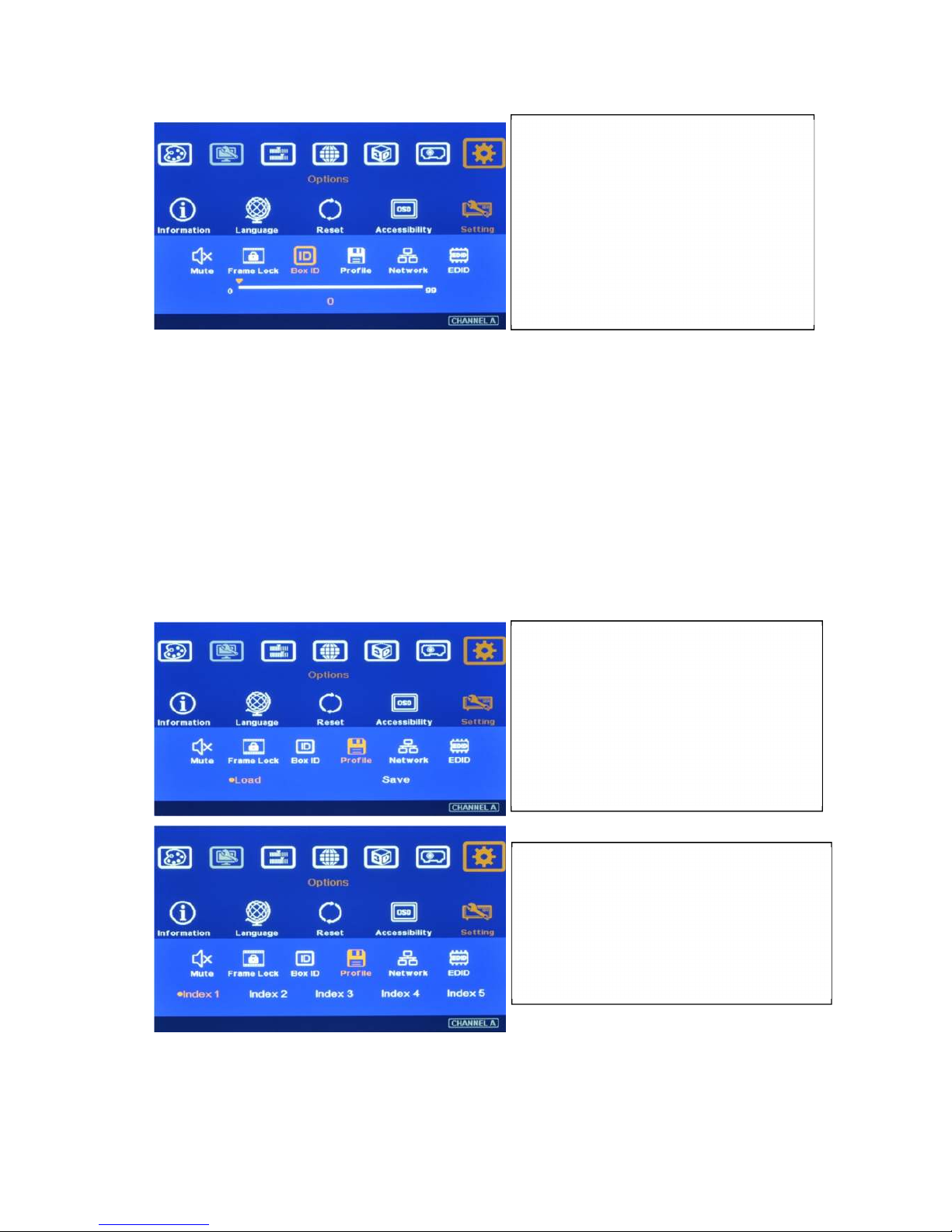
VWC-44
48
14.5.3 [Box ID]
Press number keys in Remote Controller for the control of multiple AV-BOX:
850: simultaneous control for all AV-BOX
851: control AV-BOX ID No. 1
853: control AV-BOX ID No. 3
A flashing LED indicator is to show the AV-BOX that has been locked without action.
Note: “85+ID” function is only functional when all AV-BOX IR receivers are put together. When user
presses “851”, then all the AV-BOX except ID No. 1 will be locked with flashing LED on the
front panel. User can only control ID No. 1 AV-BOX in this case. If IR receivers are set in
different location, then “85+ID” setting is not necessary.
14.5.4 [Profile Setting]
User can use profile setting function to show different display styles in the applications. If you have 4x1
display setup,
1. User can implement:
Switching among different input ports.
4 projector edge blending as one seamless screen
[Box ID] is the identification No of
each AV-BOX
AV-BOX ID No is from 1-99
After set Box ID, user can control
AV-BOX individually via IR Remote
controller, RS232 & Ethernet
User can use “85+ID” key on remote
controller to control each AV-BOX.
[Profile] is to save and load AV-BOX
settings including input port, output
resolution and all the settings in AV-BOX
When reset the system or FW update, the
settings saved in [Profile] will remain the
same without change.
Five Indexes can be chosen to save AV-BOX
settings in each AV-BOX and can be
reloaded by IR remote controller, RS232 or
Ethernet through [Load] menu under [Profile]
Page 50
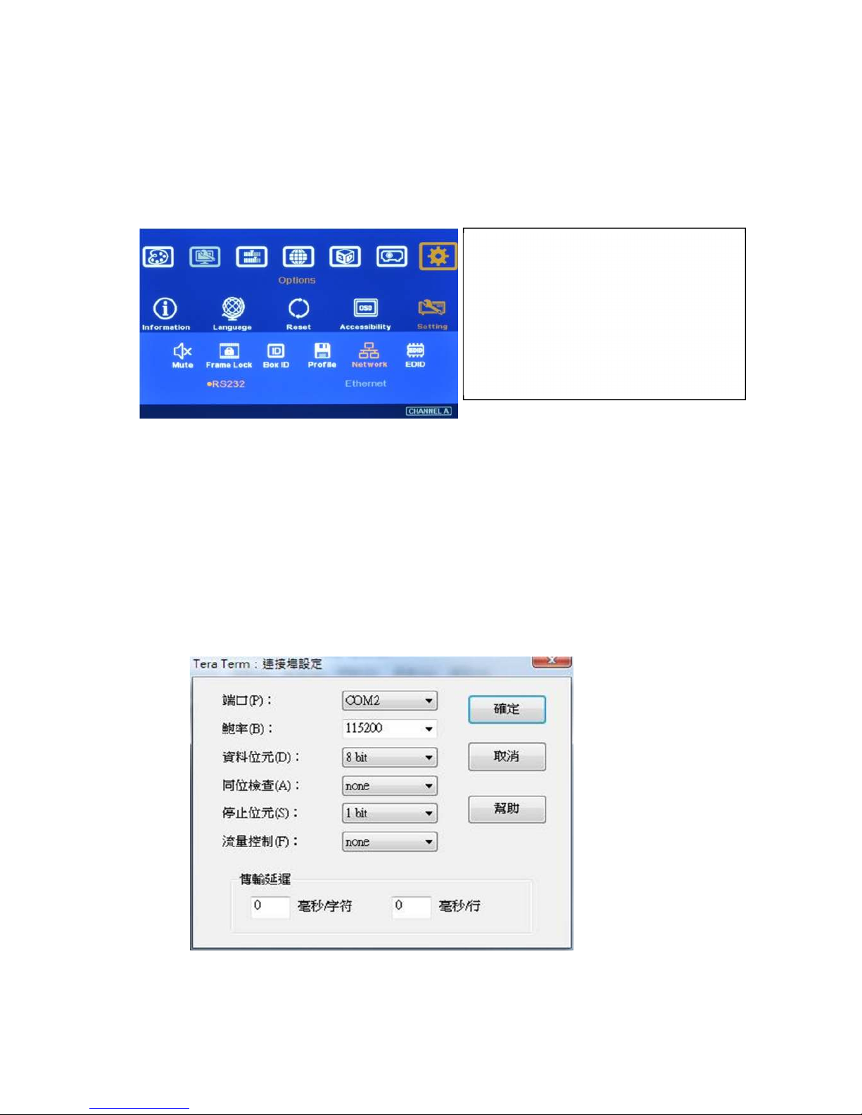
VWC-44
49
Two different contents displayed in 2+2 display modes.
Two different contents displayed in 2+1 display modes.
2. User can switch among different display styles (profiles) within seconds through IR remote controller,
RS232 or Ethernet
14.5.5 [Network]
14.5.5.1 [RS232] Command
RS232 interface is designed with DB-9 connector. The UART Protocol between AV-BOX and
a Host computer can be provided. The protocol can be implemented via RS-232, USB,
Ethernet or other forthcoming communication methods.
Detailed RS-232 protocol can be provided as needed.
14.5.5.1.1 RS232 setting
a、、、、 Serial port setup
b、、、、 Terminal setup
Two choices under [Network] menu:
RS232 & Ethernet
User can only select one control method
between RS232 and Ethernet.
If no addition Ethernet module in AV-
BOX, only RS232 can be selected.
Page 51
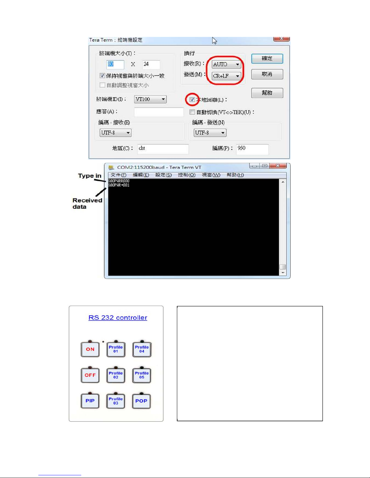
VWC-44
50
15.5.5.1.2 Example of low cost RS232 controller
14.5.5.2 [Ethernet] control
Ethernet control: AV-BOX is design with optional [Ethernet] control interface through RJ45
User can save up to 5 settings into [Profile].
User can connect this RS232 controller with each
VWC-44 through RS232 cable in parallel.
Click Profile button in RS232 controller to power
on/off the system or select display Profile.
If separate RS232 control is required, user needs to
set different [Box ID] for each VWC-44 and put ID #
into RS232 command.
Page 52
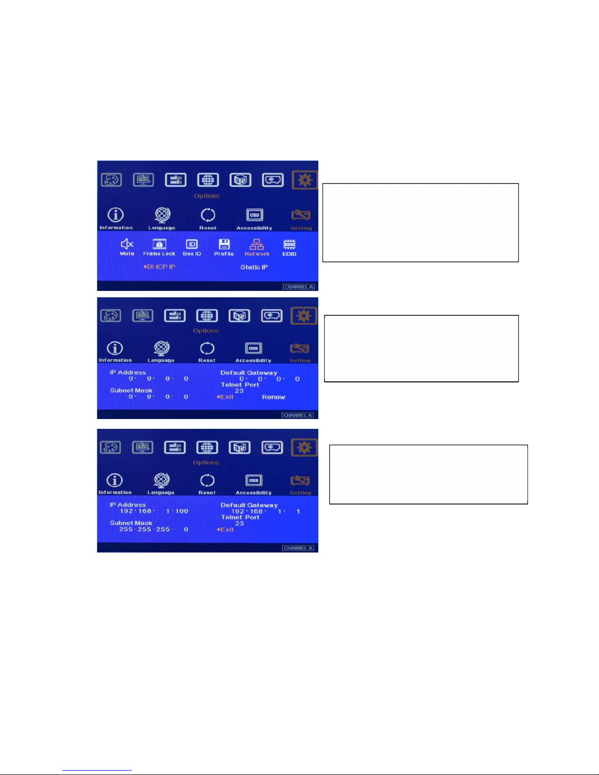
VWC-44
51
connector. User can controller AV-BOX through Ethernet or WiFi via PC or mobile devices, such
as Smart Phone, iPhone and iPad. A webpage with keypad icons (virtual keypad) will be showed
in control devices for user to control all the OSD function of AV-BOX.
Additional built-in Ethernet Module is required.
User can use external Ethernet to RS232 conversion box to control AV-BOX through Ethernet.
User can use < > OSD direction keys to access the position for the modification and ˄ ˅ OSD
direction keys to change the value in the IP settings.
Ethernet Webpage (Virtual keypad in the screen):
If Ethernet Router supports PnP protocol, user can see AV-BOX device in the network. After
connection, it will show below content in the webpage. It includes virtual keys for the operation of
the OSD menu.
If user has Ethernet connection problem, please power ON/OFF AV-BOX or WiFi router again.
In [Ethernet] menu, there are two
a
lternatives:
DHCP IP & Static IP
DHCP IP is assigned by Ethernet router or
Et
hernet switch hub.
Static IP can be programmed through OSD
ke
ypad or remote controller.
Page 53
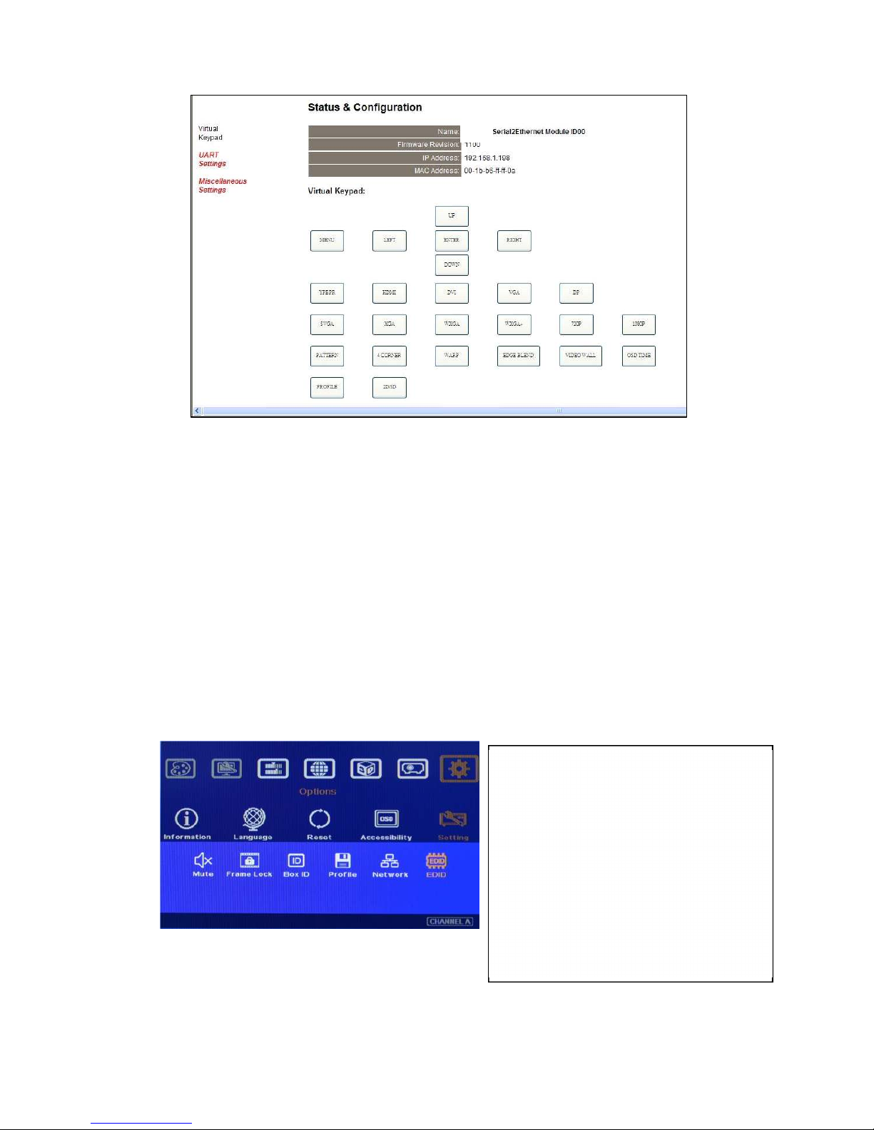
VWC-44
52
AV-BOX
14.5.6 [EDID] setting
a、 Selective EDID setting is added into AV-BOX. The purpose are as follows:
AV-BOX can support big range of input signal timing—from SVGA up to 4k/2k. In order to get
the best video performance, user needs to select different input signal resolution.
Different PC display cards have different setting and behavier. Many users may not be able to do
the right settings
High end media player or server can support big range of outputs—from 720p to 4k/2k. If no
EDID selection function, only one default EDID can be selected by media player. The system
may not show the best video quality.
Different display modes may show different final image aspect ratio. User can ultilize different
EDID setting to change input signal timing and get different output aspect ratio.
Act
ivate EDID setting menu:
[Options] [Setting] [EDID]
Use IR remote controller to select desired
EDID.
After select EDID, the PC or medial will
automatically change the output timing
setting.
Press [INFO] key to check if the input and
output timing are set correctly.
Page 54
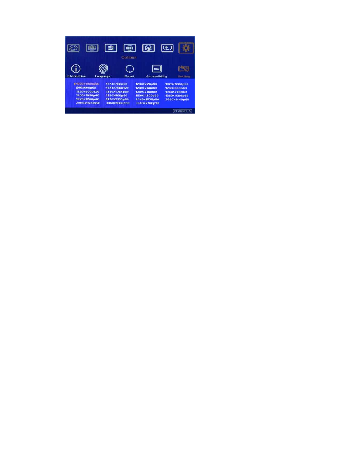
VWC-44
53
b、 In very rare cases, some PC may not detect the right EDID from AV-BOX and show different result.
If it happens, please open resolution setting window and select desired output resolution and set
display aspect ratio from PC.
c、
User can also set non-VESA standard output timings from PC, AV-BOX can accept this kind of
output timing
under the conditions that the maximum clock rate shall be under 300MHz and the
resolution shall not exceed 4096x2160.
15 .Screen Selection
a. Gain value less than 1.5 will be recommended for Edge Blending application. Higher gain value will
be more sensitive to color difference among different projectors. In short throw projector edge
blending, viewer may see different edge blending result while viewing at different angles.
b. Motorized screen position may be shifted from time to time. It will affect the image stacking in edge
blending area and may cause blurred image. Fixed screen is recommended.
16 .Projector Selection and settings
a. The projectors for the edge blending should be the same model and the same production lot. If they
are not the same models, it may create some difficulty and performance issue.
b. Usually, higher contrast ratio in the projector will have better black level performance. The projector
with contrast ration more than 3000:1 is recommended for multiple projector edge blending. In a dark
environment, video projector with 10,000:1 contrast ration or higher will be better. This contrast ratio
should be native contrast ratio but not dynamic contrast ratio.
c
. Most of DLP projector will provide a function for 3D color adjustment to fine-tune R, G, B, Y, C, M six
colors. It will help the color fine tune in multiple images from different projectors.
d. All the projectors shall have the same setting—including optical zoom ratio, color temperature, color
characteristics, lamp setting, display mode...etc.
e. Most projectors have different display mode for different applications, such as Presentation, Video,
sRGB and User mode. Different display modes have different gamma settings and affect the video
quality in overlap region. User needs to try with different display modes to get optimized image
f. The mechanical stability in optical system will be important. It should be rigid with less thermal drift. A
projector with big ZOOM and lens shift will be more convenient for the installation
Page 55
VWC-44
54
17 S
pecifications:
VWC-44
Video input/output
ports
1. Input:
a、 1x DualLink DVI-I
b、 2x HDMI 1.4 input
c、 1x DisplayPort 1.1a input
d、 1x VGA port supports (Up to 205MHz input timing)
e、 All digital input ports support 3840x2160 @30Hz, 2560x1600 and 3840x1080
at 60Hz
2. Output:
a、 2x HDMI outputs for RH/LH channel up to 1920x1200 @60Hz
b、 1x HDMI loop out port from HDMI-A input for daisy chain connection up to
3840x2160 @30Hz
c、 Compliant with HDCP 1.3 High-bandwidth Digital Content Protection
Image geometry
correction, warp and
Edge Blending
(Anyplace function)
1. With full functions for 4 corner alignment, vertical and horizontal keystone
correction, Pincushion & Barrel adjustment, image warp and image 180〫 flip.
2.
Each unit controls dual projectors and can be expanded with multiple VWC-44
to support unlimited number of projectors.
3. Full function front panel keypads and IR remote controller. Manual geometry
alignment up to 5*3 grid patterns.
4.
Gwarp PC Tool is available for warp and geometry alignment up to 17x17 grid
pattern. After finishing geometry alignment, the parameters can be stored inside
VWC-44 and no more PC is needed.
5. Execute 4 directions edge blending. No limitation in the number of edge blending.
6. Provide complete function for edge blending fine-tune and color correction.
7. Precise black level uplift to compensate light leakage in the projector.
8. White balance and grey level adjustment for each projector.
9. One PC tool can control dual processing channels simultaneously.
10. Able to perform flat & curved screen seamless edge blending, including irregular
curved screen and 360 degrees curved screen.
Video Wall
1. Magnify, scroll & pan through all inputs.
2. Image split, cropping and assign display location.
3. Pixel based overlap adjustment in all edges, up to 15x15 matrix displays.
4. Overlap pixel adjustments up to 900 pixels for image position shift, bezel
compensation and creating overlap region for edge blending.
5. Connect with 4k/2k input signal and split the image for display devices without
additional PC, image splitter or other devices.
6. Serve as video wall controller for irregular video wall display up to 15x15 matrix
display from single signal input source.
High end video
processing and
de-interlace
1. 3D motion adaptive de-interlace for main and PIP images
2. Low angle edge smooth algorithm (similar to Faroudja® DCDi)
3. Automatic 3:2 and 2:2 pull-down film mode detection and recovery
4. True 10-bit data processing
3D stereoscopic
display
1. Auto decode 3D signals for passive 3D display, including signal source from Blue
Ray, STB, game console, media player and PC.
2.
Auto decode Stereoscopic Player/ Nvidia 3D Vision 1080p @120Hz 3D format and
Blue Ray 1080p 24Hz 3D signal into 720p/XGA 120Hz signal for active 3D display.
3. Support standard HDMI 1.4a 3D format, including 1080p/24Hz full HD, Side by
Side, Top-Bottom & Line interleaved.
Page 56
VWC-44
55
4. Support 3840x1080 Full HD Side by side 3D format and SONY 1080i/60Hz frame
packed 3D.
5. “Perfect Sync” algorithm for Zero latency in RH/LH eye image to get the most
comfortable 3D.
6. Precise geometry stacking alignment and allow 2D/3D in the same setup with
clear image and OSD menu.
7.
3Ddisplay can be on flat and curved screen. It can be expanded by more projector
image stacking or edge blending.
Aspect ratio
1. Full screen or maintain input signal original aspect ratio.
2. Switch between 2.35:1 & 16:9 aspect ratio
3. Other aspect ratio can be changed by EDID setting and through Video Wall and
Geometry adjustment function.
System control and
convenient features
for system
integrators
1. Reliable and durable design for long term industrial and commercial applications.
2. Able to use low cost projector, no lens shift, warping or edge blend function are
required
3. Full functional keypads & IR control.
4.
ID # for each AV-BOX. Convenient for system installation and control through
IR, RS232 and Ethernet.
5.
Gwarp PC tool is available to control VWC-44 through USB.
6. keypad Lock (press menu for 5 seconds) to avoid setting loss due to negligence.
7. Up to 5 profile settings for flexible display modes memory and recall.
8. Integrated with IR extender (up to 20 meters), RS-232 and optional Ethernet
control.
9. Automatic power ON/OFF through input signal control.
Power supply
1. External DC 12V/3A power supply
2. Auto low power standby mode
Weight
2.35 Kg (AV-BOX body only)
Dimensions
440mmL x 190mmD x 44mmH
Page 57
VWC-44
56
18 Revision History
Revision Date Originator Comments
V 1.01 2015-10-31 Steve Wang First revision
V 1.02 2015-11-24 Steve Wang Update PC tool application
V1.03 2015-12-07 Steve Wang Add color fine tune in edge blending region
V2.01 2015-12-26 Steve Wang Content review and modifications.
V2.02 2015-01-26 Steve Wang Add [Corner Shift] in Gwarp
V2.03 2015-02-26 Steve Wang Modify [Anyplace] manual
V2.04 2015-03-07 Steve Wang Modified wording and typo
 Loading...