

Page 1

Avaya
User’s Guide
AVAYA™ X330WAN
MULTISERVICE WAN ACCESS ROUTER MODULE
SOFTWARE VERSION 3.12
September 2002
Page 2

Page 3

Contents
List of Tables............................................................................................................. xiii
List of Figures.............................................................................................................. xv
Preface ............................................................................................................................ I
About This Guide...................................................................................................I
Objectives .......................................................................................................I
Audience .........................................................................................................I
Conventions ...................................................................................................I
Naming ...................................................................................................I
Notes, Cautions and Warnings ...........................................................I
CLI Commands .................................................................................... II
Documentation Accuracy ........................................................................... II
General System Information................................................................................II
Preventing Toll Fraud ................................................................................. II
Important Safety Information ...................................................................III
Chapter 1 Introduction................................................................................................................... 1
Overview ................................................................................................................ 1
Features................................................................................................................... 2
Layer 1 Features ............................................................................................ 2
X330W-2DS1 ..........................................................................................2
X330W-2USP ......................................................................................... 2
Layer 2 Features ............................................................................................ 2
Layer 3 Features ............................................................................................ 3
Convergence Features ................................................................................. 3
Sample Applications............................................................................................. 4
Branch Office Connectivity to Headquarters ........................................... 4
Small/Medium Business Connectivity Directly to a Service Provider 5
Functional Concepts Overview........................................................................... 5
WAN Access .................................................................................................5
Routing ..........................................................................................................5
Security ..........................................................................................................6
Convergence .................................................................................................6
Avaya X330WAN Network Management.........................................................6
Command Line Interface (CLI) .................................................................. 6
Avaya P330 Device Manager (Embedded Web) ......................................7
Multiservice Network Manager (MSNM) ................................................ 7
Avaya X330WAN User’s Guide i
Page 4

Contents
Requirements and Specifications ........................................................................7
Environmental Specifications .....................................................................7
Power & Heat Dissipation ...........................................................................8
Chapter 2 Installation..................................................................................................................... 9
Installation Safety Information............................................................................9
P330 Software Support for X330WAN .............................................................10
Installing an X330WAN Module into an Avaya P330 Switch.......................10
Power On Self Test .....................................................................................11
X330W-2DS1 Front Panel and LEDs.................................................................12
X330W-2USP Front Panel and LEDs.................................................................13
Avaya P330 LEDs ................................................................................................14
Connecting the X330WAN.................................................................................15
Connecting the E1/T1 WAN Ports ..........................................................15
Connecting the USP Ports .........................................................................15
Connecting the Fast Ethernet (10/100Base-T) Port ...............................15
Connecting the Console Port ....................................................................15
Removing an X330WAN Module from an Avaya P330 Switch ...................16
Chapter 3 Initial Configuration.................................................................................................. 17
Configuring the X330WAN................................................................................17
Establishing a Console Connection ..........................................................17
Establishing a Modem Connection ..........................................................18
Checking the Modem Configuration ...............................................19
Establishing a Telnet Connection .............................................................19
Configuring Loopback Interfaces .............................................................20
Configuring Fast Ethernet Interfaces .......................................................20
Configuring the FabricFast Ethernet Interface .......................................21
Configuring E1/T1 Interfaces ...................................................................22
Configuring USP Interfaces .......................................................................25
Checking the Loopback, Fast Ethernet, E1/T1/USP, IP Interface Config-
uration ........................................................................................................27
Saving Your Configuration .......................................................................28
X330WAN Default Settings................................................................................28
Chapter 4 Operational Concepts and Configuration Examples........................................... 31
Detailed Interface Concepts ...............................................................................31
Physical Interfaces ......................................................................................31
Layer 2 Virtual Interfaces ..........................................................................32
Enhanced Routing Capabilities .........................................................................35
Static Route Configuration ........................................................................35
“via interface” Static Route ...............................................................36
Permanent Static Route ......................................................................36
Discard Route ......................................................................................37
ii Avaya X330WAN User’s Guide
Page 5

Contents
Export Default Metric ................................................................................37
OSPF Dynamic Cost Support ................................................................... 37
RIP Distribution Access Lists ...................................................................38
Fragmentation and Reassembly ...............................................................39
Configuring X330WAN to Connect Branch Offices to Headquarters 39
Configuration Example for Branch Office 1 ...................................41
Configuration Example for Branch Office 2 ...................................42
Configuring the X330WAN for use with an External Firewall ...........43
Backup Interfaces ................................................................................................44
Frame Relay Encapsulation ............................................................................... 46
Priority DLCI ..............................................................................................46
Traffic Shaping and Marking ...................................................................47
Priority Queuing ......................................................................................... 48
Policy..................................................................................................................... 48
Controlling Network Access to the X330WAN .....................................52
RTP Header Compression (cRTP) ....................................................................53
QoS and VoIP Treatment ................................................................................... 55
QoS Implementation for PPP Encapsulation .........................................55
Data Mode ...........................................................................................56
VoIP Mode ...........................................................................................57
VoIP Implementation with a G700 Media Gateway and an S8300 Media
Server .................................................................................................................. 58
PPP VoIP Configuration ............................................................................ 58
Configuration Example for Site A ....................................................60
Configuration Example for Site B .................................................... 61
Frame Relay VoIP Configuration ............................................................. 63
Scenario 1 - Traffic Shaping .............................................................. 63
Scenario 2 - Priority DLCI and Traffic Shaping .............................68
VoIP Implementation with DEFINITY (CLAN and Prowler) ...................... 73
Configuration Example for Site A ....................................................74
Configuration Example for Site B .................................................... 76
Chapter 5 Troubleshooting......................................................................................................... 79
Monitoring Traffic............................................................................................... 79
Handling E1/T1 Alarms .................................................................................... 80
LOS ...............................................................................................................81
LOF/Red .....................................................................................................81
High BER/Major ........................................................................................82
RAI/Yellow .................................................................................................82
AIS/Blue ......................................................................................................82
Troubleshooting X330W-2USP.......................................................................... 83
Using Loopbacks .................................................................................................83
Avaya X330WAN User’s Guide iii
Page 6

Contents
Chapter 6 X330WAN CLI Commands ....................................................................................... 87
Introduction: About the CLI ..............................................................................87
X330WAN CLI Prompts ............................................................................88
General: Device Commands ..............................................................................89
banner login .................................................................................................89
banner post-login ........................................................................................89
clear screen ..................................................................................................90
clear snmp trap ...........................................................................................90
clear timezone .............................................................................................90
copy running-config startup-config .........................................................90
copy running-config tftp ...........................................................................91
copy startup-config tftp .............................................................................91
copy tftp startup-config .............................................................................92
copy tftp EW_archive .................................................................................92
copy tftp SW_image ...................................................................................93
dir .................................................................................................................93
ds-mode ........................................................................................................95
erase startup-config ....................................................................................96
get time .........................................................................................................96
hostname ......................................................................................................96
line (Banner login/post-login context) ....................................................97
nvram initialize ...........................................................................................97
reset ..............................................................................................................98
set boot bank ................................................................................................98
set logout ......................................................................................................99
set snmp trap ...............................................................................................99
set snmp trap auth ....................................................................................100
set snmp trap enable frame-relay ...........................................................100
set snmp trap disable frame-relay ..........................................................101
set system contact .....................................................................................101
set system location ....................................................................................101
set system name ........................................................................................102
set time client .............................................................................................102
set time protocol .......................................................................................102
set time server ...........................................................................................103
set timezone ...............................................................................................103
show banner login ....................................................................................103
show banner post-login ...........................................................................104
show boot bank .........................................................................................104
show copy status .......................................................................................104
show dev log file .......................................................................................105
show erase status ......................................................................................105
show image version ..................................................................................105
show logout ...............................................................................................105
iv Avaya X330WAN User’s Guide
Page 7

Contents
show module-identity ............................................................................. 106
show running-config ................................................................................ 106
show snmp ................................................................................................ 106
show startup-config .................................................................................107
show system .............................................................................................. 107
show tftp download software status ..................................................... 107
show tftp download/upload status ......................................................108
show time ..................................................................................................108
show time parameters .............................................................................108
show timezone .......................................................................................... 109
sync time ....................................................................................................109
tech ............................................................................................................109
terminal length .......................................................................................... 109
terminal width ..........................................................................................110
Console (RS232) Interface CLI Commands ...................................................110
async mode interactive (Console interface context) ............................110
async mode terminal (Console interface context) ................................ 110
async reset-modem (Console interface context) ..................................110
interface Console ......................................................................................111
ppp authentication (Console interface context) ...................................111
speed (Console context) ...........................................................................111
timeout absolute (Console interface context) .......................................112
Fast Ethernet Interface CLI Commands......................................................... 112
autoneg (FastEthernet interface context) .............................................. 112
duplex (FastEthernet interface context) ................................................ 113
interface FastEthernet ..............................................................................113
speed (FastEthernet interface context) .................................................. 114
FabricFast Ethernet Interface CLI Commands..............................................114
interface FabricFastEthernet ...................................................................114
Controller CLI Commands (X330WAN-2DS1 Only) ...................................115
cablelength long (Controller context) .................................................... 115
cablelength short (Controller context) ...................................................116
channel-group (Controller context) .......................................................117
clear controller counters (X330WAN-2DS1) .........................................118
clock source (Controller context) ...........................................................118
controller ....................................................................................................119
description (Controller context) ............................................................. 120
fdl ................................................................................................................120
framing (X330WAN-2DS1 Controller context) ....................................121
idle-character (X330WAN-2DS1 Controller context) ..........................121
linecode (Controller context) .................................................................. 122
loopback diag (Controller context) ........................................................ 123
loopback local (Controller context) ........................................................123
loopback remote (Controller context) ...................................................124
Avaya X330WAN User’s Guide v
Page 8

Contents
no channel group (Controller context) ..................................................124
no loopback (Controller context) ............................................................124
remote (Controller context) .....................................................................125
show controllers ........................................................................................125
show controllers remote ..........................................................................129
shutdown (Controller context) ...............................................................129
Interface Serial CLI Commands ......................................................................129
backup delay (Serial interface context) ..................................................129
backup interface (Serial interface context) ............................................130
clear ip rtp header-compression .............................................................130
clear ip tcp header-compression (PPP interface) .................................131
description (X330WAN-2USP Serial interface context) ......................131
idle-character (X330WAN-2USP Serial interface context) ..................131
ignore-dcd (X330WAN-2USP Serial interface context) .......................132
interface Serial (X330WAN-2DS1) ..........................................................132
interface Serial (X330WAN-2USP) .........................................................133
invert txclock (X330WAN-2USP) ...........................................................134
load-interval (Serial interface context) ..................................................134
loopback (X330WAN-2USP Serial interface context) ..........................134
mtu (Serial interface context) ..................................................................135
nrzi-encoding (X330WAN-2USP Serial interface context) .................135
queue-limit (Serial interface context) .....................................................135
show ip rtp header-compression ............................................................136
show ip rtp header-compression brief ...................................................137
show ip tcp header-compression ............................................................137
show ip tcp header-compression brief ..................................................138
show queueing ..........................................................................................139
shutdown (X330WAN-2USP Serial interface context) ........................139
transmitter-delay (X330WAN-2USP Serial interface context) ...........139
voip-queue (Serial interface context) .....................................................140
Frame Relay Configuration CLI Commands.................................................140
bc out (Map-class context) .......................................................................140
be out (Map-class context) .......................................................................140
cir out (Map-class context) ......................................................................141
clear frame-relay counters .......................................................................141
de-buffer-size (Frame Relay Serial interface context) ..........................141
de pre-mark (Map-class context) ............................................................142
encapsulation frame-relay (Serial interface context) ...........................142
fragment (Map-class context) .................................................................143
frame-relay class-dlci (Serial sub-interface context) ............................143
frame-relay interface-dlci (Serial sub-interface context) .....................143
frame-relay lmi-type (Serial interface context) .....................................144
frame-relay lmi-n391dte (Serial interface context) ...............................144
frame-relay lmi-n392dte (Serial interface context) ...............................145
vi Avaya X330WAN User’s Guide
Page 9

Contents
frame-relay lmi-n393dte (Serial interface context) ..............................145
frame-relay priority-dlci-group (Serial sub-interface context) .......... 145
frame-relay traffic-shaping (Serial interface context) .........................146
keepalive (Serial interface context Frame Relay encapsulation) ....... 146
map-class frame-relay ..............................................................................147
show frame-relay fragment .................................................................... 147
show frame-relay lmi ............................................................................... 148
show frame-relay map .............................................................................149
show frame-relay pvc ..............................................................................150
show frame-relay pvc brief ..................................................................... 150
show frame-relay traffic .......................................................................... 150
show map-class frame-relay ................................................................... 151
PPP Configuration CLI Commands ............................................................... 151
ip tcp decompression-connections (PPP interfaces) ............................151
keepalive (Serial interface context PPP encapsulation) ...................... 151
ppp timeout ncp (Serial interface context) ...........................................152
ppp timeout retry (Serial interface context) .........................................152
Loopback CLI Commands ............................................................................... 153
interface Loopback ...................................................................................153
General Layer 2 Interface CLI Commands.................................................... 153
bandwidth (X330WAN-2USP Interface context) ................................. 153
clear counters ............................................................................................ 154
default-metric (Interface context) ...........................................................154
show interfaces ......................................................................................... 154
snmp trap link-status (Serial and Fast Ethernet interface contexts) .163
Layer 3 CLI Commands ................................................................................... 164
arp ..............................................................................................................164
arp timeout ................................................................................................164
clear arp-cache ..........................................................................................165
clear fragment ........................................................................................... 165
clear ip route .............................................................................................166
clear ip traffic ............................................................................................166
default-metric (Interface context) ...........................................................166
default-metric (Router-OSPF context) ...................................................167
default-metric (Router-RIP Mode) .........................................................167
distribution-list (Router-RIP Mode) ......................................................167
fragment chain ..........................................................................................168
fragment size .............................................................................................169
fragment timeout ......................................................................................169
ip address ..................................................................................................170
ip admin-state (Interface context) ..........................................................170
ip bootp-dhcp network (Interface context) ...........................................170
ip bootp-dhcp relay ..................................................................................171
ip bootp-dhcp server (Interface context) ............................................... 171
Avaya X330WAN User’s Guide vii
Page 10

Contents
ip broadcast-address (Interface context) ...............................................172
ip default-gateway ....................................................................................172
ip directed-broadcast (Interface context) ..............................................173
ip distribution access-default-action ......................................................173
ip distribution access-list .........................................................................174
ip distribution access-list-cookie ............................................................174
ip distribution access-list-copy ...............................................................175
ip distribution access-list-name ..............................................................175
ip distribution access-list-owner ............................................................176
ip icmp-errors ............................................................................................176
ip max-arp-entries ....................................................................................176
ip max-route-entries .................................................................................177
ip netbios-rebroadcast (Interface context) .............................................177
ip netmask-format ....................................................................................178
ip ospf authentication-key (Interface context) ......................................179
ip ospf cost (Interface context) ................................................................179
ip ospf dead-interval (Interface context) ...............................................180
ip ospf hello-interval (Interface Mode) ..................................................180
ip ospf priority (Interface Mode) ............................................................181
ip ospf router-id ........................................................................................181
ip proxy-arp (Interface context) ..............................................................181
ip redirects (Interface context) ................................................................182
ip rip authentication key (Interface context) ........................................182
ip rip authentication mode (Interface context) .....................................183
ip rip default-route-mode (Interface context) .......................................183
ip rip poison-reverse (Interface context) ...............................................184
ip rip rip-version (Interface context) ......................................................184
ip rip send-receive (Interface context) ...................................................185
ip rip split-horizon (Interface context) ...................................................185
ip route .......................................................................................................186
ip routing ...................................................................................................186
ip routing-mode (Interface context) .......................................................187
ip vrrp (Interface context) ........................................................................187
ip vrrp address ..........................................................................................188
ip vrrp auth-key ........................................................................................188
ip vrrp override addr owner ...................................................................189
ip vrrp preempt .........................................................................................189
ip vrrp primary .........................................................................................190
ip vrrp priority ..........................................................................................190
ip vrrp timer ..............................................................................................191
network (Router-OSPF context) .............................................................191
network (Router-RIP context) .................................................................192
no ip distribution access-list ....................................................................192
ping .............................................................................................................193
viii Avaya X330WAN User’s Guide
Page 11

Contents
redistribute (Router-OSPF context) .......................................................193
redistribute (Router-RIP context) ...........................................................194
router ospf ................................................................................................. 194
router rip .................................................................................................... 194
router vrrp ................................................................................................. 195
show fragment ..........................................................................................195
show ip arp ................................................................................................196
show ip distribution access-lists ............................................................ 196
show ip icmp .............................................................................................197
show ip interface ......................................................................................197
show ip interface brief ............................................................................. 198
show ip ospf ..............................................................................................199
show ip ospf database ............................................................................. 199
show ip ospf interface ..............................................................................200
show ip ospf neighbor ............................................................................. 201
show ip protocols .....................................................................................201
show ip reverse-arp ................................................................................. 202
show ip route ............................................................................................203
show ip route best-match ........................................................................203
show ip route static ..................................................................................204
show ip route summary ..........................................................................204
show ip traffic ........................................................................................... 205
show ip vrrp .............................................................................................. 206
show ip vrrp detail ................................................................................... 207
timers basic (Router-RIP context) ..........................................................208
timers spf (Router-OSPF context) ..........................................................208
traceroute ................................................................................................... 209
Policy CLI Commands...................................................................................... 209
ip access-default-action ...........................................................................209
ip access-group (Interface context) ........................................................209
ip access-list ...............................................................................................210
ip access-list-cookie ..................................................................................211
ip access-list-copy .....................................................................................211
ip access-list-dscp name ..........................................................................212
ip access-list-dscp operation ...................................................................212
ip access-list-dscp precedence ................................................................ 212
ip access-list-dscp trust ............................................................................213
ip access-list-name ....................................................................................213
ip access-list-owner ..................................................................................214
ip composite-op access ............................................................................214
ip composite-op dscp ............................................................................... 215
ip composite-op name .............................................................................215
ip composite-op notify .............................................................................216
ip composite-op priority ..........................................................................216
Avaya X330WAN User’s Guide ix
Page 12

Contents
ip simulate (Interface context) ................................................................217
no ip composite-op ...................................................................................218
set qos policy-source ................................................................................218
show ip access-group ...............................................................................218
show ip access-list-dscp ...........................................................................219
show ip access-lists ...................................................................................219
show ip access-lists details ......................................................................220
show ip access-list-summary ..................................................................220
show ip active-access-groups ..................................................................221
show ip composite-op ..............................................................................221
validate-group (Interface context) ..........................................................221
Appendix A Interface Specifications........................................................................................... 223
DTE V.35 .............................................................................................................223
Introduction ...............................................................................................223
Pinouts ........................................................................................................223
DTE X.21 .............................................................................................................225
Introduction ...............................................................................................225
Pinouts ........................................................................................................225
Console Pin Assignments.................................................................................226
Appendix B Embedded Web Manager........................................................................................ 227
System Requirements........................................................................................227
Running the Embedded Manager...................................................................228
Installing the Java Plug-in................................................................................230
Installing from the Avaya P330 Documentation and Utilities CD ....231
Installing from the Avaya Site ................................................................231
Installing from your Local Web Site ......................................................231
Installing the On-Line Help and Java Plug-In on your Web Site...............231
Documentation and Online Help....................................................................232
Software Download...........................................................................................232
Appendix C Standards and Compliance..................................................................................... 233
ANSI Standards Compliance...........................................................................233
ITU-T Standards Compliance ..........................................................................233
RFC Standards Compliance .............................................................................234
NEBS Standards Compliance...........................................................................235
Type Approval Standards ................................................................................235
Safety Standards Compliance .................................................................236
Electromagnetic Standards Compliance (EMC) ...................................236
Telecommunication Standards Compliance .........................................237
x Avaya X330WAN User’s Guide
Page 13

Contents
Appendix D How to Contact Us ................................................................................................... 239
In the United States........................................................................................... 239
In the EMEA (Europe, Middle East, and Africa) Region............................. 239
In the AP (Asia Pacific) Region ....................................................................... 241
In the CALA (Caribbean and Latin America) Region ................................. 241
Avaya X330WAN User’s Guide xi
Page 14

Contents
xii Avaya X330WAN User’s Guide
Page 15

List of Tables
Table 2.1 X330W-2DS1 LED Descriptions ...............................................12
Table 2.2 X330W-2USP LED Descriptions............................................... 13
Table 3.1 X330W-2DS1 CLI Interface Contexts.......................................24
Table 3.2 X330W-2USP CLI Interface Contexts ......................................27
Table 3.3 X330W-2DS1 Default Settings ..................................................28
Table 3.4 X330W-2USP Default Settings .................................................. 29
Table 5.1 Alarms.......................................................................................... 80
Table 6.1 X330WAN-2DS1 CLI Prompts .................................................88
Table A.1 V.35 DCE Serial Cable Pinouts...............................................223
Table A.2 X.21 DCE Serial Cable Pinouts...............................................225
Table A.3 Pinout for Console Communications....................................226
Avaya X330WAN User’s Guide xiii
Page 16

List of Tables
xiv Avaya X330WAN User’s Guide
Page 17

List of Figures
Figure 1.1 X330W-2USP and X330W-2DS1 Modules................................. 2
Figure 2.1 X330W-2DS1 Front Panel .......................................................... 12
Figure 2.2 X330W-2USP Front Panel..........................................................13
Figure 2.3 Avaya P330 Front Panel LED Indicators ................................ 14
Figure 4.1 T1 Port with PPP Encapsulation..............................................33
Figure 4.2 E1/T1 Port with Frame Relay Encapsulation ........................33
Figure 4.3 USP Port with Frame Relay Encapsulation............................33
Figure 4.4 USP Port with PPP Encapsulation........................................... 34
Figure 4.5 Connecting Branch Offices to Headquarters..........................40
Figure 4.6 X330WAN with Security ........................................................... 43
Figure 4.7 Default Composite Operations Table......................................49
Figure 4.8 QoS Queues................................................................................. 55
Figure 4.9 Default QoS Behavior ................................................................57
Figure 4.10 PPP VoIP Configuration............................................................58
Figure 4.11 VoIP Configuration with Frame Relay Encapsulation ......... 63
Figure 4.12 PPP VoIP Configuration with DEFINITY............................... 73
Figure 5.1 Diag Loopback............................................................................ 83
Figure 5.2 Local Line Loopback..................................................................84
Figure 5.3 Local Payload Loopback ........................................................... 84
Figure 5.4 Remote Line Loopback.............................................................. 84
Figure 5.5 Remote Payload Loopback .......................................................84
Figure 5.6 USP Loopback.............................................................................85
Figure 6.1 X330WAN CLI Contexts ...........................................................88
Figure A.1 Avaya™ serial cable DTE V.35...............................................223
Figure A.2 Avaya™ serial cable DTE X.21 Cable ....................................225
Figure B.1 The Welcome Page................................................................... 229
Figure B.2 Web-based Manager ................................................................230
Avaya X330WAN User’s Guide xv
Page 18

List of Figures
xvi Avaya X330WAN User’s Guide
Page 19

Preface
Preface
About This Guide
This guide describes the features of the X330WAN expansion modules, as well as
the X330WAN functional details. The commands specific to the X330WAN modules
are listed and described in Chapter 6 of this guide, as well as included in the basic
and common configuration chapters.
Objectives
The purpose of this guide is to describe the concepts used in X330WAN, and
provide the necessary information to configure and manage the X330WAN
modules.
Audience
This guide is intended for Avaya customers who have networking experience, and
are familiar with router-based internetworking.
Conventions
The documentation for this product uses the following conventions to convey
instructions and information:
Naming
For information pertaining to all of the X330WAN module types, the term
X330WAN is used. For information pertaining to specific X330WAN module types,
the module type is indicated.
Notes, Cautions and Warnings
Note: Notes contain helpful information, hints, or references to material in other
documentation.
Avaya X330WAN User’s Guide I
Page 20

Preface
Caution: Cautions indicate that you should be careful when performing a certain
action. The action could cause damage to the equipment or result in a loss of data.
Warning: This means physical danger. Failure to follow the instructions or warnings
may result in bodily injury. You should ensure that you are qualified for this task
and have read and understood all the instructions.
CLI Commands
• CLI commands for you to enter are in the
• Information displayed on screen as well as parameters of a command are
displayed in
• Parameters that you enter are in pointed brackets <>.
• Alternative but mandatory keywords are grouped in braces {} and separated by
a vertical bar |.
• Optional keywords are in square brackets [ ] and options are separated by a
vertical bar |.
• If you enter an alphanumeric string of two words or more, enclose the string in
quotes.
computer font.
computer bold font.
Documentation Accuracy
Every effort was made to ensure that the information in this book was complete and
accurate at the time of printing. However, information is subject to change. For
updated information, refer to the Release Notes supplied with this product, or at
http://www.avaya.com/support
.
General System Information
Preventing Toll Fraud
Toll fraud is the use of your telecommunications system by an unauthorized party,
for example, persons other than your company’s employees, agents, subcontractors,
or persons working on your company’s behalf. Note that there may be a risk of toll
fraud associated with your telecommunications system and, if toll fraud occurs, it
can result in substantial additional charges for your telecommunications services.
You and your system manager are responsible for the security of your system, such
as programming and configuring your equipment to prevent unauthorized use. The
system manager is also responsible for reading all installation, instruction, and
II Avaya X330WAN User’s Guide
Page 21

system administration documents provided with this product in order to fully
understand the features that can introduce risk of toll fraud and the steps that can
be taken to reduce that risk. Avaya does not warrant that this product is immune
from or will prevent unauthorized use of common-carrier telecommunication
services or facilities accessed through or connected to it. Avaya will not be
responsible for any charges that result from such unauthorized use.
If you suspect that you are being victimized by toll fraud and require assistance,
contact the Toll Fraud Intervention Hotline at +1 800 643 2353 or contact your local
Avaya representative.
Important Safety Information
You must read the following safety information before carrying out any installation
or removal of components, or any maintenance procedures.
Caution: Avaya switches and expansion modules contain components sensitive to
electrostatic discharge. Do not touch the circuit board unless instructed to do so.
This module operates under SELV (Safety Extra Low Voltage) conditions, according
to IEC 950. The SELV conditions are maintained only if the equipment in which this
module is installed is also operational under SELV.
General System Information
Avaya X330WAN User’s Guide III
Page 22

Preface
IV Avaya X330WAN User’s Guide
Page 23

Chapter 1
Introduction
This chapter provides introductory information for the X330WAN and contains the
following sections:
• Overview - Describes the purpose of the X330WAN series and the general
characteristics of each module in the series.
• Features - Provides lists and short descriptions of the features for each of the
modules in the X330WAN series.
• Sample Applications - Describes the X330WAN’s most common general
applications.
• Functional Concepts Overview - Provides a brief description of the main
concepts used in designing X330WAN.
• Avaya X330WAN Network Management - Describes the different possibilities
available for managing X330WAN.
• Requirements and Specifications - Provides the environmental and power
specifications for the X330WAN.
Overview
Avaya presents X330WAN, a series of WAN Edge Router expansion modules for
the P330 Stackable Switching System and the Avaya G700 Media Gateway.
X330WAN enables you to connect your Avaya P330 switch to a WAN. X330WAN is
part of Avaya’s Converged Networks Solution that includes IP telephones, data
switches and IP exchanges.
The X330WAN family includes the following modules:
• X330W-2DS1 access router module has 2 E1/T1 interfaces, a single
10/100Base-T Fast Ethernet port, and a Console port.
• The X330W-2USP contains 2 USP (Universal Serial Ports), one 10/100Base-T
Fast Ethernet port and one Console port.
An Avaya P330 stack can have X330WAN access router modules inserted in each of
the switches in the stack with an expansion slot. A maximum stack configuration of
10 P334T switches using the X330WAN provides 490 Fast Ethernet 10/100 ports,
and 20 E1/T1 or USP ports.
Avaya X330WAN User’s Guide 1
Page 24
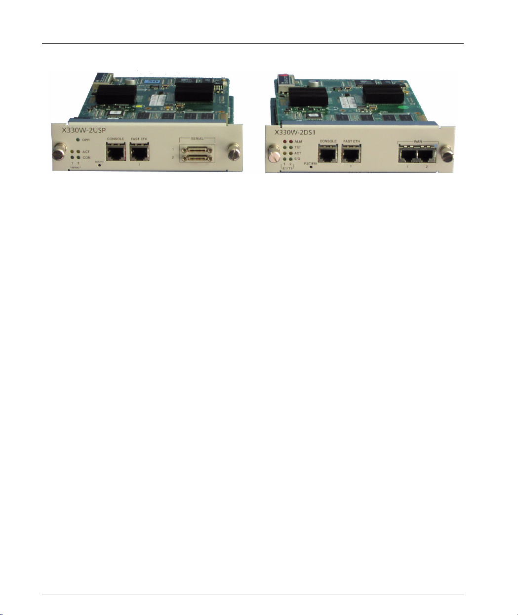
Chapter 1 Introduction
Figure 1.1 X330W-2USP and X330W-2DS1 Modules
Features
The following is a description of X330W-2DS1 and X330W-2USP features:
Layer 1 Features
X330W-2DS1
• 2 channelized/fractional E1/T1 ports, with RJ-48 connectors.
• 10/100Base-T Auto-Negotiation Fast Ethernet port.
• 100 Mbps, Full Duplex FabricFastEthernet interface, for internal connection to
the P330 switch.
• RS-232, RJ-45 port for Console and dial-in modem connection.
X330W-2USP
• 2 USP ports with standard SCSI connectors, supporting V.35, X.21, and
EIA530A protocols.
• Supports DTE serial connections up to 8 Mbps.
• 10/100Base-T Auto-Negotiation Fast Ethernet port.
• 100 Mbps, Full Duplex FabricFastEthernet interface, for internal connection to
the P330 switch.
• RS-232 RJ-45 port for Console and dial-in modem connection.
Layer 2 Features
• PPP over channeled and fractional E1/T1. X330WAN has the ability to map
several PPP sessions to a single E1/T1 interface.
• PPP over USP.
• Unframed E1 for enabling full 2.048 Mbps bandwidth usage.
2 Avaya X330WAN User’s Guide
Page 25

• Point-to-Point Frame Relay encapsulation over
• Frame Relay LMI types supported: ANSI (Annex D), ITU-T:Q-933 (Annex A0),
• Backup functionality supported between any type of Serial Layer 2 interface.
• Up to 253 VLANs on the FabricFastEthernet LAN interface. VLANs assigned on
• Auto-Negotiation - the Fast Ethernet port supports Auto-Negotiation that
Layer 3 Features
• RIP v1/v2 routing protocols.
• Single Area OSPF routing protocol - X330WAN can be configured as an OSPF
• VRRP redundancy protocol - supported only on the X330WAN’s LAN (Fast
• Equal-Cost MultiPath (ECMP) - enables load balancing by splitting traffic
• Enhanced routing configuration for efficient bandwidth usage, including RIP
Features
channelized/fractional/unframed E1/T1 ports or over a USP interface.
LMI-Rev1, and No LMI.
For more information refer to "Backup Interfaces" on page 44.
the FabricFastEthernet port enable the X330WAN to perform inter-VLAN
routing. Specific VLANs can be configured to have access to the WAN while
others can be configured to deny such access.
automatically detects and supports the duplex mode and speed of a connected
device. X330WAN can be connected to Ethernet or Fast Ethernet equipment at
full or half duplex without any further configuration.
Autonomous System Boundary Router (ASBR) by configuring route
redistribution. You can install X330WAN in the OSPF backbone area (area
0.0.0.0) or in any OSPF area that is part of a multiple areas network. X330WAN
can not be configured to be an OSPF area border router.
Ethernet and FabricFastEthernet) ports.
between several equivalent paths.
Distribution Lists. For more information, refer to "Enhanced Routing
Capabilities" on page 35.
Convergence Features
• Quality of Service (QoS) - X330WAN supports the ability to separate traffic
into 4 strict priority queues per egress serial interface. The queue assignment is
performed using Policy. For more detailed information, refer to "Frame Relay
Encapsulation" on page 46.
• Guaranteed delay for VoIP traffic - X330WAN supports VoIP Queue mode. In
this mode traffic labelled as voice traffic receives preference over all other
traffic. The X330WAN default VoIP queuing mode is optimized for the G.729
CODEC. For more detailed information, refer to "Frame Relay Encapsulation"
on page 46.
Avaya X330WAN User’s Guide 3
Page 26

Chapter 1 Introduction
• Weighted Random Early Detection (WRED) - X330WAN uses WRED on its
ingress and egress queues in order to improve the performance of the network
when overloaded. The purpose of WRED is to indicate to transmitting hosts to
reduce their transmission speed when the ingress X330WAN queues are
congested. For more detailed information, refer to "Frame Relay Encapsulation"
on page 46.
• Policy - Each Serial interface, the Fast Ethernet port, and the FabricFastEthernet
interface can have an ingress and egress active Policy list. X330WAN can
enforce QoS Policy on routed packets and change their 802.1p priority,
according to the packet characteristics.
X330WAN allows changing the DSCP value in the IP header of a packet based
on packet characteristics (DSCP coloring).
In addition, X330WAN supports Access Control policies that define which
packets should be forwarded or denied access to the network. For more detailed
information, refer to "Policy" on page 48.
• RTP Header Compression - X330WAN saves up to 60% of the bandwidth
necessary using RTP compression. It also enhances the efficiency of voice
transmission over the network by compressing the headers of Real Time
Protocol (RTP) packets, thereby minimizing the overhead and the delays
involved in RTP implementation. For more detailed information, refer to "RTP
Header Compression (cRTP)" on page 53.
Sample Applications
The primary uses of the X330WAN are:
• Branch Office connectivity to Headquarters.
• Small/Medium Business connectivity directly to an ISP (Internet Service
Provider).
For illustrations and configuration examples of common applications, refer to
Chapter 4: Operational Concepts and Configuration Examples.
Branch Office Connectivity to Headquarters
X330WAN enables connecting branch office LANs, based on the P330 switch, to a
central office to access the corporate WAN. Each branch office in this solution is
connected to the headquarters office via a leased line or Frame Relay service, and
therefore uses the Internet services supplied via the headquarters ISP. The branch
office can also connect directly to the Internet, independent of the headquarters
office.
Installing an X330WAN Access Router in an Avaya G700 Media Gateway provides
cost-effective and space-saving IP Telephony and WAN routing for SMEs
(Small/Medium Enterprises).
4 Avaya X330WAN User’s Guide
Page 27

The Avaya G700 Media Gateway and P330 switch can be stacked together to
provide a comprehensive converged data and VoIP solution.
Small/Medium Business Connectivity Directly to a Service Provider
X330WAN enables SMEs to connect their LAN directly to an ISP, using a P330
switch. This solution provides independence and flexibility to the SMEs for data
flow and other Internet services.
Functional Concepts Overview
Combining resources is an important component for success for today’s businesses.
X330WAN supplies you with combined required access functionality for branch
offices and SMEs. X330WAN includes all functions necessary for branch office and
SME connectivity.
X330WAN is designed to incorporate the following concepts:
• WAN access
•Routing
•Security
•Convergence
Functional Concepts Overview
WAN Access
WAN access enables data and VoIP transfer by providing a link for routing packets
between the WAN and Ethernet/LAN interfaces. WAN access enables connecting
branch offices to headquarters, and providing fast access to the Internet and e-mail.
VoIP services are enhanced when X330WAN is combined with the Avaya G700
Media Gateway or to the Avaya DEFINITY
®
Communications Server.
Routing
The X330WAN access router modules provide routing capabilities to a P330 switch.
X330WAN routes packets between the WAN and LAN interfaces in the access
router module. X330WAN provides support for the major routing protocols, as well
as a Layer 3/Layer 4 Policy classifier. The Policy classifier works per Layer 2
interface and per direction, controlling access and QoS (tagging and mapping to
internal queuing mechanism). X330WAN independently controls the traffic flow in
the P330 from the LAN to the WAN. For more information about these features,
refer to Chapter 4: Operational Concepts and Configuration Examples.
Avaya X330WAN User’s Guide 5
Page 28

Chapter 1 Introduction
Security
Currently security can be implemented with X330WAN by connecting the
X330WAN’s Fast Ethernet port via an external firewall to a port on the P330 switch.
The X330WAN module is connected to the Internet via its WAN ports. For more
information and a sample configuration, refer to "Configuring the X330WAN for
use with an External Firewall" on page 43.
Note: X330WAN contains the infrastructure for all security functionality planned
for future releases, such as Firewall and VPN. Licenses will be issued for the
different security options as the features become available.
Convergence
X330WAN enables a combined data and VoIP solution when used in conjunction
with a VoIP gateway, such as the Avaya S8300 Media Server. You can build your
VoIP network using several topologies, such as:
• Connecting a S8300 Media Server or G700 Media Gateway to the LAN’s
P333T/P333T-PWR/P330 stack, and inserting X330WAN in an expansion slot
of one of the above devices.
• Connecting a DEFINITY with Prowler and CLAN cards to the LAN’s
P333T/P333T-PWR/P330 stack, and inserting X330WAN in an expansion slot
of one of the above devices.
In addition, you need to connect standard IP phones to the P330 stack in either of
the above topologies, or Avaya Legacy phones directly to the G700 Media Gateway.
Using these solutions, X330WAN provides access to the corporate WAN with endto-end QoS and Policy, ensuring the flawless functioning of the IP telephony.
Avaya X330WAN Network Management
Comprehensive network management is a key component of today’s networks.
Avaya provides multiple ways of managing X330WAN to suit your needs.
Command Line Interface (CLI)
The Avaya P330 CLI enables local or remote configuration of X330WAN. X330WAN
configurations are saved in CLI format.
The X330WAN CLI is accessed via one of the following:
• Telnet to one of the IP interfaces of X330WAN.
•Use the
Console port of the P330 stack master.
6 Avaya X330WAN User’s Guide
session wan command from the Layer 2 agent of the stack, i.e. the
Page 29

• Terminal Emulation connection to the Console port on X330WAN.
• Modem connection to the Console port on X330WAN.
Avaya P330 Device Manager (Embedded Web)
The built-in Avaya P330 Device Manager (Embedded Web Manager) allows you to
manage X330WAN using a Web browser without purchasing additional software.
This application works with the Microsoft
Navigator web browsers and Sun Microsystems Java™ Plug-in.
Access the Device Manager by browsing to the Layer 2 agent (stack) IP address
using your web browser. For more information on the Embedded Web Manager,
refer to Appendix B: Embedded Web Manager.
Multiservice Network Manager (MSNM)
When you need extra control and monitoring, or wish to manage other Avaya LAN
devices and wireless equipment, the Avaya MSNM is the right tool. This suite of
management tools provides the ease-of-use and features necessary for optimal
network utilization. MSNM supports the following operating environments:
•Windows NT
• Stand-Alone mode with Windows NT/2000.
• HP OpenView for Windows NT/2000 and Solaris 8.
®
/2000 and Solaris 8.
Requirements and Specifications
®
Internet Explorer and Netscape®
Requirements and Specifications
This section provides the X330WAN environmental requirements and technical
specifications.
Environmental Specifications
X330WAN has the following environmental specifications.
Item Description
Operating Temperature -5 to 50° C (23–122°F)
Operating Humidity 5% to 95% relative humidity, non-condensing
Avaya X330WAN User’s Guide 7
Page 30

Chapter 1 Introduction
Item Description
Mechanical Shocks TR-NWT-000063 - Network Equipment Building
Power & Heat Dissipation
X330WAN has the following power and heat dissipation statistics:
• Power for the X330WAN comes from the P330. The X330WAN operational
power is approximately 45 Watts.
• Heat dissipation: the X330WAN conforms to the P330 operating temperature
range.
System, Generic Equipment Requirements,
chapters:
4.4.1 Shock Criteria
4.4.2 Vibration Criteria
5.4.1 Shock and Vibration Test Methods
8 Avaya X330WAN User’s Guide
Page 31

Chapter 2
Installation
This chapter describes the X330WAN installation procedure, and includes the
following sections:
• Installation Safety Information - Important information before connecting the
X330WAN.
• P330 Software Support for X330WAN - Describes the P330 software versions to
support the X330WAN modules.
• Installing an X330WAN Module into an Avaya P330 Switch - Describes the
procedure for installing an X330WAN module in a P330 switch.
• X330W-2DS1 Front Panel and LEDs - Describes the X330W-2DS1 front panel
and LEDs.
• X330W-2USP Front Panel and LEDs - Describes the X330W-2USP front panel
and LEDs.
• Avaya P330 LEDs - Describes the P330 LEDs that relate to the X330WAN’s
functioning.
• Connecting the X330WAN - Describes the cables used to connect each of the
X330WAN’s ports.
• Removing an X330WAN Module from an Avaya P330 Switch - Describes the
procedure for removing an X330WAN module from a P330 switch.
Installation Safety Information
Warning: Installation and removal of X330WAN must only be performed by
qualified personnel.
Caution: Hold X330WAN only by the edges to avoid damage from static electricity.
Do not touch the top or bottom of the circuit board. If possible, wear a wrist-strap
and use an anti-static bag.
Avaya X330WAN User’s Guide 9
Page 32

Chapter 2 Installation
P330 Software Support for X330WAN
X330WAN enables you to connect your Avaya P330 switch to a WAN.
X330WAN can be inserted into Avaya P330 product line switches that include an
expansion slot. These include the following Avaya P330 family switches and
required software versions:
• Avaya P333T Embedded S/W Ver. 3.12 and higher
• Avaya P334T Embedded S/W Ver. 3.12 and higher
• Avaya P332MF Embedded S/W Ver. 3.12 and higher
• Avaya P333R Embedded S/W Ver. 3.12 and higher
• Avaya P333R-LB Embedded S/W Ver. 3.12 and higher
• Avaya P333T-PWR Embedded S/W Ver. 3.12 and higher
X330WAN can only be installed in the above Avaya switches using the firmware
(embedded software) version 3.12 or higher. If you need to upgrade the software,
obtain the latest version of the software from http://www.avaya.com/support
download it according to the instructions found in the User’s Guide that
accompanies your Avaya P330 switch.
You can view the firmware version of your Avaya switch using the
show image version command.
and
Installing an X330WAN Module into an Avaya P330 Switch
Note: The X330WAN modules are not hot swappable. Removing/inserting an
X330WAN with the power on resets the enclosing P330 switch.
To install an X330WAN access router module:
1 Remove the blanking plate or other expansion module from the P330 switch
designated to house the X330WAN module.
2 Insert the X330WAN module gently into the slot, ensuring that the lower
printed circuit board (PCB) is aligned with the guide rails.
The PCB, not the metal base plate, fits into the guide rail.
3 Firmly press the X330WAN module until it is completely inserted into the P330
switch. If the module is not inserted completely, the P330 switch can not
successfully reset.
4 Gently tighten the two screws on the front panel of the X330WAN module.
Note: Do not operate the Avaya P330 switch with the expansion slot open. If there is
no expansion module in the slot, cover it with the supplied blanking plate.
10 Avaya X330WAN User’s Guide
Page 33

5 Follow the post-installation checks, as described in "Power On Self Test" on
page 11.
Power On Self Test
When you power up the Avaya P330 switch with a X330WAN module inserted,
both the P330 switch and the X330WAN perform a self test. This test takes about 40
seconds to complete, and includes:
• Checksum tests of boot and system areas of Flash memory
• System memory tests
• MAC address verification test
• System timer test
• CAM (Contents Addressable Memory) tests
• Console Port tests
• Internal packet forwarding tests
• Switch and expansion module ASIC (Application Specific Integrated Circuit)
tests
• Switch and expansion module ASIC memory tests
• Expansion module interface tests
• Expansion module packet forwarding tests
After you insert an X330WAN access router module into a powered P330 switch,
causing a reset, or after a power cycle of the host P330 switch, the X330W-2DS1
startup sequence is as follows:
1 Initially all LEDs light for 15 seconds and then switch off.
2 The ALM LEDs light for 15 seconds and then switch off.
3 The TST LEDs lights for 15 seconds and then switch off.
4 At this point, the ALM LED lights again if there is no line signal detected on the
E1/T1 ports. If a signal is detected on the line, the SIG LEDs light and the ALM
LEDs switch off.
The X330W-2USP startup sequence is as follows:
1 All LEDs light for 15 seconds, then switch off.
2 All LEDs remain off for 15 seconds.
3 The OPR LED lights and remains on.
Installing an X330WAN Module into an Avaya P330 Switch
Note: LED Number 51 on the Avaya P330 switch should be ON during the self-test
procedure.
The X330WAN module must be inserted completely for the P330 switch to
successfully reset.
Avaya X330WAN User’s Guide 11
Page 34

Chapter 2 Installation
X330W-2DS1 Front Panel and LEDs
The front panel of the X330W-2DS1 has two columns of four LEDs each, one for
each Serial (WAN) port in the access router module. There is also a Fast Ethernet
port, and a Console port for directly connecting a terminal. Between the LEDs and
the Console port there is a RST/FIV button for manually resetting the module.
Figure 2.1 X330W-2DS1 Front Panel
Table 2.1 describes the LEDs on the front panel of the X330W-2DS1.
Table 2.1 X330W-2DS1 LED Descriptions
LED Name Color Description LED Status
ALM Red Alarm
ON - Module is initializing, or
when an alarm state exists on an
interface.
OFF - Initialization successful,
module software functioning
properly, no alarm conditions on
an interface.
ON - Port is being initialized or
TST Green Test
ACT Yellow Active
SIG Green Signal
12 Avaya X330WAN User’s Guide
loopback is active.
OFF - Port initialization completed
and loopback is not active.
ON - At least one PPP/Frame
Relay session is active.
OFF - No active PPP/Frame Relay
session.
ON - A signal is detected on the
port.
OFF - No signal is detected on the
port.
Page 35

X330W-2USP Front Panel and LEDs
The front panel of the X330W-2USP has a column of two LEDs for each Serial port in
the access router module, and an Operational LED displaying module status. There
is also a Fast Ethernet port, and a Console port for directly connecting a terminal.
Between the LEDs and the Console port there is a RST/FIV button for manually
resetting the module.
Figure 2.2 X330W-2USP Front Panel
Table 2.1 describes the LEDs on the front panel of the X330W-2USP.
Table 2.2 X330W-2USP LED Descriptions
LED Name Color Description LED Status
X330W-2USP Front Panel and LEDs
ON - The module is operational.
OPR Green Operational
ACT Yellow Active
CON Green Connected
Avaya X330WAN User’s Guide 13
OFF - The module initialization has
failed.
ON - At least one PPP/Frame
Relay session is active.
OFF - No PPP or Frame Relay
sessions are active.
ON - DCD, DSR, and CTS are
active.
OFF - A line is inactive or an
interface is down.
Page 36

Chapter 2 Installation
Avaya P330 LEDs
Figure 2.3 shows an Avaya P330 Switch front panel and a detailed view of the LEDs
used when an X330WAN is installed.
Figure 2.3 Avaya P330 Front Panel LED Indicators
Note: All LEDs light while the P330 switch resets.
The P330 switch front panel LEDs consist of Port LEDs and Function LEDs, as
shown in Figure 2.3. The Function LEDs display the selected function for the ports
indicated by the Port LEDs. The function is selected by pressing the Left/Right
switch until the desired function LED is illuminated. Pressing the same switch again
moves to the next function.
When the X330WAN module is installed in a P330 switch, Port LED number 51
displays the status of the X330WAN Fast Ethernet port according to the selected
function. Port LED number 51 is off when Fast Ethernet port is administratively
disabled.
For a description of the other LEDs on the front panel of the Avaya P330 switch,
refer to the User’s Guide that accompanies your switch.
14 Avaya X330WAN User’s Guide
Page 37

Connecting the X330WAN
This section describes the cables used to connect the X330WAN.
Connecting the E1/T1 WAN Ports
Use an RJ-48C cable, minimum 26 gauge, to connect the E1/T1 WAN ports on the
X330WAN to the network wall jack.
Connecting the USP Ports
X330W-2USP supports several interface types for the Serial ports. The X330W-2USP
automatically detects the cable type used and determines the Serial protocol
needed. You can order the following types of 3 meter length adaptor cables for the
different interfaces.
• V.35 interface - SCSI-M34 DTE cable
• X.21 interface - SCSI-DB-15 DTE cable
• EIA530A interface - SCSI-DB-25 DTE cable
Note: The X330W-2USP module is a DTE, therefore the cables associated with this
module have male connectors on both ends. If a cable with a female connector on
one end is used (a DCE cable), the X330W-2USP CLI alerts you that the wrong cable
is connected.
Connecting the X330WAN
For pinouts of the above cables, refer to Appendix A: Interface Specifications.
Connecting the Fast Ethernet (10/100Base-T) Port
Connect a UTP Category 5 cable with an RJ-45 connector to the 10/100Base-T port.
The maximum UTP cable length connected to the 10/100Base-T port is 100m
(328 ft.).
You can obtain appropriate cables from your local supplier.
Connecting the Console Port
The port on the front panel labelled “Console” is for connecting a terminal or a
modem, and has an RJ-45 connector. Connect the X330WAN module to a terminal
using the supplied console cable and the RJ-45 to DB-9 adaptor. To connect a
modem, use the supplied cable and an RJ-45 to DB-25 adaptor.
For pinouts of the Console cables, refer to Appendix A: Interface Specifications.
Avaya X330WAN User’s Guide 15
Page 38

Chapter 2 Installation
Note: The cable and two adaptors can be found in the Avaya P330 accessory set, and
are clearly marked.
Removing an X330WAN Module from an Avaya P330 Switch
To remove an X330WAN module from a P330 switch:
1 Loosen the screws on the front panel of the X330WAN module that secure the
module to the P330 switch.
2 Grasp the two screw knobs and pull gently but firmly towards yourself.
The X330WAN module slides out of the slot.
3 Insert another expansion module or the blanking plate into the switch.
16 Avaya X330WAN User’s Guide
Page 39

Chapter 3
Initial Configuration
This chapter describes the initial configuration of the X330WAN, and includes the
following sections:
• Configuring the X330WAN - Describes how to configure an X330WAN Fast
Ethernet, FabricFast Ethernet, E1/T1, USP, or Loopback interface, and which
commands to use to display and save your configuration.
• X330WAN Default Settings - Lists the default settings of the X330WAN.
Configuring the X330WAN
X330WAN can be configured using the Command Line Interface (CLI) utility, the
built-in Avaya P330 Device Manager (Embedded Web), or Avaya MultiService
Network Manager (MSNM
For instructions on using the CLI, refer to Chapter 6: X330WAN CLI Commands. For
instructions on using the Device Manager or Avaya MultiService Network
Manager
Manager User’s Guide on the Documentation and Utilities CD.
The CLI is command-line driven and does not have any menus. To activate a
configuration option, type the desired command at the prompt and press Enter.
This section describes how to do the following using the CLI:
• Establish a console and modem connection.
• Configure an X330WAN Loopback, Fast Ethernet, FabricFast Ethernet, E1/T1,
• Check and save your configuration.
• Establish a Telnet session.
™, refer to the Avaya MultiService Network Manager or P330 Device
and USP interface.
™).
Establishing a Console Connection
Perform the following steps to connect a terminal to the Console port of the
X330WAN module for configuration of WAN parameters using the CLI:
1 Use the supplied cable to attach the RJ-45 console connector to the Console port
on the X330WAN module. Connect the DB-9 connector to the serial (COM) port
on your PC/terminal.
2 Use the following port settings on the terminal:
— Baud Rate - 9600 bps
— Character Size - 8
Avaya X330WAN User’s Guide 17
Page 40

Chapter 3 Initial Configuration
—Parity - None
— Stop Bit - 1
— Flow Control - None
— Terminal Emulation - VT-100
Note: The terminal connected to the Console port must be configured with these
settings.
3 Press Enter.
4 When prompted for a Login Name, enter the default name
5 When promoted for a password, enter the password
Establishing a Modem Connection
A PPP connection with a modem can be established only after the X330WAN is
configured with an IP address and net-mask. Also, the parameters used in the
X330WAN must be compatible with the modem’s parameters.
All CLI commands mentioned in this section are described in Chapter 6: X330WAN
CLI Commands.
To configure a modem interface:
1 Connect a terminal to the console port of the X330WAN, as described in
"Establishing a Console Connection" on page 17.
2 At the prompt, type:
3 Enter an IP address and subnet mask for the X330WAN to connect via its PPP
interface using the
root.
root.
interface Console and press Enter.
ip address <ip address> <mask> command.
Note: The PPP interface, configured within the interface console context, must
be on a different subnet from the router interfaces.
4 Set the baud rate, PPP authentication, and PPP timeout required to match your
modem using the following commands:
speed <9600|19200|38400>
ppp authentication <chap|none|pap>
timeout absolute <time>
5Type:
async mode interactive
. The time entered is in minutes.
The CLI responds with the following:
Entering the Modem mode would occur automatically upon proprietary
modem-cable plug-in into the console port. The terminal mode would
be restored automatically upon insertion of proprietary terminal-
cable
.
18 Avaya X330WAN User’s Guide
Page 41

6 Connect the Console port to the modem’s DB-25 port using the DB-25 to RJ-45
connector. The X330WAN enters Modem mode.
7 Dial into the module from a remote station, and open a Telnet session to the PPP
interface IP address configured in step 3.
Checking the Modem Configuration
After establishing a modem connection, use the
command to display information regarding your modem interface. Verify that the
output information is correct.
Establishing a Telnet Connection
Perform the following steps to establish a Telnet connection to the X330WAN for
configuration of WAN parameters. Telnet directly to one of the IP interfaces of the
X330WAN:
1 Connect your station to the network.
2 Verify that you can communicate with the X330WAN using the
ping <host> [<interval> [<size>]] command to the IP of the X330WAN. If
there is no response, check the IP address and default gateway of both the
X330WAN and the station using the
3 From the Microsoft Windows taskbar of your PC, click Start and then Run (or
from the DOS prompt of your PC), then start the Telnet session by typing:
telnet <IP address of X330WAN>
For example:
telnet 149.49.32.134
Configuring the X330WAN
show interface console
show ip route command.
Note: You can also Telnet the IP address of the P330 stack. If you Telnet the IP
address of the stack, a connection is established with the Switch CLI entity of the
Master module of the stack.
If you want to connect to the X330WAN CLI entity, use the
number in stack> command.
4 When prompted for a Login Name, enter the default name
5 When prompted for a password, enter
root. You can now configure the
session wan <module
root.
X330WAN.
Avaya X330WAN User’s Guide 19
Page 42

Chapter 3 Initial Configuration
Configuring Loopback Interfaces
All CLI commands mentioned in this section are described in Chapter 6: X330WAN
CLI Commands.
To configure Loopback interfaces:
1 Enter the Interface Loopback mode using the
interface Loopback [<interface number>[.ip-interface]] command.
For example: typing
the Loopback1 interface parameters.
The prompt changes to
where N is the switch number and n is the Loopback interface number.
2Use the
and subnet mask to the interface.
3Type
The prompt returns to
Note: The first IP interface created in the X330WAN automatically becomes the PMI
(Primary Management Interface), described in detail on page 34. It is recommended
to configure the Loopback interface as the first Layer 2 interface and to configure an
IP interface on it. After the PMI is configured, the following message appears:
The primary management interface has changed.
For this change to take effect, you need to copy running-config
startup-config and then reset the device.
Enter the copy running-config startup-config and reset commands at this
stage.
ip address <ip address> <mask> command to assign an IP address
exit to return to Supervisor mode.
interface loopback 1 enters a context for configuring
X330WAN-2DS1-N(super-if:Loopbackn)#
X330WAN-2DS1-N(super)#
Configuring Fast Ethernet Interfaces
All CLI commands mentioned in this section are described in Chapter 6: X330WAN
CLI Commands.
To configure Fast Ethernet interfaces:
1Type
2Use the ip address <ip address> <mask> command to assign an IP address
3Type
Note: The first IP interface created in the X330WAN automatically becomes the
PMI, described in detail on page 34. It is recommended to configure the Loopback
interface as the first Layer 2 interface and to configure an IP interface on it. After the
20 Avaya X330WAN User’s Guide
interface FastEthernet 1 to enter the Interface Configuration mode.
The prompt changes to
X330WAN-2DS1-N(super-if:FastEthernet1)#
and subnet mask to the interface.
exit to return to Supervisor mode.
The prompt returns to
X330WAN-2DS1-N(super)#
Page 43

PMI is configured, the following message appears:
The primary management interface has changed.
For this change to take effect, you need to copy running-config
startup-config and then reset the device.
Enter the copy running-config startup-config and reset commands at this
stage.
Configuring the FabricFast Ethernet Interface
All CLI commands mentioned in this section are described in Chapter 6: X330WAN
CLI Commands.
To configure a FabricFast Ethernet interface:
1Use the
FabricFast Ethernet interface context, where the if-number format is
port[:vlan[.ip-interface index]].
Note: You do not need to include the ip-interface index if you configure only one IP
interface.
interface FabricFastEthernet <if-number> command to enter the
Configuring the X330WAN
2Use the
ip address command to assign an IP address to the interface.
For example: To configure the IP addresses 10.10.10.1 on VLAN 2 and 20.20.20.1
and 30.30.30.1 on VLAN 3 perform the following:
X330WAN-2USP-1(super)# interface FabricFastEthernet 1:2
X330WAN-2USP-1(super-if:FabricFastEthernet1:2)# ip address
10.10.10.1 24
X330WAN-2USP-1(super-if:FabricFastEthernet1:2)# exit
X330WAN-2USP-1(super)# interface FabricFastEthernet 1:3.1
X330WAN-2USP-1(super-subif:FabricFastEthernet1:3.1)# ip address
20.20.20.1 24
X330WAN-2USP-1(super-subif:FabricFastEthernet1:3.1)# exit
X330WAN-2USP-1(super)# interface FabricFastEthernet 1:3.2
X330WAN-2USP-1(super-subif:FabricFastEthernet1:3.2)# ip address
30.30.30.1 24
X330WAN-2USP-1(super-subif:FabricFastEthernet1:3.2)# exit
Note: The first IP interface created in the X330WAN automatically becomes the
PMI, described in detail on page 34. It is recommended to configure the Loopback
interface as the first Layer 2 interface and to configure an IP interface on it. After the
PMI is configured, the following message appears:
Avaya X330WAN User’s Guide 21
Page 44

Chapter 3 Initial Configuration
The primary management interface has changed.
For this change to take effect, you need to copy running-config
startup-config and then reset the device.
Enter the copy running-config startup-config and reset commands at this
stage.
Configuring E1/T1 Interfaces
All CLI commands mentioned in this section are described in Chapter 6: X330WAN
CLI Commands.
For a list of X330WAN default settings, see "X330WAN Default Settings" on page 28,
or use the
current settings.
To configure E1 or T1 interfaces:
1Use the
2Use the
3 Use the following commands if you want to change the clock source, frame type
4Use the
5Use the
show controllers <port number> command to display all of the
show controllers <port number> command to check if your
controller’s mode is configured as E1 or T1.
Use the
ds-mode [e1|t1] command to set the controller’s mode to E1 or T1.
Changing the line type requires resetting the module.
controller [e1|t1] <port number> command to enter the context of
the port to be configured.
The prompt changes to
where N is the switch number and n is the port number.
and linecode parameters from their default settings:
clock source [line|internal]
framing
[sf|esf] for T1 lines or framing [crc4|no-crc4|unframed] for E1
lines.
linecode [ami|b8zs] for T1 lines or linecode [ami|hdb3] for E1 lines.
cablelength [long|short] for T1 lines.
For T1 mode proceed to step 5.
channel-group <channel-number> timeslots <timeslot-list>
command to specify the channel group and time slots to be mapped. For
example, typing
channel group 1 timeslots 1,3-5,7 configures time slots numbered 1, 3-5
and 7 to be mapped in channel-group number 1.
Proceed to step 6.
channel-group <channel number> timeslots <timeslot list>
speed [56|64]
mapped and DS0 speed in kbps. For example, typing
channel group 1 timeslots 1,3-5,7 speed 64 configures time slots
numbered 1, 3-5, and 7 to be mapped in channel-group number 1 and the DS0
speed to 64 kbps.
X330WAN-2DS1-N(super-controller:n)#
command to specify the channel group, time slots to be
22 Avaya X330WAN User’s Guide
Page 45

Configuring the X330WAN
The default DS0 speed is 56 kbps
6Type
exit to return to Supervisor mode.
The prompt returns to
X330WAN-2DS1-N(super)#
7Use the interface Serial <port:channel-group<.ip-interface>>
command to configure each channel group as a virtual Serial interface. Specify
the port number and channel group number to modify.
For example: typing
interface Serial 1:1 configures a Serial interface on
port number 1 with a channel group number 1.
8 Change the encapsulation to Frame Relay if required, using the
frame-relay
command.
encapsulation
If Frame Relay encapsulation was selected, continue with step 13.
Note: After the Serial interface is created, its default encapsulation is PPP.
9Use the
ip address <ip address> <mask> command to assign an IP address
and subnet mask to the interface.
10 Type
exit to return to Supervisor mode.
The prompt returns to
X330WAN-2DS1-N(super)#
This completes the procedure for PPP encapsulation.
11 Repeat step 4 through step 10 if you want to configure another serial interface
on the same E1/T1 port.
12 Repeat step 2 through step 10 if you want to configure another E1 or T1
interface.
13 Use the
frame-relay lmi commands to change the Local Management
Interface (LMI) parameters from their default values if required, or use the
frame-relay traffic-shaping command to activate Traffic Shaping on the
Frame Relay interface. For more information on Traffic Shaping, refer to "Traffic
Shaping and Marking" on page 47.
14 Type
15 Use the
exit to return to Supervisor mode.
interface serial <if-number>[<if-link-type>] command to
enter the Frame Relay Sub-interface context. (For example, typing
serial 2:3.1 point-to-point
creates a Point-to-Point type Sub-interface 1
interface
on port 2, channel-group 3.)
Note: Currently only Point-to-Point Sub-interface types are supported.
16 Configure a Data Link Connection Identifier (DCLI) for the Sub-interface using
the
frame-relay interface-dlci <DLCI number> command.
17 If required, configure a Priority DLCI Group using the
priority-dlci-group <DLCI1>[<DLCI2>[<DLCI3>[<DLCI4>]]]
Avaya X330WAN User’s Guide 23
frame-relay
command.
Page 46

Chapter 3 Initial Configuration
For more information, refer to "Priority DLCI" on page 46.
18 Configure an IP address for the Sub-interface using the
address> <mask> [<admin state>]
19 Type
exit to return to Supervisor mode.
20 Repeat step 3 through step 6 to configure additional Frame Relay Sub-interfaces
on the same Frame Relay interface.
Note: If the Unframed framing option was selected in step 3 for an E1 port, a
Channel Group is automatically created comprising the entire E1 bandwidth. This
Channel Group has the number ‘0’, and for all the subsequent configuration for this
interface use the context interface serial n:0 where ‘n’ is the port number.
Note: The first IP interface created in the X330WAN automatically becomes the
PMI, described in detail on page 34. It is recommended to configure the Loopback
interface as the first Layer 2 interface and to configure an IP interface on it. After the
PMI is configured, the following message appears:
The primary management interface has changed.
For this change to take effect, you need to copy running-config
startup-config and then reset the device.
Enter the copy running-config startup-config and reset commands at this
stage.
ip address <ip
command.
Table 3.1 provides the different configuration contexts for the X330W-2DS1 CLI.
This table uses the following legend:
• x = physical port number
• y = channel group
• z = sub frame relay interface index
• w = IP interface index
•v = VLAN number
Table 3.1 X330W-2DS1 CLI Interface Contexts
CLI Interface Context PPP Frame Relay
Controller
Serial
Sub Frame Relay N/A
24 Avaya X330WAN User’s Guide
controller e1 (t1) x
interface serial x:y interface serial x:y
controller e1 (t1) x
interface serial x:y.z
point-to-point
Page 47

Table 3.1 X330W-2DS1 CLI Interface Contexts (Continued)
CLI Interface Context PPP Frame Relay
Configuring the X330WAN
IP
FastEthernet
FabricFastEthernet
interface serial x:y.w interface serial x:y.z.w
interface fastethernet 1.w interface fastethernet 1.w
interface fabricfastethernet
1:v.w
Configuring USP Interfaces
All CLI commands mentioned in this section are described in Chapter 6: X330WAN
CLI Commands.
For a list of X330WAN default settings, see "X330WAN Default Settings" on page 28,
or use the
of the current settings.
To configure USP interfaces:
1Use the
2 Use the following commands if you want to change the idle characters,
Note: The transmitter-delay command is used usually when the DCE equipment
that is connected directly to the X330W-2USP, or the router on the WAN have a
receive buffer not large enough to hold the traffic sent by the X330W-2USP. In this
case, configure
order to preserve the high performance that you had when
was configured to 0 on the X330W-2USP.
show interfaces [<type>] [<identifier>] command to display all
interface serial <if-number> command to enter the context of the
port you want to configure.
transmitter delay, encoding type, and bandwidth parameters from their default
settings:
idle characters <flags|marks>
transmitter-delay <number>
interface fabricfastethernet
1:v.w
transmitter-delay on the DCE equipment or the remote router in
transmitter-delay
nrzi-encoding
bandwidth <kilobits size>
3 If required, change the interface encapsulation to Frame Relay using the
encapsulation frame-relay command. If you selected Frame Relay
encapsulation, continue with step 7.
4Use the
ip address <ip address> <mask> command to assign an IP address
and a Subnet mask to the interface.
5Type
Avaya X330WAN User’s Guide 25
exit to return to Supervisor mode.
Page 48

Chapter 3 Initial Configuration
Note: If you need to define more than one IP address on the interface, enter a new
interface serial n.m context, where n is the port number and m is the additional
IP interface. (For example: typing interface serial 1.1 enables you to configure an IP
interface on interface Serial 1, in addition to the IP interface created in step 4.)
6 Repeat step 1 through step 5 to configure the second USP interface if needed.
7Use the
frame-relay lmi commands to change the Local Management
Interface (LMI) parameters from their default values if required, or use the
frame-relay traffic-shaping command to activate Traffic Shaping on the
Frame Relay interface. For more information on Traffic Shaping, refer to "Traffic
Shaping and Marking" on page 47.
8Type
9Use the
exit to return to Supervisor mode.
interface serial <if-number>[<if-link-type>] command to
enter the Frame Relay Sub-interface context. (For example, typing
serial 2.1 point-to-point
port 2.)
Note: Currently only Point-to-Point Sub-interface types are supported.
interface
creates a Point-to-Point type Sub-interface 1 on
10 Configure a Data Link Connection Identifier (DLCI) for the Sub-interface using
the
frame-relay interface-dlci <DLCI number> command.
11 If required, configure a Priority DLCI Group using the
priority-dlci-group <DLCI1>[<DLCI2>[<DLCI3>[<DLCI4>]]]
frame-relay
command.
For more information, refer to "Priority DLCI" on page 46.
12 Configure an IP address for the Sub-interface using the
address> <mask> [<admin state>]
13 Type
exit to return to Supervisor mode.
command.
ip address <ip
14 Repeat step 9 through step 12 to configure additional Frame Relay
Sub-interfaces on the same Frame Relay interface.
Table 3.1 provides the different configuration contexts for the X330W-2USP CLI.
This table uses the following legend:
• x = physical port number
• y = channel group
• z = sub frame relay interface index
• w = IP interface index
26 Avaya X330WAN User’s Guide
Page 49

•v = VLAN number
Table 3.2 X330W-2USP CLI Interface Contexts
CLI Interface Context PPP Frame Relay
Configuring the X330WAN
Serial
Sub Frame Relay N/A
IP
FastEthernet
FabricFastEthernet
interface serial x interface serial x
interface serial x.z point-topoint
interface serial x.w interface serial x.z.w
interface fastethernet 1.w interface fastethernet 1.w
interface fabricfastethernet
1:v.w
interface fabricfastethernet
1:v.w
Checking the Loopback, Fast Ethernet, E1/T1/USP, IP Interface Configuration
After configuring the new interface, you can perform the following tests to verify
that the new interface is operating correctly.
• For the X330-2DS1, use the
status of the controller for E1/T1 interfaces.
•Use the
show interfaces <type> <identifier> command to display
information on all interfaces: Fast Ethernet, FabricFast Ethernet, Serial, Console,
and Loopback. Verify that the output information is correct.
•Use the
show frame-relay pvc [<interface-name>|<dlci number>]
command to display the Frame Relay interface configuration.
•Use the
show ip interface [<interface-name>|
<IP interface>|<ip-address>] command to display IP interface
configured Serial and Ethernet ports.
•Use the
show running-config command to display the configuration running
on the switch.
•Use the
show startup-config command to display the configuration loaded
at startup.
•Use the
ping <host> [<interval> [<size>]] command to send ICMP echo
request packets to another node on the network. Each node is periodically
pinged and checked if an answer was received. This checks host reachability
and network connectivity.
show controllers <port> command to display the
Avaya X330WAN User’s Guide 27
Page 50

Chapter 3 Initial Configuration
Saving Your Configuration
To save your configuration, type copy running-config startup-config. This
copies your X330WAN configuration from the current VRAM Running
Configuration to the Startup Configuration NVRAM.
Note: Unsaved configurations are lost after each reset or after a power failure.
X330WAN Default Settings
The default settings for the X330WAN and its ports are determined by its firmware.
These default settings are subject to change. Newer versions of the software for the
X330WAN can be downloaded from the Avaya Network Software Download Web
site at http://www.avaya.com/support
Table 3.3 provides the X330W-2DS1 default settings.
Table 3.3 X330W-2DS1 Default Settings
Function Default Setting
.
Port Speed (Fast Ethernet) 100 Mbps
Port Duplex (Fast Ethernet) Full Duplex
Auto-Negotiation (Fast Ethernet) Enabled
WAN mode (WAN) T1
Framing (WAN) SF for T1, CRC4 for E1
Linecode (WAN) AMI for T1, HDB3 for E1
Clock Source (WAN) line
Cable Length (for T1) long, gain26, 0db
Speed (for T1) 56
SNMP Community public
Avaya X330WAN CLI Entry Login Login name:
28 Avaya X330WAN User’s Guide
root, Password: root
Page 51

Table 3.4 provides the X330W-2USP default settings.
Table 3.4 X330W-2USP Default Settings
Function Default Setting
Port Speed (Fast Ethernet) 100 Mbps
Port Duplex (Fast Ethernet) Full Duplex
Auto-Negotiation (Fast Ethernet) Enabled
Encoding NRZ
Bandwidth 2048Kbps
Line-Up Indicator Signal DCD
SNMP Community public
X330WAN Default Settings
Avaya X330WAN CLI Entry Login Login name:
root, Password: root
Avaya X330WAN User’s Guide 29
Page 52

Chapter 3 Initial Configuration
30 Avaya X330WAN User’s Guide
Page 53

Chapter 4
Operational Concepts and Configuration Examples
This chapter provides information about the X330WAN functional concepts, as well
as sample configurations illustrating the implementation of these concepts. This
chapter contains the following sections:
• Detailed Interface Concepts - Describes the X330WAN physical and virtual
interfaces, and their uses.
• Enhanced Routing Capabilities - Provides information about Static Route
Configuration, Export Default Metric, OSPF Dynamic Cost Support, RIP
Distribution Access Lists, and Fragmentation and Reassembly.
This section contains a sample configuration illustrating the implementation of
these concepts.
• Backup Interfaces - Provides a description of backup interfaces, and describes
how to implement them on X330WAN.
• Frame Relay Encapsulation - Provides information about the X330WAN’s QoS
implementation for PPP encapsulation and Frame Relay encapsulation.
• Policy - Provides information about controlling network access to the
X330WAN.
• RTP Header Compression (cRTP) - Describes the X330WAN’s implementation
of cRTP.
• QoS and VoIP Treatment - Describes how X330WAN uses Quality of Service,
and handles VoIP traffic.
• VoIP Implementation with a G700 Media Gateway and an S8300 Media
Server - Provides a sample configuration illustrating the implementation of the
above concepts.
• VoIP Implementation with DEFINITY (CLAN and Prowler) - Provides a
sample configuration illustrating the above concepts with DEFINITY.
Detailed Interface Concepts
X330WAN includes physical, Layer 2 virtual, and Layer 3 routing interfaces.
Physical Interfaces
The following are the X330WAN physical interfaces:
• WAN Interfaces – 2 ports, configurable for E1 or T1, or 2 USP ports.
Avaya X330WAN User’s Guide 31
Page 54

Chapter 4 Operational Concepts and Configuration Examples
• LAN Interface – Fast Ethernet interface.
This interface is an autosensing 10/100Mbps Fast Ethernet port. It can be used
to connect to a LAN, to an external firewall/VPN, or to a DMZ.
• P330 Switching Fabric – FabricFastEthernet interface.
This is an internal 100Mbps connection to the P330 switching fabric. It supports
VLANs, and is compatible with the P330.
When connecting the X330WAN in Access-Router Only mode (e.g., no external
VPN or firewall), this interface is used to connect to the hosting P330 switch. If
an external firewall/VPN is connected to the Fast Ethernet port, it is important
to disable this interface to prevent a direct flow of packets from the WAN to the
LAN.
• Console Interface – Used to connect a terminal for local management, or a
modem for remote management.
Layer 2 Virtual Interfaces
The following are the X330WAN Layer 2 virtual interfaces:
• Loopback – A virtual Layer 2 interface over which Loopback IP addresses are
configured. The Loopback interface represents the router by an IP address that
is always available, a feature necessary mainly for network troubleshooting.
The Loopback interface also provides a ‘Router ID’ in the OSPF routing
protocol.
Since the Loopback interface is not connected to any physical interface, an entry
in the routing table can not have the Loopback interface’s subnet as its next hop.
• VLAN (on the FabricFastEthernet Interface) – The P330 switch can have
multiple VLANs defined within its switching fabric. X330WAN supports up to
253 VLANs that can be configured over its internal FabricFastEthernet
connection.
• Serial Interface – This is a virtual interface that is created over a portion of an
E1/ T1, or USP port.
The Serial interfaces support PPP and Frame Relay encapsulation protocols.
Note: One or more IP interfaces can be defined over each Serial, Fast Ethernet, or
FabricFastEthernet interfaces.
Figure 4.1 through Figure 4.4 provide graphic representations of the X330WAN
serial interfaces.
Figure 4.1 illustrates a Layer 1 T1 port with two Channel Groups defined. All data
from each Channel Group is encapsulated using PPP protocol, and is distributed
over the multiple IP interfaces defined for each Channel Group.
32 Avaya X330WAN User’s Guide
Page 55

Detailed Interface Concepts
Figure 4.1 T1 Port with PPP Encapsulation
Figure 4.2 illustrates an E1/T1 port Channel Group. All data from the Channel
Group is encapsulated using Frame Relay protocol, and is sent via a Frame Relay
Serial interface and Sub-interfaces over the multiple IP interfaces defined using
DLCI (Data Link Connection Identifier).
Figure 4.2 E1/T1 Port with Frame Relay Encapsulation
Figure 4.3 illustrates a USP port. All data from the USP port is encapsulated using
Frame Relay protocol, and is sent via a Frame Relay Serial interface and
Sub-interfaces over the single IP interfaces defined using DLCI.
Figure 4.3 USP Port with Frame Relay Encapsulation
Figure 4.4 illustrates a USP port. All data from the USP port is encapsulated using
PPP protocol, and is sent via a Serial interface over the multiple IP interfaces
defined.
Avaya X330WAN User’s Guide 33
Page 56

Chapter 4 Operational Concepts and Configuration Examples
Figure 4.4 USP Port with PPP Encapsulation
• PMI (Primary Management Interface) - This is a unique Layer 3 interface that
can be configured over any Layer 2 interface.
The PMI is the X330WAN management interface, through which the
X330WAN’s management applications access the device. The PMI is used when
downloading software or opening an Embedded Web session to X330WAN. In
both cases, a route should exist between the TFTP server or the management
station and the PMI IP address.
Note: The first IP interface created in X330WAN automatically becomes the PMI. It
is recommended to configure the Loopback interface as the first Layer 2 interface
and to configure an IP interface on it. After the PMI is configured, the following
message appears:
The primary management interface has changed.
For this change to take effect, you need to copy running-config
startup-config and then reset the device.
Enter the copy running-config startup-config and reset commands at this
stage.
You can not delete a PMI Layer 3 interface unless it is the last interface configured,
or unless the PMI function is first assigned to another IP interface.
• Supporting an End point in Frame Relay Point to Multi-point Topology -
X330WAN supports Point-to-Point Frame Relay connections. To enable you to
use X330WAN as an end-point in a Point to Multi-Point (PTMP) topology, it
supports Inverse ARP replies, and responds to Inverse ARP queries received on
the Frame Relay Sub-interfaces with proper Inverse ARP replies.
When you connect X330WAN as an end-point in a Point to Multi-Point (PTMP)
configuration, manually increase the OSPF timers to suit this topology using the
ip ospf network point-to-multipoint command from the Interface Serial
context. This command increases the OSPF Hello and Dead Intervals to 30 and
120 seconds respectively.
34 Avaya X330WAN User’s Guide
Page 57

Enhanced Routing Capabilities
This section describes the following X330WAN routing features:
• Static Route Configuration
• Export Default Metric
• OSPF Dynamic Cost Support
• RIP Distribution Access Lists
• Fragmentation and Reassembly
The following configuration examples integrating the above concepts are provided:
• Configuring X330WAN to Connect Branch Offices to Headquarters
• Configuring the X330WAN for use with an External Firewall
Static Route Configuration
Static routes can be configured to the X330WAN. They are never timed-out, and can
only be removed by manual configuration. Deletion (by configuration) of the IP
interface deletes the static routes using this interface as well.
A static route becomes inactive whenever the underlying Layer 2 interface is down,
except for Permanent Static Routes, described on page 36. When the underlying
Layer 2 interface becomes active, the static route re-enters the routing table again.
Static routes can be configured as next using the following:
• “via interface” route - via local serial interface, as described on page 36.
• Next-hop IP address - Destinations that are reachable via another router as a
next hop. The next hop router must belong to one of the directly attached
networks for which X330WAN has an IP interface.
Two kinds of static routes can be configured, High Preference static routes which are
preferred to routes learned from any routing protocol and Low Preference static
routes which are used temporarily until the route is learned from a routing protocol.
By default, a static route has Low Preference.
Static routes can be advertised by routing protocols (i.e. RIP, OSPF) as described
under Route redistribution.
Static routes also support load-balancing similar to OSPF. You can configure up to
three next-hops for each static route in one of the following manners:
• Enter all of the next-hops using a single
next-hop to an existing static route, enter the new next-hop individually, as in
the following option.
• Enter each next-hop individually with it’s own
Enhanced Routing Capabilities
ip route command. To add a new
ip route command.
Note: Using the no ip route command deletes the route including all of its
next-hops, whether entered individually or with a single command.
Avaya X330WAN User’s Guide 35
Page 58

Chapter 4 Operational Concepts and Configuration Examples
For example: To specify next-hops 149.49.54.1 and 149.49.75.1 as a static route to the
network 10.1.1.0, perform one of the following:
•Use the single
ip route 10.1.1.0 24 149.49.54.1 149.49.75.1 command
specifying all next-hops together.
• Use the individual
10.1.1.0 24 149.49.75.1
ip route 10.1.1.0 24 149.49.54.1 and ip route
commands.
Note: Next-hops can only be added to an existing static route if they have the same
preference and metric as the currently defined next-hops.
X330WAN supports the following Static Route configurations:
• “via interface” Static Route
• Permanent Static Route
•Discard Route
These configurations are described below.
“via interface” Static Route
PPP and Frame Relay allow for a Layer 3 interface to be established without
knowing in advance what the next-hop on the other side of a Serial link is. In this
case you can specify a Serial Layer 2 interface as a next-hop instead of providing a
specific next-hop IP address. This is equivalent to specifying the node on the other
side of the Serial link as the next-hop when its IP address is unknown. The “via
interface” option is configured by specifying the type and the number of the Serial
interface using the
For example: The command
ip route command.
ip route 193.168.10.0 24 serial 1:1 creates a
static route to the network 193.168.10.0 24 via the Serial 1:1 interface.
A static route can have both “via interface” and IP addressed next-hops, with a
maximum of three next-hops. If such a combination is required, separate
commands should be used for the “via interface” static route and the IP addressed
next-hop routes. Also, if more than one “via interface” next-hops are required, each
must be configured by separate
ip route commands.
ip route
Permanent Static Route
X330WAN enables you to configure a static route as a permanent route.
Configuring this option prevents the static route from becoming inactive whenever
the underlying Layer 2 interface is down. This prevents routing table updates from
being sent each time an interface goes up or down when there is a fluctuating Layer
2 interface on the static route.
Configure the ‘permanent’ option using the
36 Avaya X330WAN User’s Guide
ip route command.
Page 59

For example: The command ip route 193.168.10.0 24 serial 1:1 permanent
creates a permanent static route to the network 193.168.10.0 24 via the Serial 1:1
interface.
Note: Permanent static routes should not be configured over Serial Layer 2
interfaces that participate in a Primary-Backup pair. For more information on
Backup interfaces, refer to "Backup Interfaces" on page 44.
Discard Route
Discard Route enables you to prevent forwarding traffic to specific networks. You
can configure a static route that drops all packets destined to it. This is called a
discard route, indicated by the “null0” parameter, and is configured using the
route <network> <mask> null0
For example: the command
134.66.0.0 16 as a discard route.
Export Default Metric
X330WAN enables you to configure the metric to be used in updates that are
redistributed from one routing protocol to another.
In RIP, the default is 1 and the maximum value is 16. In OSPF, the default is 20.
Set this value before redistribution using the
within the
redistributed routes, regardless of which protocol the route was learned from.
Enhanced Routing Capabilities
ip
command.
ip route 134.66.0.0 16 Null0 specifies the network
default-metric command from
router rip or router ospf contexts. This value is used for all types of
OSPF Dynamic Cost Support
An X330WAN OSPF interface can dynamically set a Cost. By default the OSPF
interface Cost is calculated based on the interface bandwidth, according to the
formula:
Cost = 100,000/bandwidth (in kbps)
The result is that the higher the bandwidth, the lower the Cost.
To manually configure the Cost of the OSPF interface:
• Statically configure the Cost using the
interface context. By using this option, no dynamic bandwidth updates can
change the Cost. Return to dynamic cost calculation using the
command.
• Manually set the bandwidth of the interface using the
from within the Interface context. In this case, the configured bandwidth and
not the actual interface bandwidth is taken into account when calculating the
cost based on the above formula.
Avaya X330WAN User’s Guide 37
ip ospf cost command from the
no ip ospf cost
bandwidth command
Page 60

Chapter 4 Operational Concepts and Configuration Examples
RIP Distribution Access Lists
RIP Distribution Access Lists consist of rules that specify how a router distributes
and/or accepts RIP routing information from other routers. Before sending an
update, the router consults an Access List to determine if it should include specific
routes in the update. When receiving an update, the router first checks a set of rules
which apply to incoming updates to determine if it should insert those routes into
its routing table. You can assign the rules per interface and per direction.
Up to 99 RIP Distribution Access Lists can be configured on X330WAN.
For example: To configure a RIP Distribution Access List number 10 permitting
distribution/learning of network 10.10.0.0:
1 Enter the command:
10.10.0.0 0.0.255.255
The default action of the Access List is “deny” and can be changed by the
ip distribution access-default-action command.
Note: Whenever at least one permit rule exists, distributing/learning of all the
remaining networks are denied, unless specifically permitted by another rule.
2 Apply the Distribution List created in step 1 by performing the following
procedure within the
— Enter the
distribution-list 10 in command to apply list number 10
created in step 1 on all updates received on all interfaces.
— Enter the
distribution-list 10 in FabricFastEthernet1 command to
apply Access List 10 on updates received on interface ‘FabricFastEthernet1’.
—Enter the
distribution-list 10 out command to apply Access List 10 to
all advertised updates.
— Enter the
distribution-list 10 out ospf command to apply Access List
10 to all advertised updates that were learned from OSPF (redistributed
from OSPF into RIP).
If no Distribution Access List is defined, learning and/or advertising is allowed for
all of the routing information. This is the default operation.
ip distribution access-list 10 1 permit
router rip context:
38 Avaya X330WAN User’s Guide
Page 61

Fragmentation and Reassembly
X330WAN supports fragmentation of IP packets according to RFC 791, and
reassembly of IP packets destined only to its interfaces.
Reassembly is associated with the following user-configurable parameters:
• Fragment Size - The maximum number of concurrently reassembled packets:
Range: 0-200; Default=100.
• Fragment Timeout - The maximum time, in seconds, to wait for a packet to be
reassembled:
Range: 5-120; Default=10.
• Fragment Chain - The maximum number of fragments allowed per packet:
Range: 2-2048; Default=64.
To configure reassembly, use the following commands:
Enhanced Routing Capabilities
• fragment size
Sets the maximum number of fragmented IP packets
destined to the router that can be reassembled
concurrently.
• fragment chain
Sets the maximum number of fragments that can
comprise a single IP packet destined to the router.
• fragment timeout
Sets the maximum number of seconds to reassemble a
fragmented IP packet destined to the router.
• clear fragment
Sets the reassembly parameters to their defaults, as well
as clears the reassembly database.
• show fragment
Displays information regarding fragmented IP packets
destined to the router (the status of the reassembly
operation).
Configuring X330WAN to Connect Branch Offices to Headquarters
Many businesses have a centralized location for their headquarters and small
branch offices. It is important that communication between the headquarters and
the branches flows quickly. The following figure shows a typical configuration of
the network connecting the headquarters with branch offices.
Note: The following example uses sample IP addresses for illustration only.
Avaya X330WAN User’s Guide 39
Page 62

Chapter 4 Operational Concepts and Configuration Examples
Figure 4.5 Connecting Branch Offices to Headquarters
Figure 4.5 illustrates a configuration where two branch offices are connected to a
headquarters office. Branch Office 1 is connected via a T1 connection with PPP
encapsulation. Branch Office 2 is connected via a V.35 interface with Frame Relay
encapsulation.
Following is the site-specific information:
• Headquarters:
— Network 192.168.0.0 255.255.0.0
• Branch Office 1:
— A stack of two P330 switches connected to three LANs.
— A X330W-2DS1 module inserted into one of the P330 switches, configured
for T1 with a WAN connection on port 1.
— A Loopback 1 interface with an IP address 10.10.10.10 255.255.255.255
— PPP encapsulation over a Channel Group of 4 Time-slots (1-4).
• Branch Office 2:
— A stack of two P330 switches connected to two LANs.
— An X330W-2USP module inserted into one of the P330 switches with a V.35
connection on port 1.
— A Loopback 1 interface with an IP address 20.20.20.20 255.255.255.255
— Frame Relay encapsulation on USP port 1.
— Frame Relay Sub-interface 1 with DLCI 22.
40 Avaya X330WAN User’s Guide
Page 63

Enhanced Routing Capabilities
Configuration Example for Branch Office 1
The following is the configuration procedure for the X330WAN in Branch Office 1,
as shown in Figure 4.5:
X330WAN-2DS1-1(super)# interface Loopback 1
Done!
X330WAN-2DS1-1(super-if:Loopback1)# ip address 10.10.10.10 32
The Primary management interface has changed. Please copy the running
configuration to the start-up configuration file, and reset the WAN
router.
Done!
X330WAN-2DS1-1(super-if:Loopback1)# exit
X330WAN-2DS1-1(super)# copy running-config startup-config
X330WAN-2DS1-1(super)# reset
X330WAN-2DS1-1(super)# controller t1 1
Done!
X330WAN-2DS1-1(super-controller:1)# channel-group 1 timeslots 1-4
Done!
X330WAN-2DS1-1(super-controller:1)# exit
X330WAN-2DS1-1(super)# interface Serial 1:1
Done!
X330WAN-2DS1-1(super-if:Serial1:1)# ip address 10.49.70.1 24
Done!
X330WAN-2DS1-1(super-if:Serial1:1)# exit
X330WAN-2DS1-1(super)# interface FabricFastEthernet 1:1.1
Done!
X330WAN-2DS1-1(super-subif:FabricFastEthernet1:1.1)# ip address
10.87.56.1 24
Done!
X330WAN-2DS1-1(super-subif:FabricFastEthernet1:1.1)# exit
X330WAN-2DS1-1(super)# interface FabricFastEthernet 1:1.2
Done!
X330WAN-2DS1-1(super-subif:FabricFastEthernet1:1.2)# ip address
10.68.10.1 16
Done!
X330WAN-2DS1-1(super-subif:FabricFastEthernet1:1.2)# exit
X330WAN-2DS1-1(super)# interface FabricFastEthernet 1:2
Done!
X330WAN-2DS1-1(super-if:FabricFastEthernet1:2)# ip address
10.168.24.1 24
Done!
X330WAN-2DS1-1(super)# ip route 192.168.0.0 16 serial 1:1 permanent
Done!
Avaya X330WAN User’s Guide 41
Page 64

Chapter 4 Operational Concepts and Configuration Examples
Configuration Example for Branch Office 2
The following is the configuration procedure for the X330WAN in Branch Office 2,
as shown in Figure 4.5:
X330WAN-2USP-1(super)# interface Loopback 1
Done!
X330WAN-2USP-1(super-if:Loopback1)# ip address 20.20.20.20 32
The Primary management interface has changed. Please copy the running
configuration to the start-up configuration file, and reset the WAN
router.
Done!
X330WAN-2USP-1(super-if:Loopback0)# exit
X330WAN-2USP-1(super)# copy running-config startup-config
X330WAN-2USP-1(super)# reset
X330WAN-2USP-1(super)# interface FabricFastEthernet 1:1
Done!
X330WAN-2USP-1(super-if:FabricFastEthernet1:1)# ip address
10.34.45.1 24
Done!
X330WAN-2USP-1(super-if:FabricFastEthernet1:1)# exit
X330WAN-2USP-1(super)# interface FabricFastEthernet 1:2
Done!
X330WAN-2USP-1(super-if:FabricFastEthernet1:2)# ip address
10.23.10.1 16
Done!
X330WAN-2USP-1(super-if:FabricFastEthernet1:2)# exit
X330WAN-2USP-1(super)# interface Serial 1
Done!
X330WAN-2USP-1(super-if:Serial1)# encapsulation frame-relay
X330WAN-2USP-1(super-if:Serial1)# exit
X330WAN-2USP-1(super)# interface Serial 1.1 point-to-point
Done!
X330WAN-2USP-1(super-subif:Serial1.1)# frame-relay interface-dlci 22
Interface Serial 1.1 - DLCI 22 state changed to DELETED
Done!
X330WAN-2USP-1(super-if:Serial1)# ip address 10.170.17.1 24
Done!
X330WAN-2USP-1(super)# ip route 192.168.0.0 16 serial 1:1
Done!
42 Avaya X330WAN User’s Guide
Page 65

Configuring the X330WAN for use with an External Firewall
There are different ways of connecting the X330WAN modules to provide security
to the local network. Figure 4.6 shows a typical configuration where the WAN
traffic goes through the X330WAN module out to an external firewall and/or VPN,
and then enters the LAN.
Note: When connecting an external firewall/VPN to the Fast Ethernet port, disable
the FabricFastEthernet interface using the
interface FabricFastEthernet1 context, to prevent a direct flow of packets from
the WAN to the LAN.
Note: The following example uses sample IP addresses for illustration only.
Figure 4.6 X330WAN with Security
shutdown command from within the
Enhanced Routing Capabilities
Figure 4.6 illustrates the X330W-2DS1 implementation connected with an external
Firewall/VPN. The X330W-2DS1 is connected to the WAN with an E1 link to port 1.
PPP encapsulation is configured over a Channel Group of 31 Time-slots (1-31). The
“dirty” side of the external Firewall is connected to the X330W-2DS1 Fast Ethernet
port, and the “clean” side is connected to the LAN. The X330W-2DS1’s
FabricFastEthernet interface is disabled to prevent direct data flow from the WAN
to the LAN.
Avaya X330WAN User’s Guide 43
Page 66

Chapter 4 Operational Concepts and Configuration Examples
The following is the configuration procedure for the X330WAN, as shown in Figure
4.6:
X330WAN-2DS1-1(super)# interface Loopback 1
Done!
X330WAN-2DS1-1(super-if:Loopback1)# ip address 10.10.10.10 32
The Primary management interface has changed. Please copy the running
configuration to the start-up configuration file, and reset the WAN
router.
Done!
X330WAN-2DS1-1(super-if:Loopback1)# exit
X330WAN-2DS1-1(super)# copy running-config startup-config
X330WAN-2DS1-1(super)# reset
X330WAN-2DS1-1(super)# controller e1 1
Done!
X330WAN-2DS1-1(super-controller:1)# channel-group 1 timeslots 1-5
Done!
X330WAN-2DS1-1(super-controller:1)# exit
X330WAN-2DS1-1(super)# interface Serial 1:1
Done!
X330WAN-2DS1-1(super-if:Serial1:1)# ip address 10.23.4.5 24
Done!
X330WAN-2DS1-1(super-if:Serial1:1)# exit
X330WAN-2DS1-1(super)# interface FastEthernet 1
Done!
X330WAN-2DS1-1(super-if:FastEthernet1)# ip address 10.64.15.1 24
Done!
X330WAN-2DS1-1(super-if:FastEthernet1)# exit
X330WAN-2DS1-1(super)# interface FabricFastEthernet 1
Done!
X330WAN-2DS1-1(super-if:FabricFastEthernet1)# shutdown
Interface FabricFastEthernet 1, changed state to administratively
down
Done!
X330WAN-2DS1-1(super-if:FabricFastEthernet1)# exit
X330WAN-2DS1-1(super)# ip route 192.198.10.0 24 10.64.15.2
Done!
Backup Interfaces
A Backup interface is activated when the Primary interface fails and is deactivated
when the Primary interface is restored. You can configure Backup relations between
a pair of any Layer 2 Serial interfaces. A PPP session, Frame Relay interface, and
Frame Relay Sub-interface can serve as a Backup interface to any other Serial
interface on a module level, including interfaces on different Serial ports.
44 Avaya X330WAN User’s Guide
Page 67

Backup Interfaces
Note: A Frame Relay interface in a Backup/Primary role overrides the role of its
Sub-interfaces.
Configurable activation/deactivation delays provide a damping effect on the
Backup interface pair. This eliminates Primary-Backup switching in case of
fluctuating underlying Layer 2 interfaces. You can configure the following Backup
delays:
• Failure delay - The time in seconds between the Primary interface going down
and the Backup interface activation. Default = 0 seconds, maximum = 3600
seconds.
• Secondary Disable delay - The time in seconds between the Primary interface
restoration and the Backup interface deactivation. Default = 0 seconds,
maximum = 3600 seconds. Both interfaces are active during this time to enable a
smooth transition for the routing protocols.
Note: You can also configure the X330WAN not to revert back to the Primary
interface after it is restored.
The following rules govern the interface Backup relations:
• Each interface can have only one Backup interface.
• A Backup interface can serve as a backup for only one other interface.
• Only one member of a Primary-Backup pair is active at any given time. An
interface is automatically deactivated when set as Backup.
• The Backup implementation does not protect against a double fault. Therefore,
if a Backup interface fails while active, no switch to the Primary interface is
attempted.
When using Frame Relay encapsulation, the Frame Relay interface is considered
down when its primary DLCI is down. The switch over back to the main interface
occurs when the primary DLCI is restored.
Note: The Backup interface is not activated when the Primary interface is
Administratively disabled.
Avaya X330WAN User’s Guide 45
Page 68

Chapter 4 Operational Concepts and Configuration Examples
Use the following commands to configure Backup interfaces:
• backup delay
• backup interface
Frame Relay Encapsulation
X330WAN supports the following Frame Relay QoS features:
• Priority DLCI
• Traffic Shaping and Marking per VC
• Priority queuing
These features and their implementation are described in the following sections.
To improve voice quality using cRTP, refer to the “Configuration tip” on page 54.
Priority DLCI
To implement new priority mechanisms, ISPs rely on new classes of service. Traffic
types and users are divided into these classes and treated differently during peak
periods. A premium, or first class user or traffic stream receives higher priority than
a general user. This rating system ensures that the critical Internet user maintains
peak performance, as well as provides a means for the ISPs to enhance the cost
structure of network operations.
X330WAN supports Class-based traffic assignment, referred to as Priority DLCI.
This separates traffic with different QoS levels to up to four different VCs on the
same Frame-Relay sub-interface. This feature enables you to assign unique
Permanent VCs (PVCs) for VoIP and non-VoIP traffic. You can set and adjust the
priority using Policy. For more information, refer to "Policy" on page 48.
Configure the Priority DLCI using the
command in the serial sub-interface context. Specify the DLCIs in this command
from the highest to lowest priority. If you specify less than four DLCIs, the last
DLCI specified is automatically used for the missing priorities.
Configures the Primary-Backup switchover delay.
Configures a backup interface for a Primary interface.
This command is used within the Primary interface’s
context.
frame-relay priority-dlci-group
Note: When using Priority DLCI, the primary DLCI is used to determine the state of
the Sub Frame Relay interface: when the primary DLCI is up, the Sub Frame Relay
interface is up, and when the primary DLCI is down, the Sub Frame Relay interface
is down. When using Priority DLCI, it is therefore recommended to verify that the
primary DLCI is set as the High Priority DLCI in the Priority DLCI group.
46 Avaya X330WAN User’s Guide
Page 69

Note: In X330WAN, OSPF is mapped by default to the High Priority DLCI. For
better network reliability, it is recommended to verify that the same configuration
exists on the other side of the Frame Relay connection.
Note: If one of the priority DLCIs is down, its traffic is dropped.
Note: Map the PVC control protocol on the routers at all ends of a multi-VC
point-to-point link. Map this VC to the highest priority DLCI.
Traffic Shaping and Marking
The policing function estimates the parameters of the incoming traffic and takes
action if it measures traffic exceeding agreed parameters. This action could be to
drop the packets, mark them as being high-drop priority, etc.
X330WAN supports the following Traffic Shaping parameters per PVC:
•CIR - Committed Information Rate
• DE pre-mark - Enables marking certain packets as Discard Eligible (DE).
• Link Fragmentation and Interleaving (LFI) - Enables fragmentation of large
Frame Relay frames per PVC.
You configure the Traffic Shaping parameters within Map Classes. A Map Class is
comprised of the following parameters:
• CIR - Default = 56,000bps
• BC - Committed Burst size, default = 7,000 bps
• BE - Excess Burst size, default = 0 bps
• DE-premark - Specifies the amount of non-high priority (0-5) packets over the
BC and under the BE to label as DE. This amount is measured in percentage of
CIR. The default is 100%, unconditionally dropping all packets above the BE.
• Fragmentation - Fragment size, in bytes. The default is No Fragmentation.
You can configure up to 128 different Map Classes using different combinations of
Traffic Shaping parameters. You then apply these Map Classes to either the Primary
VC or to the priority-DLCI group VCs.
Frame Relay Encapsulation
Avaya X330WAN User’s Guide 47
Page 70

Chapter 4 Operational Concepts and Configuration Examples
Note: You must configure the Primary VC before associating a DLCI Map Class to
the priority-DLCI group VCs. Removing the Primary VC after associating a DLCI
Map Class to the priority-DLCI group VCs, removes their Map Class configuration.
Enable Traffic Shaping on a Frame Relay interface using the
traffic-shaping
is applied to all PVC currently configured. In this default Map Class, the BE = 0,
causing all traffic above the BC to be dropped.
Priority Queuing
Priority Queuing is designed to give all mission-critical programs higher priority
than less critical traffic. Traffic is queued as high, normal, medium, or low. Using
Priority Queuing, all high-priority traffic is serviced first, then normal, etc.
The Frame Relay ingress queuing mechanism functions the same as on PPP
interfaces, described in "QoS Implementation for PPP Encapsulation" on page 55.
The Frame Relay egress queuing mechanism also functions the same as on PPP
interfaces, serving all PVCs configured on the interface, with an additional
user-configurable DE buffer. The DE buffer contains all traffic marked as Discard
Eligible, and has the lowest priority.
When using VoIP, X330WAN enables a distinction within the High-priority queue
between priorities 6 and 7. X330WAN uses priority 6 for the voice-bearer traffic, and
priority 7 for the voice-controller traffic. These two priorities are served on a
Round-Robin basis. Within the High-priority queue the priority 6 (voice-bearer)
capacity is a maximum of 25% the size of the priority 7 (voice-controller) capacity to
reduce the delay of voice flow. The priority 6-7 distinction exists in Data mode as
well, where the queue is divided equally between both capacities.
frame-relay
command. After you enable Traffic Shaping, a default Map Class
Policy
X330WAN Policy concept allows you to:
• Change the packet’s Layer 2 Priority, thereby affecting the traffic’s QoS.
• Perform the “drop”, “drop and notify”, and “permit” Access Control actions.
• Change the DSCP value in the IP header of the packet (DSCP coloring).
A Policy list contains:
• A set of classification rules based on a source IP, destination IP, source port,
destination port, protocol, and TCP Established bit. The IP addresses can
include wildcards.
• A set of DSCP-802.1p mappings.
• A list of possible Policy actions arranged in a Composite Operations Table.
48 Avaya X330WAN User’s Guide
Page 71

Policy
X330WAN allows for up to 20 concurrent active Policy lists on all of the interfaces.
You can set a Policy list per interface and per direction, meaning each interface can
have an ingress and egress active Policy list. On the FabricFastEthernet port, a
Policy list applies to all of the configured VLANs. A Policy list in X330WAN can
include QoS and Access Control rules.
In addition to the rules, each Policy list includes a DSCP-802.1p mapping table. You
can specify the Layer 2 Priority for forwarding the packet, based on the packet’s IP
header DSCP field. When no Policy rules are configured, or when the outcome of a
Policy rule is “permit”, the DSCP-802.1p mapping table is consulted to verify
whether the packet priority should be changed. In this case, you can configure
whether to use the mapping table and change the priority accordingly, or to leave
the original 802.1p priority (trust CoS).
The third element of the X330WAN Policy list is the Composite Operations Table,
illustrated in Figure 4.7. The Composite Operations Table defines the operations
applied to a packet, when the packet matches a Policy rule or a specific DSCP value.
The Policy rules action and the DSCP mapping table point to an entry in the
Composite Operations Table. The Composite Operations Table includes a default
list of all of the possible priority modification and Access Control actions. You can
create more entries in the Composite Operation Table using the X330WAN CLI
commands presented on page 50, and described in Chapter 6: X330WAN CLI
Commands. Each entry in the Composite Operation Table is composed of a
combination of different available Policy operations, such as Access Control,
Priority, and DSCP.
Figure 4.7 Default Composite Operations Table
Op Name Access Notify Priority DSCP Valid-Data
--- ------------------- ------- --------- --------- ---- ---- ----------
0 fwd0 forward no trap fwd0 no change valid
1 fwd1 forward no trap fwd1 no change valid
2 fwd2 forward no trap fwd2 no change valid
3 fwd3 forward no trap fwd3 no change valid
4 fwd4 forward no trap fwd4 no change valid
5 fwd5 forward no trap fwd5 no change valid
6 fwd6 forward no trap fwd6 no change valid
7 fwd7 forward no trap fwd7 no change valid
9 permit forward no trap no-change no change valid
10 deny deny no trap no-change no change valid
11 deny-and-notify deny send trap no-change no change valid
Avaya X330WAN User’s Guide 49
Page 72

Chapter 4 Operational Concepts and Configuration Examples
For example: The Policy rule ip access-list 100 1 fwd3 tcp any any points to
entry number 3 in the Composite Operations Table based on the action name The resulting action is the combination of all the relevant operations in this entry,
meaning the packet is forwarded, no traps are issued, the packet’s priority is
changed to 3, and ‘no’ DSCP modification occurs.
Since the predefined entries in the Composite Operations Table include all of the
available priority modification and Access Control actions, the only time you need
to add entries to this table is for DSCP coloring.
For example: To set the DSCP value to 45 for all of the UDP traffic:
1 Create a new entry in the Composite Operations Table with the name ‘cngdscp’
(or any other name) by entering:
ip composite-op name 100 15 cngdscp
Where 100 is the Policy list number, and 15 is the number of the created entry in
the Composite Operations Table.
2 Set the DSCP value to 45 by entering:
ip composite-op dscp 100 15 45
Where 100 is the Policy list number, and 15 is the number of the created entry in
the Composite Operations Table.
3 Create the following Policy rule:
ip access-list 100 1 cngdscp udp any any
Since the action part of the Policy rule has a value of cngdscp, this value is
searched for in the Composite Operations Table, and the associated actions in
the Composite Operations Table are applied to the packet. In this case, the
DSCP is changed to 45.
4 Activate the new Access List created on a required interface using the
access-group
For example: entering
command in the interface’s context.
ip access-group 100 in within the Serial 1 interface
context activates Access List 100 on the ingress of the Serial 1 interface.
In a similar manner, the DSCP-802.1p mapping table can point to an entry in the
Composite Operations Table, causing the action of a particular DSCP value not to be
a 802.1p Priority, but rather the value of the referenced entry in the Composite
Operations Table.
The following Policy commands are performed outside a context:
fwd3.
ip
• [no] ip access-list
• ip access-default-action
• ip access-list-name
• ip access-list-owner
• ip access-list-cookie
• ip access-list-copy
50 Avaya X330WAN User’s Guide
Creates/deletes a policy statement.
Sets the default action for a specific Policy list.
Sets the name for the Policy list.
Sets the owner for the Policy list.
Sets the Policy list cookie.
Copies a Policy list.
Page 73

Policy
• ip access-list-dscp
operation
• ip access-list-dscp trust
• ip access-list-dscp
precedence
• ip access-list-dscp name
• set qos policy-source
• no ip composite-op
Specifies the action to be mapped to a DSCP
value.
Configures the trusted entity.
Sets the DSCP precedence.
Sets the DSCP name.
Sets the Policy source.
Deletes a composite operation from the
Composite Operations Table.
• ip composite-op notify
Sets the trap mode of a composite operation in
a Policy list.
• ip composite-op dscp
• ip composite-op access
• ip composite-op priority
• ip composite-op name
Sets the DSCP value of a Policy operation.
Sets the access value of a Policy operation.
Sets the Layer 2 priority of a Policy operation.
Sets the name of a Policy operation.
The following policy commands are performed within an Interface context:
• [no] ip access-group
Activates a specific Policy list/suspends a
current Policy list.
• ip simulate
• validate-group
Applies Policy to a simulated packet.
Validates a Policy list.
To display the Policy configuration, use the following commands:
• show access-group
Displays information about configured access
groups.
• show ip access-lists
Displays all Policy lists and their rules
(without any validation status).
• show ip access-lists
details
Displays all Policy lists and their rules
(without any validation status), and displays
the DSCP table and the Composite Operation
Table.
• show ip access-list-dscp
• show ip access-listsummary
Avaya X330WAN User’s Guide 51
Displays the DSCP table of a given Policy list.
Displays a summary of all Policy lists.
Page 74

Chapter 4 Operational Concepts and Configuration Examples
• show ip composite-op
• show ip active-accessgroups
Controlling Network Access to the X330WAN
X330WAN enables you to control access to its router interfaces using the “single
point of presence” characteristics of the Layer 2 Loopback interface. This is an
alternative to configuring Access Control rules separately on each router interface.
By activating Access Control rules on a Loopback interface, you can control all
traffic entering and leaving the X330WAN’s CPU. Different Access Lists can be
configured on the “Loopback in” and “Loopback out” interfaces.
Note: A Policy list activated on a Loopback interface applies only to packets
destined to the router interface, and not to packets routed by the CPU.
For example: An Access Control rule denying Telnet sessions placed on the
Loopback interface prevent Telnet access to the CPU, thus preventing any
configuration changes to the module. This rule does not prevent Telnet sessions
between any two users connected to the X330WAN interfaces.
Perform the following to activate such a Policy list on the Loopback interface using
the CLI:
1 Create an Access Control List by entering:
any any eq 23
Where 101 is the Access list number, 1 is the number of the Rule in the list, Deny
is the action, and 23 is the tcp Telnet port number.
2Type
3Use the
interface Loopback 1 to enter the Loopback1 interface.
ip access-group 101 in command to activate the new Access
Control list created in step 1 on the ingress direction of the Loopback1 interface.
Displays a composite operation of a Policy list.
Displays the active Policy list for each context/
direction.
ip access-list 101 1 deny tcp
Note: In order to apply an Access Control List to the router interfaces, the Policy
should be applied on Loopback1 interface (
interface loopback1). If additional
Loopback interfaces have been created, applying Policy on them does not take
affect. No CLI message informs you of this during the configuration.
52 Avaya X330WAN User’s Guide
Page 75

RTP Header Compression (cRTP)
Real Time Protocol (RTP) is the basis of common VoIP traffic. RTP runs over UDP,
and incurs a 12-byte header on top of other (IP, UDP) headers. Running on PPP or
Frame-Relay, this protocol can be compressed.
The X330WAN RTP Header Compression process is based on the following facts:
• The packet order on a PPP and Frame Relay link is preserved.
• After transmitting full headers usually only the “deltas” from the full packet’s
header need to be sent, and not the full header itself. This is due to the IP, UDP,
and RTP header structure.
• Since the “deltas” are often constant, the second order “delta” is then 0 and does
not need to be transmitted.
You can configure how often the full header is transmitted, either as a function of
time or transmitted compressed packets.
RTP Header Compression can reduce the size of all three headers (IP+UDP+RTP~40
bytes) to 2-4 bytes.
X330WAN can compress only RTP packets. Any UDP packet with an even
destination port within a user-configurable range of ports, is considered an RTP
packet.
X330WAN can decompress any type of compressed packets. Decompression is
enabled whenever the RTP compression is enabled. By default, X330WAN
decompresses up to 16 compressed TCP connections. You can modify this number
(within the range of 3-256) using the
command.
RTP Header Compression (cRTP)
ip tcp decompression-connections
Note: When the device on the other end is a non-Avaya device:
- Configure the port range of the Avaya device to 49152 - 65535 using the
port-range
command. Ensure that your voice application (i.e., the Avaya
ip rtp
DEFINITY Communication Server) is using the same port range.
- Configure the maximum number of connections to 255 using the
compression-connections
- Verify that you are working in the
command.
non-ietf working mode. This mode is the
ip rtp
default cRTP operational mode of X330WAN. You can change this mode using
the ip rtp non-tcp mode command.
Avaya X330WAN User’s Guide 53
Page 76

Chapter 4 Operational Concepts and Configuration Examples
Note: When the device on the other end is an Avaya device:
- Configure the port range of both X330WANs to the same range using the
port-range
command. Verify that your voice application (the Avaya DEFINITY
Communication Server) is configured to the same port range.
- Configure both X330WANs to the
ietf mode using the ip rtp non-tcp mode
command.
Note: In order to verify that the number of concurrent compressed TCP connections
is the same in X330WAN and in the router connected on the other side of the WAN,
use the
ip tcp decompression-connections command. This command ensures
decompression of TCP packets compressed by both routers.
Configuration tip: To obtain better voice quality when using cRTP, set the VoIP
queue size to twice its original size. To perform this, do the following:
1 Set the VoIP mode using the
voip-queue command within the specific Serial
interface context.
2 Exit the Serial interface context.
3 Obtain the current VoIP queue size using the
VoIP queue is the “Queue 1 (High)”.
4 Set the VoIP queue to twice the current size using the
id> <size>
queue id = 1 and size is twice the original value.
command within the previous Serial interface context, where
To configure RTP header compression, use the following commands:
ip rtp
show queuing command. The
queue-limit <queue
• ip rtp headercompression
• ip rtp compressionconnections
• ip rtp max-period
Enables compressing outgoing RTP packets.
Changes the number of connections the interface
accepts for RTP compression.
Sets the maximum number of compressed packets
sent between two full header packets.
• ip rtp max-time
Sets the maximum number of seconds between
transmission of two full header packets.
• ip rtp port-range
• ip rtp non-tcp-mode
• show ip rtp headercompression
54 Avaya X330WAN User’s Guide
Sets the RTP port numbers range.
Sets the non-tcp decompression mode.
Displays the active RTP compression parameters.
Page 77

QoS and VoIP Treatment
X330WAN enforces QoS on the ingress and egress flows. QoS implementation
depends on the X330WAN encapsulation method, described below.
QoS Implementation for PPP Encapsulation
Incoming packets to X330WAN are classified and queued in one of the two
available Rx queues. Separation is performed on packets to be transmitted on a
per-interface basis, with four queues servicing each serial interface. The general
X330WAN QoS concept is shown in Figure 4.8.
Figure 4.8 QoS Queues
QoS and VoIP Treatment
As illustrated in Figure 4.8, incoming packets are classified into two queues where
Weighted Random Early Detection (WRED) is implemented on the packets. WRED
serves as a flow control mechanism, enabling the sending TCP peer to adjust its
transmission rate based on the X330WAN average ingress queue congestion.
The usual queuing mechanism begins dropping all packets without previous
warning when the queue becomes completely congested. As opposed to this the
WRED mechanism ensures a gradual increase in the probability of a packet being
dropped based on the queue congestion at any given moment. This gradual increase
Avaya X330WAN User’s Guide 55
Page 78

Chapter 4 Operational Concepts and Configuration Examples
enables the TCP Sliding Window mechanism on the sending peer to adjust the
window size accordingly, thereby reducing the transmission rate and ultimately
reducing the congestion on the X330WAN Rx queues.
Note: WRED is an automatic process and is always enabled. WRED does not
include any user-configurable parameters.
The ingress packets exit the queues based on strict priority scheduling. Upon
exiting, they are subject to Layer 3 manipulation (routing, Policy-based
modification, etc.). The packets are then inserted into one of the four Tx queues per
egress Serial interface based on their 802.1p priority. WRED is implemented on the
Tx queues similar to the Rx queues. On each Serial interface the packets are
transmitted to the line based on strict-priority scheduling between the four queues.
Since WAN traffic can carry data and voice, a means of setting priorities for
different types of traffic is required. The X330WAN QoS mechanism on the Serial
interfaces operates in the following modes:
• Data mode - Provides no voice support. This is the default mode.
• VoIP mode - Gives precedence to VoIP traffic, while still processing data traffic
on the lower priorities.
The mode type is configurable using the
(no) voip-queue command.
Data Mode
The incoming packets are categorized into the following Rx queues:
• High priority queue - All packets entering via the Serial interface, and LAN
Ethernet packets with 802.1p priority 4-7.
• Low priority queue - All packets entering via the Fast Ethernet port, and LAN
Ethernet packets with 802.1p priority 0-3.
You can prioritize traffic entering on the Fast Ethernet and FabricFast Ethernet
interfaces based on the packet’s DSCP value. You prepare a Policy List which maps
the packet’s DSCP value to the 802.1p priority. You then need to activate this new
policy list on the ingress direction of either the Fast Ethernet or FabricFast Ethernet
interface. The packet’s priority is now changed according to the DSCP value in the
incoming packet’s IP header. When using this method, choose the list’s trust to be
either DSCP or CoS-DSCP. For more information, refer to "Policy" on page 48.
X330WAN automatically sets the size of the four Tx queues based on the interface
bandwidth and the Maximum Transmission Unit (MTU) configured by the user.
The default queue size allows a maximum two second delay. The categorization of
data into the four Tx queues is based on packet priority. All queues implement
head-drop when overflowed, as shown in Figure 4.9 on page 57.
56 Avaya X330WAN User’s Guide
Page 79

QoS and VoIP Treatment
VoIP Mode
The incoming packets are categorized into the Rx queues as in the Data mode.
The size of each of the four Tx queues is automatically set by X330WAN as follows:
• Highest priority queue (VoIP) - Set by default to a maximum delay of
20 milliseconds, optimized for a G.729 voice CODEC (without cRTP), and
implements tail-drop when overflowed. This queue is divided into two
priorities, 6 and 7, which are treated differently to improve distinction between
the Voice Bearer (RTP) (priority 6) and Voice Control (priority 7) packets. The
two priorities are serviced in a Round-Robin one-to-one fashion, where the
priority 6 (RTP) buffer is 25% the size of the priority 7 (Voice Control) buffer to
reduce the delay in VoIP flow. The priority 6-7 distinction exists in Data mode
as well, where the queue is divided equally between both capacities.
• The remaining queues are set using the same methods as in Data mode.
Figure 4.9 illustrates the queue and overflow concept for the Data and VoIP modes.
Figure 4.9 Default QoS Behavior
Note: You can adjust the queue length in both modes for different needs. Queue
length should always be kept as small as possible, while still maintaining a flow. It
is recommended to always use the default queue length, as this is the optimal
calculated length. To adjust the queue length in both modes, use the
queue-limit
command.
Avaya X330WAN User’s Guide 57
Page 80

Chapter 4 Operational Concepts and Configuration Examples
Note: By default, Avaya IP phones have the DSCP value configured to 46 and do not
tag packet priority. To enable such packets to reach the VoIP queue, they should be
tagged with a priority of 6. To achieve this, either set the IP phone to Tagging Mode,
or use an appropriate DSCP-802.1p mapping in X330WAN. For more information,
refer to "Policy" on page 48.
To improve voice quality using cRTP, refer to the “Configuration tip” on page 54.
VoIP Implementation with a G700 Media Gateway and an S8300 Media Server
This section contains the following VoIP implementation configuration examples:
• Figure 4.10 below illustrates a common PPP VoIP configuration between two
sites connected over a WAN.
• Figure 4.11 on page 63 illustrates a common Frame Relay VoIP configuration
between two sites connected over a WAN.
PPP VoIP Configuration
Figure 4.10 illustrates a common PPP VoIP configuration between two sites
connected over a WAN.
Figure 4.10 PPP VoIP Configuration
58 Avaya X330WAN User’s Guide
Page 81

VoIP Implementation with a G700 Media Gateway and an S8300 Media Server
In Figure 4.10, Site A contains four IP phones and a data LAN connected via a
P333T-PWR switch to a S8300 Media Server. The S8300 Media Server houses a
X330W-2USP expansion module that is connected to the WAN via a 128Kbps V.35
interface. Following are the connection details for Site A:
• The IP phones are configured with the following DSCP tagging:
—Voice = DSCP 46
— Voice control = DSCP 34
Note: The Policy list in the next configuration is based on the assumption that the
Media Gateway, Media Server, and the IP phones send VoIP control packets with a
DSCP value of 34 and voice with a DSCP value of 46. If any of the components of the
topology are sending control or voice packets with other DSCP values, you must
make changes in the Policy list.
• The S8300 Media Server default RTP UDP port range is 2048 to 3028.
• Network IPs (all 24 mask):
— IP phones - 1.1.1.0 (VLAN 1)
— Data - 11.11.11.0 (VLAN 2)
— Serial - 2.2.2.1
— Gatekeeper - 149.49.54.81
— MGP - 149.49.54.82
— VoIP (MGP) - 149.49.54.83
Site B contains four IP phones and a data LAN connected to a P333T-PWR switch in
a stack with a G700 Media Gateway. The G700 Media Gateway houses a
X330W-2DS1 expansion module that is connected to the WAN via a two-timeslot
(128Kbps) T1 interface. Following are the connection details for Site B:
• IP phone are configured with DSCP tagging:
—Voice = DSCP 46
— Voice control = DSCP 34
• The G700 Media Gateway default RTP UDP port range is 2048 to 3028.
• Network IPs (all 24 mask):
— IP phones - 3.3.3.0 (VLAN 1)
— Data - 33.33.33.0 (VLAN 2)
— Serial - 2.2.2.2
— MGP - 4.4.4.10
— VoIP (MGP) - 4.4.4.11
Avaya X330WAN User’s Guide 59
Page 82

Chapter 4 Operational Concepts and Configuration Examples
Configuration Example for Site A
The following is the configuration procedure for the X330WAN-2USP, as shown in
Figure 4.10. Commands with footnotes are described at the end of the configuration
procedure.
• Loopback and PMI interfaces configuration:
X330WAN-2USP-1(super)# interface Loopback 1
X330WAN-2USP-1(super-if:Loopback1)# ip address 10.10.10.10 24
The Primary management interface has changed. Please copy the running
configuration to the start-up configuration file, and reset the
device.
X330WAN-2USP-1(super-if:Loopback1)# exit
X330WAN-2USP-1(super)# copy running-config startup-config
X330WAN-2USP-1(super)# reset
• FabricFastEthernet interface configuration:
X330WAN-2USP-1(super)# interface FabricFastEthernet 1:1
X330WAN-2USP-1(super-if:FabricFastEthernet1:1)# ip address
1.1.1.1 24
X330WAN-2USP-1(super-if:FabricFastEthernet1:1)# exit
X330WAN-2USP-1(super)# interface FabricFastEthernet 1:1.1
X330WAN-2USP-1(super-subif:FabricFastEthernet1:1.1)# ip address
149.49.54.80 24
X330WAN-2USP-1(super-if:FabricFastEthernet1:1.1)# exit
X330WAN-2USP-1(super)# interface FabricFastEthernet 1:2
X330WAN-2USP-1(super-if:FabricFastEthernet1:2)# ip address
11.11.11.1 24
X330WAN-2USP-1(super-if:FabricFastEthernet1:2)# exit
• Configuration of a Policy list with the appropriate DSCP-CoS mappings:
X330WAN-2USP-1(super)# set qos policy-source local
X330WAN-2USP-1(super)# ip access-list-name 100 voice
X330WAN-2USP-1(super)# ip access-list-dscp operation 100 34 fwd7
X330WAN-2USP-1(super)# ip access-list-dscp operation 100 46 fwd6
X330WAN-2USP-1(super)# ip access-list-dscp trust 100 trust-cos-dscp
• Activating the Policy List on the FabricFastEthernet interface:
X330WAN-2USP-1(super)# interface FabricFastEthernet 1
X330WAN-2USP-1(super-if:FabricFastEthernet1)# ip access-group 100 in
X330WAN-2USP-1(super-if:FabricFastEthernet1)# exit
• Serial interface configuration:
X330WAN-2USP-1(super)# interface Serial 1
X330WAN-2USP-1(super-if:Serial1)# ip address 2.2.2.1 24
X330WAN-2USP-1(super-if:Serial1)# mtu 300
(1)
(2)
(3)
60 Avaya X330WAN User’s Guide
Page 83

VoIP Implementation with a G700 Media Gateway and an S8300 Media Server
Note: Some LAN data applications do not support fragmented packets. In this case,
do not change the MTU from its default of 1500.
X330WAN-2USP-1(super-if:Serial1)# bandwidth 128
• VoIP configuration:
X330WAN-2USP-1(super-if:Serial1)# voip-queue
X330WAN-2USP-1(super-if:Serial1)# ip rtp header-compression
X330WAN-2USP-1(super-if:Serial1)# ip rtp compression-connections 20
X330WAN-2USP-1(super-if:Serial1)# ip rtp port-range 2048 3028
X330WAN- 2USP-1(super-if:Serial1:1)# queue-limit 1 12
X330WAN-2USP-1(super-if:Serial1)# exit
(6)
(5)
(4)
• Static routes configuration:
X330WAN-2USP-1(super)# ip default-gateway 2.2.2.2
X330WAN-2USP-1(super)# ip route 3.3.3.0 24 serial 1
X330WAN-2USP-1(super)# ip route 33.33.33.0 24 serial 1
* Description of footnoted commands (also applies to identical stages in configuring
Site B):
(1) At this stage you apply Priority 7 to Voice Control traffic.
(2) At this stage you apply Priority 6 to RTP traffic.
(3) At this stage you apply maximum trust between 802.1p priority and DSCP.
(4) At this stage the number of connections (20) depends on the number of phones.
(5) At this stage you are matching the RTP port range to that of the G700.
(6) At this stage the default queue size is 6, and since cRTP is enabled you can
double the VoIP queue size.
Configuration Example for Site B
The following is the configuration procedure for the X330WAN-2DS1, as shown in
Figure 4.10:
• Loopback and PMI interfaces configuration:
X330WAN-2DS1-1(super)# interface Loopback 1
X330WAN-2DS1-1(super-if:Loopback1)# ip address 20.20.20.20 32
The Primary management interface has changed. Please copy the running
configuration to the start-up configuration file, and reset the
device.
X330WAN-2DS1-1(super-if:Loopback1)# exit
X330WAN-2DS1-1(super)# copy running-config startup-config
X330WAN-2DS1-1(super)# reset
Avaya X330WAN User’s Guide 61
Page 84

Chapter 4 Operational Concepts and Configuration Examples
• - FabricFastEthernet interface configuration:
X330WAN-2DS1-1(super)# interface FabricFastEthernet 1:1
X330WAN-2DS1-1(super-if:FabricFastEthernet1:1)# ip address
3.3.3.1 24
X330WAN-2DS1-1(super-if:FabricFastEthernet1:1)# exit
X330WAN-2DS1-1(super)# interface FabricFastEthernet 1:1.1
X330WAN-2DS1-1(super-subif:FabricFastEthernet1:1.1)# ip address
4.4.4.1 24
X330WAN-2DS1-1(super-subif:FabricFastEthernet1:1.1)# exit
X330WAN-2DS1-1(super)# interface FabricFastEthernet 1:2
X330WAN-2DS1-1(super-if:FabricFastEthernet1:2)# ip address
33.33.33.1 24
X330WAN-2DS1-1(super-if:FabricFastEthernet1:2)# exit
• Configuration of a Policy list with the appropriate DSCP-CoS mappings:
X330WAN-2DS1-1(super)# set qos policy-source local
X330WAN-2DS1-1(super)# ip access-list-name 100 voice
X330WAN-2DS1-1(super)# ip access-list-dscp operation 100 34 fwd7
X330WAN-2DS1-1(super)# ip access-list-dscp operation 100 46 fwd6
X330WAN-2DS1-1(super)# ip access-list-dscp trust 100 trust-cos-dscp
• Activating the Policy List on the FabricFastEthernet interface:
X330WAN-2DS1-1(super)# interface FabricFastEthernet 1
X330WAN-2DS1-1(super-if:FabricFastEthernet1)# ip access-group 100 in
X330WAN-2DS1-1(super-if:FabricFastEthernet1)# exit
• Serial interface configuration:
X330WAN-2DS1-1(super)# controller t1 1
X330WAN-2DS1-1(super-controller:1)# channel-group 1 timeslots 1-2
speed 64
X330WAN-2DS1-1(super-controller:1)# exit
X330WAN-2DS1-1(super)# interface Serial 1:1
X330WAN-2DS1-1(super-if:Serial1:1)# ip address 2.2.2.2 24
X330WAN-2DS1-1(super-if:Serial1:1)# mtu 300
Note: Some LAN data applications do not support fragmented packets. In this case,
do not change the MTU from its default of 1500.
• VoIP configuration:
X330WAN-2DS1-1(super-if:Serial1:1)# voip-queue
X330WAN-2DS1-1(super-if:Serial1:1)# ip rtp header-compression
X330WAN-2DS1-1(super-if:Serial1:1)# ip rtp compression-connections
20
X330WAN-2DS1-1(super-if:Serial1:1)# ip rtp port-range 2048 3028
62 Avaya X330WAN User’s Guide
Page 85

VoIP Implementation with a G700 Media Gateway and an S8300 Media Server
X330WAN-2DS1-1(super-if:Serial1:1)# queue-limit 1 12
X330WAN-2DS1-1(super-if:Serial1:1)# exit
• Static routes configuration:
X330WAN-2DS1-1(super)# ip route 1.1.1.0 24 serial 1:1
X330WAN-2DS1-1(super)# ip route 11.11.11.0 24 serial 1:1
Frame Relay VoIP Configuration
Figure 4.11 illustrates a common Frame Relay VoIP configuration between two sites
connected over a WAN. The following configuration scenarios are provided below
that relate to this illustration:
• Traffic Shaping - A single VC between Site A and Site B.
• Priority DLCI and Traffic Shaping - Two VCs between Site A and Site B.
Figure 4.11 VoIP Configuration with Frame Relay Encapsulation
Scenario 1 - Traffic Shaping
In Figure 4.11, Site A contains four IP phones and a data LAN connected via a
P333T-PWR switch to a S8300 Media Server. The S8300 Media Server houses an
X330W-2USP expansion module that is connected to a Frame Relay network via a
192Kbps Frame Relay encapsulated V.35 interface. Following are the connection
details for Site A:
• A single VC with:
— CIR = 128Kbps:
—DLCI = 16
Avaya X330WAN User’s Guide 63
Page 86

Chapter 4 Operational Concepts and Configuration Examples
• The IP phones are configured with the following DSCP tagging:
— Voice = DSCP 46
— Voice control = DSCP 34
• Network IPs (all 24 mask):
— IP phones - 1.1.1.0 (VLAN 1)
— Data - 11.11.11.0 (VLAN 2)
— Serial - 2.2.2.1
— Gatekeeper - 149.49.54.81
— MGP - 149.49.54.82
— VoIP (MGP) - 149.49.54.83
Site B contains four IP phones and a data LAN connected to a P333T-PWR switch in
a stack with a G700 Media Gateway. The G700 Media Gateway houses an
X330W-2USP expansion module that is connected to a Frame Relay network via a
192Kbps Frame Relay encapsulated V.35 interface.
Following are the connection details for Site B:
•A single VC with:
— CIR = 128Kbps
—DLCI = 16
• The IP phones are configured with DSCP tagging:
— Voice = DSCP 46
— Voice control = DSCP 34
• Network IPs (all 24 mask):
— IP phones - 3.3.3.0 (VLAN 1)
— Data - 33.33.33.0 (VLAN 2)
— Serial - 2.2.2.2
— MGP - 4.4.4.10
— VoIP (MGP) - 4.4.4.11
Configuration Example 1 for Site A - Single VC Between Sites
Following is the configuration procedure for the X330WAN-2USP, as shown in
Figure 4.11. Commands with footnotes are described at the end of the configuration
procedure.
• Loopback and PMI interfaces configuration:
X330WAN-2USP-1(super)# interface Loopback 1
X330WAN-2USP-1(super-if:Loopback1)# ip address 10.10.10.10 24
The Primary management interface has changed. Please copy the running
configuration to the start-up configuration file, and reset the
device.
X330WAN-2USP-1(super-if:Loopback1)# exit
X330WAN-2USP-1(super)# copy running-config startup-config
X330WAN-2USP-1(super)# reset
64 Avaya X330WAN User’s Guide
Page 87

VoIP Implementation with a G700 Media Gateway and an S8300 Media Server
• FabricFastEthernet interface configuration:
X330WAN-2USP-1(super)# interface FabricFastEthernet 1:1
X330WAN-2USP-1(super-if:FabricFastEthernet1:1)# ip address 1.1.1.1
24
X330WAN-2USP-1(super-if:FabricFastEthernet1:1)# exit
X330WAN-2USP-1(super)# interface FabricFastEthernet 1:1.1
X330WAN-2USP-1(super-subif:FabricFastEthernet1:1.1)# ip address
149.49.54.80 24
X330WAN-2USP-1(super-if:FabricFastEthernet1:1.1)# exit
X330WAN-2USP-1(super)# interface FabricFastEthernet 1:2
X330WAN-2USP-1(super-if:FabricFastEthernet1:2)# ip address
11.11.11.1 24
X330WAN-2USP-1(super-if:FabricFastEthernet1:2)# exit
• Configuration of a Policy list with the appropriate DSCP-CoS mappings:
X330WAN-2USP-1(super)# set qos policy-source local
X330WAN-2USP-1(super)# ip access-list-name 100 voice
X330WAN-2USP-1(super)# ip access-list-dscp operation 100 34 fwd7
X330WAN-2USP-1(super)# ip access-list-dscp operation 100 46 fwd6
X330WAN-2USP-1(super)# ip access-list-dscp trust 100 trust-cos-dscp
• Activating the Policy List on the FabricFastEthernet interface:
X330WAN-2USP-1(super)# interface FabricFastEthernet 1
X330WAN-2USP-1(super-if:FabricFastEthernet1)# ip access-group 100 in
X330WAN-2USP-1(super-if:FabricFastEthernet1)# exit
• Map-class configuration:
X330WAN-2USP-1(super)# map-class frame-relay voip
X330WAN-2USP-1(super-map-class)# cir out 128000
X330WAN-2USP-1(super-map-class)# be out 8000
X330WAN-2USP-1(super-map-class)# bc out 16000
X330WAN-2USP-1(super-map-class)# de pre-mark 80
X330WAN-2USP-1(super-map-class)# fragment
X330WAN-2USP-1(super-map-class)# exit
(5)
(1)
(2)
(3)
(4)
• Serial interface configuration
X330WAN-2USP-1(super)# interface Serial 1
X330WAN-2USP-1(super-if:Serial1)# encapsulation frame-relay
X330WAN-2USP-1(super-if:Serial1)# bandwidth 192
X330WAN-2USP-1(super-if:Serial1)# frame-relay traffic-shaping
X330WAN-2USP-1(super-if:Serial1)# voip-queue
X330WAN-2USP-1(super-if:Serial1)# exit
• Frame relay sub interface configuration:
X330WAN-2USP-1(super)# interface Serial 1.1 point-to-point
X330WAN-2USP-1(super-subif:Serial1.1)# ip address 2.2.2.1 24
X330WAN-2USP-1(super-subif:Serial1.1)# frame-relay interface-dlci 16
Avaya X330WAN User’s Guide 65
Page 88

Chapter 4 Operational Concepts and Configuration Examples
X330WAN-2USP-1(super-subif:Serial1.1)# frame-relay class-dlci 16
(6)
voip
X330WAN-2USP-1(super-subif:Serial1.1)# exit
X330WAN-2USP-1(super)# ip default-gateway serial 1.1
* Description of footnoted commands (also applies to identical stages in configuring
Site B):
(1) The CIR Out value depends on the number of phones (approx. 26Kbps per
phone for G.729 CODEC).
(2) This is a value that causes the EIR to reach the Access Rate (192Kbps), where
EIR=(Bc+Be)/Tc, in this configuration EIR = (16000+8000)/0.125 =192Kbps.
(3) This value is usually 1/8 of the CIR value, in this configuration Tc = 125msec.
(4) In this configuration the non-high priority data packets are marked as DE when
the transfer rate reaches 80% of the CIR.
(5) At this stage, you configure X330WAN to fragment the data packets to prevent
the long packets from causing delay to the voice packets.
(6) At this stage you assign map-class VoIP to the interface DLCI.
Configuration Example 1 for Site B - Single VC Between Sites
Following is the configuration procedure for the X330WAN-2USP, as shown in
Figure 4.11:
• Loopback and PMI interfaces configuration:
X330WAN-2USP-1(super)# interface Loopback 1
X330WAN-2USP-1(super-if:Loopback1)# ip address 20.20.20.20 24
The Primary management interface has changed. Please copy the running
configuration to the start-up configuration file, and reset the
device.
X330WAN-2USP-1(super-if:Loopback1)# exit
X330WAN-2USP-1(super)# copy running-config startup-config
X330WAN-2USP-1(super)# reset
• FabricFastEthernet interface configuration:
X330WAN-2USP-1(super)# interface FabricFastEthernet 1:1
X330WAN-2USP-1(super-if:FabricFastEthernet1:1)# ip address 3.3.3.1
24
X330WAN-2USP-1(super-if:FabricFastEthernet1:1)# exit
X330WAN-2USP-1(super)# interface FabricFastEthernet 1:1.1
X330WAN-2USP-1(super-subif:FabricFastEthernet1:1.1)# ip address
4.4.4.1 24
X330WAN-2USP-1(super-if:FabricFastEthernet1:1.1)# exit
X330WAN-2USP-1(super)# interface FabricFastEthernet 1:2
X330WAN-2USP-1(super-if:FabricFastEthernet1:2)# ip address
33.33.33.1 24
66 Avaya X330WAN User’s Guide
Page 89

VoIP Implementation with a G700 Media Gateway and an S8300 Media Server
X330WAN-2USP-1(super-if:FabricFastEthernet1:2)# exit
• Configuration of a Policy list with the appropriate DSCP-CoS mappings:
X330WAN-2USP-1(super)# set qos policy-source local
X330WAN-2USP-1(super)# ip access-list-name 100 voice
X330WAN-2USP-1(super)# ip access-list-dscp operation 100 34 fwd7
X330WAN-2USP-1(super)# ip access-list-dscp operation 100 46 fwd6
X330WAN-2USP-1(super)# ip access-list-dscp trust 100 trust-cos-dscp
• Activating the Policy List on the FabricFastEthernet interface:
X330WAN-2USP-1(super)# interface FabricFastEthernet 1
X330WAN-2USP-1(super-if:FabricFastEthernet1)# ip access-group 100 in
X330WAN-2USP-1(super-if:FabricFastEthernet1)# exit
• Map-class configuration:
X330WAN-2USP-1(super)# map-class frame-relay voip
X330WAN-2USP-1(super-map-class)# cir out 128000
X330WAN-2USP-1(super-map-class)# be out 8000
X330WAN-2USP-1(super-map-class)# bc out 16000
X330WAN-2USP-1(super-map-class)# de pre-mark 80
X330WAN-2USP-1(super-map-class)# fragment
X330WAN-2USP-1(super-map-class)# exit
• Serial interface configuration:
X330WAN-2USP-1(super)# interface Serial 1
X330WAN-2USP-1(super-if:Serial1)# encapsulation frame-relay
X330WAN-2USP-1(super-if:Serial1)# bandwidth 192
X330WAN-2USP-1(super-if:Serial1)# frame-relay traffic-shaping
X330WAN-2USP-1(super-if:Serial1)# voip-queue
X330WAN-2USP-1(super-if:Serial1)# exit
• Frame relay sub interface configuration:
X330WAN-2USP-1(super)# interface Serial 1.1 point-to-point
X330WAN-2USP-1(super-subif:Serial1.1)# ip address 2.2.2.2 24
X330WAN-2USP-1(super-subif:Serial1.1)# frame-relay interface-dlci 16
X330WAN-2USP-1(super-subif:Serial1.1)# frame-relay class-dlci 16
voip
X330WAN-2USP-1(super-subif:Serial1.1)# exit
X330WAN-2USP-1(super)# ip default-gateway serial 1.1
Avaya X330WAN User’s Guide 67
Page 90

Chapter 4 Operational Concepts and Configuration Examples
Scenario 2 - Priority DLCI and Traffic Shaping
In Figure 4.11, Site A contains four IP phones and a data LAN connected via a
P333T-PWR switch to a G700 Media Gateway. The G700 Media Gateway houses an
X330W-2USP expansion module that is connected to a Frame Relay network via a
192Kbps Frame Relay encapsulated V.35 interface. Following are the connection
details for Site A:
•Two VCs:
— One with CIR = 128Kbps, DLCI = 16
— The second with CIR = 0, DLCI = 17
• The IP phones are configured with the following DSCP tagging:
— Voice = DSCP 46
— Voice control = DSCP 34
• Network IPs (all 24 mask):
— IP phones - 1.1.1.0 (VLAN 1)
— Data - 11.11.11.0 (VLAN 2)
— Serial - 2.2.2.1
— Gatekeeper - 149.49.54.81
— MGP - 149.49.54.82
— VoIP (MGP) - 149.49.54.83
Site B contains four IP phones and a data LAN connected to a P333T-PWR switch in
a stack with a G700 Media Gateway. The G700 Media Gateway houses an
X330W-2USP expansion module that is connected to a Frame Relay network via a
192Kbps Frame Relay encapsulated V.35 interface. Following are the connection
details for Site B:
•Two VCs:
— One with CIR = 128Kbps, DLCI = 16
— The second with CIR = 0, DLCI = 17
• The IP phones are configured with DSCP tagging:
— Voice = DSCP 46
— Voice control = DSCP 34
• Network IPs (all 24 mask):
— IP phones - 3.3.3.0 (VLAN 1)
— Data - 33.33.33.0 (VLAN 2)
— Serial - 2.2.2.2
— MGP - 4.4.4.10
— VoIP (MGP) - 4.4.4.11
68 Avaya X330WAN User’s Guide
Page 91

VoIP Implementation with a G700 Media Gateway and an S8300 Media Server
Configuration Example 2 for Site A - Two VCs Between Sites
Following is the configuration procedure for the X330WAN-2USP, as shown in
Figure 4.11. Commands with footnotes are described at the end of the configuration
procedure.
• Loopback and PMI interfaces configuration:
X330WAN-2USP-1(super)# interface Loopback 1
X330WAN-2USP-1(super-if:Loopback1)# ip address 10.10.10.10 24
The Primary management interface has changed. Please copy the running
configuration to the start-up configuration file, and reset the
device.
X330WAN-2USP-1(super-if:Loopback1)# exit
X330WAN-2USP-1(super)# copy running-config startup-config
X330WAN-2USP-1(super)# reset
• FabricFastEthernet interface configuration:
X330WAN-2USP-1(super)# interface FabricFastEthernet 1:1
X330WAN-2USP-1(super-if:FabricFastEthernet1:1)# ip address 1.1.1.1
24
X330WAN-2USP-1(super-if:FabricFastEthernet1:1)# exit
X330WAN-2USP-1(super)# interface FabricFastEthernet 1:1.1
X330WAN-2USP-1(super-subif:FabricFastEthernet1:1.1)# ip address
149.49.54.80 24
X330WAN-2USP-1(super-if:FabricFastEthernet1:1.1)# exit
X330WAN-2USP-1(super)# interface FabricFastEthernet 1:2
X330WAN-2USP-1(super-if:FabricFastEthernet1:2)# ip address
11.11.11.1 24
X330WAN-2USP-1(super-if:FabricFastEthernet1:2)# exit
• Configuration of a Policy list with the appropriate DSCP-CoS mappings:
X330WAN-2USP-1(super)# set qos policy-source local
X330WAN-2USP-1(super)# ip access-list-name 100 voice
X330WAN-2USP-1(super)# ip access-list-dscp operation 100 34 fwd7
X330WAN-2USP-1(super)# ip access-list-dscp operation 100 46 fwd6
X330WAN-2USP-1(super)# ip access-list-dscp trust 100 trust-cos-dscp
• Activating the Policy List on the FabricFastEthernet interface:
X330WAN-2USP-1(super)# interface FabricFastEthernet 1
X330WAN-2USP-1(super-if:FabricFastEthernet1)# ip access-group 100 in
X330WAN-2USP-1(super-if:FabricFastEthernet1)# exit
• Map-class configuration:
X330WAN-2USP-1(super)# map-class frame-relay voip
X330WAN-2USP-1(super-map-class)# cir out 128000
X330WAN-2USP-1(super-map-class)# bc out 16000
X330WAN-2USP-1(super-map-class)# exit
(1)
(2)
Avaya X330WAN User’s Guide 69
Page 92

Chapter 4 Operational Concepts and Configuration Examples
X330WAN-2USP-1(super)# map-class frame-relay data
X330WAN-2USP-1(super-map-class)# cir out 0
X330WAN-2USP-1(super-map-class)# be out 192000
X330WAN-2USP-1(super-map-class)# fragment
X330WAN-2USP-1(super-map-class)# exit
(3)
(4)
(5)
• Serial interface configuration:
X330WAN-2USP-1(super)# interface Serial 1
X330WAN-2USP-1(super-if:Serial1)# encapsulation frame-relay
X330WAN-2USP-1(super-if:Serial1)# bandwidth 192
X330WAN-2USP-1(super-if:Serial1)# frame-relay traffic-shaping
X330WAN-2USP-1(super-if:Serial1)# voip-queue
X330WAN-2USP-1(super-if:Serial1)# exit
• Frame relay sub interface configuration:
X330WAN-2USP-1(super)# interface Serial 1.1 point-to-point
X330WAN-2USP-1(super-subif:Serial1.1)# ip address 2.2.2.1 24
X330WAN-2USP-1(super-subif:Serial1.1)# frame-relay interface-dlci 16
X330WAN-2USP-1(super-subif:Serial1.1)# frame-relay priority-dlci-
group 16 17
X330WAN-2USP-1(super-subif:Serial1.1)# frame-relay class-dlci 16
(7)
voip
X330WAN-2USP-1(super-subif:Serial1.1)# frame-relay class-dlci 17
(8)
data
X330WAN-2USP-1(super-subif:Serial1.1)# exit
(6)
• Default gateway configuration:
X330WAN-2USP-1(super)# ip default-gateway serial 1.1
* Description of footnoted commands (also applies to identical stages in configuring
Site B):
(1) This value depends on the number of phones used (approx. 26Kbps per phone).
(2) This value is usually 1/8 of the CIR, in this configuration example Tc = 125msec.
(3) At this stage you configure no CIR for data traffic.
(4) At this stage, since CIR = 0 all of the bandwidth for data traffic is EIR.
(5) At this stage you configure to fragment data packets to prevent long data packets
from delaying voice packets.
(6) At this stage you assign DLCI 16 to high priority traffic, and DLCI 17 to all
remaining traffic.
(7) At this stage you assign map-class “VoIP” to DLCI 16, high priority.
(8) At this stage you assign map-class “data” to DLCI 17.
70 Avaya X330WAN User’s Guide
Page 93

VoIP Implementation with a G700 Media Gateway and an S8300 Media Server
Configuration Example 2 for Site B - Two VCs Between Sites
Following is the configuration procedure for the X330WAN-2USP as shown in
Figure 4.11:
• Loopback and PMI interfaces configuration:
X330WAN-2USP-1(super)# interface Loopback 1
X330WAN-2USP-1(super-if:Loopback1)# ip address 20.20.20.20 24
The Primary management interface has changed. Please copy the running
configuration to the start-up configuration file, and reset the
device.
X330WAN-2USP-1(super-if:Loopback1)# exit
X330WAN-2USP-1(super)# copy running-config startup-config
X330WAN-2USP-1(super)# reset
• FabricFastEthernet interface configuration:
X330WAN-2USP-1(super)# interface FabricFastEthernet 1:1
X330WAN-2USP-1(super-if:FabricFastEthernet1:1)# ip address 3.3.3.1
24
X330WAN-2USP-1(super-if:FabricFastEthernet1:1)# exit
X330WAN-2USP-1(super)# interface FabricFastEthernet 1:1.1
X330WAN-2USP-1(super-subif:FabricFastEthernet1:1.1)# ip address
4.4.4.1 24
X330WAN-2USP-1(super-if:FabricFastEthernet1:1.1)# exit
X330WAN-2USP-1(super)# interface FabricFastEthernet 1:2
X330WAN-2USP-1(super-if:FabricFastEthernet1:2)# ip address
33.33.33.1 24
X330WAN-2USP-1(super-if:FabricFastEthernet1:2)# exit
• Configuration of a Policy list with the appropriate DSCP-CoS mappings:
X330WAN-2USP-1(super)# set qos policy-source local
X330WAN-2USP-1(super)# ip access-list-name 100 voice
X330WAN-2USP-1(super)# ip access-list-dscp operation 100 34 fwd7
X330WAN-2USP-1(super)# ip access-list-dscp operation 100 46 fwd6
X330WAN-2USP-1(super)# ip access-list-dscp trust 100 trust-cos-dscp
• Activating the Policy List on the FabricFastEthernet interface:
X330WAN-2USP-1(super)# interface FabricFastEthernet 1
X330WAN-2USP-1(super-if:FabricFastEthernet1)# ip access-group 100 in
X330WAN-2USP-1(super-if:FabricFastEthernet1)# exit
• Map-class configuration:
X330WAN-2USP-1(super)# map-class frame-relay voip
X330WAN-2USP-1(super-map-class)# cir out 128000
X330WAN-2USP-1(super-map-class)# bc out 16000
X330WAN-2USP-1(super-map-class)# exit
X330WAN-2USP-1(super)# map-class frame-relay data
Avaya X330WAN User’s Guide 71
Page 94

Chapter 4 Operational Concepts and Configuration Examples
X330WAN-2USP-1(super-map-class)# cir out 0
X330WAN-2USP-1(super-map-class)# be out 192000
X330WAN-2USP-1(super-map-class)# fragment
X330WAN-2USP-1(super-map-class)# exit
• Serial interface configuration:
X330WAN-2USP-1(super)# interface Serial 1
X330WAN-2USP-1(super-if:Serial1)# encapsulation frame-relay
X330WAN-2USP-1(super-if:Serial1)# bandwidth 192
X330WAN-2USP-1(super-if:Serial1)# frame-relay traffic-shaping
X330WAN-2USP-1(super-if:Serial1)# voip-queue
X330WAN-2USP-1(super-if:Serial1)# exit
• Frame relay sub interface configuration:
X330WAN-2USP-1(super)# interface Serial 1.1 point-to-point
X330WAN-2USP-1(super-subif:Serial1.1)# ip address 2.2.2.2 24
X330WAN-2USP-1(super-subif:Serial1.1)# frame-relay interface-dlci 16
X330WAN-2USP-1(super-subif:Serial1.1)# frame-relay priority-dlci-
group 16 17
X330WAN-2USP-1(super-subif:Serial1.1)# frame-relay class-dlci 16
voip
X330WAN-2USP-1(super-subif:Serial1.1)# frame-relay class-dlci 17
data
X330WAN-2USP-1(super-subif:Serial1.1)# exit
• Default gateway configuration:
X330WAN-2USP-1(super)# ip default-gateway serial 1.1
72 Avaya X330WAN User’s Guide
Page 95

VoIP Implementation with DEFINITY (CLAN and Prowler)
VoIP Implementation with DEFINITY (CLAN and Prowler)
Figure 4.12 illustrates a PPP VoIP configuration with DEFINITY between two sites
connected over a WAN.
Figure 4.12 PPP VoIP Configuration with DEFINITY
In Figure 4.12, Site A contains IP phones connected to a P333T-PWR switch. The
P333T-PWR switch houses a X330W-2DS1 expansion module that is connected to
the WAN via a 24 timeslot (1.536 Mbps) T1 interface. Following are the connection
details for Site A:
• The IP phones are configured with the following DSCP tagging:
—Voice = DSCP 46
— Voice control = DSCP 34
Note: The Policy list in the next configuration is based on the assumption that the
Media Gateway, Media Server, and the IP phones send VoIP control packets with a
DSCP value of 34 and voice with a DSCP value of 46. If any of the components of the
topology are sending control or voice packets with other DSCP values, you must
make changes in the Policy list.
• The CLAN in the DEFINITY has a default RTP UDP port range is 2048 to 3028.
Avaya X330WAN User’s Guide 73
Page 96

Chapter 4 Operational Concepts and Configuration Examples
•Network IPs:
— IP phones - 10.200.231.0 24 (VLAN 1)
— Serial - 192.168.2.6 30
— DHCP Server - 10.200.231.251
Site B contains IP phones connected to a P333T-PWR switch. The P333T-PWR
switch houses a X330W-2DS1 expansion module that is connected to the WAN via a
24 timeslot (1.536 Mbps) T1 interface. A DEFINITY Gateway is connected to the
P333T-PWR via the LAN. Following are the connection details for Site B:
• IP phone are configured with DSCP tagging:
— Voice = DSCP 46
— Voice control = DSCP 34
• The CLAN in the DEFINITY has a default RTP UDP port range is 2048 to 3028.
•Network IPs:
— IP phones - 149.49.47.0 24 (VLAN 1)
— Serial - 192.168.2.5 30
— CLAN - 149.49.47.3
— Prowler - 149.49.47.4
Configuration Example for Site A
The following is the configuration procedure for the X330WAN-2DS1, as shown in
Figure 4.12. Commands with footnotes are described at the end of the configuration
procedure.
• Loopback and PMI interfaces configuration:
X330WAN-2DS1-1(super)# interface Loopback 1
X330WAN-2DS1-1(super-if:Loopback1)# ip address 10.10.10.10 24
The Primary management interface has changed. Please copy the running
configuration to the start-up configuration file, and reset the
device.
X330WAN-2DS1-1(super-if:Loopback1)# exit
X330WAN-2DS1-1(super)# copy running-config startup-config
X330WAN-2DS1-1(super)# reset
• FabricFastEthernet interface configuration:
X330WAN-2DS1-1(super)# interface FabricFastEthernet 1:1
X330WAN-2DS1-1(super-subif:FabricFastEthernet1:1.1)# ip address
10.200.231.250 24
X330WAN-2DS1-1(super-if:FabricFastEthernet1:1.1)# exit
• Configuration of a Policy list with the appropriate DSCP-CoS mappings:
X330WAN-2DS1-1(super)# set qos policy-source local
X330WAN-2DS1-1(super)# ip access-list-name 100 voice
X330WAN-2DS1-1(super)# ip access-list-dscp operation 100 34 fwd7
X330WAN-2DS1-1(super)# ip access-list-dscp operation 100 46 fwd6
(1)
(2)
74 Avaya X330WAN User’s Guide
Page 97

VoIP Implementation with DEFINITY (CLAN and Prowler)
X330WAN-2DS1-1(super)# ip access-list-dscp trust 100 trust-cos-dscp
(3)
• Activating the Policy List on the FabricFastEthernet interface:
X330WAN-2DS1-1(super)# interface FabricFastEthernet 1
X330WAN-2DS1-1(super-if:FabricFastEthernet1)# ip access-group 100 in
X330WAN-2DS1-1(super-if:FabricFastEthernet1)# exit
• Serial interface configuration:
X330WAN-2DS1-1(super)# controller t1 1
X330WAN-2DS1-1(super-controller:1)# linecode b8zs
X330WAN-2DS1-1(super-controller:1)# framing esf
X330WAN-2DS1-1(super-controller:1)# channel-group 1 timeslots 1-24
speed 64
X330WAN-2DS1-1(super-controller:1)# exit
X330WAN-2DS1-1(super)# interface Serial 1:1
X330WAN-2DS1-1(super-if:Serial1:1)# ip address 192.168.2.6 30
X330WAN-2DS1-1(super-if:Serial1:1)# mtu 300
Note: Some LAN data applications do not support fragmented packets. In this case,
do not change the MTU from its default of 1500.
• VoIP configuration:
X330WAN-2DS1-1(super-if:Serial1:1)# voip-queue
X330WAN-2DS1-1(super-if:Serial1:1)# ip rtp header-compression
X330WAN-2DS1-1(super-if:Serial1:1)# ip rtp port-range 2048 3028
X330WAN-2DS1-1(super-if:Serial1:1)# queue-limit 1 144
X330WAN-2DS1-1(super-if:Serial1:1)# exit
(4)
(5)
• Static routes configuration:
X330WAN-2DS1-1(super)# ip default-gateway Serial 1:1
• DHCP configuration:
X330WAN-2DS1-1(super)# ip bootp-dhcp relay
* Description of footnoted commands (also applies to identical stages in configuring
Site B):
(1) At this stage you apply Priority 7 to Voice Control traffic.
(2) At this stage you apply Priority 6 to RTP traffic.
(3) At this stage you apply maximum trust between 802.1p priority and DSCP.
(4) At this stage you are matching the RTP port range used for RTP compression, to
that of the CLAN.
(5) At this stage the default queue size is 60, and since cRTP is enabled you can
increase the VoIP queue size.
Avaya X330WAN User’s Guide 75
Page 98

Chapter 4 Operational Concepts and Configuration Examples
Configuration Example for Site B
The following is the configuration procedure for the X330WAN-2DS1, as shown in
Figure 4.12:
• Loopback and PMI interfaces configuration:
X330WAN-2DS1-1(super)# interface Loopback 1
X330WAN-2DS1-1(super-if:Loopback1)# ip address 20.20.20.20 32
The Primary management interface has changed. Please copy the running
configuration to the start-up configuration file, and reset the
device.
X330WAN-2DS1-1(super-if:Loopback1)# exit
X330WAN-2DS1-1(super)# copy running-config startup-config
X330WAN-2DS1-1(super)# reset
• - FabricFastEthernet interface configuration:
X330WAN-2DS1-1(super)# interface FabricFastEthernet 1:1
X330WAN-2DS1-1(super-if:FabricFastEthernet1:1)# ip address
149.49.47.1 24
X330WAN-2DS1-1(super-if:FabricFastEthernet1:1)# ip bootp-dhcp server
10.200.231.251
X330WAN-2DS1-1(super-if:FabricFastEthernet1:1)# exit
• Configuration of a Policy list with the appropriate DSCP-CoS mappings:
X330WAN-2DS1-1(super)# set qos policy-source local
X330WAN-2DS1-1(super)# ip access-list-name 100 voice
X330WAN-2DS1-1(super)# ip access-list-dscp operation 100 34 fwd7
X330WAN-2DS1-1(super)# ip access-list-dscp operation 100 46 fwd6
X330WAN-2DS1-1(super)# ip access-list-dscp trust 100 trust-cos-dscp
• Activating the Policy List on the FabricFastEthernet interface:
X330WAN-2DS1-1(super)# interface FabricFastEthernet 1
X330WAN-2DS1-1(super-if:FabricFastEthernet1)# ip access-group 100 in
X330WAN-2DS1-1(super-if:FabricFastEthernet1)# exit
• Serial interface configuration:
X330WAN-2DS1-1(super)# controller t1 1
X330WAN-2DS1-1(super-controller:1)# linecode b8zs
X330WAN-2DS1-1(super-controller:1)# framing esf
X330WAN-2DS1-1(super-controller:1)# channel-group 1 timeslots 1-24
speed 64
X330WAN-2DS1-1(super-controller:1)# exit
X330WAN-2DS1-1(super)# interface Serial 1:1
X330WAN-2DS1-1(super-if:Serial1:1)# ip address 192.168.2.5 30
76 Avaya X330WAN User’s Guide
Page 99

VoIP Implementation with DEFINITY (CLAN and Prowler)
X330WAN-2DS1-1(super-if:Serial1:1)# mtu 300
Note: Some LAN data applications do not support fragmented packets. In this case,
do not change the MTU from its default of 1500.
• VoIP configuration:
X330WAN-2DS1-1(super-if:Serial1:1)# voip-queue
X330WAN-2DS1-1(super-if:Serial1:1)# ip rtp header-compression
X330WAN-2DS1-1(super-if:Serial1:1)# ip rtp port-range 2048 3028
X330WAN-2DS1-1(super-if:Serial1:1)# queue-limit 1 144
X330WAN-2DS1-1(super-if:Serial1:1)# exit
• Static routes configuration:
X330WAN-2DS1-1(super)# ip route 10.200.231.0 24 serial 1:1
• DHCP configuration:
X330WAN-2DS1-1(super)# ip bootp-dhcp relay
Avaya X330WAN User’s Guide 77
Page 100

Chapter 4 Operational Concepts and Configuration Examples
78 Avaya X330WAN User’s Guide
 Loading...