

Page 1

WLAN IP Telephony Installation and
Configuration Guide
Avaya Business Communications Manager
Document Status: Standard
Document Number: NN40010-303
Document Version: 02.0
Date: May 2010
2
Page 2

© 2010 Avaya Inc.
All Rights Reserved.
Notices
While reasonable efforts have been made to ensure that the information in this document is complete and accurate at the time of printing,
Avaya assumes no liability for any errors. Avaya reserves the right to make changes and corrections to the information in this document
without the obligation to notify any person or organization of such changes.
Documentation disclaimer
Avaya shall not be responsible for any modifications, additions, or deletions to the original published version of this documentation
unless such modifications, additions, or deletions were performed by Avaya. End User agree to indemnify and hold harmless Avaya,
Avaya’s agents, servants and employees against all claims, lawsuits, demands and judgments arising out of, or in connection with,
subsequent modifications, additions or deletions to this documentation, to the extent made by End User.
Link disclaimer
Avaya is not responsible for the contents or reliability of any linked Web sites referenced within this site or documentation(s) provided by
Avaya. Avaya is not responsible for the accuracy of any information, statement or content provided on these sites and does not
necessarily endorse the products, services, or information described or offered within them. Avaya does not guarantee that these links will
work all the time and has no control over the availability of the linked pages.
Warranty
Avaya provides a limited warranty on this product. Refer to your sales agreement to establish the terms of the limited warranty. In
addition, Avaya’s standard warranty language, as well as information regarding support for this product, while under warranty, is
available to Avaya customers and other parties through the Avaya Support Web site: http://www.avaya.com/support
Please note that if you acquired the product from an authorized reseller, the warranty is provided to you by said reseller and not by Avaya.
Licenses
THE SOFTWARE LICENSE TERMS AVAILABLE ON THE AVAYA WEBSITE, HTTP://SUPPORT.AVAYA.COM/LICENSEINFO/
ARE APPLICABLE TO ANYONE WHO DOWNLOADS, USES AND/OR INSTALLS AVAYA SOFTWARE, PURCHASED FROM
AVAYA INC., ANY AVAYA AFFILIATE, OR AN AUTHORIZED AVAYA RESELLER (AS APPLICABLE) UNDER A
COMMERCIAL AGREEMENT WITH AVAYA OR AN AUTHORIZED AVAYA RESELLER. UNLESS OTHERWISE AGREED TO
BY AVAYA IN WRITING, AVAYA DOES NOT EXTEND THIS LICENSE IF THE SOFTWARE WAS OBTAINED FROM ANYONE
OTHER THAN AVAYA, AN AVAYA AFFILIATE OR AN AVAYA AUTHORIZED RESELLER, AND AVAYA RESERVES THE
RIGHT TO T AKE LEGAL ACTION AGAINST YOU AND ANYONE ELSE USING OR SELLING THE SOFTWARE WITHOUT A
LICENSE. BY INSTALLING, DOWNLOADING OR USING THE SOFTWARE, OR AUTHORIZING OTHERS TO DO SO, YOU,
ON BEHALF OF YOURSELF AND THE ENTITY FOR WHOM YOU ARE INSTALLING, DOWNLOADING OR USING THE
SOFTWARE (HEREINAFTER REFERRED TO INTERCHANGEABLY AS "YOU" AND "END USER"), AGREE TO THESE
TERMS AND CONDITIONS AND CREATE A BINDING CONTRACT BETWEEN YOU AND AVAYA INC. OR THE
APPLICABLE AVAYA AFFILIATE ("AVAYA").
Copyright
Except where expressly stated otherwise, no use should be made of the Documentation(s) and Pr oduct( s) p rovided by Avaya. All content
in this documentation(s) and the product(s) pr ov id ed by Avaya including the selection, arrangement and design of the content is owned
either by Avaya or its licensors and is protected b y copyright and other intellectual property laws including the sui generis rights relating
to the protection of databases. You may not modify, copy, reproduce, republish, upload, post, transmit or distribute in any way any
content, in whole or in part, including any code and software. Unauthorized reproduction, transmission, dissemination, storage, and or
use without the express written consent of Avaya can be a criminal, as well as a civil offense under the applicable law.
Third Party Components
Certain software programs or portions thereof included in the Product may contain software distributed under third party agreements
("Third Party Components"), which may contain terms that expand or limit rights to use certain portions of the Product ("Third Party
Terms" ). Information regarding distributed Linux OS source code (for those Products that have distributed the Linux OS source code),
and identifying the copyright holders of the Third Party Components and the Third Party Terms that apply to them is available on the
Avaya Support Web site: http://support.avaya.com/Copyright.
Trademarks
The trademarks, logos and service marks ("Marks") displayed in this site, the documentation(s) and product(s) pr ovided by Avaya are the
registered or unregistered Marks of Avaya, its affiliates, or other third parties. Users are not permitted to use such Marks without prior
written consent from A vaya or such third party which may own the Mark. Nothing contained in this site, the documentation(s) and
product(s) should be construed as granting, by implication, estoppel, or otherwise, any license or right in and to the Marks without the
express written permission of Avaya or the applicable third party. Avaya is a registered trademark of Avaya Inc. All non-Avaya
trademarks are the property of their respective owners.
Downloading documents
For the most current versions of documentation, see the Avaya Support. Web site: http://www.avaya.com/support
Contact Avaya Support
Avaya provides a telephone number for you to use to report problems or to ask questions about your product. The support telephone
number is 1-800-242-2121 in the United States. For additional support telephone numbers, see the Avaya Web site: http://
www.avaya.com/support
Page 3

Contents
Contents . . . . . . . . . . . . . . . . . . . . . . . . . . . . . . . . . . . . . . . . . . . . . . . . . . . . . . 3
Chapter 1
Getting started with WLAN IP telephony . . . . . . . . . . . . . . . . . . . . . . . . . . . . 9
About this guide . . . . . . . . . . . . . . . . . . . . . . . . . . . . . . . . . . . . . . . . . . . . . . . . . . . . . . . 9
Audience . . . . . . . . . . . . . . . . . . . . . . . . . . . . . . . . . . . . . . . . . . . . . . . . . . . . . . . . . . . . 9
Acronyms . . . . . . . . . . . . . . . . . . . . . . . . . . . . . . . . . . . . . . . . . . . . . . . . . . . . . . . . . . . . 9
Symbols and text conventions . . . . . . . . . . . . . . . . . . . . . . . . . . . . . . . . . . . . . . . . . . . 11
Related publications . . . . . . . . . . . . . . . . . . . . . . . . . . . . . . . . . . . . . . . . . . . . . . . . . . 12
Customer Service . . . . . . . . . . . . . . . . . . . . . . . . . . . . . . . . . . . . . . . . . . . . . . . . . . . . 13
Navigation . . . . . . . . . . . . . . . . . . . . . . . . . . . . . . . . . . . . . . . . . . . . . . . . . . . . . . . 13
Getting technical documentation . . . . . . . . . . . . . . . . . . . . . . . . . . . . . . . . . . . . . . 13
Getting product training . . . . . . . . . . . . . . . . . . . . . . . . . . . . . . . . . . . . . . . . . . . . . 13
Getting help from a distributor or reseller . . . . . . . . . . . . . . . . . . . . . . . . . . . . . . . 13
Getting technical support from the Avaya Web site . . . . . . . . . . . . . . . . . . . . . . . 13
Contents 3
Chapter 2
Overview . . . . . . . . . . . . . . . . . . . . . . . . . . . . . . . . . . . . . . . . . . . . . . . . . . . . . 15
Wireless telephone network description . . . . . . . . . . . . . . . . . . . . . . . . . . . . . . . . . . . 15
Call Server . . . . . . . . . . . . . . . . . . . . . . . . . . . . . . . . . . . . . . . . . . . . . . . . . . . . . . . . . . 15
DHCP Server . . . . . . . . . . . . . . . . . . . . . . . . . . . . . . . . . . . . . . . . . . . . . . . . . . . . . . . . 15
Firewall . . . . . . . . . . . . . . . . . . . . . . . . . . . . . . . . . . . . . . . . . . . . . . . . . . . . . . . . . . . . 15
WLAN Handset 2210, WLAN Handset 2211, and
WLAN Handset 2212 . . . . . . . . . . . . . . . . . . . . . . . . . . . . . . . . . . . . . . . . . . . . . . . . 16
Language . . . . . . . . . . . . . . . . . . . . . . . . . . . . . . . . . . . . . . . . . . . . . . . . . . . . . . . . . . . 16
Licenses . . . . . . . . . . . . . . . . . . . . . . . . . . . . . . . . . . . . . . . . . . . . . . . . . . . . . . . . . . . 16
Wi-Fi Multimedia (WMM) . . . . . . . . . . . . . . . . . . . . . . . . . . . . . . . . . . . . . . . . . . . . . . . 17
Wired Equivalent Privacy (WEP) . . . . . . . . . . . . . . . . . . . . . . . . . . . . . . . . . . . . . . . . . 17
Wi-Fi Protected Access (WPA) . . . . . . . . . . . . . . . . . . . . . . . . . . . . . . . . . . . . . . . . . . 17
Wi-Fi Protected Access2 (WPA2) . . . . . . . . . . . . . . . . . . . . . . . . . . . . . . . . . . . . . . . . 17
Virtual Private Network (VPN) . . . . . . . . . . . . . . . . . . . . . . . . . . . . . . . . . . . . . . . . 17
Push-to-talk feature . . . . . . . . . . . . . . . . . . . . . . . . . . . . . . . . . . . . . . . . . . . . . . . . 17
Loud noise environments . . . . . . . . . . . . . . . . . . . . . . . . . . . . . . . . . . . . . . . . . . . 18
WLAN IP Telephony Manager 2245 . . . . . . . . . . . . . . . . . . . . . . . . . . . . . . . . . . . . . . 18
WLAN Application Gateway 2246 . . . . . . . . . . . . . . . . . . . . . . . . . . . . . . . . . . . . . . . . 18
Access Points . . . . . . . . . . . . . . . . . . . . . . . . . . . . . . . . . . . . . . . . . . . . . . . . . . . . . . . 19
Handset switchover . . . . . . . . . . . . . . . . . . . . . . . . . . . . . . . . . . . . . . . . . . . . . . . . . . . 19
Loss of signal . . . . . . . . . . . . . . . . . . . . . . . . . . . . . . . . . . . . . . . . . . . . . . . . . . . . 19
WLAN IP Telephony Installation and Configuration Guide
Page 4

4 Contents
Chapter 3
Planning . . . . . . . . . . . . . . . . . . . . . . . . . . . . . . . . . . . . . . . . . . . . . . . . . . . . . 21
DHCP server planning . . . . . . . . . . . . . . . . . . . . . . . . . . . . . . . . . . . . . . . . . . . . . . . . . 21
TFTP Server planning . . . . . . . . . . . . . . . . . . . . . . . . . . . . . . . . . . . . . . . . . . . . . . . . . 22
Syslog Server planning . . . . . . . . . . . . . . . . . . . . . . . . . . . . . . . . . . . . . . . . . . . . . . . . 23
AP planning . . . . . . . . . . . . . . . . . . . . . . . . . . . . . . . . . . . . . . . . . . . . . . . . . . . . . . . . . 23
Site survey . . . . . . . . . . . . . . . . . . . . . . . . . . . . . . . . . . . . . . . . . . . . . . . . . . . . . . 23
Conducting an effective site survey . . . . . . . . . . . . . . . . . . . . . . . . . . . . . . . . . . . 26
Example of AP placement . . . . . . . . . . . . . . . . . . . . . . . . . . . . . . . . . . . . . . . . . . . 27
Solving coverage issues . . . . . . . . . . . . . . . . . . . . . . . . . . . . . . . . . . . . . . . . . . . . 29
Solving overlap issues . . . . . . . . . . . . . . . . . . . . . . . . . . . . . . . . . . . . . . . . . . . . . 29
Network planning . . . . . . . . . . . . . . . . . . . . . . . . . . . . . . . . . . . . . . . . . . . . . . . . . . . . . 29
Zones . . . . . . . . . . . . . . . . . . . . . . . . . . . . . . . . . . . . . . . . . . . . . . . . . . . . . . . . . . . . . . 29
WLAN IP Telephony Manager 2245 planning . . . . . . . . . . . . . . . . . . . . . . . . . . . . . . . 30
Installation requirements . . . . . . . . . . . . . . . . . . . . . . . . . . . . . . . . . . . . . . . . . . . . 30
WLAN IP Telephony Manager 2245 groups . . . . . . . . . . . . . . . . . . . . . . . . . . . . . 30
Gateway and timing function . . . . . . . . . . . . . . . . . . . . . . . . . . . . . . . . . . . . . . . . . 32
Multicast . . . . . . . . . . . . . . . . . . . . . . . . . . . . . . . . . . . . . . . . . . . . . . . . . . . . . . . . . . . 33
WLAN Application Gateway 2246 planning . . . . . . . . . . . . . . . . . . . . . . . . . . . . . . . . . 33
Installation requirements for the WLAN IP Telephony Manager 2245
and the WLAN Application Gateway 2246 . . . . . . . . . . . . . . . . . . . . . . . . . . . . . . . . 33
IP address planning . . . . . . . . . . . . . . . . . . . . . . . . . . . . . . . . . . . . . . . . . . . . . . . . . . . 34
IP addressing with DHCP . . . . . . . . . . . . . . . . . . . . . . . . . . . . . . . . . . . . . . . . . . . 34
Planning worksheets . . . . . . . . . . . . . . . . . . . . . . . . . . . . . . . . . . . . . . . . . . . . . . . . . . 35
Chapter 4
System information . . . . . . . . . . . . . . . . . . . . . . . . . . . . . . . . . . . . . . . . . . . . 37
Bandwidth management . . . . . . . . . . . . . . . . . . . . . . . . . . . . . . . . . . . . . . . . . . . . . . . 37
Zones . . . . . . . . . . . . . . . . . . . . . . . . . . . . . . . . . . . . . . . . . . . . . . . . . . . . . . . . . . 37
Zones for wireless handsets . . . . . . . . . . . . . . . . . . . . . . . . . . . . . . . . . . . . . . . . . 37
Call blocking . . . . . . . . . . . . . . . . . . . . . . . . . . . . . . . . . . . . . . . . . . . . . . . . . . . . . 38
Codecs . . . . . . . . . . . . . . . . . . . . . . . . . . . . . . . . . . . . . . . . . . . . . . . . . . . . . . . . . . . . 39
RLR and SLR . . . . . . . . . . . . . . . . . . . . . . . . . . . . . . . . . . . . . . . . . . . . . . . . . . . . . . . 39
RTCP . . . . . . . . . . . . . . . . . . . . . . . . . . . . . . . . . . . . . . . . . . . . . . . . . . . . . . . . . . . . . . 39
Gain adjustment . . . . . . . . . . . . . . . . . . . . . . . . . . . . . . . . . . . . . . . . . . . . . . . . . . . . . 40
Programmable rings and tones . . . . . . . . . . . . . . . . . . . . . . . . . . . . . . . . . . . . . . . . . . 40
In/Out of Service tones . . . . . . . . . . . . . . . . . . . . . . . . . . . . . . . . . . . . . . . . . . . . . 40
Local mode display . . . . . . . . . . . . . . . . . . . . . . . . . . . . . . . . . . . . . . . . . . . . . . . . . . . 40
Survivable Remote Gateway . . . . . . . . . . . . . . . . . . . . . . . . . . . . . . . . . . . . . . . . . . . . 41
External Applications Server . . . . . . . . . . . . . . . . . . . . . . . . . . . . . . . . . . . . . . . . . . . . 41
End-to-end QoS . . . . . . . . . . . . . . . . . . . . . . . . . . . . . . . . . . . . . . . . . . . . . . . . . . . . . . 41
NAT . . . . . . . . . . . . . . . . . . . . . . . . . . . . . . . . . . . . . . . . . . . . . . . . . . . . . . . . . . . . . . . 42
NN40010-303NN40010-303
Page 5

Contents 5
NAT Traversal feature . . . . . . . . . . . . . . . . . . . . . . . . . . . . . . . . . . . . . . . . . . . . . . 42
Network configurations . . . . . . . . . . . . . . . . . . . . . . . . . . . . . . . . . . . . . . . . . . . . . 42
WLAN IP Telephony Manager 2245 in a NAT environment . . . . . . . . . . . . . . . . . 44
Wireless Access Point 2230/2270 in a NAT Environment . . . . . . . . . . . . . . . . . . 45
DHCP Server location in a NAT environment . . . . . . . . . . . . . . . . . . . . . . . . . . . . 45
TFTP Server location in a NAT environment . . . . . . . . . . . . . . . . . . . . . . . . . . . . 46
CS 1000 and Meridian 1 features . . . . . . . . . . . . . . . . . . . . . . . . . . . . . . . . . . . . . . . . 46
IP Phone 2004 features . . . . . . . . . . . . . . . . . . . . . . . . . . . . . . . . . . . . . . . . . . . . . . . . 47
Chapter 5
Installation . . . . . . . . . . . . . . . . . . . . . . . . . . . . . . . . . . . . . . . . . . . . . . . . . . . 49
Required materials . . . . . . . . . . . . . . . . . . . . . . . . . . . . . . . . . . . . . . . . . . . . . . . . . . . 49
Supplied equipment . . . . . . . . . . . . . . . . . . . . . . . . . . . . . . . . . . . . . . . . . . . . . . . 49
Pre-installation checklist . . . . . . . . . . . . . . . . . . . . . . . . . . . . . . . . . . . . . . . . . . . . . . . 49
Installing the WLAN IP Telephony Manager 2245 . . . . . . . . . . . . . . . . . . . . . . . . . . . . 50
About the front panel . . . . . . . . . . . . . . . . . . . . . . . . . . . . . . . . . . . . . . . . . . . . . . . 50
Wall mounting . . . . . . . . . . . . . . . . . . . . . . . . . . . . . . . . . . . . . . . . . . . . . . . . . . . . 51
Rack-mounting . . . . . . . . . . . . . . . . . . . . . . . . . . . . . . . . . . . . . . . . . . . . . . . . . . . 51
Connecting to the LAN . . . . . . . . . . . . . . . . . . . . . . . . . . . . . . . . . . . . . . . . . . . . . 52
Connecting to the power . . . . . . . . . . . . . . . . . . . . . . . . . . . . . . . . . . . . . . . . . . . . 52
Installing the WLAN Application Gateway 2246 . . . . . . . . . . . . . . . . . . . . . . . . . . . . . 52
Chapter 6
WLAN IP Telephony Manager 2245 configuration . . . . . . . . . . . . . . . . . . . 53
Functional description . . . . . . . . . . . . . . . . . . . . . . . . . . . . . . . . . . . . . . . . . . . . . . . . . 53
Configuration tasks . . . . . . . . . . . . . . . . . . . . . . . . . . . . . . . . . . . . . . . . . . . . . . . . . . . 54
Connecting to the WLAN IP Telephony Manager 2245 . . . . . . . . . . . . . . . . . . . . . . . . 55
Through a serial port . . . . . . . . . . . . . . . . . . . . . . . . . . . . . . . . . . . . . . . . . . . . . . . 55
Through Telnet . . . . . . . . . . . . . . . . . . . . . . . . . . . . . . . . . . . . . . . . . . . . . . . . . . . 56
Configuring the network . . . . . . . . . . . . . . . . . . . . . . . . . . . . . . . . . . . . . . . . . . . . . . . . 57
Saving the configuration . . . . . . . . . . . . . . . . . . . . . . . . . . . . . . . . . . . . . . . . . . . . 60
Changing the master IP address . . . . . . . . . . . . . . . . . . . . . . . . . . . . . . . . . . . . . . 60
Configuring the WLAN IP Telephony Manager 2245 . . . . . . . . . . . . . . . . . . . . . . . . . 60
Changing the password . . . . . . . . . . . . . . . . . . . . . . . . . . . . . . . . . . . . . . . . . . . . . . . . 63
Chapter 7
WLAN Handset configuration . . . . . . . . . . . . . . . . . . . . . . . . . . . . . . . . . . . . 65
System provisioning . . . . . . . . . . . . . . . . . . . . . . . . . . . . . . . . . . . . . . . . . . . . . . . . . . 65
Configuring the handset . . . . . . . . . . . . . . . . . . . . . . . . . . . . . . . . . . . . . . . . . . . . . . . 65
Configuring the handset using the configuration cradle . . . . . . . . . . . . . . . . . . . . 65
Opening and using the Admin menu on the handset . . . . . . . . . . . . . . . . . . . . . . 66
Admin menu options . . . . . . . . . . . . . . . . . . . . . . . . . . . . . . . . . . . . . . . . . . . . . . . . . . 67
License Option . . . . . . . . . . . . . . . . . . . . . . . . . . . . . . . . . . . . . . . . . . . . . . . . . . . 71
WLAN IP Telephony Installation and Configuration Guide
Page 6

6 Contents
Terminal Type . . . . . . . . . . . . . . . . . . . . . . . . . . . . . . . . . . . . . . . . . . . . . . . . . . . . 71
OAI On/Off . . . . . . . . . . . . . . . . . . . . . . . . . . . . . . . . . . . . . . . . . . . . . . . . . . . . . . 71
Push-to-talk . . . . . . . . . . . . . . . . . . . . . . . . . . . . . . . . . . . . . . . . . . . . . . . . . . . . . . 72
Admin Password . . . . . . . . . . . . . . . . . . . . . . . . . . . . . . . . . . . . . . . . . . . . . . . . . . 72
IP Addresses menu . . . . . . . . . . . . . . . . . . . . . . . . . . . . . . . . . . . . . . . . . . . . . . . . 72
ESSID . . . . . . . . . . . . . . . . . . . . . . . . . . . . . . . . . . . . . . . . . . . . . . . . . . . . . . . . . . 74
Security . . . . . . . . . . . . . . . . . . . . . . . . . . . . . . . . . . . . . . . . . . . . . . . . . . . . . . . . . 75
Reg. (Regulatory) Domain . . . . . . . . . . . . . . . . . . . . . . . . . . . . . . . . . . . . . . . . . . 79
Transmit Power . . . . . . . . . . . . . . . . . . . . . . . . . . . . . . . . . . . . . . . . . . . . . . . . . . . 79
Run Site Survey . . . . . . . . . . . . . . . . . . . . . . . . . . . . . . . . . . . . . . . . . . . . . . . . . . 79
Diagnostics Mode . . . . . . . . . . . . . . . . . . . . . . . . . . . . . . . . . . . . . . . . . . . . . . . . . 80
Syslog Mode . . . . . . . . . . . . . . . . . . . . . . . . . . . . . . . . . . . . . . . . . . . . . . . . . . . . . 80
Restore Defaults . . . . . . . . . . . . . . . . . . . . . . . . . . . . . . . . . . . . . . . . . . . . . . . . . . 80
Downloading the wireless handset software . . . . . . . . . . . . . . . . . . . . . . . . . . . . . . . . 81
Pre-download checklist . . . . . . . . . . . . . . . . . . . . . . . . . . . . . . . . . . . . . . . . . . . . . 81
Downloading the software . . . . . . . . . . . . . . . . . . . . . . . . . . . . . . . . . . . . . . . . . . . 81
IP Phone 2004 mapping . . . . . . . . . . . . . . . . . . . . . . . . . . . . . . . . . . . . . . . . . . . . . . . 82
Voice Messaging Access . . . . . . . . . . . . . . . . . . . . . . . . . . . . . . . . . . . . . . . . . . . 82
Codecs . . . . . . . . . . . . . . . . . . . . . . . . . . . . . . . . . . . . . . . . . . . . . . . . . . . . . . . . . 82
DHCP . . . . . . . . . . . . . . . . . . . . . . . . . . . . . . . . . . . . . . . . . . . . . . . . . . . . . . . . . . 82
TFTP . . . . . . . . . . . . . . . . . . . . . . . . . . . . . . . . . . . . . . . . . . . . . . . . . . . . . . . . . . . 83
DNS . . . . . . . . . . . . . . . . . . . . . . . . . . . . . . . . . . . . . . . . . . . . . . . . . . . . . . . . . . . . 83
Feature programming . . . . . . . . . . . . . . . . . . . . . . . . . . . . . . . . . . . . . . . . . . . . . . . . . 84
Feature and key assignment . . . . . . . . . . . . . . . . . . . . . . . . . . . . . . . . . . . . . . . . . 84
Program keys on the wireless handset . . . . . . . . . . . . . . . . . . . . . . . . . . . . . . . . . 87
Configuration cradle . . . . . . . . . . . . . . . . . . . . . . . . . . . . . . . . . . . . . . . . . . . . . . . . . . 87
Using the configuration cradle and software . . . . . . . . . . . . . . . . . . . . . . . . . . . . . 90
Planning the configuration files . . . . . . . . . . . . . . . . . . . . . . . . . . . . . . . . . . . . . . . 91
Configuration cradle software . . . . . . . . . . . . . . . . . . . . . . . . . . . . . . . . . . . . . . . . 92
Reading and saving a handset configuration . . . . . . . . . . . . . . . . . . . . . . . . . . . . 93
Testing the wireless handsets . . . . . . . . . . . . . . . . . . . . . . . . . . . . . . . . . . . . . . . . 96
Diagnostic Tools . . . . . . . . . . . . . . . . . . . . . . . . . . . . . . . . . . . . . . . . . . . . . . . . . . . . . 97
Run Site Survey . . . . . . . . . . . . . . . . . . . . . . . . . . . . . . . . . . . . . . . . . . . . . . . . . . 97
Diagnostics Mode . . . . . . . . . . . . . . . . . . . . . . . . . . . . . . . . . . . . . . . . . . . . . . . . . 98
Syslog Mode . . . . . . . . . . . . . . . . . . . . . . . . . . . . . . . . . . . . . . . . . . . . . . . . . . . . 102
Site certification . . . . . . . . . . . . . . . . . . . . . . . . . . . . . . . . . . . . . . . . . . . . . . . . . . . . . 105
Testing signal strength with the handset . . . . . . . . . . . . . . . . . . . . . . . . . . . . . . . 105
Push-to-talk . . . . . . . . . . . . . . . . . . . . . . . . . . . . . . . . . . . . . . . . . . . . . . . . . . . . . . . . 107
PTT operation . . . . . . . . . . . . . . . . . . . . . . . . . . . . . . . . . . . . . . . . . . . . . . . . . . . 108
User-defined preferences . . . . . . . . . . . . . . . . . . . . . . . . . . . . . . . . . . . . . . . . . . . . . 109
Configuration cradle worksheet . . . . . . . . . . . . . . . . . . . . . . . . . . . . . . . . . . . . . . . . . 110
NN40010-303NN40010-303
Page 7

Contents 7
Chapter 8
Administration and maintenance . . . . . . . . . . . . . . . . . . . . . . . . . . . . . . . . 111
Adding a WLAN IP Telephony Manager 2245 to the system . . . . . . . . . . . . . . . . . . 111
Checking in to the Gateway . . . . . . . . . . . . . . . . . . . . . . . . . . . . . . . . . . . . . . . . 111
Replacing a WLAN IP Telephony Manager 2245 . . . . . . . . . . . . . . . . . . . . . . . . . . . 111
Failed master WLAN IP Telephony Manager 2245 . . . . . . . . . . . . . . . . . . . . . . . 111
Replacing the failed WLAN IP Telephony Manager 2245 . . . . . . . . . . . . . . . . . . 111
Removing a WLAN IP Telephony Manager 2245 from the system . . . . . . . . . . . . . . 112
Wireless handset scenarios . . . . . . . . . . . . . . . . . . . . . . . . . . . . . . . . . . . . . . . . 112
Changing the master WLAN IP Telephony Manager 2245 . . . . . . . . . . . . . . . . . . . . 113
Viewing software version . . . . . . . . . . . . . . . . . . . . . . . . . . . . . . . . . . . . . . . . . . . . . . 113
For the WLAN IP Telephony Manager 2245 . . . . . . . . . . . . . . . . . . . . . . . . . . . . 113
For the WLAN Application Gateway 2246 . . . . . . . . . . . . . . . . . . . . . . . . . . . . . . 115
For a wireless handset . . . . . . . . . . . . . . . . . . . . . . . . . . . . . . . . . . . . . . . . . . . . 115
Updating software . . . . . . . . . . . . . . . . . . . . . . . . . . . . . . . . . . . . . . . . . . . . . . . . . . . 115
Updating software on the WLAN IP Telephony Manager 2245 . . . . . . . . . . . . . 115
Updating software on the WLAN Application Gateway 2246 . . . . . . . . . . . . . . . 116
Updating software on a wireless handset . . . . . . . . . . . . . . . . . . . . . . . . . . . . . . 116
Displays . . . . . . . . . . . . . . . . . . . . . . . . . . . . . . . . . . . . . . . . . . . . . . . . . . . . . . . . 117
Wireless handset download messages . . . . . . . . . . . . . . . . . . . . . . . . . . . . . . . . . . . 117
Normal download messages . . . . . . . . . . . . . . . . . . . . . . . . . . . . . . . . . . . . . . . . 117
Download failure or recovery messages . . . . . . . . . . . . . . . . . . . . . . . . . . . . . . . 118
Chapter 9
Troubleshooting. . . . . . . . . . . . . . . . . . . . . . . . . . . . . . . . . . . . . . . . . . . . . . 119
Troubleshooting the WLAN IP Telephony Manager 2245 . . . . . . . . . . . . . . . . . . . . . 119
Error Status screen . . . . . . . . . . . . . . . . . . . . . . . . . . . . . . . . . . . . . . . . . . . . . . . 120
Network Status screen . . . . . . . . . . . . . . . . . . . . . . . . . . . . . . . . . . . . . . . . . . . . 120
Software Version Numbers screen . . . . . . . . . . . . . . . . . . . . . . . . . . . . . . . . . . . 122
Speed or duplex mismatch . . . . . . . . . . . . . . . . . . . . . . . . . . . . . . . . . . . . . . . . . 123
Troubleshooting the WLAN Application Gateway 2246 . . . . . . . . . . . . . . . . . . . . . . . 123
Troubleshooting the handset . . . . . . . . . . . . . . . . . . . . . . . . . . . . . . . . . . . . . . . . . . . 123
Context . . . . . . . . . . . . . . . . . . . . . . . . . . . . . . . . . . . . . . . . . . . . . . . . . . . . . . . . 123
Access Point problems . . . . . . . . . . . . . . . . . . . . . . . . . . . . . . . . . . . . . . . . . . . . 123
Configuration problems . . . . . . . . . . . . . . . . . . . . . . . . . . . . . . . . . . . . . . . . . . . . 124
Duplex mismatch . . . . . . . . . . . . . . . . . . . . . . . . . . . . . . . . . . . . . . . . . . . . . . . . . 124
No ring . . . . . . . . . . . . . . . . . . . . . . . . . . . . . . . . . . . . . . . . . . . . . . . . . . . . . . . . . 124
Far-end echo . . . . . . . . . . . . . . . . . . . . . . . . . . . . . . . . . . . . . . . . . . . . . . . . . . . . 125
Dropped calls . . . . . . . . . . . . . . . . . . . . . . . . . . . . . . . . . . . . . . . . . . . . . . . . . . . . . . . 125
Wireless handset status messages . . . . . . . . . . . . . . . . . . . . . . . . . . . . . . . . . . . 125
Using Call Server overlay commands . . . . . . . . . . . . . . . . . . . . . . . . . . . . . . . . . . . . 136
LD 32 IDU command . . . . . . . . . . . . . . . . . . . . . . . . . . . . . . . . . . . . . . . . . . . . . . 136
WLAN IP Telephony Installation and Configuration Guide
Page 8

8 Contents
LD 32 STAT command . . . . . . . . . . . . . . . . . . . . . . . . . . . . . . . . . . . . . . . . . . . . 137
LD 117 Inventory command . . . . . . . . . . . . . . . . . . . . . . . . . . . . . . . . . . . . . . . . 138
LD 117 STIP command . . . . . . . . . . . . . . . . . . . . . . . . . . . . . . . . . . . . . . . . . . . . 138
TPS CLI commands . . . . . . . . . . . . . . . . . . . . . . . . . . . . . . . . . . . . . . . . . . . . . . 138
Determining alias IP addresses . . . . . . . . . . . . . . . . . . . . . . . . . . . . . . . . . . . . . 141
Troubleshooting coverage issues . . . . . . . . . . . . . . . . . . . . . . . . . . . . . . . . . . . . . . . 141
Before calling Avaya Technical Support . . . . . . . . . . . . . . . . . . . . . . . . . . . . . . . . . . 141
WLAN Application Gateway 2246 . . . . . . . . . . . . . . . . . . . . . . . . . . . . . . . . 143
System overview . . . . . . . . . . . . . . . . . . . . . . . . . . . . . . . . . . . . . . . . . . . . . . . . . 144
Front panel . . . . . . . . . . . . . . . . . . . . . . . . . . . . . . . . . . . . . . . . . . . . . . . . . . . . . 145
Third-party applications . . . . . . . . . . . . . . . . . . . . . . . . . . . . . . . . . . . . . . . . . . . . . . . 146
Nurse-call systems . . . . . . . . . . . . . . . . . . . . . . . . . . . . . . . . . . . . . . . . . . . . . . . 147
Installation . . . . . . . . . . . . . . . . . . . . . . . . . . . . . . . . . . . . . . . . . . . . . . . . . . . . . . . . . 147
Installing with a new system . . . . . . . . . . . . . . . . . . . . . . . . . . . . . . . . . . . . . . . . 147
Installing in an existing system . . . . . . . . . . . . . . . . . . . . . . . . . . . . . . . . . . . . . . 147
Configuring the WLAN Application Gateway 2246 IP address . . . . . . . . . . . . . . 148
Configuration . . . . . . . . . . . . . . . . . . . . . . . . . . . . . . . . . . . . . . . . . . . . . . . . . . . . . . . 149
Navigating the Administration console . . . . . . . . . . . . . . . . . . . . . . . . . . . . . . . . 149
Task summary list . . . . . . . . . . . . . . . . . . . . . . . . . . . . . . . . . . . . . . . . . . . . . . . . 151
Connecting to the Application Server . . . . . . . . . . . . . . . . . . . . . . . . . . . . . . . . . 154
Continuing configuration through Telnet . . . . . . . . . . . . . . . . . . . . . . . . . . . . . . . . . . 156
Connecting through Telnet . . . . . . . . . . . . . . . . . . . . . . . . . . . . . . . . . . . . . . . . . 156
Configuring the Telephone Line . . . . . . . . . . . . . . . . . . . . . . . . . . . . . . . . . . . . . 157
Deleting a handset . . . . . . . . . . . . . . . . . . . . . . . . . . . . . . . . . . . . . . . . . . . . . . . 159
Searching for a handset . . . . . . . . . . . . . . . . . . . . . . . . . . . . . . . . . . . . . . . . . . . 159
Programming a feature . . . . . . . . . . . . . . . . . . . . . . . . . . . . . . . . . . . . . . . . . . . . 160
Setting or changing a password . . . . . . . . . . . . . . . . . . . . . . . . . . . . . . . . . . . . . 161
Viewing system status . . . . . . . . . . . . . . . . . . . . . . . . . . . . . . . . . . . . . . . . . . . . . . . . 161
Viewing network status . . . . . . . . . . . . . . . . . . . . . . . . . . . . . . . . . . . . . . . . . . . . 162
Viewing Telephone Line Status . . . . . . . . . . . . . . . . . . . . . . . . . . . . . . . . . . . . . . 164
Viewing software versions . . . . . . . . . . . . . . . . . . . . . . . . . . . . . . . . . . . . . . . . . . 165
WLAN Application Gateway 2246 certification . . . . . . . . . . . . . . . . . . . . . . . . . . 165
Wireless handset certification . . . . . . . . . . . . . . . . . . . . . . . . . . . . . . . . . . . . . . . 165
Updating software . . . . . . . . . . . . . . . . . . . . . . . . . . . . . . . . . . . . . . . . . . . . . . . . . . . 166
Software updates . . . . . . . . . . . . . . . . . . . . . . . . . . . . . . . . . . . . . . . . . . . . . . . . 166
TFTP software updates Systems . . . . . . . . . . . . . . . . . . . . . . . . . . . . . . . . . . . . 168
Planning Worksheet for Handsets . . . . . . . . . . . . . . . . . . . . . . . . . . . . . . . . . . . . . . . 169
Freeing the serial port for administrative purposes . . . . . . . . . . . . . . . . . . . . . . . . . . 170
Compatible Access Points . . . . . . . . . . . . . . . . . . . . . . . . . . . . . . . . . . . . . 171
Index . . . . . . . . . . . . . . . . . . . . . . . . . . . . . . . . . . . . . . . . . . . . . . . . . . . . . . . 173
NN40010-303NN40010-303
Page 9

Chapter 1
Getting started with WLAN IP telephony
This document is a global document. Contact your system supplier or your Avaya representative to
verify that the hardware and software described are supported in your area.
This section contains information on the following topics:
• “About this guide” on page 9
• “Related publications” on page 12
• “Customer Service” on page 13
About this guide
This document describes the planning, installation, configuration, maintenance, and
troubleshooting for the WLAN system, including the following elements:
• WLAN IP Telephony Manager 2245
• WLAN Application Gateway 2246 (optional)
• WLAN Handset 2210
• WLAN Handset 2211
• WLAN Handset 2212
9
Audience
This guide is intended for planners and installers of WLAN systems, as well as for individuals
responsible for configuring, maintaining, and troubleshoooting the WLAN system.
Acronyms
The following is a list of acronyms used in this guide.
Table 1
Acronym Description
AP Access point
AES Advanced Encryption Standard
BB Best bandwidth
Avaya BCM Avaya Business Communications Manager
BQ Best quality
CFNA Call Forward No Answer
WLAN IP Telephony Installation and Configuration Guide
Page 10

10 Chapter 1 Getting started with WLAN IP telephony
Table 1
Acronym Description
CRC Cyclic redundancy check
DHCP Dynamic Host Configuration Protocol
DNS Domain name services
DS Direct sequence
DSSS Direct sequence spread spectrum
ESSID Extended service set identifier
FH Frequency hopping
FSR Fast secure roaming
LAN Local area network
LTPS Line telephone proxy server
NAT Network address translation
OAI Open application interface
PSK Pre-shared key
PTT Push-to-Talk
QoS Quality of Service
RLR Radio frequency
RLR Receive loudness rating
RTCP Real-time Transport Control Protocol
SLR Send loudness rating
SNMP Simple Network Management Protocol
SRG Survivable Remote Gateway
SSC Small system controller
SVP SpectraLink voice prioritization
TFTP Trivial File Transfer Protocol
VPN Virtual private network
WEP Wired equivalent privacy
WLAN Wireless local area network
WMM Wi-Fi multimedia
WNS Window name services
WPA2 Wi-Fi protected access2
WPA Wi-Fi protected access
WSS Wireless security switch
NN40010-303NN40010-303
Page 11
Chapter 1 Getting started with WLAN IP telephony 11
Symbols and text conventions
These symbols are used to highlight critical information for the BCM50 system:
Caution: Alerts you to conditions where you can damage the equipment.
Danger: Alerts you to conditions where you can get an electrical shock.
Warning: Alerts you to conditions where you can cause the system to fail or work
improperly.
Note: A Note alerts you to important information.
Tip: Alerts you to additional information that can help you perform a task.
Security note: Indicates a point of system security where a default should be changed,
or where the administrator needs to make a decision about the level of security required
!
for the system.
Warning: Alerts you to ground yourself with an antistatic grounding
strap before performing the maintenance procedure.
Warning: Alerts you to remove the BCM50 main unit and expansion
unit power cords from the ac outlet before performing any maintenance
procedure.
WLAN IP Telephony Installation and Configuration Guide
Page 12

12 Chapter 1 Getting started with WLAN IP telephony
These conventions and symbols are used to represent the Business Series Terminal display and
dialpad.
Convention Example Used for
Word in a special font (shown in
the top line of the display)
Underlined word in capital letters
(shown in the bottom line of a two
line display telephone)
ïïïï ï
ïïïï
Command line prompts on display telephones.
Display option. Available on two line display
telephones
option on the display to proceed.
you press on the to select a particular option.
. Press the button directly below the
These text conventions are used in this guide to indicate the information described:
Convention Description
bold Courier
text
Indicates command names and options and text that you need to enter.
Example: Use the
Example: Enter
info command.
show ip {alerts|routes}.
italic text Indicates book titles
plain Courier
text
FEATURE
HOLD
Indicates command syntax and system output (for example, prompts
and system messages).
Example:
Set Trap Monitor Filters
Indicates that you press the button with the coordinating icon on
whichever set you are using.
RELEASE
separator ( > ) Shows menu paths.
Related publications
Related publications are listed below. To locate specific information, you can refer to the
Master Index for your product documentation suite.
WLAN Handset 2210/2211/2212 User Guide
IP Line: Description, Installation, and Operation (553-3001-365)
NN40010-303NN40010-303
Example: Protocols > IP identifies the IP option on the Protocols
menu.
Page 13

Customer Service
Visit the Avaya Web site to access the complete range of services and support that Avaya
provides. Go to www.avaya.com or go to one of the pages listed in the following sections.
Navigation
• “Getting technical documentation” on page 13
• “Getting product training” on page 13
• “Getting help from a distributor or reseller” on page 13
• “Getting technical support from the Avaya Web site” on page 13
Getting technical documentation
To download and print selected technical publications and release notes directly from the Internet,
go to www.avaya.com/support.
Getting product training
Chapter 1 Getting started with WLAN IP telephony 13
Ongoing product training is available. For more information or to register, you can access the Web
site at www.avaya.com/support. From this Web site, you can locate the Training contacts link on
the left-hand navigation pane.
Getting help from a distributor or reseller
If you purchased a service contract for your Avaya product from a distributor or authorized
reseller, contact the technical support staff for that distributor or reseller for assistanceGetting
product training
Getting technical support from the Avaya Web site
The easiest and most effective way to get technical support for Avaya products is from the Avaya
Technical Support Web site at www.avaya.com/support.
WLAN IP Telephony Installation and Configuration Guide
Page 14

14 Chapter 1 Getting started with WLAN IP telephony
NN40010-303NN40010-303
Page 15

Chapter 2
Overview
Wireless telephone network description
The WLAN wireless telephone network consists of the following components:
• Call Server
• DHCP server
• Trivial File Transfer Protocol (TFTP) server
•Firewall
• WLAN Handset 2210, WLAN Handset 2211 and WLAN Handset 2212
• WLAN IP Telephony Manager 2245
• WLAN Application Gateway 2246 (optional)
• Access Point (AP) — one or more as required by the site
15
Call Server
The Call Server can be the Call Server of a Business Communications Manager system running
Avaya BCM software.
DHCP Server
The existing DHCP Server can be on either side of the firewall, according to the site
administrator’s preference. The DHCP server is optional if the wireless handsets and WLAN IP
Telephony Manager 2245 are statically configured.
TFTP Server
A TFTP Server is required in an IP Telephony system to distribute software to the wireless
handsets and WLAN IP Telephony Manager 2245. It can reside on a different subnet than the Call
Server and APs. The TFTP Server can be located on either side of the firewall.
Firewall
The firewall is an optional element that is often used to separate the wireless and wired domains.
WLAN IP Telephony Installation and Configuration Guide
Page 16

16 Chapter 2 Overview
WLAN Handset 2210, WLAN Handset 2211, and WLAN Handset 2212
The WLAN Handset 2210, WLAN Handset 2211 and WLAN Handset 2212 use Voice over IP
(VoIP) technology on IEEE 802.11-compliant Wireless Local Area Networks (WLAN). APs use
radio frequencies to transmit signals to and from the wireless handsets.
Note: In this document, handsets means the WLAN Handset 2210, WLAN
Handset 2211, and WLAN Handset 2212. Where the feature refers only to a
specific handset, the full handset name is used.
Employees carry wireless handsets to make and receive calls as they move throughout the
building. The handsets are used only on the premises; they are not cellular phones. The handsets
communicate with the Avaya CS 1000 or Meridian 1 system and with the WLAN IP Telephony
Manager 2245. Just like wired telephones, the wireless handsets receive calls directly, receive
transferred calls, transfer calls to other extensions, and make outside and long-distance calls
(subject to corporate restrictions).
The handsets interoperates with other IP Line and IP Trunk features and devices, such as IP Peer,
and the Avaya IP Phone 20xx and Avaya IP Softphone 2050 series of IP Phones, with the
exception of some media-related constraints described in “Codecs” on page 39.
The radio frequencies use spread spectrum radio technology, that comes in two variations:
• direct sequence (DS)
• frequency hopping (FH)
The handsets use DS spread spectrum radio technology to optimize bandwidth and minimize jitter
on the WLAN. The wireless handsets are not compatible with FH.
The handsets on an 802.11a/b/g network operate at a transmission rate of up to 11 Mb/s in a direct
sequence spread spectrum (DSSS) system.
Language
The handset menus and screens that originate from the Call Server are displayed in the languages
supported on the Call Server. The administration and configuration menus, and all other local
handset prompts are English-only.
Licenses
The handset appears to the Call Server as a standard IP Phone 2004. Therefore, each wireless
handset requires one IP User License and is subject to the same feature packaging requirements as
the existing IP Phone 2004.
NN40010-303NN40010-303
Page 17

Wi-Fi Multimedia (WMM)
The handsets support basic Wi-Fi Multimedia (WMM) to improve Quality of Service (QoS), as
defined in the 802.11e specification. WMM provides prioritized QoS capability when concurrent
applications, each with unique latency requirements, are competing for network resources.
When WMM is used, all voice traffic originating from the wireless handset is assigned the WMM
Voice Access Category, making it the highest priority application. If the wireless network supports
WMM, the handsets enable WMM support automatically; otherwise, SpectraLink voice
prioritization (SVP) is used.
Wired Equivalent Privacy (WEP)
The handsets support Wired Equivalent Privacy (WEP) as defined by the 802.11a/b/g
specification. Avaya offers the product with both 40-bit and 128-bit encryption. WEP increases the
security of the wireless LAN to a level similar to a wired Ethernet LAN.
Wi-Fi Protected Access (WPA)
Chapter 2 Overview 17
The handsets support Wi-Fi Protected Access (WPA) using Pre-Shared Key (PSK), as defined by
the 802.11i specification. WPA increases the security of the wireless LAN, using key encryption,
key rotation, authentication and message integrity checking.
Wi-Fi Protected Access2 (WPA2)
The handsets support Wi-Fi Protected Access2 (WPA2) using PSK and Advanced Encryption
Standard (AES), as defined by the 802.11i specification. WPA2 increases the security of the
wireless LAN, using key encryption, key rotation, data encryption, authentication and message
integrity checking.
Virtual Private Network (VPN)
The WLAN Handset 2212 supports Virtual Private Network (VPN) security. VPN security
provides a secure tunnel for the transfer of unencrypted information. A two-phase approach is used
to negotiate the tunnel, with Phase 1 protecting Phase 2. Phase 1 uses pre-shared keys,
Diffie-Hellman group, hashing, and encryption. Phase 2 uses hashing and encryption. Both phases
have limited, configurable lifetimes.
Push-to-talk feature
The Push-to-talk (PTT) feature allows the WLAN Handset 2211 to operate in a PTT
group-broadcast mode like a two-way radio, in addition to the standard telephone operation.
For more information, see “Push-to-talk” on page 107.
WLAN IP Telephony Installation and Configuration Guide
Page 18

18 Chapter 2 Overview
Loud noise environments
The handsets are designed to provide optimal voice quality. However, when used in extremely
loud noise environments, (for example, close to working heavy machinery), degradation in call
quality may be experienced due to echo. Avoid using the handsets in loud noise environments
WLAN IP Telephony Manager 2245
The WLAN IP Telephony Manager 2245 is a device that manages IP telephony network traffic on
the WLAN system. It is required to utilize the 11 Mb/s maximum transmission speed available in
the handsets. The WLAN IP Telephony Manager 2245 acts as a proxy for the wireless handsets. It
provides a number of services including a QoS mechanism, AP bandwidth management, and
efficient RF link utilization.
The WLAN IP Telephony Manager 2245 works with the APs to provide QoS on the WLAN. All
voice packets are encapsulated by the wireless handsets. The encapsulated voice packets to and
from the wireless handsets are handled by the WLAN IP Telephony Manager 2245 and routed to
and from a Call Server.
SpectraLink Voice Priority is the QoS mechanism implemented on the wireless handsets and APs
to enhance voice quality over the wireless network. SVP gives preference to voice packets over
data packets on the wireless medium, increasing the probability that all voice packets are
transmitted and with minimum delay. SVP is fully compliant with the IEEE 802.11 and 802.11a/b/
g standards.
Each subnet where the wireless handsets will operate requires at least one WLAN IP Telephony
Manager 2245. One unit can process 80 simultaneous calls. If greater capacity is required, multiple
units can be used in a master-slave arrangement.
WLAN Application Gateway 2246
The WLAN Application Gateway 2246 is an optional device that enables third-party applications
to communicate directly with up to 10,000 wireless handsets. The WLAN Application Gateway
2246 is connected to the LAN Ethernet switch through an RJ-45/CAT5 cable.
For more information on the WLAN Application Gateway 2246, see Appendix A, “WLAN
Application Gateway 2246.
NN40010-303NN40010-303
Page 19

A WLAN Application Gateway 2246 supports 64 to 10,000 wireless handsets, depending on the
model of Gateway, as listed in Table 1.
Table 1 WLAN Application Gateway 2246 models and capacities
Model number Maximum number of users
NTTQ65AA 64
NTTQ65BA 128
NTTQ65CA 256
NTTQ65DA 512
NTTQ65EA 1024
NTTQ65FA 10000
Access Points
802.11a/b/g APs provide the connection between the wired Ethernet LAN and the wireless
(802.11) LAN. APs must be positioned in all areas where the wireless handsets will be used. The
number and placement of APs affects the coverage area and capacity of the wireless system.
Typically, the requirements for use of handsets are similar to that of other wireless data devices.
Chapter 2 Overview 19
The APs must be either SVP-compliant or WMM-compliant to support QoS. For a list of
supported APs, see Appendix B, “Compatible Access Points.
Handset switchover
When a user on an active call is moving about, the call switches from AP to AP in the subnet. This
changeover is transparent to the user.
Loss of signal
If a wireless handset is out of range of all APs, it waits 20 seconds for a signal to return. If a signal
is not re-acquired within 20 seconds, the wireless handset loses connection to the Call Server and
any calls are dropped. When the wireless handset comes back into range of an AP, it re-establishes
a connection to the Call Server and goes through the system registration process.
If a wireless handset is out of contact with the system for four seconds (worst case scenario) when
the UNIStim messaging is occurring, then a UNIStim failure could result, causing the wireless
handset to lose the UNIStim association with the Line Telephony Proxy Server (LTPS).
WLAN IP Telephony Installation and Configuration Guide
Page 20

20 Chapter 2 Overview
NN40010-303NN40010-303
Page 21

Chapter 3
Planning
DHCP server planning
The handset IP-related parameters can be configured manually or through a DHCP server (RFC
1541 and RFC 1533). Any DHCP server can be used, but it must support the following
capabilities.
Note: There is no partial DHCP mode, as there is with an IP Phone 2004.
Therefore, the DHCP server must support the options marked with a “*”.
• * Provide Client IP address
• * DHCP Option 1 – Subnet Mask
• * DHCP Option 3 – Default Gateway
• * DHCP Option 60 – Class Identifier. The wireless handsets use the Class Identifier of “
221x-A”. The DHCP server can use the string in the Class Identifier to uniquely identify a
wireless handset.
• * DHCP Option 66. This can be used to specify the address of the TFTP Server. If this
option is not configured, the wireless handset looks at the Next server/ Boot server (siaddr)
Option for the address of the TFTP Server* Vendor Specific Option 43, 128, 144, 157,
191, or 251. Only one of these options is required. The DHCP server encodes the Server 1
information using the same format as the IP Phone 2004. If the Server 2 information is
also present in the option, it is ignored.
• * DHCP Option 151. This option contains the IP address of the WLAN IP Telephony
Manager 2245. If Option 151 is not configured, the wireless handset performs a DNS
lookup of the name “SLNKSVP2”, if Options 6 (DNS Server) and 15 (Domain Name) are
configured.
• DHCP Option 152. If an optional WLAN Application Gateway 2246 is used in the system,
its IP address can be specified with this option.
21
Each wireless handset effectively uses two IP addresses in the wireless subnet: one for the physical
wireless handset and a second alias IP address that is used on the WLAN IP Telephony Manager
2245. When allocating addresses in a subnet scope on the DHCP server, a contiguous block of IP
addresses as large as the number of wireless handsets supported must be marked as unavailable for
distribution for other uses by the DHCP server.
When multiple WLANs are connected to a single wireless security switch (WSS), the DHCP
server can require specific configuration modifications. Please refer to the documentation for the
specific WSS being used for any special DHCP configuration requirements.
WLAN IP Telephony Installation and Configuration Guide
Page 22

22 Chapter 3 Planning
TFTP Server planning
A TFTP Server (RFC1350) holds the software images for updating the handsets and the WLAN IP
Telephony Manager 2245. When the IP address of the TFTP server has been configured on the
wireless handset, each time a wireless handset is powered on, the wireless handset checks its
version of firmware against the firmware on the TFTP Server, and if the version is different, the
wireless handset downloads the new firmware from the TFTP Server. Similarly, when a WLAN IP
Telephony Manager 2245 reboots, or is manually reset by the operator, it checks its version of
software against the version on the TFTP Server. If the versions are different, the WLAN IP
Telephony Manager 2245 downloads the new software.
The following information must be considered when planning for a TFTP Server:
• The process for the wireless handset to check its version of firmware against what is
available on the TFTP Server takes less than two seconds on a quiet network.
• If the TFTP Server is offline or unreachable, the wireless handset tries for about 10
seconds before giving up and using its existing version of firmware.
• The wireless handset firmware downloading process takes about 30 seconds.
• The TFTP Server must be capable of supporting multiple TFTP sessions.
• When a wireless handset makes a TFTP request, it uses file names without a full path
name. Therefore, software updates for the WLAN IP Telephony Manager 2245 and
handsets must be installed into the root directory of the TFTP Server.
When the software files are uploaded to the TFTP server. they must be unzipped. Allow time for
the TFTP server to refresh and be aware of the files before attempting to download software to the
wireless handsets and WLAN IP Telephony Manager 2245. Monitor the TFTP Server for any
errors.
The TFTP Server can be located anywhere on the network if the wireless handsets have the subnet
mask and default IP gateway configured correctly. However, the wireless handset expects a
response within two seconds to any TFTP request. Therefore, the TFTP Server should not be
located, for example, at the other end of a slow WAN link.
If too many wireless handsets are attempting to download new software simultaneously, the
downloads can slow down or return error messages. To reduce the number of retries and error
messages, manage the download process by staggering the times the wireless handsets download
the software.
Avaya has tested the following TFTP servers. They are listed in order of preference.
• TFTP server (ONMS application)
• 3COM TFTP
• PumpkinTFTP
NN40010-303NN40010-303
Page 23

Syslog Server planning
A Syslog Server listens for incoming syslog messages on UDP port 514 and then processes the
messages according to local administrative procedures. Usually the syslog messages are logged for
subsequent review by the system operator. A number of devices used within a handset wireless
configuration are capable of sending messages to a Syslog Server.
The Syslog Server can be any RFC 3164-compliant log server. The WLAN IP Telephony Manager
2245, Wireless Security Switches 2250/2270, WLAN Application Gateway 2246, and WLAN
APs 2220/2221/2230/2231 can be configured to generate syslog messages. Refer to the
documentation for the Wireless Security Switches and WLAN APs for information on configuring
syslog messages. For information on configuring syslog messages on the WLAN IP Telephony
Manager 2245, see “Configuring the network” on page 57.
There are numerous third-party Syslog Servers available. Any RFC 3164-compliant Syslog Server
can be used.
AP planning
APs utilize radio frequencies to transmit signals to and from the wireless handsets.
Chapter 3 Planning 23
It is essential to know where to install the APs to provide effective coverage for wireless handset
use. It is necessary to verify that coverage is available where it is needed. The first step is to define
exactly where the coverage is needed, which requires a site survey.
Recommendation
A site survey must be performed before installing a wireless LAN. A site
survey is also recommended when an existing network structure is
modified or when physical changes are made to a site.
Avaya recommends the use of the Site Survey Tool to perform the site
survey.
A site survey is critical to designing and implementing a wireless LAN. The site survey is used to
determine the number of APs needed to support the wireless handset users and to determine the
best placement of the APs. Different AP vendors provide different tools to do this.
Site survey
To conduct a site survey, set up an AP at a particular location. Use a computer equipped with a
wireless LAN device and site survey software or a handset operating in Site Survey mode to
measure the strength of the signal from the AP. Move the wireless device around and repeat the
measurements to determine the optimum number and best locations for the APs. This method
helps identify dead zones and areas where building materials or other factors affect the
performance of the network.
WLAN IP Telephony Installation and Configuration Guide
Page 24

24 Chapter 3 Planning
Site Survey mode
The handset Site Survey mode displays negative dBm levels. These levels represent the strength of
the received signal (Received Signal Strength Indication or RSSI) from an AP. The RSSI
information aids in determining if WLAN coverage is adequate.
For information on using the Site Survey mode, see “To test signal strength using the wireless
handset” on page 105.
Note: The handsets do not require connectivity to a 2245 IP Telephony Manager
or the Call Server to enable the Site Survey mode to be used. The minimum
configuration required is the Extended Service Set Identifier (ESSID) of the
WLAN or test AP and the WEP keys, if applicable.
AP requirement considerations
Each site is unique in its AP requirements. Consider the following points when determining how
many APs are needed and where they should be placed:
• Minimum Radio Signal Strength – All APs in the coverage area must receive a signal
strength better than -70 dbm. Measurement is made in negative dbm, which measure the
amount of signal loss due to distance. Therefore, stronger signals are those with smaller
values. For example, -50 and -60 indicate stronger signals than -70; -80 is a weaker, poorer
signal than -70.
• Adjacent APs and channel interference – In order to avoid undesirable interference from
adjacent APs, ensure that adjacent APs do not use channels that overlap on the same
frequencies.
Figure 1 shows the frequencies used by each channel. In the figure, channels on the same
horizontal line do not overlap. In the coverage area of any given AP, signals from other APs using
overlapping channels should be at least -15 to -20 dbm weaker. Because the Site Survey mode
displays signals only from APs on the same Extended Service Set ID (ESSID), check for signals
from APs using all ESSIDs to avoid channel overlap.
NN40010-303NN40010-303
Page 25
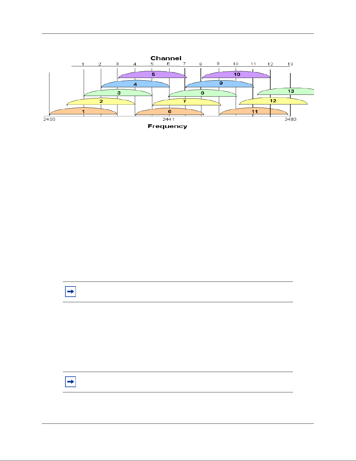
Figure 1 Frequencies used by each channel
• Wireless handset range – Wireless LAN coverage must be available wherever wireless
handsets will be used. Although the typical range for a wireless handset is comparable to
that of a laptop computer utilizing a wireless LAN PC card, the range may not be exactly
the same. Therefore, it is preferable to use a handset to carry out the site survey, if
possible. Remember that wireless handsets might be used in areas where data devices are
not typically used, such as stairwells, washrooms, hallways, and outdoor areas.
• Number of wireless handsets per AP – Estimate the number of wireless handsets and the
anticipated call volume per AP area to ensure that the maximum number of calls per AP
will not be exceeded. See Appendix B, “Compatible Access Points for the maximum
number of calls per AP for each supported manufacturer.
• The data rates at which the wireless handsets will operate – Higher data rates (such as
11Mb/s) can only be sustained while well within the range of the AP. If the wireless
handsets are operating near the limits of the radio frequency (RF) coverage from the AP,
they automatically drop to 1 Mb/s operation. Handsets require approximately:
— 7% of available bandwidth per call at 11 Mb/s operation
— 10% of the available bandwidth per call for 2 Mb/s operation
— 15% of the available bandwidth per call for 1 Mb/s operation
Chapter 3 Planning 25
Note: These requirements mean that areas with a high-use density must receive
RF coverage at the highest data rate of operation.
• LAN bandwidth – Estimate anticipated peak call volume to ensure that enough bandwidth
is available to handle the network traffic generated by all the wireless handsets. Handsets
require approximately 150 kbps of bandwidth per call. Network traffic can be monitored/
analyzed using a network sniffer or an SNMP workstation.
• Number of other wireless devices per AP – The wireless handsets can share bandwidth
with other wireless devices. To ensure adequate RF bandwidth availability, consider the
number of wireless data devices in use per AP.
Note: In a very large or complex site, it may be advisable to contract a
professional site survey.
WLAN IP Telephony Installation and Configuration Guide
Page 26

26 Chapter 3 Planning
Conducting an effective site survey
Consider the following points for an effective site survey.
Network usage
Examine the network usage:
• How many people will be using a wireless handset?
• What areas of the site require wireless handset access?
• How many hours each day will wireless handsets be in use?
• Which locations are likely to generate the largest amount of traffic?
• Where is future network expansion most likely?
Mobility requirements
Assess the mobility requirements:
• How many wireless handset users are in motion continually, such as in a warehouse or
hospital?
• How many users work from different fixed locations throughout the site?
Physical site study
Perform a study of the physical site:
• Study blueprints of the proposed site. A site blueprint provides a map of the site, including
the location of objects such as walls, partitions, and anything else that could affect the
performance of a wireless handset. This helps identify areas where wireless handsets are
less likely to perform well. Many obstructions are not readily visible and, in some cases, a
room originally built for a specific purpose, such as a radiology lab, might have been
converted into something completely different, such as a conference room. The blueprint
may also show areas proposed for future building expansion.
• Mark possible wireless handset usage locations on the blueprint and refer to the marked
blueprint during the physical walk-through and inventory.
Walk-through and survey
Conduct a physical walk-through and survey:
• Document any items or materials near a proposed AP location that might interfere with
reception or transmission and affect wireless handset performance, such as metal shelving.
• Document stock and inventory levels, current environmental conditions, and any materials
that may interfere with wireless handset transmissions.
NN40010-303NN40010-303
Page 27

Chapter 3 Planning 27
RF transmission testing
Once the APs have been installed and configured, it is necessary to measure the strength of the RF
transmissions. Signal strength testing ensures that all usage areas have adequate coverage. This can
be performed in two ways.
1 Use the handsets to determine AP signal strength using the Site Survey mode.
2 Use two portable computers with wireless hardware operating on a point-to-point basis. Using
diagnostic software provided by the AP vendor, a coverage area for a potential AP can be
determined by keeping one portable computer in one place and moving around with the other
computer. Check with the vendor as to what tools are provided and what approach is
recommended for deploying their APs.
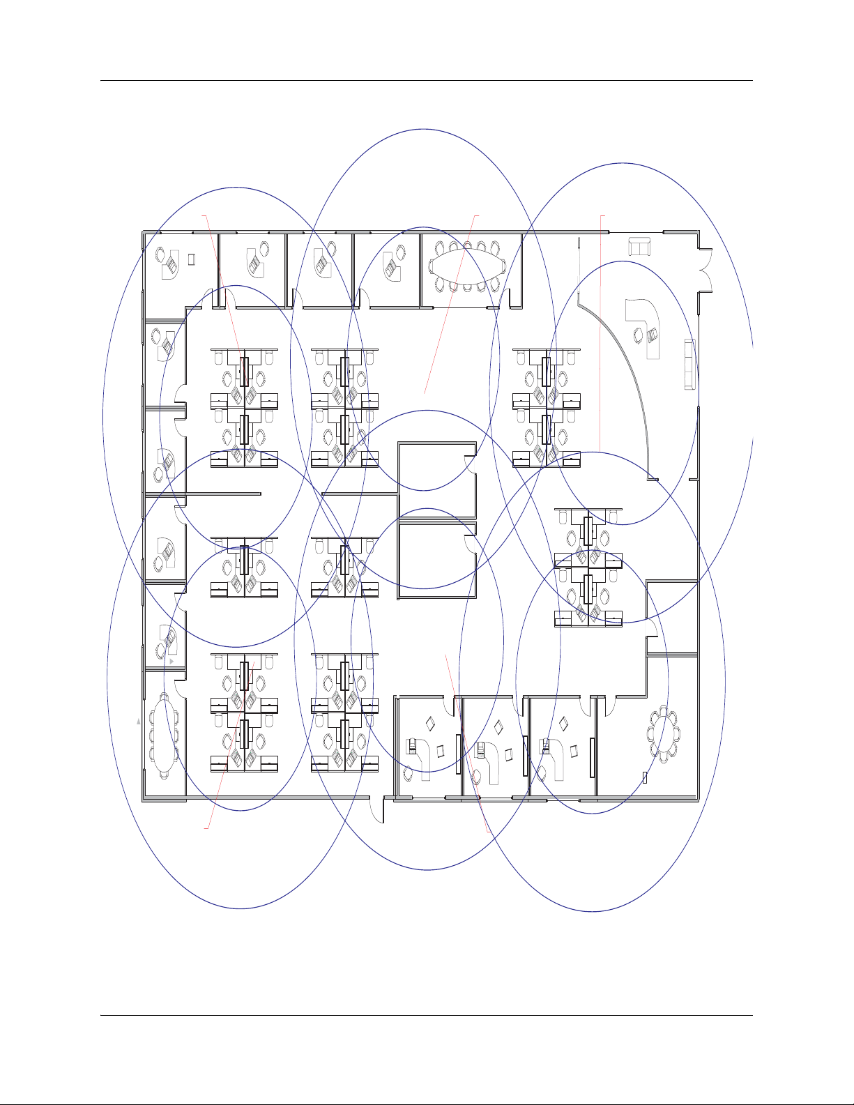
Example of AP placement
Figure 2 on page 28 is an example of an AP placement diagram.
WLAN IP Telephony Installation and Configuration Guide
Page 28
28 Chapter 3 Planning
Figure 2 Sample AP placement diagram
Cell “D” = Channel 1 w/11 Clients Cell “B” = Channel 6 w/15 Clients Cell “A” = Channel 1 w/9 Clients
Meeting Room
Reception
10'-0"
Training Room
18'-0"
Cell “E” = Channel 6 w/19 Clients
Men
Women
Cell “C” = Channel 11 w/6 Clients
Computer Room
Break Room
Microwave
802.11b Preliminary Wireless
Site Plan
NN40010-303NN40010-303
553-AAA1447
Page 29
Solving coverage issues
Resolve coverage issues by adding and/or relocating APs.
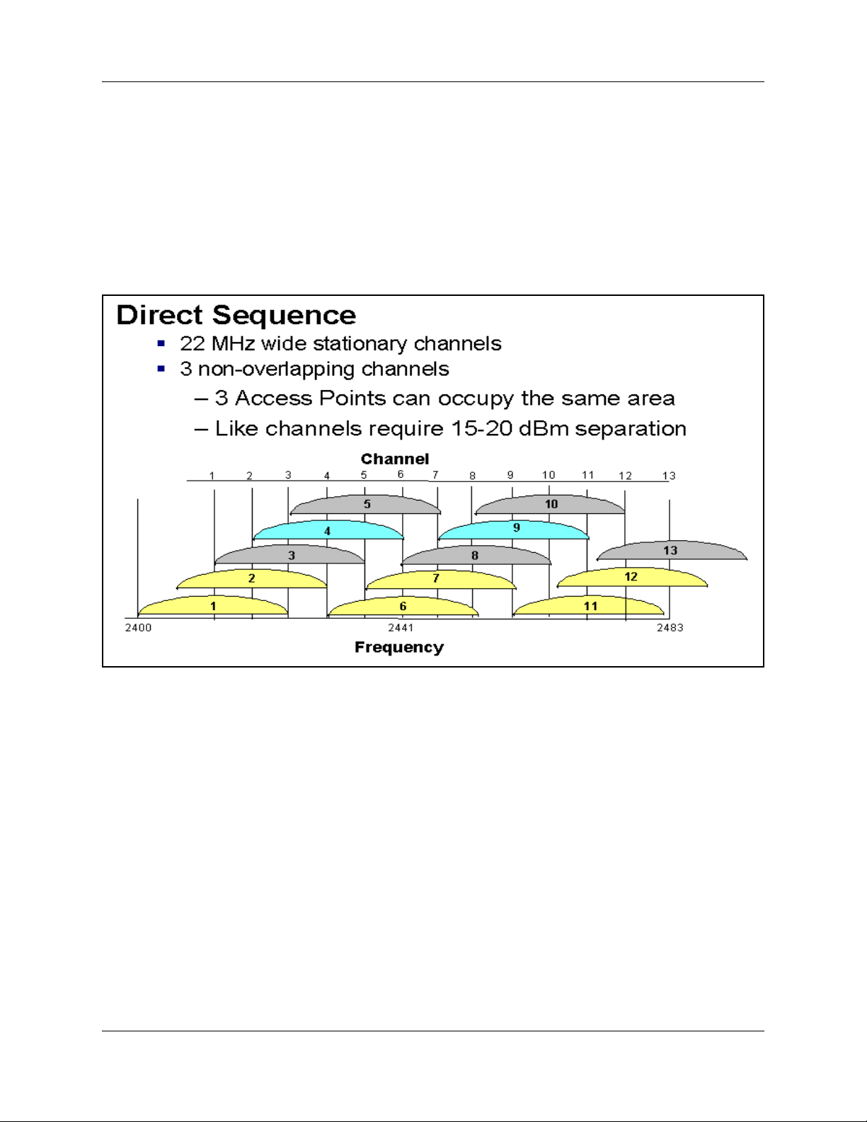
Solving overlap issues
Resolve overlap issues by reassigning channels to the APs or by relocating the APs. Like channels
require 15–20 dBm separation. See Figure 3.
Figure 3 jChannel assignment
Chapter 3 Planning 29
Refer to the AP vendor documentation for more information on overlap.
Network planning
It is necessary to ensure that all connections and interfaces for the IP Telephony network be
configured as full-duplex. Duplex mismatches anywhere on the WLAN can cause the wireless IP
Telephony system not to function normally.
Zones
Avaya recommends that the handsets be assigned to dedicated zones. The zones can be used to
manage the bandwidth of the WLAN IP Telephony Manager 2245 groups. As well, zone
designations can be used to list the wireless handsets that are currently registered or have been
registered using LD 117 commands.
For more information, see “Bandwidth management” on page 37.
WLAN IP Telephony Installation and Configuration Guide
Page 30
30 Chapter 3 Planning
WLAN IP Telephony Manager 2245 planning
Both the WLAN IP Telephony Manager 2245 and the WLAN Application Telephony Gateway
2246 are connected to the Ethernet switch.
Installation requirements
The WLAN IP Telephony Manager 2245 requires a CAT5 cable connection between its network
port and the Ethernet switch. The WLAN IP Telephony Manager 2245 auto-negotiates to the type
of port on the Ethernet switch. It supports 10BaseT, 100BaseT, full-duplex and half-duplex port
types.
Avaya recommends 100BaseT full-duplex.
Note: When multiple WLAN IP Telephony Managers 2245 are used, all the
WLAN IP Telephony Managers 2245 must use a uniform media type. Do not use
full-duplex on some and half-duplex on others, or 10BaseT on some and
100BaseT on others.
Capacities
Table 2 lists the number of wireless handsets supported for the different physical media used in the
network.
Table 2 Supported number of calls and wireless handsets
Media type Number of supported calls
10BaseT 10 500
100BaseT 80 500
In any subnet where wireless handsets will be used, each subnet must have one or more WLAN IP
Telephony Managers 2245. A WLAN IP Telephony Manager 2245 group on a subnet consists of
one or more WLAN IP Telephony Managers 2245 and their associated wireless handsets. Only
one master WLAN IP Telephony Manager 2245 can be on a subnet.
WLAN IP Telephony Manager 2245 groups
WLAN IP Telephony Manager 2245 groups are those that have more than one WLAN IP
Telephony Manager 2245 in order to accommodate larger systems and a higher volume of wireless
telephony traffic.
Number of supported
wireless handsets
NN40010-303NN40010-303
Page 31

Master WLAN IP Telephony Manager 2245
In a group comprised of multiple WLAN IP Telephony Managers 2245, a master WLAN IP
Telephony Manager 2245 must be identified and must be configured with a static IP address. The
wireless handsets and the other WLAN IP Telephony Managers 2245 locate the master by using
the master’s static IP address. The loss of a non-master WLAN IP Telephony Manager 2245 does
not significantly affect the operation of the remaining WLAN IP Telephony Managers 2245.
However, the loss of the master WLAN IP Telephony Manager 2245 results in a loss of all
communication between all the WLAN IP Telephony Managers 2245. This causes the loss of all
active calls, and wireless handsets cannot check in until communication with the master is
re-established.
Group capacities
Table 3 lists the capacities in a WLAN IP Telephony Manager 2245 group.
Table 3 Multiple WLAN IP Telephony Manager 2245 capacities
Chapter 3 Planning 31
Number of
WLAN IP
Telephony
Managers
2245
1 80 80 65 500 433 325
2 64 128 111 1000 740 ‘555
3 60 180 160 1500 1067 800
4 58 232 211 2000 1407 1055
5 57 285 262 2500 1747 1310
6 56 336 312 3000 2080 1560
7 56 392 367 3500 2447 1835
8 55 440 415 4000 2767 2075
9 55 495 469 4500 3127 2345
10 55 550 524 5000 3493 2620
11 55 605 578 5500 3853 2890
12 54 648 621 6000 4140 3105
Calls per
WLAN IP
Telephony
Manager
2245
Total
calls
Erlangs
Number of
wireless
handsets
10% use
Number of
wireless
handsets
15% use
Number of
wireless
handsets
20% use
13 54 702 674 6500 4493 3370
14 54 756 728 7000 4853 3640
15 54 810 782 7500 5213 3910
16 54 874 836 8000 5573 4180
WLAN IP Telephony Installation and Configuration Guide
Page 32

32 Chapter 3 Planning
Gateway and timing function
WLAN IP Telephony Managers 2245 provide both the connection, or gateway, to the Call Server
for the wireless handsets, and the timing function for active calls. This gateway function is
distributed across the WLAN IP Telephony Manager 2245 group.
The number of active WLAN IP Telephony Managers 2245 is determined dynamically. Whenever
a WLAN IP Telephony Manager 2245 is added to or removed from the system, the distribution of
timing function for active calls, as well as the gateway function, is affected.
Roaming and handover
Roaming is the ability of the wireless handset to go anywhere in the WLAN Extended Service Set
RF signal coverage area, and to make and receive calls. Handover is the ability of the wireless
handset to maintain an active call without interruption while moving within a WLAN ESS RF
signal coverage area of a WLAN. This means that the wireless handset hands over the WLAN RF
signal from AP to AP without interrupting the data stream.
APs on the same subnet
The handset can perform handover and roaming across SVP-compliant APs that reside on the
same subnet as the wireless handset and WLAN IP Telephony Manager 2245 group.
APs on different subnets using WSS
When used in conjunction with a WSS 2250/2270 and APs 2230 operating in Layer 3 mode, the
handsets can perform roaming and handover across APs 2230 on different subnets. The WSS 2270
operating in Layer 3 mode is on the same subnet as the WLAN IP Telephony Manager 2245
group. The WSS 2270 allows the wireless handset to retain its original IP address, whether the IP
address was configured statically or obtained by DHCP. This means that roaming and handover
can occur across APs 2230 placed on any subnet.
Note: The WSS 2270 must be running version 2.0.71.0 (or later) software.
Mobility across different subnets when using DHCP
If a WSS is not in use and the wireless handset IP address has been acquired through DHCP, the
wireless handset must be powered down and powered up when entering a new subnet. This
enables functionality of the wireless handset when entering the WLAN RF signal coverage area of
a different WLAN IP Telephony Manager 2245 group on a different subnet. After the wireless
handset establishes communication within the ESSID of the new WLAN, obtains another IP
address from the DHCP server, and checks in with the group master, normal functionality returns.
If the wireless handset is configured to use ESSID of the new WLAN, it automatically discovers
the ESSID of the APs operating in broadcast mode.
NN40010-303NN40010-303
Page 33

Chapter 3 Planning 33
Table 4 summarizes the capabilities.
Table 4 Roaming and handover capabilities summary
IP address WSS in use Roaming capability Handover capability
Static No No No
Static Ye s Ye s Yes
DHCP No Yes, if the wireless
handset is
power-cycled
between subnets.
DHCP Ye s Ye s Yes
No
Multicast
IP multicast addresses are used by the WLAN Handset 2211 Push-to-talk feature. This requires
that multicasting be enabled on the Layer 2 switch used by the defined group (WLAN IP
Telephony Manager 2245 master/slaves and wireless handsets).
Routers are typically configured with filters to prevent multicast traffic from flowing outside of
specific domains. The wireless LAN can be placed on a separate VLAN or subnet to reduce the
effects of broadcast and multicast traffic from devices in other network segments.
WLAN Application Gateway 2246 planning
The optional WLAN Application Gateway 2246 requires a 10 Mb/s half-duplex switched Ethernet
connection.
Installation requirements for the WLAN IP Telephony Manager 2245 and the WLAN Application Gateway 2246
Locate the WLAN IP Telephony Manager 2245 and optional WLAN Application Gateway 2246 in
a space with:
• sufficient backboard mounting space and proximity to the LAN access device (switched
Ethernet switch), Call Server, and power source
• rack-mount unit (if using)
• easy access to the front panel, which is used for cabling
• for the WLAN Application Telephony Gateway 2246, a maximum distance of 325 feet
(100 meters) from the Ethernet switch
• for the WLAN IP Telephony Manager 2245, a maximum distance of 325 feet (100 meters)
from the Ethernet switch
WLAN IP Telephony Installation and Configuration Guide
Page 34

34 Chapter 3 Planning
IP address planning
The WLAN IP Telephony Manager 2245, the optional WLAN Application Gateway 2246, and
each of the wireless handsets and APs associated with them, requires an IP address.
The master WLAN IP Telephony Manager 2245 must have an IP
address statically configured.
If using DHCP for the rest of the network, the DHCP Server must have
the static IP address of the master WLAN IP Telephony Manager 2245
configured on it. If using DNS, the DNS Server must have the static IP
address of the master WLAN IP Telephony Manager 2245 configured on
it.
The wireless handsets can be configured to use DHCP or can be assigned a static IP address. If
there is no DHCP Server, the system administrator must determine what IP addresses are to be
used for static addressing. As well, whether static IP addressing or DHCP is used, a pool of alias IP
addresses must be configured on the WLAN IP Telephony Manager for the use of the wireless
handsets. Ensure that the pool of alias IP addresses is reserved exclusively for the use of the
wireless handsets.
IMPORTANT!
See Chapter 6, “WLAN IP Telephony Manager 2245 configuration for information on configuring
a static IP address on a WLAN IP Telephony Manager 2245. See “Configuring the WLAN
Application Gateway 2246 IP address” on page 148 for information on configuring a static IP
address for a WLAN Application Gateway 2246. See Chapter 7, “WLAN Handset configuration
for information on configuring a static IP address on the handsets. Refer to the vendor-specific
documentation for information on assigning IP addresses to the APs.
Record the static IP address assignments and store them in a safe place.
IP addressing with DHCP
A pool of alias IP addresses must be configured on the WLAN IP Telephony Manager 2245 for the
use of the wireless handsets. The use of a 22-bit subnet mask provides IP addresses for
approximately 500 wireless handsets (1024 nodes). Allocate a pool of an equal number of IP
addresses on the DHCP server for the wireless handsets.
For example:
142.223.204.1 to 142.223.205.254 are allocated on the DHCP Server for the use of the wireless
handsets.
142.223.206.1 to 142.223.207.254 are configured on the WLAN IP Telephony Manager for IP
aliases for the wireless handsets.
Ensure that all these IP addresses are reserved on the DHCP Server for the use of the wireless
handsets and not assigned to any other device.
NN40010-303NN40010-303
Page 35

Planning worksheets
Complete this worksheet and the worksheet in Table 6 on page 36 before beginning the
installation.
Copy and complete this worksheet in Table 5 for each WLAN IP Telephony Manager 2245.
Obtain the necessary information from the network administrator.
Table 5 WLAN IP Telephony Manager 2245 planning worksheet
Unit number
IP address
Hostname
Subnet Mask
Default Gateway
Master WLAN IP Telephony
Manager 2245
TFTP Download Master
IP address
Chapter 3 Planning 35
Primary DNS Server
IP address
Secondary DNS Server
IP address
DNS Domain
WINS Server IP address
Workgroup name
Syslog Server IP address
First alias IP address
Last alias IP address
WLAN IP Telephony Installation and Configuration Guide
Page 36

36 Chapter 3 Planning
Copy and complete this worksheet in Table 6 to maintain a configuration record for the handsets.
Table 6 Wireless handset planning worksheet
Line * MAC Address * User Name
1
2
3
4
5
6
7
8
9
Dialing
Ext.
IP Address
(if statically
configured)
10
11
12
13
14
15
16
17
18
* – required only if using the optional WLAN Application Gateway 2246.
NN40010-303NN40010-303
Page 37

Chapter 4
System information
Bandwidth management
Bandwidth management using bandwidth zones applies to the handsets.
Zones
A WLAN IP Telephony Manager 2245 group consists of a master WLAN IP Telephony Manager
2245, zero to 15 WLAN IP Telephony Manager 2245 slaves, and their associated wireless
handsets.
It is good practice to create a Bandwidth Management Zone for each WLAN IP Telephony
Manager 2245 group (one group per subnet) in LD 117. Use the CHG ZDES command to name
the zone with the IP address of the master WLAN IP Telephony Manager 2245.
37
=> NEW ZONE <zone number>
=> CHG ZDES <zone number> <Wnnn.nnn.nnn.nnn>
where W indicates “WLAN IP Telephony Manager 2245” and nnn.nnn.nnn.nnn is the IP address
of the master WLAN IP Telephony Manager 2245.
=> PRT ZDES ALL
This allows the system administrator or support personnel to print a list of the IP addresses of all
the master WLAN IP Telephony Managers 2245 in the system simply by printing the Zone
designators in LD 117. They are printed as Wnnn.nnn.nnn.nnn. This enables support personnel to
easily obtain the IP address of a WLAN IP Telephony Manager 2245 so they can telnet to the
WLAN IP Telephony Manager 2245 in order to diagnose and correct problems.
Zones for wireless handsets
Assign the virtual line TNs for the wireless handsets (configured in LD 11) to the zone number
assigned to its home WLAN IP Telephony Manager 2245 group. Using LD 117, this enables
support personnel to list the current registration status of all wireless handsets that belong to the
zone of a specific WLAN IP Telephony Manager 2245 group.
=> STIP ZONE <zone number>
All wireless handsets currently registered (checked in) with their home WLAN IP Telephony
Manager 2245 group will be listed. The format of the list is TERMIP = <alias IP address>, which
is located in the same subnet as the IP address of the master WLAN IP Telephony Manager 2245
of the group. Any wireless handsets that are currently checked in with another WLAN IP
Telephony Manager 2245 group are listed with a TERMIP in a different subnet from that of their
home WLAN IP Telephony Manager 2245 group ZDES.
WLAN IP Telephony Installation and Configuration Guide
Page 38

38 Chapter 4 System information
Current registration status of wireless handsets
To list the current registration status of all wireless handsets that are registered in a specific subnet,
regardless of their home zone, use either of the following LD 117 commands.
STIP TERMIP <subnet of the WLAN IP Telephony Manager 2245 group>
or
PRT IPDN <subnet of the WLAN IP Telephony Manager 2245 group>
Alias IP address
Using the DN of a wireless handset, support personnel can obtain the current or most recent alias
IP address used by a wireless handset when it checked in with the master of a WLAN IP
Telephony Manager 2245 group, and subsequently registered with the LTPS and Call Server.
=> PRT DNIP <DN of wireless handset>
Designating wireless telephone types
Unless there is another preferred use for the DES (Designator) prompt in LD 11, Avaya
recommends using the DES prompt to indicate the type of WLAN Handset — either type 2210,
2211, or 2212 — for the i2004 type of virtual line TN. This allows support personnel to enter
2210, 2211, or 2212 at the LD 20 DES prompt and receive a list of handsets that are configured on
the Call Server.
Call blocking
The WLAN IP Telephony Manager 2245 controls the media stream and blocks calls due to
bandwidth constraints on any AP without notifying the Call Server.
• The WLAN IP Telephony Manager 2245 can be configured with the maximum number of
simultaneous calls allowed on a single AP.
• On an incoming call for a wireless handset associated with a full AP, the caller hears
ringback and the Call Forward No Answer (CFNA) treatment is applied, such as
forwarding the call to voicemail. The called party is not notified of the incoming call.
• If the call originates from a wireless handset that is on a
bandwidth-restricted AP, the caller hears a warning tone and the call is blocked.
• If a wireless handset moves into an area serviced by an AP that is already at capacity, the
wireless handset will not associate with the new AP. Instead, the wireless handset attempts
to remain associated with an AP that has sufficient bandwidth. This could result in packet
loss, degraded signal and voice quality, and a call could be dropped.
• UNIStim signaling, such as watchdog updates or lamp audit, are not affected by the
bandwidth constraint.
NN40010-303NN40010-303
Page 39

Codecs
G.711, G.729A, and G.729B codecs are supported. The RTP packets that transit between the
wireless handsets and the WLAN IP Telephony Manager 2245 always contain 30 msec of voice.
The WLAN IP Telephony Manager 2245 repackages the voice data to the correct packet size. The
jitter buffer is always configured to 70 msec, and any UNIStim messages that configure the jitter
buffer are ignored.
If it is necessary for the IP Phone to use a codec that is not supported on the wireless handsets,
such as G.723.1, then the wireless handsets must be configured on their own separate node.
If a remote endpoint is configured for G.723.1 as the Bbest Bandwidth (BB) Codec and G.711 as
the Best Quality (BQ) Codec, (G.729 is not configured), the media path negotiates to G.711. The
result may be unexpected consequences on a narrow-band link.
Chapter 4 System information 39
IMPORTANT!
If the wireless handset is registered to the same LTPS as the IP Phones,
then configure only the subset of codecs supported by both the wireless
handsets and the IP Phones.
Jitter buffer
The handsets do not support a configurable jitter buffer. If they receive the “Jitter Buffer
Configuration” UNIStim message, the command is ignored. The jitter buffer is fixed at 70 msec.
There are two implications of a fixed jitter buffer setting:
• If the system jitter buffer setting is less than 70 msec (default is 50 msec), there is a
slightly longer delay in the IP Phone receive direction.
• If the system jitter buffer setting is longer than 70 msec to accommodate severe network
jitter, there could be slightly higher packet loss in the IP Phone receive direction.
The longer than normal jitter buffer setting is reasonable since extra jitter is introduced by the RF
portion of the link.
RLR and SLR
The handsets do not support UNIStim messages used to adjust the Receive Loudness Rating
(RLR) and Send Loudness Rating (SLR) of the wireless handset.
RTCP
Handsets do not support Real-time Transport Control Protocol (RTCP). Incoming RTCP packets
sent to the wireless handsets are actually sent to the WLAN IP Telephony Manager 2245 and are
discarded. If the wireless handset is queried for RTCP parameters, the wireless handset returns
dummy values of 0 jitter, 0 latency, and 0 packet loss.
WLAN IP Telephony Installation and Configuration Guide
Page 40

40 Chapter 4 System information
Gain adjustment
The handsets ignore any UNIStim messages that adjust the loss plan of the wireless handset.
Programmable rings and tones
The wireless handsets support alerting cadences but only a single alerting frequency.
The wireless handsets have the same call progress tone capability as the existing IP Phones 2004.
In/Out of Service tones
When the handset completes registration with the Call Server, it plays the “In Service” tone. When
the handset loses connection with the Call Server and re-sets, it plays the “Out of Service” tone.
Local mode display
Because the default state of the wireless handset is Standby, it is only possible to determine if the
wireless handset is in Local mode by pressing the off-hook (Green) or the MENU keys. Pressing
these keys changes the state of the handset to Active Idle or Active Off-Hook, therefore putting it
in communication with the primary Signaling Server.
For the MG 1000B, if a wireless handset is registered to the Small System Controller (SSC) in
Local mode, then the local-mode license information is displayed on the wireless handset on the
second line of the display. Since the maximum number of display characters on the wireless
handset is 19 characters, the local-mode license information on the wireless handset display is
truncated. See Table 7.
Table 7 IP Phone 2004 and handset Local mode license display (MG 1000B only)
IP Phone 2004 Handset
Licensed days left x Licensed days lft x
Licensed days left xx Licensed ds lft xx
Beyond licensed period Beyond licensd prd
NN40010-303NN40010-303
Page 41

Survivable Remote Gateway
The handset can be deployed in a Survivable Remote Gateway (SRG) configuration for both SRG
1.0 and SRG50.
Test Local mode is not accessible because the Services key is not supported in Local mode.
The navigation keys are supported in Normal mode and not in Local mode.
Since the default state of the wireless handset is Standby, it is only possible to determine if the
wireless handset is in Local mode by pressing the off-hook (Green) or MENU keys. Pressing these
keys changes the state of the handset to Active Idle or Active Off-Hook, therefore putting it in
communication with the primary Signaling Server in the main office.
Note: In order to allow SRG 1.0 systems based on BCM 3.6, to correctly operate
with the handsets, they must have a software patch installed. The patch can be
downloaded from the Avaya Electronic Software Delivery web site.
The BCM/SRG 3.6 WLAN IP Telephony Feature patch is called
BCM_360[1].039__WLAN_IP_Telephony_Patch.exe, which includes 51 files
required for automated patch installation.
Chapter 4 System information 41
Note: No patch is required for SRG 1.0 based on BCM 3.7 or SRG50 systems
External Applications Server
The External Applications Server (XAS) applications are not available on the handsets.
End-to-end QoS
End-to-end QoS, such as DiffServ, and Layer 2 QoS, such as 802.1 Q/p, are not supported on the
wireless telephone system. Any UNIStim commands sent to the wireless handsets attempting to
adjust Layer 2 or Layer 3 QoS parameters are ignored. In addition, the WLAN IP Telephony
Manager 2245 does not support any Layer 2 or Layer 3 QoS mechanisms.
However, it is possible to provide QoS mechanisms through configuration of network equipment.
The Layer 2 switch port to which the WLAN IP Telephony Manager 2245 is connected can be
configured to add 802.1 Q/p tagging. The Layer 3 port that acts as the gateway for the WLAN IP
Telephony Manager 2245 can be configured to add the appropriate DiffServ tagging. Since all of
the signaling and media traffic passes through the WLAN IP Telephony Manager 2245, all packets
are tagged with the appropriate priority. If more than one WLAN IP Telephony Manager 2245 is
used, each Layer 2 port to which a WLAN IP Telephony Manager 2245 is connected must be
configured to add the 802.1 Q/p tagging.
WLAN IP Telephony Installation and Configuration Guide
Page 42

42 Chapter 4 System information
NAT
Handsets can be deployed in an Network Address Translation (NAT) environment.
This section describes important considerations that must be taken into account when using the
handsets in a NAT environment. Failure to comply with or heed these considerations can result in
wireless handset malfunction.
For detailed information on NAT and the NAT Traversal feature, refer to IP Line: Description,
Installation, and Operation (553-3001-365).
NAT Traversal feature
The NAT Traversal feature is used where the IP Phone (this includes the handsets) is located on
the private side of the NAT router, while the rest of the Server resides on the public side.
To ensure correct deployment of the wireless handsets in this type of network configuration, most,
if not all, of the WLAN equipment should reside on the private side of the NAT router.
Network configurations
The following sections describe the different WLAN devices and how they must be deployed in
the NAT environment.
The handsets can be deployed behind a NAT router with no Security Switch, as shown in Figure 4
on page 43. Figure 4 includes a Layer 2 switch. This can be any Layer 2 switch (for example,
Ethernet Switch 450). No Layer 3 device, such as a router, can be located between the wireless
handsets and the WLAN IP Telephony Manager 2245.
NN40010-303NN40010-303
Page 43

Chapter 4 System information 43
Figure 4 NAT network configuration 1 – without a security switch
Note: If the WLAN IP Telephony Manager 2245 is not in the same subnet as the
handsets, the handsets do not work.
If network security is a concern, a Wireless Security Switch can be included in the network
configuration, as shown in Figure 5 on page 44. Examples of Wireless Security Switches are
Wireless Security Switch 2250, 2270 or the Contivity product line.
Note: In both Figure 4 and Figure 5, the cloud can represent a corporate intranet or the
public internet.
WLAN IP Telephony Installation and Configuration Guide
Page 44

44 Chapter 4 System information
Figure 5 NAT network configuration 2 – with a security switch
WLAN IP Telephony Manager 2245 in a NAT environment
The IP Telephony Manager 2245 must be in constant communication with the handsets to ensure
handset functionality. Since the IP Telephony Manager 2245 must be on the same subnet as the
handsets, the IP Telephony Manager 2245 must be located on the private side of the NAT router.
The wireless VoIP network does not function if the IP Telephony Manager 2245 is located on the
public side of the NAT router.
Port 10000 is used for bi-directional UDP traffic between the IP Telephony Manager 2245’s
handset alias IP addresses and the Echo Server on the TPS used for NAT detection. Any network
security devices that monitor network traffic between the IP Telephony Manager 2245 and the
Signaling Server(s) must be configured to allow traffic using port 10000 to pass freely between
these devices.
NN40010-303NN40010-303
Page 45

Chapter 4 System information 45
Wireless Access Point 2230/2270 in a NAT Environment
If Wireless Access Points (WAP) 2230 or 2231 are used, a Wireless Security Switch 2270 must
also be configured to control the WAP 2230/2231. Both the WAPs and the Wireless Security
Switch must be located behind the NAT router (on the private side). The Wireless Security Switch
2270 cannot communicate with the WAPs if a NAT router is on the public side.
If non-Avaya WAPs are used, they must be also located on the private side. See Appendix B,
“Compatible Access Points for a list of supported
third-party APs.
DHCP Server location in a NAT environment
The WLAN Handsets only support Full DHCP. The device acting as a DHCP Server to the WLAN
Handsets must be configurable to send the vendor-specific DHCP fields.
In some cases, the NAT router acts as the DHCP Server. In this case, then configure the NAT
router with the required DHCP parameters and necessary information.
If a separate DHCP Server is used, it must be located on the private side of the network. See
Figure 6 on page 45 for more information.
Figure 6 Network configuration 3 – with Full DHCP Server
WLAN IP Telephony Installation and Configuration Guide
Page 46

46 Chapter 4 System information
TFTP Server location in a NAT environment
The TFTP Server can be located on the public side of the network. In this case, the NAT router
(and Wireless Security Switch if deployed) may have to be configured to allow WLAN Handsets
access to the TFTP Server (allow traffic through on the required ports). This scenario is
represented in Figure 6 on page 45.
Another option is to place the TFTP Server on the private side of the network.
WLAN Application Gateway 2246 in a NAT environment
If a WLAN Application Gateway 2246 is to be deployed, the requirements are similar to that of the
TFTP server.
The WLAN Application Gateway 2246 can be located on the public side of the network as long as
traffic is allowed on the correct ports. This scenario is represented in Figure 6 on page 45.
Alternatively, the WLAN Application Gateway 2246 can be placed on the private side of the
network.
CS 1000 and Meridian 1 features
Nearly all CS 1000 and Meridian 1 features are supported on the wireless telephone system.
Partially supported features are listed in Table 8. The features that are not supported are listed in
Table 9.
Table 8 Partially supported CS 1000 and Meridian 1 features
Feature Feature full name Description
DIG Dial Intercom Group Handsfree call option is not supported.
HOT I Intercom Hotline Voice Intercom Hotline (default) is not
supported. The Ringing option is
supported.
RGA Ring Again Since the handsets cannot buzz, there is
no Ring Again tone. The only way to use
the Ring Again feature is to determine if
the Ring Again indicator is flashing, which
is possible only when the wireless
handset is in the active state.
.
Table 9 CS 1000 and Meridian 1 features not supported
Feature Feature full name Description
AAB Automatic Answerback Cannot automatically enable Handsfree.
VCC Voice Call Cannot automatically enable Handsfree.
Active Call Failover Not supported.
NN40010-303NN40010-303
Page 47

IP Phone 2004 features
Table 10 provides information on the IP Phone 2004 features for the handsets.
Table 10 IP Phone 2004 features
Supported on the
Feature
Keypad Ye s
Navigation keys Ye s Up — Volume Up button
6 feature keys Ye s
4 soft-labelled keys Ye s
Display Partially IP phone 2004: 5x24 display
handsets Description
Down — Volume Down button
Left — button
Right — button
Handsets: 4x19 display
Chapter 4 System information 47
Message Waiting
Indicator
Branch Office Ye s
Survivable Remote
Gateway
Virtual Office Partially No “Services” key.
XAS No No “Expand” key.
Personal Directory
Callers List
Redial List
Password Admin No The handsets can be password-protected,
KEM No
Ye s Small envelope icon (l) in the top right of
the handset LCD display
Ye s
Use FCN+7 for the Services key to
support Virtual Office.
Ye s
but this is different from the IP Phone
2004 password protection mechanism.
The IP Phone 2004 password protection
is supported, in addition to the handset
password protection.
WLAN IP Telephony Installation and Configuration Guide
Page 48

48 Chapter 4 System information
NN40010-303NN40010-303
Page 49

Chapter 5
Installation
Required materials
The following equipment must be provided by the customer:
• power outlet(s) – must accept the provided AC adapter, one for the WLAN IP Telephony
Manager 2245 and one for the WLAN Application Gateway 2246 (if used).
• plywood backboard space – the WLAN IP Telephony Manager 2245 is designed to be
wall-mounted to ¾” plywood securely screwed to the wall.
or
optional WLAN IP Telephony Manager 2245 rack-mount kit (must be ordered separately),
containing mounting plates and screws
• screws – used to mount the WLAN IP Telephony Manager 2245 to the wall. Four #8 - ¾”
panhead wood screws (or similar devices) are required.
• 10BaseT CAT5 cable with an RJ-45 connector for the optional WLAN Application
Gateway 2246 – provides a connection to the Ethernet switch.
• CAT5 cable with an RJ-45 connector for the WLAN IP Telephony Manager 2245 –
provides a connection to the Ethernet switch.
• DB-9 female null-modem cable – required for initial configuration of the WLAN IP
Telephony Manager 2245 and WLAN Application Gateway 2246.
49
Supplied equipment
Each WLAN IP Telephony Manager 2245 and WLAN Application Gateway 2246 is shipped with
one Class II AC adapter with 24V DC, 1A output.
Pre-installation checklist
Ensure that the following requirements have been met prior to installation:
• The location chosen for the WLAN IP Telephony Manager 2245 and WLAN Application
Gateway 2246 is adequate and power is available.
• APs are SVP-compatible and coverage is adequate.
• A dedicated line is available for remote modem access, if needed.
• The telephone system administrator is on-site to program the existing telephone system.
WLAN IP Telephony Installation and Configuration Guide
Page 50

50 Chapter 5 Installation
Installing the WLAN IP Telephony Manager 2245
The following are the tasks that must be completed to install the WLAN IP Telephony Manager
2245:
1 “Wall mounting” on page 51.
or
“Rack-mounting” on page 51.
2 “Connecting to the LAN” on page 52.
3 “Connecting to the power” on page 52.
About the front panel
The front panel of the WLAN IP Telephony Manager 2245 contains ports to connect to the
following:
•power
•LAN
• administrative computer through an RS-232 port
Status LEDs supply information about the WLAN IP Telephony Manager 2245’s status and
activity. See Figure 7.
Figure 7 WLAN IP Telephony Manager 2245 front panel
• RS-232 port – the male DB-9 connector (DTE). Provides an RS-232 connection to a
terminal, terminal emulator, or modem for system administration.
•Link LEDs
— LNKOK – lit when there is a network connection
— ACT – lit when there is system activity
— COL – lit if there are network collisions
• NETWORK – connects the WLAN IP Telephony Manager 2245 to the wired Ethernet
LAN
• ERROR LED – lit when the system has detected an error
NN40010-303NN40010-303
Page 51

Chapter 5 Installation 51
• Status LEDs – indicate system error messages and status
— 1 – heartbeat
— 2 – active calls
— 3, 4, 5 – currently unused
• PWR – connects to the AC adapter supplying power to the system
WAR NING
Use only the provided Class II AC adapter with 24V DC,
1A output.
Wall mounting
The WLAN IP Telephony Manager 2245 can be mounted either vertically or horizontally.
To wall-mount the WLAN IP Telephony Manager 2245
1 Use a 1/8-inch drill bit to drill four pilot holes, on 1.84 by 12.1 inch centers (approximately
equivalent to 1-13/16 inch by 12-1/8 inch).
2 Insert the #8 x 3/4-inch screws in the pilot holes and tighten, leaving a
1/8 to 1/4-inch gap from the wall.
3 Slide the WLAN IP Telephony Manager 2245 over the screws until the WLAN IP Telephony
Manager 2245 drops into place in the keyhole openings of the flange.
4 Tighten screws fully.
Rack-mounting
The rack-mount kit is designed for mounting the WLAN IP Telephony Manager 2245 in a standard
19-inch rack and contains the following equipment:
• Mounting plates – two for each WLAN IP Telephony Manager 2245 to be mounted.
• Screws – four rack-mount screws for each WLAN IP Telephony Manager 2245 to be
mounted.
WLAN IP Telephony Installation and Configuration Guide
Page 52

52 Chapter 5 Installation
To rack-mount the WLAN IP Telephony Manager 2245
1 Remove the corner screws from the WLAN IP Telephony Manager 2245.
2 Screw the U-shaped end (round screw holes) of the two mounting plates to the WLAN IP
Telephony Manager 2245.
3 Screw the other end of the two mounting plates (oblong screw holes) to the rack.
4 Repeat steps 1-3 for each additional WLAN IP Telephony Manager 2245. The mounting plate
is designed to provide the correct minimum spacing between units. When mounting multiple
units, stack the units in the rack as closely as possible.
Connecting to the LAN
Use an RJ-45 cable to connect the NETWORK port on the WLAN IP Telephony Manager 2245 to
the connecting port on the Ethernet switch.
Connecting to the power
Follow the steps in the following procedure to connect the power to the WLAN IP Telephony
Manager 2245.
To connect the power
1 Connect the power plug from the AC adapter to the jack labeled PWR on the WLAN IP
Telephony Manager 2245.
WAR NING
Use only the provided Class II AC adapter with output
24V DC, 1A.
2 Plug the AC adapter into a 110V AC outlet to supply power to the WLAN IP Telephony
Manager 2245.
The system cycles through diagnostic testing and the LEDs blink for approximately one
minute.
3 When the system is ready for use, verify the following:
a ERROR LED is off.
b Status 1 is blinking.
Installing the WLAN Application Gateway 2246
For information on installing the optional WLAN Application Gateway 2246, see Appendix A,
“WLAN Application Gateway 2246.
NN40010-303NN40010-303
Page 53

Chapter 6
WLAN IP Telephony Manager 2245 configuration
The WLAN IP Telephony Manager 2245 acts as a proxy for the wireless handsets and provides
several services for them. It is connected to the same subnet as the wireless handsets. The wireless
handsets always communicate voice and signaling directly with the WLAN IP Telephony
Manager 2245, using the proprietary SVP protocol.
SVP is required for QoS because the current IEEE 802.11a/b/g wireless LAN standard provides no
mechanism for differentiating audio packets from data packets. This standard is undergoing
revision to version 802.11e to provide functionality in an industry standard similar to SVP,
therefore ensuring high-quality voice in a mixed-client environment.
Functional description
• The WLAN IP Telephony Manager 2245 provides the following services to the handsets:
• It acts as a proxy for every wireless handset; that is, all UNIStim signaling and RTP media
to/from the wireless handset pass through the WLAN IP Telephony Manager 2245. Except
for the initial DHCP and TFTP sessions, the wireless handsets only communicate with the
WLAN IP Telephony Manager 2245.
53
Each WLAN IP Telephony Manager 2245 is configured with an IP address with which all
of the wireless handsets communicate. In addition, each WLAN IP Telephony Manager
2245 is configured with a pool of IP addresses. When a wireless handset registers with a
WLAN IP Telephony Manager 2245, the wireless handset is assigned one of the IP
addresses from the pool. All communication between this WLAN IP Telephony Manager
2245 and other devices (TPS, IP Phones, gateways, and other wireless handsets) is always
done through its pool IP address. In this sense, the WLAN IP Telephony Manager 2245
acts as a NAT (Network Address Translation).
Note: The WLAN IP Telephony Manager 2245 has a single physical Ethernet
interface and MAC address; therefore, all of the IP addresses are mapped to a
single MAC address.
WLAN IP Telephony Installation and Configuration Guide
Page 54

54 Chapter 6 WLAN IP Telephony Manager 2245 configuration
• The WLAN IP Telephony Manager 2245 server tags/untags packets with the SVP header.
SVP packets have the protocol byte of the IP header set to 0x77. SVP-compliant APs use
this proprietary tagging to give priority to tagged packets. For UDP (UNIStim and RTP)
packets going from the wireless handset to the network, the WLAN IP Telephony
Manager 2245 replaces the SVP protocol number, 0x77, with the UDP number, 0x11. For
packets going from the network to the wireless handset, the protocol number is changed
from 0x11 to 0x77.
Because packets that traverse the network between the wireless handset and the WLAN IP
Telephony Manager 2245 are not standard IP packets (the packets use a non-standard
protocol number), there can be no Layer 3 routing in the path. Therefore, the wireless
handsets and WLAN IP Telephony Managers 2245 must be in the same logical subnet.
• RTP packets between the wireless telephone and the WLAN IP Telephony Manager 2245
always contain 30 ms worth of voice, no matter what has been configured on the Call
Server. The WLAN IP Telephony Manager 2245 repackages the RTP packets to conform
to the size that has been configured in the Call Server. This provides more efficient use of
the available Radio Frequency (RF) bandwidth at the expense of slightly increased jitter
and latency.
• The WLAN IP Telephony Manager 2245 is configured with a maximum allowable
number of simultaneous media streams on a single AP. The WLAN IP Telephony Manager
2245 keeps track of the number of media streams on each AP and blocks calls to/from a
wireless handset that would exceed the configured capacity. For more information on call
blocking, see “Call blocking” on page 38.
A keep-alive packet exchange runs between the wireless handset and the WLAN IP
Telephony Manager 2245 every 30 seconds. If the wireless handset detects that the WLAN
IP Telephony Manager 2245 is unreachable, the wireless handset resets itself and attempts
to re-establish a connection with the master WLAN IP Telephony Manager 2245.
Configuration tasks
To configure the WLAN IP Telephony Manager 2245
1 “Connecting to the WLAN IP Telephony Manager 2245” on page 55.
2 “Configuring the network” on page 57.
3 “Configuring the WLAN IP Telephony Manager 2245” on page 60.
4 “Changing the password” on page 63.
In the initial configuration of the WLAN IP Telephony Manager 2245, the IP addresses and the
maximum number of active calls per AP must be configured. Later, the IP address of the TFTP
Server where the software files are located and the hostname can be configured by Telnet.
NN40010-303NN40010-303
Page 55

Chapter 6 WLAN IP Telephony Manager 2245 configuration 55
Connecting to the WLAN IP Telephony Manager 2245
The initial connection to the WLAN IP Telephony Manager 2245 must be made through a serial
connection to establish the WLAN IP Telephony Manager 2245 IP address. After the IP address is
established, connection to the WLAN IP Telephony Manager 2245 can be done through the
network using Telnet.
Avaya recommends that the complete initial configuration be performed when the serial
connection is made.
Through a serial port
Follow the steps in Procedure to connect to the WLAN IP Telephony Manager 2245 through a
serial port.
To connect to the WLAN IP Telephony Manager 2245 through a
serial port
1 Using a DB-9 female, null-modem cable, connect the WLAN IP Telephony Manager 2245 to
the serial port of a terminal or PC.
2 Run a terminal emulation program (such as HyperTerminal), or use a VT-100 terminal with the
following configuration:
— Bits per second: 9600
— Data bits: 8
— Parity: None
— Stop bits: 1
— Flow control: None
Note: If using Windows 2000, Service Pack 2 must be installed to enable the use
of HyperTerminal.
3 Press Enter to display the login screen.
4 Enter the default login admin and the default password admin.
Note: The login name and password are case-sensitive.
The NetLink SVP-II System screen displays. See
WLAN IP Telephony Installation and Configuration Guide
Figure 8 on page 56.
Page 56

56 Chapter 6 WLAN IP Telephony Manager 2245 configuration
Through Telnet
The Telnet method of connection is used for routine maintenance of the WLAN IP Telephony
Manager 2245 for local and remote administration, depending on the network.
Note: Telnet can only be used after the WLAN IP Telephony Manager 2245
IP address is configured.
To connect to the WLAN IP Telephony Manager 2245 through
Telnet
1 Run a Telnet session to the IP address of the WLAN IP Telephony Manager 2245.
2 Enter the login and the password.
Note: The login name and password are case-sensitive.
The NetLink SVP-II System menu displays. See Figure 8 on page 56.
Figure 8 NetLink SVP-II System screen
NN40010-303NN40010-303
Page 57

The following menu choices are available:
• System Status – view software code version, error messages, and status of operation. See
“To view the software version” on page 113 and Chapter 9, “Troubleshooting.
• SVP-II Configuration – set the mode and reset the system. See “Configuring the WLAN
IP Telephony Manager 2245” on page 60.
• Network Configuration – set network configuration options, including IP addresses and
hostname. See “Configuring the network” on page 57.
• Change Password – change the password for WLAN IP Telephony Manager. See
“Changing the password” on page 63.
• Exit – exit the menu.
Configuring the network
Select Network Configuration on the NetLink SVP-II System screen to configure the IP address
and other network settings of the WLAN IP Telephony Manager 2245. An optional Hostname and
the IP address of TFTP Server containing the software update files are also configured here. The
Network Configuration screen is shown in Figure 9.
Chapter 6 WLAN IP Telephony Manager 2245 configuration 57
WLAN IP Telephony Installation and Configuration Guide
Page 58

58 Chapter 6 WLAN IP Telephony Manager 2245 configuration
Figure 9 Network Configuration screen
Configure the following fields with information provided by the network administrator:
• IP Address: – enter the complete IP address for the WLAN IP Telephony Manager 2245,
including digits and periods.
Note: If this WLAN IP Telephony Manager 2245 is the master, it must have a
static IP address configured. Do not use DHCP to assign the IP address of the
master WLAN IP Telephony Manager 2245. Other WLAN IP Telephony
Managers 2245 in a multiple WLAN IP Telephony Manager 2245 environment
can have their IP address assigned by DHCP.
Fore more information on the master WLAN IP Telephony Manager 2245, see “WLAN IP
Telephony Manager 2245 planning” on page 30.
• Hostname: – optional field. Change the default hostname of this WLAN IP Telephony
Manager 2245, if desired. Hostname is for identification purposes only.
Note: Spaces cannot be entered in this field.
• Subnet mask – the subnet mask of the subnet.
• Default Gateway – the default gateway for the subnet.
• SVP-II TFTP Download Master – the IP address of the TFTP Server where the software
update files are saved. Enter one of the following:
— NONE – disables this function
— IP address of the TFTP Server that transfers software updates to the WLAN IP
Telephony Manager 2245
NN40010-303NN40010-303
Page 59

Chapter 6 WLAN IP Telephony Manager 2245 configuration 59
• Primary DNS Server, Secondary DNS Server, DNS Domain – used to configure
Domain Name Services (DNS). Obtain the settings from the network administrator.
Optionally, enter DHCP. This enables the DHCP client in the WLAN IP Telephony
Manager 2245 to attempt to automatically obtain a valid IP address from the DHCP
Server. The DHCP setting is only valid when the IP address is obtained from DHCP.
• WINS Server – the IP address of the Windows Name Services (WINS) Server. Obtain the
settings from the network administrator.
Optionally, enter DHCP. This enables the DHCP client in the WLAN IP Telephony
Manager 2245 to attempt to automatically obtain a valid IP address from the DHCP
Server. The DHCP setting is only valid when the IP address is obtained from DHCP.
When WINS is configured, the WLAN IP Telephony Manager 2245 can translate
hostnames to IP addresses. This means that when using Telnet, the WLAN IP Telephony
Manager 2245 can be accessed using its hostname rather than its IP address.
• Syslog Server – the IP address of the server where the system logs for the WLAN IP
Telephony Manager 2245 are written. If a Syslog Server is configured, a message is sent to
the Syslog Server when an alarm is generated. Enter one of the following:
— NONE – disables this function
— IP address of the Syslog Server
• Maintenance Lock – indicates if the WLAN IP Telephony Manager 2245 is in
Maintenance Lock mode.
• SendAll – in a system with multiple WLAN IP Telephony Managers 2245, the SendAll
option is provided to speed configuration and ensure identical settings. The S=SendAll
option enables configuration parameters of the selected field to be sent to every WLAN IP
Telephony Manager 2245 on the LAN. SendAll can only be used after the IP address is
configured on each WLAN IP Telephony Manager 2245 using a serial connection. If
identical configuration parameters are to be used for all WLAN IP Telephony Managers
2245, configure only the IP address and custom hostname (if desired) on each WLAN IP
Telephony Manager 2245 using the initial serial connection. Then connect through the
LAN to this WLAN IP Telephony Manager 2245 and use SendAll to transmit identical
configuration options of each field for all WLAN IP Telephony Managers 2245.
IMPORTANT!
If SendAll is used on the system, all passwords must be identical. Do not
change the password at the initial configuration if the SendAll option will
be used. Use the default password and change it globally, if desired,
after a LAN connection is established for all WLAN IP Telephony 2245
units.
If independent administration of each WLAN IP Telephony Manager
2245 is desired, the passwords can be set during initial configuration.
WLAN IP Telephony Installation and Configuration Guide
Page 60

60 Chapter 6 WLAN IP Telephony Manager 2245 configuration
Saving the configuration
Reset the WLAN IP Telephony Manager 2245 in order to save the configuration parameters.
To save the configuration
1 Press Esc on the keyboard.
If the WLAN IP Telephony Manager 2245 is in Maintenance Lock, a prompt appears asking
if the configuration is to be saved.
2 Enter Y.
3 Alternatively, select the Reset option found in the SVP-II Configuration screen. Press Esc.
See “Configuring the WLAN IP Telephony Manager 2245” on page 60.
Changing the master IP address
To change the IP address of the master WLAN IP Telephony Manager 2245, change it in the
Network Configuration menu and reboot the system. Then alias IP addresses can be changed in
each of the other WLAN IP Telephony Managers 2245 without incurring an error.
Configuring the WLAN IP Telephony Manager 2245
The WLAN IP Telephony Manager 2245 is configured on the SVP-II Configuration screen where
the mode of the WLAN IP Telephony Manager 2245 is configured. This screen is also used to lock
the WLAN IP Telephony Manager 2245 for maintenance and reset the WLAN IP Telephony
Manager 2245 after maintenance.
The WLAN IP Telephony Manager 2245 automatically locks for maintenance if the IP address is
changed. When a Maintenance Lock occurs, the WLAN IP Telephony Manager 2245 must be
reset upon exit. All active calls are terminated during a reset.
Access the SVP-II Configuration screen from the NetLink SVP-II System menu. Scroll to SVP-II
Configuration and press Enter.
The SVP-II Configuration screen is shown in Figure 10 on page 61.
Perform the desired SVP-II configuration.
NN40010-303NN40010-303
Page 61

Chapter 6 WLAN IP Telephony Manager 2245 configuration 61
Figure 10 SVP-II Configuration screen
• Phones per AP – enter the number of simultaneous calls supported for the AP type. AP
specifications are described in Appendix B, “Compatible Access Points.
• 802.11 Rate – select Automatic to allow the wireless handset to determine its rate (up to
11Mb/s). Select 1MB/2MB to limit the transmission rate between the wireless handsets
and APs.
• SVP-II Master – the IP address of the master of the WLAN IP Telephony Manager 2245
group must be identified. Select one of the following identification options:
— Enter the IP address of the master of the WLAN IP Telephony Manager 2245 in each
WLAN IP Telephony Manager 2245 group. Include the periods used in the IP address.
—Enter DHCP. Ensure that the IP address of the master WLAN IP Telephony Manager
2245 has been configured in the DHCP server and configure the other WLAN IP
Telephony Managers 2245 to obtain the information from the DHCP server.
—Enter DNS. Ensure that the IP address of the master WLAN IP Telephony Manager
2245 has been configured in the DNS server and configure the other WLAN IP
Telephony Managers 2245 to retrieve this information from the DNS server.
• First Alias IP Address / Last Alias IP Address – enter the range of IP addresses that this
WLAN IP Telephony Manager 2245 can use when acting as a proxy for the wireless
handsets.
Note: All alias addresses must be on the same subnet as the WLAN IP Telephony
Manager 2245. The IP addresses cannot be duplicated on other subnets or WLAN
IP Telephony Managers 2245. There is no limit to the number of IP addresses that
can be assigned, but the capacity of each WLAN IP Telephony Manager 2245 is
500 wireless handsets.
• SVP-II Mode – select NetLink IP.
WLAN IP Telephony Installation and Configuration Guide
Page 62

62 Chapter 6 WLAN IP Telephony Manager 2245 configuration
• Ethernet link – select auto-negotiate unless there is a need to specify the link speed.
• System Locked – use this option to take the system down for maintenance. The default is
N (No). Select Y (Yes) to prevent any new calls from starting. Enter N to restore normal
operation.
• Maintenance Lock – the system automatically sets this option to Y (Yes) after certain
maintenance activities that require a reset are performed, such as changing the IP address.
Maintenance Lock prevents any new calls from starting. This option cannot be changed. It
is automatically set by the system. Reset the WLAN IP Telephony Manager 2245 at exit to
clear Maintenance Lock.
• Reset – if this option is selected, a prompt appears to reset the WLAN IP Telephony
Manager 2245 when exiting the SVP-II Configuration screen.
• Reset all SVP servers – if this option is selected, all WLAN IP Telephony Managers 2245
on the subnet are reset.
Note: Resetting the WLAN IP Telephony Manager 2245 terminates any calls in
progress.
NN40010-303NN40010-303
Page 63

Changing the password
Avaya recommends that the default password be changed. Follow the steps in Procedure to
change the default or existing password.
To change the password
1 Select Change Password from the NetLink SVP-II System menu.
The Change Password screen appears. See Figure 11.
Figure 11 Change Password screen
Chapter 6 WLAN IP Telephony Manager 2245 configuration 63
2 Enter the old password, enter the new password, and confirm the new password.
The password parameters are as follows:
• must be more than four characters in length
• first character must be a letter
• other characters can be a letter or a number
• dashes, spaces, and punctuation marks are not allowed (alphanumeric only)
WLAN IP Telephony Installation and Configuration Guide
Page 64

64 Chapter 6 WLAN IP Telephony Manager 2245 configuration
3 Select Set Password and press Enter. Alternatively, press the S key on the keyboard.
IMPORTANT!
Record the password and keep it in a safe place.
If the password is forgotten, contact Avaya Technical Support for
assistance.
Now it is necessary to configure the wireless handsets. See Chapter 7, “WLAN Handset
configuration.
NN40010-303NN40010-303
Page 65

Chapter 7
WLAN Handset configuration
Wireless handset configuration is performed after the WLAN IP Telephony Manager 2245 has
been installed and configured. The steps to configure a wireless handset must be performed for
each wireless handset. The configuration cradle, attached to a personal computer, automates the
configuration process.
System provisioning
Provision the handset on the Avaya BCM system in the same manner as an IP Phone 2004.
Configuration tasks
To enable the handsets to operate on the WLAN system, perform the following tasks:
65
1 Configure handset. See “Configuring the handset” on page 65 and “Configuration cradle” on
page 87.
2 Program the features on the wireless handset. See “Feature programming” on page 84.
3 Test the wireless handset. See “Testing the wireless handsets” on page 96
Note: The handsets require special configuration to enable them to communicate
with the optional WLAN Application Gateway 2246. Ensure that these settings
are correct. See “Opening and using the Admin menu on the handset” on page 66.
The configuration cradle is an accessory to the handsets. Use the configuration cradle to create and
save configuration snapshots, save the configuration from an already-programmed handset, and
write a saved configuration to a handset. For more information, see “Configuration cradle” on
page 87.
Configuring the handset
Configure the WLAN Handsets using:
• Configuration cradle
• Administration Menu on the handset
Configuring the handset using the configuration cradle
The configuration cradle and its software provide an automated method to configure multiple
handsets. A full description is found in “Configuration cradle” on page 87.
WLAN IP Telephony Installation and Configuration Guide
Page 66

66 Chapter 7 WLAN Handset configuration
Opening and using the Admin menu on the handset
The Admin menu contains configuration options that are stored locally on each wireless handset.
Every wireless handset is independent. If the default settings are not desired, the Admin options
must be configured in each separate wireless handset that requires different settings.
For a diagram of the handset, see Figure 13 on page 86.
Follow the steps in “To open and use the Admin menu on the wireless handset to open and use the
Admin menu on the wireless handset.
To open and use the Admin menu on the wireless handset
1 With the wireless handset powered OFF, simultaneously press and hold the Power On/Start
Call and Power Off/End Call keys.
2 Release the Power On/Start Call key, then release the Power Off/End Call key.
The first option on the Admin menu appears.
Note: If an Admin Password has been configured, the display requires its entry
before opening the Admin menu. If no password is configured, the display
proceeds directly into the Admin menu.
3 Press the Up, Down, and Select side buttons, and the softkeys on the wireless handset to scroll
through the menu options.
An asterisk (*) next to an option indicates that it is selected.
• Press the Up/Down buttons to display the previous/next menu items.
• Press the Select button to select the menu option or item.
• Alternatively, press the OK softkey to select the menu option or item.
• Press the Save softkey to save the entry.
• Press the Bksp key to backspace when editing the entry.
• Press the Up softkey to return to the previous menu level.
• Press Cncl to cancel the entry and return to the previous menu level.
• Press the Exit softkey to exit the menus.
NN40010-303NN40010-303
Page 67

Chapter 7 WLAN Handset configuration 67
To make an alphanumeric string entry
1 On the keypad, press the Select button to change the entry.
2 Press the number key of the desired letter.
The number displays.
3 Press the number key again to display the first letter associated with that key.
4 Press the key again to scroll through the letters associated with that key.
Example: if 2 is pressed repeatedly, 2, A, B, C, a, b, and c are displayed.
The following table shows which keys to use to enter non-numeric characters or other
characters not represented on the keypad.
To enter... Press
. - _! # $ % & ‘ ( ) , : ; / \ = @ ~ 1
Space 0
Q q 7
Z z 9
5 When the correct entry displays, press the right arrow to move to the next character. Repeat for
each digit/letter of the entry.
6 Press the Save softkey to save the entry and return to the menu.
7 Press the Exit softkey to abort and return to the menu without saving any changes.
Admin menu options
Table 11 on page 68 lists the Admin menu items. Detailed descriptions of each item follow the
table.
Note: The default settings are indicated with an asterisk (*).
Note: In the Transmit Power section, the 50 mW and 30 mW settings only appear
if the Regulatory Domain is set to None or 01.
WLAN IP Telephony Installation and Configuration Guide
Page 68

68 Chapter 7 WLAN Handset configuration
Table 11 Admin menu options
Admin menu
option 2nd level 3rd level 4th Level 5th Level
Phone Config License Option Set Current [List per
download]
Terminal Type I2004
OIA On/Off Enable OIA
Disable OIA
Push-to-Talk Allowed
Channels
Allow/Disallow *Allow PTT
Admin Password Enter PW Re-enter
*Channel 1
*Channel 2
*Channel 3
*Channel 4
*Channel 5
*Channel 6
*Channel 7
*Channel 8
Disallow PTT
Password
NN40010-303NN40010-303
Page 69

Chapter 7 WLAN Handset configuration 69
Table 11 Admin menu options
Admin menu
option 2nd level 3rd level 4th Level 5th Level
Network Config IP Addresses *Use DHCP
Static IP Phone IP
TFTP Server IP
Default Gateway
Subnet Mask
Syslog Server IP
SVP IP Addr
Svr1 Srvr 1 IP Addr
Srvr 1 Port
Srvr 2 IP Addr
Srvr 2 Port
OIA Server IP
ESSID *Learn Once
Learn Always
Static Entry
Security *None
WEP Authentication Open System
Cisco FSR Username
Shared Key
WEP On/Off
Key Information Default Key
Key Length
Key 1-4
Rotation Secret
Password
WLAN IP Telephony Installation and Configuration Guide
Page 70

70 Chapter 7 WLAN Handset configuration
Table 11 Admin menu options
Admin menu
option 2nd level 3rd level 4th Level 5th Level
Network Config
(continued)
Security
(continued)
WPA-PSK Passphrase
Direct Entry
WPA2-PSK Passphrase
Direct Entry
VPN VPN Server IP
VPN Client IP Static IP
Phase 1 –
ISAKMP
Phase 2 – ESP Auth. Hash
IKE Mode
Config
Mode
Authentication
Diffie-Hellman
Auth. Hash
Encryption
Local ID
Lifetime (sec)
Options
Network Config
(continued)
ESP
Encryption
Remote
Network
Lifetime (sec)
Reg. Domain:
none
Transmit Power *Maximum
50 mW
30 mW
20 mW
15 mW
10 mw
5 mW
(See Note)
NN40010-303NN40010-303
Page 71

Chapter 7 WLAN Handset configuration 71
Table 11 Admin menu options
Admin menu
option 2nd level 3rd level 4th Level 5th Level
Diagnostics Run Site Survey
Restore Defaults
License Option
License Option enables selection of the VoIP protocol that the site is licensed to download and
run. The UNIStim Protocol to use for the handsets is 010. Any other protocol causes the wireless
handset to malfunction.
After selecting the correct protocol for the site, Avaya recommends upgrading the software for the
wireless handsets.
Terminal Type
Select I2004. The Terminal type configures the wireless handset for the type of PBX in use. The
Avaya BCM requires the Terminal type setting to be I2004.
Diagnostics
Mode
Syslog Mode *Disabled
Diagnostics On
*Diagnostics
Off
Errors
Events
Full
OAI On/Off
The Open Application Interface (OAI) enables the wireless handset to connect with the optional
WLAN Application Gateway 2246. This device allows third-party computer applications to
display alphanumeric messages on the wireless handset display and take input from the wireless
handset keypad. See Appendix A, “WLAN Application Gateway 2246 for more information.
If a WLAN Application Gateway 2246 is installed in the system, OAI may be optionally enabled
in each wireless handset. Select whether the wireless handset should attempt to connect to the
WLAN Application Gateway 2246 by choosing either the Enable or Disable options in this menu.
If OAI is enabled, and a WLAN Application Gateway 2246 IP address is available to the wireless
handset (either through DHCP or Static IP configuration), then the wireless handset communicates
with the WLAN Application Gateway 2246 at power-on, and then periodically during the time the
wireless handset is powered on.
Note: If a WLAN Application Gateway 2246 is not installed at the site, disable
the OAI feature to preserve network bandwidth and battery life.
WLAN IP Telephony Installation and Configuration Guide
Page 72

72 Chapter 7 WLAN Handset configuration
Push-to-talk
All eight push-to-talk channels are allowed by default. The push-to-talk menu contains the
following options:
• Allowed Channels — toggle the status of any allowed channel, by scrolling to the channel to
be disallowed and pressing the Select button. Allowed channels are displayed with a star (*) in
the left column. Only the allowed channels will appear on the Standby menu, where they can
be enabled or disabled by the user.
• Allow/Disallow — enables or disables push-to-talk. Scroll to Disallow PPT and press the
Select button to disable push-to-talk.
Push-to-talk is available only on the WLAN Handset 2211.
Admin Password
The optional Admin Password controls access to the administration functions in the Admin menu
of the wireless handset. Configure the password in each wireless handset for which controlled
access is desired. Wireless handsets are shipped without any Admin password.
Data entry for the password uses the alphanumeric string entry technique. Type the password and
press the Save soft key. A confirmation prompt will appear. Type the password again and press the
Save soft key. If the passwords match, the Admin password has been configured.
Note: If this option is selected on a wireless handset that already has a configured
password, and the Exit
means that the wireless handset will not require an Admin password to access the Admin
menu.
Record the wireless handset Admin password and store it in a safe
place. If the password is lost or forgotten, contact Avaya Technical
Support.
softkey is pressed with no entry, the password is erased. This
IMPORTANT!
IP Addresses menu
There are three modes in which the wireless handset can operate: DHCP-enabled, Static IP or Svr1
(Server 1). Select the mode for operation from the IP Address menu:
• * Use DHCP — use Dynamic Host Configuration Protocol (DHCP) to assign an IP address
each time the wireless handset is turned on. If DHCP is enabled, the wireless handset also
receives all other IP address configurations from DHCP.
• Static IP — allows a fixed IP address to be manually configured. If this option is selected, the
wireless handset prompts for the IP addresses of each configurable network component. When
entering IP addresses, enter the digits only, including leading zeroes. No periods are required.
NN40010-303NN40010-303
Page 73

Chapter 7 WLAN Handset configuration 73
• Server1 (Srvr1) — allows the IP addresses and ports of the primary and secondary servers
and OIA server to be configured either statically or through DHCP.
Regardless of the mode in which the wireless handset is operating, the following components must
be configured:
• Phone IP — the IP address of the wireless handset. This is automatically assigned if DHCP is
used. If using Static IP configuration, obtain a unique IP address for each wireless handset
from the network administrator.
• SVP Server IP — the IP address of the master of the WLAN IP Telephony Manager 2245
group. If using Static IP configuration, this is simply the IP address of the WLAN IP
Telephony Manager 2245. The WLAN IP Telephony Manager 2245 must be statically
configured to have a permanent IP address. If DHCP is being used, the wireless handset will
try the following, in order: the DHCP option 151, then a DNS lookup of “SLNKSVP2” if the
DHCP options 6 (DNS Server) and 15 (Domain Name) are configured.
• Server 1 IP — the TLAN node IP address of the LTPS IP Telephony Node on the Call Server.
If the wireless handset is using static IP address configuration, enter the TLAN node IP
address of the LTPS IP Telephony Node on the Call Server. If the WLAN handset is using
DHCP, the DHCP server must be configured to provide the TLAN node IP address (and UDP
port number) of the LTPS IP Telephony Node on the Call Server using one of the following
DHCP options:
46, 128, 144, 157, 191, and 251.
• Server 1 Port — the UDP port number used by the wireless handset to contact the LTPS
Node Connect Service to request registration with the LTPS and the Call Server. If the
wireless handset is using static IP address configuration, enter port number 7000. If the
WLAN handset is using DHCP, the DHCP server must be configured to provide the TLAN
node IP address and UDP port number of the LTPS IP Telephony Node on the Call Server
using one of the following DHCP options:
46, 128, 144, 157, 191, and 251.
The following components can be configured optionally:
• TFTP Server IP — the IP address of the TFTP Server on the network that holds software
images for updating the wireless handsets. If this feature is configured (not set to 0.0.0.0 or
255.255.255.255), either through Static IP configuration, through using DHCP option 66
(TFTP Server), or the Boot server/next server (siaddr) field, the wireless handset checks for
different software each time it is powered on or comes back into range of the network. This
check takes only five to seven seconds and ensures that all wireless handsets in the network
are kept up-to-date with the same version of software.
Note: It does not matter if the software version on the TFTP Server is newer or
older; if the versions are different, the wireless handsets download the software
from the TFTP Server.
• OAI Server IP — the IP address of the WLAN Application Gateway 2246 (if using). If using
Static IP configuration, this is simply the IP address of the WLAN Application Gateway 2246.
If DHCP is being used, the wireless handset tries DHCP option 152.
WLAN IP Telephony Installation and Configuration Guide
Page 74

74 Chapter 7 WLAN Handset configuration
• Default Gateway and Subnet Mask — used to identify subnets when using a complex
network that includes routers. Both of these fields must be configured (not set to 0.0.0.0 or
255.255.255.255) to enable the wireless handset to contact any network components on a
different subnet. They can be configured using Static IP configuration or through DHCP
options 3 (Default Gateway) and 1 (Subnet Mask) respectively. Contact the network
administrator for the proper settings for the network.
Note: The wireless handsets cannot “roam” across subnets, since the wireless
handsets cannot change their IP address while operational. Ensure that all the APs
are attached to the same subnet for proper operation. The wireless handset can
change subnets if DHCP is enabled, and the wireless handset is powered off, then
back on, when within range of APs on the new subnet.
• Server 2 IP — the IP address of the secondary Avaya device. Currently, the wireless handset
does not make use of this information. If using Static IP configuration, this is simply the IP
address of the device. If DHCP is being used, the wireless handset tries to obtain the device’s
IP address and port information using the following DHCP options:
46, 128, 144, 157, 191, and 251.
• Server 2 Port — the port number used by the secondary Avaya device to communicate with
IP phones. Currently, the wireless handset does not make use of this information. If using
Static IP configuration, consult the device documentation for port numbers. If DHCP is being
used, the wireless handset tries to obtain the device’s IP address and port information using the
following DHCP options:
43, 128, 144, 157, 191, and 251.
• Syslog Server IP — the address of the syslog server. See “Diagnostic Tools” on page 97 for
more information.
ESSID
Select the option that enables the wireless handset to acquire APs with the correct ESSID
(Extended Service Set ID, or Extended SSID) each time it is turned on.
With regard to Automatic Learn options, Broadcast ESSID must be enabled in the APs for ESSID
learning to function (or contact the AP vendor for specifics). Overlapping wireless systems
complicate the use of ESSID learning, as the wireless handset in an overlapping area could receive
conflicting signals. If this is the situation at the site, use Static Entry or Learn Once in an area
without overlapping ESSIDs.
• * Learn Once — allows the wireless handset to scan all ESSIDs for a DHCP server and/or
TFTP Server. After either is found, the wireless handset retains the ESSID from whichever AP
it associates with at that point. When overlapping wireless systems exist, the Learn Once
feature allows the wireless handset to use only the ESSID established the first time at all
subsequent power-ons. This ESSID is retained by the wireless handset until the ESSID option
is reselected.
NN40010-303NN40010-303
Page 75

Chapter 7 WLAN Handset configuration 75
• Learn Always — allows the wireless handset to automatically learn the ESSID at each
power-on or loss of contact with the wireless LAN (out of range). This may be useful if the
wireless handset will be used at more than one site.
• Static Entry — if the APs do not accept broadcast ESSID, or if there are overlapping wireless
systems in use at the site, enter the correct ESSID manually.
Security
The following are the security options:
• * None — disables any 802.11 encryption or security authentication mechanisms.
• WEP (Wired Equivalent Privacy) — a wireless encryption protocol that encrypts data frames
on the wireless medium, providing greater security in the wireless network. If WEP
Encryption is required at this site, each wireless handset must be configured to correspond
with the encryption protocol set up in the APs. Select the entries from the following options to
enable the wireless handset to acquire the system.
Note: By default, WEP options are off. If WEP is desired, options must be
configured in the wireless handset that match those configured in the APs.
Note: Encryption codes are displayed as they are entered. For security reasons,
codes are not displayed when a user returns to the Admin menu Encryption
options.
Note: WEP can be set to “optional” at the AP if there are wireless devices in use
that do not have WEP capability. All wireless devices must be upgraded to WEP
capability for a fully secured WEP environment.
Note: WEP settings must match the AP settings.
• Set each of the following options to match exactly the settings in the APs:
• Authentication — select either Open System or Shared Key.
• WEP — select either WEP Off or WEP On.
• Key Information — scroll through the options.
— Default Key — enter the pre-shared key number specified for use by the wireless
handsets. This will be 1 through 4.
— Key Length — select either 40-bit or 128-bit depending on the key length specified
for use at this site.
WLAN IP Telephony Installation and Configuration Guide
Page 76

76 Chapter 7 WLAN Handset configuration
— Key 1-4 — scroll to the key option that corresponds to the Default Key that was
entered above. Press Select and enter the encryption key as a sequence of hexadecimal
characters. Use the 2 and 3 keys to access hexadecimal digits A-F; use softkeys to
advance to the next digit and backspace. For 40-bit keys, enter 10 digits; for 128-bit
keys, enter 26 digits. The display scrolls as needed.
— Rotation Secret — used for proprietary WEP key rotation if this feature is supported
in the system.
• Cisco FSR — to provide the highest level of security without compromising voice quality on
Cisco Aironet WLAN APs, the Fast Secure Roaming (FSR) mechanism has been
implemented. FSR is designed to minimize call interruptions for wireless handset users as they
roam throughout a facility. Existing Aironet 350, 1100, and 1200 APs may require a firmware
upgrade to support FSR. Cisco FSR requires advanced configuration of the Cisco APs in the
site. See the Cisco representative for detailed documentation on configuring the APs and other
required security services on the wired network. To configure Cisco FSR in the wireless
handset, enter a Radius Server username and password into each wireless handset.
— Username — enter a username that matches an entry on the Radius server. Usernames are
alphanumeric strings, and can be entered using the alphanumeric string entry technique.
— Password — enter the password that corresponds to this Username
• WPA-PSK — Wi-Fi Protected Access (WPA) using Pre-Shared Key (PSK) provides
enhanced security and can be used, if supported by the APs. Select one of the following
options:
— Passphrase — enter a passphrase. The passphrase can be from 1 to 63 ASCII characters
or 64 hexadecimal digits. Do not choose a simple word because password-cracking
programs can easily extract the key and gain illicit access to the system. See “Choosing a
passphrase” on page 78 for further information.
— Example: why2fear4WPA-is-DEPLOYED_HERE
— Direct Entry — enter a pre-shared key code (hexadecimal number).
.
NN40010-303NN40010-303
Note: Consult the Configuration Note for the installed APs, at http://
www.spectralink.com/service/manuals_config.html, for information on whether
WPA-PSK is recommended for the AP. Configure the recommended version on
the AP and configure the corresponding option on the Admin menu.
Note: WPA-PSK settings must match the AP settings.
Page 77

Chapter 7 WLAN Handset configuration 77
• WPA2-PSK — WPA2 with PSK provides enhanced security over WPA-PSK and can be
used, if supported by the APs. Select one of the following options:
— Passphrase — enter a passphrase. The passphrase can be from 1 to 63 ASCII characters
or 64 hexadecimal digits. Do not choose a simple word because password-cracking
programs can easily extract the key and gain illict access to the system. See “Choosing a
passphrase” on page 78 for further information.
— Example: why2fear4WPA2-is-DEPLOYED_HERE
— Direct Entry — enter a pre-shared key code (hexadecimal number).
Note: Consult the Configuration Note for the installed APs, at http://
www.spectralink.com/service/manuals_config.html, for information on whether
WPA-PSK is recommended for the AP. Configure the recommended version on
the AP and configure the corresponding option on the Admin menu.
Note: WPA-PSK settings must match the AP settings.
• VPN — selecting VPN for security requires that a secure tunnel be established for the transfer
of information. The data itself no longer needs to be encrypted because the VPN tunnel is
already encrypted. VPN security requires a number of configuration steps, and is easily
configured using the Configuration Cradle (see “Configuration cradle” on page 87 for more
information). VPN security is also closely tied with the VPN server configuration. Only the
WLAN Handset 2212 supports VPN security.
Note: The VPN server must support the handset configuration.
— VPN Server IP — the IP address of the VPN server on the public (unsecure) side of the
network.
— VPN Client IP — the IP address that appears to be part of the private (or secure) network
— Static IP — the address can be statically programmed in the handset, in which case it
must match the address assigned to the handset in the VPN server.
— IKE Mode Config — if the VPN server supports the ISAKMP Mode Configuration,
it can assign the IP address automatically.
— Phase 1 – ISAKMP — this is the first phase of the tunnel negotiation process. It
establishes a set of security parameters (the ISAKMP Security Association) that will be
used to encrypt the negotiation of the actual tunnel parameters in Phase 2. In essence,
Phase 1 protects Phase 2.
— Mode — VPNs can negotiate their parameters using two different modes. These are
called Main Mode and Aggressive Mode. Aggressive Mode is the most flexible of the
two\ and is the only one currently supported by the handsets.
— Authentication — enter a pre-shared key, which must match the shared secret key
entered for the handset in the VPN server. The key may be an ASCII string or a
hexadecimal string.
WLAN IP Telephony Installation and Configuration Guide
Page 78

78 Chapter 7 WLAN Handset configuration
— Diffie-Hellman — choose Group 1, Group 2 or Group 5, depending on the level of
security required and the level supported by the VPN server.
— Auth. Hash — choose either MD5 or SHA, depending on the VPN server setting.
— Encryption — chooses DES or 3DES, depending on the VPN server setting.
— Local ID — identifies the VPN user who is trying to connect to the server. The Local
ID must match the VPN server setting.
— Lifetime (sec) — gives the lifetime, in seconds, of the ISAKMP security association.
When the lifetime expires, the tunnel must be closed and a new one created. Avaya
recommends a minimum of 12 to 24 hours (43 200 to 86 400 seconds). The maximum
value for the lifetime setting is 31 days (2 778 400 seconds).
— Options — each of the options can be enabled individually.
Init Contact — by enabling this option, the handset will send an initial contact
request message to notify the VPN server that the handset has relinquished the old
tunnel and wants to open a new one.
— Avaya features — enabling this option will make the handset use Avaya-specific
extensions to the standard IKE negotiation. The handset will advertise itself as a
Contivity-compatible client and hash the Key ID before passing the information to the
Contivity.
— Phase 2 – ESP — this is the second phase of the tunnel, and is encrypted by the
parameters established in Phase 1. Phase 2 negotiates the parameters used by Encapsulated
Security Payload (ESP) to encrypt the actual traffic in the tunnel.
— Auth. Hash — choose either MD5 or SHA1 to match the settings in the VPN server.
— ESP Encryption — select DES or 3DES for the encryption algorithm for the tunnel
traffic.
— Remote Network — enter an IP address and a network mask to specify the private
(secure) network address range.
— Lifetime (sec) — configure a lifetime in seconds for ESP security associations.
Typically, this setting is a few hours and must be no greater than the Phase 2 lifetime
configured in the VPN server.
Choosing a passphrase
The choice of a good passphrase is very important to ensure the privacy of the handset data and
messages. A passphrase should be:
• Known only to the administrator.
• Long enough so that it is difficult to guess or crack. For example, search programs often
contain dictionary words and famous phrases.
• Difficult to guess by intuition — even by someone who knows the administrator well. Birth
dates, for example, are a poor choice.
• Easy for the administrator to remember and type. Avaya does not recommend writing the
password down.
NN40010-303NN40010-303
Page 79

Chapter 7 WLAN Handset configuration 79
Reg. (Regulatory) Domain
The Regulatory Domain defaults to None on the wireless handset display. FCC requirements
dictate that the menu for changing the domain be available by password, which in this case is the
LINE button. To change the domain, press LINE and then enter the digits that represent the site’s
domain. Both digits must be entered.
The following are domain digits:
• 01 — North America
• 02 — Europe (except Spain and France) and Japan
• 04 — Spain
• 05 — France
Note: As of this writing, Spain and France are adopting the general European
Regulatory rules. Check with the wireless LAN administrator or supplier for the
correct domain to enter in these countries.
Trans mit Power
The Transmit Power selected must match the installed APs and all Wireless Handsets and is
regulated by the domain. The maximum for North America is 100 mW, while other domains have
a maximum of 30 mW. The following power settings are available:
• Maximum (default)
• 50 mW (only available in the North American domain)
• 30 mW (only available in the North American domain)
•20 mW
•15 mW
•10 mW
•5 mW
Note: If the default is not used, ensure that the Transmit Power setting is the same
for all handsets and all APs.
Run Site Survey
Run Site Survey is used to check the signal strength from APs. When Run Site Survey is selected,
the wireless handset remains in this mode until it is powered off. During configuration, press the
right arrow to skip this mode. See “Site survey” on page 23 for more information on using this
mode. See “Run Site Survey” on page 97 for a detailed description of the survey results.
WLAN IP Telephony Installation and Configuration Guide
Page 80

80 Chapter 7 WLAN Handset configuration
Diagnostics Mode
When Diagnostics Mode is chosen from the menu, the handset enters the Diagnostics function
immediately. See “Diagnostics Mode” on page 98 for more information.
Syslog Mode
Syslog Mode can be enabled or disabled. See “Syslog Mode” on page 102 for more information.
Syslog Mode is configured to one of the following:
• * Disabled — turns syslog off.
• Errors — causes the handset to only log events that are considered errors.
• Events — logs all errors, plus some events of interest.
• Full — logs all errors and all other events of interest.
Table 12 lists the syslog messages and which level of logging will produce them.
Table 12 Syslog message levels
Message Type Errors Events Full
Failed Handoff Ye s Ye s Ye s
Successful Handoff No Ye s Ye s
Security Error Ye s Ye s Ye s
Call Start/End No Ye s Ye s
Audio error threshold
exceeded
Audio stats No No Yes (every 5 secs)
Radio error threshold
exceeded
Radio stats No No Yes (every 5 secs)
Ye s Ye s Ye s
Ye s Ye s Ye s
Restore Defaults
The Restore Defaults option resets all user and administrative parameters (other than License
Options) to their factory defaults. During configuration, press the right arrow to skip this mode.
NN40010-303NN40010-303
Page 81

Chapter 7 WLAN Handset configuration 81
Downloading the wireless handset software
All handsets are shipped with a generic software load that allows them to associate to a wireless
LAN and download their functional software from a TFTP Server. The wireless handsets do not
function properly without downloading their appropriate software.
Pre-download checklist
The following requirements must be met to download software by over-the-air file transfer:
• Α wireless LAN must be properly configured and operational through the use of 802.11a/b/g
SVP-compliant wireless APs.
• Τhe Avaya WLAN IP Telephony system must be connected to the network and completely
operational.
• Α TFTP Server must be available on the network in order to load the appropriate software into
the wireless handsets.
• Τhe battery pack on the wireless handsets must be fully charged.
Downloading the software
Before attempting to download the wireless handset software, ensure the following conditions
have been met:
• A wireless LAN is properly configured and operational through the use of 802.11a/b/g
wireless APs.
• The supported IP Telephony system is connected to the network and completely operational.
• A TFTP Server is available on the network to load the appropriate software into the wireless
handsets.
• The battery pack on the wireless handset is fully charged.
To download the wireless handset software
1 Download the latest handset software from the Avaya web site.
2 Load the latest version of the handset UNIStim code software and place it on the TFTP Server.
Ensure the TFTP Server is started.
The five files that are needed are:
• slnk_cfg.cfg
• pd11gl3.bin
• pd11usd.bin
• pd11usd3.bin
• pi110001.bin
WLAN IP Telephony Installation and Configuration Guide
Page 82

82 Chapter 7 WLAN Handset configuration
3 If statically assigning IP addresses, ensure that the wireless handset IP address, TFTP Server
IP address, Subnet Mask, and Default Gateway information are accurate in the wireless
handset’s Admin menu. If using a DHCP Server, ensure that the DHCP options are configured.
4 Ensure the wireless handset has properly configured ESSID and Reg Domain Information
within the Admin menu. If broadcast ESSIDs are accepted at the APs, the handset
automatically learns the ESSID information when powering on.
5 Using the Admin menu on the wireless handset, ensure the License Management menu option
is set to 010. This ensures the handset will check for the proper UNIStim software files each
time it powers on.
6 Power on the wireless handset.
The software now downloads to the wireless handset. The status bar increments fully across
the wireless handset display for each function that is being performed in the download process.
7 Upon completion of the update process, the wireless handset re-boots with the new firmware.
a Register the wireless handset with the CS 1000 or Meridian 1 system as if it were an IP
Phone 2004.
b Properly label the wireless handset with the appropriate extension number.
For future software upgrades, simply update the software files that are stored on the TFTP Server.
Each time the wireless handset is powered on, it will check with the TFTP Server to ensure it has
the proper software version, and download the new software if necessary.
IP Phone 2004 mapping
This section describes the mapping between the emulated IP Phone 2004 and the handsets.
Voice Messaging Access
Voicemail access is obtained through the Inbox key. Voicemail is accessed on the wireless handset
as FCN + a digit that corresponds to the assigned key.
Codecs
The handsets are compatible with the G.711 and G.729A/AB codecs. No configuration is required
on the wireless handsets.
DHCP
Dynamic Host Configuration Protocol is a standardized protocol that enables clients to be
dynamically assigned with various configuration parameters, such as an IP address, Subnet Mask,
Default Gateway, and other critical network configuration information. DHCP servers centrally
manage such configuration data, and are configured by network administrators with settings that
are appropriate for a given network environment.
NN40010-303NN40010-303
Page 83

Chapter 7 WLAN Handset configuration 83
The wireless handset searches for server configuration in the options listed in Table 13. The
wireless handset will use the DHCP options listed if DHCP use is enabled.
Table 13 DHCP options
Option Meaning
1 Subnet Mask
3 Default Gateway
6DNS Server
15 Domain Name
43 Vendor specific*
66 TFTP Server
128 Site specific *
144 Site specific *
151 WLAN IP Telephony Manager 2245
152 WLAN Application Gateway 2246
157 Site specific *
191 Site specific *
251 Site specific *
siaddr Boot server or next server
* Could be used to find the CS 1000/Meridian 1 device.
TFTP
The handsets use TFTP to update the wireless handset software over the 802.11a/b/g wireless
LAN.
DNS
Domain Name System (DNS), an industry-standard protocol, locates computers on an IP-based
network. IP networks rely on number-based addresses to move information on the network.
However, it is easier to remember names than number-based addresses. DNS translates
user-friendly names into IP addresses that the network can recognize. The wireless handsets can
use DNS to automatically translate names into IP addresses for the TFTP Server and the WLAN IP
Telephony Manager 2245.
WLAN IP Telephony Installation and Configuration Guide
Page 84

84 Chapter 7 WLAN Handset configuration
Feature programming
The handsets emulate the IP Phone 2004. All IP Phone 2004 functions and messaging features are
supported where possible. Functions that require use of the volume keys and the Speakerphone
function are not supported.
The large screen area of the IP Phone 2004 and its numerous keys are mapped onto the smaller
screen and fewer buttons of the wireless handsets. The button mapping from the IP Phone 2004 to
the handsets was designed to preserve nearly all of the functionality of the IP Phone 2004 within a
small, mobile device.
Feature and key assignment
The line keys, numbered 1, 2, 3, 4, 5, and 6, to the left and right of the display screen of the IP
Phone 2004 (see Figure 12 on page 85) are mapped to the LINE button on the handsets (see
Figure 13 on page 86).
The IP Phone 2004 has several fixed feature keys. The handsets support the six features that are
suitable to a mobile user through the Function (FCN) key on the wireless handset. When FCN is
pressed, a screen that lists the features and the assigned keys displays. Press FCN again to display
a second screen that lists more features and their assigned keys.
If a third-party application has been assigned to a key, that information appears on the Feature list.
See Table 14 for fixed feature keys supported by the handsets. Keys not indicated are not
supported.
Table 14 Supported fixed feature keys
Screen Fixed feature key
First screen 1 Mute
2 Hold
3 Goodbye
4 Directory
Second screen 5 Inbox
6 Outbox
7 Optional third-party application
8 Optional third-party application
9 Optional third-party application
If an OAI application is operational, a function key sequence is assigned in the OAI application’s
configuration and overrides any function sequence established here. Therefore, FCN+7, FCN+8,
or FCN+9 is a good choice for the OAI sequence.
NN40010-303NN40010-303
Page 85

Figure 12 IP Phone 2004
Chapter 7 WLAN Handset configuration 85
WLAN IP Telephony Installation and Configuration Guide
Page 86

86 Chapter 7 WLAN Handset configuration
Figure 13 WLAN Handset 2210
Note: The WLAN Handset 2210, WLAN Handset 2211, and
WLAN Handset 2212 have the same button and screen layout.
Table 15 lists how the keys of the IP Phone 2004 are mapped to key sequences on the wireless
handsets.
Table 15 IP Phone 2004 mapping to the wireless handsets
IP Phone 2004
key
1 Programmable Line + 1
2 Programmable Line + 2
3 Programmable Line + 3
4 Programmable Line + 4
5 Programmable Line + 5
6 Programmable Line + 6
Mute Mute Fcn + 1
Hold Hold Fcn + 2
Feature
Wireless handset key
sequence
NN40010-303NN40010-303
Page 87

Table 15 IP Phone 2004 mapping to the wireless handsets
Chapter 7 WLAN Handset configuration 87
IP Phone 2004
key Feature
Goodbye Goodbye Fcn + 3
Directory Directory Fcn + 4
Inbox Inbox Fcn + 5
Outbox Outbox Fcn + 6
Softkey Programmable Softkey A
Softkey Programmable Softkey B
Softkey Programmable Softkey C
Softkey Programmable Softkey D
Wireless handset key
sequence
Program keys on the wireless handset
The Line keys 1-6 on the handsets are programmable by the end user. These Line keys can be
programmed in the wireless handset in the same manner they are programmed on the IP Phone
2004.
To program the keys on the wireless handset
1 Place the wireless handset in the idle state by pressing Power On/Start Call.
2 Press FCN + 3.
The wireless handset is in the Active (idle) state. The softkey display area is active but there is
no dial tone.
3 Select the Line key to be programmed.
4 Enter the number and save the entry.
For information on using the wireless handset features, refer to the WLAN Handset 2210/2211/
2212 User Guide.
Configuration cradle
The configuration cradle is an optional accessory. It is designed to automate the configuration of
the wireless handsets.
The cradle is connected to a personal computer (PC) through one of the communication (COMM)
ports. Software for the PC is downloaded from the Internet. The software is installed on the PC and
configured to read from the COMM port.
Note: Use of adapters or port replicators is not recommended, since they do not
properly handle the communications between the cradle and the PC.
WLAN IP Telephony Installation and Configuration Guide
Page 88

88 Chapter 7 WLAN Handset configuration
Personal Computer Requirements
The software runs on Windows NT/2000/XP.
Note: Use only the supplied power adapter.
Note: Do not immerse the cradle in water or other liquids. Do not pour liquids
into the slots.
Note: Do not place anything in the cradle other than the WLAN Handset 2210,
WLAN Handset 2211 or WLAN Handset 2212, or damage the contacts. Damaged
contacts will not allow the cradle to work correctly.
Note: The operating environment should be 10o to 30o C (50o to 85oF). Do not
expose the cradle to freezing temperatures or direct sunlight.
Note: Only one handset can be configured at a time.
Configuration cradle safety notes
• The configuration cradle operates in a 50 to 85 degrees F (10 to 30 degrees C) environment.
Do not expose to freezing temperatures or sunlight.
• Use only the original plug-in power adapter.
• Place only one phone in the cradle at a time.
• Do not place a phone in the cradle with a battery installed.
• Do not immerse the cradle in water or other liquid.
• Do not pour liquids into the telephone slots.
• Only use Avaya telephones in this cradle.
To install and configure the configuration cradle
1 On the PC, create a folder for the software.
2 Using a web browser:
a Connect to http://www.spectralink.com/service/software.php
b Locate the entry for the NetLink Configuration Cradle.
c Click the product link and save the “Configuration Cradle.exe” file to the folder created in
d (Optional) Copy the release notes to the folder created in step 1.
NN40010-303NN40010-303
step 1.
Page 89

Chapter 7 WLAN Handset configuration 89
3 Double-click on the “Configuration Cradle.exe” file to install the software, putting the files
into the folder created in step 1.
4 The tool does not require any additional installation and does not show up in the Programs
menu or in the computer Registry.
5 (Optional) To aid in locating the tool quickly, create a shortcut on the computer desktop to the
PhoneConfig.exe file.
6 Place the cradle on a flat horizontal surface and plug the power supply into the cradle and into
an appropriate power outlet.
7 Connect the cradle, using a serial cable with a DB-9 connector, to one of the COMM ports of
the PC.
8 Double-click on the PhoneConfig.exe file or the shortcut created in step 5.
The Config Cradle screen opens, as shown in Figure 14.
Figure 14 Config Cradle screen
9 From the menu at the top of the screen, select Settings > COM port and enter the port number
of the COMM port that the cradle is using (see Figure 15 on page 90).
WLAN IP Telephony Installation and Configuration Guide
Page 90

90 Chapter 7 WLAN Handset configuration
Figure 15 COM port screen
10 Click OK.
11 The software is now installed and configured.
Note: If software updates are required, overwrite the installed files with the new
files. The existing configuration files will be retained.
Using the configuration cradle and software
The cradle contains two slots, one for the WLAN Handset 2210 and WLAN Handset 2212 and the
other for the WLAN Handset 2211 (see Figure 16). When a handset is placed in the appropriate
slot in the cradle, its configuration can be read using the software, and stored as a file on the
personal computer. Handset profiles that are saved on the PC can be downloaded to the handset.
Profiles can also be created independent of the handset.
Figure 16 Configuration cradle
A series of master configuration files can be planned and created using the software. See
“Planning the configuration files” on page 91 for a description of files. Planning should be done
before any handsets are configured.
NN40010-303NN40010-303
Page 91

Chapter 7 WLAN Handset configuration 91
After the planning is complete, use the following procedures to:
• Read and save a handset configuration — see “Reading and saving a handset configuration”
on page 93.
• Create a new master configuration file — see “To create a new master configuration file” on
page 95.
• Create a new configuration file using the master files — see “To create a new configuration
using the master files” on page 95.
• Change an existing configuration file — see “To change an existing configuration file” on
page 95.
• Change a configuration from a handset — see “To change a configuration obtained from a
handset” on page 96
• Download a configuration to a handset — see “To download a configuration to a handset” on
page 96.
Planning the configuration files
Careful planning of the configuration files reduces the number of custom changes that have to be
done on the individual handsets. The software for the configuration cradle allows any number of
files to be saved.
Settings can be categorized into four types:
• System (Sys) — options that are stable across the system. Typically, these include:
— License Option
—Network Config
— IP Addressing
—ESSID
— Security
• Group (Grp) — options that are common to groups of users. Typically, these include:
— Push to Talk Allow/Disallow
— Push to Talk Channel
—Zones
• User (Usr) — options that are default values or may be changed later by the user. Typically,
these include:
— Ring Options
— Phone Options
• Custom user options — options that vary on an individual handset basis. Typically, these
include:
— Static IP Address
—Extension
WLAN IP Telephony Installation and Configuration Guide
Page 92

92 Chapter 7 WLAN Handset configuration
Use the available options listed in “Admin menu options” on page 68 to determine which options
belong in each master category (Sys, Grp or Usr). Each option should be in only one category.
Custom user options do not require any additional planning.
After the different categories are determined, each category should have a separate copy of the
worksheet, located in “Configuration cradle worksheet” on page 110. Assign a different
descriptive file name to each worksheet.
Once the category worksheets are created, use “To create a new master configuration file” on
page 95 to create each of the required master configuration files. Create the master files in the
following order:
1 System options
2 Group options
3 User options
Finally, when the planning and master files are completed, use the “To create a new configuration
using the master files” on page 95 to create the profile for each individual handset and use the
cradle to download the profile to the handset.
Configuration cradle software
The software allows you to:
• name, open and save configuration files
• download and upload configuration settings to and from the handset in the cradle.
• configure options in the Sys, Grp and Usr categories.
The top of the screen is shown in Figure 17.
Figure 17 Configuration cradle software toolbar
The top portion of the screen is the toolbar, and the bottom portion is the configuration area. Only
part of the configuration area is shown in Figure 17.
NN40010-303NN40010-303
Page 93

Chapter 7 WLAN Handset configuration 93
On the left side of the screen is the category file control area. Each category (System, Group and
User) has a filename window, file buttons (Open… and Save) and a save flag. Each save flag
displays different colors, depending on the status of the file:
• Red — file does not exist. The filename in the window has not been created.
• Yellow — file not loaded. The filename in the window exists, but has not been loaded into the
Editable settings column.
• Green — unsaved edits. Changes have been made in the Editable settings column, but not
written to the file.
• Gray — file up to date. The settings have been saved.
To the right of the category file control area is the copy control area, made up of the category copy
control boxes and the arrow buttons. The left arrow is used to copy the information in the Phone
settings column to the Editable settings column. The right arrow is used to copy the information
from the Editable settings column to the Phone settings column. The check boxes above these
arrows control which categories are copied.
Next to the copy control area is the cradle control area, made up of the control buttons, flags and
information area. The cradle control buttons (Read Phone, Write Phone and Stop) control the
communication between the software and the cradle. If no handset is in the cradle when the
buttons are pressed, an error message is displayed. When the handset is read, its information
(Serial number, MAC address and software version) are displayed in the boxes. The status flags
display the action in progress with the cradle (Active, Read, Write, Error).
Below the toolbar is the configuration area. Each configurable option is displayed, with a set of
category radio buttons. The category radio buttons are used to indicate which category the option
has been assigned to. An option can exist in only one category. The option box in the Editable
settings column is where changes can be made. The option box in the Phone settings column is
read-only.
Note: When entering security keys, the cradle displays the key as entered. This is
different from the way the handset handles the display through the Admin menu
(key is not displayed).
Reading and saving a handset configuration
Follow the steps in the procedure to read and save the configuration of an already-configured
handset. The configuration cradle must have been previously installed using see “To install and
configure the configuration cradle”.
WLAN IP Telephony Installation and Configuration Guide
Page 94

94 Chapter 7 WLAN Handset configuration
To read and save the configuration of an existing handset
1 Start the Config Cradle software by double-clicking on the PhoneConfig.exe file of the tool.
The tool appears, as shown in Figure 14 on page 89.
2 Remove the battery from the handset.
3 Place the handset in the proper slot in the cradle (see Figure 16 on page 90).
4 Press the Read Phone softkey in the Config Cradle screen.
The configuration of the phone is read and appears in the right hand column, labeled Phone
settings.
5 Press the button. The configuration data is copied from the Phone settings column to the
Editable settings column.
6 (Optional) Press the radio button associated with each item to designate which category (Sys,
Grp, Usr) the item belongs in.
7 Enter a file name in the name box beside the category. The items which belong in the category
are highlighted in yellow (see Figure 18 and explanation in Table 16 on page 94).
Figure 18 File naming example
Table 16 File name description
8 Press the Save button for the appropriate category to save the settings. The red box beside the
Save button will change to green when the save is complete.
NN40010-303NN40010-303
The Table 16 describes the files being created, as shown in Figure 18 on page 94.
File name Description
Company System-wide settings
Marketing Group Settings for the Marketing Group
Joe Smith settings Joe Smith’s unique settings
Page 95

Chapter 7 WLAN Handset configuration 95
To create a new master configuration file
1 Start the Config Cradle software by double-clicking on the PhoneConfig.exe file of the tool.
The tool appears, as shown in Figure 14 on page 89.
2 Using the worksheet, enter the options for the category and press the appropriate category
radio button.
3 When all the options are entered, change the name beside the file buttons to match the name
entered in the worksheet.
For example, if the options were for a group, enter “Marketing Group” in the box beside
Group.
4 Press the Save button associated with the category.
5 The configuration is saved to the named file.
To create a new configuration using the master files
1 Start the Config Cradle software by double-clicking on the PhoneConfig.exe file of the tool.
The tool appears, as shown in Figure 14 on page 89.
2 Press the Open button for the System options and select the name of the master system file.
3 Press the Open button for the Group options and select the name of the master group file.
4 Press the Open button for the User options and select the name of the master user file.
5 Set any custom user options.
6 Enter a name in the User box and press the associated Save button.
7 (Optional)To download the configuration to a handset see “To download the wireless handset
software”.
To change an existing configuration file
1 Start the Config Cradle software by double-clicking on the PhoneConfig.exe file of the tool.
The tool appears, as shown in Figure 14 on page 89.
2 Press the Open… button associated with the category required and select the name of the file
to be opened.
3 The file is read and the settings appear in the Editable settings column.
4 Make the changes necessary.
5 Press the Save button to update the configuration file.
WLAN IP Telephony Installation and Configuration Guide
Page 96

96 Chapter 7 WLAN Handset configuration
To change a configuration obtained from a handset
1 Start the Config Cradle software by double-clicking on the PhoneConfig.exe file of the tool.
The tool appears, as shown in Figure 14 on page 89.
2 Remove the battery from the handset.
3 Place the handset in the proper slot in the cradle (see Figure 16 on page 90).
4 Press the Read Phone softkey in the Config Cradle screen.
The configuration of the phone is read and appears in the right hand column, labeled Phone
settings.
5 Press the button. The configuration data is copied from the Phone settings column to the
Editable settings column.
6 Change the data as required.
7 (Optional) Save the configuration to a file.
8 (Optional) To download the configuration to a handset, go to “To create a new master
configuration file” on page 95.
To download a configuration to a handset
1 Start the Config Cradle software by double-clicking on the PhoneConfig.exe file of the tool.
The tool appears, as shown in Figure 14 on page 89.
2 Open the files required for the handset.
3 Remove the battery from the handset.
4 Place the handset in the proper slot in the cradle (see Figure 16 on page 90).
5 Press the button. The configuration data is copied from the Editable settings column to
the Phone settings column.
6 Press the Write Phone button.
7 When complete, remove the handset from the cradle, replace the battery and test the handset
configuration (see “To test the wireless handsets”).
Testing the wireless handsets
Verify proper registration and operation of each wireless handset by performing the following tests
on each wireless handset in an active wireless area.To test the wireless handsets see “To test the
wireless handsets”.
NN40010-303NN40010-303
Page 97

To test the wireless handsets
1 Power on the wireless handset by pressing Power On/Start Call. A series of messages display
as the wireless handset acquires the system. The wireless handset displays the user extension
or display dashes if no extension is programmed. Any error messages clear.
2 Press the Power On/Start Call key. The extension number is replaced by information from
the Call Server and dial tone is heard. Place a call and listen to the audio quality. End the call
by pressing the Power Off/End Call key.
3 Place a call to the wireless handset and verify ring, answer, clear transmit, and clear receive
audio.
4 Use the FCN key to verify all programmed features on the wireless handset.
5 Press the Power On/Start Call key. Any line indicators turn off and the extension number
display returns.
Diagnostic Tools
Run Site Survey, Diagnostics Mode and Syslog Mode are provided to assist the WLAN
administrator to evaluate the functioning of the handset and the VoWLAN system. These tools are
enabled from the handset Admin menu.
Chapter 7 WLAN Handset configuration 97
Run Site Survey
Site Survey is used to evaluate the facility coverage before certifying that an installation is
complete. It can also be used at any time to evaluate coverage by testing signal strength, to gain
information about an AP, and to scan an area to look for all APs regardless of ESSID. The
information available through Site Survey includes:
•ESSID
• beacon interval
• information regarding support of various protocols and standards, as required
• current security configuration
When Run Site Survey begins, it is in single ESSID mode. Press the Any soft key to switch to all
APs (regardless of ESSID) mode; the Any soft key changes to MyID. The display looks like the
following in multiple AP mode:
111111 -22 33
111111 -22 33
111111 -22 33
111111 -22 33
MyID
444
444
444
444
Detl
WLAN IP Telephony Installation and Configuration Guide
Page 98

98 Chapter 7 WLAN Handset configuration
Where:
111111 = last three octets of the ESSID for the discovered AP
22 = signal strength of the specified AP
33 = channel number of the specified AP
4444 = DTIM interval configured for the specified AP
MyID = soft key to toggle between single and any ESSID mode
Detl = soft key to toggle between summary and detail screens
Press the Detl soft key to view the details, as follows:
i:bbbbb sn ch bcn
eeeeeeeeeee DGHI
rrrrrrrrrrrrr+xxxx
mmm G:gggg P:pppp
Any Smry
Where:
i = index of selected AP (range: 0-3)
bbbbb = last three octets of the ESSID for a discovered AP
sn = signal strength in -dbm
ch = channel
bcn = beacon interval
eeeeeeeeeee = ESSID (up to first 11 characters)
DGHI = standards supported
rrrrr = rates supported (example: 1b2b5b11b)
+ = more rates supported than displayed
xxxx = WMM or UPSD if supported
mmmm = security mode
G:gggg = group key security
P:pppp = pair-wise key security
Any = soft key to toggle between single and multiple ESSID mode
Smry = soft key to return to summary display
Diagnostics Mode
Diagnostics Mode evaluates the overall quality of the link between the handsets, AP and the
infrastructure equipment (call server, WLAN IP Telephony Manager 2245, and gateways).
Diagnostics Mode can be used when the handset is active.
When Diagnostics Mode is activated in the Admin menu, the handset enters the diagnostic state.
The handset can display diagnostics any time it is on a call.
NN40010-303NN40010-303
Page 99

Chapter 7 WLAN Handset configuration 99
Pressing the Menu key displays a number of diagnostic counters. Five screens of counters may be
displayed by pressing the Menu key to scroll through the following screens:
• Screen 1 — displays counters for missed receive packets, missed transmit packets, receive
retry count and transmit retry count.
• Screen 2 — displays jitter delta, last successful transmit data rate and gateway type.
• Screen 3 — displays a list of APs and some of their details.
• Screen 4 — displays association and re-association counts.
• Screen 5 — displays security error count and sequence number for last security error.
After all the counters are displayed, the screen returns to the normal off-hook display.
The screen number is displayed on the top line of the screen.
Screen 1
Diagnostics screen 1 displays the following:
MissedRcvCnt
MissedXmtCnt
RxRetryCount
TxRetryCount
nnnnn
nnnnn
nnnnn
nnnnn
Where:
MissedRcvCnt is the missed receive packet count since power up.
MissedXmtCnt is the missed transmit packet count since power up.
RxRetryCount is the receive retry count since power up.
TxRetryCount is the transmit retry count since power up.
WLAN IP Telephony Installation and Configuration Guide
Page 100

100 Chapter 7 WLAN Handset configuration
Screen 2
Diagnostics screen 2 displays the following:
Jitter
LastRate
GatewayType
nnnnn
nnnnn
mnemo
Where:
Jitter is the current delta from the desired jitter buffer depth, in microseconds.
LastRate is the last successful transmit data rate.
GatewayType is a mnemonic that indicates the gateway type. The mnemonic is one of:
SAWA2 all phones are rate limited to 2 Mb
because an old 2 Mb handset is on
the network.
2Mb old style 2 Mb
11Mb New style 11 Mb
Screen 3
Diagnostics screen 3 displays a list of the APs that are heard, in the following format:
C : mmmm ch - ss
1 : mmmm ch - ss
2 : mmmm ch - ss
3 : mmmm ch - ss
aid
mnem
mnem
mnem
Where:
C is the AP currently in use.
1, 2, and 3 are the candidate APs.
mmmm is the hexadecimal number comprised of the last two octets of the AP MAC address.
ch is the channel number that the AP is configured on.
ss is the signal strength for the AP in dBm.
aid is the Association ID of the currently associated AP.
mnem is a mnemonic that indicates why the handset did not hand off to this candidate:
NN40010-303NN40010-303
Unkn reason unknown
Weak signal strength too weak
Rate One or more basic rates not supported
Full AP cannot handle bandwidth requirements
 Loading...