

Avaya WLAN 8100, WLAN AP 8120-P Installation Job Aid

Release 3.0
NN47251-312
Issue 02.01
June 2014
Installation Job Aid (English) for Avaya WLAN 8100 series- WLAN
AP 8120-O
How to get help
To access the complete range of services and support that Avaya provides, go to
You can also go to www.avaya.com/support to access the following pages:
• technical documentation
• product training
• technical support
If you purchased a service contract for your Avaya product from a distributor or authorized reseller
and you need assistance, contact the technical support staff for that distributor or reseller.
www.avaya.com.
Safety Messages
Caution:
The Avaya WLAN AP 8120-O radios are disabled by default and can be enabled only by a
system administrator.
Voltage:
Danger — High voltage. This situation or condition can cause injury or death due to electric
shock.
Warning:
Only a qualified service personnel must install this product. Read and follow all warning notices
and instructions marked on the product or included in the documentation.
Warning:
Install this device in such a manner as to maintain a minimum of 25 cm (9.8 inches) separation
distance between the radiating element(s) and all persons. This safety warning conforms with
FCC radio frequency exposure limits.
©
2014 Avaya Inc.
Installation Job Aid (English) for Avaya WLAN 8100 series- WLAN AP 8120-O 1

Warning:
Do not operate access point near unshielded blasting caps or in an otherwise explosive
environment unless the device has been modified for such use by qualified personnel.
Warning:
Do not touch or move the access point when the antennas are transmitting or receiving.
Warning:
Before using a wireless device in a hazardous location, consult the local codes, national codes,
and safety directors of the location for usage constraints.
Caution:
Do not install the outdoor antenna or connect it to the surge suppressor/access point during a
storm.
Caution:
The power source equipment connected to the access point, such as the Wireless Security
Switch or PoE injector, must be provided with a reliable earth ground to ensure safety of the
system.
Warning:
Do not touch or move the access point when the antennas are transmitting or receiving.
Warning:
Intentional radiators, such as the Avaya WLAN AP 8120-O are not intended to be operated with
any antenna(s) other than those furnished by Avaya. An intentional radiator may only be
operated with the antenna(s) with which it is authorized. For a complete listing of the authorized
antennas for use with this product, visit http://www.avaya.com/support.
Warning:
All wiring and cables to the access point, the surge suppressor and the outdoor antenna should
be routed separately. It is particularly important that AC wiring or other outside cabling does not
come in contact with the access point, antenna cables or interface wiring.
Warning:
Earth grounding is required for a WSS installed in a rack. If you are relying on the rack to
provide ground, the rack itself must be grounded with a ground strap to the earth ground. Metal
screws attaching the switch to the rack provide ground attachment to the rack.
Warning:
A properly rated surge suppressor is required for any cable/antenna combination exiting the
building. The required components must be rated and approved for use in the intended
application.
June 2014 Installation Job Aid (English) for Avaya WLAN 8100 series- WLAN AP 8120-O 2

Warning:
Avaya requires that the access point in the outdoor enclosure be powered with a Power Over
Ethernet (POE) that is supplied only from a WLAN Avaya 8100.
Introduction
This section describes site conditions required before installing the WLAN AP 8120-O access point.
Site Planning
Perform a visual inspection to determine and document the physical characteristics of the site.
Ensure that the site planning meets the following requirements before you begin the installation:
•
Identify the roof area, wall, or tower for mounting the WLAN AP 8120-O.
• Choose a site with a clear line-of-sight from the transmitting antenna.
• Determine the access area, such as a stairway or a ladder.
• Identify existing equipment installations and assess the condition of proposed towers or
mounting structures.
• Assess environmental conditions, such as temperature, ventilation, and humidity.
Ethernet
The WLAN AP 8120-O must be closer than 100 meters from the Power over Ethernet (PoE).
Note:
Avaya recommends that you use outdoor CAT5E Ethernet cable for all external connections.
Antenna
The WLAN AP 8120-O uses two 5.0 GHz and two 2.4 GHz antennas.
Caution:
Only use Avaya approved antennas with the WLAN AP 8120-O. A WLAN AP 8120-O that is
outfitted with non-certified Avaya antennas is not supported under Avaya support agreements.
Safety Precautions
This section describes powerline, installation, and surge protection safety precautions for the WLAN
AP 8120-O.
Warning:
Only qualified service personnel must perform installation. Read and follow all warning notices
and instructions marked on the product or included in the documentation.
Powerline
Warning:
Avaya warns that failure to comply with power and safety instructions could cause harm to
persons and equipment.
Ensure that the following precautions are implemented:
June 2014 Installation Job Aid (English) for Avaya WLAN 8100 series- WLAN AP 8120-O 3

Warning:
Coming in contact with power lines can be lethal.
Ensure that there are no accessible power lines near the installation site to avoid
•
accidental or incidental human contact with these lines.
• Ensure that antennas, masts, towers, guy wires or cables cannot come into contact with
these powerlines. Try to plan for potential leaning or falling of this equipment into these
lines.
• You may get injured or killed if you are touching or holding any part of equipment when it
contacts electric power lines.
• Ensure there is NO possibility that equipment or personnel can come in contact directly or
indirectly with power lines.
• If anything, such as a wire or mast, does come in contact with a powerline, DO NOT
TOUCH IT OR ATTEMPT TO MOVE IT. Call the power company.
• Do not attempt to erect antennas or towers on windy days.
Installation
Before installing the WLAN AP 8120-O on the mast ensure the following conditions are met for the
mast:
•
The horizontal distance from a tower, mast or antenna to the nearest power line must be at
least twice the total length of the mast/antenna combination. This ensures that the mast does
not contact the power line if it falls either during installation or later.
• Make sure that all towers and masts are securely grounded. Securely grounded equipment
helps to prevent fire damage or human injury in case of lightning, static build-up, or short
circuit.
Lightning surge protection
The Avaya-provided indoor Ethernet surge arrester provides high-level protection for the Ethernet
and/or Power over Ethernet (POE) equipment located inside the building. In the event of a local
strike, the Ethernet surge arrester instantaneously limits sudden voltage surges across the cable.
Note:
The Avaya-provided series indoor Ethernet surge arrester is not rated for outdoor use. You must
only install the device indoors.
Warning:
You are required to have a rated surge protector for any cable exiting the building. The required
components must be rated and approved for use in the intended application.
Complete the following general safety guidelines when installing the Avaya Ethernet surge arrester:
Mount the Ethernet surge arrester indoors close to the Ethernet cable exit point from the
•
building. The cables must exit the building through a customer-provided access, possibly
through the drilled hole where there are communications pipes.
• For best results, install the Ethernet surge arrester indoors in close proximity to a lowresistance ground at a point where the Ethernet cable exits the building.
June 2014 Installation Job Aid (English) for Avaya WLAN 8100 series- WLAN AP 8120-O 4

• Install the Ethernet surge arrester in an indoor accessible location that allows for periodic
inspection. Provide drip loops in the cables to prevent water from entering the building.
To connect the Ethernet surge arrester to ground, use the shortest and most direct run possible
•
with #8 solid copper wire (or equivalent).
See,
Installing the Ethernet surge arrester for specifications and installation instructions for the
Ethernet surge arrester.
You can view, download, and print an expanded version of this document including translations into
French, German, Spanish, and Portuguese from the support portal at http://www.avaya.com/
support . You can also download the complete WLAN 8100 documentation suite from this location.
©
2012 Avaya Inc.
Installing the WLAN AP 8120-O
This section describes how to:
mount the WLAN AP 8120-O on a vertical pole
•
• mount the WLAN AP 8120-O on a horizontal pole
• mount the WLAN AP 8120-O on a wall
• install an Ethernet surge arrester
• waterproof an outdoor Ethernet cable end plug
• install a Power over Ethernet (PoE) injector
Related Links
Hardware on page 5
Cable requirements on page
Waterproofing the Ethernet UTP cable on page 7
Grounding the WLAN AP 8120-O on page 9
Installing the WLAN AP 8120-O on a vertical pole on page
Mounting the WLAN AP 8120-O on a horizontal pole on page 14
Installing the WLAN AP 8120-O on a wall on page 18
Installing the Ethernet surge arrester on page 23
Installing the Power over Ethernet injector on page
6
27
Hardware
Das Installationspaket enthält die folgenden Teile:
• 1 Access Point Avaya WLAN-AP 8120-O
• 1 Montageset:
- 1 Flachhalterung
- 2 Basishalterungen
10
- 1 Schlauchschelle
- 4 Ankerbolzen
June 2014 Installation Job Aid (English) for Avaya WLAN 8100 series- WLAN AP 8120-O 5

- 4 Halbrundschrauben
- 8 Sechskantschrauben
• 1 Ethernet-Überspannungsableiter
• 1 Dichtung zum Abdichten der Ethernet-Verbindung am Access Point
• 2 2,4-GHz-Antennen
• 2 5-GHz-Antennen
Anforderungen bezüglich Wärme- und Kältebelastung
Die Betriebstemperatur des WLAN 8100-AP 8120-O muss zwischen -40 und +60 °C liegen.
Related Links
Installing the WLAN AP 8120-O on page 5
Cable requirements
Before connecting the AP 8120-O with an Ethernet UTP cable you must ensure that the cable has
been properly waterproofed for out door use. For instructions on how to waterproof the Ethernet
UTP cable, see Waterproofing the Ethernet UTP cable.
Warning:
You must use a certified outdoor UTP cable or risk injury from electrical shock.
Note:
Avaya recommends using only a certified outdoor UTP cable such as the Cat5E.
The AP 8120-O access point has one RJ-45 port that provides a 10/100/1000BASE-TX Ethernet
connection that is used to indirectly connect the access point to an Avaya WC 8180 WLAN
controller, typically through an intermediate Layer 2 or Layer 3 network. When connecting an
outdoor access point, use a Category 5e (CAT-5e) cable with straight-through signaling and
standard RJ-45 connectors to connect to a network device.
Avaya strongly recommends that you use an outdoor CAT-5E Ethernet cable for all external
connections.
The AP8120-O supports 802.3at (also known as PoE+). Avaya recommends that you use an Avayaprovided PoE power injector when operating the AP8120-O. The access point receives power and
data through the RJ-45 port. Refer to Installing the Power over Ethernet injector for more
information.
The Ethernet port on the access point cannot accept a cable that has an uneven sheath as shown
below. With an uneven sheath, the RJ-45 connector on the cable will not seat properly in the
receptacle on the access point. Use a cable with an even sheath instead.
June 2014 Installation Job Aid (English) for Avaya WLAN 8100 series- WLAN AP 8120-O 6
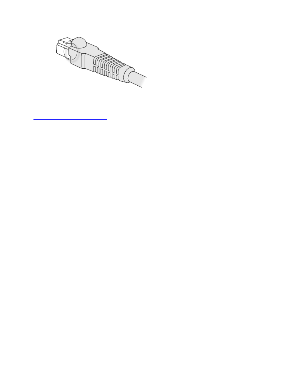
Figure 1: CAT-5 connector showing uneven sheath
Related Links
Installing the WLAN AP 8120-O on page 5
Waterproofing the Ethernet UTP cable
Before connecting the outdoor Ethernet cable to the WLAN AP 8120-O you must first waterproof the
Ethernet UTP cable or risk an electrical shock.
To waterproof the Ethernet cable, complete the following procedure:
Note:
Avaya recommends using only an certified outdoor UTP cable such as a CAT-5E cable.
Procedure
1.
Unscrew the waterproof feed through cap and extract the grommet seal.
2. Slide the Ethernet UTP cable through the compression cap, the grommet seal, and the
Ethernet feed through body.
3. Strip the end of the Ethernet UTP cable to the length required for the 8P8C plug.
4. Insert the stripped end of the cable into the plug following either EIA/TIA 568A or 568B wiring
as listed in the following table. Ensure that both ends of the cable have the same pinout for
the RJ45 connectors.
5. Crimp the 8P8C connector to the cable.
6. Verify that the crimped cable has end-to-end continuity for all eight conductors and plug
shields.
7. Install the crimped plug into the external WLAN AP 8120-O Ethernet port found on the
bottom of the AP 8120-O.
8. Screw the waterproof feed through body to the external WLAN AP 8120-O Ethernet port
threads.
9. Slide the compression grommet into the body of the feed through.
10. Push the cable through the compression cap to the feed through body by hand to tighten the
seal.
June 2014 Installation Job Aid (English) for Avaya WLAN 8100 series- WLAN AP 8120-O 7

Figure 2: Waterproofing the Ethernet plug
Table 1: EIA/TIA wiring
EIA/TIA 568-A WIRING EIA/TIA 568-B WIRING
PIN 1– Green and white PIN 1– Orange and white
PIN 2– Solid green PIN 2– Solid orange
PIN 3– Orange and white PIN 3– Green and white
PIN 4– Solid blue PIN 4– Solid blue
PIN 5– Blue and white PIN 5— Blue and white
PIN 6– Solid orange PIN 6– Solid green
PIN 7– Brown and white PIN 7– Brown and white
PIN 8– Solid brown PIN 8– Solid brown
Related Links
Installing the WLAN AP 8120-O on page
June 2014 Installation Job Aid (English) for Avaya WLAN 8100 series- WLAN AP 8120-O 8
5

Grounding the WLAN AP 8120-O
Before operating the WLAN AP 8120-O you must connect the unit to a proper ground. Complete the
following procedure to ground the WLAN AP 8120-O. Read and observe all safety warnings.
Procedure
1. Locate the enclosure cover bolt next to a ground signal.
2. Using an adjustable wrench, loosen the bolt.
3. Using the provided green ground wire, insert the spade lug underneath the bolt.
Figure 3: Grounding the WLAN AP 8120-O
4.
Use an adjustable wrench to tighten the bolt, ensuring that the spade lug is securely in place
between the bolt and the washer.
5. Connect the other end of the green ground wire to an acceptable low-impedance Earth
ground using the shortest and most direct run.
June 2014 Installation Job Aid (English) for Avaya WLAN 8100 series- WLAN AP 8120-O 9
 Loading...