

Page 1

MJH; Reviewed:
SPOC 8/4/2011
Solution & Interoperability Test Lab Application Notes
©2011 Avaya Inc. All Rights Reserved.
1 of 47
Sagemcom_SM61
These Application Notes describe the procedures for configuring Sagemcom XMediusFAX
Service Provider (SP) Edition with Avaya Aura® Session Manager and Avaya Aura®
Communication Manager.
XMediusFAX is a software based fax server that sends and receives fax calls over an IP
network. In the configuration tested, XMediusFAX interoperates with Avaya Aura® Session
Manager and Avaya Aura® Communication Manager to send/receive faxes using SIP trunks
and the T.38 fax protocol between XMediusFAX and the Avaya SIP infrastructure.
Information in these Application Notes has been obtained through DevConnect compliance
testing and additional technical discussions. Testing was conducted via the DevConnect
Program at the Avaya Solution and Interoperability Test Lab.
Avaya Solution & Interoperability Test Lab
Application Notes for Configuring Sagemcom XMediusFAX
Service Provider Edition with Avaya Aura® Session
Manager and Avaya Aura® Communication Manager
- Issue 1.0
Abstract
Page 2

MJH; Reviewed:
SPOC 8/4/2011
Solution & Interoperability Test Lab Application Notes
©2011 Avaya Inc. All Rights Reserved.
2 of 47
Sagemcom_SM61
1. Introduction
These Application Notes describe the procedures for configuring Sagemcom XMediusFAX
Service Provider (SP) Edition with Avaya Aura® Session Manager and Avaya Aura®
Communication Manager using SIP trunks.
XMediusFAX is a software based fax server that sends and receives fax calls over an IP network.
In the configuration tested, XMediusFAX interoperates with the Session Manager and
Communication Manager to send/receive faxes using SIP trunks and the T.38 protocol between
XMediusFAX and the Avaya SIP infrastructure. The compliance testing focused on fax calls to
and from the XMediusFAX fax server using various page lengths, resolutions, and fax data
speeds.
2. General Test Approach and Test Results
This section describes the general test approach used to verify the interoperability of Sagemcom
XMediusFAX SP Edition with the Avaya SIP infrastructure (Session Manager and
Communication Manager). This section also covers the test results.
2.1. Interoperability Compliance Testing
The general test approach was to make intra-site and inter-site fax calls to and from the
XMediusFAX fax server. The compliance tested configuration contained two sites. Site 2 served
as the main enterprise site and Site 1 served as a simulated PSTN or a remote enterprise site.
Inter-site calls and simulated PSTN calls were made using SIP trunks and ISDN-PRI trunks
between the sites. By using two Communication Managers and two port networks at Site 1, fax
calls across multiple TDM/IP hops were able to be tested. Faxes were sent with various page
lengths, resolutions, and at various fax data speeds. For capacity testing, 100 2-page faxes were
continuously sent between the two XMediusFAX fax servers. Serviceability testing included
verifying proper operation/recovery from network outages, unavailable resources, and
Communication Manager and XMediusFAX restarts. Fax calls were also tested with different
Avaya Media Gateway media resources to process the fax data. This included the TN2302
MedPro circuit pack, the TN2602 MedPro circuit pack in the Avaya G650 Media Gateway; and
the integrated VoIP engine of the Avaya G450 Media Gateway.
2.2. Test Results
XMediusFAX successfully passed compliance testing.
2.3. Support
For technical support on XMediusFAX, contact Sagemcom at:
Web: http://xmediusfax.sagemcom.com/support/
Phone: (888) 766-1668
Email: xmediusfax.support.americas@sagemcom.com
Page 3
MJH; Reviewed:
SPOC 8/4/2011
Solution & Interoperability Test Lab Application Notes
©2011 Avaya Inc. All Rights Reserved.
3 of 47
Sagemcom_SM61
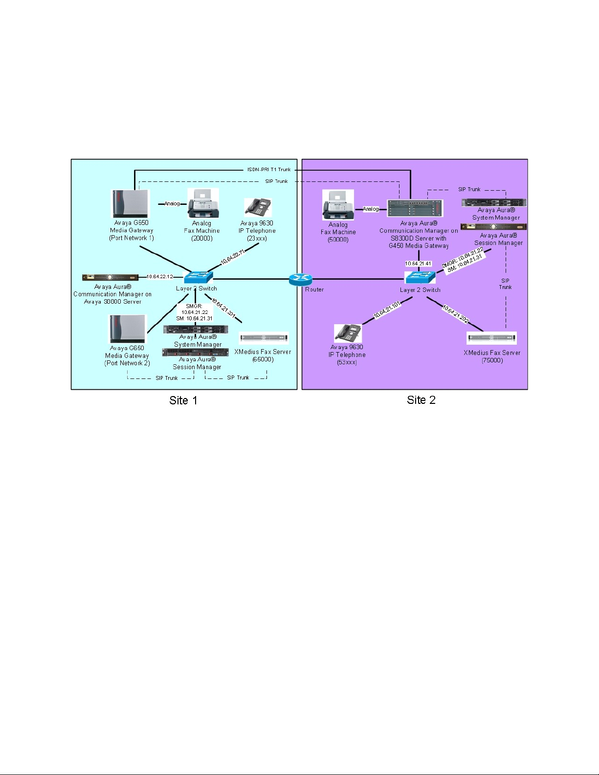
3. Reference Configuration
Figure 1 illustrates the reference configuration used during testing. In the reference
configuration, the two sites are connected via a direct SIP trunk and an ISDN-PRI trunk. Faxes
were sent between the two sites using either of these two trunks, as dictated by each individual
test case.
Figure 1: XMediusFAX with Session Manager and Communication Manager
At Site 1 consists of the following equipment:
An Avaya S8800 Server running Avaya Aura® Communication Manager with two
Avaya G650 Media Gateways. Each media gateway is configured as a separate port
network in separate IP network regions. The media resources required are provided by
the IP Media Processor (MedPro) circuit packs. Two versions of the IP MedPro circuit
pack were tested in the configuration: the TN2302AP and the TN2602AP.
An Avaya S8800 Server running Avaya Aura® System Manager. System Manager
provides management functions for Session Manager.
An Avaya S8800 Server running Avaya Aura® Session Manager.
XMediusFAX running on a Windows 2008 R2 Enterprise Server (SP1).
An analog fax machine.
Various Avaya IP endpoints (not all shown).
At Site 2 consists of the following equipment:
An Avaya S8300D Server running Avaya Aura® Communication Manager in an Avaya
G450 Media Gateway. The signaling and media resources needed to support SIP trunks
are integrated directly on the media gateway processor.
Page 4

MJH; Reviewed:
SPOC 8/4/2011
Solution & Interoperability Test Lab Application Notes
©2011 Avaya Inc. All Rights Reserved.
4 of 47
Sagemcom_SM61
A Dell™ PowerEdge™ R610 Server running Avaya Aura® System Manager. System
Manager provides management functions for Session Manager.
An HP ProLiant DL360 G7 Server running Avaya Aura® Session Manager.
XMediusFAX running on a Windows 2008 R2 Enterprise Server (SP1).
An analog fax machine
Various Avaya IP endpoints (not all shown).
Although the IP endpoints (H.323 and SIP telephones) are not involved in the faxing operations,
they are present at both sites to verify that VoIP telephone calls are not affected by the FoIP
faxing operations and vice versa.
Outbound fax calls originating from the XMediusFAX fax server are sent to Session Manager
first, and then from Session Manager to Communication Manager via SIP trunks. Based on the
dialed digits, Communication Manager will either direct the calls to the local fax machine, or to
the other site via an ISDN-PRI or SIP trunk. Inbound fax calls terminating to the XMediusFAX
fax server are sent from the local fax machine or from the remote site are received by
Communication Manager. The calls are then directed to Session Manager for onward routing to
the XMediusFAX fax server via SIP trunks.
Page 5

MJH; Reviewed:
SPOC 8/4/2011
Solution & Interoperability Test Lab Application Notes
©2011 Avaya Inc. All Rights Reserved.
5 of 47
Sagemcom_SM61
4. Equipment and Software Validated
Equipment
Software
Site 1
Avaya S8800 Server with a Avaya G650
Media Gateways:
- 2 CLANs – TN799DP
- 2 IP MedPros – TN2302AP
- 2 IP MedPros – TN2602AP
Avaya Aura® Communication Manager 6.0.1,
R016x.00.1.510.1, Patch 19009 :
- HW01, FW038
- HW20, FW120
- HW02, FW57
Avaya S8800 Server
Avaya Aura® System Manager: 6.0.0 (Build No. –
6.0.0.0.688-3.0.7.2)
(Avaya Aura® System Platform: 6.0.2.1.5)
Avaya S8800 Server
Avaya Aura® Session Manager 6.0.2.0.602004
XMediusFAX fax server (Windows 2008
R2 Enterprise Server, SP1)
6.5.5 with patch XMFSP_6.5.5.213
Fax Machine
-
Various Avaya SIP and H.323 endpoints
-
Site 2
Avaya S8300D Server with a Avaya G450
Media Gateway
Avaya Aura® Communication Manager 6.0.1,
R016x.00.1.510.1, Patch 19009
(Avaya Aura® System Platform: 6.0.3.0.3)
Dell™ PowerEdge™ R610 Server
Avaya Aura® System Manager: 6.1.0 (Build No. –
6.1.0.0.7345-6.1.5.106), Software Update Revision
No : 6.1.6.1.1087
(Avaya Aura® System Platform: 6.0.3.0.3)
HP ProLiant DL360 G7 Server
Avaya Aura® Session Manager 6.1.2.0.612004
XMediusFAX fax server (Windows 2008
R2 Enterprise Server, SP1)
6.5.5 with patch XMFSP_6.5.5.213
Fax Machine
-
Various Avaya SIP and H.323 endpoints
-
The following equipment and software were used for the reference configuration:
Page 6

MJH; Reviewed:
SPOC 8/4/2011
Solution & Interoperability Test Lab Application Notes
©2011 Avaya Inc. All Rights Reserved.
6 of 47
Sagemcom_SM61
5. Configure Communication Manager
Step
Description
1.
License
Use the display system-parameters customer-options command to verify that the
Communication Manager license has proper permissions for features illustrated in
these Application Notes. Navigate to Page 2, and verify that there is sufficient
remaining capacity for SIP trunks by comparing the Maximum Administered SIP
Trunks field value with the corresponding value in the USED column.
The license file installed on the system controls the maximum permitted. If there is
insufficient capacity, contact an authorized Avaya sales representative to make the
appropriate changes.
display system-parameters customer-options Page 2 of 11
OPTIONAL FEATURES
IP PORT CAPACITIES USED
Maximum Administered H.323 Trunks: 12000 32
Maximum Concurrently Registered IP Stations: 18000 15
Maximum Administered Remote Office Trunks: 12000 0
Maximum Concurrently Registered Remote Office Stations: 18000 0
Maximum Concurrently Registered IP eCons: 414 0
Max Concur Registered Unauthenticated H.323 Stations: 100 0
Maximum Video Capable Stations: 18000 0
Maximum Video Capable IP Softphones: 18000 1
Maximum Administered SIP Trunks: 24000 170
Maximum Administered Ad-hoc Video Conferencing Ports: 24000 0
Maximum Number of DS1 Boards with Echo Cancellation: 522 0
Maximum TN2501 VAL Boards: 128 0
Maximum Media Gateway VAL Sources: 250 1
Maximum TN2602 Boards with 80 VoIP Channels: 128 0
Maximum TN2602 Boards with 320 VoIP Channels: 128 0
Maximum Number of Expanded Meet-me Conference Ports: 300 0
(NOTE: You must logoff & login to effect the permission changes.)
This section describes the Communication Manager configuration at Site 2 to support the
network shown in Figure 1. Although not shown is this document, a similar Communication
Manager configuration would be required at Site 1.
The configuration of Communication Manager was performed using the System Access
Terminal (SAT). After the completion of the configuration, perform a save translation
command to make the changes permanent.
Page 7

MJH; Reviewed:
SPOC 8/4/2011
Solution & Interoperability Test Lab Application Notes
©2011 Avaya Inc. All Rights Reserved.
7 of 47
Sagemcom_SM61
Step
Description
2.
IP network region
Use the display ip-network-region command to view the network region settings.
The values shown below are the values used during compliance testing.
Authoritative Domain: avaya.com This field was configured to match the
domain name configured on Session Manager. The domain will appear in the
“From” header of SIP messages originating from this IP region.
Name: Any descriptive name may be used (if desired).
Intra-region IP-IP Direct Audio: yes
Inter-region IP-IP Direct Audio: yes
By default, IP-IP direct audio (media shuffling) is enabled to allow audio traffic to
be sent directly between IP endpoints without using media resources in the Avaya
Media Gateway. Shuffling can be further restricted at the trunk level on the
Signaling Group form.
Codec Set: 1 The codec set contains the list of codecs available for calls within
this IP network region.
Display ip-network-region 1 Page 1 of 20
IP NETWORK REGION
Region: 1
Location: Authoritative Domain: avaya.com
Name: FAX testing
MEDIA PARAMETERS Intra-region IP-IP Direct Audio: yes
Codec Set: 1 Inter-region IP-IP Direct Audio: yes
UDP Port Min: 2048 IP Audio Hairpinning? n
UDP Port Max: 3329
DIFFSERV/TOS PARAMETERS
Call Control PHB Value: 46
Audio PHB Value: 46
Video PHB Value: 26
802.1P/Q PARAMETERS
Call Control 802.1p Priority: 6
Audio 802.1p Priority: 6
Video 802.1p Priority: 5 AUDIO RESOURCE RESERVATION PARAMETERS
H.323 IP ENDPOINTS RSVP Enabled? n
H.323 Link Bounce Recovery? y
Idle Traffic Interval (sec): 20
Keep-Alive Interval (sec): 5
Keep-Alive Count: 5
Page 8

MJH; Reviewed:
SPOC 8/4/2011
Solution & Interoperability Test Lab Application Notes
©2011 Avaya Inc. All Rights Reserved.
8 of 47
Sagemcom_SM61
Step
Description
3.
Codecs
IP codec set 1 was used during compliance testing. Multiple codecs can be listed in
priority order to allow the codec used by a specific call to be negotiated during call
establishment. The example below shows the values used during compliance testing.
display ip-codec-set 1 Page 1 of 2
IP Codec Set
Codec Set: 1
Audio Silence Frames Packet
Codec Suppression Per Pkt Size(ms)
1: G.711MU n 2 20
2:
On Page 2, set the FAX Mode field to t.38-standard. The Modem Mode field should
be set to off.
Leave the FAX Redundancy setting at its default value of 0. A packet redundancy
level can be assigned to improve packet delivery and robustness of FAX transport over
the network (with increased bandwidth as trade-off). Avaya uses IETF RFC-2198 and
ITU-T T.38 specifications as redundancy standard. With this standard, each Fax over
IP packet is sent with additional (redundant) 0 to 3 previous fax packets based on the
redundancy setting. A setting of 0 (no redundancy) is suited for networks where packet
loss is not a problem.
display ip-codec-set 1 Page 2 of 2
IP Codec Set
Allow Direct-IP Multimedia? y
Maximum Call Rate for Direct-IP Multimedia: 2048:Kbits
Maximum Call Rate for Priority Direct-IP Multimedia: 2048:Kbits
Mode Redundancy
FAX t.38-standard 0
Modem off 0
TDD/TTY US 3
Clear-channel n 0
Page 9

MJH; Reviewed:
SPOC 8/4/2011
Solution & Interoperability Test Lab Application Notes
©2011 Avaya Inc. All Rights Reserved.
9 of 47
Sagemcom_SM61
Step
Description
4.
Node Names
Use the change node-names ip command to create a node name for the IP address of
Session Manager. Enter a descriptive name in the Name column and the IP address
assigned to Session Manager in the IP address column.
change node-names ip Page 1 of 2
IP NODE NAMES
Name IP Address
AES_21_46 10.64.21.46
CM_20_40 10.64.20.40
CM_22_12_CLAN1A 10.64.22.16
CM_22_12_CLAN2A 10.64.22.19
IPO_21_64 10.64.21.64
SM_20_31 10.64.20.31
SM_21_31 10.64.21.31
default 0.0.0.0
msgserver 10.64.21.41
procr 10.64.21.41
procr6 ::
Page 10

MJH; Reviewed:
SPOC 8/4/2011
Solution & Interoperability Test Lab Application Notes
©2011 Avaya Inc. All Rights Reserved.
10 of 47
Sagemcom_SM61
Step
Description
5.
Signaling Group
Signaling group 1 was used for the signaling group associated with the SIP trunk group
between Communication Manager and Session Manager. The signaling groups and
trunk groups between the two sites of the reference configuration is assumed to already
be in place and not described in this document. Signaling group 1 was configured
using the parameters highlighted below.
Near-end Node Name: procr This node name maps to the IP address of the Avaya
S8300D Server. Node names are defined using the change node-names ip
command.
Far-end Node Name: SM_21_31 This node name maps to the IP address of
Session Manager.
Far-end Network Region: 1 This defines the IP network region which contains
Session Manager.
Far-end Domain: avaya.com This domain is sent in the “To” header of SIP
messages of calls using this signaling group.
Direct IP-IP Audio Connections: y This field must be set to y to enable media
shuffling on the SIP trunk.
display signaling-group 1
SIGNALING GROUP
Group Number: 1 Group Type: sip
IMS Enabled? n Transport Method: tls
Q-SIP? n SIP Enabled LSP? n
IP Video? y Priority Video? n Enforce SIPS URI for SRTP? y
Peer Detection Enabled? y Peer Server: SM
Near-end Node Name: procr Far-end Node Name: SM_21_31
Near-end Listen Port: 5061 Far-end Listen Port: 5061
Far-end Network Region: 1
Far-end Domain: avaya.com
Bypass If IP Threshold Exceeded? n
Incoming Dialog Loopbacks: eliminate RFC 3389 Comfort Noise? n
DTMF over IP: rtp-payload Direct IP-IP Audio Connections? y
Session Establishment Timer(min): 3 IP Audio Hairpinning? n
Enable Layer 3 Test? y Initial IP- IP Direct Media? n
H.323 Station Outgoing Direct Media? n Alternate Route Timer(sec): 6
Page 11

MJH; Reviewed:
SPOC 8/4/2011
Solution & Interoperability Test Lab Application Notes
©2011 Avaya Inc. All Rights Reserved.
11 of 47
Sagemcom_SM61
Step
Description
6.
Trunk Group
Trunk group 1 was used for the SIP trunk group between Communication Manager and
Session Manager. The signaling groups and trunk groups between the two sites of the
reference configuration is assumed to already be in place and not described in this
document. Trunk group 1 was configured using the parameters highlighted below.
Group Type: sip This field sets the type of the trunk group.
TAC: 101 Enter an valid value consistent with the Communication Manager dial
plan
Member Assignment Method: auto Set to Auto.
Signaling Group: 1 This field is set to the signaling group shown in the previous
step.
Number of Members: 50 This field represents the number of trunk group
members in the SIP trunk group. It determines how many simultaneous SIP calls
can be supported by the configuration. Each SIP call between two SIP endpoints
(whether internal or external) requires two SIP trunks for the duration of the call.
Thus, a call from a SIP telephone to another SIP telephone will use two SIP trunks.
A call between a non-SIP telephone and a SIP telephone will only use one trunk.
display trunk-group 1 Page 1 of 21
TRUNK GROUP
Group Number: 1 Group Type: sip CDR Reports: y
Group Name: to SM_21_31 COR: 1 TN: 1 TAC: 101
Direction: two-way Outgoing Display? n
Dial Access? n Night Service:
Queue Length: 0
Service Type: tie Auth Code? n
Member Assignment Method: auto
Signaling Group: 1
Number of Members: 50
Page 12

MJH; Reviewed:
SPOC 8/4/2011
Solution & Interoperability Test Lab Application Notes
©2011 Avaya Inc. All Rights Reserved.
12 of 47
Sagemcom_SM61
Step
Description
Trunk Group – continued
On Page 3:
The Numbering Format field was set to unk-pvt. This field specifies the format
of the calling party number sent to the far-end.
The default values may be retained for the other fields.
display trunk-group 1 Page 3 of 21
TRUNK FEATURES
ACA Assignment? n Measured: none
Maintenance Tests? y
Numbering Format: unk-pvt
UUI Treatment: service-provider
Replace Restricted Numbers? n
Replace Unavailable Numbers? n
Modify Tandem Calling Number: no
Show ANSWERED BY on Display? y
7.
Private Numbering
Private Numbering defines the calling party number to be sent to the far-end. In the
example shown below, all calls originating from a 5-digit extension beginning with 5
and routed across any trunk group will be sent as a 5 digit calling number. The calling
party number is sent to the far-end in the SIP “From” header.
display private-numbering 0 Page 1 of 2
NUMBERING - PRIVATE FORMAT
Ext Ext Trk Private Total
Len Code Grp(s) Prefix Len
5 5 5 Total Administered: 1
Maximum Entries: 540
Page 13
MJH; Reviewed:
SPOC 8/4/2011
Solution & Interoperability Test Lab Application Notes
©2011 Avaya Inc. All Rights Reserved.
13 of 47
Sagemcom_SM61
Step
Description
8.
Automatic Alternate Routing
Automatic Alternate Routing (AAR) was used to route calls either to Session Manager
or to the Communication Manager at the other site. Use the change aar analysis
command to create an entry in the AAR Digit Analysis Table. The example below
shows numbers that begin with 75 and are 5 digits long use route pattern 1 (to Session
Manager). Numbers that begin with 20000 or 65 and are 5 digits long use route pattern
7, which routes calls to Communication Manager at the other site via a SIP trunk (route
pattern 8 was also used at times to route calls to Communication Manager at the other
site via an ISDN-PRI trunk).
display aar analysis 2 Page 1 of 2
AAR DIGIT ANALYSIS TABLE
Location: all Percent Full: 1
Dialed Total Route Call Node ANI
String Min Max Pattern Type Num Reqd
2 3 3 5 aar n
20000 5 5 7 aar n
23 5 5 8 aar n
531 5 5 1 unku n
532 5 5 1 unku n
59997 5 5 99 aar n
65 5 5 7 aar n
75 5 5 1 aar n
Page 14

MJH; Reviewed:
SPOC 8/4/2011
Solution & Interoperability Test Lab Application Notes
©2011 Avaya Inc. All Rights Reserved.
14 of 47
Sagemcom_SM61
Step
Description
9.
Route Pattern
Route pattern 1 was used for calls destined for the XMediusFAX fax server through
Session Manager. Route patterns 7 and 8 (not shown) were used for calls destined for
the other site in the reference configuration. Route pattern 1 was configured using the
parameters highlighted below.
Pattern Name: Any descriptive name.
Grp No: 1 This field is set to the trunk group number defined in Step 5.
FRL: 0 This field sets the Facility Restriction Level of the trunk. It must be set to
an appropriate level to allow authorized users to access the trunk. The level of 0 is
the least restrictive.
change route-pattern 1 Page 1 of 3
Pattern Number: 1 Pattern Name: to SM_21_31
SCCAN? n Secure SIP? n
Grp FRL NPA Pfx Hop Toll No. Inserted DCS/ IXC
No Mrk Lmt List Del Digits QSIG
Dgts Intw
1: 1 0 0 n user
2: n user
3: n user
4: n user
5: n user
6: n user
BCC VALUE TSC CA-TSC ITC BCIE Service/Feature PARM No. Numbering LAR
0 1 2 M 4 W Request Dgts Format
Subaddress
1: y y y y y n n rest lev0-pvt none
2: y y y y y n n rest none
3: y y y y y n n rest none
4: y y y y y n n rest none
5: y y y y y n n rest none
6: y y y y y n n rest none
Page 15

MJH; Reviewed:
SPOC 8/4/2011
Solution & Interoperability Test Lab Application Notes
©2011 Avaya Inc. All Rights Reserved.
15 of 47
Sagemcom_SM61
6. Configure Session Manager
This section provides the procedures for configuring Session Manager (version 6.1) as
provisioned at Site 2 in the reference configuration. Although not shown is this document, a
similar Session Manager configuration would be required at Site 1 (using the appropriate version
6.0 screens). All provisioning for Session Manager is performed via the System Manager web
interface.
The following sections assume that Session Manager and System Manager have been installed
and that network connectivity exists between the two platforms.
The Session Manager server provides the network interface for all inbound and outbound SIP
signaling and media transport to all provisioned SIP entities. During compliance testing, the IP
address assigned to the Security Module interface is 10.64.21.31 as specified in Figure 1. The
Session Manager server also has a separate network interface used for connectivity to System
Manager for provisioning Session Manager. The IP address assigned to the Session Manager
management interface is 10.64.21.30.
The procedures described in this section include configurations in the following areas:
SIP Domains – SIP Domains are the domains for which Session Manager is authoritative in
routing SIP calls. In other words, for calls to such domains, Session Manager applies
Network Routing Policies to route those calls to SIP Entities. For calls to other domains,
Session Manager routes those calls to another SIP proxy (either a pre-defined default SIP
proxy or one discovered through DNS).
Locations – Locations define the physical and/or logical locations in which SIP Entities
reside. Call Admission Control (CAC) / bandwidth management may be administered for
each location to limit the number of calls to and from a particular Location.
Adaptations – Adaptations are used to apply any necessary protocol adaptations, e.g.,
modify SIP headers, and apply any necessary digit conversions for the purpose of interworking with specific SIP Entities.
SIP Entities – SIP Entities represent SIP network elements such as Session Manager
instances, Communication Manager systems, Session Border Controllers, SIP gateways, SIP
trunks, and other SIP network devices.
Entity Links – Entity Links define the SIP trunk/link parameters, e.g., ports, protocol
(UDP/TCP/TLS), and trust relationship, between Session Manager instances and other SIP
Entities.
Time Ranges – Time Ranges specify customizable time periods, e.g., Monday through
Friday from 9AM to 5:59PM, Monday through Friday 6PM to 8:59AM, all day Saturday and
Sunday, etc. A Network Routing Policy may be associated with one or more Time Ranges
during which the Network Routing Policy is in effect.
Routing Policies – Routing Policies are used in conjunction with a Dial Patterns to
specify a SIP Entity that a call should be routed to.
Dial Patterns – A Dial Pattern specifies a set of criteria and a set of Network Routing
Policies for routing calls that match the criteria. The criteria include the called party number
and SIP domain in the Request-URI, and the Location from which the call originated. For
Page 16

MJH; Reviewed:
SPOC 8/4/2011
Solution & Interoperability Test Lab Application Notes
©2011 Avaya Inc. All Rights Reserved.
16 of 47
Sagemcom_SM61
example, if a call arrives at Session Manager and matches a certain Dial Pattern, then Session
1.
Login
Access the System Manager administration web interface by entering
https://<ip-addr>/SMGR/ as the URL in an Internet browser, where <ip-addr> is the
IP address of the System Manager server.
Log in with the appropriate credentials. The main page for the administrative interface
is shown below.
Manager selects one of the Network Routing Policies specified in the Dial Pattern. The
selected Network Routing Policy in turn specifies the SIP Entity to which the call is to be
routed.
Page 17

MJH; Reviewed:
SPOC 8/4/2011
Solution & Interoperability Test Lab Application Notes
©2011 Avaya Inc. All Rights Reserved.
17 of 47
Sagemcom_SM61
2.
Add SIP Domain
The Routing menu contains all the configuration tasks listed at the beginning of this
section.
During compliance testing, one SIP Domain was configured.
Navigate to RoutingDomains, and click the New button (not shown) to add the SIP
domain with
Name: avaya.com (as set in Section 5, Step 2)
Notes: optional descriptive text
Click Commit to save the configuration.
Page 18

MJH; Reviewed:
SPOC 8/4/2011
Solution & Interoperability Test Lab Application Notes
©2011 Avaya Inc. All Rights Reserved.
18 of 47
Sagemcom_SM61
3.
Add Location
Locations identify logical and/or physical locations where SIP entities reside. Only one
Location was configured at each site for compliance testing.
Navigate to RoutingLocations and click the New button (not shown) to add the
Location.
Under General:
Name: a descriptive name
Notes: optional descriptive text
Under Location Pattern, click the Add button to add a new line:
IP Address Pattern: 10.64.21.*
Notes: optional descriptive text
Click Commit to save the configuration.
Page 19

MJH; Reviewed:
SPOC 8/4/2011
Solution & Interoperability Test Lab Application Notes
©2011 Avaya Inc. All Rights Reserved.
19 of 47
Sagemcom_SM61
4.
Add Adaptation
An Adaptation was created and applied to the “Fax Server” SIP entity to override the
destination domain as shown below.
The ingressOverrideDestinationDomain (iodstd) Module paramater replaces the
domain in the Request-URI, To Header (if administered), and Notify/messagesummary body with the given value (e.g. avaya.com) for ingress only.
The override DestinationDomain (odstd) Module paramater replaces the domain in
the Request-URI, To Header (if administered), Refer-To header, and Notify/messagesummary body with the given value (e.g. the IP address of the fax server 10.64.21.202)
for egress only.
Page 20

MJH; Reviewed:
SPOC 8/4/2011
Solution & Interoperability Test Lab Application Notes
©2011 Avaya Inc. All Rights Reserved.
20 of 47
Sagemcom_SM61
5.
Add SIP Entities
A SIP Entity must be added for Session Manager and for each SIP-based telephony
system supported by it using SIP trunks. During compliance testing, a SIP Entity was
added for the Session Manager itself, Communication Manager, and the XMediusFAX
fax server.
Navigate to RoutingSIP Entities, and click the New button (not shown) to add a
SIP Entity. The configuration details for the SIP Entity defined for Session Manager
are as follows:
Under General:
Name: a descriptive name
FQDN or IP Address: 10.64.21.31 as specified in Figure 1. This is the IP
address assigned to the SM-100 security module installed in the Session
Manager.
Type: select Session Manager
Under Port, click Add, then edit the fields in the resulting new row as shown below:
Port: 5061. This is the port number on which the system listens for SIP
requests.
Protocol: TLS. The TLS transport protocol was used between Session Manager
and Communication Manager.
Default Domain: select the SIP Domain created in Step 2.
Repeat the three bullets above, but select 5060 for Port and UDP for Protocol.
The UPD protocol was used between Session Manager and the XMediusFAX
fax server.
Default settings can be used for the remaining fields. Click Commit to save the SIP
Entity definition.
Page 21

MJH; Reviewed:
SPOC 8/4/2011
Solution & Interoperability Test Lab Application Notes
©2011 Avaya Inc. All Rights Reserved.
21 of 47
Sagemcom_SM61
Add SIP Entities (continued) – Session Manager
The screens below show the SIP Entity configuration details for the Session Manager.
Page 22

MJH; Reviewed:
SPOC 8/4/2011
Solution & Interoperability Test Lab Application Notes
©2011 Avaya Inc. All Rights Reserved.
22 of 47
Sagemcom_SM61
Add SIP Entities (continued) – Communication Manager
The screen below shows the SIP Entity configuration details for the Communication
Manager. Note the CM selection for Type.
Page 23

MJH; Reviewed:
SPOC 8/4/2011
Solution & Interoperability Test Lab Application Notes
©2011 Avaya Inc. All Rights Reserved.
23 of 47
Sagemcom_SM61
Add SIP Entities (continued) – XMediusFax
The screen below shows the SIP Entity configuration details for the XMediusFAX fax
server. Note the Other selection for Type, and the Adaptation created Step 4 of this
section is selected.
Page 24

MJH; Reviewed:
SPOC 8/4/2011
Solution & Interoperability Test Lab Application Notes
©2011 Avaya Inc. All Rights Reserved.
24 of 47
Sagemcom_SM61
6.
Add Entity Links
A SIP trunk between Session Manager and a telephony system is described by an
Entity link. Two Entity Links were created: one between Session Manager and
Communication Manger; the other between Session Manager and the XMediusFAX
fax server.
Navigate to RoutingEntity Links, and click the New button (not shown) to add a
new Entity Link. The screen below shows the configuration details for the Entity Link
connecting Session Manager to Communication Manager.
Name: a descriptive name
SIP Entity 1: select the Session Manager SIP Entity.
Port: 5061. This is the port number to which the other system sends SIP
requests.
SIP Entity 2: select the Communication Manager SIP Entity.
Port: 5061. This is the port number on which the other system receives SIP
requests.
Trusted: check this box
Protocol: select TLS as the transport protocol.
Notes: optional descriptive text
Click Commit to save the configuration.
Page 25

MJH; Reviewed:
SPOC 8/4/2011
Solution & Interoperability Test Lab Application Notes
©2011 Avaya Inc. All Rights Reserved.
25 of 47
Sagemcom_SM61
Add Entity Links (continued)
The Entity Link for connecting Session Manager to the XMediusFAX fax server was
similarly defined as shown in the screen below.
Page 26

MJH; Reviewed:
SPOC 8/4/2011
Solution & Interoperability Test Lab Application Notes
©2011 Avaya Inc. All Rights Reserved.
26 of 47
Sagemcom_SM61
7.
Add Time Ranges
Before adding routing policies (configured in next step), time ranges must be defined
during which the policies will be active. One Time Range was defined that would
allow routing to occur at anytime.
Navigate to RoutingTime Ranges, and click the New button to add a new Time
Range:
Name: a descriptive name
Mo through Su: check the box under each of these headings
Start Time: enter 00:00
End Time: enter 23:59
Click Commit to save this time range. The screen below shows the configured Time
Range.
Page 27

MJH; Reviewed:
SPOC 8/4/2011
Solution & Interoperability Test Lab Application Notes
©2011 Avaya Inc. All Rights Reserved.
27 of 47
Sagemcom_SM61
8.
Add Routing Policies
Routing policies describe the conditions under which calls will be routed to the SIP
Entities connected to the Session Manager. Two routing policies were added – one for
routing calls to Communication Manager, and the other for routing calls to the
XMediusFAX fax server.
Navigate to RoutingRouting Policies, and click the New button (not shown) to add
a new Routing Policy.
Under General:
Name: a descriptive name
Notes: optional descriptive text
Under SIP Entity as Destination
Click Select to select the appropriate SIP Entity to which the routing policy applies
(not shown).
Under Time of Day
Click Add to select the Time Range configured in the previous step (not shown).
Default settings can be used for the remaining fields. Click Commit to save the
configuration.
Page 28

MJH; Reviewed:
SPOC 8/4/2011
Solution & Interoperability Test Lab Application Notes
©2011 Avaya Inc. All Rights Reserved.
28 of 47
Sagemcom_SM61
Add Routing Policies (continued)
The screens below show the configuration details for the two Routing Policies used
during compliance testing.
Page 29

MJH; Reviewed:
SPOC 8/4/2011
Solution & Interoperability Test Lab Application Notes
©2011 Avaya Inc. All Rights Reserved.
29 of 47
Sagemcom_SM61
9.
Add Dial Patterns
Dial Patterns define digit strings to be matched against dialed numbers for directing
calls to the appropriate SIP Entities. 5-digit extensions beginning with “5” resided on
Communication Manager at Site 2. 5-digit extensions matching “20000” or “65000”
were routed to the local Communication Manager for onward routing to Site 1. 5-digit
extensions beginning with “75” were routed to the XMediusFAX fax server. Therefore
4 Dial Patterns were created accordingly.
Navigate to RoutingDial Patterns, click the New button (not shown) to add a new
Dial Pattern.
Under General:
Pattern: dialed number or prefix
Min: minimum length of dialed number
Max: maximum length of dialed number
SIP Domain: select the SIP Domain created in Step 2 (or select –ALL– to be
less restrictive)
Notes: optional descriptive text
Under Originating Locations and Routing Policies
Click Add to select the appropriate originating Location and Routing Policy from the
list (not shown).
Under Time of Day
Click Add to select the time range configured in Step 7.
Default settings can be used for the remaining fields. Click Commit to save the
configuration.
Page 30

MJH; Reviewed:
SPOC 8/4/2011
Solution & Interoperability Test Lab Application Notes
©2011 Avaya Inc. All Rights Reserved.
30 of 47
Sagemcom_SM61
Add Dial Patterns (continued)
The screens below shows the configuration details for the Dialed Patterns defined for
routing calls to Communication Manager at the main enterprise site.
Page 31

MJH; Reviewed:
SPOC 8/4/2011
Solution & Interoperability Test Lab Application Notes
©2011 Avaya Inc. All Rights Reserved.
31 of 47
Sagemcom_SM61
Page 32

MJH; Reviewed:
SPOC 8/4/2011
Solution & Interoperability Test Lab Application Notes
©2011 Avaya Inc. All Rights Reserved.
32 of 47
Sagemcom_SM61
Page 33

MJH; Reviewed:
SPOC 8/4/2011
Solution & Interoperability Test Lab Application Notes
©2011 Avaya Inc. All Rights Reserved.
33 of 47
Sagemcom_SM61
Add Dial Patterns (continued)
The screen below shows the configuration details for the Dialed Pattern defined for
routing calls to the XMediusFAX fax server.
Page 34

MJH; Reviewed:
SPOC 8/4/2011
Solution & Interoperability Test Lab Application Notes
©2011 Avaya Inc. All Rights Reserved.
34 of 47
Sagemcom_SM61
7. Configure Sagemcom XMediusFAX
Step
Description
1.
Prepare the fax server for launching the XMediusFAX software
Consult Sagemcom for requirements and instructions.
2.
Launch the Application
On the XMediusFAX server, launch the XMediusFAX application from the Windows
Start Menu. Navigate to Start All Programs XMediusFAX XMediusFAX.
A login screen appears. Log in with proper credentials. Click the OK button.
This section describes the configuration of XMediusFAX. It assumes that the application and all
required software components have been installed and properly licensed. The number of
channels supported by the XMediusFAX server is controlled via an XMediusFAX server license
file. For instructions on sending and receiving faxes, consult the XMediusFAX Administrator
Guide [5] and User Guide [7].
The examples shown in this section refer to Site 2. Unless specified otherwise, the same steps
also apply to Site 1 using values appropriate for Site 1 from Figure 1.
Page 35

MJH; Reviewed:
SPOC 8/4/2011
Solution & Interoperability Test Lab Application Notes
©2011 Avaya Inc. All Rights Reserved.
35 of 47
Sagemcom_SM61
Step
Description
3.
Configure Driver Properties
On the main screen, navigate to XMediusFAX System Configuration Hosts
WIN-8E644SJFMQO Driver in the left hand tree menu. Right-click on Driver
and select Properties (not shown).
Page 36

MJH; Reviewed:
SPOC 8/4/2011
Solution & Interoperability Test Lab Application Notes
©2011 Avaya Inc. All Rights Reserved.
36 of 47
Sagemcom_SM61
Step
Description
4.
General Options
On the Driver Properties screen, select the Options tab. Set the Maximum Number
Of Channels and Preferred Number Of Channels fields under T.38 Channel
Configuration to the number of simultaneous faxes to be processed.
Page 37

MJH; Reviewed:
SPOC 8/4/2011
Solution & Interoperability Test Lab Application Notes
©2011 Avaya Inc. All Rights Reserved.
37 of 47
Sagemcom_SM61
Step
Description
5.
T.38 Parameters
On the Driver Properties screen, select the T.38 tab. Configure the fields as follows:
Received Document Encoding – Set this field to the highest encoding allowed.
For the compliance test, this value was set to Group 3 (1d).
Terminal Resolution Capacity – Set this field to the highest resolution
allowed desired. For the compliance test, this value was set to High (200x200).
Page 38

MJH; Reviewed:
SPOC 8/4/2011
Solution & Interoperability Test Lab Application Notes
©2011 Avaya Inc. All Rights Reserved.
38 of 47
Sagemcom_SM61
Step
Description
6.
SIP Parameters
On the Driver Properties screen, select the SIP tab. Configure the fields as follows:
Local SIP UDP port – Set this field to match the first Port field in Section 6,
Step 6. During compliance testing, UDP was used as the transport layer protocol by
the XMediusFAX fax server.
Page 39

MJH; Reviewed:
SPOC 8/4/2011
Solution & Interoperability Test Lab Application Notes
©2011 Avaya Inc. All Rights Reserved.
39 of 47
Sagemcom_SM61
Step
Description
7.
Peer List
On the Driver Properties screen, select the Peer List tab. To add a new SIP peer,
select the Add SIP Peer button and enter the values shown in Step 8. To view an
existing peer, highlight the peer in the list and click Properties. The example below
shows the peer list after the Session Manager interface, 10.64.21.31, has been added to
the list.
Page 40

MJH; Reviewed:
SPOC 8/4/2011
Solution & Interoperability Test Lab Application Notes
©2011 Avaya Inc. All Rights Reserved.
40 of 47
Sagemcom_SM61
Step
Description
8.
Peer Properties
On the Peer Properties screen, configure as follows:
Host Name – Set this field to the IP address of Session Manager.
Transport: Set this field to UDP. During compliance testing, UDP was used as
the transport layer protocol by the XMediusFAX fax server.
Port - Set this field to 5060.
Check the Send CNG using RTP field.
Page 41

MJH; Reviewed:
SPOC 8/4/2011
Solution & Interoperability Test Lab Application Notes
©2011 Avaya Inc. All Rights Reserved.
41 of 47
Sagemcom_SM61
Step
Description
9.
Codec
On the Peer Properties screen, select the Advanced tab. To add a codec for the SIP
peer, select the Add button and select the values from the drop-down menu. To view
an existing codec, highlight the codec in the list and click Properties. The example
below shows the codec list supported by the newly added SIP peer.
Page 42

MJH; Reviewed:
SPOC 8/4/2011
Solution & Interoperability Test Lab Application Notes
©2011 Avaya Inc. All Rights Reserved.
42 of 47
Sagemcom_SM61
Step
Description
10.
Dial Plan
On the Driver Properties screen, select the Dial Plan tab. To add a new entry to the
dial plan, select the Add button and enter the values shown in Step 11. To view an
existing entry, highlight the entry in the list and click Properties to get the Number
Pattern Properties screen. The example below shows the dial plan after the entry for
* (any value) has been added to the list.
Page 43

MJH; Reviewed:
SPOC 8/4/2011
Solution & Interoperability Test Lab Application Notes
©2011 Avaya Inc. All Rights Reserved.
43 of 47
Sagemcom_SM61
Step
Description
11.
Number Pattern Properties
On the Number Pattern Properties screen, configure as follows:
Number Pattern – Set this field to the pattern to match. In this example, the
value of * indicates any dialed number is acceptable.
Peer – Click the Add button. In the Peer Properties window that appears (not
shown), enter the Peer IP Address and Preference value of 1 and click OK. In this
example, only one peer is configured.
Lastly, click OK on the Driver Properties screen shown in Step 10, to accept the
Driver Configuration.
Page 44

MJH; Reviewed:
SPOC 8/4/2011
Solution & Interoperability Test Lab Application Notes
©2011 Avaya Inc. All Rights Reserved.
44 of 47
Sagemcom_SM61
Step
Description
12.
Once all the driver properties have been configured, go to Start Control Panel
Administrative Tools Services to stop and start the XMFaxDriver service to make
the changes take effect.
Page 45

MJH; Reviewed:
SPOC 8/4/2011
Solution & Interoperability Test Lab Application Notes
©2011 Avaya Inc. All Rights Reserved.
45 of 47
Sagemcom_SM61
Step
Description
13.
Configure Channels
On the main screen, navigate to XMediusFAX System Configuration Hosts
WIN-8E644SJFMQO Driver Channels in the left hand tree menu. Right-click
on each channel in the right pane to set the Mode to Send, Receive or Both. During
compliance testing, 9 channels were set to Send and 14 channels were set to Receive.
s
Page 46

MJH; Reviewed:
SPOC 8/4/2011
Solution & Interoperability Test Lab Application Notes
©2011 Avaya Inc. All Rights Reserved.
46 of 47
Sagemcom_SM61
8. Verification Steps
The following steps may be used to verify the configuration:
Using System Manager, navigate to Session ManagerSystem StatusSIP Entity
Monitoring, and click on the appropriate SIP Entities to verify that the Entity Link to
Communication Manager is up.
From the Communication Manager SAT, use the status signaling-group x command to
verify that the SIP signaling group is in-service (where x is the signaling group number
associated with the trunk between Communication Manager and Session Manager).
From the Communication Manager SAT, use the status trunk-group y command to
verify that the SIP trunk group is in-service (where y is the trunk group number for the
trunk between Communication Manager and Session Manager).
Verify that fax calls can be placed to/from the XMediusFAX fax server at each site.
From the Avaya Communication Manager SAT, use the list trace tac command to verify
that fax calls are routed over the expected trunks.
9. Conclusion
Sagemcom XMediusFAX passed compliance testing. These Application Notes describe the
procedures required to configure Sagemcom XMediusFAX to interoperate with Session Manager
and Communication Manager to support the network shown in Figure 1.
10. Additional References
Product documentation for Avaya products may be found at http://support.avaya.com.
[1] Avaya AuraTM Communication Manager Feature Description and Implementation, Doc #
555-245-205, August 2010.
[2] Administering Avaya AuraTM Communication Manager, Doc # 03-300509, August 2010.
[3] Administering Avaya Aura® Session Manager, Doc # 03-603324, May 2011.
[4] Installing and Configuring Avaya Aura® Session Manager, Doc # 03-6034723, April 2011.
Product documentation for XMediusFAX 6.5.5 may be may be obtained from Sagemcom.
[5] Sagemcom XMediusFAX Administrator Guide, September 2010
[6] Sagemcom XMediusFAX Installation and Maintenance Guide, September 2010
[7] Sagemcom XMediusFAX User Guide, September 2010
Page 47

MJH; Reviewed:
SPOC 8/4/2011
Solution & Interoperability Test Lab Application Notes
©2011 Avaya Inc. All Rights Reserved.
47 of 47
Sagemcom_SM61
©2011 Avaya Inc. All Rights Reserved.
Avaya and the Avaya Logo are trademarks of Avaya Inc. All trademarks identified by ® and
™ are registered trademarks or trademarks, respectively, of Avaya Inc. All other trademark s
are the property of their respective owners. The information provided in these Application
Notes is subject to change without notice. The configurations, technical data, and
recommendations provided in these Application Notes are believed to be accurate and
dependable, but are presented without express or implied warranty. Users are responsible for
their application of any products specified in these Application Notes.
Please e-mail any questions or comments pertaining to these Application Notes along with the
full title name and filename, located in the lower right corner, directly to the Avaya
DevConnect Program at devconnect@avaya.com.
 Loading...