

Page 1

SIP Firmware Release 2.0 for IP
Phone 1140E Administration
NN43113-300
.
Page 2

Document status: Standard
Document version: 03.09
Document date: 15 September 2008
Copyright © 2008, Nortel Networks
All Rights Reserved.
LEGAL NOTICE
While the information in this document is believed to be accurate and reliable, except as otherwise expressly agreed
to in writing NORTEL PROVIDES THIS DOCUMENT AS IS WITHOUT WARRANTY OR CONDITION OF ANY
KIND, EITHER EXPRESS OR IMPLIED. The information and/or products described in this document are subject
to change without notice.
Sourced in Canada
Nortel, the Nortel Logo, the Globemark, SL-1, Meridian 1, and Succession are trademarks of Nortel Networks.
All other trademarks are the property of their respective owners.
Page 3

Contents
New in this release 7
Server Supplied User Credentials 7
Expansion module for the IP Phone 1100 Series when connected to IP Phone 1100
IEEE 802.1ab Link Layer Discovery support 7
IP Phone 1140E with SIP firmware PRACK and UPDATE support feature 8
RFC 3581 8
RTP port configuration 9
Voice Quality Monitoring 9
Distinctive ringing and Call waiting 9
Shared Call Appearance 10
Transfer to Voice Mail 10
Other changes 10
How to Get Help 13
Getting Help from the Nortel Web site 13
Getting Help over the telephone from a Nortel Solutions Center 13
Getting Help from a specialist using an Express Routing Code 14
Getting Help through a Nortel distributor or reseller 14
3
series SIP Client 7
Revision history 10
Introduction to this guide 15
Subject 15
Intended audience 15
Acronyms 15
Related publications 17
Overview 19
Introduction 19
SIP overview 19
IP Phone 1140E with SIP Firmware 19
Related documentation 20
Installation overview 21
Supported SIP proxy servers 24
Before installation 25
Introduction 25
SIP Firmware Release 2.0 for IP Phone 1140E Administration
Copyright © 2008, Nortel Networks
.
NN43113-300 03.09 Standard
15 September 2008
Page 4

4 Contents
Preinstallation 25
Configure the provisioning server 29
How provisioning works 29
Download the SIP Firmware to the provisioning server 30
Create the SIP provisioning file on the provisioning server 30
Setting the default language on the IP Phone 1140E to French 35
Create the device configuration file on the provisioning server 36
Device configuration commands 40
Create the set configuration file on the provisioning server 59
Set configuration commands 60
Create the Dialing Plan file on the provisioning server 61
Dialing function description 63
Downloadable WAV files 67
Configure the DHCP server 69
Partial DHCP mode 69
Full DHCP mode 70
Configure the DHCP server to support Full DHCP mode 71
DHCP VLAN Auto Discovery 73
Physically install the IP Phone 1140E 75
Upgrade and convert the IP Phone 1140E firmware 79
Introduction 79
Upgrade the SIP Firmware on the IP Phone 1140E 79
Download the SIP Firmware to the provisioning server 79
Modify the SIP provisioning file 80
Upgrade to the minimum UNIStim Firmware 81
Identify the current version of UNIStim Firmware 81
Upgrade UNIStim Firmware to the minimum required UNIStim Firmware 84
Convert UNIStim Firmware to SIP Firmware on the IP Phone 1140E 87
Voice Quality Monitoring 91
Feature overview 91
VQMon set-up 91
Server set-up 92
How VQMon works 92
End of call report 93
Session interval report 93
Alert interval report 93
Device Settings on the IP Phone 1140E with SIP Firmware 95
Introduction 95
802.1x (EAP) Port-based network access control 98
Configure the device settings 111
SIP Firmware Release 2.0 for IP Phone 1140E Administration
Copyright © 2008, Nortel Networks
.
NN43113-300 03.09 Standard
15 September 2008
Page 5

Contents 5
Multiple Appearance Directory Number (Single Call
Arrangement) 123
Vertical services 123
Privacy 124
Feature dependencies and restrictions 124
Emergency 911 - Operator control of disconnect 125
Overview 125
Location information 125
Dialing plan configuration 126
Characteristics of E911 calls 126
IP Phone 1140E restrictions 127
Service package restrictions 127
Distinctive Ringing feature 127
NAT firewall traversal 129
Three-port switch and VLAN functionality 131
System overview 131
SIP messages supported by the IP Phone 1140E 135
SIP methods 135
SIP responses 136
1xx Response--Information Responses 136
2xx Response--Successful responses 137
3xx Response--Redirection responses 137
4xx Response--Request failure responses 138
5xx Response--Server failure responses 140
6xx Response--Global responses 141
Default error handling 141
SIP header fields 141
Session description protocol usage 144
SDP and Call Hold 145
Transport layer protocols 145
SIP security authentication 145
SIP DTMF Digit transport 146
Supported subscriptions 146
Supported instant messaging 146
Maintenance and troubleshooting 149
Convert SIP Firmware to UNIStim Firmware 149
IP Phone 1140E diagnostics 150
Index 153
SIP Firmware Release 2.0 for IP Phone 1140E Administration
Copyright © 2008, Nortel Networks
.
NN43113-300 03.09 Standard
15 September 2008
Page 6

6 Contents
SIP Firmware Release 2.0 for IP Phone 1140E Administration
Copyright © 2008, Nortel Networks
.
NN43113-300 03.09 Standard
15 September 2008
Page 7

New in this release
The following changes are introduced for SIP Firmware Release 2.0 for IP
Phone 1140E Administration (NN43113-300).
Server Supplied User Credentials
This release adds support for downloading a users login credentials from
a central repository. The login credentials are associated with the MAC
address of the set. This feature simplifies installation of the IP Phone by
allowing it to automatically log into the SIP proxy server without end user
intervention.
To provision this feature see "Set configuration commands" (page 60).
Expansion module for the IP Phone 1100 Series when connected to IP Phone 1100 series SIP Client
An expansion module providing 18 additional feature keys, can be attached
to a Nortel IP Phone 1140E with SIP firmware. Up to three expansion
modules can be added to the phone. The feature keys in the expansion
module provide the same functionality as the feature keys on the IP Phone.
7
Additionally, this feature adds the ability to automatically populate the extra
feature keys, using the friends list or the address book as sources.
For more information on the Expansion module refer to, SIP Firmware for IP
Phone 1100 Series Expansion Module User Guide (NN43110-301).
To provision this feature see "Feature configuration commands " (page 42).
IEEE 802.1ab Link Layer Discovery support
Discovery protocols provide a mechanism to identify devices attached to a
network. Popular network-management systems use automated discovery
to obtain the topology of a network. These applications detect adds and
removals, provide Layer 3 information, and group the attached devices
into IP subnets.
SIP Firmware Release 2.0 for IP Phone 1140E Administration
Copyright © 2008, Nortel Networks
.
NN43113-300 03.09 Standard
15 September 2008
Page 8

8 New in this release
IEEE has developed 802.1ab Link Layer Discovery Protocol (LLDP), a
standard for discovering the physical topology between neighboring devices.
802.1ab LLDP defines a standard method for Ethernet network devices
such as switches, routers and IP Phones to advertise information about
themselves to other nodes on the network and store the information they
discover in a MIB.
This feature implements 802.1ab and its IEEE 802.1/802.3 and TIA-MED
organizationally specific extensions.
To provision this feature see "802.1ab Link Layer Discovery Protocol"
(page 99) and Procedure 13 "Provisioning the Device Settings parameters"
(page 111). The parameters in Table 18 "TLV formats" (page 100) can be
configured on the IP Phone.
IP Phone 1140E with SIP firmware PRACK and UPDATE support
feature
The combined support of PRACK and UPDATE allows the IP Phone
1140E with SIP firmware to provide reliability to provisional responses,
and the ability to update session parameters during call setup as well as
after the initial invite has received a final response. The combination of
reliable provisional responses (PRACK) and the ability to change session
parameters before call establishment (using UPDATE) will improve the IP
Phone 1140E interactions with some PSTN networks where the parameters
of a session may need updating before the call is established.
PRACK is used for adding reliability to provisional responses (such as 180
Ringing) in SIP messaging. The PRACK request plays the same role as
ACK, but for provisional responses. [RFC 3262]
UPDATE allows a client to update parameters of a session (such as the set
of media streams and their codecs) but has no impact on the state of a
dialog. In that sense, it is like a re-INVITE, but unlike re-INVITE, it can be
sent before the initial INVITE has been completed. This makes it very useful
for updating session parameters within early dialogs. [RFC 3311]
To provision this feature see "Feature configuration commands " (page 42).
RFC 3581
This feature implements an extension to SIP for Symmetric Response
Routing for the IP Phone 1140E with SIP firmware. This extension permits
the conduction of SIP dialogs through a Symmetric Network Address
Translator (NAT) using UDP.
SIP Firmware Release 2.0 for IP Phone 1140E Administration
Copyright © 2008, Nortel Networks
.
NN43113-300 03.09 Standard
15 September 2008
Page 9

This allows the phone to work from behind and/or in front of a symmetrical
NAT with servers and/or clients that support RFC 3581. In particular,
it enhances the capability of the IP Phone 1140E with SIP firmware to
interoperate with other proxies and to work in any network configuration.
For this feature to work properly, the receiving end device must support
RFC 3581.
To provision this feature see "Feature configuration commands " (page 42).
RTP port configuration
This RTP port configuration feature provides options to set or change
RTP ports in the Nortel IP Phone 1140E with SIP firmware. RTP port
configuration is available only through the provisioning server.
To provision this feature see "Feature configuration commands " (page 42).
Voice Quality Monitoring
When Voice Quality Monitoring (VQMon) is enabled, the IP Phone 1140E
with SIP firmware gathers statistics regarding the quality metrics of the
current call and sends reports to the server at regular intervals. The
call-related statistics contain condensed information about the SIP Session
Description Protocol (SDP), the Call ID, the local and remote address,
voice quality-related statistics, Zulu times for start-time and the time the
report was sent. The voice quality-related statistics include jitter, packet
loss, delay, burst gap loss, listening R-factor, R-LQ, R-CQ, MOS-LQ and
MOS-CQ. The reports can be used for QoS monitoring. A third party server
is required to collect and organize the data.
Distinctive ringing and Call waiting 9
End of call reports are sent with the Zulu time indicating start of session and
end of session; session interval reports are sent with interval defined in the
configuration using time stamps, and alert reports are sent with current
time stamps with a limited frequency of 1 report per 5 seconds if any alert
violation persists.
Release 2.0 supports interworking with SQLMediator 1.1.
To provision this feature see "VQMon configuration commands" (page 57).
Distinctive ringing and Call waiting
The Distinctive ringing feature permits users to distinguish between different
types of call actions by playing a different ringing pattern. The request for a
specific ringing pattern comes from the server at the time the call is being
established. The Nortel IP Phone 1140E with SIP firmware does not request
the playing of distinctive ringing from other parties. The ringing patterns to
be used follow the North American standards which also include call waiting
SIP Firmware Release 2.0 for IP Phone 1140E Administration
Copyright © 2008, Nortel Networks
.
NN43113-300 03.09 Standard
15 September 2008
Page 10

10 New in this release
tones for the times when the receiving end is already engaged in a call
session. The predefined ringing pattern identifiers available on the phone
accommodate usage by the BroadWorks servers.
To provision this feature see "Feature configuration commands " (page 42).
Shared Call Appearance
The Shared Call Appearance feature allows a given line to be configured
with multiple locations, essentially allowing multiple endpoints to login to the
system while using the same external number. Any one of these locations
can be used to originate or receive calls. Any call appears to the other party
to be originating from or terminating to the same number, regardless of the
location initiating or receiving the call.
The Shared Call Appearance feature allows a user to pick up a call that was
put on hold by another user of the same group and it allows a user to join an
active call of another user in the group.
The Shared Call Appearance feature is supported on BroadWorks servers.
To provision this feature see "Feature configuration commands " (page 42).
Transfer to Voice Mail
The transfer to Voice Mail feature enables a soft key to transfer an incoming
call, or a call waiting, to a voice mail box on the IP Phone 1140E with SIP
firmware.
The transfer to Voice Mail feature is supported on MCS 5100 servers only.
To provision this feature see "Feature configuration commands " (page 42).
Other changes
For a detailed history of past releases of this document, see "Revision
history" (page 10).
Revision history
September 2008
Standard 03.09. This document is up-issued to reflect changes in technical
content.
July 2008
Standard 03.08. This document is up-issued to reflect changes in technical
content.
June 2008
SIP Firmware Release 2.0 for IP Phone 1140E Administration
Copyright © 2008, Nortel Networks
.
NN43113-300 03.09 Standard
15 September 2008
Page 11

Other changes 11
Standard 03.07. This document is up-issued to support SIP Firmware for IP
Phone 1140E Release 2.0.
February 2008
Standard 02.04. This document is up-issued to include editing changes.
November 2007
Standard 02.03. This document is up-issued to reflect changes in the
technical information in response to change requests. A note was added
stating that NAT_SIGNALLING is required for networks that use STUN
or SIP_PING for NAT traversal. The commands FORCE_OCT_END
and OCT_END were changed to FORCE_OCT_ENDDIAL and
DISABLE_OCT_ENDDIAL respectively.
October 2007
Standard 02.02. This document is up-issued to ensure that the value of
802.1P_MEDIA parameter in the QoS and ToS commands must be set to
-1 to be able to have a voice path.
July 2007
Standard 02.01. This document is up-issued to support SIP Firmware for IP
Phone 1140E Maintenance Release 1.1.
March 2007
Standard 01.02. This document is up-issued to incorporate an addition to
the Maintenance and Troubleshooting section.
January 2007
Standard 01.01. This is a new document created to support the IP Phone
1140E with SIP Firmware.
SIP Firmware Release 2.0 for IP Phone 1140E Administration
Copyright © 2008, Nortel Networks
.
NN43113-300 03.09 Standard
15 September 2008
Page 12

12 New in this release
SIP Firmware Release 2.0 for IP Phone 1140E Administration
Copyright © 2008, Nortel Networks
.
NN43113-300 03.09 Standard
15 September 2008
Page 13

How to Get Help
This section explains how to get help for Nortel products and services.
Getting Help from the Nortel Web site
The best way to technical support for Nortel products is from the Nortel
Technical support Web site:
ww.nortel.com/support
w
This site provides quick access to software, documentation, bulletins, and
tools to address issues with Nortel products. More specifically, the site
enables you to:
•
download software, documentation, and product bulletins
•
search the Technical Support Web site and the Nortel Knowledge Base
for answers to technical issues
• sign up for automatic notification of new software and documentation
for Nortel equipment
13
•
open and manage technical support cases
Getting Help over the telephone from a Nortel Solutions Center
If you do not find the information you require on the Nortel Technical Support
Web site, and have a Nortel support contract, you can also get help over the
telephone from a Nortel Solutions Center.
In North America, call 1-800-4Nortel (1-800-466-7835).
Outside North America, go to the following Web site to obtain the telephone
number for your region:
ww.nortel.com/callus
w
SIP Firmware Release 2.0 for IP Phone 1140E Administration
Copyright © 2008, Nortel Networks
.
NN43113-300 03.09 Standard
15 September 2008
Page 14

14 How to Get Help
Getting Help from a specialist using an Express Routing Code
To access some Nortel Technical Solutions Centers, you can use an
Express Routing Code (ERC) to quickly route your call to a specialist in your
Nortel product or service. To locate the ERC for your product or service, go
ww.nortel.com/erc
to w
Getting Help through a Nortel distributor or reseller
If you purchased a service contract for your Nortel product from a distributor
or reseller, contact the technical support staff for that distributor or reseller.
SIP Firmware Release 2.0 for IP Phone 1140E Administration
Copyright © 2008, Nortel Networks
.
NN43113-300 03.09 Standard
15 September 2008
Page 15

Introduction to this guide
Subject
SIP Firmware Release 2.0 for IP Phone 1140E Administration
(NN43113-300) describes how to install, configure, and provision the IP
Phone 1140E for use on a SIP network.
Intended audience
This administration guide is intended for system administrators of the
Nortel IP Phone 1140E with a basic understanding of SIP. This guide is not
intended for end users of the IP Phone 1140E. Many of the tasks outlined in
the guide influence the function of the IP Phone 1140E on the network and
require an understanding of telephony and Internet Protocol (IP) networking.
Acronyms
This guide uses the following acronyms:
Table 1 Acronyms used
15
AAA Authentication, Authorization, and Accounting
ALG Application Layer Gateway
DHCP Dynamic Host Configuration Protocol
DNS Domain Name System
DRegex Digit Regular Expression
DSCP Differentiated Services Code Point
EAP Extensible Authentication Protocol
ERE Extended Regular Expressions
FQDN Fully Qualified Domain Name
FTP File Transfer Protocol
GARP Gratuitous Address Resolution Protocol
GUI Graphical User Interface
HTTP Hyper Text Transfer Protocol
SIP Firmware Release 2.0 for IP Phone 1140E Administration
Copyright © 2008, Nortel Networks
.
NN43113-300 03.09 Standard
15 September 2008
Page 16

16 Introduction to this guide
IETF Internet Engineering Task Force
ISDN Integrated Services Digital Network
IM Instant Message
IP Internet Protocol
IPCM Internet Protocol Client Manager
ITU-T Telecommunications Standardization sector of the International
Telecommunications Union
LAN Local Area Network
MAC Media Access Control
MADN Multiple Appearance Directory Number
MAS Media Application Server
NAT Network Address Translator
NetConfig Configuration screens available after an IP Phone resets
NDU Network Diagnostic Utility
PDT Problem Determination Tool
PEC Product Engineering Code
POE Power Over Ethernet
POSIX Portable Operating System Interface
PRACK Provisional Acknowledgement
PSTN Public Switched Telephone Network
PVQMon Proactive Voice Quality Monitoring
QoS Quality of Service
RADIUS Remote Authentication Dial In User Service
RTCP Real-time Control Protocol
RTCP XR RTP Control Protocol Extended Reports
RTP Real-time Transfer Protocol
SCA Single Call Arrangement
Shared Call Appearance
SDP Session Description Protocol
SIMPLE SIP for Instant Messaging and Presence Leveraging Extensions
SIP Session Initiation Protocol
SMTP Simple Mail Transfer Protocol
STUN Simple Traversal of UDP through NAT devices
TFTP Trivial File Transport Protocol
TPS Terminal Proxy Server
SIP Firmware Release 2.0 for IP Phone 1140E Administration
NN43113-300 03.09 Standard
Copyright © 2008, Nortel Networks
.
15 September 2008
Page 17

TTL Time-to-live
UDP User Datagram Protocol
UFTP UNIStim File Transfer Protocol
UNIStim Unified Network IP Stimulus Protocol
VoIP Voice over IP
VLAN ID Virtual Local Area Network Identification
VLAN IP Virtual Local Area Network Internet Protocol
VQMon Voice Quality Monitoring
Related publications
Other publications related to the SIP Firmware Release 2.0 for IP Phone
1140E Administration are:
•
SIP Firmware Release 2.0 for IP Phone 1140E Quick Reference Card
(NN43113-102)
•
SIP Firmware Release 2.0 for IP Phone 1140E User Guide
(NN43113-101)
Related publications 17
•
Broadsoft Partner Configuration Guide Nortel SIP Firmware for 1120E /
1140E IP Phones (NN43121-300)
•
Expansion Module for IP Phones 1140E and 1120E (SIP Firmware)
User Guide (NN43110-301)
•
Nortel IP Phone 1100 Series product bulletins on w
ww.nortel.com/sup-
port.
SIP Firmware Release 2.0 for IP Phone 1140E Administration
Copyright © 2008, Nortel Networks
.
NN43113-300 03.09 Standard
15 September 2008
Page 18

18 Introduction to this guide
SIP Firmware Release 2.0 for IP Phone 1140E Administration
Copyright © 2008, Nortel Networks
.
NN43113-300 03.09 Standard
15 September 2008
Page 19

Overview
Introduction
This chapter describes the hardware and firmware features of the Nortel IP
Phone 1140E and provides a brief overview of Session Initiation Protocol
(SIP).
SIP overview
Session Initiation Protocol (SIP) is a signaling protocol used for establishing
multimedia sessions in an Internet Protocol (IP) network.
SIP is a text-based protocol similar to HTTP and SMTP. With the introduction
of SIP to IP Phones, telephony integrates easily with other Internet services.
SIP allows the convergence of voice and multimedia.
IP Phone 1140E with SIP Firmware
The IP Phone 1140E connects to an IP network using an Ethernet
connection. All voice and signaling information is converted into IP packets
and sent across the network.
19
The IP Phone 1140E can be ordered with UNIStim Firmware installed or
with SIP Firmware installed. UNIStim Firmware and SIP Firmware use the
same hardware, but the model number of an IP Phone 1140E with UNIStim
Firmware is different from the model number of an IP Phone 1140E with
SIP Firmware.
If you have an IP Phone 1140E with UNIStim Firmware, you can convert
the firmware to SIP Firmware. To download the most recent version of SIP
Firmware, see "Download the SIP Firmware to the provisioning server"
(page 30).
This guide explains how to:
•
configure the provisioning server and the DHCP server. Note: The
provisioning server is where the firmware and the configuration files for
the IP Phone 1140E reside. This is not the IP Client Manager (IPCM) of
the call server.
•
convert an IP Phone 1140E with UNIStim Firmware to an IP Phone
1140E with SIP Firmware
SIP Firmware Release 2.0 for IP Phone 1140E Administration
Copyright © 2008, Nortel Networks
.
NN43113-300 03.09 Standard
15 September 2008
Page 20

20 Overview
•
provision the Device Settings parameters on the IP Phone 1140E with
SIP Firmware
Note: Converting the firmware on an IP Phone 1140E from UNIStim
Firmware to SIP Firmware overwrites the UNIStim Firmware. The IP Phone
1140E cannot operate in both modes simultaneously. A switch from UNIStim
to SIP Firmware or SIP to UNIStim Firmware requires a firmware reload.
The following figure shows the main components of the IP Phone 1140E
with SIP Firmware.
Figure 1 IP Phone 1140E with SIP Firmware
Related documentation
The SIP Firmware Release 2.0 for IP Phone 1140E User Guide
(NN43113-101) tells the end user how to use the IP Phone 1140E, including
how to:
•
use the Context-sensitive soft keys and Navigation key cluster
•
enter text
•
use the address book
•
access and use the call inbox and call outbox
•
configure and use instant messaging
•
receive, identify, answer, redirect, decline, or ignore an incoming call
•
operate hold, three-way calling, call transfer, and call park
•
use other features such as speed dial, call forward, do not disturb, and
setting up conference calls
SIP Firmware Release 2.0 for IP Phone 1140E Administration
Copyright © 2008, Nortel Networks
.
NN43113-300 03.09 Standard
15 September 2008
Page 21

•
configure Bluetooth headset operation (IP Phone 1140E only)
Note: All features are not available with all call servers.
The IP Phone 1140E Getting Started Card included in the box with the IP
Phone 1140E also contains useful information and explains how to:
•
connect the AC power adapter
•
control the volume when answering a call
•
make a call using the handset
•
make a call with the headset or using handsfree
•
use hold and mute
•
set the contrast
•
set the language
Installation overview
To install the IP Phone 1140E with SIP Firmware, three basic steps are
required.
Introduction 21
Procedure 1 Installation overview
Step Action
1
Configure the provisioning server and, optionally, the DHCP server.
The function of the provisioning server is to provide configuration
options to every IP Phone 1140E throughout the network. TheDHCP
server can be configured to provide basic network-configuration data
or a more comprehensive set of network-configuration data for the
IP Phone 1140E with SIP Firmware.
2
3
Load SIP Firmware on the IP Phone 1140E.
Configure the initial network-configuration parameters on the IP
Phone 1140E with SIP Firmware.
—End—
SIP Firmware Release 2.0 for IP Phone 1140E Administration
Copyright © 2008, Nortel Networks
.
NN43113-300 03.09 Standard
15 September 2008
Page 22

22 Overview
Figure 2 Installation of IP Phone 1140E with SIP Firmware, page 1 of 2
SIP Firmware Release 2.0 for IP Phone 1140E Administration
Copyright © 2008, Nortel Networks
.
NN43113-300 03.09 Standard
15 September 2008
Page 23

Figure 3 Installation of IP Phone 1140E with SIP Firmware, page 2 of 2
Introduction 23
SIP Firmware Release 2.0 for IP Phone 1140E Administration
Copyright © 2008, Nortel Networks
.
NN43113-300 03.09 Standard
15 September 2008
Page 24

24 Overview
Supported SIP proxy servers
Call server Call server release Minimum SIP Firmware on
the IP Phone 1140E
MCS 5100
MCS 5100
MCS 5100 with
CS 1000
MCS 5100 with
CS 1000
MCS 5100 with
CS 1000
CS 1500
3.5 1.0
4.0 1.0
3.5
4.5
3.5
5.0
4.0
5.0
1.0 1.1
CS 2000 SN09U
CS 2000 SN10
CS 2100 SE09.1
1.0
1.1
1.1
1.1
1.1
1.1
CS 2100 SE10
BroadSoft
SIP Firmware Release 2.0 for IP Phone 1140E Administration
Copyright © 2008, Nortel Networks
.
14.0 1.1
NN43113-300 03.09 Standard
1.1
15 September 2008
Page 25

Before installation
Introduction
This chapter features a checklist of tasks you must complete before you
install SIP Firmware on the IP Phone 1140E.
Preinstallation
Complete the following checklist.
Procedure 2 Preinstallation checklist
Step Action
1 Read and become familiar with the SIP Firmware Release 2.0
for IP Phone 1140E User Guide (NN43113-101) and the SIP
Firmware Release 2.0 for IP Phone 1140E Quick Reference Card
(NN43113-102).
25
2
Ensure there is one IP Phone 1140E boxed package for each IP
Phone 1140E being installed.
3
Table 2
IP Phone 1140E box contents
Item
IP Phone 1140E Graphite with icon keys without
PS (SIP) (RoHS)
IP Phone 1140E Graphite with English keys
without PS (SIP) (RoHS)
Accessories
Handset, Charcoal NTYS09AA70
Handset cord, Charcoal NTYS10AA70
Copyright © 2008, Nortel Networks
.
Ensure that the IP Phone 1140E box includes:
Order number
NTYS05CAE6 N0142353
NTYS05DAE6 N0142354
SIP Firmware Release 2.0 for IP Phone 1140E Administration
NN43113-300 03.09 Standard
15 September 2008
Page 26

26 Before installation
Footstand kit, Charcoal NTYS11AA70
Telephone number label and lens kit NTYS12AA
2.3 m (7 ft) CAT5 Ethernet cable NTYS13AA
The IP Phone 1140E can be powered either by Power Over Ethernet
(POE) or powered through an external power supply. Order the
external power supply separately.
WARNING
Do not use the AC power adapter, if you are connected to
a Power over the Ethernet (PoE) connection. Only use the
AC power adapter when you do not have a Power over
the Ethernet connection.
Table 3
1100 series phones separably orderable parts
CPC code PEC code
N0146475 NTYS17BAE6 IP Phone Global Power Supply (2000, 1100, 1200) (RoHS)
N0089603 NTYS14AAE6 Standard IEC Cable - North America (RoHS)
A0781922 NTTK15AA Standard IEC Cable – Australia / NZ (Note: RoHS not
N0114986 NTTK16ABE6 Standard IEC Cable – Europe
N0109787 NTTK17ABE6 Standard IEC Cable – Switzerland
N0109881 NTTK18ABE6 Standard IEC Cable – UK
N010978 NTTK22ABE6 Standard IEC Cable – Denmark
A0814961 A0814961 Standard IEC Cable - Argentina (Note: RoHS not required)
N0118951 NTTK26AAE6 Standard IEC Cable - Japan
Product description
required)
CAUTION
TheIP Phone 1140E must be plugged into a10/100-BaseT
Ethernet jack. Severe damage occurs if this IP Phone
1140E is plugged into an ISDN connection.
4 Ensure that the location meets the network requirements:
SIP Firmware Release 2.0 for IP Phone 1140E Administration
Copyright © 2008, Nortel Networks
.
•
a DNS server and a DHCP server with DHCP relay agents
installed, configured, and running. Using DHCP and DNS servers
with CS 2000 network is recommended but not mandatory.
•
An Ethernet connection to a network with an appropriate SIP
proxy server.
NN43113-300 03.09 Standard
15 September 2008
Page 27

Preinstallation 27
•
One of the following file servers used as a Provisioning server:
— TFTP server
— FTP server
— HTTP server
Only a TFTP server can be used for an initial UNIStim-to-SIP
Firmware conversion. An IP Phone 1140E with SIP Firmware
can operate with a TFTP, FTP, or HTTP file server.
—End—
SIP Firmware Release 2.0 for IP Phone 1140E Administration
Copyright © 2008, Nortel Networks
.
NN43113-300 03.09 Standard
15 September 2008
Page 28

28 Before installation
SIP Firmware Release 2.0 for IP Phone 1140E Administration
Copyright © 2008, Nortel Networks
.
NN43113-300 03.09 Standard
15 September 2008
Page 29

Configure the provisioning server
ATTENTION
If you have UNIStim Firmware on your IP Phone 1140E, the firmware must be
converted from UNIStim to SIP before you proceed with the following instructions.
See the chapter "Upgrade and convert the IP Phone 1140E firmware" (page
79) for instructions on how to convert the firmware on an IP Phone 1140E from
UNIStim to SIP.
If the IP Phone 1140E is installed with SIP Firmware, further SIP Firmware
upgrades can be done with a TFTP, an FTP, or an HTTP server.
How provisioning works
Provisioning is performed without interaction with the call server. The IP
Phone 1140E with SIP Firmware connects directly with the provisioning
server in order to retrieve firmware files and configuration files. In this case,
the provisioning server is not to be confused with the IP Client manager on
the call server. The methods of provisioning are:
29
•
Automatic provisioning at power-up: After the IP Phone 1140E powers
up or is reset, it checks the provisioning server for the latest files.
•
Provisioning through user interaction: The end user can manually check
for updates by pressing the Services Context-sensitive soft key and
selecting SystemSystem . In the menu select Check for Updates.
•
Automatic provisioning at a preconfigured time: The IP Phone 1140E
with SIP Firmware checks for updates every 24 hours, at a time specified
by a parameter in the device configuration file.
The following steps are taken when provisioning updates occur. The IP
Phone 1140E with SIP Firmware:
1. connects to the provisioning server
2. retrievesthe provisioning file (1140eSIP.cfg) from the provisioning server
3. reads and acts upon the content of the provisioning file and decides
whether any other file is needed, based on a set of rules. If files need to
be downloaded to the IP Phone 1140E, a new file transfer session starts
SIP Firmware Release 2.0 for IP Phone 1140E Administration
Copyright © 2008, Nortel Networks
.
NN43113-300 03.09 Standard
15 September 2008
Page 30

30 Configure the provisioning server
for each file to be downloaded. The provisioning file (1140eSIP.cfg)
can contain commands that prompt for confirmation before a file is
downloaded.
Download the SIP Firmware to the provisioning server
To download the SIP Firmware, follow the steps in the next procedure.
Procedure 3 Downloading SIP Firmware for IP Phone 1140E from the Nortel Web site
Step Action
1
2
Go to w
Log on to the Nortel Web site with a valid Nortel User ID and
ww.nortel.com/support.
Password.
The Technical Support page appears.
3
4
5
Enter IP Phone 1140E in the Knowledge and Solution Engine box.
Select Software in the All types scroll down menu.
Press the gray arrow at the end of the Knowledge and Solution
Engine box to obtain the Search Results.
6
From the Search Results, select the appropriate version of the SIP
Firmware for the IP Phone 1140E, for example, SIP IP Phone 1140E
Release 0625C39D26.bin.
7
Place the selected firmware on the provisioning server.
—End—
Create the SIP provisioning file on the provisioning server
The provisioning file is downloaded from the provisioning server to the
IP Phone 1140E every time the IP Phone 1140E checks for updates.
The provisioning file is a clear text file that has the naming convention
1140eSIP.cfg. The following is an example of a provisioning file:
SIP Firmware Release 2.0 for IP Phone 1140E Administration
Copyright © 2008, Nortel Networks
.
NN43113-300 03.09 Standard
15 September 2008
Page 31

Figure 4
Sample provisioning file
Create the SIP provisioning file on the provisioning server 31
SIP Firmware Release 2.0 for IP Phone 1140E Administration
Copyright © 2008, Nortel Networks
.
NN43113-300 03.09 Standard
15 September 2008
Page 32

32 Configure the provisioning server
Table 4
Provisioning file supported sections
[DEVICE_CONFIG] Device configuration file
[LANGUAGE] Downloadable language files (more than one can be specified in
each section)
[FW] Firmware image
[DIALING_PLAN] Dialing plan
[TONES] Downloadable tones (.wav files)
[USER_CONFIG] Set specific configuration file
Provisioning is performed using the commands in the 1140eSIP.cfg
configuration file. The configuration file can have multiple sections.
Note: The maximum length of a line item in the configuration file is 80
characters. If a line item with more than 80 characters is encountered
when parsing the configuration file, the remaining portion of the file
following that line item will be ignored.
’#’ is used to indicate a comment. Anything preceeding a ’#’ is a
comment.
Each section in the configuration file defines rules for different file types. A
section starts with a [SECTION NAME] to specify rules for each file type.
For example: [FW].
A section is a mandatory field. Parsing of download rules for each file
type starts with finding this key word. Currently, the following sections are
supported by the IP Phone 1140E with SIP Firmware:
•
[FW] section for the firmware load download
•
[DEVICE_CONFIG] section for the device configuration
•
[DIALING_PLAN] section for the dialing plan files
•
[LANGUAGE] section for the language prompts files
•
[TONES] section for the downloadable tone files
•
[USER_CONFIG] section for set specific configuration file
Firmware [FW] image files originate from Nortel only and are authenticated
during firmware download. If the FW authentication fails, the IP Phone
1140E displays an error message and continues operation with the existing
FW image.
Device configuration files are used to set various parameters in the IP
Phone 1140E.
SIP Firmware Release 2.0 for IP Phone 1140E Administration
Copyright © 2008, Nortel Networks
.
NN43113-300 03.09 Standard
15 September 2008
Page 33
Create the SIP provisioning file on the provisioning server 33
Dialing plan files are used for configuring dialing patterns and the format of
originated URIs in the SIP message.
Note: Some call servers do not yet support SIP URI dialing.
Language files are simple text files containing all text prompts used by the
IP Phone 1140E. Language files are used for the localization of the IP
Phone 1140E without firmware upgrade. Each language file has a header
that contains a firmware load version with which this file is associated.
Language files are signed by Nortel and are authenticated by the firmware
for security reasons.
Tones files are standard in the Telecommunications Standardization sector
of the International Telecommunications Union (ITU-T). The set supports
custom tone files. The tone files must be WAV files with the following
specification: A-law or u-law (8.0 kHz, 8-bit, mono or 16.0 kHz, 16 bit mono).
The WAV files can be created and downloaded to the IP Phone 1140E.
These files are not authenticated by the IP Phone 1140E.
Set specific configuration files support customizing the set on a per set/user
level. Parameters in the device configuration file can be overwritten with a
set specific configuration file.
Mandatory keywords in the Provisioning file are:
•
VERSION [xxxxxx], where xxxxxx is a six- to ten-digit number
representing the version of the file on the server. The version of the
module is specified in this field. The command is used for version
comparison in AUTO mode. VERSION is mandatory for all sections.
In the FW section, the firmware version of the load located on the
provisioning server must be entered in this field. For all other sections,
VERSION is just a counter that can be incremented if it is necessary
to download a new file version.
CAUTION
The version number is stored permanently on the IP Phone
1140E until a higher version number is downloaded or until the
version number is deleted using the Srvcs, System, Erase
User Data menu selection on the IP Phone 1140E. This
prevents a new file from being downloaded if a lower version
number is used in the Provisioning File.
•
DOWNLOAD_MODE [AUTO | FORCED] defines whether the version
is checked. This command is optional. If this command is not present,
AUTO mode is used as the default.
— AUTO - This mode compares the version of the module from the
SIP Firmware Release 2.0 for IP Phone 1140E Administration
Copyright © 2008, Nortel Networks
.
VERSION field and the version of the module version stored in the
FLASH memory of the IP Phone 1140E. The file download is initiated
NN43113-300 03.09 Standard
15 September 2008
Page 34

34 Configure the provisioning server
only if the version specified is higher than the current version stored
in the IP Phone 1140E. If the version is not applicable, as in the case
of language files, the date of the file must be used for the decision.
— FORCED - This mode forces the firmware download process.
FORCED can be used for firmware downgrade procedures.
Note: In FORCED or AUTO DOWNLOAD_MODE, the version
number is overwritten with each firmware download.
•
FILENAME [filename] specifies the file name to be downloaded for
this section. For the language and tone section, the use of multiple
filenames is allowed.
CAUTION
The version number stored in the FLASH is permanent
until a higher number is downloaded from the Provisioning
file or you selectSrvcs, System, Erase User Data on the
IP Phone 1140E.
Optional keywords in the Provisioning file are:
•
PROMPT [YES | NO] is used to indicate if the IP Phone 1140E should
prompt the user for an update before the operation is performed. This
command is optional with the default set to NO.
— YES - enables the prompt
— NO - disables the prompt
•
PROTOCOL [TFTP | FTP | HTTP] defines the protocol used to download
the file. The IP Phone 1140E with SIP Firmware supports TFTP, FTP
and HTTP protocols for file download. This command is optional. If it is
not present, the default protocol TFTP is used.
ATTENTION
When using the TFTP protocol to transfer the firmware image, the average
round trip time must be < 75 ms. The IP Phone will timeout and abort the
firmware download if the total download time is > 10 minutes.
If the average round trip time will be >75 ms, use the FTP or HTTP protocol to
transfer the firmware image.
If using FTP or HTTP, SRV_USER_NAME and SRV_USER_PASS are
also key words. These commands specify the credential used to login
to the file server for file download. If not present, the protocol default
SIP Firmware Release 2.0 for IP Phone 1140E Administration
Copyright © 2008, Nortel Networks
.
NN43113-300 03.09 Standard
15 September 2008
Page 35

Create the SIP provisioning file on the provisioning server 35
credential is used (no credential for TFTP and HTTP and anonymous
with no password for FTP).
•
SERVER_IP [address] allows the IP Phone 1140E to connect to the
specified IP address or name of the server for which the file can be
downloaded. If the address is not specified, the SERVER_IP that is used
is the same SERVER_IP that is used to download the provisioning file.
• DELETE_FILES [YES | NO], if present, erases the language and tone
files stored in the IP Phone 1140E before new files are downloaded.
Otherwise, new files with different names are added without erasing
existing files. This command is optional. Note that there is a hard limit
of 5 language files and 5 tone files that can be stored in the IP Phone
1140E. When the limits are exceeded, no new file can be accepted
for download.
— YES - erases the existing language and tone files
— NO - does not erase existing language and tone files
•
SRV_USER_NAME [username] - If the protocol is FTP or HTTP, this
keyword specifies the user name to log on to the server.
•
SRV_USER_PASS [password] - If the protocol is FTP or HTTP, this
keyword specifies the password to log on to the server.
The downloading of these files is initiated when an IP Phone 1140E is
powered on, when an automatic check for updates is invoked, or when you
select Srvcs, System, Erase User Data. Any of these actions causes the
IP Phone 1140E to contact the provisioning server and attempt to read the
Provisioning file. A Soft Reset (Srvcs, System, Reset Phone) does not
cause the IP Phone 1140E to retrieve the Provisioning file.
Setting the default language on the IP Phone 1140E to French
To set the default language on a new IP Phone 1140E, or an IP Phone
1140E that has not been logged into by an end user, include the following
in the [DEVICE_CONFIG] and [LANGUAGE] sections of the 1140eSIP.cfg
configuration file.
[DEVICE_CONFIG]
DOWNLOAD_MODE AUTO
VERSION 000002
FILENAME DeviceConfig.dat
[LANGUAGE]
DOWNLOAD_MODE AUTO
VERSION 0000000001
FILENAME French_d24.lng
SIP Firmware Release 2.0 for IP Phone 1140E Administration
Copyright © 2008, Nortel Networks
.
NN43113-300 03.09 Standard
15 September 2008
Page 36

36 Configure the provisioning server
The DeviceConfig.cfg file should contain the following.
DeviceConfig.cfg
DEF_LANG French_d24
On a new IP Phone 1140E, the language will switch to French after
downloading and processing the configuration files. The login menu will be
in French. On a subsequent bootup, the login menu and all boot messages
will be in French.
For a new user login, the set will create a new user profile. All menus
remain in French. When a new user is created, the default language used is
obtained from the DeviceConfig setting and stored as a user preference.
After which the user preference for language is always used.
If a user has already logged in and either defaulted or chosen English as
the user language preference, changing the configuration files will not affect
the users language display.
Create the device configuration file on the provisioning server
After the IP Phone 1140E downloads the provisioning file, the IP Phone
1140E reads the [DEVICE_CONFIG] section and is directed to download
the device configuration file.
The device configuration file is a clear text file and the naming convention
is defined by the administrator. See the FILENAME keyword in the
[DEVICE_CONFIG] section of the SIP provisioning file.
The following is an example of a device configuration file.
SIP Firmware Release 2.0 for IP Phone 1140E Administration
Copyright © 2008, Nortel Networks
.
NN43113-300 03.09 Standard
15 September 2008
Page 37

Figure 5
Sample device configuration file
Create the device configuration file on the provisioning server 37
The next table provides a summary of the commands that can be used in
the device configuration file. The exact syntax of each command follows
the table.
Table 5
Device configuration commands
Server and network
configuration
commands
Copyright © 2008, Nortel Networks
.
SIP_DOMAIN1
SIP_DOMAIN2
SIP_DOMAIN3
SIP_DOMAIN4
SIP_DOMAIN5
SERVER_IP1_1
SIP Firmware Release 2.0 for IP Phone 1140E Administration
SERVER_PORT3_2
SERVER_PORT4_1
SERVER_PORT4_2
SERVER_PORT5_1
SERVER_PORT5_2
SERVER_RETRIES1
NN43113-300 03.09 Standard
15 September 2008
Page 38

38 Configure the provisioning server
Feature configuration
commands
SERVER_IP1_2
SERVER_IP2_1
SERVER_IP2_2
SERVER_IP3_1
SERVER_IP3_2
SERVER_IP4_1
SERVER_IP4_2
SERVER_IP5_1
SERVER_IP5_2
SERVER_PORT1_1
SERVER_PORT1_2
SERVER_PORT2_1
SERVER_PORT2_2
SERVER_PORT3_1
VMAIL
VMAIL_DELAY
AUTOLOGIN_ENABLE
SERVER_RETRIES2
SERVER_RETRIES3
SERVER_RETRIES4
SERVER_RETRIES5
DNS_DOMAIN
DEF_USERS
DEF_USER1
DEF_USER2
DEF_USER3
DEF_USER4
DEF_USER5
UPDATE_USERS
SIP_PING
MAX_INBOX_ENTRIES
MAX_OUTBOX_ENTRIES
MAX_REJECTREASONS
Feature configuration
commands(continued)
AUTO_UPDATE
AUTO_UPDATE_TIME
AUTO_UPDATE_TIME_
RANGE
TRANSFER_TYPE
REDIRECT_TYPE
ENABLE_PRACK
PROXY_CHECKING
ENABLE_BT
AUTH_METHOD
BANNER
FORCE_BANNER
DST_ENABLED
TIMEZONE_OFFSET
FORCE_TIME_ZONE
IM_MODE
MAX_CALLSUBJECT
MAX_PRESENCENOTE
DEF_LANG
MAX_IM_ENTRIES
MAX_ADDR_BOOK_ENTRIES
ADDR_BOOK_MODE
DEF_AUDIO_QUALITY
HOLD_TYPE
ENABLE_3WAY_CALL
DISABLE_PRIVACY_UI
DISABLE_OCT_ENDDIAL
FORCE_OCT_ENDDIAL
SNTP_ENABLE
SNTP_SERVER
MADN_TIMER
MADN_DIALOG
SIP Firmware Release 2.0 for IP Phone 1140E Administration
Copyright © 2008, Nortel Networks
.
NN43113-300 03.09 Standard
15 September 2008
Page 39

Create the device configuration file on the provisioning server 39
QoS and ToS
commands
Tone configuration
commands
NAT configuration
commands
IM_NOTIFY
DEF_DISPLAY_IM
CALL_WAITING
DISTINCTIVE_RINGING
USE_RPORT
TOVM_SOFTKEY_ENABLE
TOVM_VOICEMAIL_ALIAS
TOVM_VOICEMAIL_PARAM
MAX_RING_TIME
ENABLE_UPDATE
DSCP_CONTROL
802.1P_CONTROL
DSCP_MEDIA
DIAL_TONE
RINGING_TONE
BUSY_TONE
NAT_SIGNALLING
NAT_MEDIA
DEFAULT_CFWD_NOTIFY
FORCE_CFWD_NOTIFY
RTP_MIN_PORT
RTP_MAX_PORT
SCA_HOLD_BEHAVIOR
SCA_APPEARANCES
SCA_BROADWORKS
EXP_MODULE_ENABLE
FORCE_REBOOT
PROMPT_ON_LOCATION_OTHER
802.1P_MEDIA
DSCP_DATA
802.1P_DATA
FASTBUSY_TONE
CONGESTION_TONE
STUN_SERVER_IP1
STUN_SERVER_IP2
Voice Quality
Monitoring (VQMon)
configuration
commands
System commands
NAT_TTL
VQMON_PUBLISH
VQMON_PUBLISH_IP
LISTENING_R_ENABLE
LISTENING_R_WARN
LISTENING_R_EXCE
PACKET_LOSS_ENABLE
PACKET_LOSS_WARN
ADMIN_PASSWORD
STUN_SERVER_PORT1
STUN_SERVER_PORT2
PACKET_LOSS_EXCE
JITTER_ENABLE
JITTER_WARN
JITTER_EXCE
DELAY_ENABLE
DELAY_WARN
DELAY_EXCE
SESSION_RPT_EN
SESSION_RPT_INT
SIP Firmware Release 2.0 for IP Phone 1140E Administration
Copyright © 2008, Nortel Networks
.
NN43113-300 03.09 Standard
15 September 2008
Page 40

40 Configure the provisioning server
Device configuration commands
CAUTION
The syntax of the device configuration file is case sensitive.
Verify that the commands entered follow the case defined in this
document.
Parameters in the device configuration file with empty values are not allowed and
will cause write failure.
Server and network configuration commands
•
SIP_DOMAIN[x] [domain_name] preconfigures the proxy domain
name for all servers. The same configuration can be done through the
domain configuration menu on the IP Phone 1140E.
— x - the number of the SIP domain number from 1 to 5.
— domain_name - the proxy domain name for all servers.
ATTENTION
Note: SIP_DOMAIN[x] is provisioned after user logout.
•
SERVER_IP[x]_[y]_ip_address] configures the primary and secondary
IP address for each domain, two proxies for each domain.
— x - the domain number from 1 to 5.
— y - the corresponding primary and secondary IP addresses. y=1
indicates the primary address and y=2 indicates the secondary
address.
— ip_address - the IP address of the SIP proxy server.
•
SERVER_PORT[x]_[y] [port_number] configures the signaling ports
for each proxy.
— x - the domain number.
— y - the corresponding primary and secondary IP addresses. y=1
indicates the primary address and y=2 indicates the secondary
address.
— port_number - the SIP proxy signaling port (default is 5060).
•
SERVER_RETRIES[x] [number_of_retries] confirms the number of
retries for each domain. The default number of retries is 3.
— x - the domain number from 1 to 5.
SIP Firmware Release 2.0 for IP Phone 1140E Administration
Copyright © 2008, Nortel Networks
.
NN43113-300 03.09 Standard
15 September 2008
Page 41

Create the device configuration file on the provisioning server 41
— number_of_retries - the number of retry attempts to connect to
the proxy server.
•
DNS_DOMAIN [domain] is the DNS domain of the IP Phone 1140E.
•
DEF_USERS[x] [user_name] allows you to enter the default user name
for all domains. When the device configuration file gets downloaded, the
default user name is used when logging in.
— x - the domain number from 1 to 5.
— user_name - the default user name.
•
UPDATE_USERS [YES | NO] affects the default user names stored in
the IP Phone 1140E. If this flag is set to YES, the default user names
are overwritten each time a new device configuration file is downloaded.
— YES - the default user names are overwritten each time a new
device configuration file is downloaded.
— NO - the default user names are not overwritten each time a new
device configuration file is downloaded.
•
SIP_PING [YES | NO] The SIP_PING configuration value is used to
maintain server heartbeat detection and to keep a firewall pinhole open.
When used for server heartbeat detection, the IP Phone 1140E
periodically pings the SIP Proxy and awaits a response. When three
attempts to ping the SIP Proxy fail, the IP Phone 1140E begins a failover
process and attempts to connect to the next configured SIP Proxy IP in
the same domain.
When a NAT TRAVERSAL method is selected, the SIP_PING
configuration value also helps keep a firewall pinhole open.
ATTENTION
Decide carefully whether SIP_PING usage is appropriate for your
environment. Even when SIP_PING is not used for NAT TRAVERSAL, it
is highly likely that you must keep SIP_PING enabled for server heartbeat
detection.
If the IP Phone 1140E is behind a firewall, it is very likely that you must
keep SIP_PING enabled, unless an alternate method of keeping the
firewall pinhole open is used.
The default value is yes if not specified in the device configuration file.
If SIP_PING is changed in the Device configuration file, the IP Phone
1140E must be rebooted for the change to take effect.
— YES - enables pinging
SIP Firmware Release 2.0 for IP Phone 1140E Administration
Copyright © 2008, Nortel Networks
.
NN43113-300 03.09 Standard
15 September 2008
Page 42

42 Configure the provisioning server
— NO - disables pinging
Feature configuration commands
• TOVM_SOFTKEY_ENABLE [YES | NO]
The transfer to Voice Mail feature is supported on MCS 5100 servers.
— YES - enables the toVM soft key on the phone.
— NO - disables the toVM soft key on the phone.
•
TOVM_VOICEMAIL_ALIAS <string> customizes the user ID of the
SIP URI of the voice mail system. The transfer to Voice Mail feature is
supported on MCS 5100 servers.
•
TOVM_VOICEMAIL_PARAM<string> customizes the parameter name
of the SIP URI of the voice mail system. The transfer to Voice Mail
feature is supported on MCS 5100 servers.
•
SCA_APPEARANCES sets the maximum number of appearances that
will be used for outgoing calls by the Shared Call Appearance (SCA)
group. The valid range for this parameter is 2 to 24. The default value is
12. The SCA feature is supported on BroadWorks servers.
• SCA_BROADWORKS [YES | NO]
The SCA feature is supported on BroadWorks servers.
— YES - activates the Broadsoft Shared Call Appearance (SCA)
feature.
— NO - deactivates the Broadsoft Shared Call Appearance (SCA)
feature. This is the default option.
•
SCA_HOLD_BEHAVIOR [PRIVATE | PUBLIC] sets the default behavior
of the hold button when user determined behavior does not exist. When
a user creates a new profile the default behavior is taken from this
setting. After the creation of a new profile this configuration setting is not
used. The default option is PUBLIC. The SCA feature is supported on
BroadWorks servers.
• RTP_MIN_PORT
The minimum RTP port value is an integer between 1024 and 65535,
exclusive of the restricted SIP ports between 5059 and 5080. The
default value is 50000.
• RTP_MAX_PORT
The maximum RTP port value is an integer between 1024 and 65535,
exclusive of the restricted SIP ports between 5059 and 5080. The
default value is 50100.
SIP Firmware Release 2.0 for IP Phone 1140E Administration
Copyright © 2008, Nortel Networks
.
NN43113-300 03.09 Standard
15 September 2008
Page 43

Create the device configuration file on the provisioning server 43
Note 1: The RTP port configuration parameters must satisfy the
constraints that (RTP_MAX_PORT - RTP_MIN_PORT) is greater
than or equal to 100 and less than 1000.
Note 2: If there is a provisioning error, RTP_MIN_PORT is reset
to the default value of 50000 and RTP_MAX_PORT is reset to
the default value of 50100. An error message will be logged.
The SystemConfig file stores 50000 and 50100, rather than the
erroneous configuration values, to indicate that the configuration
attempt has been rejected.
• CALL_WAITING [SPEAKER | STREAM]
— SPEAKER - the call waiting tone is played on the phone speaker.
This is the default option.
— STREAM - the call waiting tone is injected into the stream played
on the transducer in use for the active call
• DISTINCTIVE_RINGING [YES | NO]
— YES - turns on the distinctive ringing feature. This is the default
option.
— NO - turns off the distinctive ringing feature.
• USE_RPORT [YES | NO]
— YES - allows the phone to work from behind and/or in front of a
symmetrical NAT with servers and/or clients that support RFC 3581.
— NO - disables implementation of support for RFC 3581. This is the
default option.
Note: To provision USE_RPORT, the IP Phone 1140 must be
rebooted after the device configuration file is updated. To force
a hard reboot after the device configuration file is updated set
FORCE_REBOOT YES.
• EXP_MODULE_ENABLE [YES | NO]
— YES - the set will detect and enable an expansion module.
— NO - the set will not detect an expansion module. This is the default
option.
•
MAX_RING_TIME [x] - an integer between 30 and 600 that sets the
number of seconds for incoming calls to ring before ignoring them. The
default value is 120.
• ENABLE_UPDATE [YES | NO]
SIP Firmware Release 2.0 for IP Phone 1140E Administration
Copyright © 2008, Nortel Networks
.
NN43113-300 03.09 Standard
15 September 2008
Page 44

44 Configure the provisioning server
— YES - enables UPDATE message support and adds “UPDATE” to
ALLOW header. This is the default option.
— NO - disables UPDATE message support.
Note: ENABLE_UPDATE is provisioned after user logout.
• FORCE_REBOOT [YES | NO]
— YES - forces hard reboot after device configuration update.
— NO - does not force hard reboot after device configuration update.
This is the default option.
Note: In order for FORCE_REBOOT to reboot the phone the
VERSION of the device configuration file must be incremented, even
if DOWNLOAD_MODE is set to FORCED.
• PROMPT_ON_LOCATION_OTHER [YES | NO]
— YES - prompt the user to select new location if location “other” was
previously selected.
— NO - do not prompt the user to select new location if location “other”
was previously selected. This is the default option.
•
VMAIL [vmail_number] is the voice mail address which can be the
URI or the DN number of the voice mail server. This command takes
a string as a parameter. This is the default link for a new user profile
only. Individual users can customize the link through Prefs, Message
Options, Voice Mail Settings. This command has no effect on the user
profiles after it is created.
— vmail_number - the number or URI of the voicemail server.
• VMAIL_DELAY[x] is a delay, configured in milliseconds, between when
the voice mail server answers the call and the start of dialing the voice
mail user ID. The default value is 1000ms.
— x - the delay in milliseconds
• AUTOLOGIN_ENABLE [YES | NO | USE_AUTOLOGIN_ID] or [1 | 0 |
2] controls whether the set attempts to automatically login to the proxy
server.
— YES - turns on the auto login feature.
— NO - turns off the auto login feature.
— USE_AUTOLOGIN_ID - enables the auto login id feature using
SIP Firmware Release 2.0 for IP Phone 1140E Administration
Copyright © 2008, Nortel Networks
.
the userid specified in AUTOLOGIN_ID_KEY01 and the password
NN43113-300 03.09 Standard
15 September 2008
Page 45

Create the device configuration file on the provisioning server 45
specified in AUTOLOGIN_PASSWD_KEY01 to register and
authenticate. Both userid and password must be specified.
The AUTOLOGIN_ID_KEY01 and AUTOLOGIN_PASSWD_KEY01
parameters are defined in the set specific configuration file.
Note: When using this setting, the user will be prevented from
logging out of the phone.
or
— 1 - turns on the auto login feature.
— 0 - turns off the auto login feature.
— 2 - enables the auto login id feature using the userid specified
in AUTOLOGIN_ID_KEY01 and the password specified in
AUTOLOGIN_PASSWD_KEY01 to register and authenticate. Both
userid and password must be specified.
The AUTOLOGIN_ID_KEY01 and AUTOLOGIN_PASSWD_KEY01
parameters are defined in the set specific configuration file.
Note: When using this setting, the user will be prevented from
logging out of the phone.
Note: If auto login id is enabled in the set specific configuration
file, it is recommended that AUTOLOGIN_ENABLE be set to either
Yes/No or 1/0 in the device configuration file. This recommendation
facilitates migrating a set that uses the set specific configuration file
to not using the set specific configuration file. The migration to just
using the device configuration file can be done by deleting the set
specific configuration file. If the device configuration file does not
have the matching parameters in the set specific configuration file,
the set will continue to use the previously assigned settings after
the set specific configuration file is deleted. This recommendation
applies to other parameters in the set specific configuration file.
• AUTO_UPDATE [YES | NO] is a command to enable or disable
the automatic updating of the IP Phone 1140E with SIP Firmware
configuration files from the provisioning server. Enabling this command
causes the IP Phone 1140E with SIP Firmware to check for updates
once every day. The default is disabled.
— YES - turns on the AUTO_UPDATE feature.
— NO - turns off the AUTO_UPDATE feature.
• AUTO_UPDATE_TIME [x] is the actual time in seconds, starting from
midnight, before an automatic update occurs. Each IP Phone 1140E
adds random numbers to the time specified by this command so every
SIP Firmware Release 2.0 for IP Phone 1140E Administration
Copyright © 2008, Nortel Networks
.
NN43113-300 03.09 Standard
15 September 2008
Page 46

46 Configure the provisioning server
IP Phone 1140E does not try to access the provisioning server at the
same time. By default the automatic update feature is disabled (see
AUTO_UPDATE_RANGE).
— x - the time after midnight that the automatic update occurs.
•
AUTO_UPDATE_TIME_RANGE [x] is the range in hours, from the
AUTO_UPDATE_TIME whereby an IP Phone 1140E checks for updates
from the server. The default range is 1 hour.
— x-the range in hours when the IP Phone checks for updates from
the server. The range can be from 1 to 6 hours.
•
TRANSFER_TYPE [MCS | STANDARD] is used to configure the IP
Phone 1140E to activate Nortel conference server-assisted attended
transfers, instead of the industry standard method of attended transfers.
The default setting is MCS.
— MCS - the typical attended transfer used by Nortel proxies. MCS
uses a conference server to do the attended transfer.
— STANDARD - the standard method of a transfer. This method does
not involve a conference server.
•
REDIRECT_TYPE [MCS | RFC3261] is a command used to select
different protocols for set redirection. The default setting is MCS.
— MCS - when the IP Phone 1140E receives either 301 (moved
permanently) or 302 (moved temporarily) during registration, it is
assumed the IP Phone 1140E is moved to a new MCS 5100 system
(proxy+registrar) and all subsequent messages are sent to the new
address.
— RFC3261 - the IP Phone 1140E assumes that, if during registration,
a 301 (moved permanently) is received, the message contains a
new registrar address. The IP Phone 1140E tries to register to the
registrar using the existing proxy.
•
ENABLE_PRACK [YES | NO] PRACK is utilized to make some SIP
messages reliable and requires that an ACK be sent with many SIP
messages. ENABLE_PRACK is often utilized to verify that early media
is being received. See RFC 3262 for details.
Note 1: ENABLE_PRACK must be set to NO when connected to
the MCS 5100 Release 3.5 system.
Note 2: ENABLE_PRACK is provisioned after user logout.
— NO - disables PRACK and is the default value.
— YES - enables PRACK.
SIP Firmware Release 2.0 for IP Phone 1140E Administration
Copyright © 2008, Nortel Networks
.
NN43113-300 03.09 Standard
15 September 2008
Page 47

Create the device configuration file on the provisioning server 47
•
PROXY_CHECKING [YES | NO] enables and disables extra security
checking when i
ncoming requests are sent to the IP Phone 1140E. The
IP Phone 1140E with SIP Firmware always sends requests through an
outgoing proxy. However, it is possible, through this configuration, to be
able to accept an incoming request directly or through an incoming proxy.
— YES - means that the request must come directly from the proxy
server. YES is the default to enable proxy checking.
— NO - means the request can be sent directly to the IP Phone 1140E.
(NO is only suitable in a few situations).
•
ENABLE_BT [YES | NO] is a flag to enable and disable Bluetooth
support in the IP Phone 1140E.
— YES - enables Bluetooth.
— NO - disables Bluetooth. The default is NO.
Note that the IP Phone 1140E hardware does not support Bluetooth
and this command is ignored.
•
DEF_AUDIO_QUALITY [Low | Medium | High] is a command used for
setting the default audio quality used for each new call. Audio quality
can be changed when the call is active. If this command is not present
in the configuration file, the IP Phone 1140E uses High quality as its
default value. The possible parameters for this command are High,
Medium, and Low. If any other parameter is entered or these commands
are misspelled, the IP Phone 1140E uses High as the default setting.
The following codecs are used for each selection:
— Low - G729 ptime 30.
— Medium - G711 ptime 30.
— High - G711 ptime 20.
•
AUTH_METHOD [AUTH | AUTH_INT] is used to configure the SIP
authentication method.
— AUTH - only authenticates (username/password)
— AUTH_INT - authentication plus integrity checking (an MD5 hash of
• BANNER [banner_text] preconfigures the banner on the IP Phone
1140E. Use a text string to set the banner. For example, BANNER ABC
Company sets the banner to ABC Company. The text string can have a
maximum of 24 characters.
— banner_text - an ASCII string displayed on the screen of the IP
SIP Firmware Release 2.0 for IP Phone 1140E Administration
Copyright © 2008, Nortel Networks
.
the entity is also computed and checked).
Phone 1140E with SIP Firmware.
NN43113-300 03.09 Standard
15 September 2008
Page 48

48 Configure the provisioning server
•
FORCE_BANNER [YES | NO] is set by the system administrator
through the configuration file. If FORCE_BANNER is set to YES, the
banner from the configuration file is reloaded each time the IP Phone
1140E powers up, even if the user changes the banner manually.
— YES - causes the banner set by the administrator to override any
banner set by the user.
— NO - allows the user to set the banner.
•
DST_ENABLED [YES | NO] enables and disables the daylight saving
time mechanism. The time received from the server is GMT and is
converted to the proper timezone by the IP Phone 1140E. If the Daylight
Saving Time feature is enabled, the IP Phone 1140E automatically
calculates the DST time at the appropriate date and converts the time
to and from DST. The calculations used are based on the new rules
applicable to DST in 2007. The IP Phone 1140E is set up to use the
North American DST scheme.
— YES - enables daylight savings time.
— NO - disables daylight savings time.
•
TIMEZONE_OFFSET [x] is used to set the current time zone offset from
GMT in seconds. TIMEZONE_OFFSET takes a number as a parameter.
For example, TIMEZONE_OFFSET -25200 sets the time zone offset to
MST, which is GMT-7 (-7*3600 = -25200 seconds).
Table 6
Time zone offset
Location Time zone offset (seconds)
(GMT-10:00) Hawaii
(GMT-09:00) Alaska
(GMT-08:00) Pacific time (US and Canada)
(GMT-07:00) Mountain time (US and Canada)
(GMT-06:00) Central time (US and Canada)
(GMT-05:00) Eastern time (US and Canada)
(GMT-04:00) Atlantic time (US and Canada)
(GMT-03:00) Brasilia, Buenos Aires
(GMT+00:00) Greenwich, Dublin, Lisbon, London
(GMT+01:00) Amsterdam, Berlin, Rome, Stockholm,
Madrid, Paris
-36000
-32400
-28800
-25200
-21600
-18000
-14400
-10800
0
3600
(GMT+02:00) Athens, Istanbul, Cairo, Helsinki,
Jerusalem
SIP Firmware Release 2.0 for IP Phone 1140E Administration
NN43113-300 03.09 Standard
15 September 2008
Copyright © 2008, Nortel Networks
.
7200
Page 49

Create the device configuration file on the provisioning server 49
(GMT+03:00) Moscow, St. Petersburg
(GMT+05:30) Bombay, Calcutta, Madras, New Delhi
(GMT+08:00) Beijing, Chongqing, Hong Kong,
Singapore, Taipei
(GMT+09:00) Osaka, Sapporo, Tokyo, Seoul
(GMT+10:00) Canberra, Melbourne, Sydney
(GMT+12:00) Auckland, Wellington
•
FORCE_TIME_ZONE [YES | NO] allows you to force the timezone
offset on each user’s IP Phone 1140E. The default is NO.
— YES - forces the IP Phone to use the TIMEZONE_OFFSET specified
in the device configuration file.
— NO - uses the value stored in the user preferences.
•
IM_MODE [ENCRYPTED | TEXT | SIMPLE | DISABLED] is used to
configure the mode of instant messaging (IM). The default setting is
ENCRYPTED.
— ENCRYPTED - instant messages are sent encrypted.
— TEXT - instant messages are sent as text.
10800
18000
28800
32400
36000
43200
— SIMPLE - instant messages are sent using SIP for Instant Messaging
and Presence Leveraging Extensions (SIMPLE) protocol.
— DISABLED - instant messaging is turned off and no instant
messages can sent or received.
•
IM_NOTIFY [YES | NO] is used to turn on or off the Blue LED indicator
upon receipt of an instant message.
— YES - the Blue LED functions when an instant message is received.
— NO - the Blue LED does not function when an instant message is
received.
Note: If IM_NOTIFY is disabled, the Blue LED continues to
operate for other features.
•
DEF_DISPLAY_IM [YES | NO] enables or disables the display of instant
messages (IM). The default setting is NO.
— YES - enables display of IMs.
— NO - disables display of IMs.
•
MAX_INBOX_ENTRIES [x] is used to restrict the maximum number
of inbox entries and takes a number as a parameter. For example,
SIP Firmware Release 2.0 for IP Phone 1140E Administration
Copyright © 2008, Nortel Networks
.
NN43113-300 03.09 Standard
15 September 2008
Page 50

50 Configure the provisioning server
MAX_INBOX_ENTRIES 100 limits the number of entries in the inbox to
100. The default limit is 100.
— x - the maximum number of in box entries.
•
MAX_OUTBOX_ENTRIES [x] is used to restrict the maximum number
of outbox entries and takes a number as a parameter. For example,
MAX_OUTBOX_ENTRIES 100 limits the number of entries in the
outbox to 100. The default limit is 100.
— x - the maximum number of outbox entries.
•
MAX_REJECTREASONS [x] is used to restrict the maximum number of
Call Decline Reasons (Prefs, Feature Options, Call Decline Reasons)
and takes a number as a parameter. The default limit is 20.
— x - the maximum number of reject reasons.
•
MAX_CALLSUBJECT [x] is used to restrict the maximum number
of call subjects (Prefs, Feature Options, Call Subject) and takes a
number as a parameter. The default limit is 20.
— x - the maximum number of call subject reasons.
•
MAX_PRESENCENOTE [x] is used to restrict the maximum number
of presence notes and takes a number as a parameter. The default
limit is 20.
— x - the maximum number of presence notes that an IP Phone 1140E
can receive.
•
DEF_LANG [language] is a command used for setting the default
language. Select one of the supported languages from the language
list downloaded. Note that the corresponding language file must be
downloaded and stored in the IP Phone 1140E through the [LANGUAGE]
section in Provisioning. If the language file is not stored in the IP Phone
1140E, the default language English is used.
— language - the default language used.
•
MAX_IM_ENTRIES [x] is used to set the maximum number of instant
message (IM) entries and takes a number as a parameter. Once the
maximum number is reached, the oldest IM is deleted without any user
notification. The default limit is 999.
— x - the maximum number of instant messages.
•
MAX_ADDR_BOOK_ENTRIES [x] is used to set the maximum number
of entries in the address book and takes a number as a parameter. The
default limit is 100.
SIP Firmware Release 2.0 for IP Phone 1140E Administration
Copyright © 2008, Nortel Networks
.
NN43113-300 03.09 Standard
15 September 2008
Page 51

Create the device configuration file on the provisioning server 51
— x - the maximum number of address book entries.
•
ADDR_BOOK_MODE [NETWORK | LOCAL | BOTH] is a command
to choose the address book that is used to search for other users. The
default setting is NETWORK.
— NETWORK - downloads the user’s address book from the network
(MCS). New address book entries are uploaded to the network.
— LOCAL - creates a user address book and stores it locally on the IP
Phone
— BOTH - attempts to download a network address book and keep a
copy on the IP Phone. If a network address book is available, the IP
Phone 1140E functions as if NETWORK mode has been selected.
•
HOLD_TYPE [RFC2543 | RFC3261] is used to select the protocol to
hold a call. The default setting is RFC3261.
— RFC2543 - RFC 2543 is a standard protocol of the Internet
Engineering Task Force (IETF).
— RFC3261 - RFC3261 is a standard protocol of the IETF.
•
ENABLE_3WAY_CALL [YES | NO] is a flag to enable or disable local
phone-based three-way calling for three-party conferences.
— YES - enables local (phone-based) three-way calling for three-party
conferences. YES is the default.
— NO - disables local (phone-based) three-way calling.
•
DISABLE_PRIVACY_UI [YES | NO] is a flag to disable the privacy
setting in UI menus. Disabling the privacy setting in UI menus disables
the user ability to set privacy options.
— YES - disables the privacy setting in the UI menus.
— NO - enables the privacy setting in the UI menus. NO is the default.
•
DISABLE_OCT_ENDDIAL [YES | NO] is a flag used to configure the
pound (#) key. The default setting is YES.
— YES - the pound (#) key initiates dialing when pressed after a
telephone number is entered.
— NO - the pound (#) key functions as any other digit or character
on the dial pad typically used in networks that use vertical service
codes or access codes.
SIP Firmware Release 2.0 for IP Phone 1140E Administration
Copyright © 2008, Nortel Networks
.
NN43113-300 03.09 Standard
15 September 2008
Page 52

52 Configure the provisioning server
•
FORCE_OCT_ENDDIAL [YES | NO] is a flag used to override attempts
to change the function of the pound (#) key on the Graphical User
Interface (GUI). The default setting is NO.
— YES - overrides attempts to change the function of the pound (#)
key on the GUI.
— NO - does not override a change of the function of the pound (#)
key on the GUI.
•
SNTP_ENABLE [YES | NO] allows the IP Phone 1140E to obtain the
time and date from an NTP server. The default is NO.
The IP Phone 1140E updates the time once every 24 hours from the
NTP server. If the IP Phone 1140E cannot contact the server, the IP
Phone 1140E tries every 15 minutes up to a maximum of 6 attempts,
and then hourly attempts are made. If SNTP_ENABLE is set to NO
the IP Phone 1140E tries to retrieve the time and date from the SIP
proxy server. However, not all SIP proxy servers support this method
of retrieving the time and date.
— YES - enables NTP.
— NO - disables NTP.
•
SNTP_SERVER [ip_address] is the IP address or FQDN of the NTP
server that provides the time and date to the IP Phone 1140E. If this is
not specified, the IP Phone does not generate any NTP requests.
— ip_address - the IP address of the NTP server in either Fully
Qualified Domain Name (FQDN) or non-FQDN format.
•
MADN_TIMER [x] is used to set the MADN polling timer interval (the
interval at which the IP Phone 1140E attempts to determine the MADN
group of the logged-in user). The minimum value for the polling interval
is 900 seconds (15 minutes). The default value is 1800.
— x - the time delay (in seconds) between queries to find the MADN
group DN of a user. The minimum value 900.
•
MADN_DIALOG [YES |NO] is used to set the SIP URI or the GROUP
DN for the subscription to the dialog event. The default value is NO.
— YES - subscribes to the dialog event using the SIP URI of the user.
— NO - subscribes to the dialog event using the group of the user.
Note: The SIP URI is used to subscribe for MADN support for CS
2000.
SIP Firmware Release 2.0 for IP Phone 1140E Administration
Copyright © 2008, Nortel Networks
.
NN43113-300 03.09 Standard
15 September 2008
Page 53

Create the device configuration file on the provisioning server 53
•
DEFAULT_CFWD_NOTIFY [YES | NO] is used to configure the "ring
splash" which occurs when either local call forwarding (MCS 5100) or
network-based call forwarding have been enabled (CS 2000, CS 2100).
If this configuration value is enabled, the IP Phone 1140E plays an
abbreviated ring tone to remind the user that a call has been forwarded.
This configuration value only effects users when their user profile is
first created, unless the FORCE_CFWD_NOTIFY flag is also used.
The default setting is NO
— YES - a brief ring splash plays when a call is forwarded.
— NO - the ring splash is not be played.
•
FORCE_CFWD_NOTIFY [YES | NO ] allows the administrator to force
the behavior of the DEFAULT_CFWD_NOTIFY value on all users who
login to the IP Phone 1140E. The default setting is NO.
— YES - the DEFAULT_CFWD_NOTIFY configuration value is forced
into effect for the user.
— NO - the configuration value is not be forced into effect for the user.
QoS and ToS commands
•
DSCP_CONTROL [x] is a value entered in decimal format between -1
and 63. If the value is -1, the DSCP value is picked up by the Service
Package. The default value is 40.
— x - a value from -1 to 63 indicating the DSCP value.
•
802.1P_CONTROL [x] is a value entered in decimal format between -1
and 7 representing the 802.1P value in the SIP signaling packets. If the
value is -1, the 802.1P value is retrieved from the Service Package.
The default value is 6.
— x - the value from -1 to 7 indicating the 802.1P value.
•
DSCP_MEDIA [x] is a value entered in decimal format between -1 and
63 representing the DSCP value in the Real-time Transfer Protocol
packets. If the value is -1, the DSCP value is retrieved from the Service
Package. The default value is 44.
— x - a value from -1 to 63 indicating the DSCP value.
•
802.1P_MEDIA [x] is a value entered in decimal format between -1 and
7 representing the 802.1P value in the IP Phone 1140 Media (RTP)
packets. If the value is -1 then the 802.1P value is retrieved from the
Service Package is the 802.1 setting for media Real-time Transport
Protocol (RTP). The default value is -1.
— x - a value from -1 to 7 indicating the 802.1P value.
SIP Firmware Release 2.0 for IP Phone 1140E Administration
Copyright © 2008, Nortel Networks
.
NN43113-300 03.09 Standard
15 September 2008
Page 54

54 Configure the provisioning server
•
DSCP_DATA [x] is a value entered in decimal format between -1 and
63 representing the DSCP value in the provisioning packets. If the
value is -1, the DSCP value is retrieved from the Service Package. The
default value is 40.
— x - a value from -1 to 63 indicating the DSCP value.
•
802.1P_DATA [x] is a value entered in decimal format between -1 and 7
representing the 802.1P value in the provisioning packets. If the value
is -1, the 802.1P value is retrieved from the Service Package. The
default value is 6.
— x - a value from -1 to 7 indicating the 802.1P value.
Tone configuration commands
•
DIAL_TONE [frequency1 | frequency2 | on_time | off_time] is used to
select the tone advising the caller that the exchange is ready to receive
call information and invites the user to start sending call information.
You can select the country specific tone. The default tone is the North
American tone.
— frequency1 - the frequency of tone 1.
— frequency2 - the frequency of tone 2.
— on_time - the duration of the tone when it is on. A -1 indicates
a continuous tone.
— off_time - the duration when no tone is played.
The following are examples of DIAL_TONE:
1. 350,440;-1 (350 and 440 Hz continuous tone)
•
RINGING_TONE [frequency1 | frequency2 | on_time | off_time] is
used to select the tone advising the caller that a connection is made
and a calling signal is applied to a telephone number or service point.
You can select the country specific tone. The default tone is the North
American tone.
— frequency1 - the frequency of tone 1.
— frequency2 - the frequency of tone 2.
— on_time - the duration of the tone when it is on. A -1 indicates
a continuous tone.
— off_time - the duration when no tone is played.
The following are examples of RINGING_TONE:
1. 440,480; 2000,4000 (440 and 480 Hz with 2 seconds on, 4 seconds
SIP Firmware Release 2.0 for IP Phone 1140E Administration
Copyright © 2008, Nortel Networks
.
off)
NN43113-300 03.09 Standard
15 September 2008
Page 55

Create the device configuration file on the provisioning server 55
•
BUSY_TONE [frequency1 | frequency2 | on_time | off_time] is used
to select the tone advising the caller that the telephone number is busy.
You can select the country specific tone. The default tone is the North
American tone.
— frequency1 - the frequency of tone 1.
— frequency2 - the frequency of tone 2.
— on_time - the duration of the tone when it is on. A -1 indicates
a continuous tone.
— off_time - the duration when no tone is played.
•
FASTBUSY_TONE [frequency1 | frequency2 | on_time | off_time] is
used to select the tone advising the caller that the telephone number
is busy. It is fast in cadence or frequency. You can select the country
specific tone. The default tone is the North American tone.
— frequency1 - the frequency of tone 1.
— frequency2 - the frequency of tone 2.
— on_time - the duration of the tone when it is on. A -1 indicates
a continuous tone.
— off_time - the duration when no tone is played.
• CONGESTION_TONE [frequency1 | frequency2 | on_time | off_time]
is used to select the tone advising the caller that the groups of lines or
switching equipment necessary for setting up the required call, or for the
use of a specific service, are temporarily engaged. You can select the
country specific tone. The default tone is the North American tone.
— frequency1 - the frequency of tone 1.
— frequency2 - the frequency of tone 2.
— on_time - the duration of the tone when it is on. A -1 indicates
a continuous tone.
— off_time - the duration when no tone is played.
The IP Phone 1140E supports using WAV files to replace the ringtone
Frequency/Cadence pattern. For a system-wide setting, the country
default values can be used.
NAT configuration commands
•
NAT_SIGNALLING [NONE | SIP_PING | STUN] indicates the type
of protocol used for NAT traversal in the signaling port. The IP Phone
1140E with SIP Firmware supports two methods of NAT traversal of the
signaling path: SIP_PING and STUN.
SIP Firmware Release 2.0 for IP Phone 1140E Administration
Copyright © 2008, Nortel Networks
.
NN43113-300 03.09 Standard
15 September 2008
Page 56

56 Configure the provisioning server
— NONE - If the value is not set to None, this parameter overrides the
value of the parameter SIP_PING in the device configuration file.
— SIP_PING - a Nortel proprietary NAT traversal protocol. Note that
SIP_PING only supports NAT traversal in the signaling port.
— STUN - the most common NAT traversal method.
•
NAT_MEDIA [NONE | STUN] indicates the type of protocol used for
NAT traversal in the media ports. The default is NONE.
— NONE - is the default and disables NAT_MEDIA.
— STUN - the most common NAT traversal protocol for the media (RTP
and Real-time Control Protocol [RTCP]) port.
— x - is the binding lifetime in seconds.
NAT_TTL [x] is used for future development. Currently, the default
value is 2 minutes (120 seconds) and SIP IP Phones 1120E/1140E do
not process or use the value defined in NAT_TTL [x]. SIP IP Phones
1120E/1140E always ping the ports at regular intervals of 60 seconds
regardless of the NAT_TTL value.
ATTENTION
•
STUN_SERVER_IP1[ip_address] NAT traversal using STUN protocol
requires a STUN server in the public internet. Two STUN server IPs
can be provisioned.
— ip_address - is the IP address of STUN server 1.
•
STUN_SERVER IP2[ip_address] NAT traversal using STUN protocol
requires a STUN server in the public internet. Two STUN servers IPs
can be provisioned.
— ip_address - is the IP address of STUN server 2.
•
STUN_SERVER_PORT1[port_number] is the port number used
corresponding to STUN_SERVER_IP1. The default port number is
3478.
— port_number - is the port number.
•
STUN_SERVER_PORT2[port_number] is the port number used
corresponding to STUN_SERVER_IP2. The default port number is
3478.
— port_number - is the port number.
SIP Firmware Release 2.0 for IP Phone 1140E Administration
Copyright © 2008, Nortel Networks
.
NN43113-300 03.09 Standard
15 September 2008
Page 57

Create the device configuration file on the provisioning server 57
VQMon configuration commands
It is important to read "How VQMon works" (page 92) before configuring the
VQMON parameters.
•
VQMON_PUBLISH [YES | NO] is the command that is used to enable
or disable the publish message containing the voice quality monitoring
metrics sent to the Proactive Voice Quality Monitoring (PVQMoN)
collecting server.
— YES - enables VQMoN.
— NO - disables VQMoN. NO is the default.
•
VQMON_PUBLISH_IP [xxx.xxx.xxx.xxx] is used to set the IP address
of the PVQMoN server that collects voice quality monitoring metrics
from the publish message.
This IP address is used within the report only.
•
LISTENING_R_ENABLE [YES | NO] is used to enable or disable the
alerts based on the Listening R Minor and Major Thresholds. The
default value is vocoder-dependent using a scale from 1 (lowest quality)
to 100 (highest quality). Currently default values are used based on
VOCODER on a per call basis as summarized below.
— YES - enables the sending of the alert report based on the Listening
R Value.
— NO - disables the sending of the alert report based on the Listening
R Value.
VOCODER_G711_ULAW
VOCODER_G711_ULAWPLP
VOCODER_G723
VOCODER_FLAG_G723_RATE_53
VOCODER_FLAG_G723_RATE_63
VOCODER_G729
VOCODER_G722
VOCODER_PCM16
VOCODER_PCM8
vqmonVocoderTypeUnknown
• LISTENING_R_WARN [xx] is the threshold to send a report on
Listening R less than [xx]. The default value is 70. Using 0 will reset it to
default based on far end VOCODER.
— xx - is an INTEGER value used as threshold.
LISTENING_R_WARN = 80
LISTENING_R_EXCE = 70
LISTENING_R_WARN = 60
LISTENING_R_EXCE = 50
LISTENING_R_WARN = 70 (default if not
configured and unknown type)
LISTENING_R_EXCE = 60
SIP Firmware Release 2.0 for IP Phone 1140E Administration
Copyright © 2008, Nortel Networks
.
NN43113-300 03.09 Standard
15 September 2008
Page 58

58 Configure the provisioning server
•
LISTENING_R_EXCE [xx] is the threshold to send a report on Listening
R less than [xx]. The default value is 60. Using 0 will reset it to default
based on far end VOCODER.
— xx - is an INTEGER value used as threshold.
•
PACKET_LOSS_ENABLE [YES | NO] is used to enable or disable the
alerts based on the packet loss thresholds. Packet loss is the fraction of
RTP data packets from the source lost since the beginning of reception.
The value is an integer scaled by 256. The range is 1 to 25600.
— YES - enables the sending of alert report based on the packet loss
— NO - disables the sending of alert report based on the packet loss
•
PACKET_LOSS_WARN [xx] is the threshold to send a report on Packet
Loss greater than [xx]. The default is 256 (1%). Using 0 will reset the
threshold to default.
— xx - is an INTEGER value scaled by 256 that is used as threshold.
The range is 1 to 25600.
•
PACKET_LOSS_EXCE [xx] is the threshold to send a report on Packet
Loss greater than [xx]. The default is 1280 (5%). Using 0 will reset the
threshold to default.
— xx - is an INTEGER value scaled by 256 that is used as threshold.
The range is 1 to 25600.
•
JITTER_ENABLE [YES | NO] is used to enable or disable alerts based
on the inter-arrival Jitter on incoming RTP packets inter-arrival time. The
value is represented in 1/65536 of a second.
— YES - enables the sending of alert report based on jitter detection
— NO - disables the sending of alert report based on jitter detection
• JITTER_WARN [xx] is the threshold to send a report on Inter-arrival
Jitter greater than [xx]. 1 second is broken up into 65535 (0xffff hex)
parts. [xx] / 65535 is the threshold in seconds. The default is 3276 (50
ms). Using 0 will reset the threshold to default.
— xx - is an INTEGER value used as threshold
•
JITTER_EXCE [xx] is the threshold to send a report on Inter-arrival
Jitter greater than [xx]. 1 second is broken up into 65535 (0xffff hex)
parts. [xx] / 65535 is the threshold in seconds. The default is 32760
(500 ms). Using 0 will reset the threshold to default.
— xx - is an INTEGER value used as threshold
SIP Firmware Release 2.0 for IP Phone 1140E Administration
Copyright © 2008, Nortel Networks
.
NN43113-300 03.09 Standard
15 September 2008
Page 59

Create the set configuration file on the provisioning server 59
•
DELAY_ENABLE [YES | NO] is used to enable or disable the alerts
based on the excessive delay detection. This is the one-way delay
(including system delay) for the call, measured in milliseconds.
— YES - enables Excessive delay detection.
— NO - disables Excessive delay detection.
• DELAY_WARN [xx] is the threshold to give warning on Excessive Delay
greater than [xx]. The default is 150 ms. Using 0 will reset the threshold
to default.
— xx - is an INTEGER value used as a threshold measured in 1/1000
of a second.
•
DELAY_EXCE [xx] is the threshold to report unacceptable Excessive
Delay greater than [xx]. The default is 175 ms. Using 0 will reset the
threshold to default.
— xx - is an INTEGER value used as a threshold measured in 1/1000
of a second.
•
SESSION_RPT_EN [YES | NO] is used to enable or disable periodic
VQMon session reports. The default is disabled.
Both session report enable and session report interval must be set if the
phone firmware has been upgraded to SIP Release 2.0. Otherwise, the
SESSION_RPT_INT default of 60 seconds will be used automatically.
— YES - enables periodic VQMon session reports.
— NO - disables periodic VQMon session reports. Default is NO.
•
SESSION_RPT_INT [xx] is used to specify the interval for the periodic
VQMon session report in seconds. The minimum acceptable value is 60
seconds. The maximum acceptable value is 600 seconds. The default
is 60 seconds.
— xx - is an INTEGER value in seconds.
System commands
•
ADMIN_PASSWORD [password] is used to change the default
administrator password of the IP Phone 1140E that is used for unlocking
network menus. The default is 26567*738.
— password - the administrator password.
Create the set configuration file on the provisioning server
If the IP Phone 1140E encounters a [USER_CONFIG] section while parsing
the 1140eSIP.cfg configuration file, the set will download its set specific
configuration file SIP<mac id>.cfg.
SIP Firmware Release 2.0 for IP Phone 1140E Administration
Copyright © 2008, Nortel Networks
.
NN43113-300 03.09 Standard
15 September 2008
Page 60

60 Configure the provisioning server
Set specific configuration files support customizing the set on a per set/user
level. Parameters in the device configuration file can be overwritten with a
set specific configuration file.
Most of the parameters in the set configuration file are saved on the set.
Removing a parameter from the set configuration file does not change the
parameters saved on a configured set. If a parameter is set only in the set
specific configuration file, removing the set specific configuration file will
not clear the setting.
Note: If the 1140eSIP.cfg configuration file contains a [USER_CONFIG]
section, it is recommended that DOWNLOAD_MODE be set to
FORCED. This is a global setting for all sets used to determine if the
mac id file should be read. Alternatively, if the user wishes to use
DOWNLOAD_MODE set to AUTO, when a change is made to any mac
id file the version number should be incremented so that all phones
read the file.
Table 7 "Set configuration commands" (page 60) provides a summary of the
commands that can be used in the set configuration file. The syntax of each
command is summarized in "Set configuration commands" (page 60).
Table 7
Set configuration commands
Auto login
Set configuration commands
•
AUTOLOGIN_ID_KEY01 [* | xx] This parameter is located within the
set specific configuration file. This is the id the set will use to register
and authenticate. The default user id "user1" will be used, if an id is not
supplied and the set has not previously logged in.
— * - indicates that the set should use its mac address (lower case)
as the user id
— xx - an ASCII string that corresponds to the user id.
Note: To provision AUTOLOGIN_ID_KEY01, the IP Phone 1140
must be rebooted after the set configuration file is updated. To
force a hard reboot after the set configuration file is updated set
FORCE_REBOOT YES in the device configuration file.
•
AUTOLOGIN_PASSWD_KEY01 This parameter is located within the
set specific configuration file. There is not a default password. If this is
AUTOLOGIN_ID_KEY01
AUTOLOGIN_PASSWD_KEY01
SIP Firmware Release 2.0 for IP Phone 1140E Administration
Copyright © 2008, Nortel Networks
.
NN43113-300 03.09 Standard
15 September 2008
Page 61

Create the Dialing Plan file on the provisioning server 61
blank and AUTOLOGIN_ENABLE is set to USE_AUTOLOGIN_ID (or 2)
in the device configuration file, the set will not login.
Note: To provision AUTOLOGIN_PASSWD_KEY01, the IP Phone
1140 must be rebooted after the set configuration file is updated. To
force a hard reboot after the set configuration file is updated set
FORCE_REBOOT YES in the device configuration file.
Create the Dialing Plan file on the provisioning server
A dialing plan essentially describes the number and pattern of digits that
a user dials to reach a particular telephone number. Access codes, area
codes, specialized codes, and combinations of the number of digits dialed
are all part of a dialing plan.
The purpose of the dialing plan is so that the end user does not have to
press the send or pound key (#) to have the IP Phone 1140E with SIP
Firmware send the initial message to start the call.
Dialing a telephone number on an IP Phone that supports SIP can be
different than dialing a number from a traditional telephone. SIP signaling
is communicated through a SIP URI to get to the far end. For example,
you can key in the SIP address, jsmith@yourcompany.com to reach John
Smith. When the IP Phone 1140E with SIP Firmware receives this address,
the dialing plan is bypassed and the IP Phone 1140E simply uses the
SIP URI to send a SIP INVITE to jsmith@yourcompany.com (INVITE sip:
jsmith@yourcompany.com).
Entering a SIP URI address, however, is inconvenient for an IP Phone with
SIP Firmware unless a USB keyboard is attached. Also, the user must
explicitly press the send key (or use some method to indicate the end of the
URI) to indicate the completion of the SIP address. This is not something
that the user is accustomed to in a traditional PBX environment.
The alternative is to use a URI where numbers are used to reach the
far end. Using different access codes, the IP Phone with SIP Firmware
translates the digits entered into something that the server can understand
and remaps the number entered into different URIs. Some of the numbers
are mapped as intercom calls, some numbers are mapped as local Public
Switched Telephone Network (PSTN) calls, and some numbers are mapped
as public long-distant calls.
The issue is that until the IP Phone itself can determine the type of call, no
SIP INVITE message is sent. This is where the dialing plan comes into
effect. The call type is determined by the dialing plan. Based on the rules
defined in the dialing plan, once a match has been identified, the IP Phone
1140E with SIP Firmware sends the invite without the need to press the
send key. This behavior closely matches the traditional PBX operation.
SIP Firmware Release 2.0 for IP Phone 1140E Administration
Copyright © 2008, Nortel Networks
.
NN43113-300 03.09 Standard
15 September 2008
Page 62

62 Configure the provisioning server
The IP Phone 1140E with SIP Firmware design places no restriction in
the format of the SIP URI. The dialing plan is a scheme to match the user
experience with traditional PBX operation. It does not restrict the type of
URI that the user can use.
The IP Phone 1140E with SIP Firmware uses a dialing plan to recognize a
call as an emergency call when it sends an INVITE. The dialing plan can
have multiple emergency numbers. See the chapter "Emergency 911 -
Operator control of disconnect" (page 125) for information on the handling
of Emergency 911 calls by the IP Phone 1140E with SIP firmware.
The following is an example of a dialing plan.
Figure 6 Sample dialing plan
SIP Firmware Release 2.0 for IP Phone 1140E Administration
Copyright © 2008, Nortel Networks
.
NN43113-300 03.09 Standard
15 September 2008
Page 63

Dialing function description
Dialing plan
As most telephone users are used to dialing digits to indicate the address
of the destination, there is a need to specify the rule by which digits are
transformed into a URI. The IP Phone 1140E with SIP Firmware dialing plan
contains two sections delimited by two percent signs (%%).
Figure 7 Sample dialing plan declarations section
In the declaration section, the administrator can define the variables. The
variables must start with a dollar ($) sign, followed by a number or a
character, such as $1 or $a. There are two variables that are reserved by
system. They are as follows:
Create the Dialing Plan file on the provisioning server 63
$$ : used for the collected digits if they match the pattern
$t : default timer
There must be a domain name defined and the domain name can be
represented by any variable. In Figure 6 "Sample dialing plan" (page 62),
the domain name is represented by $n.
The variable definitions take the form:
Figure 8
Sample dialing plan variable definitions
For example:
$1="nortel.com"
$2="Nortel"
SIP Firmware Release 2.0 for IP Phone 1140E Administration
Copyright © 2008, Nortel Networks
.
NN43113-300 03.09 Standard
15 September 2008
Page 64
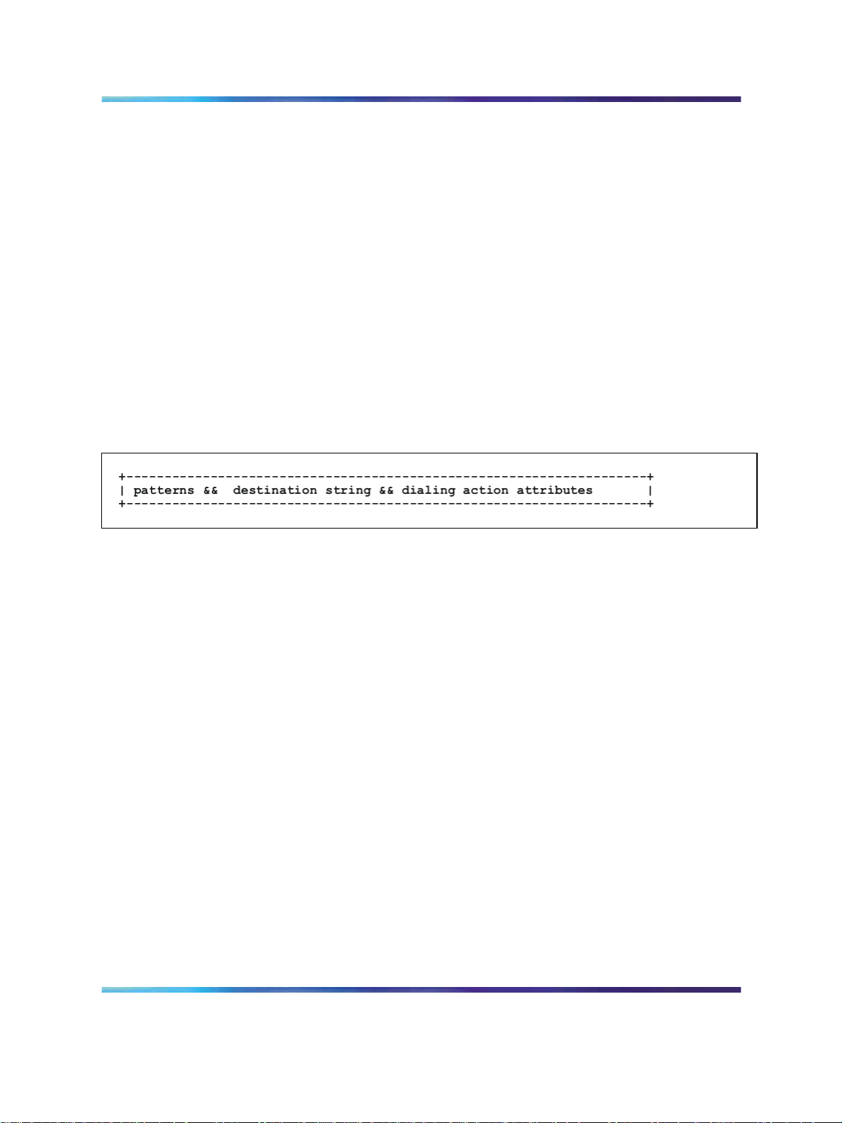
64 Configure the provisioning server
$3="."
$4="com"
$5="Nortel.com"
$t=10000 (default timer is 10 seconds)
$a=Nortel.com
The second section of dialing plan contains the digit map. The digit map
section has three subsections that are divided by a separator of two
ampersands (&&).
Figure 9 Sample dialing plan digit map section
The first part of a dialing plan contains a pattern defined with DRegex, which
is used for matching the dialed number. The patterns are separated by the
pipe (|) sign. The second part contains the result string used in the dial step.
The third part defines the parameters used by UA in dialing action.
The following parameter is currently defined:
t=xxxx: After this timer expires, the number entered is automatically dialed.
The timer starts after the first digit is entered and after it expires, the
collected digits are automatically dialed out. xxxx is a decimal number in
msec. The default timer is used when t is not specified in the digit map.
For example:
X{4} && sip:$$; phone-context=nortel.com;user=phone && t=7000
When the user presses any 4 digits, such as 4567, the following SIP URIs
are generated because of the translation rule:
Sip:4567; phone-context=nortel.com;user=phone. The timeout of stopping
the collection of digits is 7 seconds.
SIP Firmware Release 2.0 for IP Phone 1140E Administration
Copyright © 2008, Nortel Networks
.
NN43113-300 03.09 Standard
15 September 2008
Page 65

Create the Dialing Plan file on the provisioning server 65
The pound sign (#) at the end of the digit map causes the IP Phone 1140E
to dial the matched dialing plan immediately.
DRegex
The Digit Regular Expression (DRegex) syntax is a telephony-oriented
mapping of Portable Operating System Interface (POSIX) Extended Regular
Expressions (ERE). Users must take care not to confuse the DRegex syntax
with POSI EREs as they are not identical. In particular, there are many
features of POSIX EREs that DRegex does not support. The dialing plan
uses DRegex instead of ERE. The following rules demonstrate the use
of DRegex.
SIP Firmware Release 2.0 for IP Phone 1140E Administration
Copyright © 2008, Nortel Networks
.
NN43113-300 03.09 Standard
15 September 2008
Page 66
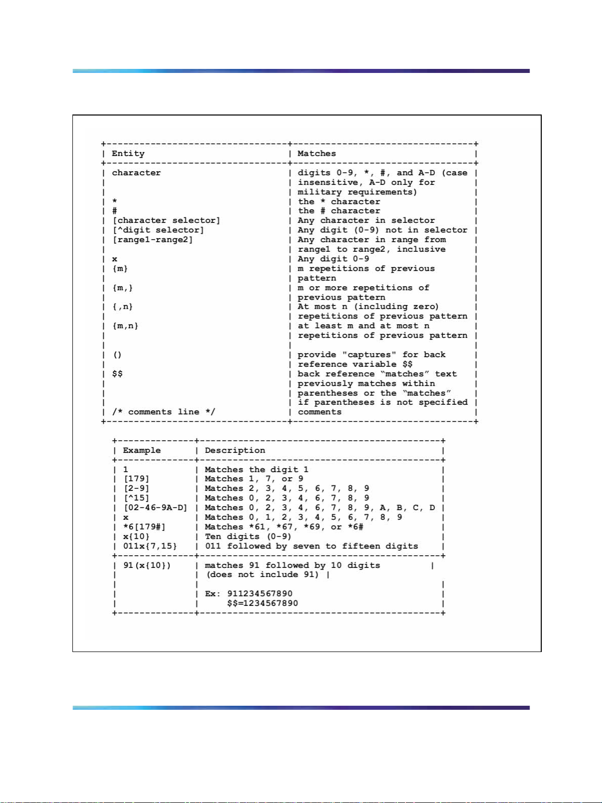
66 Configure the provisioning server
Figure 10 DRegex rules
SIP Firmware Release 2.0 for IP Phone 1140E Administration
Copyright © 2008, Nortel Networks
.
NN43113-300 03.09 Standard
15 September 2008
Page 67

Downloadable WAV files
It is possible to customize the ring tones on the IP Phone 1140E with
SIP Firmware. Up to five special ring tones can be downloaded from the
provisioning server and stored on the IP Phone 1140E. The end user can
select which ring tone they would like to implement.
In order to download these special files, the files must reside on the
provisioning server and be specified in the SIP provisioning file. For more
information, see "Download the SIP Firmware to the provisioning server"
(page 30). The WAV files have a maximum size of 512 KB each for the IP
Phone 1140E.
The file format is restricted to ITU-T A-law or u-law (8.0 kHz, 8-bit, mono
or 16.0 kHz, 16 bit mono).
After the WAV files are downloaded to the IP Phone 1140E, the WAV file
names appear in Pref, Audio, Tones, Ring Pattern(1 to 8 are standard ring
tones, and 9 and above are WAV ring tones) and the WAV ring tones can
then be selected to replace the standard ring tones.
Downloadable WAV files 67
For further information about downloadable WAV files, see the SIP Firmware
Release 2.0 for IP Phone 1140E User Guide (NN43113-101).
SIP Firmware Release 2.0 for IP Phone 1140E Administration
Copyright © 2008, Nortel Networks
.
NN43113-300 03.09 Standard
15 September 2008
Page 68

68 Configure the provisioning server
SIP Firmware Release 2.0 for IP Phone 1140E Administration
Copyright © 2008, Nortel Networks
.
NN43113-300 03.09 Standard
15 September 2008
Page 69

Configure the DHCP server
Use DHCP to provide partial Device Settings or full Device Settings, as well
as to automatically provide Voice VLAN IDs.
Table 8
Characteristics of Partial DHCP mode and Full DHCP mode
Partial DHCP mode Partial DHCP mode retrieves the following network
parameters from the DHCP server: IP address, subnet
mask, and default gateway configuration for the IP
Phone 1140E.
Full DHCP mode As well as those parameters retrieved in Partial DHCP
mode, Full DHCP also retrieves the following from the
DHCP server: DNS server and Provisioning Server.
Auto VLAN Discovery Auto VLAN Discovery retrieves the Voice VLAN ID for
the IP Phone 1140E with SIP Firmware.
Partial DHCP mode
After the IP Phone 1140E with SIP Firmware is configured to operate
in Partial DHCP mode, the DHCP server does not need any special
configuration to support an IP Phone 1140E with SIP Firmware. The IP
Phone 1140E with SIP Firmware receives the following Device Settings
parameters from the DHCP server in the following table:
69
Table 9
DHCP options in Partial DHCP mode
Parameter requested by the
IP Phone 1140E
Subnet mask The subnet mask of the IP
Phone 1140E.
Router and gateways IP address of the default
gateway of the IP Phone
1140E.
SIP Firmware Release 2.0 for IP Phone 1140E Administration
NN43113-300 03.09 Standard
Copyright © 2008, Nortel Networks
.
Description
15 September 2008
DHCP server option
1
3
Page 70

70 Configure the DHCP server
Lease time Implementation varies
according to DHCP server
configuration.
Renewal time Implementation varies
according to DHCP server
configuration.
Rebinding interval Implementation varies
according to DHCP server
configuration.
Partial DHCP is the response from a DHCP server that is not configured
to recognize the Nortel-specific Vendor Class Identifier in option 60
(Nortel-SIP-Phone-A). After the IP Phone 1140E is configured to operate
in Partial DHCP mode, the DHCP server needs no special configuration to
support an IP Phone 1140E. Using Partial DHCP, an IP Phone 1140E can
obtain its IP address, subnet mask, and gateway IP address. The remainder
of the configuration information is manually entered on the IP Phone 1140E.
This includes the DNS server IP and the Provisioning server address and
protocol.
Full DHCP mode
The DHCP server requires special configuration in Full DHCP mode. The IP
Phone 1140E with SIP Firmware obtains Device Settings parameters from
specially configured DHCP servers.
51
58
59
The IP Phone 1140E with SIP Firmware requests the following Device
Settings parameters from the DHCP server:
• IP address configuration for the IP Phone 1140E
•
subnet mask for the IP Phone 1140E IP address
•
default gateway for the IP Phone 1140E subnet
• DNS server
•
Provisioning Server
It is also possible to obtain the DNS IP automatically using Full DHCP mode
without any special configuration of the DHCP server. This means that there
is no need to configure the Nortel-specific Vendor Class Identifier (Option
60) on the DHCP server. However, the provisioning server address needs
to be manually defined within the Device Settings menu. This configuration
requires toggling to Partial DHCP mode to define the provisioning server
address and toggling back to Full DHCP mode after this is complete.
SIP Firmware Release 2.0 for IP Phone 1140E Administration
Copyright © 2008, Nortel Networks
.
NN43113-300 03.09 Standard
15 September 2008
Page 71

Configure the DHCP server to support Full DHCP mode
SIP IP Phone class identifier
A Nortel-SIP-Phone-aware DHCP server is needed for Full DHCP mode.
For Full DHCP mode, the DHCP server requires special configuration.
After the DHCP server is configured to recognize the IP Phone 1140E with
SIP Firmware as a unique IP Phone, the DHCP server can treat the IP
Phone 1140E differently than other DHCP IP Phones. An IP Phone-aware
DHCP server can automatically configure Nortel IP Phones by sending all
information that the IP Phone requires.
The IP Phone 1140E and the DHCP server communicate using a unique
class identifier. After the IP Phone 1140E first sends the DHCP DISCOVER,
it includes the Nortel-SIP-Phone-A ASCII string within the Vendor Class
Identifier (Option 60). The DHCP server recognizes this special Vendor
Class Identifier (Option 60) and sends back OFFER, which also includes the
same Vendor Class Identifier. This makes it possible to notify the IP Phone
1140E with SIP Firmware that the server is IP Phone-aware, and that it is
safe to accept the offer from the server.
Full DHCP mode 71
Every Nortel IP Phone 1140E with SIP Firmware fills in the Vendor Class
ID option of the DHCPDISCOVER and DHCPREQUEST messages with
the null-terminated, ASCII-encoded string Nortel-SIP-Phone-A, where A
identifies the version number of the information format of the IP Phone.
The Class Identifier Nortel-SIP-Phone-A must be unique in the DHCP
server domain.
The unique DHCP configuration is required to allow the DHCP server to
respond with a unique Option 66 parameter to the IP Phone 1140E with
SIP Firmware.
Note: The DHCP standard defines Option 66 as the bootp server
address in a string. The meaning of the bootp server address is
extended in Nortel IP Phone 1140E with SIP Firmware to include the
provisioning server address. The string in the DHCP offer for Option 66
can be
• the numeric IP address or name of the TFTP server or the URI (if
FTP or HTTP protocol is used) of the provisioning server in the
form of
<protocol>://<provisioning server URL>
SIP Firmware Release 2.0 for IP Phone 1140E Administration
Copyright © 2008, Nortel Networks
.
For example:
http://mydomain.com/SIP_phone
NN43113-300 03.09 Standard
15 September 2008
Page 72

72 Configure the DHCP server
If provisioning server authentication is required, the user credential
must be embedded in the URI in the form of
<protocol>://[<userid>:<password>@]<provisioning server
URL>[:port][/path]
For example,
ftp://www.mydomain.com/ABC or ftp://myuserid:mypass@ftp.mydo-
main.com:21/ABC
Requested Device Settings parameters
Using Full DHCP mode, a SIP IP Phone-aware DHCP server can
automatically configure Nortel SIP IP Phones by requesting a list of
configuration parameters. The IP Phone 1140E uses DHCP to request
and receive the information.
The following table lists the Device Settings parameters requested by the
IP Phone 1140E in the Parameter Request List option (Option Code 55) in
the DHCPDISCOVER and DHCPREQUEST messages. The DHCPOFFER
and the DHCPACK reply messages from the DHCP server must contain the
options in the following table.
Table 10
DHCP options in Full DHCP mode
Parameter requested by the
IP Phone 1140E
Subnet mask This is the subnet mask of the
IP Phone 1140E
Router and gateways IP address of the default
gateway of the IP Phone
1140E.
DNS server DNS Server address; only the
first one from the list is used.
Broadcast address This is the Broadcast address
of the subnet. The IP Phone
1140E automatically calculates
the Broadcast address if it is not
provided.
DNS domain Implementation varies
according to DHCP server.
Lease time Implementation varies
according to DHCP server.
Renewal time Implementation varies
according to DHCP server.
Description
DHCP server option
1
3
6
28
15
51
58
SIP Firmware Release 2.0 for IP Phone 1140E Administration
Copyright © 2008, Nortel Networks
.
NN43113-300 03.09 Standard
15 September 2008
Page 73

Full DHCP mode 73
Rebinding interval Implementation varies
according to DHCP server.
Provisioning server Used for delivering the
provisioning server IP address.
This parameter can contain
either IP address or a URL to
the provisioning server orfolder.
DHCP VLAN Auto Discovery
Configuring a server for Voice VLAN Discovery is optional. This
configuration is done in addition to any configuration done for Full DHCP
or Partial DHCP and it is required only when you are configuring the VLAN
Auto Discovery in the Device Settings menu on the IP Phone 1140E.
Auto Voice VLAN Discovery is only possible in Full and Partial DHCP mode.
VLAN Auto Discovery configuration is useful in a network with separate
Data VLAN for traffic (commonly used for PC-to-PC communication) and
Voice VLAN for VoIP traffic with different priorities.
The VLAN Auto Discovery is a two-step process:
1. DISCOVER is sent to the DHCP server for available Voice VLAN IDs.
The DHCP server sends an OFFER with the available Voice VLAN
IDs. If the Data VLAN ID has been manually provisioned in the Device
Settings of the IP Phone 1140E, DHCP DISCOVER is tagged with the
Data VLAN ID; otherwise, it is untagged.
59
66
2. DISCOVER is sent to the DHCP server for all of the DHCP required
parameters. However, this DISCOVER is tagged with the Voice VLAN
obtained in step 1.
DHCP VLAN Auto Discovery requires a Nortel-SIP-Phone-aware
DHCP server. All DHCP requests carry the Vendor Class Identifier,
Nortel-SIP-Phone-A, to allow the DHCP server to identify that the requests
are coming from an IP Phone 1140E with SIP Firmware.
DHCP Auto Discovery returns Voice VLAN IDs. The DHCP protocol
provides no standard option for VLAN ID requests. Separate DHCP
vendor-specific entry is needed for DHCP VLAN Auto Discovery to convey
the VLAN information to the IP Phone. DHCP VLAN Auto Discovery
uses one of the reserved for site-specific use DHCP options for VLAN list
retrieval. At least one of the following Nortel site-specific options must be
returned by the DHCP server as part of each DHCPOFFER and DHCPACK
message for the IP Phone to accept these messages as valid; 43, 128, 131,
144, 157, 188, 191, 205, 219, 223, 232, 247, 251.
SIP Firmware Release 2.0 for IP Phone 1140E Administration
Copyright © 2008, Nortel Networks
.
NN43113-300 03.09 Standard
15 September 2008
Page 74

74 Configure the DHCP server
After multiple VLAN IDs are returned from the DHCP server, the IP Phone
1140E tries to connect to each of the VLANs, following the order in which
VLAN IDs are specified in the DHCP option.
The format of the field for DHCP VLAN Auto Discovery is: Type, length, and
data, described in the following sections.
Type (1 octet)
To avoid the possibility of option types already being used by different
vendors, there are fourteen options types supported by the telephone. They
are: 128, 131, 144, 157, 188, 191, 205, 219, 223, 232, 247, 251, 247, and
251. Select one value from the type byte list for the DHCPOFFER response.
Nortel recommends using 232, 247, or 251. DHCP option numbers less
than 224 are reclaimed by the IETF (RFC 3942). Future changes in the
DHCP protocol can force the telephone to stop sending these option
requests. Currently, IP Phone 1140E with SIP Firmware does support the
remaining listed options to maintain backward compatibility.
Length (1 octet)
The Length value is variable. Count only the number of octets in the data
field.
Data (variable number of octets)
ASCII based format: VLAN-A:XXX+YYY+ZZZ. where, VLAN– A: uniquely
identifies this as the Nortel DHCP VLAN discovery request. Each VLAN ID
is followed by a plus (+) sign if there are more VLAN IDs or a period (.) to
terminate the string.
There are a maximum of 10 VLAN IDs that can be configured in the current
version.
Once IP Phone 1140E with SIP Firmware receives the DHCP offer
containing the site-specific Voice VLAN option, the next DHCPDISCOVERY
message is tagged with the Voice VLAN ID.
SIP Firmware Release 2.0 for IP Phone 1140E Administration
Copyright © 2008, Nortel Networks
.
NN43113-300 03.09 Standard
15 September 2008
Page 75

Physically install the IP Phone 1140E
Complete instructions to physically install the IP Phone 1140E, including
detailed figures and applicable warnings, are given in the document SIP
Firmware Release 2.0 for IP Phone 1140E User Guide (NN43113-101).
The steps for installing the IP Phone 1140E are summarized in the following
procedure.
Procedure 4 Installing the IP Phone 1140E
Step Action
75
1
Remove the stand cover. Pull upward on the center catch and
removethe stand cover. The cable routing tracks are now accessible.
2
Connect the AC power adapter (optional). Connect the adapter to
the AC adapter jack in the bottom of the IP Phone 1140E. Form a
small bend in the cable, and then thread the adapter cord through
the channels in the stand.
3
Install the handset. Connect the end of the handset cable with the
short straight section into the handset. Connect the end of the
handset cable with the long straight section to the back of the IP
Phone 1140E, using the RJ-9 handset jack. Form a small bend in
the cable, and then thread the handset cord through the channels in
the stand so that it exits behind the handset on the right side, in the
handset cord exit in the stand base.
4
Install the headset (optional). If installing a headset, plug the
connector into the RJ-9 headset jack on the back of the IP Phone
1140E, and thread the headset cord along with the handset cord
through the channels in the stand, so that the headset cord exits
the channel.
5
Install the Ethernet cable. Connect one end of the supplied Ethernet
cable to the back of the IP Phone 1140E using the RJ-45 connector
and thread the network cable through the channel.
SIP Firmware Release 2.0 for IP Phone 1140E Administration
Copyright © 2008, Nortel Networks
.
NN43113-300 03.09 Standard
15 September 2008
Page 76

76 Physically install the IP Phone 1140E
6
7
8
9
10
Install the Ethernet cable connecting the PC to the IP Phone 1140E
(optional). If connecting PC Ethernet through the IP Phone 1140E,
connect one end of the PC Ethernet cable to the IP Phone 1140E
using the RJ-45 connector and thread it through the channel.
Connect the other end to the LAN connector on the back of the PC.
Install additional cables. If applicable, plug in optional USB devices.
Connect the Ethernet cable to the LAN Ethernet connection. If using
an AC power adapter, plug the adapter into an AC outlet.
Wall-mount the IP Phone 1140E (optional). The IP Phone 1140E
can be mounted either by: (method A) using the mounting holes on
the bottom of the IP Phone 1140E stand, or (method B) using a
traditional-style wall-mount box with RJ-45 connector and 15-cm
(6-inch) RJ-45 cord (not provided).
Replace the stand cover. Ensure that all cables are neatly routed
and press the stand cover into place until a click is heard.
Put the IP Phone 1140E in the wall-mount position (optional). If the
IP Phone 1140E is to be mounted on the wall, put it in the wall-mount
position by holding the tilt lever and pressing the IP Phone 1140E
towards the base until the IP Phone 1140E is parallel with the base.
Release the tilt lever and continue to push the IP Phone 1140E
towards the base until an audible click is heard. Ensure the IP Phone
1140E is securely locked in position.
SIP Firmware Release 2.0 for IP Phone 1140E Administration
Copyright © 2008, Nortel Networks
.
—End—
NN43113-300 03.09 Standard
15 September 2008
Page 77

The following figure shows the connections on the IP Phone 1140E.
Figure 11 IP Phone 1140E connections
Physically install the IP Phone 1140E 77
SIP Firmware Release 2.0 for IP Phone 1140E Administration
Copyright © 2008, Nortel Networks
.
NN43113-300 03.09 Standard
15 September 2008
Page 78

78 Physically install the IP Phone 1140E
SIP Firmware Release 2.0 for IP Phone 1140E Administration
Copyright © 2008, Nortel Networks
.
NN43113-300 03.09 Standard
15 September 2008
Page 79

Upgrade and convert the IP Phone
1140E firmware
Introduction
This chapter describes how to upgrade an IP Phone 1140E with UNIStim
firmware to SIP firmware.
In order to upgrade an IP Phone 1140E with UNIStim firmware, first
determine if you have the minimum UNIStim firmware release on the IP
Phone (0625C39). If your IP Phone 1140E is installed with the minimum
version of UNIStim firmware, proceed to the section "Convert UNIStim
Firmware to SIP Firmware on the IP Phone 1140E" (page 87). If your IP
Phone 1140E is not installed with the minimum version of UNIStim firmware,
proceed to the section "Upgrade to the minimum UNIStim Firmware" (page
81).
To convert the firmware on the IP Phone 1140E from SIP to UNIStim, see
the section "Maintenance and troubleshooting" (page 149).
79
Upgrade the SIP Firmware on the IP Phone 1140E
Use the following procedures to upgrade existing SIP Firmware to new SIP
Firmware on the IP Phone 1140E.
Download the SIP Firmware to the provisioning server
To download the SIP Firmware, follow the steps in the next procedure.
Procedure 5 Downloading SIP Firmware for the IP Phone 1140E from the Nortel Web site
Step Action
1
2
SIP Firmware Release 2.0 for IP Phone 1140E Administration
Copyright © 2008, Nortel Networks
.
Go to w
Log on to the Nortel Web site with a valid Nortel User ID and
Password.
The Technical Support page appears.
ww.nortel.com/support.
NN43113-300 03.09 Standard
15 September 2008
Page 80

80 Upgrade and convert the IP Phone 1140E firmware
3
4
Enter IP Phone 1140E in the Knowledge and Solution Engine box.
Select Software in the All types scroll down menu.
5 Press the gray arrow at the end of the Knowledge and Solution
Engine box to obtain the Search Results.
6
From the Search Results, select the appropriate version of the SIP
Firmware for the IP Phone 1140E, for example, SIP IP Phone 1140E
Release 0625C39D26.bin.
7
Place the selected firmware on the provisioning server.
Modify the SIP provisioning file
Use the following procedure to modify the SIP provisioning file, which exists
on the provisioning server.
Procedure 6
Modifying the SIP provisioning file
Step Action
—End—
1
Under the firmware [FW] section of the SIP Provisioning file,
increase the VERSION number (for example 06A5C39d26).
2
Under the firmware [FW] section of the SIP Provisioning file, modify
the FILENAME of the new file you want to upload to the IP Phone
1140E.
3
Invoke the upgrade mechanism.
Use one of the next three methods to invoke a firmware upgrade on
the IP Phone 1140E with SIP Firmware.
1. Power off and power on the IP Phone 1140E.
2. Select Services, System, Check For Updates on the IP Phone
1140E.
3. Allow for an automatic check for updates to occur. (See
AUTO_UPDATE under "Feature configuration commands " (page
42)).
Any of these actions causes the IP Phone 1140E to contact the
provisioning server and attempt to read the Provisioning file. A Soft
Reset (Srvcs, System, Reset Phone) does not cause the IP Phone
1140E to retrieve the Provisioning file and hence does not cause a
firmware upgrade.
SIP Firmware Release 2.0 for IP Phone 1140E Administration
Copyright © 2008, Nortel Networks
.
NN43113-300 03.09 Standard
15 September 2008
Page 81

Upgrade to the minimum UNIStim Firmware 81
—End—
Upgrade to the minimum UNIStim Firmware
The IP Phone 1140E can be ordered with UNIStim Firmware installed or
with SIP Firmware installed. You can convert the firmware on an IP Phone
1140E from UNIStim to SIP. To successfully convert the firmware from
UNIStim to SIP, the UNIStim Firmware version on your IP Phone 1140E
must be 0625C39 or higher.
Identify the current version of UNIStim Firmware
For a new IP Phone 1140E, follow Procedure 7 "Checking the UNIStim
Firmware version on a new IP Phone 1140E" (page 81) to determine the
version number of the UNIStim Firmware on an IP Phone 1140E.
For an IP Phone 1140E already in use, follow Procedure 8 "Checking the
UNIStim Firmware version on an IP Phone 1140E already in use" (page
82) to determine the version number of UNIStim Firmware on an IP Phone
1140E.
Procedure 7 Checking the UNIStim Firmware version on a new IP Phone 1140E
Step Action
1
After assembling the IP Phone 1140E and turning it on, the display
on the IP Phone 1140E goes through the following sequence:
•
Nortel splash screen appears
•
Nortel sonic sound plays
•
Nortel banner appears
Following the Nortel banner, the firmware version appears in the
display (F/W version).
2
Note the UNIStim Firmware version number and write it down.
Compare the version number to the minimum-required UNIStim
Firmware version (0625C39).
UNIStim Firmware version names contain numbers and letters.
Use the last three characters in a version to compare the version
of UNIStim on an IP Phone 1140E (0625C39) with the minimum
required version for the upgrade. Note that C23 is greater than C39
and C1B is less than C39.
SIP Firmware Release 2.0 for IP Phone 1140E Administration
Copyright © 2008, Nortel Networks
.
NN43113-300 03.09 Standard
15 September 2008
Page 82

82 Upgrade and convert the IP Phone 1140E firmware
If the version number is equal to or higher than 0625C39, go to
the section "Convert UNIStim Firmware to SIP Firmware on the IP
Phone 1140E" (page 87).
If the number is lower than 0625C39, go to the section "Upgrade
UNIStim Firmware to the minimum required UNIStim Firmware"
(page 84) and follow the instructions to upgrade an IP Phone 1140E
to the minimum-required version of UNIStim Firmware before a
conversion to SIP Firmware.
Procedure 8 Checking the UNIStim Firmware version on an IP Phone 1140E already in use
Step Action
—End—
1
Press the Globe/Services key on the IP Phone 1140E twice quickly.
If the admin password prompt appears, enter the password
26567*738.
The Local Tools menu appears:
Table 11
Local Tools menu
1. Preferences
2. Local Diagnostics
3. Network Configuration
4. Lock Menu
To make a selection, press the number associated with the menu
item, or use the Navigation key cluster.
SIP Firmware Release 2.0 for IP Phone 1140E Administration
Copyright © 2008, Nortel Networks
.
to scroll through the menu items. Press the Select key to select
the highlighted menu item.
NN43113-300 03.09 Standard
15 September 2008
Page 83

Upgrade to the minimum UNIStim Firmware 83
Table 12
Using the Navigation key cluster to navigate in the Local Tools menu
Key Action
Down Moves highlight down
Up Moves highlight up
Right Selected current menu item
Left Closes menu
Select key (center of cluster)
To close this menu, use the Quit key.
2
Select 2. Local Diagnostics in the Local Tools menu by pressing
the Select key in the Navigation key cluster or by pressing the
number 2.
3
Select IP Set and DHCP Information by pressing the Select key in
the Navigation key cluster or by pressing the number 2.
4 Use the down arrow in the Navigation key cluster to scroll down
the menu to Firmware Version.
5
Note the UNIStim Firmware version number and write it down.
Compare the version number to the minimum-required UNIStim
Firmware version (0625C39).
UNIStim Firmware version names contain numbers and letters.
Use the last three characters in a version to compare the version
of UNIStim on an IP Phone 1140E (0625C39) with the minimum
required version for the upgrade. Note that C23 is greater than C39
and C1B is less than C39.
Selects current menu item
If the version number is equal to or higher than 0625C39, go to the section
"Convert UNIStim Firmware to SIP Firmware on the IP Phone 1140E"
(page 87).
SIP Firmware Release 2.0 for IP Phone 1140E Administration
Copyright © 2008, Nortel Networks
.
—End—
NN43113-300 03.09 Standard
15 September 2008
Page 84

84 Upgrade and convert the IP Phone 1140E firmware
If the number is lower than 0625C39, go to the section "Upgrade UNIStim
Firmware to the minimum required UNIStim Firmware" (page 84) and follow
the instructions to upgrade an IP Phone 1140E to the minimum-required
version of UNIStim Firmware before you convert to SIP Firmware.
Upgrade UNIStim Firmware to the minimum required UNIStim Firmware
Use either of the following two methods to upgrade UNIStim Firmware.
1. UFTP download initiated by the server if the server supports this method
of upgrading UNIStim Firmware. Refer to the appropriate documentation
for your call server for instructions on using this method.
2. TFTP download on bootup.
If necessary, use the following procedure to configure the TFTP server.
Procedure 9
Configuring the TFTP server
Step Action
1
The IP Phone 1140E always executes the TFTP download at bootup
if a TFTP IP address is configured on the IP Phone 1140E after
being initiated by the telephony call server.
2
Go to the TFTP server and create the 1140e.cfg provisioning
file. The 1140e.cfg provisioning file is a clear text file. Create the
provisioning file as shown in the next table.
Table 13
Sample 1140e.cfg provisioning file
[FW]
DOWNLOAD_MODE FORCED
VERSION 0625C23
FILENAME 0625C23.bin
This configuration file forces the firmware download of 0625C23.bin.
3 Download and copy the firmware to the TFTP server directory.
To download the UNIStim Firmware for the IP Phone 1140E from
the Nortel Web site:
SIP Firmware Release 2.0 for IP Phone 1140E Administration
Copyright © 2008, Nortel Networks
.
1. Go to w
ww.nortel.com/support.
2. Log on to the Nortel Web site with a valid Nortel User ID and
Password.
NN43113-300 03.09 Standard
15 September 2008
Page 85

Upgrade to the minimum UNIStim Firmware 85
The Technical Support page appears.
3. Enter IP Phone 1140E in the Knowledge and Solution Engine
box.
4. Select SOFTWARE in the ALL TYPES scroll down menu.
5. Press the gray arrow at the end of the Knowledge and Solution
Engine box to obtain the Search Results.
6. From the Search Results, select the appropriate version of
the UNIStim Firmware for the IP Phone 1140E, for example, IP
Phone 1140E Release 0625C23
7. Place the selected firmware in the correct directory on the
provisioning server.
4
In the IP Phone 1140E Network Configuration menu, change the
TFTP server address and enter the correct TFTP server address.
This can be the provisioning server as defined in the chapter
"Configure the provisioning server" (page 29).
5
Select the Apply&Reset Context-sensitive soft key to save the
settings and reset the IP Phone 1140E.
The IP Phone 1140E downloads the firmware file. The display
shows [FW] reading…
If the download is successful, the display shows [FW] writing…
and the blue LED flashes.
After the firmware image is downloaded to the IP Phone 1140E, the
display shows [FW] finished..., the blue LED stops flashing, and the
IP Phone 1140E resets.
The IP Phone 1140E registers to the TPS with the new firmware
version.
If the upgrade is unsuccessful, see the chapter "Maintenance and
troubleshooting" (page 149) in the section Download failures.
—End—
Follow the next procedure to download the minimum required version of
UNIStim Firmware automatically through TFTP on bootup.
SIP Firmware Release 2.0 for IP Phone 1140E Administration
Copyright © 2008, Nortel Networks
.
NN43113-300 03.09 Standard
15 September 2008
Page 86

86 Upgrade and convert the IP Phone 1140E firmware
Procedure 10 Downloading UNIStim Firmware automatically through TFTP on bootup
Step Action
1
Press the Globe/Services key on the IP Phone 1140E twice quickly.
If the admin password prompt appears, enter the password
26567*738
The Local Tools menu appears:
Table 14
Local Tools menu
1. Preferences
2. Local Diagnostics
3. Device Settings
4. Lock Menu
2
Select 3. Device Settings from the Local Tools menu.
The Device Settings screen appears.
3 If you are using DHCP, select Full or Partial. If you are manually
configuring the IP address, netmask, and gateway address, select
No.
4
If the DHCP option is set to Full or Partial, the IP address is
automatically obtained.
5
6
SIP Firmware Release 2.0 for IP Phone 1140E Administration
Copyright © 2008, Nortel Networks
.
Configure the TFTP IP address within the IP Phone 1140E Device
Settings menu.
This can be the provisioning server as defined in the chapter
"Configure the provisioning server" (page 29).
Select the Apply&Reset Context-sensitive soft key to save the
settings and reset the IP Phone 1140E.
The IP Phone 1140E downloads the firmware file. The display
shows [FW] reading…
If the download is successful, the display shows [FW] writing…
and the blue LED flashes.
After the firmware image is downloaded to the IP Phone 1140E, the
display shows [FW] finished... the blue LED stops flashing, and the
IP Phone 1140E resets.
NN43113-300 03.09 Standard
15 September 2008
Page 87

Convert UNIStim Firmware to SIP Firmware on the IP Phone 1140E 87
If the upgrade is unsuccessful, see the chapter "Maintenance and
troubleshooting" (page 149) in the section Download failures.
—End—
Convert UNIStim Firmware to SIP Firmware on the IP Phone 1140E
The IP Phone 1140E can be ordered with UNIStim Firmware installed or
with SIP Firmware installed. If an IP Phone 1140E is installed with UNIStim
Firmware, it runs with SIP Firmware only if the firmware is converted from
UNIStim to SIP. If the procedure to determine the UNIStim version number
is complete, and, if necessary, the procedure to upgrade the UNIStim
Firmware is complete, an IP Phone 1140E can be converted from UNIStim
Firmware to SIP Firmware.
Compare the version number to the minimum required UNIStim Firmware
version (0625C39).
UNIStim Firmware version names contain numbers and letters. Use the
last three characters in a version to compare the version of UNIStim on
an IP Phone 1140E (0625C39) with the minimum required version for the
upgrade. Note that C23 is greater than C39 and C1B is less than C39.
The conversion must be performed using TFTP.
WARNING
The TFTP download and upgrade of the Flash memory on the
IP Phone 1140E may take a significant amount of time (possibly
up to 10 minutes). Do not unplug or reboot the IP Phone 1140E
during the process.
The next procedure explains how to download the SIP Firmware from the
Nortel Web site.
Procedure 11 Downloading SIP Firmware for the IP Phone 1140E from the Nortel Web site
Step Action
1
Go to w
2 Log on to the Nortel Web site with a valid Nortel User ID and
Password.
The Technical Support page appears.
3
Enter IP Phone 1140E in the Knowledge and Solution Engine box.
ww.nortel.com/support.
4
SIP Firmware Release 2.0 for IP Phone 1140E Administration
Copyright © 2008, Nortel Networks
.
Select SOFTWARE in the ALL TYPES scroll down menu.
NN43113-300 03.09 Standard
15 September 2008
Page 88

88 Upgrade and convert the IP Phone 1140E firmware
5
Press the gray arrow at the end of the Knowledge and Solution
Engine box to obtain the Search Results.
6
From the Search Results, select the appropriate version of the SIP
Firmware for the IP Phone 1140E, for example, IP Phone 1140E
Release 0625C39D26.bin.
7
Place the selected firmware on the provisioning server.
—End—
Follow the next procedure to convert the UNIStim Firmware to SIP Firmware
on the IP Phone 1140E.
Procedure 12 Converting UNIStim Firmware to SIP Firmware using TFTP
Step Action
1
2
Run the TFTP server (for example Tftpd32.exe).
Place firmware and configuration files in the folder of the TFTP
server (for example 1140e.img F/W file and 1140e.cfg file) that
contains the following lines:
Table 15
Sample 1140e.cfg configuration file
[FW]
DOWNLOAD_MODE AUTO
VERSION 06C25D26.bin
FILENAME 1140e.img
3
Configure the IP Phone 1140E Device Settings TFTP IP address to
the IP address where your TFTP server is running.
After you are finished the configuration, the IP Phone reboots and
sends a request to the TFTP server.
4
Select the Apply&Reset Context-sensitive soft key to save the
settings and reset the IP Phone 1140E.
The following messages display on the IP Phone 1140E as the IP
Phone 1140E cycles through the conversion process, one after the
other:
1. [FW] Reading...
2. [FW] Writing...
SIP Firmware Release 2.0 for IP Phone 1140E Administration
Copyright © 2008, Nortel Networks
.
NN43113-300 03.09 Standard
15 September 2008
Page 89

Convert UNIStim Firmware to SIP Firmware on the IP Phone 1140E 89
3. [FW] Finished...
The IP Phone 1140E then boots up with SIP Firmware.
If the conversion is unsuccessful, see the chapter "Maintenance
and troubleshooting" (page 149).
1. TFTP file transfer takes approximately 15 seconds.
2. File writing takes 2.5 minutes. The IP Phone 1140E displays the message [FW] writing… and
the blue Data Waiting LED flashes.
3. After the new SIP Firmware writing is finished, the blue LED stops flashing and the telephone
displays [FW] finished and then reboots.
4. The first time the SIP Firmware boots, the SIP Firmware performs a Flash File System conversion
that takes 2.5 minutes.
—End—
SIP Firmware Release 2.0 for IP Phone 1140E Administration
Copyright © 2008, Nortel Networks
.
NN43113-300 03.09 Standard
15 September 2008
Page 90

90 Upgrade and convert the IP Phone 1140E firmware
SIP Firmware Release 2.0 for IP Phone 1140E Administration
Copyright © 2008, Nortel Networks
.
NN43113-300 03.09 Standard
15 September 2008
Page 91

Voice Quality Monitoring
Feature overview
Proactive Voice Quality Monitoring (PVQMon or VQMon) allows the IP
Phone 1140E with SIP Firmware to report voice quality statistics to a server
in the network. The IP Phone 1140E with SIP Firmware collects various
voice quality statistics, for example, packet loss, and sends the voice quality
statistics to the server at regular intervals during a call. A subset of these
statistics is also available for the user to view on the IP Phone 1140E by
selecting the Audio softkey and then the Monitor Audio Quality menu
item.
VQMon set-up
Configure the following parameters on the IP Phone 1140E with SIP
Firmware to connect to the server and send the PVQMon statistics.
1. Enable the feature. To enable the feature, configure the
VQMON_PUBLISH parameter in the device configuration file (see
"VQMon configuration commands" (page 57)).
91
2. Configure the IP address of the PVQMon server. Configure the IP
address of the PVQMon server in either of the following settings:
a. Set VQMON_PUBLISH_IP through the device configuration file (see
b. Set PVQMon IP in Device Settings (see Table 51 "PVQMon IP
3. Configure the remainder of the VQMon parameters in the device
configuration file (see "VQMon configuration commands" (page 57)).
These parameters provide threshold information to the IP Phone 1140E
with SIP Firmware. A report is sent to the server when these thresholds
are exceeded.
SIP Firmware Release 2.0 for IP Phone 1140E Administration
Copyright © 2008, Nortel Networks
.
"VQMon configuration commands" (page 57)).
configuration" (page 121))
NN43113-300 03.09 Standard
15 September 2008
Page 92

92 Voice Quality Monitoring
Server set-up
The IP Phone 1140E with SIP Firmware works with Telchemy server
software. The name of the software is SQmediator and is available through
Telchemy (w
1.0.
How VQMon works
The IP Phone 1140E with SIP Firmware gathers statistics about the current
call when VQMon is enabled. Statistics are also gathered regarding
the quality metrics of the current call. The call-related statistics contain
condensed information about the SIP Session Description Protocol (SDP),
the Call ID, the local and remote address, voice quality-related statistics,
Zulu times for start-time and the time the report was sent.
The voice quality-related statistics include jitter, packet loss, delay, burst gap
loss, listening R-factor, R-LQ, R-CQ, MOS-LQ and MOS-CQ. See Table
16 "Glossary of RTCP XR metrics" (page 92). More information on each
of these metrics is provided in RFC3611 “RTP Control Protocol Extended
Reports (RTCP XR)”.
ww.telchemy.com). The minimum version required is release
When the IP Phone 1140E detects that a particular voice quality metric has
exceeded a threshold (defined in the device configuration file), the IP Phone
sends a message to the server indicating that there is an issue. If the issue
persists then the IP Phone reports another message indicating that there is
an exceeded value at regular intervals. This happens continuously until the
voice quality metric falls below the threshold value. As well, the IP Phone
can send regular reports of the voice quality at time intervals defined in
the device configuration file.
Table 16
Glossary of RTCP XR metrics
Burst A period of high packet losses and / or discards.
A burst is calculated in milliseconds.
Conversational R-factor Voice quality metric based on burst packet loss
and vocoder selection.
Delay One way delay which includes end-to-end delay,
jitter buffer delay and packetization delay. Delay
is calculated in milliseconds.
Inter-arrival jitter The variation in packet arrival times due to
transmission (routing, queuing delay) through the
network. Jitter is calculated in milliseconds.
Listening R-factor Voice quality metric based on burst packet loss,
transmission delay and burst loss.
SIP Firmware Release 2.0 for IP Phone 1140E Administration
Copyright © 2008, Nortel Networks
.
NN43113-300 03.09 Standard
15 September 2008
Page 93

How VQMon works 93
MIU Media Information Unit. MIU is a concept from
VQMon. An MIU can be any size down to a 10
millisecond (8 sample) block. An MIU means a
frame in the i200x implementation.
MOS Mean Opinion Score. A subjective measurement
of the voice quality of a voice call.
MOS_CQ The VQMon conversational quality MOS score
calculated for a call channel.
MOS_LQ The VQMon listening quality MOS score
calculated for a call channel.
Packet loss rate The percentage of total packets loss versus
packets received.
R-factor A measurement of voice quality based on
network impairments including burst packet
loss, delay and encoding/decoding algorithm
selection.
End of call report
The SIP phone sends a report using VQMON Publish message to the
proxy. The proxy redirects the publish ID described within the report.
End of call report is always generated if VQMON is enabled SIP phones
do not negotiate or exchange messages with the device defined using
PUBLISH_IP options.
Session interval report
The SIP phone can send voice quality reports at time intervals defined in
the device configuration file. The minimum and default time interval is 60
seconds. If SIP phones send session interval reports more frequently, then
a threshold violation has occurred.
Alert interval report
When a SIP phone detects that a voice quality metric has exceeded a
threshold, the SIP phone initiates a timer which sends a message to the
server every 5 seconds. When all voice quality metrics fall below the
threshold values, the SIP phone stops sending VQMON Publish messages
with the report. The alert interval report does not differ from the session
interval reports or end of call reports.
SIP Firmware Release 2.0 for IP Phone 1140E Administration
Copyright © 2008, Nortel Networks
.
NN43113-300 03.09 Standard
15 September 2008
Page 94

94 Voice Quality Monitoring
SIP Firmware Release 2.0 for IP Phone 1140E Administration
Copyright © 2008, Nortel Networks
.
NN43113-300 03.09 Standard
15 September 2008
Page 95

Device Settings on the IP Phone 1140E with SIP Firmware
ATTENTION
An IP Phone 1140E with SIP Firmware displays different menus than the menus
displayed on an IP Phone 1140E with UNIStim Firmware.
Introduction
This chapter details how to configure the Device Settings parameters on
the IP Phone 1140E with SIP Firmware. This includes items such as the
IP address, the subnet mask, and the gateway IP address of the IP Phone
1140E.
The Device Settings parameters are listed in the following table in the
order they appear on the Device Settings menu of the IP Phone 1140E
with SIP Firmware. Read the section at the end of this chapter that explains
how to provision the Device Settings parameters. If you are familiar with
the Device Settings parameters, skip the last section in the chapter and
proceed to the provisioning instructions.
95
Table 17
Parameters in Device Settings menu
Enable 802.1x (EAP)
Device ID
Password
Enable 802.1ab (LLDP)
DHCP
SET IP
Net Mask
SIP Firmware Release 2.0 for IP Phone 1140E Administration
Copyright © 2008, Nortel Networks
.
No
Partial
Full
NN43113-300 03.09 Standard
15 September 2008
Page 96

96 Device Settings on the IP Phone 1140E with SIP Firmware
Gateway
DNS IP1
DNS IP2
Ntwk Port Speed
Auto
10BT
100BT
Ntwk Port Duplex
Auto
Force Full
Force Half
Disable Voice 802.1Q
Voice VLAN
No VLAN
DHCP
LLDP VLAN Name
LLDP MED
Manual
VLAN Filter
Ctrl Priority bits
Auto
0-7
Media Priority bits
Auto
0-7
Disable PC Port
PC Port Speed
Auto
10BT
100BT
PC Port Duplex
Auto
Disable Data 802.1Q
SIP Firmware Release 2.0 for IP Phone 1140E Administration
Copyright © 2008, Nortel Networks
.
Force Full
Force Half
NN43113-300 03.09 Standard
15 September 2008
Page 97

Data VLAN
No VLAN
LLDP VLAN NAME
Manual (value
from 1 to 4094)
Data Priority bits
Auto
0-7
PC-Port Untag all
Cached IP
Ignore GARP
Provisioning
Server URL
Protocol
Introduction 97
TFTP
FTP
PVQMon IP
NAT Traversal
HTTP
Device ID
Password
NAT Signal
None
SIP Ping
STUN
NAT Media
None
STUN
NAT TTL
STUN S1 IP
STUN S2 IP
SIP Firmware Release 2.0 for IP Phone 1140E Administration
Copyright © 2008, Nortel Networks
.
NN43113-300 03.09 Standard
15 September 2008
Page 98

98 Device Settings on the IP Phone 1140E with SIP Firmware
802.1x (EAP) Port-based network access control
Extensible Authentication Protocol (EAP) supports multiple authentication
methods and represents a technology framework that facilitates the
adoption of Authentication, Authorization, and Accounting (AAA) schemes,
such as Remote Authentication Dial In User Service (RADIUS). RADIUS
is defined in RFC 2865. The IP Phone 1140E with SIP Firmware supports
only the MD5 authentication method.
802.1x defines the following three roles:
1. Supplicant—an IP Phone that requires access to the network to use
network services.
2. Authenticator—the network entry point to which the supplicant physically
connects (typically a Layer 2/3 switch). The authenticator acts as
the proxy between the supplicant and the authentication server. The
authenticator controls access to the network based on the authentication
status of the supplicant.
3. Authentication server—performs authentication of the supplicant.
Enable and disable Network-level authentication through the EAP
configuration menu.
Authorization
If 802.1x is configured and the IP Phone 1140E is physically connected to
the network, the IP Phone 1140E (supplicant) initiates 802.1x authentication
by contacting the Layer 2/3 switch (authenticator). The IP Phone 1140E
also initiates 802.1x authentication after the Ethernet connection (network
interface only) is restored following a network link failure.
However, if the IP Phone 1140E resets, it assumes the Layer 2 link has
remained in service and is authenticated.
The IP Phone 1140E fails to authorize if the DeviceID and the IP Phone
1140E passwords do not match the DeviceID and IP Phone 1140E
passwords provisioned on the RADIUS Server. The Layer 2 switch
(authenticator) locks out the IP Phone 1140E and network access is denied.
If this happens during reauthorization, all telephone services are lost. The
connected PC operates as normal.
Device ID
The Device ID is for use with the 802.1x (EAP) protocol. If the 802.1x (EAP)
is not used, then there is no prompt to enter the Device ID.
Password
The Password is for use with the 802.1x (EAP) protocol. If the 802.1x (EAP)
is not used, there is no prompt to enter the Password.
SIP Firmware Release 2.0 for IP Phone 1140E Administration
Copyright © 2008, Nortel Networks
.
NN43113-300 03.09 Standard
15 September 2008
Page 99

Introduction 99
802.1ab Link Layer Discovery Protocol
802.1ab Link Layer Discovery Protocol (LLDP) is a standard for discovering
the physical topology between neighboring devices. 802.1ab LLDP defines
a standard method for Ethernet network devices, such as switches, routers,
and IP Phones to advertise information about themselves to other nodes
on the network and to store the information they discover in a Management
Information Base (MIB).
802.1ab (LLDP) takes advantage of the VLAN Name and Network Policy
TLVs, and provides an automatic configuration of the phone network policy
parameters. Key parameters, such as VLAN ID, L2 priority, and DSCP
values are received from the switch and are automatically configured in
the phone.
802.1ab Link Layer Discovery Protocol (LLDP) provides the following
functionality
•
Periodic transmission of advertisements containing device information,
device capabilities and media specific configuration information to
neighbors attached to the same network.
•
Reception of LLDP advertisements from its neighbors.
•
Implementation of behavioral requirements specified by Link Layer
Discovery Protocol Media Endpoint Discovery (LLDP-MED).
•
Storage of received data in local data structures, for example, in MIB
modules.
TLVs
The information fields in each MIB are contained in a Link Layer Discovery
Protocol Data Unit (LLDPDU) as a sequence of short, variable-length,
information elements known as TLVs that each include type, length, and
value fields. Each LLDPDU includes several mandatory TLVs plus optional
TLVs. Optional TLVs may be inserted in any order.
The IP Phone supports both the transmit and receive LLDP mode.
Transmit direction
An LLDPDU transmitted by the IP Phone supports the following TLVs
1. Chassis ID
2. Port ID
3. Time To Live
4. End of LLDPPDU
5. Port Description
6. System Description
SIP Firmware Release 2.0 for IP Phone 1140E Administration
Copyright © 2008, Nortel Networks
.
NN43113-300 03.09 Standard
15 September 2008
Page 100

100 Device Settings on the IP Phone 1140E with SIP Firmware
7. System Capabilities
8. Port VLAN ID
9. Port And Protocol VLAN ID
10. VLAN Name
11. Protocol Identity
12. MAC/PHY Configuration Status
13. Power Via MDI
14. Link Aggregation
15. Maximum Frame Size
16. LLDP-MED Capabilities
17. Network Policy
18. Extended Power-via MDI
19. Inventory Firmware Revision
20. Inventory Manufacturer Name
21. Inventory Model Name
Receive direction
The IP Phone expects to receive the following TLVs
1. Chassis ID
2. Port ID
3. Time To Live
4. End of LLDPPDU
5. System Capabilities
6. VLAN Name
7. MAC/PHY Configuration Status
8. LLDP-MED Capabilities
9. Network Policy
10. Location Identification
Table 18
TLV formats
TLV Fields
Chassis ID Length = 6
Chassis Subtype = 5 [IP Address]
Chassis ID = IP Phone IP Address
SIP Firmware Release 2.0 for IP Phone 1140E Administration
Copyright © 2008, Nortel Networks
.
NN43113-300 03.09 Standard
15 September 2008
 Loading...