

Page 1

SIP DECT Fundamentals
A
vaya Communication Server 1000
NN43120-123, Standard 04.06
7.5
October 2012
Page 2

©
Avaya Inc.
2010
All Rights Reserved.
Notice
While reasonable efforts have been made to ensure that the
information in this document is complete and accurate at the time of
printing, Avaya assumes no liability for any errors. Avaya reserves the
right to make changes and corrections to the information in this
document without the obligation to notify any person or organization of
such changes.
Documentation disclaimer
Avaya shall not be responsible for any modifications, additions, or
deletions to the original published version of this documentation unless
such modifications, additions, or deletions were performed by Avaya.
End User agree to indemnify and hold harmless Avaya, Avaya's agents,
servants and employees against all claims, lawsuits, demands and
judgments arising out of, or in connection with, subsequent
modifications, additions or deletions to this documentation, to the
extent made by End User.
Link disclaimer
Avaya is not responsible for the contents or reliability of any linked Web
sites referenced within this site or documentation(s) provided by Avaya.
Avaya is not responsible for the accuracy of any information, statement
or content provided on these sites and does not necessarily endorse
the products, services, or information described or offered within them.
Avaya does not guarantee that these links will work all the time and has
no control over the availability of the linked pages.
Warranty
Avaya provides a limited warranty on this product. Refer to your sales
agreement to establish the terms of the limited warranty. In addition,
Avaya’s standard warranty language, as well as information regarding
support for this product, while under warranty, is available to Avaya
customers and other parties through the Avaya Support Web site:
http://www.avaya.com/support. Please note that if you acquired the
product from an authorized
and Canada, the warranty is provided to you by said Avaya reseller and
not by Avaya.
Licenses
THE SOFTWARE LICENSE TERMS AVAILABLE ON THE AVAYA
WEBSITE,
APPLICABLE
INSTALLS AVAYA SOFTWARE, PURCHASED FROM AVAYA INC.,
ANY AVAYA AFFILIATE, OR AN AUTHORIZED AVAYA RESELLER
(AS APPLICABLE) UNDER A COMMERCIAL AGREEMENT WITH
AVAYA OR AN AUTHORIZED AVAYA RESELLER. UNLESS
OTHERWISE AGREED TO BY AVAYA IN WRITING, AVAYA DOES
NOT EXTEND THIS LICENSE IF THE SOFTWARE WAS OBTAINED
FROM ANYONE OTHER THAN A V A Y A, AN A V A Y A AFFILIA TE OR AN
AVAYA AUTHORIZED RESELLER, AND AVAYA RESERVES THE
RIGHT TO TAKE LEGAL ACTION AGAINST YOU AND ANYONE
ELSE USING OR SELLING THE SOFTWARE WITHOUT A LICENSE.
BY INST ALLING, DOWNLOADING OR USING THE SOFTW ARE, OR
AUTHORIZING OTHERS TO DO SO, YOU, ON BEHALF OF
YOURSELF AND THE ENTITY FOR WHOM YOU ARE INSTALLING,
DOWNLOADING OR USING THE SOFTWARE (HEREINAFTER
REFERRED TO INTERCHANGEABL Y AS “YOU” AND “END USER”),
AGREE TO THESE TERMS AND CONDITIONS AND CREATE A
BINDING CONTRACT BETWEEN YOU AND AVAYA INC. OR THE
APPLICABLE AVAYA AFFILIATE (“AVAYA”).
Copyright
Except where expressly stated otherwise, no use should be made of
materials on this site, the Documentation(s) and Product(s) provided
by Avaya. All content on this site, the documentation(s) and the
product(s) provided by Avaya including the selection, arrangement and
design of the content is owned either by Avaya or its licensors and is
HTTP://SUPPORT.AVAYA.COM/LICENSEINFO/ ARE
TO ANYONE WHO DOWNLOADS, USES AND/OR
Avaya reseller outside of the United States
protected by copyright and other intellectual property laws including the
sui generis rights relating to the protection of databases.
modify, copy, reproduce, republish, upload, post, transmit or distribute
in any way any content, in whole or in part, including any code and
software. Unauthorized reproduction, transmission, dissemination,
storage, and or use without the express written consent of Avaya can
be a criminal, as well as a civil, offense under the applicable law.
Third-party components
Certain software programs or portions thereof included in the Product
may contain software distributed under third party agreements (“Third
Party Components”), which may contain terms that expand or limit
rights to use certain portions of the Product (“Third Party Terms”).
Information regarding distributed Linux OS source code (for those
Products that have distributed the Linux OS source code), and
identifying the copyright holders of the Third Party Components and the
Third Party Terms that apply to them is available on the Avaya Support
Web site:
Preventing toll fraud
“T
by an unauthorized party (for example, a person who is not a corporate
employee, agent, subcontractor, or is not working on your company's
behalf). Be aware that there can be a risk of toll fraud associated with
your system and that, if toll fraud occurs, it can result in substantial
additional charges for your telecommunications services.
Avaya fraud intervention
If you suspect that you are being victimized by toll fraud and you need
technical assistance or support, call Technical Service Center Toll
Fraud Intervention Hotline at +1-800-643-2353 for the United States
and Canada. For additional support telephone numbers, see the Avaya
Support Web site:
vulnerabilities with
sending mail to: securityalerts@avaya.com.
Trademarks
The trademarks, logos and service marks (“Marks”) displayed in this
site, the documentation(s) and product(s) provided by Avaya are the
registered or unregistered Marks of Avaya, its affiliates, or other third
parties. Users are not permitted to use such Marks without prior written
consent from Avaya or such third party which may own the Mark.
Nothing contained in this site, the documentation(s) and product(s)
should be construed as granting, by implication, estoppel, or otherwise,
any license or right in and to the Marks without the express written
permission of Avaya or the applicable third party.
Avaya is a registered trademark of Avaya Inc.
All other trademarks are the property of their respective owners.
Downloading documents
For the most current versions of documentation, see the Avaya Support
Web site:
Contact
Avaya provides a telephone number for you to use to report problems
or to ask questions about your product. The support telephone number
is 1-800-242-2121 in the United States. For additional support
telephone numbers, see the Avaya Web site:
support
http://www.avaya.com/support/Copyright/.
oll fraud” is the unauthorized use of your telecommunications system
http://www.avaya.com/support/. Suspected security
Avaya products should be reported to Avaya by
http://www.avaya.com/support
Avaya Support
http://www.avaya.com/
You may not
2 SIP DECT Fundamentals October 2012
Comments? infodev@avaya.com
Page 3

Contents
Chapter 1: New in this release...........................................................................................
Features....................................................................................................................................................
Revision History........................................................................................................................................
Chapter 2: Product overview.............................................................................................
Navigation.................................................................................................................................................
Overview of Avaya SIP DECT...................................................................................................................
Universal extension support......................................................................................................................
DECT Handset features............................................................................................................................
CallPilot and Message Waiting Indication support....................................................................................
SIP DECT capacity limitations..................................................................................................................
Chapter 3: Site planning and hardware deployment.......................................................
Navigation.................................................................................................................................................
Components of SIP DECT systems..........................................................................................................
Types of SIP DECT configuration.............................................................................................................
Site planning.............................................................................................................................................
System deployment...................................................................................................................................
Chapter 4: Software requirements....................................................................................
Navigation.................................................................................................................................................
Call Server and SIP Line Gateway software.............................................................................................
DAP controller software............................................................................................................................
Chapter 5: System configuration.......................................................................................
Navigation.................................................................................................................................................
Basic (simple) SIP DECT configuration with Communication Server 1000 SIP Line Gateway................
Branch Office configuration..............................................................................................................
Routed Head Quarter configuration..........................................................................................................
Routed Head Quarter Configuration with Branch Office...................................................................
Multiple-site mobility network configuration...............................................................................................
Multiple Gatekeepers Configuration.................................................................................................
Chapter 6: System administration.....................................................................................
Navigation.................................................................................................................................................
DAP manager overview............................................................................................................................
Subscription management........................................................................................................................
DAP management.....................................................................................................................................
Add a DN range........................................................................................................................................
System backup..........................................................................................................................................
Subscription export and import.................................................................................................................
DAP reboot history....................................................................................................................................
System archive..........................................................................................................................................
Handset firmware update..........................................................................................................................
Central Directory access tool....................................................................................................................
Chapter 7: System maintenance........................................................................................
Navigation.................................................................................................................................................
DAP Web interface....................................................................................................................................
C4710 DAP LED indications.....................................................................................................................
7
7
7
9
9
9
12
13
14
15
17
17
17
28
33
40
75
75
75
75
93
93
93
107
109
111
113
117
121
121
121
123
129
132
133
134
137
137
138
142
147
147
147
149
SIP DECT Fundamentals October 2012 3
Page 4

4720 DAP LED indications........................................................................................................................
DAP firmware update................................................................................................................................
Remove and replace a DAP (if a new DAP is available)..........................................................................
Remove and replace a DAP (if a new DAP is not available)....................................................................
System synchronization analysis..............................................................................................................
Export and import SIP DECT system........................................................................................................
DAP Controller deactivation......................................................................................................................
Uninstalling DAP Controller software...............................................................................................
DAP Controller software update.......................................................................................................
Troubleshooting........................................................................................................................................
If you have problems.................................................................................................................................
Appendix A: G.729 daughterboard and DAP wall mounting...........................................
Navigation.................................................................................................................................................
Mount the G.729 daughterboard...............................................................................................................
Adjusting the antenna position..................................................................................................................
Mounting the 4720 DAP on a wall.............................................................................................................
Appendix B: Location builder tool....................................................................................
Use the Location builder tool....................................................................................................................
Create a location file.................................................................................................................................
Maintenance..............................................................................................................................................
Appendix C: Site survey example.....................................................................................
Site planning example: Able-Studio..........................................................................................................
Appendix D: Deployment tool............................................................................................
Prepare the tool for deployment................................................................................................................
How the deployment tool works................................................................................................................
Using the deployment tool........................................................................................................................
Appendix E: Install the external housing..........................................................................
Installing 4720 DAP with internal antennas..............................................................................................
Installing a 4720 DAP with external antennas..........................................................................................
Installing a C4710 DAP in an external housing.........................................................................................
Installing a C4710E DAP in an external housing with an external antenna..............................................
Mounting the cabinet on a wall.................................................................................................................
Mounting the cabinet on a pole.................................................................................................................
Appendix F: Upgrade a SIPN connection to a SIPL connection.....................................
SIPL deployment.......................................................................................................................................
Convert SIPN/SIP3 TNs to SIPL UEXT TNs.............................................................................................
SIP DECT system upgrade.......................................................................................................................
Appendix G: Third Party Software.....................................................................................
SRTP.........................................................................................................................................................
TLS............................................................................................................................................................
Appendix H: DECT Handset Configurator Tool................................................................
Requirements............................................................................................................................................
Installation.................................................................................................................................................
Main operations.........................................................................................................................................
Operations with an image file...........................................................................................................
Operations with a MEM card............................................................................................................
Handset subscription........................................................................................................................
149
150
151
152
153
165
166
167
168
169
171
175
175
175
177
180
183
191
193
198
199
199
205
207
214
215
217
217
222
228
230
232
233
235
236
237
237
239
239
240
243
243
243
244
244
245
247
4 SIP DECT Fundamentals October 2012
Page 5

Feature configuration................................................................................................................................
Messaging........................................................................................................................................
Contacts...........................................................................................................................................
Settings............................................................................................................................................
Calls.................................................................................................................................................
Calendar and Accessories...............................................................................................................
Feature selection.......................................................................................................................................
Broadcast Groups.....................................................................................................................................
Appendix I: DAP multicast group membership................................................................
DECT Access Point network interface......................................................................................................
Multicast configuration..............................................................................................................................
The IGMP snooping problem....................................................................................................................
The IGMP snooping solution.....................................................................................................................
Multicast host behavior of a DAP..............................................................................................................
Appendix J: DECT Messaging and Location Service......................................................
Installation.................................................................................................................................................
Configuration.............................................................................................................................................
Index.....................................................................................................................................
249
249
250
251
253
253
253
257
259
259
260
261
261
262
267
267
268
269
SIP DECT Fundamentals October 2012 5
Page 6

6 SIP DECT Fundamentals October 2012
Page 7

Chapter 1: New in this release
The following sections describe what’
Communication Server 1000 Release 7.5.
Features on page 7
•
• Revision History on page 7
s new in this document for DECT Release 5.2 and Avaya
Features
Release 5.20.091 for Communication Server 1000 Release 7.5 introduces the following:
DECT
• additional information about G.729 codec
• new Messaging and Location Service
Revision History
Date Description
October 2012 Standard 04.06. This document is up-issued to update configuration
information for optional SIP
configuration settings.
October 2011 Standard 04.05. This document is up-issued to support SIP DECT
5.20.091 and Avaya Communication Server 1000 Release 7.5.
June 2011 Standard 04.04. This document is up-issued to support SIP DECT 5.2
and Avaya Communication Server 1000 Release 7.5.
November 2010 Standard 04.03. This document is published to support Avaya
Communication Server 1000 Release 7.5.
November 2010 Standard 04.01 and 04.02. This document is up-issued to support Avaya
Communication Server 1000 Release 7.5.
June 2010 Standard 03.01. This document is up-issued to support Avaya
Communication Server 1000 Release 7.0.
March 2010 Standard 02.02. This document is up-issued with information for SIP
DECT on SIP LINE, and to support Communication Server 1000 (CS
1000) Release 6.0.
SIP DECT Fundamentals October 2012 7
Page 8

New in this release
October 2009 Standard 02.01. This document is up-issued to reflect changes in
January 2009 Standard 01.07. This document is up-issued for Communication Server
December 2008 Standard 01.06. This document is up-issued for Communication Server
July 2008 Standard 01.05. This document is up-issued in response to change
July 2008 Standard 01.04. This document is up-issued in response to change
May 2008 Standard 01.03. This document is up-issued in response to change
March 2008 Standard 01.02. This document is up-issued in response to change
Date Description
technical content stemming from SIP
DECT 4.2, and to support
Communication Server 1000 Release 6.0.
1000 Release 5.5 with editorial changes.
1000 Release 5.5, in response to change requests for content related to
SIP DECT 4.1.
requests.
requests.
requests.
requests.
February 2008 Standard 01.01. This is a new document issued to support
Communication Server 1000 Release 5.5. Some of the information in this
new document was previously contained in the following document:
DECT Fundamentals, NN43120-114.
8 SIP DECT Fundamentals October 2012
Comments? infodev@avaya.com
Page 9

Chapter 2: Product overview
This section describes the capabilities, configuration, and design of
Communication Server 1000 (Avaya CS 1000).
Navigation
• Overview of Avaya SIP DECT on page 9
Overview of Avaya SIP DECT
ou can use Avaya Session Initiation Protocol (SIP) Digital Enhanced Cordless
Y
T elecommunications (DECT) to move without restriction about your work site while conducting
telephone conversations, using wireless handsets. The Avaya SIP DECT system includes one
or more DECT access points (DAPs or basestations) connected to the TLAN.
The system supports the following connection types for SIP DECT configuration:
• SIPL configuration, which uses SIP Line Gateway
A minimal SIP DECT system has the following main components.
Avaya SIP DECT for Avaya
• Call Server
• SIP Line Gateway
• PC with DAP controller software installed
• DAP
• DECT Handset
Use the following tools to configure SIP DECT.
• Element Manager or overlay program for Call Server
• Element Manager for SIP Line Gateway
• IP DECT Configurator—used to enter SIP DECT configuration
• DAP Manager (IP DECT Manager)—a Web interface used for SIP DECT administration
tasks such as adding a handset or removing a subscription.
The IP DECT Configurator and the DAP manager IP DECT are available as a part of the DAP
controller software package.
SIP DECT Fundamentals October 2012 9
Page 10

Product overview
The following software releases are required for the main system components:
You can connect IP Deskphones to the TLAN, and you can connect TDM telephones to the
Call Server, Voice Gateway Media Cards, and other required cards in the Call Server. Use
Voice Gateway Media Cards for IP-to-TDM calls and for conference calls involving IP
Deskphones or DECT Handsets on basestations. The configuration can also include a PC with
DECT Messenger to provide the DECT messaging service on SIP DECT.
Use the Dynamic Host Control Protocol (DHCP) server or the Trivial File Transfer Protocol
(TFTP) server unless you use a DAP configuration without DHCP or TFTP. You can configure
the system to use two separate servers: one for DHCP and the other for TFTP. If the system
requires DAP configuration without DHCP or TFTP, the DHCP or TFTP server is required
during installation or configuration changes.
The following figure shows a general SIP DECT configuration.
Call Server, Release 7.5 or later
•
• SIP Line Gateway application, Release 7.5 or later
• DAP software 4910b524.dwl or later
• DAP controller 5.2 or later (PC software)
10 SIP DECT Fundamentals October 2012
Comments? infodev@avaya.com
Page 11

Overview of Avaya SIP DECT
Figure 1: SIP DECT configuration
ou can install the DHCP or TFTP services, DECT Messenger , and DAP controller on a single
Y
server or PC. However, you can also install them on separate servers to enhance performance
or facilitate administration.
Y ou connect the DAP to the Communication Server 1000 (CS 1000) using the SIP Line trunks
that you configure for SIP Line Gateway
Each DAP communicates with the subscribed DECT handsets in the coverage area, and each
DAP interacts with the CS 1000 and with other configured DAPs in the company network.
You can run SIP DECT on the following configurations:
• Communication Server 1000M or Communication 1000E
• SIP Line Gateway
SIP DECT Fundamentals October 2012 11
Page 12

Product overview
Universal extension support
Handsets subscribed on DAPs are external to CS 1000. The CS 1000 does not control
DECT
the state of DECT Handsets. Therefore, the CS 1000
• cannot detect individual key presses on DECT Handsets
• cannot control cadences on DECT Handsets
• cannot control the DECT Handset display content
A DECT Handset subscribed on a DAP cannot use the same range of features available to
analog, digital, or UNIStim IP Deskphones on the CS 1000.
The Universal Extension (UEXT) feature on the Call Server provides Configuration and status
information for subscribed DECT Handsets.
There is limited support for Associated Telephone (AST) or Computer-Telephone Integration
(CTI) capabilities on SIPL for Presence on OCS.
Each DECT Handset has a local Directory Number (DN) in CS 1000. Use this local DN to
subscribe the corresponding DECT Handsets on the SIP DECT system through DAP Manager.
DAP manager is available on the server where you installed the DAP controller.
Configure the UEXT associated with a DECT Handset as follows:
• For the Primary DN of the UEXT (key 0 SCR), enter the local DN associated with the
DECT Handset.
• For SIPL configuration for the Target DN of the UEXT (key 1 HOT U), enter the digits of
the User agent prefix (SIP Line configuration item) plus the local DN of the DECT
Handsets.
A UEXT corresponding to a DECT Handset on the SIP DECT system reflects the idle or busy
status of the associated handset by a check for a call processed between the handset and a
DAP.
The Integrated SIP DECT provides the following UEXT features.
• Make and receive simple calls
• Call Hold. Only one active call and one call on hold can exist for a handset
• Consultative or Announced Call Transfer
• Blind Call Transfer
• Conference call participation if another party adds the DECT Handset to the conference
• Start a three-way call
12 SIP DECT Fundamentals October 2012
Comments? infodev@avaya.com
Page 13

DECT Handset features
• Calling Line ID (CLID) and Calling Party Name Display (CPND) for simple calls not
involving call transfer
• CLID and CPND for an internal line (digital or IP phone with display) calling to or receiving
a call from a DECT Handset
• Sending DTMF tones through the established connection to interact with the called line
(party), for example, to work with CallPilot
• Support for a voice mailbox on CallPilot and Message Waiting Indication (MWI)
• Call Forward No Answer
• Call Forward By Time of Day
• Call Forward Busy
• Hunting
• Call Restrictions applicable to a UEXT
• Twinned configuration (typically a desk phone plus a DECT Handset)
• Call Waiting
DECT Handset features
The user of a DECT
• Make calls to DNs except restricted or blocked DNs.
• Receive and answer calls from the Call Server. If CPND is available, the name of the
caller and DN appear on the Handset display. The position and appearance of the name
DN on the display depend on the firmware installed on the Handset. You must configure
the required CLS in the UEXT block (CNIA/CNDA/DNDA) and username in LD 95. SIP
DECT also supports CLID restrictions (for example, CLBA, NAMD, DDGD). SIP DECT
Handsets support display update during established calls; this allows SIP DECT on SIP
Line to show a new display name for the connected party. During transfers (both Blind
and Consultative), this provides the new party’s name on the DECT Handset after the
transfer is complete. The display name is taken from the CPND block created for SIPL
UEXT.
Note:
During a transfer
• Place the active call on hold by pressing the R key on the Handset. Return to the held
call by pressing the R key . If a call is on hold, another call can be made from the Handset.
After the second call is established, the user can switch between the two calls with the R
key.
Handset subscribed on SIP DECT can perform the following actions:
, only the display name updates, not the connected number.
SIP DECT Fundamentals October 2012 13
Page 14

Product overview
• Transfer a call to another DN
- To perform a Blind Transfer, place the current call on hold, call the required DN, and
immediately release from the call.
- To perform a Consultative Transfer, place the current call on hold, call the required
DN, wait for the answer, and release the call after the DN answers.
• Press digit keys on the Handset during an established call to transmit DTMF tones to the
other party on the call.
• Initiate a three-way call. Place an active call on hold, call the third party , and wait until the
call is answered. Press the star (*) key to start the conference.
• Receive a second incoming call (call waiting): When a second call is waiting, a message
"2nd call from <Directory Number>" (the text of the message can be configured)
displays on the screen and a beep emits every 3 seconds. The second calling party hears
a ring back tone instead of a busy tone.
You can use the "*" to toggle between calls. When you toggle between calls, the onscreen messages changes from <Directory Number> to "Waiting <Directory Number>".
• Observe SIP DECT user status (OCS interaction); if a SIP DECT user has Multiple
Appearance Directory Numbers (MADN), then you must configure the SIP DECT Handset
as an OCS-controlled device (AST 0, CLS t87a). The presence status is updated based
on the busy status of either DN.
If a SIP DECT user does not have MADNs, then you must configure the SIP Line UEXT
as AST 0, CLS t87a. If a user for the primary DN is configured in OCS, the presence
status is updated based on the SIP DECT Handset use (busy/available).
• Activate FFC features such as Call Forward, Make Set Busy , Ring Again, Call Park, which
are available for SIP Line users from a DECT Handset. For more information, see Avaya
SIP Line Fundamentals, NN43001-508
Note:
Some of the described features require Call Server configuration.
CallPilot and Message Waiting Indication support
Handsets subscribed on SIP DECT can use CallPilot.
DECT
You can configure Call Forward No Answer for the Primary DN of the UEXT so that the
unanswered calls on the corresponding DECT handset or IP Deskphone (in the case of a
twinned configuration) are forwarded to CallPilot. Calls can also be forwarded to CallPilot as
busy treatment for the Primary DN.
14 SIP DECT Fundamentals October 2012
Comments? infodev@avaya.com
Page 15

SIP DECT capacity limitations
A user can call the CallPilot system from a DECT Handset and log on to the voice mailbox with
the corresponding DN and password. The user can then use the voice menus of the system
as usual.
Note:
If a voice mail number contains a login (DN) and password for accessing the mailbox, then
the 4027, 4070 and 4075 DECT Handsets send digits to the voice mail system at a rate of
40 msec (for RTP stream only). To recognize the password and login correctly, your voice
mail system must support this rate
The system can send MWI to the DECT Handset through the SIP Trunk; you can enter the
MWI primary DN of the SIP DECT user.
CS 1000 supports only the Unsolicited MWI NOTIFY model. An external SIP UA cannot
SUBSCRIBE to MWI NOTIFY messages and cannot request the current status of MWI for the
DN from the system (by sending SUBSCRIBE messages). Instead, a SIP UA must be ready
to receive MWI NOTIFY messages from the system even if it did not SUBSCRIBE, and it must
update MWI according to those messages only.
If you use a twinned configuration for a DECT Handset, the corresponding IP Deskphone or
TDM telephone correctly reflects the current state of MWI, if it receives MWI notifications for
the Primary DN from CallPilot.
SIP DECT capacity limitations
The following capacity limitations apply to SIP
• a maximum of 12 simultaneous calls for each DAP
• a maximum of 256 DAPs on each network (where handover and synchronization between
DAPs is possible)
• a maximum of 6000 DECT Handsets on each SIP DECT system (potentially, several
isolated SIP DECT systems can connect to CS 1000)
• a maximum of 1000 simultaneous calls on each network
• a maximum of 25 subscription records for each DAP If the planned number of DECT
Handsets in a SIP DECT system is equal to M, and the number of DAPs in that system
is equal to N, M must be less than or equal to N*25.
DECT:
SIP DECT Fundamentals October 2012 15
Page 16

Product overview
Consider the following additional capacity limitations based on the CS 1000 configuration
characteristics.
• The number of available UEXTs is limited by the number of available virtual Telephone
Numbers (TN) in the system.
• The number of DNs available for DECT Handsets depends on the configured dialing plan
and the availability of the Directory Number Expansion (DNXP) package 150.
16 SIP DECT Fundamentals October 2012
Comments? infodev@avaya.com
Page 17

Chapter 3: Site planning and hardware
deployment
Navigation
• Components of SIP DECT systems on page 17
• Deployment requirements on page 19
• Types of SIP DECT configuration on page 28
• Site planning on page 33
• System deployment on page 40
Components of SIP DECT systems
This section contains information about the following topics.
• Call Server, Signaling Server, and SIP Line Gateway on page 17
• PC (DAP controller) on page 18
• DECT Access Points on page
Call Server, Signaling Server, and SIP Line Gateway
Before you install SIP
1000 (Avaya CS 1000) system, as follows:
• Install Call Server and SIP Line Gateway.
For more information about SIP Line Gateway, see Avaya SIP Line Fundamentals,
NN43001-508.
The A vaya Communication Server 1000 CP PM Co-resident Call Server and Signaling Server
(CP PM Co-res CS and SS) can run the Call Server software, the Signaling Server software,
and the System Management software on the same hardware platform operating under the
RedHat Linux operating system.
DECT, you must install and configure an Avaya Communication Server
18
SIP DECT Fundamentals October 2012 17
Page 18

Site planning and hardware deployment
For more information about CS 1000 installation, see Avaya Communication Server 1000E
Installation and Commissioning, NN43041-310.
PC (DAP controller)
Minimum specifications for the DAP
• 2.4 GHz CPU
• 512 MB RAM
• CD-ROM drive
• 1GB free hard disk space
DECT Access Points
Four models of DECT
and C4710E, 4720 and 4720E. The C4710E and 4720E are special versions of C4710 and
4720 Access Points that provide an alternative with an external antenna connection for outdoor
use.
• C4710 DAP
• C4710E DAP
• 4720 DAP
• 4720E DAP
controller PC are as follows.
Access Points (DAP) are currently available for Avaya SIP DECT : C4710
Important:
The only audio codec supported on the C4710 and C4710E DAPs is the G.71
codec is supported on the 4720 and 4720E DAPs only in case the G.729 daughterboard is
installed. For more information, see
Note:
If G.729 codec is not supported by your DAPs, ensure that the G.71
your system. It is not possible to make calls between the Avaya 2050 IP Softphone and
DECT handsets when you select the I use a modem to connect to the network check box
in the Audio settings for the softphone. If you select this setting, the Avaya 2050 IP Softphone
uses the G.729 codec for all calls.
When using Multimedia PC Client, ensure that you select Medium Speed or High Speed
in the Multimedia PC Client Connection preferences if you plan to make calls between DECT
handsets and Multimedia PC Clients.
The DAPs are currently equipped only for EMEA region (only the standard 1.88 to 1.90 GHz
frequency band version is currently available for sale).
18 SIP DECT Fundamentals October 2012
Comments? infodev@avaya.com
Mount the G.729 daughterboard on page 175
1 codec is available in
1 codec. G.729
Page 19

Ensure that the DAPs are installed according to the location recommendations. For more
information, see Deployment requirements on page
Deployment requirements
Components of SIP DECT systems
19.
This section describes SIP
Navigation
• Radio synchronization on page 19
• IP network configuration on page 23
• Location requirements on page 26
Radio synchronization
The radio network structure supports seamless handover of existing calls.
during a call, if a handset moves from the coverage area of one DAP into the coverage area
of another DAP, the new DAP can take over the call. The call is not interrupted, and the user
is not aware of the handover. In the traditional DECT system, synchronization between DAPs
occurs over the wired network. SIP DECT requires an accurate synchronization of the radio
signals in the air to support handover.
Important:
If a DAP
a single cell mode and cannot handover to other DAPs or receive handover from them.
cannot receive synchronization signals from at least one other DAP, it operates in
DECT deployment requirements.
This means that,
Represent each DAP cell as a circle indicating the radio signals around the DAP.
DAP radio signal synchronization on page 20
• an inner circle in which sufficient radio signal strength exists for acceptable voice quality
• an outer circle in which sufficient signal strength exists for synchronization, but not enough
for acceptable voice quality
SIP DECT Fundamentals October 2012 19
shows two circles around the DAP.
Figure 2:
Page 20

Site planning and hardware deployment
Figure 2: DAP radio signal synchronization
Due to the cellular structure of a DECT
radio network, overlap exists in the cells with sufficient
voice quality. The wider cell limit around the DAP therefore has some overlap with the other
cell and reaches to the radio of the other cell. Consequently , the DAPs of the overlapping cells
exchange radio signals. These radio signals are weak relative the signal needed by the
handsets, but are strong enough for synchronization.
Important:
For signal strength calculation see Signal strength and frame errors on page 22
.
If one DAP receives a signal from another, the receiving DAP checks the radio signals on
Primary Access Right Identity (PARI), to ensure that the signals belong to the same DECT
system. If the signals belong to the same DECT system, the DAPs synchronize according to
user-configured rules.
Important:
If two or more independent SIP
DECT systems have overlapping coverage areas, configure
these systems so each has a unique subset or portion of carriers. When each system has
a unique subset of carriers, interference between the systems is reduced.
Reducing the number of available carriers reduces the maximum number of simultaneous
calls in the DECT system. To achieve your desired call capacity, you can be required to
install extra DAPs. For more information, see step 4 of
99.
page
Configuring DECT Settings on
The DAPs transmit with a minimum of two channels carrying primary voice and data, also
named bearers. If no voice calls occur over a DAP, the DAP transmits two dummy bearers. If
20 SIP DECT Fundamentals October 2012
Comments? infodev@avaya.com
Page 21
one or more voice calls occur on the DAP, one is one a dummy bearer, while the others are
voice calls.
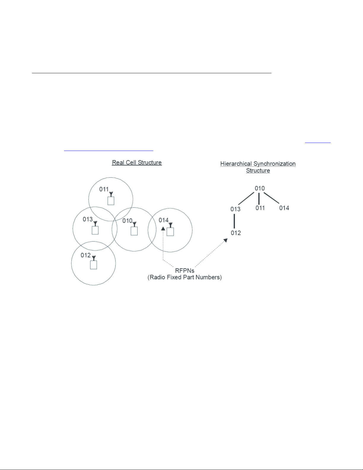
Synchronization hierarchy
If two or more DAPs belong to the same system, the DAPs automatically synchronize using a
hierarchical structure. In most cases synchronization is automatic, but if your system has a
complex DAP
The DAP controller tracks the synchronization structure and assigns each DAP a unique Radio
Part Number (RPN) after the DAP starts the first time. One or more DAPs act as a
synchronization source to form the root of the hierarchical structure, as illustrated in
DAP synchronization hierarchy on page 21.
cell structure, you must manually configure synchronization.
Components of SIP DECT systems
Figure 3:
Figure 3: DAP synchronization hierarchy
If more than one synchronization source is present, each one forms a separate hierarchy of
DAPs called a synchronization island.
Automatic synchronization occurs within each synchronization island using the following
rules.
After a DAP starts, it searches for existing DAPs. If it finds one with a lower RPN, it
•
synchronizes with it. If no other DAP exists with a lower RPN, the new DAP becomes the
synchronization source.
Important:
Extra DAPs can be required to establish a synchronization path.
• If a DAP
path to the synchronization master. If two or more DAPs have the same path length
SIP DECT Fundamentals October 2012 21
detects more than one other DAP, it synchronizes with the DAP with the shortest
Page 22

Site planning and hardware deployment
separating them from the master, the new DAP synchronizes to the DAP with the lowest
RPN.
Important:
After you install SIP DECT, wait at least 15 minutes until you see the results of the automatic
synchronization.
To make a DAP a synchronization master or to give a DAP a higher position in the
synchronization structure, you can manually assign a lower RPN number to a DAP. You can
manually assign RPNs using the DAP Manager Web interface. Automatically assigned RPNs
start at 010. If you manually assign a new RPN, ensure that it is in the range 000 to 00F.
Important:
You must determine the position of the Synchronization Master before you start site
planning. Place the synchronization master, which is the DAP with the lowest RPN, in the
middle of your site, building, or buildings.
Signal strength and frame errors
Signal strength is important for DAP-handset communication (voice quality) and
synchronization between DAPs.
synchronization.
• T o achieve a good voice quality , the minimum signal strength at the receiver in the handset
and DAP must be --72 Decibels (referenced to milliwatts) (dBm). This includes a margin
of --10 dBm for fast fading dips.
• Synchronization is possible if the strength of the received signal from another DAP is --80
dBm to --85 dBm. This is adjustable.
• In an open area, the distance is doubled if the received signal strength is 6 dB lower. This
means that at a minimum signal strength for good voice quality of --72 dBm and a distance
X, the signal strength at the double distance, 2X, is --78 dBm. For more information, see
Figure 4: Signal strength considerations on page 23.
The following items are relevant for the signal strength for
22 SIP DECT Fundamentals October 2012
Comments? infodev@avaya.com
Page 23

Figure 4: Signal strength considerations
Components of SIP DECT systems
• An open area has more than suf
level at the double distance is --78 dBm. The required level is --80 dBm to --85 dBm. This
leaves a safely margin of 2 to 7 dB.
• Obstructions between the DAPs can introduce loss. Also, many objects cause reflections
that let the signal reach the DAPs through other path with sufficient signal strength.
• In rare cases, factors in the surrounding environment can cause the error rate in the
received frames to be temporarily much higher than is normal for speech. An occasionally
elevated error rate does not indicate a problem with your SIP DECT system. However, if
you consistently see a high error rate, then there is a problem with the deployment of your
SIP DECT system.
Frame errors:
Frame errors rarely can occur in DECT. The number of frame errors for each reading may not
be more than four. The most common cause of frame errors higher than four is a high number
of reflections. This causes an audible click during calls.
IP network configuration
The IP
planning an IP network that is suitable for supporting SIP DECT.
network must be able to support SIP DECT; this section provides information about
ficient signal strength for synchronization. The expected
SIP DECT typically uses existing IP network infrastructure and facilities for the network
connection. For IP connectivity, you must configure the network to ensure that all SIP DECT
components have the following characteristics:
• are equipped with unique IP addresses (some static, some dynamic)
• can reach all the required services
• can be reached by all clients and counterparts
SIP DECT Fundamentals October 2012 23
Page 24

Site planning and hardware deployment
Ethernet requirements
The following items describe the Ethernet requirements.
• The IP
DECT Voice over IP.
• The IP network must support transparent IP multicast between all DAPs and the DAP
controller.
• Connect only one DAP to one IP Switch port.
• DAP supports full duplex and supports autonegotiation if DAP is connected to a port on
an Ethernet Switch.
• Ensure that enough unique IP addresses are available to support both data networking
traffic and SIP DECT components. Y ou can configure private IP addresses for local traffic,
and you can configure private IP addresses on the local network to connect to public IP
addresses if you use Network Address Translation (NAT). However, SIP DECT does not
support NAT.
• Ensure that IP addresses and routing are consistent with each other to deliver the required
transparency . Also ensure that IP addresses are consistent with routing for normal unicast
traffic as well as for the required multicast traffic.
network must offer a Quality of Service (QoS) that is sufficient to support the SIP
Important:
Configure the Ethernet switch ports to which the DAPs are connected to use
autonegotiation. If the switch does not support autonegotiation, you can use full-duplex;
however SIP DECT can operate incorrectly on some switches when you configure them
to use full-duplex.
• The maximum cable length between the DAP and IP network equipment, such as a
switch, is 100 meters for a Category 5, unshielded twisted-pair, half-duplex cable. If the
required cable length between the IP network equipment and the DAP exceeds 100
meters, use Long Range Ethernet equipment in the connection. Several manufacturers
offer such a solution, which allows cable lengths of more than one kilometer (km).
Fixed IP network addresses
ou must provision fixed IP addresses for the following servers:
Y
• The TFTP server stores the configuration file and the firmware that are available to the
DAPs. After a DAP starts up, the DHCP server sends the DAP the IP address of the TFTP
24 SIP DECT Fundamentals October 2012
Comments? infodev@avaya.com
Page 25

server. The DAP then downloads the configuration files from the TFTP server . The TFTP
server often runs on the DAP controller or manager PC.
• The DHCP server (optional) sends the address of the DNS server to the DAP. The DAP
does not support Domain Name Resolution.
• The DAP controller or manager requires a fixed IP address. The DAPs retrieve this fixed
IP address from the configuration file that the DAP loads from the TFTP server.
• The IP address of the PABX is reachable either through a router or directly . The PABX is
sometimes referred to as Gatekeeper or SIP proxy, depending on the type of PABX that
is used.
To facilitate network management, Avaya recommends that fixed IP addresses are also
assigned by the DHCP server . Ensure that the DHCP server has the hardware MAC addresses
of all servers to issue the proper (fixed) IP addresses to each individual server.
The DAP IP address can be stored in flash memory. If the IP address is stored, the DHCP
server is needed only for the first startup. Then an IP address is assigned to the DAP.
Dynamic IP network addresses
Components of SIP DECT systems
Network stations, which are not servers (PC workstations and DAPs), can use dynamic IP
addresses assigned by DHCP
addresses of all the network stations in the DHCP server.
Ensure that you configure the DHCP server to assign IP addresses from a specific range to
unknown MAC addresses. However, unknown LAN stations have valid IP addresses, which
can be a minor network security issue. To solve this, use the Vendor Class Identification (VCI)
in the DHCP server . The DHCP server issues IP addresses only to devices that have the DAP
VCI. Ensure that the DHCP server can make a distinction in VCIs. The DAP VCI is D(ECT)AP
49.
Each DAP in a SIP DECT system is assigned a dynamic IP addresses by the DHCP server.
You can configure the DAPs to store the IP address in flash memory, so the DHCP server is
required only during the initial configuration of the system.
Multicast addresses
DECT uses Multicast addresses for the following functions:
SIP
• Communication between the SIP DECT network components to locate or address a
handset. If a handset must be reached, the request must simultaneously go to all DAPs.
For example, if you use the page function during an incoming call, a single multicast
message is sent to all DAPs to find the DAP for your handset quickly and efficiently.
. For dynamic IP addresses, you need not specify the MAC
• Seamless handover from one DAP to the other If inter-cell handover is necessary, the
media path must be redirected from the existing DAP to another DAP. The handset always
initiates a handover. The handset sends request to another DAP (not the DAP with the
SIP DECT Fundamentals October 2012 25
Page 26

Site planning and hardware deployment
current connection). This DAP issues a multicast on the network to determine on which
DAP the voice connection exists. The DAP, with the existing voice connection, responds
and then the connection can be redirected from the DAP with the existing voice connection
to the new DAP.
• Synchronization between DAPs Y ou must configure multicast before synchronization can
occur between DAPs in the SIP DECT system.
All network components must support forwarding of IP multicast packages. The IP DECT
Configurator proposes a default multicast IP address (239.192.49.49). This is a multicast
address in the private multicast IP address range for use in private IP networks. If you are not
sure you can access this address, contact the local IT manager.
Important:
You must disable IGMP Snooping and Spanning Tree Protocol on switch ports where SIP
DECT equipment is connected. For more information, see DAP multicast group
membership on page 259.
Location requirements
Comply with the following requirements for DAP
• Ensure that the location complies with local electrical codes.
• Install DAPs indoors where no condensation occurs and the temperature remains within
the range of 0°C to 40°C. (of -20C to +40C for external housing).
• Install the C4710 and C4710E DAPs in a vertical position. The radiation pattern differs
between the horizontal and vertical positions. The 4720 and 4720E can be installed
horizontally only if you change the antenna position. For more information, see
the antenna position on page 177
Do not mount a DAP to a metal surface.
•
• Do not roll up the extra cabling behind a DAP.
• Position DAPs upright on walls. DAPs must be at least 30 cm from the ceiling.
• Position DAPs at least 1 meter (m) from large concrete or stone columns and from major
building structural members such as support beams or columns.
• Position the DAPs high enough to clear obstructions between the DAPs and the cell edge
close to the ceiling.
• Mount the DAPs clear of obstacles such as pipes or ducts.
For more information about the 4720 DAP mounting procedure, see
on a wall on page
To install the DAPs outdoors, see
180
Install the external housing on page 217
location:
Adjusting
Mounting the 4720 DAP
.
26 SIP DECT Fundamentals October 2012
Comments? infodev@avaya.com
Page 27
DAP power configuration
The C4710 and C4710E DAPs are powered using one of the following methods:
Components of SIP DECT systems
• Locally
an AC adaptor that provides at least 10 W atts. For part numbers of available AC adaptors,
see
Table 1: Part numbers
• Through Power over Ethernet (PoE), as defined by IEEE802.3af specifications. The DAPs
support both phantom power and power over spare wires. The following specifications
apply to PoE power.
Both phantom power and power over spare wires are provisioned on the same DAP to provide
system redundancy . The power input providing the highest voltage is active. If one power input
fails, the other takes over without service interruption.
The 4720 and 4720E DAPs are powered only through Power over Ethernet (PoE) with the
following specifications:
, using an RJ-1 1 connector. The AC voltage must be 40V (+ or --10 percent). Use
Table 1: Part numbers on page 27
NTCW28AAE5 N0162030 DAP AC/AC adaptor Eur
NTCW28BAE5 N0162032 DAP AC/AC adaptor UK
NTCW28CAE5 N0162033 DAP AC/AC adaptor ANZ
- Minimum 36 Volts and maximum 60 Volts of voltage at the DAP
- Standard RJ-45 connector, using the spare wires pins (wires)
- Maximum cable length of 100 meters
.
• Voltage at C4720(E) via PoE : 36 . . . . 57 V. DC
• PoE Class ............................. : Class 2
• Power Consumption ............. : 6 Watt maximum
Wire color coding for Category 5 cables
This section shows you the normal color coding for Category 5 cables (4 pair) based on the
two standards supported by
the color code used with a single cable run.
Important:
Both cable ends must use the same standard!
Which standard to use is a matter of local decision. However
pin out at the connector,s you can mix 568A and 568B cables in any installation.
SIP DECT Fundamentals October 2012 27
TIA/EIA: the 568A and 568B standard. These standards apply to
, since they both use the same
Page 28

Site planning and hardware deployment
Figure 5: Color Schemes for Wires in Category 5 Ethernet Cabling
Types of SIP DECT configuration
ou can implement SIP DECT in various system configurations to accommodate your needs.
Y
The most common SIP DECT configurations are as follows:
• Basic (or Simple) Configuration
• Routed Head Quarter Configuration
• Branch Office Configuration
• Routed Head Quarter Configuration with Branch Office
• Multi Site Mobility Network Configuration
Basic (or Simple) Configuration:
In Basic Configuration, all DAPs are in the same subnet that is based on one or more IP
switches. IP multicast must be able to occur between all DAPs. The configuration supports
28 SIP DECT Fundamentals October 2012
Comments? infodev@avaya.com
Page 29

Types of SIP DECT configuration
seamless handover between all DAPs. For an illustration of a simple SIP DECT configuration,
see Figure 6: Simple SIP DECT network configuration on page
Figure 6: Simple SIP DECT network configuration
29.
Routed Head Quarter configuration:
Routed Head Quarter Configuration is used for a Large Campus network that is split into
several subnets. In this configuration DAPs belong to various subnets and behave as one large
DECT system with the full support of seamless handover. IP multicast must be able to
SIP
occur between all DAPs in the Campus network, through IP switches and the IP routers that
connect the various subnets. For an illustration of a Routed Head Quarter configuration, see
Figure 7: SIP DECT configuration Routed Head Quarter on page 30
.
SIP DECT Fundamentals October 2012 29
Page 30

Site planning and hardware deployment
Figure 7: SIP DECT configuration Routed Head Quarter
In Routed Head Quarter Configuration, the network settings must comply with the following
requirements:
•
The network must support Quality of Service (QoS) and IP connectivity throughout the
Campus.
• Routers must support IP multicast routing.
• The IP multicast address for SIP DECT must be the same in all subnets.
• Multicast Time to live (TTL) must be greater than 1.
• In the SIP DECT configuration, you must use an “aggregated” subnet mask that covers
all the subnets where DAPs are present. For instance, if each subnet is defined by mask
255.255.255.0, then “aggregated” mask 255.255.248.0 covers up to four such subnets.
Branch Office Configuration:
Branch Office Configuration is used for a Large Campus network that is split into various
(geographical) segments (branch offices). IP multicast must be able to occur between all DAPs
in every branch office and no IP multicast is allowed between any two branch offices. In this
configuration, each branch office behaves as an isolated site of a large SIP DECT system.
Branch Office configuration supports seamless handover within each isolated site (branch
office), but not between sites. Support is unavailable for roaming between branch offices. For
30 SIP DECT Fundamentals October 2012
Comments? infodev@avaya.com
Page 31

Types of SIP DECT configuration
an illustration of a Branch Office Configuration, see Figure 8: Branch Office Configuration on
page 31.
Figure 8: Branch Office Configuration
For Branch Of
fice Configuration, network settings must comply with the following requirements:
• The network between Branch Offices and Call Server must support QoS.
• Branch Offices must be in separate subnets (IP router(s) needed).
• DAPs in various Branch Offices must be located so that no synchronization can occur
between any two DAPs belonging to various Branch Offices.
• Routers must block IP multicast between Branch Offices (multicast TTL = 1, which means
that IP multicast packets do not cross IP routers).
Routed Head Quarter Configuration with Branch Office:
Routed Head Quarter Configuration with Branch Office makes it possible to create a Routed
Head Quarter Configuration in one (and only one) the branch office. Within the Branch Office
with Routed Head Quarter, DAPs belong to various subnets and behave as a single site of one
SIP DECT system with the full support of seamless handover. As for the whole SIP DECT
system, each Branch Office (including the Branch Office with Routed Head Quarter) behaves
as isolated site of that SIP DECT system. Branch Office configuration supports seamless
handover within each isolated site (branch office), but not between sites. Support is unavailable
for roaming between branch offices.
SIP DECT Fundamentals October 2012 31
Page 32

Site planning and hardware deployment
Figure 9: Routed Head Quarter Configuration with Branch Office
In Routed Head Quarter Configuration with Branch Of
fice the network settings must comply
with the requirements for Routed Head Quarter configuration (for the network settings within
Routed Head Quarter) and with the requirements for Branch Office configurations (for the
network settings between Branch Offices, including the Branch Office with Routed Head
Quarter).
Multi Site Mobility Network Configuration:
Multi Site Mobility Network (MSMN) Configuration makes it possible to use portable DECT
handsets on various MCDN nodes where each node is a CS 1000 system plus the
corresponding SIP DECT system. MSMN allows roaming between independent SIP DECT
systems installed on separate Call Servers (connected by trunks). Handover between
independent SIP DECT systems is not possible.
A SIP DECT system on an individual MCDN node can be any of the previously described
configurations: Basic (Simple), Routed Head Quarter, Branch Of fice, or Routed Head Quarter
with Branch Office.
MSMN requires unrestricted MSMN package 370 and a number of free wireless visitors
licenses, which are regulated by ISM mechanism. If there are only restricted MSMN packages
or if there are no wireless visitors licenses the following occurs:
• A new UEXT SIPL visitor client cannot be created (the VSIT and HMDN prompts are not
shown).
• A non-visitor UEXT cannot be changed to UEXT SIPL visitor (the VSIT and HMDN
prompts are not shown).
32 SIP DECT Fundamentals October 2012
Comments? infodev@avaya.com
Page 33

• All visitor UEXT SIPL clients above the maximum licenses number are deleted on
sysload.
• All visitor UEXT SIPL clients are deleted on sysload if the MSMN package is restricted.
• Overlay 20 does not print the VSIT and HMDN lines in reports.
• − The visitor UEXT SIPL client cannot move to the new location where the package and
license limits exist (Set Relocation feature).
Site planning
Site planning is an information gathering process that begins with a site survey and ends with
deploying SIP
requirements and the number of cells required to support traffic.
You can use the Location builder tool (a part of the DAP controller software package) to plan
your site. For more information, see
Site planning
DECT. The information received in the site survey determines customer
Location builder tool on page
183.
Site survey
•
• Number of users (handsets)
• Allowed and prohibited DAP positions
• Details of required coverage
• Position of the DECT System and available cabling
Site maps
Site maps are an essential requirement in advance of a survey. A map of the complete
site (if more than one building) and plans of each floor of each building are required. Make
sure that dimensions are clearly stated on the maps. Additional information such as the
use of buildings (office, hotel, factory, store), construction materials (walls, floors,
ceilings), and cabling infrastructure are helpful in estimating DAP positions in advance.
Number of users (handsets), both initial and foreseeable growth, and areas of above
average and below average traffic density.
A customer can prohibit the installation of DAPs in certain areas, or require that DAPs be
installed out of sight.
Determine to what areas coverage must extend; for example: elevators, stairwells, toilets,
outdoor areas.
Ensure that you can use existing cabling for the connection between the DECT System,
and that the DAP cables meet or exceed the UTP Cat 5 standard. If the type and quality
of the available cabling is not sufficient for the connection and limits the maximum distance
between the DAP and DECT System, you may require new cabling.
SIP DECT Fundamentals October 2012 33
Page 34

Site planning and hardware deployment
• Sensitive electronic equipment
Check whether sensitive electronic equipment is present, for example, laboratory or
medical equipment.
it can interfere with some sensitive electronic equipment.
• Traffic information
Gather information about user density, amount of traffic, and whether redundancy is
required. You require this information to determine the number of DAPs that are required
and therefore the required cabling.
A DAP must always have at least one channel free to allow handover (either intracell or
intercell handover). Make sure that the maximum expected traffic density is not more than
11 channels simultaneously.
Although the transmitted power of the DAPs is low (about 250 mW),
For more information, see
Speech quality
A
relationship always exists between coverage and speech quality. The greater the distance
between the handset and the DAP, the lower the quality. Therefore, you must understand the
relationship between the coverage and the expected voice quality. For an illustration of the
relationship between coverage and voice quality in an open environment, see
Coverage and speech quality in an open environment. on page 35.
Site survey example on page 199.
Figure 10:
34 SIP DECT Fundamentals October 2012
Comments? infodev@avaya.com
Page 35

Figure 10: Coverage and speech quality in an open environment.
Site planning
Be aware that DECT
is a digital communication system. It incorporates a “transmission errors
hiding” system. This means that it tries to hide the transmission errors. The results of this
mechanism are as follows:
• A small incidental transmission error is not noticeable in speech.
• A minor transmission error causes audible clicks during speech.
• A major transmission error causes the loss of speech.
The following factors effects the voice quality as well:
• Moving speed
The DECT techniques allow a maximum moving speed of 5 kilometers per hour (km/h).
Bear this in mind if your DECT system must cover an elevator.
• Metal Construction
In metal structures, reflection can negatively impact voice quality (clicks and interruptions
can occur) even if you are close to the DAP. This effect is made worse when the handset
is in motion.
For more information see
Coverage calculation on page 36.
The required quality depends on the customer requirements and the environment. The
following are the various quality levels:
• Excellent and good
In business, office, and first aid environments, the excellent and good voice quality is
required to avoid dropped calls, inherent sounds, or pauses in important conversations.
SIP DECT Fundamentals October 2012 35
Page 36

Site planning and hardware deployment
Any sounds produced by a lower quality level noticed by the system users, because these
environments are usually quiet or produce less background noise.
• Satisfactory
In less critical areas like basements, stock rooms, and cold stores, the satisfactory quality
level is usually accepted because they are noisy environments. In a noisy environment
people do not notice an audible click in a conversation, because the environment
produces a lot of background noise. This environmental background noise may also
contain audible clicks. Sometimes, the voice of a user is less audible to the other user
listening at the other end of the conversation because of the background noise.
Use the following points as general guidelines:
• A maximum of 20 percent of the whole coverage is considered as satisfactory.
• Install a hard-wired emergency telephone in those areas where the quality is satisfactory .
This ensures that people can always make a call in case of an emergency.
• If you agree with the customer on lower speech quality, then make sure that this is well
documented and signed by the customer. If the customer becomes dissatisfied
afterwards, you can refer to the agreement. Also, be aware that, if the speech quality is
low in certain areas, the customer may perceive that you delivered a low-quality
system.
• If a lower voice quality level is acceptable, ensure that all calls are received and dropped
calls are avoided.
Coverage calculation
The coverage can be calculated in advance before executing a site survey
on the following theory.
The transmission path between the DAP and the handset is subject to radio-propagation
related peculiarities, such as:
• Dynamically changing environment
• Signal attenuation due to fixed and moving objects
• Multi-path propagation of the signal
The signal from the transmitter is attenuated in the link before it arrives at the receiver. The
link consists of a transmission path through the air and through obstacles such as walls. The
air and the obstacles cause attenuation called insertion loss. The following table shows typical
insertion losses for some obstacles.
Table 2: Typical insertion losses of some obstacles
. Calculation is based
Material Insertion loss (dB)
Glass 2
36 SIP DECT Fundamentals October 2012
Comments? infodev@avaya.com
Page 37

Site planning
Material Insertion loss (dB)
Glass, metal reinforced grid 10
Glass, metal clad sunguard 10
Wall, indoor, plaster, wood 2
Wall, brick, 10 cm 3.5
Wall concrete, 10 cm 6
Wall concrete, 15 cm 9
Wall concrete, 20 cm, large windows 6
Wall concrete, 40 cm 17
Ceiling, concrete, reinforced, tiles 17-20
With the DECT equipment, the available link budget is 38 dB. This is the maximum allowed
loss in the link, under constraints of excellent and good speech quality and the ability for the
user to move.
To calculate the distance between DAP and handset, use the information in Figure 11: DECT
range calculation chart on page 38.
Using the building map, start at the possible DAP location. Move away from the DAP location.
Calculate the distance. When you encounter an obstacle, calculate the insertion loss. Using
the chart below, start in the lower left corner (0,0), move horizontally, to the value for the actual
distance. Move vertically to the value for the insertion loss of the encountered obstacle. If the
curve in the chart is crossed, read the maximum distance for that specific DAP in that situation.
This gives the cell size in that specific direction. Ensure that outside the calculated range
communication is possible but a good voice quality is no longer guaranteed.
SIP DECT Fundamentals October 2012 37
Page 38

Site planning and hardware deployment
Figure 11: DECT range calculation chart
The range in the air is 80 m from the DAP
, for optimal communication quality . The result of this
coverage calculation is a map with possible DAP positions indicated.
Use the following DAP ranges as a rough guide for planning the DAP positions:
• In the line of sights the DAP has a range of approximately 80 m.
• In halls the DAP has a range less than 80 m.
• In buildings the DAP has a range of 15 to 40 m. This is based on the assumption that
walls are made of light brick, plasterboard or wallboard with metal frames. Normal
electrical wiring, central heating pipes, office furniture and desktop computer equipment
have no significant effect. Ensure that you consider the signal shadowing effect of
stairways, lift shafts, and shielded rooms.
The following items cause shadowing of the radio signal:
• Thick walls, especially cavity walls and reinforced concrete walls.
• Windows or glass in doors with steel wire reinforcement or metallic reflection film.
• Steel doors, partitions, or walls.
38 SIP DECT Fundamentals October 2012
Comments? infodev@avaya.com
Page 39

Site planning
• Fire resistant doors.
• A wall of steel cabinets, large computer equipment or machinery.
• Thick concrete floors.
During the site survey, be aware of the following:
• Choose a corridor or other large open space, rather than an enclosed area, so that the
radio signal passes through as few walls as possible to reach as large an area as
possible.
• Radio reception inside a vehicle is poor unless the user is close to the DAP.
• Ensure that the DAP is placed high enough to be unaffected by surrounding objects. For
example, a DAP in a car park needs to be placed higher than a vehicle that is parked next
to it.
• Ensure that DAPs are separated by at least 1 meter.
• The presence of another unsynchronised DECT System, or any similar system in adjacent
buildings, causes interference.
• A DAP or a DECT Handset interferes with sensitive laboratory equipment and medical
equipment (for example, ensure that DAPs are installed outside of an operating room at
an hospital.)
• Ensure that significant interference from unsuppressed engines or electric motors is
accounted for.
Traffic density calculations
Perform the traf
system.
For traffic calculations, you must know
• the number of users
• the type of users
The following table lists the three user types.
Table 3: Three user types
Traffic Application Erlang/User
Average Executive and secretary groups 0.1-0.15
fic density calculations so that you have a low blocking probability in the
Low normal offices 0.05
High help desks, Tele-services 0.2-0.25
SIP DECT Fundamentals October 2012 39
Page 40

Site planning and hardware deployment
The Erlang value for DAP C4710(E) and C4720(E) (12 radio channels), with blocking
probability of 0.5%, is 5.25.
Calculate the traffic density using the following formula:
One cell has 20 users: five average traffic and 15 low traffic. The load is: (5 x 0.15) + (15 x
0.05) = 1.5 Erlang
Therefore, one 12 channel DAP
System deployment
This section describes the basics of SIP DECT system deployment.
DECT Deployment Kit 2
The DECT
The DECT Deployment Kit 2 is shown in
page 41. For more information about the deployment kit, see the DeT
accompanies each kit.
Important:
If you use an older deployment tool that dif
Deployment tool on page 205
Deployment Tool (deployment tool) determines cell centers and cell boundaries.
is sufficient for this cell.
Figure 12: Deployment Kit 2 and carrying case on
eWe User Manual that
fers from the one in the following figure , see
.
40 SIP DECT Fundamentals October 2012
Comments? infodev@avaya.com
Page 41

System deployment
Figure 12: Deployment Kit 2 and carrying case
The following figures shows the assembled kit.
SIP DECT Fundamentals October 2012 41
Page 42

Site planning and hardware deployment
Figure 13: Assembled Deployment Kit 2 and DeTeWe handsets
42 SIP DECT Fundamentals October 2012
Comments? infodev@avaya.com
Page 43

System deployment
Figure 14: Deployment Kit 2 basestation
Use the following information in conjunction with the DeT
eWe User Manual that accompanies
the deployment tool.
• The two DeTeWe handsets with the kit are subscribed to the basestation and are
numbered 13 and 15. To view the assembled basestation and the DeT eWe handsets, see
Figure 13: Assembled Deployment Kit 2 and DeTeWe handsets on page 42
.
• The key on the handset is the Off-Hook key.
Accessing site survey mode
o access the Site Survey Mode on the DECT Handset, perform the following procedure.
T
.
1. Press Menu.
2. Scroll down to System.
3. Dial ***76#.
4. Scroll down to Site Survey.
5. Press OK.
6. Use the handset to detect frame errors and signal strength.
The Frame Error value for the handset is the number of detected Sync/ACRC errors
within the last 100 receiving frames; for example, 1 second. For proper deployment,
ensure the Frame Error value does not exceed 4. An Radio Signal Strength
SIP DECT Fundamentals October 2012 43
Page 44

Site planning and hardware deployment
Indication (RSSI) value of –80 dBm to –85 dBm is used to indicate the cell boundary .
For more information, see Signal strength and frame errors on page
Re-subscribing a handset
To re-subscribe a handset that has de-subscribed in error, perform the following procedure.
1. Long-press the button on the basestation to open the DECT system.
2. On the handset, navigate to Menu > System > Subscription > New.
3. Enter the PARK number provided at the bottom of the basestation.
4. Enter the authorization code (the last four digits of the serial number at the bottom
of the basestation).
Deployment terms
The following table lists terms associated with deployment.
T
able 4: Deployment terms
22.
Term Definition
Estimated number of handsets The average number of handsets expected
in a particular cell.
Cell The coverage area provided by a
basestation.
Cell boundary The edge of a cell showing the cell coverage
area.
Cell center The place where all the basestations are
installed.
DECT Radio Deployment Tool The tool used to determine the radio range
of a basestation.
Critical point A point or location defined as an outer corner
of a coverage area, or points that can be
ficult for the radio signal to reach.
dif
Coverage area The area defined by the customer in which a
handset user can expect to be able to make
and receive calls.
Link If a handset and a basestation are in radio
communication with each other.
Range The distance from a cell center to the cell
boundary.
Office The location where a handset user spends
the majority of the day.
44 SIP DECT Fundamentals October 2012
Comments? infodev@avaya.com
Page 45

System deployment
Term Definition
Traffic table Traffic tables record site traffic information
from the floor plan and the customer
traffic table helps to determine the required
number of basestations for each cell.
. The
The following figure illustrates some of the preceding terms.
Figure 15: Example showing deployment terms
Deploying on a single floor
Use the information in this section when you are installing SIP
Use the following procedure to identify critical points when installing on a single floor.
Identifying critical points on the floor
Mark critical points.
DECT on a single floor.
SIP DECT Fundamentals October 2012 45
Page 46

Site planning and hardware deployment
A critical point is a place that can be difficult for the radio signal to reach, such as a
corner of a room, lifts, and stairwells. Initial critical points are shown in Figure 16:
Example of initial critical points on page 46 as: P1, P2, P3, P5, P6 and P7.
Figure 16: Example of initial critical points
A
specific RSSI value on the handset defines the cell boundary range. Links can be made
outside the cell boundary but the audio quality of the link is poor. The link drops if the handset
and the basestation are too far apart.
As shown in
Figure 17: Cell boundary terminology on page
47, the cell boundary is the
farthest point from the cell center where a clear radio signal can be heard.
Determine the range from the cell center to the cell boundary , or the distance to a potential cell
center from a critical point, by using the cell boundary value and the deployment tool.
Important:
Close all doors, and hold the survey handset about 1.2 m above the ground.
46 SIP DECT Fundamentals October 2012
Comments? infodev@avaya.com
Page 47

Figure 17: Cell boundary terminology
System deployment
Determine a cell boundary for the cell center by placing the deployment tool at the cell center
and using the deployment handset to establish the cell boundary.
Use the following procedure to mark the cell contour based on the most distant point.
Demarcating the cell contour for the critical point farthest from the center of the
full coverage area
1. Set up the deployment tool basestation. Raise the deployment tool basestation as
high as possible, or until it is at the height recommended for basestations.
2. Enter the site survey mode on the handset.
For more information, see Entering the site survey mode on page
Deployment Kit 2, or
Entering the monitor mode on page
213 if you use an older
Deployment tool.
3. Measure the range into the coverage area in a few directions to determine where a
cell center can be located and still be within range of the critical point.
Listen to the deployment tool handset while moving away from the basestation. After
the RSSI value changes from 7 to 6 (--80dBm to --85dBm), the cell boundary is
detected.
For more information about deployment requirements, see
Radio
synchronization on page 19.
Mark the cell boundary on the floor plan with a small x.
4.
43 if you use
5. Repeat step 3 and step 4 until you have sufficient Xs to draw a thin contour arc
through the Xs.
SIP DECT Fundamentals October 2012 47
Page 48

Site planning and hardware deployment
In Figure 18: Cell contour of the initial critical point on page
critical point.
Figure 18: Cell contour of the initial critical point
48, P1 is the initial
Demarcating the cell contour of the closest adjacent critical point to the first
critical point.
Repeat the described steps in Demarcating the cell contour for the critical point farthest
from the center of the full coverage area on page 47 to mark the cell contour of the
closest adjacent critical point to the first critical point.
48 SIP DECT Fundamentals October 2012
Comments? infodev@avaya.com
Page 49

System deployment
In Figure 19: Cell contour of the closest adjacent critical point to the initial critical
point on page 49, P2 is the closest adjacent critical point to the first critical point.
Figure 19: Cell contour of the closest adjacent critical point to the initial critical point
Use the following procedure to locate the cell center
.
Locating the cell center
1. Place the deployment tool at one critical point and then use the deployment handset
to obtain a change in audio quality. The audio quality change determines the cell
boundary contour.
2. Repeat step 1 at an adjacent critical point. The call center is where the cell
boundaries of both critical points meet. Mark the cell center position on a floor
plan.
3. Use the cell contours to locate a cell center.
Locate the cell center where the cell contours meet. Choose a position on the floor
plan that meets the following requirements:
• is farthest from the critical points
• provides good audio quality at the critical point,
• complies with the requirements described in section
requirements on page
19
• is in the coverage area
Label the cell center on the floor plan with the following symbol. xCn, where x = the
floor and n = is the cell number in sequence of the entire plan.
Deployment
SIP DECT Fundamentals October 2012 49
Page 50

Site planning and hardware deployment
In Figure 20: Example of a cell center on page
Figure 20: Example of a cell center
50, IC1 is a cell center.
Use the following procedure to mark the cell boundary
Demarcating a cell boundary
1. Set up the deployment tool basestation at the cell center.
2. Enter the site survey mode on the handset.
For more information, see
Deployment Kit 2, or
Deployment tool.
3. See the floor plan and check audio quality in user offices within the cell. If a user
office is in a zone where audio quality deteriorates, relocate the cell center closer
to the critical point or the office.
4. Walk into all the areas (rooms) necessary to mark the complete cell boundary . Radio
signals travel further in uncluttered areas than in cluttered areas. Record the cell
boundary.
5. Find the cell boundary by measuring the range and marking it on the floor plan with
a small x. Repeat steps
Xs so you can draw a contour arc around the cell center.
For an example of a cell boundary, see Figure 21: Example of a cell center
boundary on page
51.
Entering the site survey mode on page
Entering the monitor mode on page
3 on page 50 and 4 on page 50 until there you have sufficient
.
43 if you use
213 if you use an older
50 SIP DECT Fundamentals October 2012
Comments? infodev@avaya.com
Page 51

Figure 21: Example of a cell center boundary
System deployment
Use the following procedure to mark and label the cell boundary
.
Marking and labeling the cell boundary on the floor plan
1. Mark each office within the cell that is isolated from the office area.
2. Label subsequent critical points on the floor plan with the following symbol.
3. Mark the cell contour on the floor plan by tracing a contour line through the Xs with
a marker
.
4. Trace the cell boundaries and cell centers with colored markers.
Use the following procedure to identify new critical points.
Identifying new critical points
1. Identify one new critical point slightly inside of where the cell boundary meets the
outside wall.
Figure 22: Example of new critical points (P8 and P9) on page 52, this new
In
critical point is P9.
2. Identify another new critical point which is adjacent to the first new critical point.
Locate this critical point on the opposite side of the cell boundary area.
In Figure 22: Example of new critical points (P8 and P9) on page 52, the cell
boundary area is IC1 and the new critical point is P8.
SIP DECT Fundamentals October 2012 51
Page 52

Site planning and hardware deployment
Figure 22: Example of new critical points (P8 and P9)
Use the following procedure to mark and label new critical points.
Marking and labeling new critical points
Mark and label these new critical points on the floor plan with the following symbol.
For more information, see Marking and labeling the cell boundary on the floor plan on
page 51.
Use the following procedure to mark new cell contours and a new cell boundary
.
Demarcating new cell contours, a new center and a new cell boundary
Using the critical points from
Identifying new critical points on page
contours, a new cell center and a new cell boundary.
For more information, see
from the center of the full coverage area on page
boundary on page
50.
Demarcating the cell contour for the critical point farthest
47 to
Demarcating a cell
51, mark new cell
52 SIP DECT Fundamentals October 2012
Comments? infodev@avaya.com
Page 53

System deployment
Cell contour arcs must pass near the cell boundary of adjacent cells. For an example,
see Figure 23: Example of deployment for cell center 1C2 on page 53
.
Figure 23: Example of deployment for cell center 1C2
Use the following procedure to mark cell contours, centers, and boundaries at the far end of
the intended coverage area.
Demarcating additional cell contours, centers and boundaries at the far end of
the building
Repeat the procedures Identifying critical points on the floor on page 45 toMarking and
labeling new critical points on page 52
as necessary to mark new cell boundaries at
SIP DECT Fundamentals October 2012 53
Page 54

Site planning and hardware deployment
the other end of the building. In Figure 24: Example of deployment for cells 1C3 and
1C4 on page 54
, new cells are formed around cell centers IC3 and IC4.
Figure 24: Example of deployment for cells 1C3 and 1C4
Use the following procedure to identify new critical points.
Identifying new critical points
1.
Mark critical points adjacent to a critical point and on the opposite side of the cell
boundary area. (critical point = P11 in
P12, P13, P14, P15, P16, P17) on page 55
The critical points must be as follows.
2. Mark critical points inside of where the cell boundary meets the outside wall (P12,
P13, P14, and P15 in
P15, P16, P17) on page 55
Figure 25: Identify new critical points (P11, P12, P13, P14,
, and
3. Mark critical points where cell boundaries meet (P16 and P17 in
new critical points (P11, P12, P13, P14, P15, P16, P17) on page
Figure 25: Identify new critical points (P11,
, where cell boundary area = IC2),
Figure 25: Identify
55.
54 SIP DECT Fundamentals October 2012
Comments? infodev@avaya.com
Page 55

Figure 25: Identify new critical points (P11, P12, P13, P14, P15, P16, P17)
System deployment
Use the following procedure to mark additional cell boundaries and define the extent of the
coverage area.
Demarcate additional cell boundaries to cover all areas of the building
Repeat the procedures Identifying critical points on the floor on page
and labeling new critical points on page 52
as necessary to mark new cell boundaries
at the middle of the building.
Critical points P11, P13 and P16 form the following:
• contours in
page
• the cell center 1C5 in
Figure 26: Contours formed by critical points P11, P13, and P16 on
56
Figure 27: Cell center 1C5 formed by critical points P11,
P13, and P16 on page 56
• a new cell boundary in Figure 28: Cell boundary 1C5 formed by critical points P1 1,
P13, and P16 on page 57
Critical points P1
• contours in
•
a new boundary based on cell center 1C6 in
1, P12, and P17 form the following:
Figure 29: Example of critical point cell boundaries on page 57
Figure 30: Example of cell center
boundary 1C6 on page 58
45 to
Marking
SIP DECT Fundamentals October 2012 55
Page 56

Site planning and hardware deployment
Figure 26: Contours formed by critical points P11, P13, and P16 on page 56
shows
a floor plan with complete radio coverage. Cell boundary 1C7 completes the floor
plan.
Figure 26: Contours formed by critical points P11, P13, and P16
Figure 27: Cell center 1C5 formed by critical points P11, P13, and P16
56 SIP DECT Fundamentals October 2012
Comments? infodev@avaya.com
Page 57

Figure 28: Cell boundary 1C5 formed by critical points P11, P13, and P16
System deployment
Figure 29: Example of critical point cell boundaries
SIP DECT Fundamentals October 2012 57
Page 58

Site planning and hardware deployment
Figure 30: Example of cell center boundary 1C6
Deploying on multiple floors
Use the information in this section to deploy SIP DECT in the following situations.
• The coverage area is on more than one floor.
• The floors are not adjacent.
Checking for through-the-floor coverage
The first step in covering a multi-floor building is to assess the availability of through-the-floor
coverage. In buildings mainly constructed of wood, you can use through-the-floor coverage.
However
content, and reinforced concrete, through-the-floor coverage with DECT is limited.
Checking for through-the-floor coverage
, due to the construction of most modern buildings with raised floors, high metal
1. Place the deployment tool in a middle floor of the site.
2. Go to the floor above the deployment tool and enter the site survey mode on the
handset.
For more information, see
Deployment Kit 2, or
Deployment tool.
Entering the site survey mode on page 43
Entering the monitor mode on page 213
if you use
if you use an older
58 SIP DECT Fundamentals October 2012
Comments? infodev@avaya.com
Page 59

3. Measure the deployment contour as if the basestation was on this floor, instead of
the floor below
If only a small area is covered (less than a 10 metre radius), no through-the-floor
coverage is available on the floor above an installed basestation.
4. Go to the floor below the deployment tool and repeat the preceding process.
If only a small area is covered (less than a 10 metre radius), no through-the-floor
coverage is available on the floor below an installed basestation.
5. If there is no through-the-floor coverage or coverage is restricted to a small area,
deploy each floor using critical points, or if the floors have similar floor plans, you
can use the same deployment plan on each floor.
Assess floor layout
System deployment
.
The deployment procedure changes according to the similarities and dif
floors.
• All floors have the same layout.
To begin a multi-floor deployment if all floors have the same layout, deploy one floor and
enter the data on the floor plan. Use the data from the deployed floor for other identical
floors.
For example, if the second floor of an office tower is laid out with cubicle style offices with a
perimeter of enclosed offices, and the third floor is laid out in the same manner, both floors
can have the same installation profile for basestations.
• All floors do not have the same layout.
If the floor plan varies from floor to floor, use the critical point method to deploy each distinct
floor. For more information, see
Do not underestimate the importance of changes in floor layout. Simple changes in a room
from a meeting room to a storage room can have significant impact on the coverage from a
basestation.
Prepare the tool for deployment on page 207
Multi floor coverage situations
The following situations require multi-floor coverage.
ferences of the
.
• Atriums on page 59
• High rise buildings on page 60
• Unusual conditions on page
60
Atriums
Cells in an atrium, as shown in
cells of the remainder of the building. Use the information in this section as a guide help you
SIP DECT Fundamentals October 2012 59
Figure 31: An atrium on page 60
, are usually larger than the
Page 60

Site planning and hardware deployment
to plan an atrium. No precise steps to follow when you deploy an atrium, but you must consider
several points. For more information, see Unusual conditions on page
Figure 31: An atrium
Consider the following points to deploy in an atrium:
Plan atriums to the full height.
•
60.
• Plan an atrium as one full size room, not floor by floor.
• Place cell centers within an atrium only if you intend for them to cover the atrium.
• Do not place cell centers in an atrium if you intend for them to serve adjacent areas.
• To serve adjacent areas, place the cell centers into these areas.
• Deploy the atrium first if the atrium is more than one-third the size of the building, or more
than one cell in size.
• If cell centers in adjacent dense areas serve one floor of an atrium, verify the coverage
of the cell on all of the floors that meet with the atrium.
High rise buildings
Deploy a high rise building as an unusual type of multi-floor deployment.
Test through-the-floor coverage first. If there is no through-the-floor coverage, deploy each
floor. Repeat the deployment for all floors with the same layout. In all other cases deploy floor
by floor. You must deploy a floor with many meeting rooms deploys differently from how you
deploy an area with cubicles.
Unusual conditions
No precise steps exist to follow when you deploy in unusual condition, but you must consider
several points.
To plan an unusual condition, consider the following situations.
•
Cell centers are too close on page
•
Cell centers are too far apart on page 61
Too many cell centers on page 61
•
60 SIP DECT Fundamentals October 2012
Comments? infodev@avaya.com
61
Page 61

System deployment
Cell centers are too close
If you deploy cell centers less than 10 metres apart, the handsets can initiate unnecessary
handover. Unnecessary handover results in excessive internal messaging and degraded
speech quality.
Cell centers are too far apart
If you deploy cell centers too far apart, the edge of a cell does not overlap the coverage from
another cell.
Cell centers must be within the edge of other cell centers to provide satisfactory overlap.
Overlap can be difficult to achieve where coverage is received from the floor above or the floor
below. Internal structures can cause overlap deficiencies.
Place cell centers within the cell boundary, as indicated by the deployment tool.
The installation of basestations in places other than the location shown on the plan can cause
coverage problems; for example, if the basestation is mounted on the opposite side of a wall
from its planned location.
Consider the following for basestation locations.
• Choose locations where you can easily mount basestations.
• Install basestations as close as possible to planned locations.
• Follow safety codes, and be aware aesthetics.
• Allow sufficient access to install basestations.
• Provide clear installation instructions.
• Test the coverage during post-deployment checks.
Too many cell centers
The primary concern with deploying too many cell centers is cost. T o deploy the correct number
of cell centers and minimize cost, perform the following steps:
• Verify the coverage and traffic volume before you add additional cells.
• Remove a cell served by other cells unless it is required for high handset density.
• Verify the coverage area of each cell.
• Verify that at least one area that each cell serves is not served by another cell.
In the example in Figure 32: Locating redundant cells on page 62, cell 1C3 is redundant
unless required for high handset density
.
SIP DECT Fundamentals October 2012 61
Page 62

Site planning and hardware deployment
Figure 32: Locating redundant cells
Reengineer cells for high traffic areas
o accommodate the demand in high traffic areas, follow
T
page 62
.
Traffic volume
The deployment process ensures coverage throughout the service area. It does not, however
take into account the effect of traffic. To support the volume of telephone calls in cells that carry
high traffic, you must increase the number of cells deployed.
The calculation of expected telephone traffic includes an allowance for the user population in
a cell and for the roaming user.
The cell reengineering process
The following sections describe the reengineering process.
Estimating traffic within a cell on page 63
•
• Separating the coverage area and recording the number of offices on page
Creating an estimate table on page 64
•
The cell reengineering process on
,
63
• Calculating the number of users inside the cell with an office on page 64
• Calculating the number of users with an office outside the cell who walk into the cell on
page
65
Calculating the number of users without an office on page
•
Totalling the estimate for users in a cell on page 66
•
62 SIP DECT Fundamentals October 2012
Comments? infodev@avaya.com
66
Page 63

System deployment
• Calculating the data for all remaining cells on page 67
• Creating a table to document telephone types in a cell on page 67
• Determining cell reengineering on page 68
Estimating traffic within a cell
To adjust the number of users supported by the system, you can modify the deployment
procedures you followed in Deploying on a single floor on page 45 or Deploying on multiple
floors on page 58. Perform the following three steps to estimate traffic within a cell:
• Determine the number of handset users with an office within each cell.
• Determine how many users have wired phones.
• Determine how many users without an office are normally in each cell.
Some users have both wired and handset phones; other users rely on handsets only.
Re-engineered cells for high traffic areas are represented by an adjusted estimate for the two
groups: handset and wireless, and handset only. Use the adjusted estimate to determine
whether the cell sizes can handle the telephone traffic.
If the traffic-handling capacity of the cells is not adequate, use 12-channel basestations and
subdivide them into smaller cells to ensure the traffic is handled properly according to the
instructions.
Separating the coverage area and recording the number of offices
Figure 33: Example of dividing the coverage area and recording offices
Separating the coverage area and record the number of offices
1.
Divide the floor plan into cell areas.
SIP DECT Fundamentals October 2012 63
Page 64

Site planning and hardware deployment
Mark the cell areas on the floor plan, one area for each cell, and split cell overlap
areas in half, as shown in Figure 33: Example of dividing the coverage area and
recording offices on page 63 as heavy dotted lines.
2. Count the number of user offices in each cell area.
3. Record the number of user offices on the floor plan in each cell area.
Creating an estimate table
Use the following table to estimate the number of handset users for each cell.
Table 5: Estimate users in a cell
Estimate for: 1C1 1C2 1C3 1Cn
Users inside the cell with
fice
an of
Users with an office
outside of a cell who walk
into the cell
Users without an office
Users in a cell
Creating an estimate table
1. Make an estimate table.
Include a column for each cell center.
2. Label the rows as shown in Table 5: Estimate users in a cell on page 64
3. Label each column heading with the cell center indicator.
Use this table to determine how many times to subdivide each cell to carry the
handset telephone traffic.
Calculating the number of users inside the cell with an office
Table 6: Example of the table first row calculation
Estimate for: 1C1 1C2 1C3 1C4 1C5 1C6 1C7
Users inside the cell with
fice
an of
Users with an office
outside of a cell who walk
into the cell
8.4
.
Users without an office
Users in a cell
64 SIP DECT Fundamentals October 2012
Comments? infodev@avaya.com
Page 65

System deployment
Calculating the number of users inside the cell with an office
1. Estimate the number of users in the first cell with an office.
Use the formula: (users with an office in the cell × 0.7)
2. Enter the result in the row Users inside the cell with an office.
In the example in Figure 33: Example of dividing the coverage area and recording
offices on page 63, 12 users in cell 1C1 spend 70 percent of their time in their of
fices
(12 × 0.7 = 8.4) .
Traffic engineering demonstrates that handset users with an office spend 70 percent of their
time within their home cell.
Calculating the number of users with an office outside the cell who walk into the
cell
Table 7: Example of the table second row calculation
Estimate for: 1C1 1C2 1C3 1C4 1C5 1C6 1C7
Users inside the cell with
fice
an of
Users with an office
outside of a cell who
walk into the cell
Users without an office
Users in a cell
8.4
3.2
Calculating the number of users with an office outside the cell who walk into the
cell
1.
Estimate the number of users in the first cell with an office outside of the cell who
walk into the cell.
2. Use the following formula:
3. Enter the result in the row Users with an office outside the cell who walk into the
cell.
The example in Figure 33: Example of dividing the coverage area and recording
offices on page
1C1. Therefore, 63 users can walk into cell 1C1. However, the 63 walk-in users
spend only 30 percent of their time outside their offices. Seven cells exist on the
floor plan minus cell 1C1. Accordingly, an estimate of 3.2 walk-in users can be in
cell 1C1.
63, shows 75 telephone users, minus the 12 users already in cell
SIP DECT Fundamentals October 2012 65
Page 66

Site planning and hardware deployment
Calculating the number of users without an office
Table 8: Example of the table third row calculation
Estimate for: 1C1 1C2 1C3 1C4 1C5 1C6 1C7
Users inside the cell with
fice
an of
Users with an office
outside of a cell who walk
into the cell
Users without an office 0
Users in a cell
8.4
3.2
Calculating the number of users without an office
1. Calculate the estimate for users in the first cell without an office.
Use the following formula:
2. Enter the result in the row Users without an office.
In the example shown in Figure 33: Example of dividing the coverage area and
recording offices on page
63, no users are without an office.
Totalling the estimate for users in a cell
Table 9: Example of the table first column total
Estimate for: 1C1 1C2 1C3 1C4 1C5 1C6 1C7
Users inside the cell with
fice
an of
Users with an office
outside of a cell who walk
into the cell
Users without an office 0
Users in a cell 11.6
8.4
3.2
Totalling the estimate for users in a cell
Total the number of users in the first cell by adding the three rows in the first
1.
column.
2. Enter the result in the bottom row users in a cell.
For the example in
offices on page 63
66 SIP DECT Fundamentals October 2012
Figure 33: Example of dividing the coverage area and recording
, the 1C1 handset estimate equals 11.6.
Comments? infodev@avaya.com
Page 67

8.4 + 3.2 + 0 = 11.6.
Calculating the data for all remaining cells
able 10: Example of a completed estimate table
T
Estimate for: 1C1 1C2 1C3 1C4 1C5 1C6 1C7
System deployment
Users inside the cell with
fice
an of
Users with an office
outside of a cell who walk
into the cell
Users without an office 0 0 0 0 0 0 0
Users in a cell 11.6 4.4 23.3 17.7 4.4 8.3 5.7
8.4 0.7 21.0 14.7 0.7 4.9 2.1
3.2 3.7 2.3 2.7 3.7 3.4 3.6
Calculating the data for all remaining cells
1. Repeat the previous four procedures to calculate the remaining user cell
estimates.
2. Enter the result in the estimate table.
The information in Figure 33: Example of dividing the coverage area and recording
offices on page
table on page 67.
63, is entered into
Table 10: Example of a completed estimate
This table shows the results of the calculations for cells that
require reengineering.
Creating a table to document telephone types in a cell
Use a table like
types in each cell.
Table 11: Telephone types in a cell on page 67 to record the various telephone
able 11: Telephone types in a cell
T
Telephone type 1C1 1C2 1C3 1Cn
User telephone types
Use the following symbols in each cell to denote the type of telephones in use in the cell.
H&W for a cell in which all the users have both wired and handsets (wireless phones).
•
• H for a cell in which users have only handsets (wireless phones).
• M for a mix of H and H&W users
Creating a table to document telephone types in a cell
1. Make a Telephone types table.
2. Label the row User telephone types and include a column for each cell center.
3. Label each column heading with the cell center indicator.
SIP DECT Fundamentals October 2012 67
Page 68

Site planning and hardware deployment
Use the information in this table to determine the number of cells that require
reengineering.
Determining cell reengineering
able 12: Example of a completed estimate table
T
Estimate for: 1C1 1C2 1C3 1C4 1C5 1C6 1C7
Users inside the cell with
fice
an of
Users with an office
outside of a cell who walk
into the cell
Users without an office 0 0 0 0 0 0 0
Users in a cell 11.6 4.4 23.3 17.7 4.4 8.3 5.7
8.4 0.7 21.0 14.7 0.7 4.9 2.1
3.2 3.7 2.3 2.7 3.7 3.4 3.6
Table 13: Example of a completed telephone types table
Telephone type 1C1 1C2 1C3 1C4 1C5 1C6 1C7
User telephone types H&W H&W M M H&W H&W H&W
Table 14: Cell reengineering
Estimate for:
Users with both a
handset and a wired
telephone
From 0 up to 20 From 0 up to 12 Keep cell size as deployed.
Users with only a handset Action
Greater than 20 Greater than 12 Subdivide the cella to meet the
preceding conditions.
a. For information about how to subdivide cells, see High handset density deployment on
page 71
.
Use Table 14: Cell reengineering on page 68 only for user types H&W and H. For user type M
see A mix of users with and without wired telephones in a cell on page 69.
Determining cell reengineering
Find the number of users for users in the first cell.
1.
In the example shown in
page 68
, the handset estimate is 11.6.
2. Determine the telephone types in the first cell.
In the example shown in
68, the telephone type is H&W.
page
68 SIP DECT Fundamentals October 2012
Comments? infodev@avaya.com
Table 12: Example of a completed estimate table on
Table 12: Example of a completed estimate table on
Page 69

System deployment
3. Locate the telephone type column in Table 12: Example of a completed estimate
table on page 68
.
In the example, H&W is the users with both a handset and a wired telephone.
4. Find the handset estimate range in
Table 14: Cell reengineering on page
In the example, 11.6 falls within the From 0 up to 20 category.
5. Determine if a cell requires division or uses a 12-channel basestation.
In the example From 0 up to 20, division is not required.
6. Repeat the preceding steps to determine the required number of cells that need
subdivision, except for telephone types M. For M see
wired telephones in a cell on page 69.
7. Transfer the results into the provisioning records.
Cell division requirements in special cases
This section describes how to determine cell division in the following special cases.
•
where no office information is available.
• where a mix of handset users exist with and without wired telephones
No office information
If the location of the offices of users is not known, calculate the estimated number of handsets
for each cell using this formula.
68.
A mix of users with and without
The formula is based on the assumption that users are located evenly throughout the cells.
However
The formula has limitations as cells can vary in size. The method described starting on
, most users offices are clustered in specific areas of a building.
The cell
reengineering process on page 62 provides accurate cell division results.
mix of users with and without wired telephones in a cell
A
Use this procedure for mixed handset users. Telephone traffic generated by handset users
equates to that of handset and wired users. Combine the two groups for cell size
recalculation.
Table 15: Adjustment for users without wired telephones
Estimated number of handsets for users
without wired telephones
0 0
1 2
2 3
Adjusted estimated number of handsets
for each cell
SIP DECT Fundamentals October 2012 69
Page 70

Site planning and hardware deployment
Estimated number of handsets for users
without wired telephones
3 5
4 7
5 9
6 11
7 12
8 14
9 16
10 18
11 20
12 22
13 24
14 25
15 27
16 29
Adjusted estimated number of handsets
for each cell
17 31
18 34
19 36
20 38
21 40
22 42
23 44
24 46
25 48
26 49
27 50
28 53
29 55
30 57
31 60
32 62
70 SIP DECT Fundamentals October 2012
Comments? infodev@avaya.com
Page 71

System deployment
Estimated number of handsets for users
without wired telephones
33 64
34 66
35 69
36 71
37 73
38 76
39 78
40 80
Adjusted estimated number of handsets
Adjusting for users without wired telephones
1. Count the number of user offices with handsets and wired telephones (H&W), and
record the number.
2. Count the number of user offices that have only wireless handsets, (H).
3. Use Table 15: Adjustment for users without wired telephones on page
determine the equivalent number of H&W users and record this number.
for each cell
69 to
4. Add the numbers received from steps 1 and 3 to determine and adjust the value for
the number of users with wired telephones.
5. Use the first column of
69 to determine if you must resize the cell, as described in
page
reengineering on page 68
Table 15: Adjustment for users without wired telephones on
.
High handset density deployment
The high handset density deployment includes limiting the expected number of handsets for
each cell center
Use the high handset density procedure if instructed to in
68. Do not use more than one basestation for each cell center.
page
Limit the anticipated number of handsets
Limit the number of handsets you anticipate for each cell center to the limits shown in
14: Cell reengineering on page
into the category of a high density area, use
to subdivide the cell.
Subdivide a cell
o subdivide the area for smaller cells, divide the cell into as many small cells as necessary to
T
accommodate the number of users in the area.
.
68. Subdivide high handset density areas only. If a cell falls
Determining cell
Table 14: Cell reengineering on
Table
High handset density deployment on page 72
SIP DECT Fundamentals October 2012 71
Page 72

Site planning and hardware deployment
Important:
If you install two DAPs close to each other for extra traffic density, ensure the distance
between the DAPs is always more than one meter and preferably more than 5 meters.
Figure 34: Example of a subdivided cell
In Figure 34: Example of a subdivided cell on page 72, cell 1C1 has 140 handset users and
cell 1C2 has 100 handset users. For example, Table 14: Cell reengineering on page 68
indicates the following:
• If the handset users in cell 1C1 are all handset only users, one cell can support 39 handset
only users.
Therefore, four cells are needed to support 140 users (140÷39 = 3.5 cells).
• If the handset users in cell 1C1 are handset and wired telephone users, and one cell can
support 83 users, two cells are needed to support 140 handset and wired telephone users
(140 ÷ 83 = 1.6 cells).
High handset density deployment
1. Determine the number of handset users in the high-density handset cell.
Count the number of users. Include users served by through-the-floor coverage of
this cell.
2. Calculate the cell subdivisions as required.
Divide the number of users by the appropriate value (12 or 20) shown in
Cell reengineering on page 68. Round up the result to the next whole number
result equals the number of cells required after subdividing the cell.
3. Divide the cell.
Draw lines from the cell center to the critical points on the cell boundary. In
34: Example of a subdivided cell on page 72, the cell 1C1 is divided into four sectors
and cell 1C2 is divided into three sectors.
Relocate new cell centers.
4.
Table 14:
. The
Figure
Mark new cell centers within the sectored areas.
5. Determine the number of handset users in the new cell areas.
6. Count the number of user offices within each smaller sector. Ensure fewer user
offices exist within the cell than the traffic limit.
72 SIP DECT Fundamentals October 2012
Comments? infodev@avaya.com
Page 73

System deployment
7. Take the deployment tool to the locations calculated on the floor plan. Ensure that
there is a location that meets the requirements in Deployment requirements on
19.
page
8. Ensure the new cells have complete coverage.
9. Use the deployment handset to check coverage.
10. Repeat the anticipated handsets for each cell calculation to ensure that each smaller
cell provides appropriate traffic coverage to the users in the area.
SIP DECT Fundamentals October 2012 73
Page 74

Site planning and hardware deployment
74 SIP DECT Fundamentals October 2012
Comments? infodev@avaya.com
Page 75

Chapter 4: Software requirements
Navigation
• Call Server and SIP Line Gateway software on page 75
• DAP controller software on page 75
Call Server and SIP Line Gateway software
For information about the CS 1000E Call Server
Installation and Commissioning, NN43041-310. For more information about SIP Line Gateway
application installation, see Avaya SIP Line Fundamentals, NN43001-508.
DAP controller software
This section contains the steps to configure the SIP
DECT, you must install and configure the following software on the DAP controller PC:
• Microsoft Windows
You can install any of the following operating systems on the DAP controller or manager
PC.
- Windows 2003 or Windows 2003 Rel.2. Windows 2003 requires SP2.
- Windows XP Professional, SP2/SP3.
- Windows 7 (not the Home version!)
- Windows 2008
This document does not provide the steps you must follow to install the operating system.
For information about installing Windows, see the documentation that accompanied the
Windows software.
, see Avaya Communication Server 1000E
DECT system. Before you can use SIP
SIP DECT Fundamentals October 2012 75
Page 76

Software requirements
If a firewall is installed on your DAP Controller PC, ensure the firewall does not block the
ports used for various services. For information, see Firewall protection on page
• Internet Explorer 6.0 or later
• MS .Net Framework —this component is automatically installed and configured during
DAP Controller installation
• Internet Information Services (IIS) - this component is automatically installed and
configured during DAP Controller installation (MS Windows setup disc maybe required in
some cases).
• DHCP and TFTP servers
76.
For information about installing DHCP and TFTP servers, see
servers on page 76.
• DAP Controller (IP DECT Configurator and DAP Manager)
For information about installing the DAP Controller, see DAP Controller on page 90.
Firewall protection
Both Windows XP
By default, the firewall under Windows XP Professional does not allow incoming access.
However, the IP DECT Configurator can automatically change the firewall settings. Verify the
firewall settings after installation.
If a third-party firewall program is installed on your DAP Controller PC, ensure the firewall does
not block the ports used for the SIP DECT system. By default, some ports are defined in IP
DECT Configurator.
The ports defined by default:
• From 3000 to 22229--multicast
• From 28000 to 28017--DAP Controller services
DHCP and TFTP
Professional and Windows 2003 Server have built-in firewalls.
• 30160--CDA services
If you change default ports in the IP DECT Configurator, ensure that the firewall settings are
updated correctly.
DHCP and TFTP servers
Each DAP
a DHCP server and a TFTP server. Choose whether to use the Microsoft Windows DHCP
server or the TFTP server or both, or the built-in DAP controller DHCP and TFTP servers.
DHCP servers and TFTP servers are the network components of the Microsoft Windows 2003
Server. Install these servers as services for the SIP DECT system functions. For more
76 SIP DECT Fundamentals October 2012
receives an IP addresses, configuration file and firmware from the IP network using
Comments? infodev@avaya.com
Page 77

DAP controller software
information about Microsoft Windows 2003 DHCP and TFTP server installation and
configuration, see DHCP
The DAP controller software includes DHCP and TFTP servers that you can configure from
the IP DECT Configurator. For more information about built-in DHCP and TFTP servers, see
Built-in DHCP and TFTP servers on page
You can create a DAP configuration without DHCP or TFTP; however DHCP and TFTP must
be available to program or reprogram DAPs. For more information about DAP configuration
without DHCP or TFTP, see
page 90.
If you prefer to use Microsoft Windows DHCP and TFTP servers, perform the steps in Installing
and configuring Microsoft Windows DHCP server on page 77 to install and configure DHCP
servers. Perform the steps in Installing the TFTP server on page 84 to install and configure
TFTP servers.
If your DHCP server supports V endor Class Identification option 60, use a specific IP address
range for the DAPs. The Vendor Class Identification of the DAPs is D(ECT)AP 49.
and TFTP servers.
86.
DAP configuration without DHCP or TFTP servers on
Installing and configuring Microsoft Windows DHCP server
Ensure that your DHCP server provides the following data to the DAP.
• IP Address
• Subnet Mask
• Default Gateway IP address
• Next Boot Server IP address that is the IP address of the TFTP server (DHCP
option 066)
• Configuration file name (dapcfg.txt) available through the TFTP server (DHCP
option 067)
You can install the DHCP server on the same server or on another PC that runs the
TFTP server.
The Microsoft DHCP server installation files are located on the Microsoft Windows
2003 Server CD-ROM package. Licensing or registration charges or both may apply.
Y ou can install the DHCP server on the same server on the same server or on another PC that
runs the TFTP server . The Microsoft DHCP server (Windows 2003) is in the Microsoft Windows
2003 Server CD-ROM package.
The following procedures give examples of setting up the DHCP server under Windows 2003
Server.
Configuring DHCP server under Windows 2003 server
1. From the Start menu, open the Control Panel in Windows.
2. Open Add/Remove Programs.
3. Click Add/Remove Windows Components.
4. Select Networking Services and click Details.
SIP DECT Fundamentals October 2012 77
Page 78

Software requirements
5.
The Components window appears.
Select the Dynamic Host Configuration Protocol (DHCP) check box.
6. Click OK.
7. Click Next.
8. Insert the Windows CD-ROM as prompted.
9. Finish the procedure using the instructions in the dialog box.
10. Close the Add/Remove Programs window and close the Control panel window.
Configuring the Settings for SIP DECT
1. Start the DHCP manager:Start > Programs > Administrative Tools > DHCP.
The DHCP Administration Tools window appears.
78 SIP DECT Fundamentals October 2012
Comments? infodev@avaya.com
Page 79

DAP controller software
2. Select the active DHCP server and create a new scope: Action > New Scope.
The New Scope Wizard starts.
3. Click Next in the wizard dialog box.
4. Enter a name and description for the new scope; for example, SIP DECT.
5. Click Next in the naming dialog box see the IP address range.
The window New Scope Wizard—IP address range appears.
SIP DECT Fundamentals October 2012 79
Page 80

Software requirements
6. Define a range of IP addresses for the DAPs used; for example, 192.168.100.200
to 210.
Define the associated subnet mask; for example, 255.255.255.0.
7.
8. Click Next.
The New Scope Wizard—Exclusion of an IP address range window appears.
9. Enter the Start IP address and End IP address values to exclude; for example,
the IP addresses of DHCP server and the TFTP server.
This is necessary only if the IP address or addresses of equipment with a fixed IP
address is within the DHCP address range. If it is not within the DHCP address
range, leave this field blank.
10. If you entered IP address ranges in step 6, click Add to save the exclusion list.
11. Click Next
The Lease Duration window appears.
12. Set the desired lease duration of the granted IP addresses to the desired value.
13. Click Next
The New Scope Wizard—Configure DHCP options window appears.
80 SIP DECT Fundamentals October 2012
Comments? infodev@avaya.com
Page 81

DAP controller software
14. Select No, and click Finish.
The newly created scope appears with a new line called Scope Options.
Right-click Scope Options, and select Configure Options. The Scope Options
15.
page appears.
SIP DECT Fundamentals October 2012 81
Page 82

Software requirements
16. Select the Option 066 check box, and enter the IP address of the TFTP server; for
example, 192.168.100.10.
This can be the IP address of your DAP controller or manager, if the TFTP server
is running there.
17. Check Option 067 for the boot file name. Enter dapcfg.txt.
18. Select the Option 3 check box, and enter the Router or Default Gateway IP address
(for example, 192.168.100.1), and click Add.
82 SIP DECT Fundamentals October 2012
Comments? infodev@avaya.com
Page 83

DAP controller software
19. Click Apply
20. Right-click Scope, and select Activate.
Now your DHCP server is configured correctly.
21. Close the DHCP window.
to save the changes and OK to close the dialog box.
TFTP server
Many types of
must handle several accesses at the same time, because several accesses occur at the same
time, when the DAPs start simultaneously. Only a few TFTP servers can handle more than
one access at the same time. Some of these crash if the number of accesses is too high.
Install a TFTP server on Windows 2003.
SIP DECT Fundamentals October 2012 83
TFTP servers are available, including shareware and freeware. A TFTP server
Page 84

Software requirements
Installing the TFTP server
1. If you have Windows 2003, go to Start > Control Panel in Windows.
2. Open Add/Remove Programs.
3. Click on the Add/Remove Windows Components.
The Windows Components Wizard window appears.
4. In the Components window, select the Remote Installation Services check box.
5. Click Next.
6. Insert the Windows 2003 CD-ROM as prompted.
7. Follow the instructions in the dialog box to complete the procedure.
8. Close the Add/Remove Programs window and close the Control panel
window.
9. Click yes after you are prompted to restart the computer.
Starting the TFTP server
1. If you have Windows 2003, go to Start > Control Panel.
2. Open Administrative Tools.
3. Open Services.
84 SIP DECT Fundamentals October 2012
Comments? infodev@avaya.com
Page 85

The Services window appears.
DAP controller software
4. Select Trivial FTP Deamon.
5. Right-click the Trivial FTP Deamon , and then select Start.
6. Right-click the Trivial FTP Deamon, and then select Properties.
7. Change the Startup Type setting to Automatic.
8. After you install TFTP on your PC , a folder named tftpdroot is created.
Important:
If you run Windows 2003, you must create the
TFTP folder on drive C:, as shown
in the following figure.
SIP DECT Fundamentals October 2012 85
Page 86

Software requirements
Built-in DHCP and TFTP servers
The DAP
TFTP servers do not require manual configuration, because the IP DECT Configurator
performs the configuration.
You can configure a Built-in DHCP and TFTP server only after you install the IP DECT
Configurator. For more information, see DAP Controller on page 90
controller software has a built-in DHCP and TFTP server. The built-in DHCP and
Important:
Built-in DHCP server
The DAP
that requires you to log on to Microsoft Windows. You can use the IP DECT Configurator tool
available under DAP controller to start or stop the DHCP server program.
This DHCP server responds to DHCP requests from DAPs because it checks on V endor Class
Identification D(ECT) AP 49 from a DAP.
controller software has a built-in DHCP server. This server runs as an application
.
86 SIP DECT Fundamentals October 2012
Comments? infodev@avaya.com
Page 87

DAP controller software
You can configure built-in DHCP server using the Network Settings window of IP DECT
Configurator
.
Prerequisites
If you are configuring a new system, perform the following procedures before you configure
the built-in DHCP server.
•
Starting the IP DECT Configurator on page 94
• Adding a new system using the IP DECT Configurator on page 94
Configuring the built-in DHCP
Settings Window
1. Start the IP DECT Configurator, and select Modify the system.
2. Choose the system to modify. Select the Network settings pane and the DHCP
Settings tab,
3. Select the Run DHCP server on this PC check box.
4. Enter the DAP IP range; for example, 192.168.100.200-210.
5. Select the DAP IP Range exclusive for DAPs only.
6. Enter the Subnet Mask; for example, 255.255.255.0.
7. Enter the Default gateway; for example, 192.168.100.1.
8. Enter theTFTP IP address on the PC where the DAP controller software is installed,
for example, 192.168.100.10.
9. If you need to assign manually IP addresses to the DAP, click the DAP IP Addresses
tab.
10. Using the context menu and typing required data in the fields, enter MAC address
of the DAP and the IP address assigned to the DAP.
You can add DAPs to the list, delete DAPs from the list, or edit the addresses.
11. Click Apply to save the changes, or Close to exit.
server using the IP DECT Configurator Network
12. Start the DHCP server with Start > All Programs > DAP controller.
13. Restart the DAPs.
If you are configuring a new system, follow the steps in
page 95
instead of restarting DAP.
Configuring IP Settings on
Built-in TFTP server
The DAP
You can use the IP DECT Configurator tool available with the DAP controller to start or stop
the TFTP server program. You can start or stop the service through the Services window in
Microsoft Windows.
SIP DECT Fundamentals October 2012 87
controller has a built-in TFTP server that runs as a service under Microsoft Windows.
Page 88

Software requirements
Configuration without DHCP or TFTP
Important:
DAP configuration without DHCP or TFTP requires DHCP and TFTP to be temporarily
available to program or reprogram DAPs.
Y ou can perform DAP configuration without DHCP or TFTP only after you install the IP DECT
Configurator. For more information, see DAP Controller on page 90.
You can install the DAPs in an IP environment without a DHCP server, a TFTP server, or
neither. The IP environment can be a VLAN within the company network where the IT manager
does not allow a DHCP server. This IP environment can also be a branch office where a few
DAPs are installed without a DHCP server.
If a DAP must operate without a DHCP server, a TFTP server , or either, the DAP requires that
the IP address and configuration data are stored in the DAP on a semipermanent basis in
FEPROM.
To store the IP address and configuration data on DAP , you must temporarily connect a DHCP
server and a TFTP server. The DHCP and TFTP server can be on a stand alone PC with a
network interface and a DAP connected. The DHCP and TFTP server can also be on any other
computer in the network.
The DHCP server and TFTP server are required while you configure the DAP, but are not
required during normal operation.
Important:
To store the data in the DAP, it is necessary that the DAP have a DHCP offer with an
Unlimited or Infinite lease. Ensure the DHCP server issues an Unlimited or Infinite lease.
The DHCP server with IP DECT issues such a lease by default.
If a Microsoft Windows DHCP server is configured, enable Unlimited lease.
Enabling unlimited lease
1. Start the DHCP manager by clicking Start > Programs > Administrative Tools >
DHCP.
2. Right-click Scope, and select Properties.
The DHCP Administrative tools page appears.
3. Select Unlimited for Lease duration for DHCP clients.
88 SIP DECT Fundamentals October 2012
Comments? infodev@avaya.com
Page 89

DAP controller software
4. Click the Advanced tab, and select Both for Assign IP
addresses dynamically
to clients of and Unlimited for Lease duration for OOTP clients.
5. Click OK to save changes.
SIP DECT Fundamentals October 2012 89
Page 90

Software requirements
DAP configuration without DHCP or TFTP servers
Y ou can perform DAP configuration without DHCP or TFTP servers using the Network Settings
window of the IP DECT Configurator.
Configure a DAP to store IP address and configuration data.
Storing IP address and configuration data on a DAP
1. Start the IP DECT Configurator and select Modify the system.
2. Select the system to modify.
3. In the Network settings pane select the Boot Options tab.
4. Select the DAP Boot Options check box.
5. Select Store configuration into flash memory.
6. Click Apply.
7. Click the Save system button in the left pane.
8. Ensure that the DHCP server is running and that the TFTP server is running.
9. Restart the DAPs.
DAP Controller
Perform the procedures in this section to install the DAP
execute this procedure only once, and thereafter use the installation for any number of system
configurations. You can change settings later.
Prerequisites
•
Install and configure IIS software. For more information, see Internet Information
Services.
• Install and configure DHCP and TFTP servers if you use Microsoft Windows DHCP and
TFTP servers. For more information, see
• Ensure that you have DAP controller or manager software Release 5.2 or later.
• Ensure that you have DAP firmware 4910b524.dwl or later.
• Ensure that you have configured the IP addressing on the network adaptor.
The IP data and configuration data is now stored into the DAPs and the DAPs can
function without the DHCP and TFTP servers.
Controller from the CD. You must
DHCP and TFTP servers on page
76.
Installing the DAP Controller
1. Insert the CD-ROM in the CD drive, and run setup.exe.
90 SIP DECT Fundamentals October 2012
Comments? infodev@avaya.com
Page 91

DAP controller software
Depending on the directory structure on the CD-ROM, the setup.exe file is on Disk
1.
The InstallShield W
izard appears. This window remains visible while you install
the DAP controller components and gives you information about the installation
progress.
After the PC restarts, it automatically continues with the DAP controller installation.
The DAP controller - InstallShield Wizard page appears.
2. InstallShiled Wizard will install and configure required services on your PC (Internet
Information services, MS .Net Framework). Depending on your the installed
services, a message appears requesting that the PC restart is required.
3. Click Next.
The System Type page appears.
4. Two types of DAP Controller installation are available. Select one of the following:
• Select Single System if you plan to manage only one SIP DECT system with
your PC. Avaya recommends this option unless you install DAP Controller on
a laptop PC to be carried between SIP DECT systems to manage them.
OR
• Select Multiple Systems to manage more than one SIP DECT system with
your PC. This option is meaningful for a laptop PC to be carried from one SIP
DECT system to another to configure and maintain them. You can select this
option when installing a DAP Controller dedicated to a specific SIP DECT
system; in such a case, the DAP Controller operates as it would in Single
System mode.
Y ou cannot use DAP Controller PC in more than one system at the same time. With
a Multiple Systems installation type, you can activate one of the configured SIP
DECT systems and make changes.
The DAP Controller PC can work with only one active SIP DECT system. Avaya
recommends that you configure a dedicated DAP Controller PC in each SIP DECT
system. If you cannot dedicate a DAP Controller PC in each SIP DECT system,
then you can use a laptop PC with DAP Controller installed and temporarily connect
that laptop PC to the networks where each SIP DECT system is installed (the option
Multiple Systems exists to support that configuration). Some functions of SIP DECT
system are not available when no dedicated DAP Controller PC is available in the
system.
5. Click Next.
The Setup Type page appears.
6. Select Standard, and click Next. To customize the installation, select Custom.
7. Click Next.
The Select Installation Address page appears.
Do not change the default values in the fields CDS and Port Number.
8. Click Next.
SIP DECT Fundamentals October 2012 91
Page 92

Software requirements
9.
10. Click Finish.
The Ready to install the program page appears.
Click Install to start the installation.
The system installs the software.
The InstallShield Wizard Completed page appears when the installation is
complete.
The IP DECT Configurator starts automatically, so that you can configure your SIP
DECT system.
92 SIP DECT Fundamentals October 2012
Comments? infodev@avaya.com
Page 93

Chapter 5: System configuration
T
raditional Digital Enhanced Cordless Telecommunications (DECT) is an application on the system that
allows digital wireless capabilities. With DECT, users can move around their work sites while answering
a call, making a call, continuing a call, or transferring a call.
Session Initiation Protocol (SIP) DECT on SIP Line provides the features of traditional DECT so that the
SIP DECT system can interact with Avaya Communication Server 1000 (A vaya CS 1000) through the SIP
Line gateway.
Prior to Communication Server 1000 Release 7.0, it was possible to connect SIP clients using the SIPN
connection method. Beginning in CS 1000 Release 7.0 the SIPN connection method is no longer
supported; however, you can migrate your SIPN connection to a SIPL connection. For more information
on the Upgrade procedure, see
Navigation
Upgrade a SIPN connection to a SIPL connection on page 235
This section contains the following navigation links to SIP
•
Basic (simple) SIP DECT configuration with Communication Server 1000 SIP Line Gateway on page 93
• Routed Head Quarter configuration on page
Multiple-site mobility network configuration on page
•
109
DECT configuration procedures:
113
Basic (simple) SIP DECT configuration with Communication
Server 1000 SIP
To configure the SIP DECT system, you must configure the following three components: the
Call Server, the SIP LINE Gateway , and the DAP manager . Use the DAP manager to configure
and monitor DAPs.
Use the following tools to configure a SIP DECT system:
• Element Manager or overlay program for Call Server
• IP DECT Configurator and DAP manager IP DECT, which are available as a part of the
DAP controller software package
Line Gateway
SIP DECT Fundamentals October 2012 93
Page 94

System configuration
Configuration using IP DECT Configurator
Use the IP
DAPs. The IP DECT Configurator is installed and starts automatically when you install the DAP
controller software. You can also start the IP DECT Configurator by using the shortcut to the
IP DECT Configurator tool under the Start menu at Programs > DAP controller > DAP
Applications.
For information about IP DECT Configurator installation, see
page 90.
Perform the following procedures to configure the settings in the IP
•
• Adding a new system using the IP DECT Configurator on page 94
• Configuring IP Settings on page 95
• Configuring Network Settings on page 95
• Configuring other settings—Performance/Email Settings on page 100
• Configuring other settings—Customer Information settings on page 102
• Saving the system on page 102
• Enabling or re-enabling the DAPs on page 103
DECT Configurator tool to create configuration files for the DAP controller and
Installing the DAP Controller on
DECT Configurator.
Starting the IP DECT Configurator on page 94
Starting the IP DECT Configurator
Select Start > Programs > DAP controller > DAP Applications > DAP
Configurator.
The IP DECT Configurator main window has three panes.
a. The top pane shows the Settings buttons.
b. The left pane shows the System Control buttons.
c. The middle pane shows the information.
Adding a new system using the IP DECT Configurator
1. In the IP DECT Configurator main window, click New System in the System
Control settings pane.
The General settings page appears.
2. Enter the System name; for example, System_1.
Use no special characters in your SIP DECT system name. The folder and the SIP
DECT system share the same name.
3. Select SIP on CS1000 SIPL in the PBX menu.
94 SIP DECT Fundamentals October 2012
Comments? infodev@avaya.com
Page 95

Basic (simple) SIP DECT configuration with Communication Server 1000 SIP Line Gateway
4. In the General Settings window
file; for example, C:\tftpdroot\4910b524.dwl.
5. Click Apply.
Configuring IP Settings
1. On the Settings pane, click IP Settings.
The IP Settings page appears.
2. In DAP Controller IP Configuration tab Enter the DAP controller Configuration:
DC IP address, which is the IP address of the PC where your DAP controller is
installed. An example of this address is 192.168.100.10.
3. In the Proxy IP Configuration tab enter the Proxy IP address, which is the SIP
LINE Gateway Node IP address; for example, 192.168.100.105, and Proxy port
number (5070 by default for SIP LINE)
4. Click Apply.
Configuring Network Settings
1. In the Settings pane, click Network Setting.
The IP DECT Configurator Network Settings window appears.
, enter the path to the firmware, the DAP package
2. In Network card settings tab select the network card that is connected to the SIP
DECT system.
SIP DECT Fundamentals October 2012 95
Page 96

System configuration
3. In TFTP
Settings tab select the Run TFTP server on this PC check box, and choose
one of the following options:
• If you use a Microsoft Windows TFTP server, select Windows TFTP server
on this PC.
OR
• If you use a built-in TFTP server, select 3com TFTP server on this PC.
4. in DHCP Settings tab configure the DHCP server.
• If you use a Microsoft Windows DHCP server, click Apply.
OR
• If you use a built-in DHCP server, see
Built-in DHCP server on page 86.
Important:
If you plan to create a configuration without DHCP and TFTP servers, see
Configuration without DHCP or TFTP on page 88.
5. Optionally , select the Monitor TFTP server check box to monitor the TFTP activity
of the built-in TFTP server . The results appear in the System Status window, which
appears when you click Activate / Deactivate / System Status.
6. Optionally , select the Monitor DHCP server check box to monitor the DHCP activity
of the built-in DHCP server . The results appear in the System Status window, which
appears when you click Activate / Deactivate / System Status.
Configuring System Settings
1. In the Settings pane, click System Configuration.
2. Choose one of the following:
• To create a Basic (simple) configuration, select Simple configuration, and
click Apply.
• To create a Routed Head Quarter configuration, see Configure Routed Head
Quarter on page 1
• To create a Branch office configuration, see
page 107
.
• T o create a Routed Head Quarter with Branch of fice configuration, see
Head Quarter Configuration with Branch Office on page 1
Configuring SIP Settings
1. In the Settings pane, click SIP Settings.
10.
Branch Office configuration on
Routed
11.
96 SIP DECT Fundamentals October 2012
Comments? infodev@avaya.com
Page 97

Basic (simple) SIP DECT configuration with Communication Server 1000 SIP Line Gateway
The SIP
Figure 35: SIP settings
2. In General Settings tab In the SIP
Settings window appears.
Domain field, enter the domain name.
The SIP domain you enter here must be the same as the SIP domain name you
enter as the domain in SIP LINE Gateway, in
page
106.
SIP Line Gateway configuration on
3. Click Proxy IP to use SIP Line Gateway as Registrar. This option is not available if
your system uses Multiple Gatekeepers.
4. In Authentication Settings Tab configure the following values for Authentication
Realm 1:
• In the Authentication Realm 1 field, enter the domain name.
Important:
The Realm name (the same as domain name) is case sensitive. Ensure you
enter the domain and Realm name exactly the same as configured in SIP
Line Gateway
.
• If you use handset-based authentication, leave the User and Pswd fields
empty. In this case, DAP sends the handset name and proxy password
configured in the handset (applicable only to 4027/4070/4075 handsets with
2.00 or higher software). For more information, see DECT 4027, 4070, and
4075 Handsets User Guide , NN43120-122 .
• If you don't want to use handset-based authentication:
- In the User field, enter %s
- In the Pswd field, enter %s
%s is the DN to which a handset is subscribed. If you enter %s as the
user password, SIP DECT uses the handset DN for user authentication.
Optionally , you can add digits or letters before or after %s; if you do, then
SIP DECT Fundamentals October 2012 97
Page 98

System configuration
the user password sent by SIP DECT to the SIP Line registrar contains
the additional symbols and the handset DN. When you add a UEXT
on
the Call Server, ensure that you enter the correct user name at the SIPU
prompt (SIP DECT handset DN) and password at the SCPW prompt (DN
or combination of entered symbols and DN) For example, if you enter %s
for user and 12%s34 for password, the DAP attempts to register DECT
handset 5001 as user 5001@domain with password 12500134.
The password is encrypted, and does not appear in a readable form if you reopen
the SIP settings tab.
T o change the password, enter a new value in the Pswd field, save the system, and
restart all connected DAPs.
All required SIP Settings are set automatically to required values according to CS
1000 SIPL configuration and you should not change them. The optional settings
you can configure are the following (Configuration Settings tab):
a. Select the check box for max_intern_dnr_len and enter the maximum
number of digits in the internal DNs. DNs that contain more digits than
configured for this parameter are defined as external. Depending on
DECT handset capabilities, different ringing melodies can be used for
internal and external calls.
b. If your Communication System supports Music on hold based on IP
Media services select the check box sdp_MoH and select yes.
c. Some communication systems (e.g. MS Office Communication Server
(OCS R2)) and devices may require sending DTMF tones in RTP stream.
To enable this option select the check box sdp_DTMF_rfc2833 and
select yes.
Note:
In this case accessing the voice mail box from DECT
handset, using
automatically logging in (when your voicemail system login and
password are entered in the handset settings), is not possible.
d. Select the check box for t_overlap_first and enter the value (in seconds)
to define how long the DAP waits for the user to dial the first digit. If no
new digit is dialed within the specified period of time, the DECT handset
goes on-hook automatically.
e. Select the check box for t_overlap_final and enter the value (in
seconds) to define how long the DAP waits for the user to dial the next
digit of the number (when the user has already dialed in at least one
digit). If no new digits are dialed within the specified period of time, the
dialed number is called.
Note:
This setting is applied to the predial mode as well.
Select the check box for sdp_payload_size and enter the value (in
f.
milliseconds) to define the SDP (Session Description Protocol) offer
payload size.
98 SIP DECT Fundamentals October 2012
Comments? infodev@avaya.com
Page 99

Basic (simple) SIP DECT configuration with Communication Server 1000 SIP Line Gateway
Note:
SIP DECT does not support a payload size of 10 ms.
g. Select the check box for Call_waiting_indication and enter the text that
will be displayed on the screen of the handset for second incoming
call.
h. select the check box for 404 and enter the text that will be displayed on
the screen of the handset if a called user is not found.
i. Select the check box for 480 and enter the text that will be displayed on
the screen of the handset if a called user is busy.
j. Select the check box for 486 and enter the text that will be displayed on
the screen of the handset if a called user is not available.
5. Click Apply.
Configuring DECT Settings
1. In the Settings pane, click DECT Settings.
The DECT Settings window appears.
2. In DECT Settings tab enter an eight-digit hexadecimal string for the Primary Access
Right Identity (PARI); 4 for example, 1F12345A.
Avaya customers usually receive unique PARIs with their DECT systems. For
information about the allocation of P ARI or SARI for your DECT installation, contact
your Avaya DECT supplier. The worldwide unique PARI for your DECT system is
issued by the European Telecommunications Standards Institute (ETSI). For more
information, see http://www.etsi.org.
Important:
Ensure you enter the correct P ARI. Y ou must reinstall the DAP Controller software
and resubscribe all DECT Handsets if you change the PARI.
If you plan to configure an MSMN configuration enter an eight-digit hexadecimal
string for the Secondary Access Right Identity or SARI; for example, 1F12345F.
SARI must be the same on all systems used as MCDN sites.
3. For a Branch Office configuration, if a WAN connection between the branch of fices
and the main office is not powerful enough for voice calls using G.71 1 codec, select
Use G.729 when required. When you select Use G.729 when required, calls
within an office use G.711 and calls located in different offices use G.729.
Note:
The following restrictions apply:
To use the G.729 codec, all DAPs in the SIP DECT system must support
•
the G.729 codec. Only DAP models 4720 and 4720E can support G.729.
For these DAP models to support G.729, you must install a G.729
daughterboard on the DAP, which is not shipped in the standard DAP
SIP DECT Fundamentals October 2012 99
Page 100

System configuration
Configuring other settings—PBX Settings
The following procedure applies to SIPL configurations only.
package. For more information, see G.729 daughterboard and DAP wall
mounting on page
175
• The G.729 codec is primarily intended for inter-DAP voice transmission. The
DAP determines if calls between SIP DECT handsets and IP-based
endpoints use G.711 or G.729, regardless of zone configuration (Best
Bandwidth or Best Quality) on CS 1000.
• The options preferred use of G.729 and only use of G.729 in DAP
Controller are not supported.
4. Click Apply.
5. Click Save.
1. In the Settings pane, click PBX Settings and select Three party conference
Settings tab,
2. In Conference ID field, enter conference.
3. In the Conference IP address field, enter the SIP Line Gateway Node IP
address.
4. Click Apply.
Configuring other settings—Performance/Email Settings
1. Click Performance/Email Setting.
The Performance/Email Settings window with the PCR Settings tab selected
appears.
2. In Performance Settings, under Performance Counters Configuration, enter a
value for Interval UPM generation every _____ minutes, or accept the default of
1440 minutes, which equals one day.
This interval specifies how often User Performance Measurement files are
generated.
3. Enter a value in Interval EPM generation every _____ minutes or accept the
default of 15 minutes.
This interval specifies how often Equipment Performance Measurement files are
generated.
4. Enter a value next to Start measurement a with the time you want performance
measurement to start each day.
5. Enter a value next to Stop measurement at with the time you want performance
measurement to stop each day.
6. Under Create performance counters every, select the check boxes under the
days of the week you want performance counter retrieval to occur.
7. In the field Keep Performance data for _____ days fill in the number of days you
want the performance data stored on the hard disk.
100 SIP DECT Fundamentals October 2012
Comments? infodev@avaya.com
 Loading...