

Page 1

Nortel Communication Server 1000
SIP DECT Fundamentals
Release: 6.0
Document Revision: 02.02
www.nortel.com
NN43120-123
.
Page 2

Nortel Communication Server 1000
Release: 6.0
Publication: NN43120-123
Document release date: 30 March 2010
Copyright © 2008-2010 Nortel Networks. All Rights Reserved.
While the information in this document is believed to be accurate and reliable, except as otherwise expressly
agreed to in writing NORTEL PROVIDES THIS DOCUMENT "AS IS" WITHOUT WARRANTY OR CONDITION OF
ANY KIND, EITHER EXPRESS OR IMPLIED. The information and/or products described in this document are
subject to change without notice.
Nortel, Nortel Networks, the Nortel logo, and the Globemark are trademarks of Nortel Networks.
All other trademarks are the property of their respective owners.
.
Page 3

.
Contents
New in this release 7
Features 7
Other changes 7
Product overview 9
Navigation 9
Overview of SIP DECT 9
Site planning and hardware deployment 17
Navigation 17
Components of SIP DECT systems 17
Deployment requirements 18
Types of SIP DECT configuration 28
Site planning 32
System deployment 38
3
Universal extension support 12
DECT handset features 14
CallPilot and Message Waiting Indication support 15
SIP DECT capacity limitations 16
Call server, Signaling server, and SIP Line Gateway 17
PC (DAP controller) 18
DECT Access Points 18
Navigation 19
Radio synchronization 19
IP network configuration 23
Location requirements 26
Site survey 32
Speech quality 33
Coverage calculation 35
Traffic density calculations 38
DECT Deployment Kit 2 38
Deployment terms 42
Deploying on a single floor 44
Deploying on multiple floors 59
Reengineer cells for high traffic areas 63
Nortel Communication Server 1000
SIP DECT Fundamentals
NN43120-123 02.02 30 March 2010
Copyright © 2008-2010 Nortel Networks. All Rights Reserved.
Page 4

4
Software requirements 79
Navigation 79
Call server, signalling server, and SIP Line Gateway software 79
DAP controller software 79
Firewall protection 80
Internet information services 80
DHCP and TFTP servers 87
DAP Controller 102
SIPN configuration 107
Navigation 107
Basic (simple) SIP DECT configuration with CS 1000 SIP Gateway 107
Configuration using IP DECT Configurator 108
DAP manager configuration 120
Configuration on Element manager 124
NRS configuration 133
Call server configuration 140
Branch Office configuration 143
Routed Head Quarter configuration 146
Configure Routed Head Quarter 147
Routed Head Quarter Configuration with Branch Office 148
Multi site mobility network configuration 150
Subscribe a multiple-site DECT handset 151
Import and export subscriptions 151
Configure NRS for multiple-site mobility network 152
Call server configuration to MSMN 153
Configuration of Personal Call Assistant 156
Configuration of UEXT on the remote system 157
SIPL configuration 159
Navigation 159
Basic (simple) SIP DECT configuration with CS 1000 SIP Line Gateway 159
Configuration using IP DECT Configurator 159
DAP manager configuration 173
SIP Line Gateway configuration 177
Call server configuration 177
Branch Office configuration 180
Routed Head Quarter configuration 182
Configure Routed Head Quarter 183
Routed Head Quarter Configuration with Branch Office 185
Multiple-site mobility network configuration 187
Subscribe a multi-site DECT handset 187
Import and export subscriptions 188
Personal Call Assistant configuration 189
Nortel Communication Server 1000
SIP DECT Fundamentals
NN43120-123 02.02 30 March 2010
Copyright © 2008-2010 Nortel Networks. All Rights Reserved.
Page 5

System administration 191
Navigation 191
DAP manager overview 191
Subscription management 193
Subscribing a handset 193
Edit a subscription RPN 194
Disable a subscription 195
Removing a subscription 196
Deleting a number 196
Use the filter 197
Handset status 198
DAP management 200
Changing a DAP Radio Part Number 200
Restarting a DAP 201
Restart all DAPs 201
Deleting a DAP 202
Add a DN range 202
Importing a DN range from a .csv file 203
System backup 205
Subscription export and import 205
Export subscriptions 205
Import subscriptions 208
DAP reboot history 208
System archive 209
Handset firmware update 210
Central directory access tool 214
Supported database types 215
Installation 216
Configure SIP DECT for Central directory access 217
5
System maintenance 219
Navigation 219
DAP Web interface 219
DAP LED indications 221
DAP firmware update 221
Remove and replace a DAP (if a new DAP is available) 223
Remove and replace a DAP (if a new DAP is not available) 224
System synchronization analysis 225
Synchronization Analyzer interface 226
Export and import SIP DECT system 233
Export a system 233
Import a system 234
DAP Controller deactivation 235
Nortel Communication Server 1000
SIP DECT Fundamentals
NN43120-123 02.02 30 March 2010
Copyright © 2008-2010 Nortel Networks. All Rights Reserved.
Page 6

6
Uninstalling DAP Controller software 236
DAP Controller software update 237
Troubleshooting 238
If DAP is not working 238
If you cannot make calls from a DECT handset to an IP/TDM telephone on the
call server (SIPN Configuration) 239
If you cannot make calls between DECT handsets (SIPN Configuration) 240
If you cannot make calls to or from a DECT handset with SIPL
configuration 242
If you have problems 244
System survey 244
DAP information file 245
System archive 245
Network packet capture traces 246
Location builder tool 247
Use the Location builder tool 247
Create a location file 249
Maintenance 254
Site survey example 257
Site planning example: Able-Studio 257
The facts for Able-Studio 257
The site survey for Able-Studio 257
Deployment tool 263
Prepare the tool for deployment 264
Charging the deployment tool battery 265
Charging the deployment handset battery 266
Assembling the deployment tool 267
Testing the deployment handset 270
How the deployment tool works 271
Using the deployment tool 272
Handset tones interpretation 273
Rules for outdoor deployment 273
External housing installation 275
Installing a C4710 basestation in an external housing 275
Installing a C4710E basestation in an external housing with an external
antenna 278
Mounting the cabinet on a wall 280
Mounting the cabinet on a pole 281
Third Party Software 283
SRTP 283
TLS 284
Nortel Communication Server 1000
SIP DECT Fundamentals
NN43120-123 02.02 30 March 2010
Copyright © 2008-2010 Nortel Networks. All Rights Reserved.
Page 7

.
New in this release
The following section details what is new in SIP DECT Fundamentals
(NN43120-123).
Features
This document is updated to document SIP DECT on SIP LINE.
Other changes
This section describes the detailed history of past releases of this
document.
Revision History
Date Description
March 2010 Standard 02.02. This document is up-issued with information
for SIP DECT on SIP LINE, and to support Communication
Server 1000 (CS 1000) Release 6.0.
October 2009 Standard 02.01. This document is up-issued to reflect changes
in technical content stemming from SIP DECT 4.2, and to
support CS 1000 Release 6.0.
January 2009 Standard 01.07. This document is up-issued for CS 1000
Release 5.5 with editorial changes.
7
December
2008
July 2008 Standard 01.05. This document is up-issued in response to
July 2008 Standard 01.04. This document is up-issued in response to
Copyright © 2008-2010 Nortel Networks. All Rights Reserved.
Standard 01.06. This document is up-issued for CS 1000
Release 5.5, in response to change requests for content related
to SIP DECT 4.1.
change requests.
change requests.
Nortel Communication Server 1000
SIP DECT Fundamentals
NN43120-123 02.02 30 March 2010
Page 8

8 New in this release
Date Description
May 2008 Standard 01.03. This document is up-issued in response to
March 2008 Standard 01.02. This document is up-issued in response to
change requests.
change requests.
February
2008
Standard 01.01. This is a new document issued to support
CS 1000 Release 5.5. Some of the information in this new
document was previously contained in the following document:
DECT Fundamentals (NN43120-114).
Nortel Communication Server 1000
SIP DECT Fundamentals
NN43120-123 02.02 30 March 2010
Copyright © 2008-2010 Nortel Networks. All Rights Reserved.
Page 9

.
Product overview
This section describes the capabilities, configuration, and design of SIP
DECT.
Navigation
“Overview of SIP DECT” (page 9)
•
Overview of SIP DECT
You can use Nortel Session Initiation Protocol (SIP) Digital Enhanced
Cordless Telecommunications (DECT) to move without restriction about
your work site while conducting telephone conversations, using wireless
handsets. The Nortel SIP DECT system includes one or more DECT
access points (DAPs or basestations) connected to the TLAN.
The system supports the following connection types for SIP DECT
configuration:
9
•
SIPL configuration, which uses SIP Line Gateway
•
SIPN configuration, which uses the Signaling Server
ATTENTION
This document describes both SIPN and SIPL connection types. Some sections
of this document discuss only SIPN or SIPL, while other sections cover
both, and contain notes concerning the differences between SIPN and SIPL
configuration. When you configure Nortel SIP DECT, ensure that you follow the
procedures for the configuration type that you require.
• SIPL connections are available on CS 1000 Release 6.0 and later, and use
SIP Line Gateway nodes to connect SIP clients to the Call Server. SIPL
connections support SIP DECT handset registration, and require that you
create a SIPL subtype of UEXT blocks on the Call Server.
• SIPN connections are available on CS 1000 Release 5.5 and later, and are
normally used only on that release. SIPN connections are based on SIP
trunks between SIP Gateway (Signaling Server) and NRS. SIPN connections
don’t support SIP DECT handset registration, and require that you create a
SIPN subtype of UEXT blocks on the Call Server.
Nortel Communication Server 1000
SIP DECT Fundamentals
NN43120-123 02.02 30 March 2010
Copyright © 2008-2010 Nortel Networks. All Rights Reserved.
Page 10

10 Product overview
A minimal SIP DECT system has the following main components.
•
• SIP Line Gateway or Signaling Server (according to configuration type)
•
• DAP
• handset
Use the following tools to configure SIP DECT.
• Element manager or overlay program for Call Server
• Element manager and, if required, Network Routing Service (NRS)
• IP DECT Configurator—used to enter SIP DECT configuration
• DAP Manager (IP DECT Manager)—a Web interface used for SIP
Call Server
PC with DAP controller software installed
manager for Signaling Server
DECT administration tasks such as adding a handset or removing a
subscription.
The IP DECT Configurator and the DAP manager IP DECT are available
as a part of the DAP controller software package.
The following software releases are required for the main system
components:
•
Call Server, Release 6.0
•
Signaling Server, Release 6.0
•
DAP software 4910b427.dwl or later
• DAP controller 4.2 or later (PC software)
You can connect IP phones to the TLAN, and you can connect TDM
phones to the Call Server, Voice Gateway Media Cards, and other
required cards in Call Server. Use Voice Gateway Media Cards for
IP-to-TDM calls and for conference calls involving IP phones or DECT
handsets on basestations. The configuration can also include a PC with
DECT Messenger to provide the DECT messaging service on SIP DECT.
For SIP DECT to function properly on SIPN configurations, you must install
a dedicated Signalling Server running the SIP Gateway application. You
can use other applications, such as H.323 Gateway, NRS, and IP Phones,
on the same Signaling Server without limitations.
Use the Dynamic Host Control Protocol (DHCP) server or the Trivial File
Transfer Protocol (TFTP) server unless you use a DAP configuration
without DHCP or TFTP. You can configure the system to use two separate
Nortel Communication Server 1000
SIP DECT Fundamentals
NN43120-123 02.02 30 March 2010
Copyright © 2008-2010 Nortel Networks. All Rights Reserved.
Page 11
Overview of SIP DECT 11
servers: one for DHCP and the other for TFTP. If the system requires
DAP configuration without DHCP or TFTP, the DHCP or TFTP server is
required during installation or configuration changes.
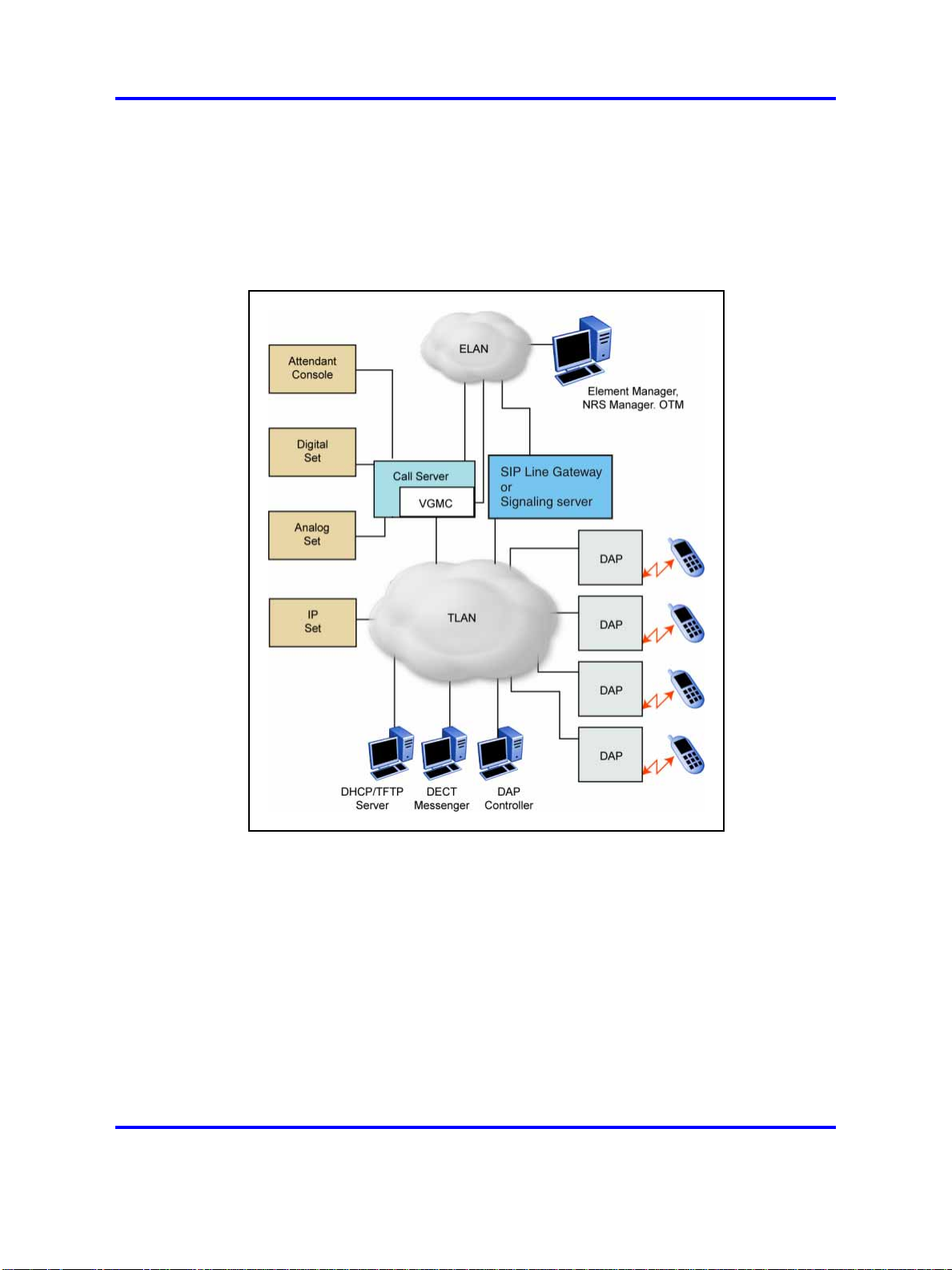
The following figure shows a general SIP DECT configuration.
Figure 1
SIP DECT configuration
You can install the DHCP or TFTP services, DECT Messenger, and DAP
controller on a single server or PC. However, you can also install them on
separate servers to enhance performance or facilitate administration. You
can also install Element Manager, NRS manager, and Telephony Manager
on the same server if the server has both a TLAN network interface and an
ELAN network interface. If the server you use cannot support all of these
applications, you can use more than one server.
You connect the DAP to the Communication Server 1000 (CS 1000)
Nortel Communication Server 1000
SIP DECT Fundamentals
NN43120-123 02.02 30 March 2010
Copyright © 2008-2010 Nortel Networks. All Rights Reserved.
Page 12

12 Product overview
• in SIPN configuration using the SIP trunks that you configure between
• in SIPL configuration using the SIP-line trunks that you configure for
Each DAP communicates with the subscribed DECT handsets in the
coverage area, and each DAP interacts with the CS 1000 and with other
configured DAPs in the company network.
You can run SIP DECT on the following configurations:
• Communication Server 1000M or Communication 1000E
• Signaling Server running SIP Gateway (SIPN only) or Signalling Server
Use the SIP Redirect Server or SIP Proxy Server to perform the
appropriate NRS configuration for SIP DECT (SIPN connection type):
•
the Signaling Server and the NRS
SIP Line Gateway
running SIP Line Gateway
You can run SIP Redirect Server on Internet Server Platform (ISP)
1100s, Call Processor Pentium Mobile (CP PM) signaling servers,
or on IBM or HP Commercial-off-the-shelf (COTS) servers under
VxWorks.
• You can run SIP Proxy Server on IBM or HP COTS servers under
Linux. You can run SIP Redirect Server on the same Signaling Server
as SIP Gateway dedicated to SIP DECT.
•
You can run SIP Redirect Server on a stand-alone Signaling Server.
If you install SIP Proxy Server you must use a stand-alone COTS server.
You cannot run SIP Gateway on the same server as the SIP Proxy Server.
Universal extension support
DECT handsets subscribed on DAPs are external to CS 1000. The CS
1000 does not control the state of DECT handsets. Therefore, the CS
1000
• cannot detect individual key presses on DECT handsets
• cannot control cadences on DECT handsets
• cannot detect if a DECT handset is switched off and on
• cannot control the handset display content
A DECT handset subscribed on a DAP cannot use the same range of
features available to analog, digital, or UNIStim IP phones on the CS 1000.
The Universal Extension (UEXT) feature on the Call Server provides
Configuration and status information for subscribed DECT handsets.
Nortel Communication Server 1000
SIP DECT Fundamentals
NN43120-123 02.02 30 March 2010
Copyright © 2008-2010 Nortel Networks. All Rights Reserved.
Page 13

Overview of SIP DECT 13
No Associated Telephone (AST) or Computer-Telephone Integration (CTI)
capabilities are currently available for SIP DECT.
Each DECT handset has a local Directory Number (DN) in CS 1000. Use
this local DN to subscribe the corresponding DECT handsets on the SIP
DECT system through DAP Manager. DAP manager is available on the
server where you installed the DAP controller.
Configure the UEXT associated with a DECT handset as follows:
•
For the Primary DN of the UEXT (key 0 SCR), enter the local DN
associated with the DECT handset.
•
On SIPN configurations, for the Target DN of the UEXT (key 1 HOT P),
enter the digits required to access the SIP route (SIP Trunks)
configured to access DAPs plus the local DN of the handsets. This
consists of one of the following values:
— For access based on the configured Coordinated Dialing Plan
(CDP), compose the Target DN as follows:
<TSC>+<LOCAL DN>.
—
For access based on the configured Uniform Dialing Plan (UDP),
compose the Target DN as follows:
<AC1 or AC2>+<LOC>+<LOCAL DN>.
•
For SIPL configuration for the Target DN of the UEXT (key 1 HOT U),
enter the digits of the User agent prefix (SIP Line configuration item)
plus the local DN of the handsets.
A UEXT corresponding to a DECT handset on the SIP DECT system
reflects the idle or busy status of the associated handset by a check for a
call processed between the handset and a DAP.
The Integrated SIP DECT provides the following UEXT features.
•
Make and receive simple calls
• Call Hold. Only one active call and one call on hold can exist for a
handset
• Consultative or Announced Call Transfer
• Blind Call Transfer
• Conference call participation if another party adds the DECT handset
to the conference
• Start a three-way call (SIPL configurations only)
• Calling Line ID (CLID) and Calling Party Name Display (CPND) for
simple calls not involving call transfer
Nortel Communication Server 1000
SIP DECT Fundamentals
NN43120-123 02.02 30 March 2010
Copyright © 2008-2010 Nortel Networks. All Rights Reserved.
Page 14

14 Product overview
• CLID and CPND for an internal line (digital or IP phone with display)
• Sending DTMF tones through the established connection to interact
• Support for a voice mailbox on CallPilot and Message Waiting
• Call Forward No Answer
•
•
• Hunting
• Call Restrictions applicable to a UEXT
•
DECT handset features
The user of a DECT handset subscribed on SIP DECT can perform the
following actions:
calling to or receiving a call from a DECT handset
with the called line (party), for example, to work with CallPilot
Indication (MWI)
Call Forward By Time of Day
Call Forward Busy
Twinned configuration (typically a desk phone plus a DECT handset)
• Make calls to DNs except restricted or blocked DNs.
•
Receive and answer calls from the Call Server. If CPND is available,
the name of the caller and DN appear on the handset display. The
position and appearance of the name DN on the display depend on the
firmware installed on the handset.
•
Place the active call on hold by pressing the R key on the handset.
Return to the held call by pressing the R key. If a call is on hold,
another call can be made from the handset. After the second call is
established, the user can switch between the two calls with the R key.
•
Transfer a call to another DN
— To perform a Blind Transfer
Place the current call on hold, call the required DN and immediately
release from the call.
— To perform a Consultative Transfer
Place the current call on hold, call the required DN, wait for the
answer and release the call after the DN answers.
• Press digit keys on the handset during an established call to transmit
DTMF tones to the other party on the call.
• For SIPL configurations only, you can initiate a three-way call. Place
an active call on hold, call the third party and wait until the call is
answered. Press the star (*) key to start the conference.
Nortel Communication Server 1000
SIP DECT Fundamentals
NN43120-123 02.02 30 March 2010
Copyright © 2008-2010 Nortel Networks. All Rights Reserved.
Page 15

If your system uses SIPN, you cannot use a DECT handset to configure
Call Forward or Hunting or to configure Call Restrictions. If the system
uses a twinned configuration, you can use the twinned desk phone to
configure Call Forward for the Primary DN with the existing keys or with
Flexible Feature Codes (FFC).
On SIPL configurations, you can activate FFC features such as Call
Forward, Make Set Busy, Ring Again, Call Park, which are available for
SIP Line users.
CallPilot and Message Waiting Indication support
DECT handsets subscribed on SIP DECT can use CallPilot.
You can configure Call Forward No Answer for the Primary DN of the
UEXT so that the unanswered calls on the corresponding DECT handset
or IP phone (in the case of a twinned configuration) are forwarded to
CallPilot. Calls can also be forwarded to CallPilot as busy treatment for
the Primary DN.
A user can call the CallPilot system from a DECT handset and log on to
the voice mailbox with the corresponding DN and password. The user can
then use the voice menus of the system as usual.
Overview of SIP DECT 15
The system can send MWI to the DECT handset through the SIP Trunk.
If your system uses SIPL, enter the MWI primary DN of the SIP DECT
user. For SIPN configurations, configure additional DNs (to which CallPilot
sends MWI) for the voice mailbox corresponding to the UEXT Primary DN.
The additional DN configured in CallPilot is the external DN of the DECT
handset, which is the Target DN on the UEXT corresponding to the DECT
handset.
CS 1000 supports only the Unsolicited MWI NOTIFY model. An external
SIP UA cannot SUBSCRIBE to MWI NOTIFY messages and cannot
request the current status of MWI for the DN from the system (by sending
SUBSCRIBE messages). Instead, a SIP UA must be ready to receive MWI
NOTIFY messages from the system even if it did not SUBSCRIBE, and it
must update MWI according to those messages only.
For SIPN configurations, due to the Unsolicited MWI NOTIFY model used
in SIPN, the DECT handset relies on the MWI notifications sent by CS
1000. Therefore, the MWI based on the existing mechanism can be in the
incorrect state on the DECT handset if the handset was turned off and
on. The MWI can be in the incorrect state if the handset leaves and then
reenters the coverage area of the SIP DECT. In this situation, the MWI on
the DECT handset returns to the correct state when the next MWI state
change occurs in the CallPilot system.
Nortel Communication Server 1000
SIP DECT Fundamentals
NN43120-123 02.02 30 March 2010
Copyright © 2008-2010 Nortel Networks. All Rights Reserved.
Page 16

16 Product overview
If you use a twinned configuration for a DECT handset, the corresponding
IP or TDM phone correctly reflects the current state of MWI, if it receives
MWI notifications for the Primary DN from CallPilot.
SIP DECT capacity limitations
The following capacity limitations apply to SIP DECT:
•
•
• a maximum of 6000 DECT handsets on each SIP DECT system
• a maximum of 1000 simultaneous calls on each network
• a maximum of 25 subscription records for each DAP
a maximum of 12 simultaneous calls for each DAP
a maximum of 256 DAPs on each network (where handover and
synchronization between DAPs is possible)
(potentially, several isolated SIP DECT systems can connect to CS
1000)
If the planned number of DECT handsets in a SIP DECT system is
equal to M, and the number of DAPs in that system is equal to N, M
must be less than or equal to N*25.
Consider the following additional capacity limitations based on the CS
1000 configuration characteristics.
•
The number of available UEXTs is limited by the number of available
virtual Telephone Numbers (TN) in the system.
•
The number of DNs available for DECT handsets depends on the
configured dialing plan and the availability of the Directory Number
Expansion (DNXP) package (150).
Nortel Communication Server 1000
SIP DECT Fundamentals
NN43120-123 02.02 30 March 2010
Copyright © 2008-2010 Nortel Networks. All Rights Reserved.
Page 17

.
Site planning and hardware
deployment
Navigation
“Components of SIP DECT systems” (page 17)
•
• “Deployment requirements” (page 18)
•
"Types of SIP DECT configuration" (page 28)
•
“Site planning” (page 32)
•
“System deployment” (page 38)
Components of SIP DECT systems
This section contains information about the following topics.
•
“Call server, Signaling server, and SIP Line Gateway” (page 17)
17
•
“PC (DAP controller)” (page 18)
•
“DECT Access Points” (page 18)
Call server, Signaling server, and SIP Line Gateway
Before you install SIP DECT you must install and configure a CS 1000
system, as follows:
• For SIPN configuration, install Call Server and Signaling Server.
• For SIPL configuration, install Call Server and SIP Line Gateway.
For more information about SIP Line Gateway, see SIP Line Fundamentals
(NN43001-508).
CS 1000 Release 6.0 introduces the CP PM Co-resident Call Server
and Signaling Server (CP PM Co-res CS and SS), which can run the
Call Server software, the Signaling Server software, and the System
Management software on the same hardware platform operating under
the RedHat Linux operating system.
Nortel Communication Server 1000
SIP DECT Fundamentals
NN43120-123 02.02 30 March 2010
Copyright © 2008-2010 Nortel Networks. All Rights Reserved.
Page 18

18 Site planning and hardware deployment
For more information about CS 1000 installation, see Communication
Server 1000E Installation and Commissioning (NN43041-310).
PC (DAP controller)
Minimum specifications for the DAP controller PC are as follows.
•
2.4 GHz CPU
•
512 MB RAM
•
CD-ROM drive
• 1GB free hard disk space
DECT Access Points
Two models of DECT Access Points (DAP) are currently available for
Nortel SIP DECT: C4710 and C4710E. The C4710E is a special version
of the C4710 Access Point that provides an alternative with an external
antenna connection for outdoor use.
•
C4710 DAP
— PEC: NTCW26AAE5
—
CPC: N0162007
•
C4710E DAP
—
PEC: NTCW26BAE5
—
CPC: N0162008
ATTENTION
The only audio codec supported on the C4710 and C4710E DAPs is the G.711
codec. Ensure that the G.711 codec is available in your system.
It is not possible to make calls between the Nortel IP Softphone 2050 and DECT
handsets when you select the I use a modem to connect to the network
check box in the Audio settings for the softphone. If you select this setting, the
Nortel IP Softphone 2050 uses the G.729 codec for all calls.
When using Multimedia PC Client, ensure that you select Medium Speed or
High Speed in the Multimedia PC Client Connection preferences if you plan to
make calls between DECT handsets and Multimedia PC Clients.
Ensure that the DAPs are installed according to the location
recommendations. For more information, see “Deployment requirements”
(page 18).
Deployment requirements
This section describes SIP DECT deployment requirements.
Nortel Communication Server 1000
SIP DECT Fundamentals
NN43120-123 02.02 30 March 2010
Copyright © 2008-2010 Nortel Networks. All Rights Reserved.
Page 19

Navigation
• “Radio synchronization” (page 19)
• “IP network configuration” (page 23)
•
“Location requirements” (page 26)
Radio synchronization
The radio network structure supports seamless handover of existing calls.
This means that, during a call, if a handset moves from the coverage area
of one DAP into the coverage area of another DAP, the new DAP can
take over the call. The call is not interrupted, and the user is not aware of
the handover. In the traditional DECT system, synchronization between
DAPs occurs over the wired network. SIP DECT requires an accurate
synchronization of the radio signals in the air to support handover.
ATTENTION
If a DAP cannot receive synchronization signals from at least one other DAP, it
operates in a single cell mode and cannot handover to other DAPs or receive
handover from them.
Deployment requirements 19
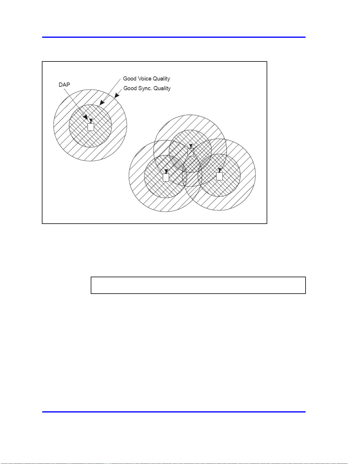
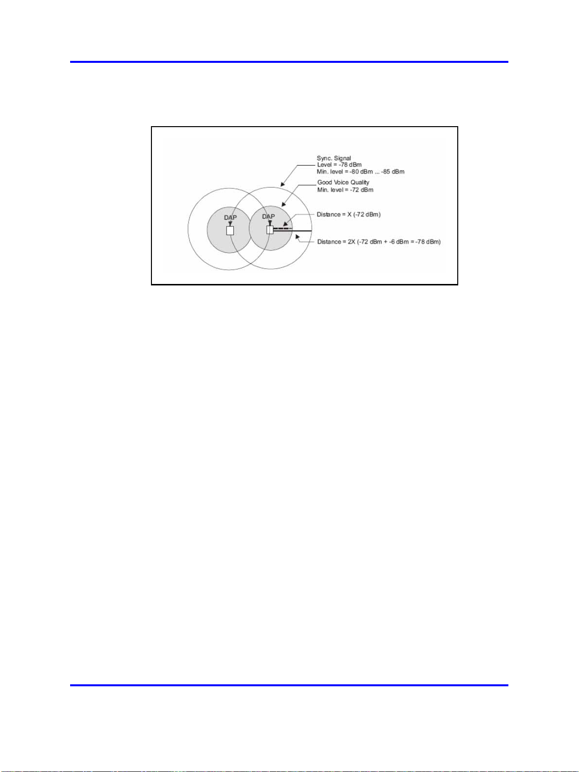
Represent each DAP cell as a circle indicating the radio signals around
the DAP. Figure 2 "DAP radio signal synchronization" (page 20) shows
two circles around the DAP.
•
an inner circle in which sufficient radio signal strength exists for
acceptable voice quality
•
an outer circle in which sufficient signal strength exists for
synchronization, but not enough for acceptable voice quality
Nortel Communication Server 1000
SIP DECT Fundamentals
NN43120-123 02.02 30 March 2010
Copyright © 2008-2010 Nortel Networks. All Rights Reserved.
Page 20
20 Site planning and hardware deployment
Figure 2
DAP radio signal synchronization
Due to the cellular structure of a DECT radio network, overlap exists in
the cells with sufficient voice quality. The wider cell limit around the DAP
therefore has some overlap with the other cell and reaches to the radio of
the other cell. Consequently, the DAPs of the overlapping cells exchange
radio signals. These radio signals are weak relative the signal needed by
the handsets, but are strong enough for synchronization.
ATTENTION
For signal strength calculation see “Signal strength and frame errors” (page 22).
If one DAP receives a signal from another, the receiving DAP checks the
radio signals on Primary Access Right Identity (PARI), to ensure that the
signals belong to the same DECT system. If the signals belong to the
same DECT system, the DAPs synchronize according to user-configured
rules.
Nortel Communication Server 1000
SIP DECT Fundamentals
NN43120-123 02.02 30 March 2010
Copyright © 2008-2010 Nortel Networks. All Rights Reserved.
Page 21
Deployment requirements 21
ATTENTION
If two or more independent SIP DECT systems have overlapping coverage
areas, configure these systems so each has a unique subset or portion of
carriers. When each system has a unique subset of carriers, interference
between the systems is reduced.
Reducing the number of available carriers reduces the maximum number of
simultaneous calls in the DECT system. To achieve your desired call capacity,
you can be required to install extra DAPs. For more information, see step 4 of
Configuring DECT Settings.
The DAPs transmit with a minimum of two channels carrying primary voice
and data, also named bearers. If no voice calls occur over a DAP, the
DAP transmits two dummy bearers. If one or more voice calls occur on the
DAP, one is one a dummy bearer, while the others are voice calls.
Synchronization hierarchy
If two or more DAPs belong to the same system, the DAPs automatically
synchronize using a hierarchical structure. In most cases synchronization
is automatic, but if your system has a complex DAP cell structure, you
must manually configure synchronization.
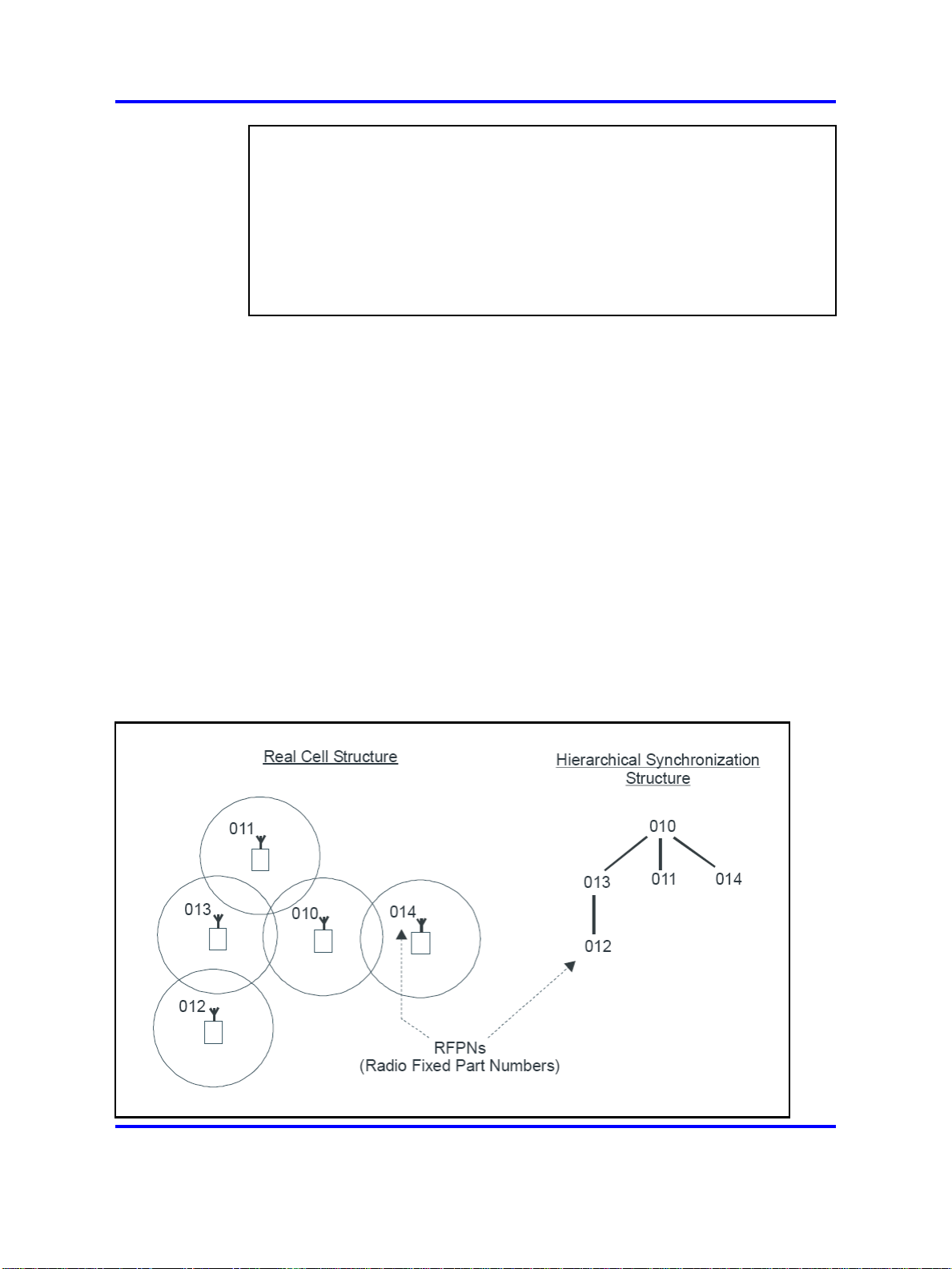
The DAP controller tracks the synchronization structure and assigns each
DAP a unique Radio Part Number (RPN) after the DAP starts the first time.
One or more DAPs act as a synchronization source to form the root of
the hierarchical structure, as illustrated in Figure 3 "DAP synchronization
hierarchy" (page 21).
Figure 3
DAP synchronization hierarchy
Nortel Communication Server 1000
SIP DECT Fundamentals
NN43120-123 02.02 30 March 2010
Copyright © 2008-2010 Nortel Networks. All Rights Reserved.
Page 22
22 Site planning and hardware deployment
If more than one synchronization source is present, each one forms a
separate hierarchy of DAPs called a synchronization island.
Automatic synchronization occurs within each synchronization island using
the following rules.
•
After a DAP starts, it searches for existing DAPs. If it finds one with a
lower RPN, it synchronizes with it. If no other DAP exists with a lower
RPN, the new DAP becomes the synchronization source.
ATTENTION
Extra DAPs can be required to establish a synchronization path.
• If a DAP detects more than one other DAP, it synchronizes with the
DAP with the shortest path to the synchronization master. If two or
more DAPs have the same path length separating them from the
master, the new DAP synchronizes to the DAP with the lowest RPN.
ATTENTION
After you install SIP DECT, wait at least 15 minutes until you see the results of
the automatic synchronization.
To make a DAP a synchronization master or to give a DAP a higher
position in the synchronization structure, you can manually assign a lower
RPN number to a DAP. You can manually assign RPNs using the DAP
Manager Web interface. Automatically assigned RPNs start at 010. If you
manually assign a new RPN, ensure that it is in the range 000 to 00F.
ATTENTION
You must determine the position of the Synchronization Master before you start
site planning. Place the synchronization master, which is the DAP with the
lowest RPN, in the middle of your site, building, or buildings.
Signal strength and frame errors
Signal strength is important for DAP-handset communication (voice quality)
and synchronization between DAPs. The following items are relevant for
the signal strength for synchronization.
• To achieve a good voice quality, the minimum signal strength at the
receiver in the handset and DAP must be --72 Decibels (referenced to
milliwatts) (dBm). This includes a margin of --10 dBm for fast fading
dips.
• Synchronization is possible if the strength of the received signal from
another DAP is --80 dBm to --85 dBm. This is adjustable.
• In an open area, the distance is doubled if the received signal strength
is 6 dB lower. This means that at a minimum signal strength for good
voice quality of --72 dBm and a distance X, the signal strength at the
Nortel Communication Server 1000
SIP DECT Fundamentals
NN43120-123 02.02 30 March 2010
Copyright © 2008-2010 Nortel Networks. All Rights Reserved.
Page 23
Deployment requirements 23
double distance, 2X, is --78 dBm. For more information, see Figure 4
"Signal strength considerations" (page 23).
Figure 4
Signal strength considerations
•
An open area has more than sufficient signal strength for
synchronization. The expected level at the double distance is --78
dBm. The required level is --80 dBm to --85 dBm. This leaves a safely
margin of 2 to 7 dB.
• Obstructions between the DAPs can introduce loss. Also, many objects
cause reflections that let the signal reach the DAPs through other path
with sufficient signal strength.
• In rare cases, factors in the surrounding environment can cause
the error rate in the received frames to be temporarily much higher
than is normal for speech. An occasionally elevated error rate does
not indicate a problem with your SIP DECT system. However, if you
consistently see a high error rate, then there is a problem with the
deployment of your SIP DECT system.
Frame errors
Frame errors rarely can occur in DECT. The number of frame errors for
each reading may not be more than four. The most common cause of
frame errors higher than four is a high number of reflections. This causes
an audible click during calls.
IP network configuration
The IP network must be able to support SIP DECT; this section provides
information about planning an IP network that is suitable for supporting
SIP DECT.
Nortel Communication Server 1000
SIP DECT Fundamentals
NN43120-123 02.02 30 March 2010
Copyright © 2008-2010 Nortel Networks. All Rights Reserved.
Page 24

24 Site planning and hardware deployment
SIP DECT typically uses existing IP network infrastructure and facilities
for the network connection. For IP connectivity, you must configure the
network to ensure that all SIP DECT components have the following
characteristics:
•
are equipped with unique IP addresses (some static, some dynamic)
•
can reach all the required services
•
can be reached by all clients and counterparts
Ethernet requirements
The following items describe the Ethernet requirements.
• The IP network must offer a Quality of Service (QoS) that is sufficient
to support the SIP DECT Voice over IP.
• The IP network must support transparent IP multicast between all
DAPs and the DAP controller.
•
Connect only one DAP to one IP Switch port.
• DAP supports full duplex and supports autonegotiation if DAP is
connected to a port on an Ethernet Switch.
ATTENTION
Configure the Ethernet switch ports to which the DAPs are connected to use
autonegotiation. If the switch does not support autonegotiation, you can use
full-duplex; however SIP DECT can operate incorrectly on some switches
when you configure them to use full-duplex.
•
Ensure that enough unique IP addresses are available to support both
data networking traffic and SIP DECT components. You can configure
private IP addresses for local traffic, and you can configure private IP
addresses on the local network to connect to public IP addresses if you
use Network Address Translation (NAT). However, SIP DECT does
not support NAT.
•
Ensure that IP addresses and routing are consistent with each other
to deliver the required transparency. Also ensure that IP addresses
are consistent with routing for normal unicast traffic as well as for the
required multicast traffic.
• The maximum cable length between the DAP and IP network
equipment, such as a switch, is 100 meters for a Category 5,
unshielded twisted-pair, half-duplex cable. If the required cable length
between the IP network equipment and the DAP exceeds 100 meters,
use Long Range Ethernet equipment in the connection. Several
manufacturers offer such a solution, which allows cable lengths of
more than one kilometer (km).
Nortel Communication Server 1000
SIP DECT Fundamentals
NN43120-123 02.02 30 March 2010
Copyright © 2008-2010 Nortel Networks. All Rights Reserved.
Page 25

Deployment requirements 25
Fixed IP network addresses
You must provision fixed IP addresses for the following servers:
•
The TFTP server stores the configuration file and the firmware that are
available to the DAPs. After a DAP starts up, the DHCP server sends
the DAP the IP address of the TFTP server. The DAP then downloads
the configuration files from the TFTP server. The TFTP server often
runs on the DAP controller or manager PC.
• The DHCP server (optional) sends the address of the DNS server to
the DAP. The DAP does not support Domain Name Resolution.
• The DAP controller or manager requires a fixed IP address. The DAPs
retrieve this fixed IP address from the configuration file that the DAP
loads from the TFTP server.
• The IP address of the PABX is reachable either through a router or
directly.
The PABX is sometimes referred to as Gatekeeper or SIP proxy,
depending on the type of PABX that is used.
To facilitate network management, Nortel recommends that fixed IP
addresses are also assigned by the DHCP server. Ensure that the DHCP
server has the hardware MAC addresses of all servers to issue the proper
(fixed) IP addresses to each individual server.
The DAP IP address can be stored in flash memory. If the IP address is
stored, the DHCP server is needed only for the first startup. Then an IP
address is assigned to the DAP.
Dynamic IP network addresses
Network stations, which are not servers (PC workstations and DAPs), can
use dynamic IP addresses assigned by DHCP. For dynamic IP addresses,
you need not specify the MAC addresses of all the network stations in the
DHCP server.
Ensure that you configure the DHCP server to assign IP addresses from
a specific range to unknown MAC addresses. However, unknown LAN
stations have valid IP addresses, which can be a minor network security
issue. To solve this, use the Vendor Class Identification (VCI) in the DHCP
server. The DHCP server issues IP addresses only to devices that have
the DAP VCI. Ensure that the DHCP server can make a distinction in VCIs.
The DAP VCI is D(ECT)AP 49.
ATTENTION
For SIPN configurations, ensure that a static IP address is issued to the DAP
selected as the DAP Redirect Server. For more information, see “Adding
Gateway Endpoint for DAP redirect server” (page 136).
Nortel Communication Server 1000
SIP DECT Fundamentals
NN43120-123 02.02 30 March 2010
Copyright © 2008-2010 Nortel Networks. All Rights Reserved.
Page 26

26 Site planning and hardware deployment
Each DAP in a SIP DECT system is assigned a dynamic IP addresses by
the DHCP server. You can configure the DAPs to store the IP address
in flash memory, so the DHCP server is required only during the initial
configuration of the system.
Multicast addresses
SIP DECT uses Multicast addresses for the following functions:
•
Communication between the SIP DECT network components to locate
or address a handset.
If a handset must be reached, the request must simultaneously go
to all DAPs. For example, if you use the page function during an
incoming call, a single multicast message is sent to all DAPs to find the
DAP for your handset quickly and efficiently.
•
Seamless handover from one DAP to the other
If inter-cell handover is necessary, the media path must be redirected
from the existing DAP to another DAP. The handset always initiates
a handover. The handset sends request to another DAP (not the
DAP with the current connection). This DAP issues a multicast on
the network to determine on which DAP the voice connection exists.
The DAP, with the existing voice connection, responds and then the
connection can be redirected from the DAP with the existing voice
connection to the new DAP.
•
Synchronization between DAPs
You must configure multicast before synchronization can occur
between DAPs in the SIP DECT system.
All network components must support forwarding of IP multicast packages.
The IP DECT Configurator proposes a default multicast IP address
(239.192.49.49). This is a multicast address in the private multicast IP
address range for use in private IP networks. If you are not sure you can
access this address, contact the local IT manager.
ATTENTION
You must disable IGMP Snooping and Spanning Tree Protocol on switch ports
where SIP DECT equipment is connected.
Location requirements
Comply with the following requirements for DAP location:
• Ensure that the location complies with local electrical codes.
• Install DAPs indoors where no condensation occurs and the
temperature remains within the range of 0
• Install DAPs in a vertical position. The radiation pattern differs between
the horizontal and vertical positions.
Cto40C.
Nortel Communication Server 1000
SIP DECT Fundamentals
NN43120-123 02.02 30 March 2010
Copyright © 2008-2010 Nortel Networks. All Rights Reserved.
Page 27

Deployment requirements 27
• Do not mount a DAP to a metal surface.
• Do not roll up the extra cabling behind a DAP.
• Position DAPs upright on walls. DAPs must be at least 30 cm from the
ceiling.
• Position DAPs at least 1 meter (m) from large concrete or stone
columns and from major building structural members such as support
beams or columns.
•
Position the DAPs high enough to clear obstructions between the
DAPs and the cell edge close to the ceiling.
• Mount the DAPs clear of obstacles such as pipes or ducts.
To install the DAPs outdoors, see “External housing installation” (page
275).
DAP power configuration
DAPs are powered using one of the following methods:
•
Locally using an RJ-11 connector. The AC voltage must be 40V (+ or
--10 percent). Use an AC adaptor that provides at least 10 Watts. For
part numbers of available AC adaptors, see Table 1 "Part numbers"
(page 27).
Table 1
Part numbers
NTCW28AAE5 N0162030 DAP AC/AC adaptor Eur
NTCW28BAE5 N0162032 DAP AC/AC adaptor UK
NTCW28CAE5 N0162033 DAP AC/AC adaptor ANZ
•
Through Power over Ethernet (PoE) as defined by IEEE802.3af
specifications. The DAPs support both phantom power and power over
spare wires. The following specifications apply to PoE power.
— Minimum 36 Volts and maximum 60 Volts of voltage at the DAP
—
Standard RJ-45 connector, using the spare wires pins (wires)
— Maximum cable length of 100 meters
Both phantom power and power over spare wires are provisioned on the
same DAP to provide system redundancy. The power input providing the
highest voltage is active. If one power input fails, the other takes over
without service interruption.
Nortel Communication Server 1000
SIP DECT Fundamentals
NN43120-123 02.02 30 March 2010
Copyright © 2008-2010 Nortel Networks. All Rights Reserved.
Page 28
28 Site planning and hardware deployment
Types of SIP DECT configuration
You can implement SIP DECT in various system configurations to
accommodate your needs. The most common SIP DECT configurations
are as follows:
•
Basic (or Simple) Configuration
• Routed Head Quarter Configuration
•
Branch Office Configuration
• Routed Head Quarter Configuration with Branch Office
• Multi Site Mobility Network Configuration
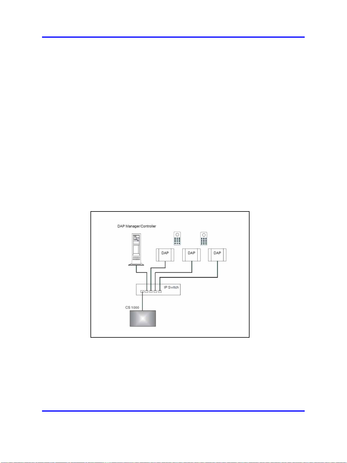
Basic (or Simple) Configuration
•
In Basic Configuration all DAPs are in the same subnet that is
based on one or more IP switches. IP multicast must be able to
occur between all DAPs. The configuration supports seamless
handover between all DAPs. For an illustration of a simple SIP DECT
configuration, see Figure 5 "Simple SIP DECT network configuration"
(page 28).
Figure 5
Simple SIP DECT network configuration
• Routed Head Quarter configuration
Routed Head Quarter Configuration is used for a Large Campus
network that is split into several subnets. In this configuration DAPs
belong to various subnets and behave as one large SIP DECT system
with the full support of seamless handover. IP multicast must be able
to occur between all DAPs in the Campus network, through IP switches
and the IP routers that connect the various subnets. For an illustration
Nortel Communication Server 1000
SIP DECT Fundamentals
NN43120-123 02.02 30 March 2010
Copyright © 2008-2010 Nortel Networks. All Rights Reserved.
Page 29
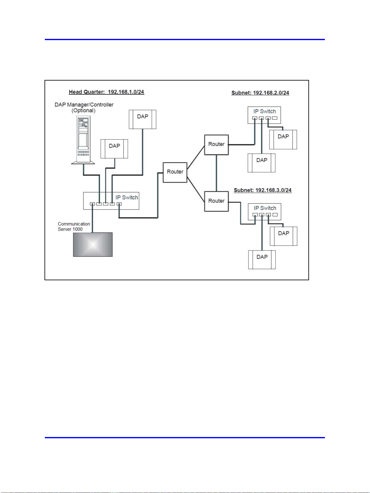
of a Routed Head Quarter configuration, see Figure 6 "SIP DECT
configuration Routed Head Quarter" (page 29).
Figure 6
SIP DECT configuration Routed Head Quarter
Types of SIP DECT configuration 29
In Routed Head Quarter Configuration network settings must comply
with the following requirements:
— The network must support Quality of Service (QoS) and IP
connectivity throughout the Campus.
— Routers must support IP multicast routing.
— The IP multicast address for SIP DECT must be the same in all
subnets.
— Multicast Time to live (TTL) must be greater than 1.
— In the SIP DECT configuration, you must use an “aggregated”
subnet mask that covers all the subnets where DAPs are present.
For instance, if each subnet is defined by mask 255.255.255.0,
then “aggregated” mask 255.255.248.0 covers up to four such
subnets.
• Branch Office Configuration
Nortel Communication Server 1000
SIP DECT Fundamentals
NN43120-123 02.02 30 March 2010
Copyright © 2008-2010 Nortel Networks. All Rights Reserved.
Page 30
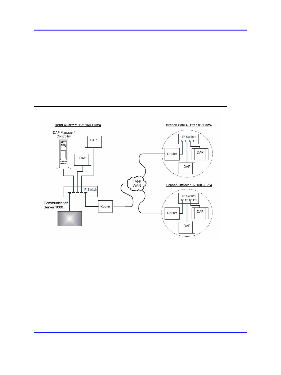
30 Site planning and hardware deployment
Branch Office Configuration is used for a Large Campus network
that is split into various (geographical) segments (branch offices). IP
multicast must be able to occur between all DAPs in every branch
office and no IP multicast is allowed between any two branch offices.
In this configuration, each branch office behaves as an isolated site
of a large SIP DECT system. Branch Office configuration supports
seamless handover within each isolated site (branch office), but not
between sites. Support is unavailable for roaming between branch
offices. For an illustration of a Branch Office Configuration, see Figure
7 "Branch Office Configuration" (page 30).
Figure 7
Branch Office Configuration
For Branch Office Configuration, network settings must comply with
the following requirements:
— The network between Branch Offices and Call Server must support
QoS.
— Branch Offices must be in separate subnets (IP router(s) needed).
— DAPs in various Branch Offices must be located so that no
synchronization can occur between any two DAPs belonging to
various Branch Offices.
— Routers must block IP multicast between Branch Offices (multicast
TTL = 1, which means that IP multicast packets do not cross IP
routers).
Nortel Communication Server 1000
SIP DECT Fundamentals
NN43120-123 02.02 30 March 2010
Copyright © 2008-2010 Nortel Networks. All Rights Reserved.
Page 31

Types of SIP DECT configuration 31
• Routed Head Quarter Configuration with Branch Office
Routed Head Quarter Configuration with Branch Office makes it
possible to create a Routed Head Quarter Configuration in one (and
only one) the branch office. Within the Branch Office with Routed Head
Quarter, DAPs belong to various subnets and behave as a single site
of one SIP DECT system with the full support of seamless handover.
As for the whole SIP DECT system, each Branch Office (including the
Branch Office with Routed Head Quarter) behaves as isolated site of
that SIP DECT system. Branch Office configuration supports seamless
handover within each isolated site (branch office), but not between
sites. Support is unavailable for roaming between branch offices.
Figure 8
Routed Head Quarter Configuration with Branch Office
In Routed Head Quarter Configuration with Branch Office the network
settings must comply with the requirements for Routed Head Quarter
configuration (for the network settings within Routed Head Quarter)
and with the requirements for Branch Office configurations (for the
network settings between Branch Offices, including the Branch Office
with Routed Head Quarter).
• Multi Site Mobility Network Configuration
Multi Site Mobility Network (MSMN) Configuration makes it possible
to use portable DECT handsets on various MCDN nodes where each
node is a CS 1000 system plus the corresponding SIP DECT system.
MSMN allows roaming between independent SIP DECT systems
installed on separate Call Servers (connected by trunks). Handover
between independent SIP DECT systems is not possible.
Nortel Communication Server 1000
SIP DECT Fundamentals
NN43120-123 02.02 30 March 2010
Copyright © 2008-2010 Nortel Networks. All Rights Reserved.
Page 32

32 Site planning and hardware deployment
A SIP DECT system on an individual MCDN node can be any of the
previously described configurations: Basic (Simple), Routed Head
Quarter, Branch Office, or Routed Head Quarter with Branch Office.
Site planning
Site planning is an information gathering process that begins with a site
survey and ends with deploying SIP DECT. The information received in the
site survey determines customer requirements and the number of cells
required to support traffic.
You can use the Location builder tool (a part of the DAP controller
software package) to plan your site. For more information, see “Location
builder tool” (page 247).
Site survey
• Site maps
Site maps are an essential requirement in advance of a survey. A
map of the complete site (if more than one building) and plans of each
floor of each building are required. Make sure that dimensions are
clearly stated on the maps. Additional information such as the use of
buildings (office, hotel, factory, store), construction materials (walls,
floors, ceilings), and cabling infrastructure are helpful in estimating
DAP positions in advance.
• Number of users (handsets)
Number of users (handsets), both initial and foreseeable growth, and
areas of above average and below average traffic density.
•
Allowed and prohibited DAP positions
A customer can prohibit the installation of DAPs in certain areas, or
require that DAPs be installed out of sight.
•
Details of required coverage
Determine to what areas coverage must extend; for example:
elevators, stairwells, toilets, outdoor areas.
• Position of the DECT System and available cabling
Ensure that you can use existing cabling for the connection between
the DECT System, and that the DAP cables meet or exceed the UTP
Cat 5 standard. If the type and quality of the available cabling is not
sufficient for the connection and limits the maximum distance between
the DAP and DECT System, you may require new cabling.
• Sensitive electronic equipment
Check whether sensitive electronic equipment is present, for example,
laboratory or medical equipment. Although the transmitted power of
Nortel Communication Server 1000
SIP DECT Fundamentals
NN43120-123 02.02 30 March 2010
Copyright © 2008-2010 Nortel Networks. All Rights Reserved.
Page 33

the DAPs is low (about 250 mW), it can interfere with some sensitive
electronic equipment.
•
Traffic information
Gather information about user density, amount of traffic, and whether
redundancy is required. You require this information to determine the
number of DAPs that are required and therefore the required cabling.
A DAP must always have at least one channel free to allow handover
(either intracell or intercell handover). Make sure that the maximum
expected traffic density is not more than 11 channels simultaneously.
For more information, see “Site survey example” (page 257).
Speech quality
A relationship always exists between coverage and speech quality.
The greater the distance between the handset and the DAP, the lower
the quality. Therefore, you must understand the relationship between
the coverage and the expected voice quality. For an illustration of the
relationship between coverage and voice quality in an open environment,
see Figure 9 "Coverage and speech quality in an open environment."
(page 33).
Site planning 33
Figure 9
Coverage and speech quality in an open environment.
Be aware that DECT is a digital communication system. It incorporates a
“transmission errors hiding” system. This means that it tries to hide the
transmission errors. The results of this mechanism are as follows:
Nortel Communication Server 1000
SIP DECT Fundamentals
NN43120-123 02.02 30 March 2010
Copyright © 2008-2010 Nortel Networks. All Rights Reserved.
Page 34

34 Site planning and hardware deployment
• A small incidental transmission error is not noticeable in speech.
• A minor transmission error causes audible clicks during speech.
• A major transmission error causes the loss of speech.
The following factors effects the voice quality as well:
• Moving speed
The DECT techniques allow a maximum moving speed of 5 kilometers
per hour (km/h). Bear this in mind if your DECT system must cover an
elevator.
•
Metal Construction
In metal structures, reflection can negatively impact voice quality (clicks
and interruptions can occur) even if you are close to the DAP. This
effect is made worse when the handset is in motion.
For more information see “Coverage calculation” (page 35).
The required quality depends on the customer requirements and the
environment. The following are the various quality levels:
•
Excellent and good
In business, office, and first aid environments, the excellent and good
voice quality is required to avoid dropped calls, inherent sounds, or
pauses in important conversations. Any sounds produced by a lower
quality level noticed by the system users, because these environments
are usually quiet or produce less background noise.
•
Satisfactory
In less critical areas like basements, stock rooms, and cold stores, the
satisfactory quality level is usually accepted because they are noisy
environments. In a noisy environment people do not notice an audible
click in a conversation, because the environment produces a lot of
background noise. This environmental background noise may also
contain audible clicks. Sometimes, the voice of a user is less audible to
the other user listening at the other end of the conversation because
of the background noise.
Use the following points as general guidelines:
• A maximum of 20 percent of the whole coverage is considered as
satisfactory.
• Install a hard-wired emergency telephone in those areas where the
quality is satisfactory. This ensures that people can always make a call
in case of an emergency.
• If you agree with the customer on lower speech quality, then make
sure that this is well documented and signed by the customer. If
Nortel Communication Server 1000
SIP DECT Fundamentals
NN43120-123 02.02 30 March 2010
Copyright © 2008-2010 Nortel Networks. All Rights Reserved.
Page 35

the customer becomes dissatisfied afterwards, you can refer to the
agreement. Also, be aware that, if the speech quality is low in certain
areas, the customer may perceive that you delivered a low-quality
system.
•
If a lower voice quality level is acceptable, ensure that all calls are
received and dropped calls are avoided.
Coverage calculation
The coverage can be calculated in advance, before executing a site
survey. Calculation is based on the following theory.
The transmission path between the DAP and the handset is subject to
radio-propagation related peculiarities, such as:
• Dynamically changing environment
•
Signal attenuation due to fixed and moving objects
•
Multi-path propagation of the signal
Site planning 35
The signal from the transmitter is attenuated in the link before it arrives
at the receiver. The link consists of a transmission path through the air
and through obstacles such as walls. The air and the obstacles cause
attenuation called insertion loss. The following table shows typical insertion
losses for some obstacles.
Table 2
Typical insertion losses of some obstacles
Material Insertion loss (dB)
Glass
Glass, metal reinforced grid
Glass, metal clad sunguard
Wall, indoor, plaster, wood
Wall, brick, 10 cm
Wall concrete, 10 cm
Wall concrete, 15 cm
Wall concrete, 20 cm, large windows
Wall concrete, 40 cm
Ceiling, concrete, reinforced, tiles
2
10
10
2
3.5
6
9
6
17
17-20
With the DECT equipment, the available link budget is 38 dB. This is the
maximum allowed loss in the link, under constraints of excellent and good
speech quality and the ability for the user to move.
Nortel Communication Server 1000
SIP DECT Fundamentals
NN43120-123 02.02 30 March 2010
Copyright © 2008-2010 Nortel Networks. All Rights Reserved.
Page 36

36 Site planning and hardware deployment
To calculate the distance between DAP and handset, use the information
in Figure 10 "DECT range calculation chart" (page 36).
Using the building map, start at the possible DAP location. Move away
from the DAP location. Calculate the distance. When you encounter
an obstacle, calculate the insertion loss. Using the chart below, start
in the lower left corner (0,0), move horizontally, to the value for the
actual distance. Move vertically to the value for the insertion loss of
the encountered obstacle. If the curve in the chart is crossed, read the
maximum distance for that specific DAP in that situation. This gives the
cell size in that specific direction. Ensure that outside the calculated
range communication is possible but a good voice quality is no longer
guaranteed.
Figure 10
DECT range calculation chart
Nortel Communication Server 1000
SIP DECT Fundamentals
NN43120-123 02.02 30 March 2010
Copyright © 2008-2010 Nortel Networks. All Rights Reserved.
Page 37

Site planning 37
The range in the air is 80 m from the DAP, for optimal communication
quality. The result of this coverage calculation is a map with possible DAP
positions indicated.
Use the following DAP ranges as a rough guide for planning the DAP
positions:
• In the line of sights the DAP has a range of approximately 80 m.
• In halls the DAP has a range less than 80 m.
•
In buildings the DAP has a range of 15 to 40 m. This is based on the
assumption that walls are made of light brick, plasterboard or wallboard
with metal frames. Normal electrical wiring, central heating pipes, office
furniture and desktop computer equipment have no significant effect.
Ensure that you consider the signal shadowing effect of stairways, lift
shafts, and shielded rooms.
The following items cause shadowing of the radio signal:
•
Thick walls, especially cavity walls and reinforced concrete walls.
•
Windows or glass in doors with steel wire reinforcement or metallic
reflection film.
•
Steel doors, partitions, or walls.
•
Fire resistant doors.
•
A wall of steel cabinets, large computer equipment or machinery.
•
Thick concrete floors.
During the site survey, be aware of the following:
•
Choose a corridor or other large open space rather than an enclosed
area so that the radio signal passes through as few walls as possible
to reach as large an area as possible.
• Radio reception inside a vehicle is poor unless the user is close to the
DAP.
• Ensure that the DAP is placed high enough to be unaffected by
surrounding objects. For example, a DAP in a car park needs to be
placed higher than a vehicle that is parked next to it.
• Ensure that DAPs are separated by at least 1 meter.
• The presence of another unsynchronised DECT System, or any similar
system in adjacent buildings, causes interference.
Nortel Communication Server 1000
SIP DECT Fundamentals
NN43120-123 02.02 30 March 2010
Copyright © 2008-2010 Nortel Networks. All Rights Reserved.
Page 38

38 Site planning and hardware deployment
• A DAP or a handset interferes with sensitive laboratory equipment
and medical equipment (for example, ensure that DAPs are installed
outside of an operating room at an hospital.)
•
Ensure that significant interference from unsuppressed engines or
electric motors is accounted for.
Traffic density calculations
Perform the traffic density calculations so that you have a low blocking
probability in the system.
For traffic calculations, you must know
• the number of users
•
the type of users
The following table lists the three user types.
Table 3
Three user types
Traffic Application Erlang/User
Average Executive and secretary
The Erlang value for DAP C4710 and C4710E (12 radio channels), with
blocking probability of 0.5%, is 5.25.
Calculate the traffic density using the following formula:
One cell has 20 users: five average traffic and 15 low traffic. The load is:
(5 x 0.15) + (15 x 0.05) = 1.5 Erlang
Therefore, one 12 channel DAP is sufficient for this cell.
System deployment
This section describes the basics of SIP DECT system deployment.
Low normal offices
groups
High help desks, Tele-services
0.05
0.1-0.15
0.2-0.25
DECT Deployment Kit 2
The DECT Deployment Tool (deployment tool) determines cell centers and
cell boundaries.
Nortel Communication Server 1000
NN43120-123 02.02 30 March 2010
Copyright © 2008-2010 Nortel Networks. All Rights Reserved.
SIP DECT Fundamentals
Page 39

System deployment 39
The DECT Deployment Kit 2 is shown in Figure 11 "Deployment Kit 2 and
carrying case" (page 39). For more information about the deployment kit,
see the DeTeWe User Manual that accompanies each kit.
ATTENTION
If you use an older deployment tool that differs from the one in the following
figure , see “Deployment tool” (page 263).
Figure 11
Deployment Kit 2 and carrying case
The following figures shows the assembled kit.
Nortel Communication Server 1000
SIP DECT Fundamentals
NN43120-123 02.02 30 March 2010
Copyright © 2008-2010 Nortel Networks. All Rights Reserved.
Page 40

40 Site planning and hardware deployment
Figure 12
Assembled Deployment Kit 2 and DeTeWe handsets
Nortel Communication Server 1000
SIP DECT Fundamentals
NN43120-123 02.02 30 March 2010
Copyright © 2008-2010 Nortel Networks. All Rights Reserved.
Page 41

Figure 13
Deployment Kit 2 basestation
System deployment 41
Use the following information in conjunction with the DeTeWe User Manual
that accompanies the deployment tool.
• The two DeTeWe handsets with the kit are subscribed to the
basestation and are numbered 13 and 15. To view the assembled
basestation and the DeTeWe handsets, see Figure 12 "Assembled
Deployment Kit 2 and DeTeWe handsets" (page 40).
• The key on the handset is the Off-Hook key.
•
To enter Site Survey Mode on the handset, perform the following
procedure.
Access site survey mode.
Procedure 1
Entering the site survey mode
Step Action
1 Press Menu.
Nortel Communication Server 1000
SIP DECT Fundamentals
NN43120-123 02.02 30 March 2010
Copyright © 2008-2010 Nortel Networks. All Rights Reserved.
Page 42

42 Site planning and hardware deployment
2 Scroll down to System
.
3 Dial ***76#.
4 Scroll down to Site Survey.
5 Press OK.
6 Use the handset to detect frame errors and signal strength.
The Frame Error value for the handset is the number of
detected Sync/ACRC errors within the last 100 receiving
frames, for example, 1 second. For proper deployment,
ensure the Frame Error value does not exceed 4. An Radio
Signal Strength Indication (RSSI) value of –80 dBm to
–85 dBm is used to indicate the cell boundary. For more
information, see “Signal strength and frame errors” (page 22).
• Subscribe a handset that has de-subscribed in error.
Procedure 2
Re-subscribing a handset
--End--
Step Action
1 Long-press the button on the basestation to open the DECT
system.
2 On the handset, navigate to Menu > System > Subscription >
New.
3 Enter the PARK number provided at the bottom of the
basestation.
4 Enter the authorization code (the last four digits of the serial
number at the bottom of the basestation).
--End--
Deployment terms
The following table lists terms associated with deployment.
Table 4
Deployment terms
Term Definition
Estimated number of handsets The average number of handsets expected in a
particular cell.
Nortel Communication Server 1000
SIP DECT Fundamentals
NN43120-123 02.02 30 March 2010
Copyright © 2008-2010 Nortel Networks. All Rights Reserved.
Page 43

System deployment 43
Table 4
Deployment terms (cont’d.)
Term Definition
Cell The coverage area provided by a basestation.
Cell boundary The edge of a cell showing the cell coverage
area.
Cell center The place where all the basestations are
installed.
DECT Radio Deployment Tool The tool used to determine the radio range of a
basestation.
Critical point A point or location defined as an outer corner of
a coverage area, or points that can be difficult
for the radio signal to reach.
Coverage area The area defined by the customer in which a
handset user can expect to be able to make and
receive calls.
Link If a handset and a basestation are in radio
communication with each other.
Range The distance from a cell center to the cell
boundary.
Office The location where a handset user spends the
majority of the day.
Traffic table Traffic tables record site traffic information from
the floor plan and the customer. The traffic
table helps to determine the required number of
basestations for each cell.
The following figure illustrates some of the preceding terms.
Figure 14
Example showing deployment terms
Nortel Communication Server 1000
SIP DECT Fundamentals
NN43120-123 02.02 30 March 2010
Copyright © 2008-2010 Nortel Networks. All Rights Reserved.
Page 44

44 Site planning and hardware deployment
Deploying on a single floor
Use the information in this section when you are installing SIP DECT on a
single floor.
Identify critical points when installing on a single floor.
Procedure 3
Identifying critical points on the floor
Step Action
1 Mark critical points.
A critical point is a place that can be difficult for the radio signal
to reach, such as a corner of a room, lifts, and stairwells. Initial
critical points are shown in Figure 15 "Example of initial critical
points" (page 44) as: P1, P2, P3, P5, P6 and P7.
Figure 15
Example of initial critical points
--End--
A specific RSSI value on the handset defines the cell boundary range.
Links can be made outside the cell boundary but the audio quality of the
link is poor. The link drops if the handset and the basestation are too far
apart.
Nortel Communication Server 1000
SIP DECT Fundamentals
NN43120-123 02.02 30 March 2010
Copyright © 2008-2010 Nortel Networks. All Rights Reserved.
Page 45

System deployment 45
As shown in Figure 16 "Cell boundary terminology" (page 45), the cell
boundary is the farthest point from the cell center where a clear radio
signal can be heard.
Determine the range from the cell center to the cell boundary, or the
distance to a potential cell center from a critical point, by using the cell
boundary value and the deployment tool.
ATTENTION
Close all doors, and hold the survey handset about 1.2 m above the ground.
Figure 16
Cell boundary terminology
Determine a cell boundary for the cell center by placing the deployment
tool at the cell center and using the deployment handset to establish the
cell boundary.
Mark the cell contour based on the most distant point.
Procedure 4
Demarcating the cell contour for the critical point farthest from the center of
the full coverage area
Step Action
1 Set up the deployment tool basestation. Raise the deployment
tool basestation as high as possible, or until it is at the height
recommended for basestations.
Nortel Communication Server 1000
SIP DECT Fundamentals
NN43120-123 02.02 30 March 2010
Copyright © 2008-2010 Nortel Networks. All Rights Reserved.
Page 46

46 Site planning and hardware deployment
2 Enter the site survey mode on the handset.
For more information, see Procedure 1 “Entering the site survey
mode” (page 41) if you use Deployment Kit 2, or Procedure
149 “Entering the monitor mode” (page 270) if you use an older
Deployment tool.
3 Measure the range into the coverage area in a few directions to
determine where a cell center can be located and still be within
range of the critical point.
Listen to the deployment tool handset while moving away from
the basestation. After the RSSI value changes from 7 to 6
(--80dBm to --85dBm), the cell boundary is detected.
For more information about deployment requirements, see“Radio
synchronization” (page 19).
4 Mark the cell boundary on the floor plan with a small x.
5 Repeat step 3 and step 4 until you have sufficient Xs to draw a
thin contour arc through the Xs.
In Figure 17 "Cell contour of the initial critical point" (page 46),
P1 is the initial critical point.
Figure 17
Cell contour of the initial critical point
--End--
Nortel Communication Server 1000
SIP DECT Fundamentals
NN43120-123 02.02 30 March 2010
Copyright © 2008-2010 Nortel Networks. All Rights Reserved.
Page 47

System deployment 47
Procedure 5
Demarcating the cell contour of the closest adjacent critical point to the first
critical point.
Step Action
1 Repeat the described steps in Procedure 4 “Demarcating the cell
contour for the critical point farthest from the center of the full
coverage area” (page 45) to mark the cell contour of the closest
adjacent critical point to the first critical point.
In Figure 18 "Cell contour of the closest adjacent critical point
to the initial critical point" (page 47), P2 is the closest adjacent
critical point to the first critical point.
--End--
Figure 18
Cell contour of the closest adjacent critical point to the initial critical point
Locate the cell center.
Nortel Communication Server 1000
SIP DECT Fundamentals
NN43120-123 02.02 30 March 2010
Copyright © 2008-2010 Nortel Networks. All Rights Reserved.
Page 48

48 Site planning and hardware deployment
Procedure 6
Locating the cell center
Step Action
1 Place the deployment tool at one critical point and then use the
deployment handset to obtain a change in audio quality. The
audio quality change determines the cell boundary contour.
2 Repeat step 1 at an adjacent critical point. The call center is
where the cell boundaries of both critical points meet. Mark the
cell center position on a floor plan.
3 Use the cell contours to locate a cell center.
Locate the cell center where the cell contours meet. Choose a
position on the floor plan that meets the following requirements:
•
is farthest from the critical points
• provides good audio quality at the critical point,
• complies with the requirements described in section
“Deployment requirements” (page 18)
•
is in the coverage area
Label the cell center on the floor plan with the following symbol.
xCn, where x = the floor and n = is the cell number in sequence
of the entire plan.
In Figure 19 "Example of a cell center" (page 49), IC1 is a cell
center.
--End--
Nortel Communication Server 1000
SIP DECT Fundamentals
NN43120-123 02.02 30 March 2010
Copyright © 2008-2010 Nortel Networks. All Rights Reserved.
Page 49

Figure 19
Example of a cell center
System deployment 49
Mark the cell boundary.
Procedure 7
Demarcating a cell boundary
Step Action
1 Set up the deployment tool basestation at the cell center.
2 Enter the site survey mode on the handset.
For more information, see Procedure 1 “Entering the site survey
mode” (page 41) if you use Deployment Kit 2, or Procedure
149 “Entering the monitor mode” (page 270) if you use an older
Deployment tool.
3 See the floor plan and check audio quality in user offices
within the cell. If a user office is in a zone where audio quality
deteriorates, relocate the cell center closer to the critical point or
the office.
4 Walk into all the areas (rooms) necessary to mark the complete
cell boundary. Radio signals travel further in uncluttered areas
than in cluttered areas. Record the cell boundary.
5 Find the cell boundary by measuring the range and marking it
on the floor plan with a small x. Repeat steps Step 3 and Step
Nortel Communication Server 1000
SIP DECT Fundamentals
NN43120-123 02.02 30 March 2010
Copyright © 2008-2010 Nortel Networks. All Rights Reserved.
Page 50

50 Site planning and hardware deployment
4 until there you have sufficient Xs so you can draw a contour
arc around the cell center.
For an example of a cell boundary, see Figure 20 "Example of a
cell center boundary" (page 50).
Figure 20
Example of a cell center boundary
--End--
Mark and label the cell boundary.
Procedure 8
Marking and labeling the cell boundary on the floor plan
Step Action
1 Mark each office within the cell that is isolated from the office
area.
2 Label subsequent critical points on the floor plan with the
following symbol.
3 Mark the cell contour on the floor plan by tracing a contour line
through the Xs with a marker.
Nortel Communication Server 1000
SIP DECT Fundamentals
NN43120-123 02.02 30 March 2010
Copyright © 2008-2010 Nortel Networks. All Rights Reserved.
Page 51

System deployment 51
4 Trace the cell boundaries and cell centers with colored markers.
--End--
Identify new critical points.
Procedure 9
Identifying new critical points
Step Action
1 Identify one new critical point slightly inside of where the cell
boundary meets the outside wall.
In Figure 21 "Example of new critical points (P8 and P9)" (page
52), this new critical point is P9.
2 Identify another new critical point which is adjacent to the first
new critical point.
Locate this critical point on the opposite side of the cell boundary
area.
In Figure 21 "Example of new critical points (P8 and P9)" (page
52), the cell boundary area is IC1 and the new critical point is
P8.
--End--
Nortel Communication Server 1000
SIP DECT Fundamentals
NN43120-123 02.02 30 March 2010
Copyright © 2008-2010 Nortel Networks. All Rights Reserved.
Page 52

52 Site planning and hardware deployment
Figure 21
Example of new critical points (P8 and P9)
Mark and label new critical points.
Procedure 10
Marking and labeling new critical points
Step Action
1 Mark and label these new critical points on the floor plan with the
following symbol.
For more information, see Procedure 8 “Marking and labeling the
cell boundary on the floor plan” (page 50).
--End--
Mark new cell contours and a new cell boundary.
Nortel Communication Server 1000
SIP DECT Fundamentals
NN43120-123 02.02 30 March 2010
Copyright © 2008-2010 Nortel Networks. All Rights Reserved.
Page 53

Procedure 11
Demarcating new cell contours, a new center and a new cell boundary
Step Action
1 Using the critical points from Procedure 9 “Identifying new critical
points” (page 51), mark new cell contours, a new cell center and
a new cell boundary.
For more information, see Procedure 4 “Demarcating the cell
contour for the critical point farthest from the center of the full
coverage area” (page 45) to Procedure 7 “Demarcating a cell
boundary” (page 49).
Cell contour arcs must pass near the cell boundary of adjacent
cells. For an example, see Figure 22 "Example of deployment
for cell center 1C2" (page 53).
Figure 22
Example of deployment for cell center 1C2
System deployment 53
--End--
Mark cell contours, centers, and boundaries at the far end of the intended
coverage area.
Nortel Communication Server 1000
SIP DECT Fundamentals
NN43120-123 02.02 30 March 2010
Copyright © 2008-2010 Nortel Networks. All Rights Reserved.
Page 54

54 Site planning and hardware deployment
Procedure 12
Demarcating additional cell contours, centers and boundaries at the far end
of the building
Step Action
1 Repeat the procedures Procedure 3 “Identifying critical points
on the floor” (page 44) toProcedure 10 “Marking and labeling
new critical points” (page 52) as necessary to mark new cell
boundaries at the other end of the building. In Figure 23
"Example of deployment for cells 1C3 and 1C4" (page 54), new
cells are formed around cell centers IC3 and IC4.
Figure 23
Example of deployment for cells 1C3 and 1C4
--End--
Identify new critical points.
Procedure 13
Identifying new critical points
Step Action
1 Mark critical points adjacent to a critical point and on the
opposite side of the cell boundary area. (critical point = P11 in
Figure 24 "Identify new critical points (P11, P12, P13, P14, P15,
P16, P17)" (page 55), where cell boundary area = IC2),
Nortel Communication Server 1000
SIP DECT Fundamentals
NN43120-123 02.02 30 March 2010
Copyright © 2008-2010 Nortel Networks. All Rights Reserved.
Page 55

The critical points must be as follows.
2 Mark critical points inside of where the cell boundary meets the
outside wall (P12, P13, P14, and P15 in Figure 24 "Identify new
critical points (P11, P12, P13, P14, P15, P16, P17)" (page 55),
and
3 Mark critical points where cell boundaries meet (P16 and P17 in
Figure 24 "Identify new critical points (P11, P12, P13, P14, P15,
P16, P17)" (page 55).
--End--
Figure 24
Identify new critical points (P11, P12, P13, P14, P15, P16, P17)
System deployment 55
Mark additional cell boundaries and define the extent of the coverage area.
Procedure 14
Demarcate additional cell boundaries to cover all areas of the building
Step Action
1 Repeat the procedures Procedure 3 “Identifying critical points
on the floor” (page 44) to Procedure 10 “Marking and labeling
new critical points” (page 52) as necessary to mark new cell
boundaries at the middle of the building.
Nortel Communication Server 1000
SIP DECT Fundamentals
NN43120-123 02.02 30 March 2010
Copyright © 2008-2010 Nortel Networks. All Rights Reserved.
Page 56

56 Site planning and hardware deployment
Critical points P11, P13 and P16 form the following:
• contours in Figure 25 "Contours formed by critical points P11,
P13, and P16" (page 56)
•
the cell center 1C5 in Figure 26 "Cell center 1C5 formed by
critical points P11, P13, and P16" (page 57)
•
a new cell boundary in Figure 27 "Cell boundary 1C5 formed
by critical points P11, P13, and P16" (page 57)
Critical points P11, P12, and P17 form the following:
• contours in Figure 28 "Example of critical point cell
boundaries" (page 58)
• a new boundary based on cell center 1C6 in Figure 29
"Example of cell center boundary 1C6" (page 58)
Figure 25 "Contours formed by critical points P11, P13, and P16"
(page 56) shows a floor plan with complete radio coverage. Cell
boundary 1C7 completes the floor plan.
--End--
Figure 25
Contours formed by critical points P11, P13, and P16
Nortel Communication Server 1000
SIP DECT Fundamentals
NN43120-123 02.02 30 March 2010
Copyright © 2008-2010 Nortel Networks. All Rights Reserved.
Page 57

Figure 26
Cell center 1C5 formed by critical points P11, P13, and P16
System deployment 57
Figure 27
Cell boundary 1C5 formed by critical points P11, P13, and P16
Nortel Communication Server 1000
SIP DECT Fundamentals
NN43120-123 02.02 30 March 2010
Copyright © 2008-2010 Nortel Networks. All Rights Reserved.
Page 58

58 Site planning and hardware deployment
Figure 28
Example of critical point cell boundaries
Figure 29
Example of cell center boundary 1C6
Nortel Communication Server 1000
SIP DECT Fundamentals
NN43120-123 02.02 30 March 2010
Copyright © 2008-2010 Nortel Networks. All Rights Reserved.
Page 59

Deploying on multiple floors
Use the information in this section to deploy SIP DECT in the following
situations.
• The coverage area is on more than one floor.
• The floors are not adjacent.
Checking for through-the-floor coverage
The first step in covering a multi-floor building is to assess the availability
of through-the-floor coverage. In buildings mainly constructed of wood,
you can use through-the-floor coverage. However, due to the construction
of most modern buildings with raised floors, high metal content, and
reinforced concrete, through-the-floor coverage with DECT is limited.
Procedure 15
Checking for through-the-floor coverage
Step Action
System deployment 59
1 Place the deployment tool in a middle floor of the site.
2 Go to the floor above the deployment tool and enter the site
survey mode on the handset.
For more information, see Procedure 1 “Entering the site survey
mode” (page 41) if you use Deployment Kit 2, or Procedure
149 “Entering the monitor mode” (page 270) if you use an older
Deployment tool.
3 Measure the deployment contour as if the basestation was on
this floor, instead of the floor below.
If only a small area is covered (less than a 10 metre radius), no
through-the-floor coverage is available on the floor above an
installed basestation.
4 Go to the floor below the deployment tool and repeat the
preceding process.
If only a small area is covered (less than a 10 metre radius), no
through-the-floor coverage is available on the floor below an
installed basestation.
5 If there is no through-the-floor coverage or coverage is restricted
to a small area, deploy each floor using critical points, or if the
floors have similar floor plans, you can use the same deployment
plan on each floor.
--End--
Nortel Communication Server 1000
SIP DECT Fundamentals
NN43120-123 02.02 30 March 2010
Copyright © 2008-2010 Nortel Networks. All Rights Reserved.
Page 60

60 Site planning and hardware deployment
Assess floor layout
The deployment procedure changes according to the similarities and
differences of the floors.
• All floors have the same layout.
To begin a multi-floor deployment if all floors have the same layout,
deploy one floor and enter the data on the floor plan. Use the data
from the deployed floor for other identical floors.
For example, if the second floor of an office tower is laid out with
cubicle style offices with a perimeter of enclosed offices, and the third
floor is laid out in the same manner, both floors can have the same
installation profile for basestations.
• All floors do not have the same layout.
If the floor plan varies from floor to floor, use the critical point method
to deploy each distinct floor. For more information, see “Prepare the
tool for deployment” (page 264).
Do not underestimate the importance of changes in floor layout. Simple
changes in a room from a meeting room to a storage room can have
significant impact on the coverage from a basestation.
Multi floor coverage situations
The following situations require multi-floor coverage.
•
“Atriums” (page 60)
•
“High rise buildings” (page 61)
•
“Unusual conditions” (page 61)
Atriums Cells in an atrium, as shown in Figure 30 "An atrium" (page
61), are usually larger than the cells of the remainder of the building. Use
the information in this section as a guide help you to plan an atrium. No
precise steps to follow when you deploy an atrium, but you must consider
several points. For more information, see “Unusual conditions” (page 61) .
Nortel Communication Server 1000
SIP DECT Fundamentals
NN43120-123 02.02 30 March 2010
Copyright © 2008-2010 Nortel Networks. All Rights Reserved.
Page 61

Figure 30
An atrium
System deployment 61
Consider the following points to deploy in an atrium:
• Plan atriums to the full height.
• Plan an atrium as one full size room, not floor by floor.
• Place cell centers within an atrium only if you intend for them to cover
the atrium.
• Do not place cell centers in an atrium if you intend for them to serve
adjacent areas.
• To serve adjacent areas, place the cell centers into these areas.
• Deploy the atrium first if the atrium is more than one-third the size of
the building, or more than one cell in size.
• If cell centers in adjacent dense areas serve one floor of an atrium,
verify the coverage of the cell on all of the floors that meet with the
atrium.
High rise buildings Deploy a high rise building as an unusual type of
multi-floor deployment.
Test through-the-floor coverage first. If there is no through-the-floor
coverage, deploy each floor. Repeat the deployment for all floors with the
same layout. In all other cases deploy floor by floor. You must deploy a
floor with many meeting rooms deploys differently from how you deploy
an area with cubicles.
Unusual conditions No precise steps exist to follow when you deploy in
unusual condition, but you must consider several points.
Nortel Communication Server 1000
SIP DECT Fundamentals
NN43120-123 02.02 30 March 2010
Copyright © 2008-2010 Nortel Networks. All Rights Reserved.
Page 62

62 Site planning and hardware deployment
To plan an unusual condition, consider the following situations.
•
“Cell centers are too close” (page 62)
•
“Cell centers are too far apart” (page 62)
•
“Too many cell centers” (page 63)
Cell centers are too close If you deploy cell centers less than 10 metres
apart, the handsets can initiate unnecessary handover. Unnecessary
handover results in excessive internal messaging and degraded speech
quality.
Cell centers are too far apart If you deploy cell centers too far apart,
the edge of a cell does not overlap the coverage from another cell.
Cell centers must be within the edge of other cell centers to provide
satisfactory overlap.
Overlap can be difficult to achieve where coverage is received from the
floor above or the floor below. Internal structures can cause overlap
deficiencies.
Place cell centers within the cell boundary, as indicated by the deployment
tool.
The installation of basestations in places other than the location shown on
the plan can cause coverage problems; for example, if the basestation is
mounted on the opposite side of a wall from its planned location.
Consider the following for basestation locations.
•
Choose locations where you can easily mount basestations.
•
Install basestations as close as possible to planned locations.
•
Follow safety codes, and be aware aesthetics.
• Allow sufficient access to install basestations.
• Provide clear installation instructions.
• Test the coverage during post-deployment checks.
Nortel Communication Server 1000
SIP DECT Fundamentals
NN43120-123 02.02 30 March 2010
Copyright © 2008-2010 Nortel Networks. All Rights Reserved.
Page 63

Too many cell centers The primary concern with deploying too many
cell centers is cost. To deploy the correct number of cell centers and
minimize cost, perform the following steps:
• Verify the coverage and traffic volume before you add additional cells.
• Remove a cell served by other cells unless it is required for high
handset density.
•
Verify the coverage area of each cell.
• Verify that at least one area that each cell serves is not served by
another cell.
In the example in Figure 31 "Locating redundant cells" (page 63), cell 1C3
is redundant unless required for high handset density.
Figure 31
Locating redundant cells
System deployment 63
Reengineer cells for high traffic areas
To accommodate the demand in high traffic areas, follow “The cell
reengineering process” (page 64).
Traffic volume
The deployment process ensures coverage throughout the service area.
It does not, however, take into account the effect of traffic. To support the
volume of telephone calls in cells that carry high traffic, you must increase
the number of cells deployed.
The calculation of expected telephone traffic includes an allowance for the
user population in a cell and for the roaming user.
Nortel Communication Server 1000
SIP DECT Fundamentals
NN43120-123 02.02 30 March 2010
Copyright © 2008-2010 Nortel Networks. All Rights Reserved.
Page 64

64 Site planning and hardware deployment
The cell reengineering process
The following sections describe the reengineering process.
•
“Estimating traffic within a cell” (page 64)
•
“Separating the coverage area and recording the number of offices”
(page 65)
•
“Creating an estimate table” (page 65)
•
“Calculating the number of users inside the cell with an office” (page
66)
•
“Calculating the number of users with an office outside the cell who
walk into the cell” (page 67)
•
“Calculating the number of users without an office” (page 68)
•
“Totalling the estimate for users in a cell” (page 69)
•
“Calculating the data for all remaining cells” (page 70)
•
“Creating a table to document telephone types in a cell” (page 71)
•
“Determining cell reengineering” (page 71)
Estimating traffic within a cell To adjust the number of users supported
by the system, you can modify the deployment procedures you followed in
“Deploying on a single floor” (page 44) or “Deploying on multiple floors”
(page 59). Perform the following three steps to estimate traffic within a cell:
•
Determine the number of handset users with an office within each cell.
•
Determine how many users have wired phones.
•
Determine how many users without an office are normally in each cell.
Some users have both wired and handset phones; other users rely on
handsets only.
Re-engineered cells for high traffic areas are represented by an adjusted
estimate for the two groups: handset and wireless, and handset only. Use
the adjusted estimate to determine whether the cell sizes can handle the
telephone traffic.
If the traffic-handling capacity of the cells is not adequate, use 12-channel
basestations and subdivide them into smaller cells to ensure the traffic is
handled properly according to the instructions.
Nortel Communication Server 1000
SIP DECT Fundamentals
NN43120-123 02.02 30 March 2010
Copyright © 2008-2010 Nortel Networks. All Rights Reserved.
Page 65

Figure 32
Example of dividing the coverage area and recording offices
System deployment 65
Procedure 16
Separating the coverage area and record the number of offices
Step Action
1 Divide the floor plan into cell areas.
Mark the cell areas on the floor plan, one area for each cell, and
split cell overlap areas in half, as shown in Figure 32 "Example
of dividing the coverage area and recording offices" (page 65) as
heavy dotted lines.
2 Count the number of user offices in each cell area.
3 Record the number of user offices on the floor plan in each cell
area.
--End--
Creating an estimate table Use the following table to estimate the
number of handset users for each cell.
Nortel Communication Server 1000
SIP DECT Fundamentals
NN43120-123 02.02 30 March 2010
Copyright © 2008-2010 Nortel Networks. All Rights Reserved.
Page 66

66 Site planning and hardware deployment
Table 5
Estimate users in a cell
Estimate for:
Users inside the
cell with an office
Users with an
office outside of a
cell who walk into
the cell
Users without an
office
Users in a cell
1C1 1C2 1C3 1Cn
Procedure 17
Creating an estimate table
Step Action
1 Make an estimate table.
Include a column for each cell center.
2 Label the rows as shown in Table 5 "Estimate users in a cell"
(page 66).
3 Label each column heading with the cell center indicator.
Use this table to determine how many times to subdivide each
cell to carry the handset telephone traffic.
--End--
Table 6
Example of the table first row calculation
Estimate
for: 1C1 1C2 1C3 1C4 1C5 1C6 1C7
Users
inside the
cell with
an office
Users
with an
office
outside of
a cell who
walk into
the cell
8.4
Nortel Communication Server 1000
SIP DECT Fundamentals
NN43120-123 02.02 30 March 2010
Copyright © 2008-2010 Nortel Networks. All Rights Reserved.
Page 67

System deployment 67
Table 6
Example of the table first row calculation (cont’d.)
Estimate
for: 1C1 1C2 1C3 1C4 1C5 1C6 1C7
Users
without an
office
Users in a
cell
Procedure 18
Calculating the number of users inside the cell with an office
Step Action
1 Estimate the number of users in the first cell with an office.
Use the formula: (users with an office in the cell × 0.7)
2 Enter the result in the row Users inside the cell with an office.
In the example in Figure 32 "Example of dividing the coverage
area and recording offices" (page 65), 12 users in cell 1C1 spend
70 percent of their time in their offices (12 × 0.7 = 8.4) .
Calculating the number of users inside the cell with an office Traffic
engineering demonstrates that handset users with an office spend 70
percent of their time within their home cell.
Table 7
Example of the table second row calculation
Estimate
for:
Users
inside the
cell with
an office
Users
with an
office
outside of
a cell who
walk into
the cell
1C1 1C2 1C3 1C4 1C5 1C6 1C7
8.4
3.2
--End--
Nortel Communication Server 1000
SIP DECT Fundamentals
NN43120-123 02.02 30 March 2010
Copyright © 2008-2010 Nortel Networks. All Rights Reserved.
Page 68

68 Site planning and hardware deployment
Estimate
for:
Users
without an
office
Users in a
cell
1C1 1C2 1C3 1C4 1C5 1C6 1C7
Procedure 19
Calculating the number of users with an office outside the cell who walk into
the cell
Step Action
1 Estimate the number of users in the first cell with an office
outside of the cell who walk into the cell.
2 Use the following formula:
3 Enter the result in the row Users with an office outside the cell
who walk into the cell.
The example in Figure 32 "Example of dividing the coverage
area and recording offices" (page 65), shows 75 telephone
users, minus the 12 users already in cell 1C1. Therefore, 63
users can walk into cell 1C1. However, the 63 walk-in users
spend only 30 percent of their time outside their offices. Seven
cells exist on the floor plan minus cell 1C1. Accordingly, an
estimate of 3.2 walk-in users can be in cell 1C1.
Table 8
Example of the table third row calculation
Estimate
for:
Users
inside the
cell with
an office
1C1 1C2 1C3 1C4 1C5 1C6 1C7
8.4
--End--
Nortel Communication Server 1000
SIP DECT Fundamentals
NN43120-123 02.02 30 March 2010
Copyright © 2008-2010 Nortel Networks. All Rights Reserved.
Page 69

Table 8
Example of the table third row calculation (cont’d.)
System deployment 69
Estimate
for:
Users
with an
office
outside of
a cell who
walk into
the cell
Users
without an
office
Users in a
cell
1C1 1C2 1C3 1C4 1C5 1C6 1C7
3.2
0
Procedure 20
Calculating the number of users without an office
Step Action
1 Calculate the estimate for users in the first cell without an office.
Use the following formula:
2 Enter the result in the row Users without an office.
In the example shown in Figure 32 "Example of dividing the
coverage area and recording offices" (page 65), no users are
without an office.
Table 9
Example of the table first column total
Estimate for:
Users inside the cell with an
office
Users with an office outside
of a cell who walk into the
cell
1C1 1C2 1C3 1C4 1C5 1C6 1C7
8.4
3.2
Nortel Communication Server 1000
NN43120-123 02.02 30 March 2010
--End--
SIP DECT Fundamentals
Copyright © 2008-2010 Nortel Networks. All Rights Reserved.
Page 70

70 Site planning and hardware deployment
Estimate for:
Users without an office
Users in a cell
Procedure 21
Totalling the estimate for users in a cell
1C1 1C2 1C3 1C4 1C5 1C6 1C7
0
11.6
Step Action
1 Total the number of users in the first cell by adding the three
rows in the first column.
2 Enter the result in the bottom row users in a cell.
For the example in Figure 32 "Example of dividing the coverage
area and recording offices" (page 65), the 1C1 handset estimate
equals 11.6.
8.4 + 3.2 + 0 = 11.6.
Table 10
Example of a completed estimate table
--End--
Estimate for:
Users inside the cell with an
office
Users with an office outside
of a cell who walk into the
cell
Users without an office
Users in a cell
Procedure 22
Calculating the data for all remaining cells
Step Action
1 Repeat the previous four procedures to calculate the remaining
2 Enter the result in the estimate table.
1C1 1C2 1C3 1C4 1C5 1C6 1C7
8.4 0.7 21.0 14.7 0.7 4.9 2.1
3.2 3.7 2.3 2.7 3.7 3.4 3.6
0000000
11.6 4.4 23.3 17.7 4.4 8.3
5.7
user cell estimates.
The information in Figure 32 "Example of dividing the coverage
area and recording offices" (page 65), is entered into Table
10 "Example of a completed estimate table" (page 70). This
Nortel Communication Server 1000
SIP DECT Fundamentals
NN43120-123 02.02 30 March 2010
Copyright © 2008-2010 Nortel Networks. All Rights Reserved.
Page 71

Creating a table to document telephone types in a cell Use a table
like Table 11 "Telephone types in a cell" (page 71) to record the various
telephone types in each cell.
Table 11
Telephone types in a cell
System deployment 71
table shows the results of the calculations for cells that require
reengineering.
--End--
Telephone type
User telephone types
Use the following symbols in each cell to denote the type of telephones
in use in the cell.
• H&W for a cell in which all the users have both wired and handsets
•
• M for a mix of H and H&W users
Procedure 23
Creating a table to document telephone types in a cell
Step Action
1 Make a Telephone types table.
2 Label the row User telephone types and include a column for
3 Label each column heading with the cell center indicator.
1C1 1C2 1C3 1Cn
(wireless phones).
H for a cell in which users have only handsets (wireless phones).
each cell center.
Use the information in this table to determine the number of cells
that require reengineering.
Table 12
Example of a completed estimate table
Estimate for:
Users inside the cell with an
office
Copyright © 2008-2010 Nortel Networks. All Rights Reserved.
1C1 1C2 1C3 1C4 1C5 1C6 1C7
8.4 0.7 21.0 14.7 0.7 4.9 2.1
Nortel Communication Server 1000
SIP DECT Fundamentals
NN43120-123 02.02 30 March 2010
--End--
Page 72

72 Site planning and hardware deployment
Estimate for:
Users with an office outside
of a cell who walk into the
cell
Users without an office
Users in a cell
Table 13
Example of a completed telephone types table
Telephone type
User telephone types H&W H&W M M H&W H&W H&W
Table 14
Cell reengineering
Estimate for:
Users with both a
handset and a wired
telephone
From 0 up to 20 From 0 up to 12 Keep cell size as deployed.
Greater than 20 Greater than 12 Subdivide the cellato meet the
1C1 1C2 1C3 1C4 1C5 1C6 1C7
3.2 3.7 2.3 2.7 3.7 3.4 3.6
0000000
11.6 4.4 23.3 17.7 4.4 8.3
1C1 1C2 1C3 1C4 1C5 1C6 1C7
Users with only a handset Action
preceding conditions.
5.7
a. For information about how to subdivide cells, see “High handset density deployment” (page 75).
Determining cell reengineering Use Table 14 "Cell reengineering"
(page 72) only for user types H&W and H. For user type M see “A mix of
users with and without wired telephones in a cell” (page 73) .
Note:
Procedure 24
Determining cell reengineering
Step Action
1 Find the number of users for users in the first cell.
In the example shown in Table 12 "Example of a completed
estimate table" (page 71), the handset estimate is 11.6.
2 Determine the telephone types in the first cell.
In the example shown in Table 12 "Example of a completed
estimate table" (page 71), the telephone type is H&W.
3 Locate the telephone type column in Table 12 "Example of a
completed estimate table" (page 71).
In the example H&W is the users with both a handset and a
wired telephone.
Nortel Communication Server 1000
SIP DECT Fundamentals
NN43120-123 02.02 30 March 2010
Copyright © 2008-2010 Nortel Networks. All Rights Reserved.
Page 73

System deployment 73
4 Find the handset estimate range in Table 14 "Cell reengineering"
(page 72).
In the example, 11.6 falls within the From 0 up to 20 category.
5 Determine if a cell requires division or uses a 12-channel
basestation.
In the example From 0 up to 20, division is not required.
6 Repeat the preceding steps to determine the required number of
cells that need subdivision, except for telephone types M. For M
see “A mix of users with and without wired telephones in a cell”
(page 73) .
7 Transfer the results into the provisioning records.
--End--
Cell division requirements in special cases
This section describes how to determine cell division in the following
special cases.
• where no office information is available.
•
where a mix of handset users exist with and without wired telephones
No office information If the location of the offices of users is not
known, calculate the estimated number of handsets for each cell using
this formula.
The formula is based on the assumption that users are located evenly
throughout the cells. However, most users offices are clustered in specific
areas of a building.
The formula has limitations as cells can vary in size. The method
described starting on “The cell reengineering process” (page 64) provides
accurate cell division results.
A mix of users with and without wired telephones in a cell Use
this procedure for mixed handset users. Telephone traffic generated by
handset users equates to that of handset and wired users. Combine the
two groups for cell size recalculation.
Nortel Communication Server 1000
SIP DECT Fundamentals
NN43120-123 02.02 30 March 2010
Copyright © 2008-2010 Nortel Networks. All Rights Reserved.
Page 74

74 Site planning and hardware deployment
Table 15
Adjustment for users without wired telephones
Estimated number of handsets for users
without wired telephones
00
12
23
3
4
5
611
7
814
916
10 18
11 20
12 22
13 24
14 25
15 27
Adjusted estimated number of handsets for
each cell
5
7
9
12
16 29
17 31
18 34
19 36
20 38
21 40
22 42
23 44
24 46
25 48
26 49
27 50
28 53
29
30
55
57
31 60
Nortel Communication Server 1000
SIP DECT Fundamentals
NN43120-123 02.02 30 March 2010
Copyright © 2008-2010 Nortel Networks. All Rights Reserved.
Page 75

System deployment 75
Estimated number of handsets for users
without wired telephones
32 62
33 64
34 66
35 69
36 71
37 73
38 76
39 78
40 80
Procedure 25
Adjusting for users without wired telephones
Step Action
1 Count the number of user offices with handsets and wired
telephones (H&W), and record the number.
2 Count the number of user offices that have only wireless
handsets, (H).
Adjusted estimated number of handsets for
each cell
3 Use Table 15 "Adjustment for users without wired telephones"
(page 74) to determine the equivalent number of H&W users and
record this number.
4 Add the numbers received from steps 1 and 3 to determine and
adjust the value for the number of users with wired telephones.
5 Use the first column of Table 15 "Adjustment for users without
wired telephones" (page 74) to determine if you must resize if the
cell as described in “Determining cell reengineering” (page 71) .
--End--
High handset density deployment
The high handset density deployment includes limiting the expected
number of handsets for each cell center.
Use the high handset density procedure if instructed to inTable 14 "Cell
reengineering" (page 72). Do not use more than one basestation for each
cell center.
Limit the anticipated number of handsets Limit the number of
handsets you anticipate for each cell center to the limits shown in Table 14
Nortel Communication Server 1000
SIP DECT Fundamentals
NN43120-123 02.02 30 March 2010
Copyright © 2008-2010 Nortel Networks. All Rights Reserved.
Page 76

76 Site planning and hardware deployment
"Cell reengineering" (page 72). Subdivide high handset density areas only.
If a cell falls into the category of a high density area, use Procedure 26
“High handset density deployment” (page 76) to subdivide the cell.
Subdivide a cell To subdivide the area for smaller cells, divide the cell
into as many small cells as necessary to accommodate the number of
users in the area.
ATTENTION
If you install two DAPs close to each other for extra traffic density, ensure the
distance between the DAPs is always more than one meter and preferably more
than 5 meters.
Figure 33
Example of a subdivided cell
In Figure 33 "Example of a subdivided cell" (page 76), cell 1C1 has 140
handset users and cell 1C2 has 100 handset users. For example, Table
14 "Cell reengineering" (page 72) indicates the following:
• If the handset users in cell 1C1 are all handset only users, one cell can
support 39 handset only users. Therefore, four cells are needed to
support 140 users (140÷39 = 3.5 cells).
• If the handset users in cell 1C1 are handset and wired telephone
users, and one cell can support 83 users, two cells are needed to
support 140 handset and wired telephone users (140 ÷ 83 = 1.6 cells).
Procedure 26
High handset density deployment
Step Action
1 Determine the number of handset users in the high-density
handset cell.
Count the number of users. Include users served by
through-the-floor coverage of this cell.
Nortel Communication Server 1000
SIP DECT Fundamentals
NN43120-123 02.02 30 March 2010
Copyright © 2008-2010 Nortel Networks. All Rights Reserved.
Page 77

System deployment 77
2 Calculate the cell subdivisions as required.
Divide the number of users by the appropriate value (12 or 20)
shown in Table 14 "Cell reengineering" (page 72). Round up the
result to the next whole number. The result equals the number
of cells required after subdividing the cell.
3 Divide the cell.
Draw lines from the cell center to the critical points on the cell
boundary. InFigure 33 "Example of a subdivided cell" (page 76),
the cell 1C1 is divided into four sectors and cell 1C2 is divided
into three sectors.
4 Relocate new cell centers.
Mark new cell centers within the sectored areas.
5 Determine the number of handset users in the new cell areas.
6 Count the number of user offices within each smaller sector.
Ensure fewer user offices exist within the cell than the traffic
limit.
7 Take the deployment tool to the locations calculated on the floor
plan. Ensure that there is a location that meets the requirements
in “Deployment requirements” (page 18).
8 Ensure the new cells have complete coverage.
9 Use the deployment handset to check coverage.
10 Repeat the anticipated handsets for each cell calculation
to ensure that each smaller cell provides appropriate traffic
coverage to the users in the area.
--End--
Nortel Communication Server 1000
SIP DECT Fundamentals
NN43120-123 02.02 30 March 2010
Copyright © 2008-2010 Nortel Networks. All Rights Reserved.
Page 78

78 Site planning and hardware deployment
Nortel Communication Server 1000
SIP DECT Fundamentals
NN43120-123 02.02 30 March 2010
Copyright © 2008-2010 Nortel Networks. All Rights Reserved.
Page 79

.
Software requirements
Navigation
“Call server, signalling server, and SIP Line Gateway software” (page
•
79)
• “DAP controller software” (page 79)
Call server, signalling server, and SIP Line Gateway software
For information about Call Server 1000E and Signaling Server installation,
see Communication Server 1000E Installation and Commissioning
(NN43041-310). For more information about SIP Line Gateway application
installation, see SIP Line Fundamentals (NN43001-508).
DAP controller software
This section contains the steps to configure the SIP DECT system. Before
you can use SIP DECT, you must install and configure the following
software on the DAP controller PC:
79
•
Microsoft Windows
You can install any of the following operating systems on the DAP
controller or manager PC.
— Windows 2000 Professional or Windows 2000 Server Service Pack
4 (SP4)
— Windows 2003 Server SP1 or SP2
— Windows 2003 Release 2
— Windows XP Professional SP2
This document does not provide the steps you must follow to install the
operating system. For information about installing Windows, see the
documentation that accompanied the Windows software.
Nortel Communication Server 1000
SIP DECT Fundamentals
NN43120-123 02.02 30 March 2010
Copyright © 2008-2010 Nortel Networks. All Rights Reserved.
Page 80

80 Software requirements
If a firewall is installed on your DAP Controller PC, ensure the firewall
does not block the ports used for various services. For information,
see “Firewall protection” (page 80).
•
Internet Explorer 6.0 or later
• Internet Information Services (IIS)
For information about installing IIS, see “Internet information services”
(page 80).
•
DHCP and TFTP servers
For information about installing DHCP and TFTP servers, see “DHCP
and TFTP servers” (page 87).
•
DAP Controller (IP DECT Configurator and DAP Manager)
For information about installing the DAP Controller, see “DAP
Controller” (page 102).
Firewall protection
Both Windows XP Professional and Windows 2003 Server have built-in
firewalls.
By default, the firewall under Windows XP Professional does not allow
incoming access. However, the IP DECT Configurator can automatically
change the firewall settings. Verify the firewall settings after installation.
If a third-party firewall program is installed on your DAP Controller PC,
ensure the firewall does not block the ports used for the SIP DECT
system. By default, some ports are defined in IP DECT Configurator.
The ports defined by default:
•
From 3000 to 22229--multicast
•
From 28000 to 28017--DAP Controller services
•
30160--CDA services
If you change default ports in the IP DECT Configurator, ensure that the
firewall settings are updated correctly.
Internet information services
The DAP controller or manager runs as a service under Windows.
Because the management interface is available through a Web interface,
you must install the Web Server IIS.
Nortel Communication Server 1000
SIP DECT Fundamentals
NN43120-123 02.02 30 March 2010
Copyright © 2008-2010 Nortel Networks. All Rights Reserved.
Page 81

DAP controller software 81
In Windows 2000 Professional, Windows XP Professional and Windows
2003 Server, IIS is not automatically installed. The next sections describe
how to install IIS for Windows XP Professional, Windows 2000 and
Windows 2003.
Install and maintain IIS on Microsoft Windows 2000
Use the information in this section to install IIS on Windows 2000, and to
ensure that IIS starts.
Install IIS on a PC with Windows 2000
Install IIS.
Prerequisites
•
You must have the appropriate Windows installation CD-ROM
available to complete this procedure.
Procedure 27
Installing IIS for Windows 2000 Professional
Step Action
1 Click Start > Settings > Control Panel.
The Control Panel appears.
2 Double-click Add/Remove Programs.
The Add/Remove Programs window appears.
3 Click Add/Remove Windows Components.
The Windows Components window appears.
4 In the Windows Components window, select the IIS check box.
5 Click Next.
6 Insert the Windows CD-ROM and follow the installation wizard
instructions.
--End--
Check IIS on PC with Windows 2000
Determine whether IIS is started, and start it if necessary.
Procedure 28
Checking IIS on PC with Windows 2000
Step Action
1 Open Internet Explorer on the PC where IIS is installed.
Nortel Communication Server 1000
SIP DECT Fundamentals
NN43120-123 02.02 30 March 2010
Copyright © 2008-2010 Nortel Networks. All Rights Reserved.
Page 82

82 Software requirements
2 In the address bar in Explorer, enter localhost/iisHelp/ and then
3 If Help Information appears, IIS is running. You are finished
4 If Help Information does not appear, check Windows Help and
5 If IIS is not started after you perform the instructions in steps 1 to
6 Expand the Services and Applications node in the console tree
7 Click the right mouse button on Internet Information Services
press enter.
with this procedure.
search for IIS. Follow the instructions on Windows Help to check
whether or not IIS is started. If IIS is started, you are finished
with this procedure.
If IIS is not started, go to step 5.
4 of this procedure, click Start,gotoSettings, and click Control
Panel to manually start IIS. Double-click Administrative Tools,
and then double-click Computer Management.
of the MMC and select Internet Information Services.
to restart the services. Click the right mouse button on the lower
levels of Internet Information Services to stop or start the
individual services.
--End--
Install and maintain IIS on Microsoft Windows 2003
Perform the procedures in this section to install IIS on Windows 2003,
restart IIS, or verify that IIS is operating.
Installing IIS on a PC with Windows 2003
Install the IIS function on a PC with Windows 2003.
• You must have the appropriate Windows installation CD-ROM
available to complete this procedure.
Procedure 29
Installing IIS on a PC with Windows 2003
Step Action
1 Click Start > Control Panel.
2 Select Add/Remove Programs
The Add/Remove Programs window appears.
3 Click Add/Remove Windows Components.
4 In the Components window, double-click Application Server.
5 In the Components window, check ASP.NET.
Nortel Communication Server 1000
SIP DECT Fundamentals
NN43120-123 02.02 30 March 2010
Copyright © 2008-2010 Nortel Networks. All Rights Reserved.
Page 83

DAP controller software 83
6 Select Internet Information Services and click Details.
The Internet Information Services (IIS) window appears.
7 Select the check boxes for Internet Information Services
Manager and Common Files. Do not change the remaining
check boxes.
Nortel Communication Server 1000
SIP DECT Fundamentals
NN43120-123 02.02 30 March 2010
Copyright © 2008-2010 Nortel Networks. All Rights Reserved.
Page 84

84 Software requirements
8 Click OK.
9 Click OK again.
10 Follow the instructions provided by the installation Wizard, and
11 Close the Add/Remove Programs window, and close the Control
Restart IIS on a PC with Windows 2003
Restart IIS.
Procedure 30
Restarting IIS
Step Action
1 Click Start, and open the Control Panel.
insert the Windows CD-ROM as prompted.
panel window.
--End--
2 Click Administrative Tools.
3 Click Computer Management.
4 Expand the Services and Applications node in the MMC and
select Internet Information Services.
5 Right-click the Internet Information Services and select All
Tasks.
The All Tasks menu appears.
6 Select Restart.
IIS restarts.
--End--
Check IIS on a PC with Windows 2003
Determine whether IIS started.
Procedure 31
Checking IIS on a PC with Windows 2003
Step Action
1 Open Internet Explorer on the PC where IIS is installed.
2 In the address bar in Internet Explorer, enter localhost/iisstart
.htm.
Nortel Communication Server 1000
SIP DECT Fundamentals
NN43120-123 02.02 30 March 2010
Copyright © 2008-2010 Nortel Networks. All Rights Reserved.
Page 85

DAP controller software 85
If IIS is not running properly you can restart IIS. For more
information, see Procedure 30 “Restarting IIS” (page 84).
--End--
Install and maintain IIS on Microsoft Windows XP
Use the information in this section to install IIS on Windows XP or verify
that IIS is operating.
Installing IIS on PC with Windows XP
Install the IIS function on a PC with Windows XP.
• You must have the appropriate Windows installation CD-ROM
available to perform this procedure.
Procedure 32
Installing Web Server IIS with Windows XP
Step Action
1 Click Start > Settings > Control Panel .
2 Double-click Add/Remove Programs.
The Add/Remove Programs window appears.
3 Click Add/Remove Windows Components.
4 Select Internet Information Services.
Nortel Communication Server 1000
SIP DECT Fundamentals
NN43120-123 02.02 30 March 2010
Copyright © 2008-2010 Nortel Networks. All Rights Reserved.
Page 86

86 Software requirements
5 Click Details.
6 In the details window, select the check box World Wide Web
7 Click OK.
8 Click Next.
9 Insert the Windows XP Professional CD. After the system
10 If the Welcome to Microsoft Windows XP window appears, click
11 In the Windows Components wizard, click Finish.
12 Close the Add/Remove Programs window, and close the
13 If applicable, remove the CD, DVD, and floppy from your system.
ATTENTION
Do not select the check box beside Internet Information Services.
Service.
prompts to you insert the CD, click OK.
Exit in the bottom left corner of the window. The appearance of
the window is result of the auto run on the CD.
Control panel window.
Close all windows and restart your computer.
14 After the computer restarts, check that IIS is running. If not,
consult the Microsoft Web site. To check if IIS is running, see
“Check IIS on PC with Windows XP” (page 86).
--End--
Check IIS on PC with Windows XP
Determine whether IIS is started.
Procedure 33
Checking IIS on a PC with Windows XP
Step Action
1 Open Internet Explorer on the computer where you want to
install the DAP manager.
2 Enter the URL localhost/localstart.asp.
3 Ensure that the Internet Information Services (IIS) page
appears.
Nortel Communication Server 1000
SIP DECT Fundamentals
NN43120-123 02.02 30 March 2010
Copyright © 2008-2010 Nortel Networks. All Rights Reserved.
Page 87

DAP controller software 87
If the IIS start page does not appear, continue to “Installing
IIS on PC with Windows XP” (page 85) and install IIS on your
computer.
If the IIS start page appears, IIS is installed and running. Close
the window and proceed to “DHCP and TFTP servers” (page
87).
DHCP and TFTP servers
Each DAP receives an IP addresses, configuration file and firmware from
the IP network using a DHCP server and a TFTP server. Choose whether
to use the Microsoft Windows DHCP server or the TFTP server or both, or
the built-in DAP controller DHCP and TFTP servers.
DHCP servers and TFTP servers are the network components of the
Microsoft Windows 2003 Server and the Microsoft Windows 2000 Server.
Install these servers as services for the SIP DECT system functions. For
more information about Microsoft Windows 2000, 2003 DHCP and TFTP
server installation and configuration, see “DHCP and TFTP servers” (page
87).
The DAP controller software Release 4 includes DHCP and TFTP
servers that you can configure from the IP DECT Configurator. For more
information about built-in DHCP and TFTP servers, see “Built-in DHCP
and TFTP servers” (page 97).
--End--
Nortel Communication Server 1000
SIP DECT Fundamentals
NN43120-123 02.02 30 March 2010
Copyright © 2008-2010 Nortel Networks. All Rights Reserved.
Page 88

88 Software requirements
You can create a DAP configuration without DHCP or TFTP; however
DHCP and TFTP must be available to program or reprogram DAPs. For
more information about DAP configuration without DHCP or TFTP, see
“DAP configuration without DHCP or TFTP servers” (page 102) .
If you prefer to use Microsoft Windows DHCP and TFTP servers, perform
the steps in Procedure 34 “Installing and configuring Microsoft Windows
DHCP server” (page 88) to install and configure DHCP servers. Perform
the steps in Procedure 37 “Installing the TFTP server” (page 95) to install
and configure TFTP servers.
If your DHCP server supports Vendor Class Identification option 60, use a
specific IP address range for the DAPs. The Vendor Class Identification of
the DAPs is D(ECT)AP 49.
Procedure 34
Installing and configuring Microsoft Windows DHCP server
Step Action
1 Ensure that your DHCP server provides the following data to the
DAP.
• IP Address
• Subnet Mask
•
Default Gateway IP address
• Next Boot Server IP address that is the IP address of the
TFTP server (DHCP option 066)
•
Configuration file name (dapcfg.txt) available through the
TFTP server (DHCP option 067)
You can install the DHCP server on the same server or on
another PC that runs the TFTP server.
The Microsoft DHCP server installation files are located on
the Microsoft Windows 2000/2003 Server CD-ROM package.
Licensing or registration charges or both may apply.
--End--
You can install the DHCP server on the same server on the same server
or on another PC that runs the TFTP server. The Microsoft DHCP server
(Windows 2000 / 2003) is in the Microsoft Windows 2000 / 2003 Server
CD-ROM package.
Nortel Communication Server 1000
SIP DECT Fundamentals
NN43120-123 02.02 30 March 2010
Copyright © 2008-2010 Nortel Networks. All Rights Reserved.
Page 89

DAP controller software 89
The following procedures give examples of setting up the DHCP server
under Windows 2003 Server. This procedure also applies for Windows
2000 DHCP server, but with minor differences.
Procedure 35
Configuring DHCP server under Windows 2000 / 2003 server
Step Action
1 From the Start menu, through the settings in Windows 2000,
open the Control Panel in Windows.
2 Open Add/Remove Programs.
3 Click Add/Remove Windows Components.
4 Select Networking Services and click Details.
The Components window appears.
5 Select the Dynamic Host Configuration Protocol (DHCP)
check box.
6 Click OK.
7 Click Next.
8 Insert the Windows 2003 CD-ROM as prompted.
9 Finish the procedure using the instructions in the dialog box.
Nortel Communication Server 1000
SIP DECT Fundamentals
NN43120-123 02.02 30 March 2010
Copyright © 2008-2010 Nortel Networks. All Rights Reserved.
Page 90

90 Software requirements
10 Close the Add/Remove Programs window and close the
Procedure 36
Configuring the Settings for SIP DECT
Step Action
1 Start the DHCP manager: Start > Programs > Administrative
Control panel window.
--End--
Tools > DHCP.
The DHCP Administration Tools window appears.
2 Select the active DHCP server and create a new scope: Action
> New Scope.
The New Scope Wizard starts.
3 Click Next in the wizard dialog box.
4 Enter a name and description for the new scope, for example,
SIP DECT.
5 Click Next in the naming dialog box see the IP address range.
The window New Scope Wizard—IP address range appears.
Nortel Communication Server 1000
SIP DECT Fundamentals
NN43120-123 02.02 30 March 2010
Copyright © 2008-2010 Nortel Networks. All Rights Reserved.
Page 91

DAP controller software 91
6 Define a range of IP addresses for the DAPs used, for example,
192.168.100.200 to 210.
7 Define the associated subnet mask, for example, 255.255.255.0.
8 Click Next.
The window New Scope Wizard—Exclusion of an IP address
range appears.
9 Enter the Start IP address and End IP address values to
exclude, for example, the IP addresses of DHCP server and the
TFTP server.
This is necessary only if the IP address or addresses of
equipment with a fixed IP address is within the DHCP address
range. If it is not within the DHCP address range, leave this field
blank.
10 If you entered IP address ranges in step 6, click Add to save the
exclusion list.
11 Click Next.
The Lease Duration window appears.
12 Set the desired lease duration of the granted IP addresses to the
desired value.
Nortel Communication Server 1000
SIP DECT Fundamentals
NN43120-123 02.02 30 March 2010
Copyright © 2008-2010 Nortel Networks. All Rights Reserved.
Page 92

92 Software requirements
13 Click Next.
The New Scope Wizard—Configure DHCP options appears.
14 Select No, and click Finish.
The newly created scope appears with a new line called Scope
Options.
15 Right-click Scope Options, and select Configure Options.
The Scope Options page appears.
Nortel Communication Server 1000
SIP DECT Fundamentals
NN43120-123 02.02 30 March 2010
Copyright © 2008-2010 Nortel Networks. All Rights Reserved.
Page 93

DAP controller software 93
16 Select the Option 066 check box, and enter the IP address of the
TFTP server, for example, 192.168.100.10.
This can be the IP address of your DAP controller or manager, if
the TFTP server is running there.
17 Check Option 067 for the boot file name. Enter dapcfg.txt.
18 Select the Option 3 check box, and enter the Router or Default
Gateway IP address, for example, 192.168.100.1, and click Add.
Nortel Communication Server 1000
SIP DECT Fundamentals
NN43120-123 02.02 30 March 2010
Copyright © 2008-2010 Nortel Networks. All Rights Reserved.
Page 94

94 Software requirements
19 Click Apply to save the changes and OK to close the dialog box.
20 Right-click Scope , and select Activate.
Now your DHCP server is configured correctly.
21 Close the DHCP window.
--End--
TFTP server
Many types of TFTP servers are available, including shareware and
freeware. A TFTP server must handle several accesses at the same time,
because several accesses occur at the same time, when the DAPs start
Nortel Communication Server 1000
SIP DECT Fundamentals
NN43120-123 02.02 30 March 2010
Copyright © 2008-2010 Nortel Networks. All Rights Reserved.
Page 95

DAP controller software 95
simultaneously. Only a few TFTP servers can handle more than one
access at the same time. Some of these crash if the number of accesses
is too high.
Install a TFTP server on the Windows 2000 Server and the Windows 2003.
Procedure 37
Installing the TFTP server
Step Action
1 If you have Windows 2003, go to Start > Control Panel in
Windows. If you have Windows 2000, go to Control Panel
through Settings.
2 Open Add/Remove Programs.
3 Click on the Add/Remove Windows Components.
The Windows Components Wizard window appears.
4 In the Components window, select the Remote Installation
Services check box.
5 Click Next.
6 Insert the Windows 2000 or Windows 2003 CD-ROM as
prompted.
7 Follow the instructions in the dialog box to complete the
procedure.
Nortel Communication Server 1000
SIP DECT Fundamentals
NN43120-123 02.02 30 March 2010
Copyright © 2008-2010 Nortel Networks. All Rights Reserved.
Page 96

96 Software requirements
8 Close the Add/Remove Programs window and close the
9 Click yes after you are prompted to restart the computer.
Procedure 38
Starting the TFTP server
Step Action
1 If you have Windows 2003, go to Start > Control Panel. If you
2 Open Administrative Tools.
3 Open Services.
Control panel window.
--End--
have Windows 2000, go to Settings > Control Panel.
The Services window appears.
4 Select Trivial FTP Deamon.
5 Right-click the Trivial FTP Deamon , and then select Start.
6 Right-click the Trivial FTP Deamon, and then select Properties.
7 Change the Startup Type setting to Automatic.
8 After you install TFTP on your PC with Windows 2000, a folder
named tftpdroot is created.
ATTENTION
If you run Windows 2003, you must create the TFTP folder on drive
C:, as shown in the following figure.
Nortel Communication Server 1000
SIP DECT Fundamentals
NN43120-123 02.02 30 March 2010
Copyright © 2008-2010 Nortel Networks. All Rights Reserved.
Page 97

DAP controller software 97
--End--
Built-in DHCP and TFTP servers
The DAP controller software Release 4 has a built-in DHCP and
TFTP server. The built-in DHCP and TFTP servers do not require
manual configuration, because the IP DECT Configurator performs the
configuration.
ATTENTION
You can configure a Built-in DHCP and TFTP server only after you install the IP
DECT Configurator. For more information, see “DAP Controller” (page 102).
Built-in DHCP server
The DAP controller software Release 4 has a built-in DHCP server. This
server runs as an application that requires you to log on to Microsoft
Windows. You can use the IP DECT Configurator tool available under
DAP controller 4 to start or stop the DHCP server program.
This DHCP server responds to DHCP requests from DAPs because it
checks on Vendor Class Identification D(ECT) AP 49 from a DAP.
You can configure built-in DHCP server using the Network Settings
window of IP DECT Configurator.
Nortel Communication Server 1000
SIP DECT Fundamentals
NN43120-123 02.02 30 March 2010
Copyright © 2008-2010 Nortel Networks. All Rights Reserved.
Page 98

98 Software requirements
Prerequisites If you are configuring a new system, perform the following
procedures before your configure the built-in DHCP server.
•
Procedure 43 “Starting the IP DECT Configurator” (page 109)
•
Procedure 44 “Adding a new system using the IP DECT Configurator”
(page 109)
Procedure 39
Configuring the built-in DHCP server using the IP DECT Configurator
Network Settings Window
Step Action
1 Start the IP DECT Configurator, and select Modify the system.
2 Choose the system to modify.
3 Select the Run DHCP server on this PC check box.
4 Enter the DAP IP range, for example, 192.168.100.200-210.
5 Select the DAP IP Range exclusive for DAPs only.
6 Enter the Subnet Mask, for example, 255.255.255.0.
7 Enter the Default gateway, for example, 192.168.100.1.
8 Enter the TFTP IP address on the PC where the DAP controller
software is installed, for example, 192.168.100.10.
9 If you must assign manually IP addresses to the DAP, click
More.
10 Enter MAC address of the DAP and the IP address assigned
to the DAP.
You can add DAPs to the list, delete DAPs from the list, or edit
the addresses.
11 Click Apply to save the changes, or Close to exit.
Nortel Communication Server 1000
SIP DECT Fundamentals
NN43120-123 02.02 30 March 2010
Copyright © 2008-2010 Nortel Networks. All Rights Reserved.
Page 99

DAP controller software 99
12 Click Apply.
13 Start the DHCP server with Start > All Programs > DAP
controller.
14 Restart the DAPs.
If you are configuring a new system, follow the steps in
Procedure 48 “Configuring SIP Settings” (page 113) instead of
restarting DAP.
--End--
Built-in TFTP server
The DAP controller 4 has a built-in TFTP server that runs as a service
under Microsoft Windows. You can use the IP DECT Configurator tool
available with the DAP controller 4 to start or stop the TFTP server
program. You can start or stop the service through the services window in
Microsoft Windows.
Configuration without DHCP or TFTP
ATTENTION
DAP configuration without DHCP or TFTP requires DHCP and TFTP to be
temporarily available to program or reprogram DAPs.
You can perform DAP configuration without DHCP or TFTP only after you install
the IP DECT Configurator. For more information, see “DAP Controller” (page
102).
Nortel Communication Server 1000
SIP DECT Fundamentals
NN43120-123 02.02 30 March 2010
Copyright © 2008-2010 Nortel Networks. All Rights Reserved.
Page 100

100 Software requirements
You can install the DAPs in an IP environment without a DHCP server,
a TFTP server, or both. The IP environment can be a VLAN within the
company network where the IT manager does not allow a DHCP server.
This IP environment can also be a branch office where a few DAPs are
installed without a DHCP server.
If a DAP must operate without a DHCP server, a TFTP server, or both, the
DAP requires that the IP address and configuration data are stored in the
DAP on a semipermanent basis in FEPROM.
To store the IP address and configuration data on DAP, you must
temporarily connect a DHCP server and a TFTP server. The DHCP and
TFTP server can be on a stand alone PC with a network interface and a
DAP connected. The DHCP and TFTP server can also be on any other
computer in the network.
The DHCP server and TFTP server are required while you configure the
DAP, but are not required during normal operation.
ATTENTION
To store the data in the DAP, it is necessary that the DAP have a DHCP offer
with an Unlimited or Infinite lease. Ensure the DHCP server issues an Unlimited
or Infinite lease. The DHCP server with IP DECT Release 4 issues such a lease
by default.
If a Microsoft Windows DHCP server is configured, enable unlimited lease.
Procedure 40
Enabling unlimited lease
Step Action
1 Start the DHCP manager: Start > Programs > Administrative
Tools > DHCP.
2 Right-click Scope , and select Properties.
The DHCP Administrative tools page appears.
3 Select Unlimited for Lease duration for DHCP clients.
Nortel Communication Server 1000
SIP DECT Fundamentals
NN43120-123 02.02 30 March 2010
Copyright © 2008-2010 Nortel Networks. All Rights Reserved.
 Loading...