

Page 1

DEFINITY
®
Enterprise Communications Server
Release 9
Getting Started with the Avaya R300
Remote Office Communicator
555-233-769
Comcode 108898875
Issue 1
November 2000
Page 2

Copyright 2000, Avaya Inc.
All Rights Reserved
Printed in U.S.A.
Notice
Every effort was made to ensure that the informa ti on in this book was
complete and accura te at th e time o f prin tin g. Howev er , in format ion is
subject to change.
Your Responsibility for Your System’s Security
Toll fraud is the unauthorized use of your tel ec ommunications system
by an unauthorized pa rty, for example, persons oth er th an your com-
pany’s employees, agents, subcontractors, or persons working on your
company’ s beh alf. Not e t hat t her e may be a ris k of toll f raud a ss oci ated
with your telecommunications system and, if toll fraud occurs, it can
result in substantial additional charges for your telecommunications
services.
You and your system manager are responsible for the security of yo ur
system, such as programming and confi guring your equipment to prevent unauthorized use. The system manager is also responsi bl e for
reading all installation, instruc t ion, and system administration doc uments provided with this pro duct in order to fully understand the features that can introduce risk of toll fraud and the steps that can be taken
to reduce that risk. Avaya does not warrant that this product is immune
from or will prevent una uthorized use of common-carrier telecommunication services or facilities accessed through or connected to it.
Avaya will not be responsible for any charges that result from such
unauthorized use.
Avaya Fraud Intervention
If you suspect that you are being victimized by toll fraud and you need
technical support or assistance, call the Technical Service Center Toll
Fraud Intervention Hot li ne at 1 800 643-2353 or contact yo ur Avaya
representative.
Federal Communications Commissi on Statement
Part 15: Class A Statement. This equipment has been tested and
found to comply with the limits for a Class A digital device, pu rsua nt
to Part 15 of the FCC Rules. These limits are designed to pro vide reasonable protection against harmful interference when the equipment is
operated in a commercial environment. This equipment generates,
uses, and can radiate radio-frequency energy and, if not installed and
used in accordance with the instructions, may cause harmful interference to radio communications. Operation of this equipment in a residential area is likely to cause harmful interference, in which case the
user will be required to correct th e in te rfe rence at his own expense.
Part 68: Network Registration Number. This equipment is registered
with the FCC in accorda n ce with Part 68 of the FCC Ru les. It is identified by FCC registration number AS593M-13283-MF -E.
Part 68: Answer-Supervision Signaling. Allowing this equipment to
be operated in a manner that does not provide proper answer-supervision signaling is in violation of Part 68 Ru les. This e qui pm e nt re tu rns
answer-supervision signals to the public switched network w he n:
• Answered b y the called station
• Answered by the attendant
• Routed to a recorded announcement that can be administered by
the CPE user
This equipment returns answer-supervision signals on all DID calls
forwarded back to the publi c swi tched telephone network. Permissible
exceptions are:
• A call is unanswered
• A busy tone is received
• A reorder tone is received
Canadian Department of Communications (DOC)
Interference Information
This digital apparatus does no t exceed the Class A limits for radio
noise emissions set out in the radi o int er ference regulations of the
Canadian Department of Com m unications.
Le Présent Appareil Nomérique n’émet pas de bruits radi oélectriques
dépassant les limites applicables aux appareils numériques de la class
A préscrites dans le reglement sur le brouillage radioélectrique édicté
par le ministére des Communications du Cana da .
Trademarks
See the preface of this docum e nt.
Ordering Information
Call: Avaya Publications Center
US Voice 1 888 582 3688
US Fax 1 800 566 9568
Canada Voice +317 322 6619
Europe, Middle East, Afric a Voice +317 322 6416
Asia, China, Pacific Region,
Caribbean, Latin America Voice +317 322 6411
Non-US Fax 1 317 322 6699
Write: Avaya Publications Center
2855 N. Franklin Road, Ind ia na polis, IN 46219
Order: Document No. 555-233-769
Comcode 10889887 5
Issue 1, November 2000
Y ou can be placed on a standing order list for this and other documents
you may need. Standing order will enable you to automatically receive
updated versions of individu al documents or document sets, bill ed to
account information that you provide. For more information on standing orders, or to be put on a list to receive fut ure issue s of th is document, contact the Avaya Publications Center.
European Union Declaration of Conformity
The “CE” mark affixed to the DEFIN IT Y ® equipment described in
this book indicates that the e quipment conforms to the fo ll ow i ng European Union (EU) Directives:
• Electromagne tic Compatibility (89 /336/EEC)
• Low Voltage (73/23/EEC)
• Telecommunicati o ns Termi nal Equipment (TTE) i-CTR3 BRI
and i-CTR4 PRI
For more information on standa rds compliance, contact your local distributor.
Comments
To comment on this document, re turn the comment card at the front of
the document.
Acknowledgment
This document was prepared by Product Documentation Development,
Avaya, Denver, CO.
Intellectual property related to this product (including trademarks) and
registered to Lucent Technologies Inc. has been transferred or licensed
to Avaya Inc.
Any reference within th e te xt to Lucent Technologies Inc. or Lucent
should be interpreted as references to Avaya Inc. The exception is
cross references to books published prior to April 1, 2001, which may
retain their original L ucent titles.
Avaya Inc. formed as a result of Lucent’s planned restructuring,
designs builds and delivers voice, converged voice and data, customer
relationship management, messaging, multi-service networking and
structured cabling produc t s and services. Avaya Labs is the research
and development ar m fo r the company.
Page 3

DEFINITY Enterprise Communication Server Release 9
Getting Started with the Avaya R300 Remote Office Communicator
November 2000
Contents
Contents
Contents iii
About this document v
■ Overview v
■ Conventions used in this document v
■ Trademarks and servic e mark s vi
■ How to get this book on the web vi
■ How to order more copies vi
■ How to get help vii
■ Tell us what you think vii
■ US Federal Communications Commission Statement viii
1 Overview of the Avaya R300 Remote Office Communicator 1
Issue 1
iii
■ DEFINITY and the Avaya R300 1
■ DEFINITY Remote Office overview 2
■ DEFINITY call processing for the Avaya R300 stations & trunks 5
■ DEFINITY to remote office signal flow 6
■ Avaya R300 with existing WAN access equipment 7
■ Avaya R300 with local LAN supported IP Softphones and telephones 9
■ Emergency transfer at the DEFINITY Remote Office 10
■ System management for the Remote Office 10
2 Avaya R300 Specifications and Network Design 13
■ What is the Avaya R300? 13
■ Setting up the Avaya R300 14
■ Bandwidth engineering considerations 21
■ Network region design 26
■ 911 Emergency Assistance calls 28
3 Avaya R300 Installation and Upgrade 31
■ Installing the Avaya R300 31
■ Configuring an external modem 44
■ Upgrading Avaya R300 software 45
Page 4

DEFINITY Enterprise Communication Server Release 9
Getting Started with the Avaya R300 Remote Office Communicator
November 2000
Contents
4 DEFINITY Administration for the Avaya R300 47
■ Before you start 47
■ Administ er customer options 48
■ Administer IP Boards 51
■ Administer CODECs 54
■ Administer network regions 55
■ Administer multip le locat ion s 56
■ Administer Remote office 57
■ Set up signaling group 60
■ Add phones to remote office location 63
5 Avaya R300 Administr ation 67
■ The Avaya R300 interface 68
■ Assign IP address to the Avaya R300 70
Issue 1
iv
■ Assign a gateway to Avaya R300 71
■ Confirm IP assignment 72
■ Assign system information to Avaya R300 73
■ Configure Avaya R300 T1 lines (PSTN) 74
■ Configure Avaya R300 Combo Blade Card 77
■ Configure Avaya R300 DNS information 81
■ Configure Avaya R300 VOIP information 82
■ Saving and restoring profiles 84
■ Resetting the Avaya R300 88
6 Maintaining and Troubleshooting the Avaya R300 89
■ Troubleshooting 89
■ Alarms and MIBs 94
■ Diagnostics Mode 95
■ Terminal Server mode 96
■ External maintenance modem 97
IN Index 99
Page 5
DEFINITY Enterprise Communication Server Release 9
Getting Started with the Avaya R300 Remote Office Communicator
About this document
About this document
Overview
November 2000
Issue 1
vOverview
This document describes the Avaya R300 Remote Office Communicator. This system is
based on Lucent-Ascend’s MAX 3000 and provides an effective way to maintain remote
DCP and analog phones and trunks from a DEFINITY Enterprise Communication Server
(ECS). This book covers Releases 1.0 and 1.1 of this product.
Conventions used in this document
The following terms and conventions will help you use this book with your Avaya R300
system.
NOTE:
Draws attention to information that you must heed.
!
CAUTION:
Denotes possible harm to software, possible loss of data, or possible service
interruptions.
!
WARNING:
Denotes possible harm to hardware or equipment.
!
SECURITY ALERT:
Indicates when system administration may leave your system open to toll
fraud.
Page 6

DEFINITY Enterprise Communication Server Release 9
Getting Started with the Avaya R300 Remote Office Communicator
About this document
Trademarks and service marks
The following are trademarks or registered trademarks of Avaya:
■ AUDIX
■ DEFINITY
■ Intuity™
®
®
The following are trademarks or registered trademarks of other companies:
■ Acrobat
■ Ascend
®
is a registered trademark of Adobe Systems Incorporated
®
(registered trademark of Lucent Ascend, Inc.)
How to get this book on the web
If you have internet access, you can view and download the latest version of DEFINITY
Enterprise Communication Server Release 9
Getting Started with the Avaya R300 Remote Office Communicator. To view the book, you
must have a copy of Acrobat Reader.
November 2000
Issue 1
viTrademarks and service ma rks
To access the latest version:
1. Access the Av aya web site at www.avaya.com.
2. Click Get Support.
3. Click Online Services and select Documentation from the menu.
4. Click Recent Documents.
5. Scroll down to find the recent release of DEFINITY and click the link.
6. Scroll down to find the title of this document in the list of documents, then click
the link.
How to order more copies
Call: Avaya Publications Center
Voice 1-800-457-1235
Fax 1-800-457-1764
International Voice 317-322-6416
International Fax 317 -322-6699
Write: Avaya Publications Center
2855 N. Franklin Road, Indianapolis, IN 46219
Order: Document No. 555-233-769
Comcode 108898875, Issue 1, November 2000
Page 7

DEFINITY Enterprise Communication Server Release 9
Getting Started with the Avaya R300 Remote Office Communicator
About this document
How to get help
If you need additional help, the following services are available. You may need to
purchase an extended service agreement to use some of these services. See your Avaya
representative for more information.
November 2000
Issue 1
viiHow to get help
■ DEFINITY Helpline (for help with feature
administration and system applications)
■ Avaya Technical Serv ice Center Supp ort Lin e – US an d
Canada (for help with maintenance and repair)
■ Avaya Toll Fraud Intervention +1-800-643-2353
■ Avaya Corporate Security +1-800-822-9009
■ Avaya Centers of Excellence
— Asia/Pacific +65-872-8686
— W estern Europe/Middle East/South Africa +441-252-391-889
— Central/Eastern Europe +361-270-5160
— Central/Latin America Caribbean +1-303-538-4666
— North America +1-800-248-1111
Tell us what you think
Let us know what you like or don’t like about this book. Although we can’t respond
personally to all your feedback, we promise we will read each response we receive. You
can use the comment card at the back of the book or send us your feedback in your own
format.
+1-800-225-7585
+1-800-242-2121
Write to us at: Avaya
Product Documentation Group
Room 22-2H15
11900 North Pecos Street
Denver, CO 80234 USA
Fax to: +1 303-538-1741
Send email to: document@avaya.com
Page 8

DEFINITY Enterprise Communication Server Release 9
Getting Started with the Avaya R300 Remote Office Communicator
About this document
US Federal Communications Commission Statement
FCC Part 68 Information
This equipment complies with Part 68 of the FCC rules. The Certification number of the
Interface assembly and associated circuit pack is: AV1XXX-XXXXX-CN-E (not
available as of this printing).
The REN for this equipment is 0.5A.
If requested, this information must be provided to the telephone company.
Means of connection:
Mfr’s Port I.D. FIC SOC/REN/A.S. Code USOC
November 2000
Issue 1
viiiUS Federal Communications Commission Statement
C.O. Trunk 02LS2 0.5A RJ61X
This equipment is equipped with a FCC compliant jack and is designed to be connected to
the telephone network or premises wiring using a compatible modular cord that is Part 68
compliant. See Installation Instructions for details.
The REN is used to determine the quantity of devices that may be connected to the
telephone line. Excessive RENs on the telephone line may result in the devices not ringing
in response to an incoming call. Typically, the sum of RENs should not exceed five (5.0).
To be certain of the number of devices that may be connected to a line (as determined by
the total RENs) contact the local telephone company.
If this equipment (Avaya R300 Remote Office) causes harm to the telephone network, the
telephone company will notify you in advance that temporary discontinuance of service
may be required. But if advance notice isn’t practical, the telephone company will notify
the customer as soon as possible. Also, you will be advised of your right to file a
complaint with the FCC if you believe it is necessary.
The telephone company may make changes to it’s facilities, equipment, operations or
procedures that could affect the operation of the equipm ent. If this hap pens , the telepho ne
company will provide advance notice so you can make the necessary modifications to
maintain uninterrupted service.
If trouble is experienced with the Avaya R300 Remote Office, for repair or warranty
information, please contact the Avaya Technical Service Center at 1-800-242-2121. If the
equipment is causing harm to the telephone network, the telephone company may request
that you disconnect the equipment until the problem is resolved.
Page 9

DEFINITY Enterprise Communication Server Release 9
Getting Started with the Avaya R300 Remote Office Communicator
About this document
This unit is to be repaired by authorized personnel only. There are no user serviceable
parts.
Connection to party line service is subject to state tariffs. (Contact the state public utility
commission, public service commission or corporation commission for information.)
Part 68 Answer supervision signaling
Allowing this equipment to be operated in such a manner as to not provide for proper
answer supervision is a violation of Part 68 of the FCC’s rules.
Proper answer supervision is when:
a. This equipment returns answer supervision to the PSTN when DID calls are:
■ Answered by the called station
■ Answered by the attendant
■ Routed to a recorded announcement that can be administered by the CPE
user.
November 2000
Issue 1
ixUS Federal Communications Commission Statement
■ Routed to a dial prompt
b. This equipment returns answer supervision on all DID calls forwarded to the
PSTN. Permissible exceptions are:
■ A call is unanswered
■ A busy tone is received
■ A reorder tone is received.
This equipment is capable of providing users access to interstate providers of operator
services through the use of access codes. Modification of this equipment by call
aggregators to block access dialing codes is a violation of the Telephone Operator
Consumers Act of 1990.
Page 10

DEFINITY Enterprise Communication Server Release 9
Getting Started with the Avaya R300 Remote Office Communicator
About this document
November 2000
Issue 1
xUS Federal Communications Commission Statement
Page 11

DEFINITY Enterprise Communication Server Release 9
Getting Started with the Avaya R300 Remote Office Communicator
Overview of the Avaya R300 Remote Office Communicator
1
Overview of the Avaya R300 Remote
Office Communicator
DEFINITY and the Avaya R300
The Avaya R300 provides an integral solution to support the complete communication
needs of a small office (24 clients or less) for LAN data clients and digital/analog voice
terminals. The A vaya R300 supports IP routing through its integrated WAN interfaces (T1,
E1, BRI, and serial) to the R9 or newer DEFINITY.
November 2000
Issue 1
1DEFINITY and the Avaya R300
1
From a control perspective, all call processing, call routing, and billing are managed in the
DEFINITY control cabinet. The Avaya R300 operates similarly to a DEFINITY EPN. The
Avaya R300 Remote Office Communicator provides local access trunks (digital and
analog), and the DEFINITY manages these as IP signaling groups.
This remote application, based on Lucent-Ascend’s MAX 3000, provides you with an
effective way to maintain remote DCP and analog phones and trunks from a DEFINITY
Enterprise Communication Server (ECS). The Avaya R300 provides full DEFINITY
functionality and features to the remote site either through a WAN or LAN using the IP
protocol.
Since the Avaya R300 Remote Office Communicator is based on Lucent-Ascend’s MAX
3000, you may see references to Lucent-Ascend’s MAX documentation. That
documentation can be found on the DEFINITY documentation CD shipped with the
Avaya R300.
Page 12
DEFINITY Enterprise Communication Server Release 9
Getting Started with the Avaya R300 Remote Office Communicator
Overview of the Avaya R300 Remote Office Communicator
1
DEFINITY Remote Office overview
DEFINITY Network
The “main” DEFINITY cabinet may be a G3R, a G3SI, G3CSI, DEFINITY One, or an
Avaya IP-600. The DEFINITY cabinet may either be a PPN (Processor Port Network) or
an EPN (Expansion Port Network). The DEFINITY software must contain a Release 9 or
newer release software.
Two DEFINITY hardware boards are used to support the Remote Office; the C-LAN
(TN799C) and the IP Media Processor (TN2302AP). The C-LAN board is used to convey
signaling/control streams over to remote station endpoints and to remote trunks (that are
supported on the Avaya R300). The IP Media Processor card serves as the voice bearer
gateway and audio conference bridge for transporting TDM-based traffic from the
DEFINITY backplane (supporting traditional line and trunk cards) out to the IP-based
wide area network and on toward the Remote Office.The C-LAN and the IP Media
Processor mu st be in the same network regi on (as DEFINI TY defines an IP networki ng
region). Figure 1 below shows the network topology for a DEFINITY ECS main system
with two subtending remote office configurations.
November 2000
Issue 1
2DEFINITY Remote Office overview
Figure 1. DEFINITY Remote Office Network Topology
The “network” connection to the C-LAN card is a 10 BaseT and 100 BaseT Ethernet
connection. The “network” connection to the IP Media Processor is a 10/100 BaseT
Ethernet connection. This Ethernet output of these two cards is connected to the host LAN
which is a subnetwork consisting of data switches and/or hubs and interior routers.
Page 13

DEFINITY Enterprise Communication Server Release 9
Getting Started with the Avaya R300 Remote Office Communicator
Overview of the Avaya R300 Remote Office Communicator
1
From the host LAN network, the control and bearer IP traf fic streams are directed via Host
WAN Access equipment to the WAN. This WAN access equipment typically would
consist of the following components:
■ Router to serve as the IP gateway from the enterprise premises out to the IP-based
WAN.
■ Access Concentrator to multiplex the LAN and TDM-based enterprise traffic
streams into an aggregated stream to present to the wide area network.
■ Optionally a VPN service for providing enha nced secu rity, particularly for data
services.
■ Optionally a Frame Relay Access Device (FRAD) to wrap the traffic into a frame
format suitable for transport over an enterprise network based upon frame relay
PVC service.
This WAN access equipment may be provided by one or more physically separate
products, and these products may be provided by different vendors. The industry trend is
for increased consolidation of this equipment.
The central wide area network services (shown as a cloud in the center of Figure 1 on page
2) can be an enterprise network, a PSTN switched network or a combination of the two.
The technologies of the WAN may be a variety of services including frame relay, ATM,
ISDN or digital T- carrier. In all cases, this DEFINITY Remote Office application will
provide both the signaling and voice bearer traffic in IP -based protocol frames that are
transported over the underlying physical frame formats.
November 2000
Issue 1
3DEFINITY Remote Office overview
Avaya R300 network
At the far side of the W AN is the A vaya R300. You can have multiple Avaya R300 devices
that subtend via the WAN back to a main DEFINITY system.
The Avaya R300 provides the following features:
■ Support for up to 24 DCP digital two-wire sets: 6400-series, 8400-series, or
9031DCP Transtalk model (wireless base st ation).
■ Support for two analog stations to which analog phones (6200-series or
2500-series) or analog fax machines may be connected.
■ Support for local switch ing between the analog and DCP station sets out through
local central office trunks. These local trunks (local to the remote site) may be
either digital through T1/E1/BRI WAN access trunks or, in North America,
through 600 ohm analog trunks.
In addition to voice telephony features, the Avaya R300 provides the remote site the
opportunity to integrate data and provides a conversion of voice and data applications in
the same product.
Page 14
DEFINITY Enterprise Communication Server Release 9
Getting Started with the Avaya R300 Remote Office Communicator
Overview of the Avaya R300 Remote Office Communicator
1
Specifically, the Avaya R300 provides:
■ WAN access via E1, T1, BRI (BRI-S/T 4-wire or BRI-U 2-wire), and serial WAN.
■ Ethernet 10/100BaseT interface to provide IP routed connectivity to the local LAN
in the Remote Office. (This interface is a dual routed port.)
■ An IP router that is capable of supporting both interior and exterior gateway
routing protocols (RIP V2 and OSPF).
■ A V oice Over IP (VOIP) gateway to convert TDM-based audio streams (from DCP
and analog phone sets or inco ming digital and analog trunks ) into IP-based st reams
for transport to/from the main DEFINITY site, or other IP-connected DEFINITY
remote sites and/or IP phones and IP softphones.
■ Support for CODECs including G.711 (A-law and U-law), G.729, and G.723
This digital WAN interface is based on four product models:
■ MX30-2T1-AC which contains two T1 interfaces (available in North American
and Japanese models).
■ MX30-2E1-AC which contains two E1 interfaces.
November 2000
Issue 1
4DEFINITY Remote Office overview
■ MX30-6ST-AC which contains six BRI 4-wire S/T interfaces.
■ MX30-6BU-AC which contains six BRI 2-wire U interfaces.
NOTE:
The T1/E1 WAN interfaces are capable of supporting robbed bit service, ISDN
Primary Rate service (both in full T1/E1 and FT1/FE1 modes), and frame relay
service. The North American T1 interface is capable of supporting up to
twenty-three 64 Kbps channels for PRI and twenty-four channels for robbed bit
signalling. The International E1 interface is capable of supporting up to thirty, 64
Kbps bearer channels.
NOTE:
The ISDN Basic Rate interface is capable of supporting two 64 Kbps channels.
Page 15
DEFINITY Enterprise Communication Server Release 9
Getting Started with the Avaya R300 Remote Office Communicator
Overview of the Avaya R300 Remote Office Communicator
1
DEFINITY call processing for the Avaya R300 stations & trunks
The trunk facilities within the Avaya R300 are under the management of the main
DEFINITY switch. The Avaya R300 operates as a:
■ Line-side gateway to represent the 24 digital and 2 analog stations to DEFINITY
as IP phones.
■ Trunk-side gateway to represent the PSTN wide area network digital and analog
services to DEFINITY as IP trunks.
The Avaya R300 operates as a “line side” gateway to translate the TDM-based digital and
analog telephone stations and present them to DEFINITY as if they were “native” H.323
IP phones. It should be noted that the DEFINITY maintenance and administration of the
lamp displays and button control are maintained exactly in accordance with existing
DEFINITY CCMS messages. These “custom” DEFINITY messages are tunneled over the
TCP/IP connections to the Avaya R300.
The Avaya R300 operates as an IP trunk gateway for the management of digital trunks
(T1/E1, BRI) and the analog trunks. Each element of the PSTN trunks can be mapped to
be represented to DEFINITY as an IP Signalling group member. This allows all of the
DEFINITY application features such as ARS and Multi-Location Routing to be employed.
November 2000
Issue 1
5DEFINITY ca ll processing for the Avaya R300 stations & trunks
In effect, the Avaya R300 operates as a “virtual” EPN to DEFINITY. Figure 2 shows how
DEFINITY call processing views the resources within the Remote Office.
Figure 2. DEFINITY Call Processing for Remote Stations and Trunks
Page 16
DEFINITY Enterprise Communication Server Release 9
Getting Started with the Avaya R300 Remote Office Communicator
Overview of the Avaya R300 Remote Office Communicator
1
DEFINITY to remote office signal flow
Signaling messages (as part of call processing) are sent from the Switch Processor
Element (SPE), across the internal DEFINITY backplane bus, and forwarded to the
C-LAN module. From the Ethernet output of the C-LAN board, the signaling information
is wrapped in IP packets and sent across the WAN over to the Avaya R300. The Router
Engine in the Avaya R300 directs these wrapped signalling packets across the API to the
Remote Angel (on the Combo Blade).
For a main site supported, digital station set, the bearer information is communicated from
the digital line card (for example, DCP) onto the DEFINITY TDM backplane bus and sent
over to the IP Media Processor. The Media Processor performs the TDM to IP gateway
conversion per the H.323V2 protocol.
The IP based bearer stream is communicated across the WAN to the Avaya R300. The
A vaya R300 receives the IP stream and rou tes it to its internal VOIP gateway, where the IP
Voice stream is converted back to TDM and passed to the Cmombo Blade. Then the
Combo Blade transforms this into an I-channel of the DCP communication channel and
sends it to the DCP digital station.
November 2000
Issue 1
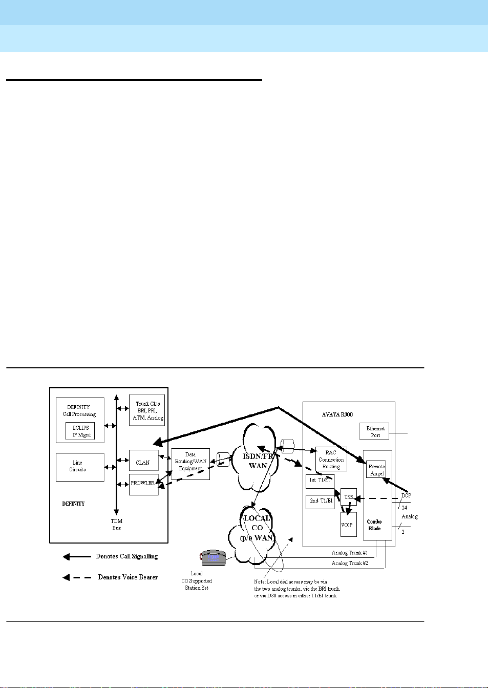
6DEFINITY to remote office signal flow
Figure 3 depicts the detailed signal stream flow of the control messages, voice bearer
channels, and the system management flows between the main DEFINITY site and the
Avaya R300.
Figure 3. Avaya R300 Serving as the WAN Access Concentrator
Page 17

DEFINITY Enterprise Communication Server Release 9
Getting Started with the Avaya R300 Remote Office Communicator
Overview of the Avaya R300 Remote Office Communicator
1
The Avaya R300 can be connected to a WAN using two principle topologies:
■ Direct connection from its WAN ports (T1/E1, BRI, analog trunk) to the WAN
service provider
■ Connection through your existing equipment that serves as the principle WAN
service access point.
The illustration in Figure 3 on page 6 depicts the topology which could be more
commonly u s ed in deploy ments of newly configu re d Remote Offic es. This topology has
the Av aya R300 serving as the principle point of WAN access via its WAN ports. The
A vaya R300 offers the ability to offer both T1/E1 ports, along with two analog trunk ports.
The configuration of available port types will depend on the model of the Avaya R300 unit
(2-T1 or 2-E1 or 6 BRI). The configuration of network resources (what you actually
subscribe to from your WAN service provider) determines what ports on the Avaya R300
are actually used. T1/E1 trunks may be c onfigured in a fraction al mode. The Avaya R300’s
Ethernet port can connect to subtending router(s) if your local LAN configuration is this
size.
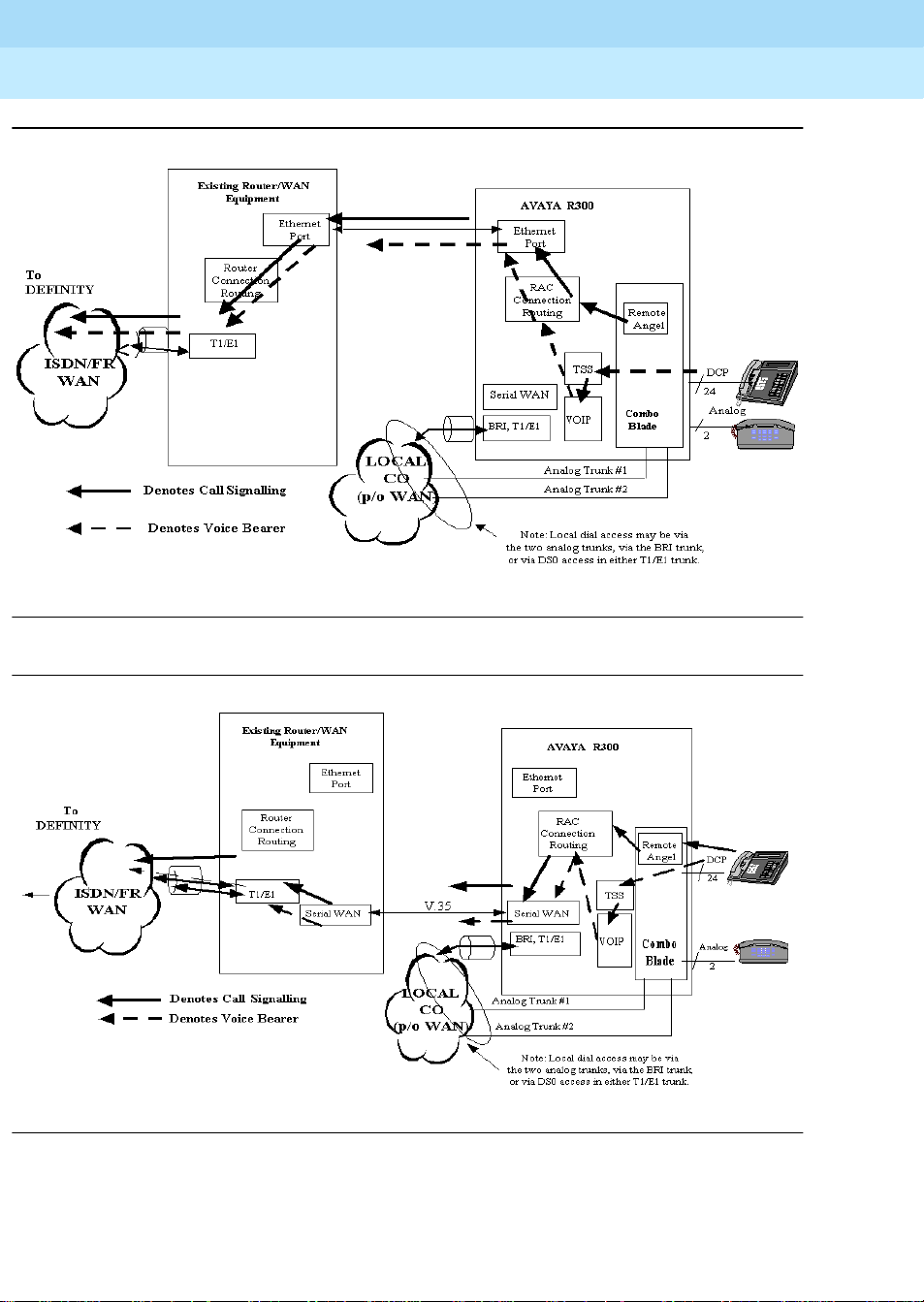
Avaya R300 with existing WAN access equipment
November 2000
Issue 1
7Avaya R300 with existing WAN access equipment
When the Avaya R300 co-exists (subtends) in an office environment with existing WAN
access concentration/routing equipment, two configurations are available:
■ Connection via its Ethernet port over to the local IP LAN (see Figure 4 on page 8)
■ Connection via its Serial WAN port (V .35) over to the Serial inpu t of a WAN router
(see Figure 5 on page 8)
The Avaya R300 offers the ability for DEFINITY call routing to use local access trunks.
These local access trunks may be directly connected to a WAN service provider network,
or the T1/E1 WAN trunks may be subtending to an existing drop and insert T1/E1
connection on the existing WAN access equipment.
The Avaya R300 offers the ability to offer both T1/E1 ports, along with two analog trunk
ports and BRI ports. The configuration of available port types will depend on the whether
the Av aya R300 is a North American or global unit. The configuration of network
resources (what you actually subscribed to from your WAN service provider) determines
what ports on the Avaya R300 are actually used. T1/E1 trunks may be configured in a
fractional mode.
Page 18
DEFINITY Enterprise Communication Server Release 9
Getting Started with the Avaya R300 Remote Office Communicator
Overview of the Avaya R300 Remote Office Communicator
1
November 2000
Issue 1
8Avaya R300 with existing WAN access equipment
Figure 4. Avaya R300 Co-existing with WAN Access Concentrator
Figure 5. Avaya R300 Subtending to Existing WAN Access Concentrator (Serial WAN
Connected to Router)
Page 19
DEFINITY Enterprise Communication Server Release 9
Getting Started with the Avaya R300 Remote Office Communicator
Overview of the Avaya R300 Remote Office Communicator
1
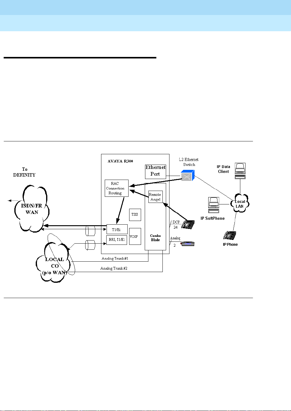
Avaya R300 with local LAN supported IP Softphones and telephones
The Ethernet interface of the Avaya R300 can connect to your LAN with both native
IP-based data clients, as well as native IP-based voice clients. In Release 9, both IP
Softphones (IP voice client application) resident on your PC; or the new Model 46xx IP
telephones will be available.
The IP-based voice and data clients will be connected in a subnet. This subn et is provid ed
by point-to-point serial Ethernet connections to a Level 2 Ethernet switch. The uplink of
this subnet is connected to the Ethernet port on the Avaya R300. It is important that
voice-over-IP clients be connected to switched Ethernet hubs rather than to shared
Ethernet hubs. (See Figure 6 below.)
November 2000
Issue 1
9Avaya R300 with local LAN supported IP Softphones and telephones
Figure 6. Interface Between the Avaya R300 and IP-based Data and Voice Clients
Page 20

DEFINITY Enterprise Communication Server Release 9
Getting Started with the Avaya R300 Remote Office Communicator
Overview of the Avaya R300 Remote Office Communicator
1
Emergency transfer at the DEFINITY Remote Office
The Av aya R300 Emergency Transfer feature provides some limited telephone service in
the case of disaster. This feature enables a relay contact set to directly cut-through the tip
and ring of the two analog station ports and to connect them to the two wire analog trunk
interface. These two analog stations operate in a loop-start trunk mode (for example, go
off-hook to seize an out-going CO trunk connection). See Figure 7 on page 11.
NOTE:
The DCP stations do not operate in this failure mode.
The Emergency Transfer relays operate by:
■ Loss of power on the Avaya R300’s Combo Blade
■ Failure of the Keep-Alive regis tr a tion m e ssage, indicating loss of connectivity
back to a main DEFINITY site.
November 2000
Issue 1
10Emergency transfer at the DEFINITY Remote Office
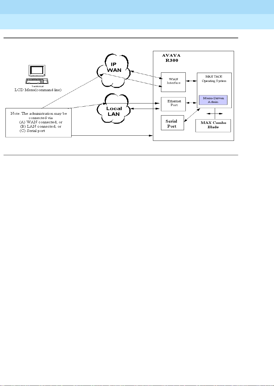
System management for the Remote Office
Avaya R300 Administration
The system management of the Remote Office consists of two functional subsystems:
■ DEFINITY main switch
■ Avaya R300 voice/data switch
The DEFINITY is managed for administration via a SAT interface and/or via the
DEFINITY System Administration (DSA) or DEFINITY Network Administration (DNA)
tools. The Lucent-Ascend Command Line Interface manages the administration of the
A vaya R 300. Within the Avaya R300, the TAOS operating system is designed to support a
menu-driven administration system. This system provides for the full administration of the
Avaya R300 Combo Blade’s voice features. Figure 7 on page 11 shows the current tools
available for configuration management on the Avaya R300.
Page 21
DEFINITY Enterprise Communication Server Release 9
Getting Started with the Avaya R300 Remote Office Communicator
Overview of the Avaya R300 Remote Office Communicator
1
Figure 7. Avaya R300 Administration System
November 2000
Issue 1
11System management for the Remote Office
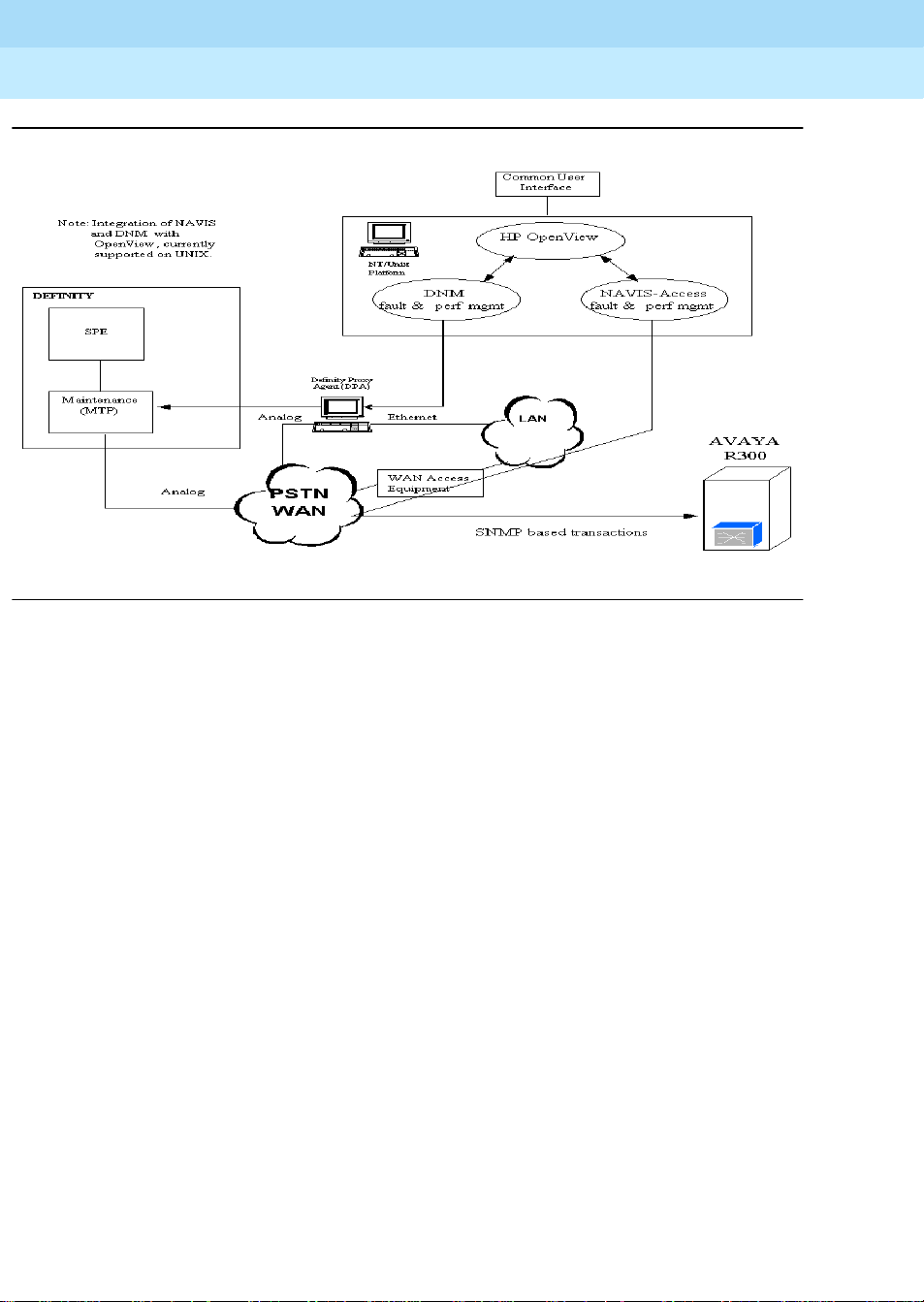
Avaya R300 Fault Management
The NAVIS Access network management tool or a SNMP manager manages the Avaya
R300 for fault and performance. As long as your network connection supports IP-based
communication, the NAVIS system can communicate with the Avaya R300. The NAVIS
Connect system (PC-based) may communicate with the Avaya R300 via a WAN-b ased IP
network, a local LAN, or with a directly connected serial communications port.
The DEFINITY is managed for fault and performance via a SAT interface and/or via the
DEFINITY Network Management (DNM) system. The DEFINITY Network
Management (DNM) product as well as the Lucent-Ascend’s NAVIS Network
Management product operate on the HP OpenView network management application
platform. In fact, they both can concurrently run together under a common platform. See
Figure 8 on page 12.
NAVIS Access is supported on the following platforms:
* Windows NT 4.0
* Solaris 2.5 (Sparc, Intel)
* SunOS 4.1.4
* HPUX 9, HPUX10
* AIX 4.1
* BSD/OS 3.0
* Digital Unix (OSF/1) v4.0
Page 22
DEFINITY Enterprise Communication Server Release 9
Getting Started with the Avaya R300 Remote Office Communicator
Overview of the Avaya R300 Remote Office Communicator
1
November 2000
Issue 1
12System management for the Remote Office
Figure 8. Avaya R300 Fault & Performance Management
Page 23

DEFINITY Enterprise Communication Server Release 9
Getting Started with the Avaya R300 Remote Office Communicator
Avaya R300 Specifications and Network Design
2
Avaya R300 Specifications and
Network Design
What is the Avaya R300?
The Av aya R300 is a small, rack-mountable unit (1.75 in. x 17.5 in. x 17 in.) that features
two expansion slots. The right slot, as you look at the front of the unit, houses a DSP blade
(for Voice over IP option). As you look at the back of the unit, an other slot h ouses the new
Combo Blade. The Combo Blade supports 24 two-wire Digital DCP stations, 2 analog
stations, and 2 analog (600 ohm ) loop start trunks . A single DEFINITY sw itch can support
multiple Avaya R300 units as described in Table 1.
November 2000
Issue 1
13What is the Avaya R300?
2
Table 1. Number of Avaya R300 units supported on DEFINITY platforms
DEFINITY Platform Max # of Avaya R300 units supported
G3r 250
G3si 80
G3csi 80
DEFINITY One 16
IP 600 16
The Av aya R300 and DEFINITY IP Solutions endpoints use common DEFINITY call
processing resources, therefore the number of Avaya R300 units that can be supported is
additive, not mutually exclusive with the number of IP Solutions endpoints supported.
The Avaya R300 provides a cost-effective method for providing the full range of
DEFINITY functionality at a remote site. The remoted telephony has all of the capabilities
of that which is “directly connected” to the DEFINITY switch at the main site. The A vaya
R300 also provides voice and data convergence as voice and data can share the same
WAN link between the DEFINITY and the Remote Office.
Page 24

DEFINITY Enterprise Communication Server Release 9
Getting Started with the Avaya R300 Remote Office Communicator
Avaya R300 Specifications and Network Design
2
Setting up the Avaya R300
The following sections describe requirements and constraints that may affect the setup of
the Av aya R300 Remote Office Communicator.
DEFINITY Requirements
The main DEFINITY system may be a DEFINITY G3r, G3si, G3csi, DEFINITY One, or
IP 600. The main DEFINITY system must use DEFINITY Release 9 (R9) or newer
release software, and the Remote Office option enabled on the System-Parameters
Customer-Options screen. The DEFINITY cabinet housing the connection to the Avaya
R300 may be either a PPN (Processor Port Network) or an EPN (Expansion Port
Network).
In order for you to administer analog/digital stations and analog/digital trunks on the
A vaya R3 00, you must subs cribe to the approp riate Right to Use (RTU) software for these
telephony features members.
November 2000
Issue 1
14Setting up the Avaya R300
Number of ports and Avaya R300 units
Table 2 describes the total number of ports and Avaya R300 units supported by
DEFINITY.
Table 2. Number of ports and Avaya R300 units
Description of Items G3r G3si G3csi
Total stations (max) 5000 1000 400 200 total
Total trunks (max) 4000 400 400 200 total
Total Remote Office Ports supported
in all Remote Offices (administration
limit)
Maximum Number of Avaya R300
units supported
Maximum Number of Network
Regions Supported
DEFINITY
One/IP 600
ports
ports
5000 1000 1000 1000
250 80 80 80
250 80 80 16
Continued on next page
Page 25

DEFINITY Enterprise Communication Server Release 9
Getting Started with the Avaya R300 Remote Office Communicator
Avaya R300 Specifications and Network Design
2
Table 2. Number of ports and Avaya R300 units — Continued
Description of Items G3r G3si G3csi
November 2000
Issue 1
15Setting up the Avaya R300
DEFINITY
One/IP 600
Maximum Number of Locations
44 44 44 1
Supported
TN799C C-LAN: supports up to 442
10 3 2 1
sockets and is an engineered value
(The number of C-LANS supported
for all platforms will increase to an
unspecified quantity.)
TN2302 Media Processor: suppo rts up
25 5 4 1
to 64 simultaneous voice calls and is
an engineered value
The number of TN2302AP IP Media Proces sors req uired is b ased o n the v olum e o f tr af f ic
offered by the active calls on an Avaya R300. The assumption is that one third of the
traffic is carried over the link between the Avaya R300 and the DEFINITY switch, but the
traffic is also based on the percent of calls shuffling. For more information about
shuffling, see ‘‘Shuffling’’ on page 24.
Number of terminals and trunks supported by the Avaya R300
Continued on next page
An individual Avaya R300 supports 26 stations (24 DCP and 2 Analog). For countries
which use 600 ohm impedances, the Avaya R300 also supports two 600 ohm loop-start
CO analog trunks. These two analog trunks support the feature of Emergency Transfer.
This feature enables a relay contact set to directly cut-through the tip and ring of the two
600 ohm analog station ports and to connect them to the two-wire analog trunk interface.
These two analog stations are operating in a loop-start trunk mode (for example, go
off-hook to seize an out-going CO trunk connection). Note that the DCP stations are not
operable in power failure mode. For this feature, the Emergency Transfer relay(s) are
operated either by a loss of power on the Avaya R300 Combo blade or by loss of
registration with the main switch, indicating loss of connectivity back to a main
DEFINITY site. This connectivity loss (could be the main ECS, WAN, LAN) will initiate
an emergency transfer within 60 seconds.
The following are the maximum number of DS0 trunks available:
■ 24 DS0 trunks available per T1 interface with robbed bit signaling (the Avaya
R300 supports a two-T1 model) or 23 with IDSN PRI T1.
■ 30 DS0 trunks per E1 trunk (the Avaya R300 supports a two-E1 model)
■ 2 DS0 trunks in another product model available per BRI trunk (the Avaya R300
supports a six-BRI model).
Page 26

DEFINITY Enterprise Communication Server Release 9
Getting Started with the Avaya R300 Remote Office Communicator
Avaya R300 Specifications and Network Design
2
The total number of DS0 trunks in a given configuration is determined by the number of
each type of trunk.
Types of terminals supported by the Avaya R300
The Av aya R300 can support DCP and analog phones directly and can support IP
Telephones and IP Softphones through its networking component. DCP and analog
phones (and other analog devices) can be connected directly through the Avaya R300
using the Interconnect unit. IP phones must be linked through a data switch or external
routing device from the Avaya R300’s Ethernet port.
The following tables describe the DCP and analog phones supported by the Avaya R300.
Table 3. Supported telephones
2-wire DCP phones
November 2000
Issue 1
16Setting up the Avaya R300
64xx Series:
■ 6402 (non-display)
■ 6402D (display)
■ 6408+ (non-display with
speakerphone)
■ 6408D+ (display with speakerphone)
■ 6416D+ (display with speakerphone)
■ 6416D+M (display, with analog
module)
■ 6424D+ (display with speakerphone)
■ 6424D+M (display with analog
module)
84xx Series:
■ 8403 (non-display with one-way
speakerphone)
Analog phones
■ 6210
■ 6218
■ 8405B (non-display with one-way
speakerphone)
■ 8405D+ (display with two-way
speakerphone)
■ 8410 (non-display with two-way
speakerphone)
■ 8410D (display with two-way
speakerphone)
■ 8411D (display with analog and
asynchronous connectors )
■ 8434DX (display with two-way
speakerphone)
90xx Series:
■ 9031DCP (supports transtalk wireless
base station)
model 2500 sets
■ 6220
Page 27

DEFINITY Enterprise Communication Server Release 9
Getting Started with the Avaya R300 Remote Office Communicator
Avaya R300 Specifications and Network Design
2
Power and physical attributes - Avaya R300
Table 4 describes the dimensions and power attributes of the Avay a R300 unit.
Table 4. Avaya R300 attributes
Attribute Value
Input Power Voltage 100 VAC-240 VAC Universal Input
Input Power Fr equency 50/60 Hz
Input Power 230 W maximum
Fuse 5A/250 V (not user-accessible)
Current 3 A maximum
Weight 17 lbs (7.7 kg)
Height 1.72" (4.37 cm)
Width 17.62" (44.76 cm) (19" rack mount)
November 2000
Issue 1
17Setting up the Avaya R300
Depth 16" ( 40.64 cm)
Avaya R300 Interconnect module
Each A vaya R300 will be supplied with one Avaya R300 Interconnect module which
provides an effective way to interconnect stations and trunks to the Avaya R300. Each
Interconnect module supports 24 DCP stations, 2 analog stations and 2 analog CO trunk
interfaces. Not all connections will be used for each ins tallation an d the CO tr unk s are n ot
supported in some countries.
The Interconnect module also supplies power to the Avaya R300’s Combo Blade to power
the DCP stations. Specifically, the Interconnect module provides 30W of -48VDC which
is used to provide the native “phantom” power for each DCP station (pins 4&5). If the a
Interconnect module is not used, the installation must provide “phantom” power for each
DCP station some other way (for example, 110-interconnect punch down using an Avaya
1145 or equivalent -48VDC power source).
The Avaya R300 Interconnect module provides auxiliary power to pins 7 and 8 for the 24
DCP connections so that a customer can use most auxiliary equipment without need or
concern for local power. This allows customers to use auxiliary equipment such as adjunct
speakerphones, headsets, and additional displays with auxiliary power already available.
Specifically, each DCP connection has a current limited auxiliary power of 6 Watts
(-48VDC). The yellow LED associated with the DCP modular jack will light, indicating a
warning condition, if more than 6 Watts of auxiliary power is drawn (indicating a short).
Page 28

DEFINITY Enterprise Communication Server Release 9
Getting Started with the Avaya R300 Remote Office Communicator
Avaya R300 Specifications and Network Design
2
Power and physical attributes - Avaya R300 Interconnect module
Table 5 describes the dimensions and power attributes of the Interconnect Module.
Table 5. Avaya R300 Interconnect module attributes
Attribute Value
Input Power Voltage 100 VAC-240 VAC Universal Input
Input Power Fr equency 50/60 Hz
Input Power 240 W maximum
Fuse Power supply is fused for protection (not accessible).
Auto-protect for overcurrent, overvoltage on output,
over temperature
Current 3 A maximum
Weight 2 lbs (0.9kg)
Height 1.72" (4.37 cm)
November 2000
Issue 1
18Setting up the Avaya R300
Cabling
Width 17. 62" (44.76 cm)
Depth 8" (20 cm)
The following cabling is required for the Avaya R300:
■ Power cord (appropriate for country of installatio n )
■ DB9-DB9 serial cable
■ 15-ft. (x-m) Y-cable (Comcode #84522991)
— 64/68-pin connector on one end
— DCP (male) amphenol connector on one leg of Y
— analog (female) amphenol connector on other leg of Y
NOTE:
While the cable that comes with the Av aya R300 is fifteen feet long, you can
add additional length to the cable. Additional length should not allow the
distance between the Avaya R300 and the phone to exceed 1000 feet.
■ Serial cable to connect external modem (optional). The control port uses a standard
DB-9 female connector that conforms to the EIA RS-232 standard for serial
interfaces.
Page 29

DEFINITY Enterprise Communication Server Release 9
Getting Started with the Avaya R300 Remote Office Communicator
Avaya R300 Specifications and Network Design
2
The following cabling is required for the Avaya R300 Interconnect module:
■ Power cord (appropriate for country of installatio n )
■ Cable to connect analog and DCP stations to the unit
Additionally, all network cable going to the Avaya R300 should be CAT 5 to provide the
best voice quality poss ible.
For more information about cabling with the Avaya R300, see MAX 3000 Basic
Installation and Configuration Guide, Appendix C, Cables and Connectors.
Wall field cabling
If you prefer to deploy the Avaya R300 with your existing wall field cabling, you can
connect the Combo Blade Y-cable to a conventional wall field panel. The Avaya R300
Combo Blade must be powered with the Y- cable or the Avaya R300 will not function. The
Y-cable has 50-pin, male and female connectors, which allows you to use standard,
Telcom 50-pin cables to extend the reach of the Y-cable to the wall field location. The
analog power plug has a gender changer, which makes the Y-cable compatible with
110-volt hardware.
November 2000
Issue 1
19Setting up the Avaya R300
50-pin male connector on Y-cable
The 50-pin male connector on the Y-cable provides a standard cut-d own conf ig uration fo r
the 24, two-wire sets. For example:
■ DCP-Tip 1 is connected to pin 26
■ DCP-Ring 1 is connected to pin 1
■ DCP-Tip 2 is connected to pin 27
■ DCP-Ring 2 is connected to pin 2
This configuration pattern would continue for up to 24 DCP sets. The auxiliary power for
the DCP sets is delivered on pins 7 & 8 of each set. Pin 7 is -48Vdc lead and pin 8 is
ground (+48Vdc) lead.
The maximum power level for each DCP s et is 6 watts or a 120-watt maximum of 48Vdc .
The voltage range for operation must be greater than 42.5Vdc and less than 56.5Vdc. The
current limit for each DCP set is 170Ma.
Page 30

DEFINITY Enterprise Communication Server Release 9
Getting Started with the Avaya R300 Remote Office Communicator
Avaya R300 Specifications and Network Design
2
50-pin female connector on Y-cable
The 50-pin female connector on the Y-cable provides the co mmun ic atio n flo w fo r the two
analog stations and two analog loop st art trunks, and prov ides the source of - 48 volts to the
Combo Blade (for phantom power of DCP sets).
When using analog sets, make the following pin connections:
1. Analog line-Tip 1 is connected to pin 26
2. Analog line-Ring 1 is connected to pin 1
3. Analog line-Tip 2 is connected to pin 30
4. Analog line-Ring 2 is connected to pin 5
5. Analog trunk-Tip 1 is connected to pin 42
6. Analog trunk-Ring 1 is connected to pin 17
7. Analog trunk-Tip 2 is connected to pin 46
8. Analog trunk-Ring 2 is connected to pin 21
November 2000
Issue 1
20Setting up the Avaya R300
The analog and power female connector on the Y-cable supplies 30 watts of -48Vdc to the
Combo Blade (25 watts under load condition). The battery (-48Vdc) is connected to pins 9
& 13 while the ground (+48Vdc) is supplied on pins 34 & 38. You should provide both
pairs of signals to maintain an appropriate impedance for the source to the -48 volts.
The voltage range for operation must be greater than 42.5Vdc and less than 56.5Vdc. The
current must be limited to 750ma.
NOTE:
Power units must have safety and emission appro vals app ropriate for the co untr y o f
installation. The power applied to the Combo Blade may require FCC part 68
registration or other country telco registration.
NOTE:
Power supplied to the Avaya R300 Combo Blade must meet the following
standards:
■ Power Required: 48Vdc at 150W with a minimum of 42.5Vdc and a
maximum of 56.5Vdc
■ Current Limit: Phantom Power 750Ma, Auxiliary Power 170Ma per DCP
set
■ Line and Load Regulation: p l us or minus 2%
■ Minimum Load: 0 Watts must regulate at no load
■ Protection: Overvoltage, Overcurrent
Page 31

DEFINITY Enterprise Communication Server Release 9
Getting Started with the Avaya R300 Remote Office Communicator
Avaya R300 Specifications and Network Design
2
Bandwidth engineering considerations
The bandwidth available for communication between the main DEFINITY ECS host and
the Avaya R300 is dependent on several factors. The following gives a high level
overview of the items for consideration. The Remote Office has three principle forms of
traffic back to the host site (See Figure 9):
■ Voice bearer traffic (carried on IP streams, over WAN network channels)
■ H.323V2 call signaling/registration traffic (carried on IP streams, over WAN
network channels) and tunneled maintenance
■ IP routed data network traffic (carried on PPP streams, over WAN network
channels)
Host
Definity
Call Processing
DOLAN
IP Mgmt
Line
Circuits
DEFINITY
Trunk Ckts
BRI, PRI,
ATM, Analog
CLAN
PROWLER
(VOIP
Resources)
TDM
Bus
Denotes Data Bearer
Denotes Call Signalling
Denotes Voice Bearer
LAN
Data
Routing
& WAN
Equipment
(Could be
UNM)
ISDN/FR
WAN
LOCAL
CO
(p/o WAN)
November 2000
LOCAL
DEFINITY Remote MAX
Ether
RAC
Connection
Routing
1st T1/E1
2nd T1/E1
Analog Trunk #1
Analog Trunk
Denotes Data Bearer Resources
Denotes Voice Bearer Resources
Remote
Angel
TSS DCP
Combo
VOI
Blade
P
#2
Issue 1
21Bandwidth engineering considerations
LAN
24
Analog
2
Figure 9. Bandwidth engineering for the Avaya R300
Page 32

DEFINITY Enterprise Communication Server Release 9
Getting Started with the Avaya R300 Remote Office Communicator
Avaya R300 Specifications and Network Design
2
Network Components
The bandwidth traffic engineering depends on several components of the distributed
network:
■ IP Media Processors
■ Host-side WAN or LAN access/routing equipment
■ WAN Network Services Subscription
■ Avaya R300 WAN Access Trunks
■ Multi-Voice DSP R esources in the Avaya R300
IP Media Processor
In DEFINITY, the IP Media Processor (TN2302AP) supports audio conferencing and
bearer conversion (from TDM based traffic to IP based traffic). To provide bearer
conversion, this circuit pack supports voice processing algorithms that are housed in a
DSP farm. This DSP farm currently is designed to support 32 channels of G.729
(compressed 8 Kbps encoding) and/or G.723 (compressed 5.3 Kbps) or 64 channels of
G.711 (64 Kbps encoding) for voice bearer traffic. Although the TN2302AP supports
G.723, this encoding scheme is not applicable to the Avaya R300. To scale to various
switch processing needs, multiple IP Media Processors can be supplied in a switch
configuration.
November 2000
Issue 1
22Bandwidth engineering considerations
The choice of CODECs used for voice is under the supervision of the DEFINITY call
processing. To conserve on bandwidth for WAN network services, use a compression
algorithm.
Host-side WAN access and routing equipment
The WAN access equipment (access concentrator and rou ter) su ppo rt a var iety o f n etwork
interfaces and a certain capacity. For example, there may be multiple T1/E1 interfaces
available. With each physical interface, individual “pipes” may be used (these are most
commonly DS0-based (64Kbps). These pipes may use bonding to aggregate multiple DS0
components into a larger pipe.
For the WAN access equipment, there must be a negotiated service agreement between the
customer and the enterprise/public network provider.
NOTE:
IP- based streams must always traverse some kind of physical channel.
WAN network services subscription
The supporting network is arranged/subscribed in terms of a negotiated network service
between you and your service provider. This service is a function of the:
■ service type such as fractional T1/E1, full T1/E1, frame relay, etc.
■ number of network interfaces (for example, multiple T1/E1)
Page 33

DEFINITY Enterprise Communication Server Release 9
Getting Started with the Avaya R300 Remote Office Communicator
Avaya R300 Specifications and Network Design
2
Remote Office WAN access trunks
The Avaya R300 offers a variety of WAN interfaces. The North American model offers
two T1 interfaces. The Global model offers two E1 interface interfaces. These interfaces
are referred to as “digital trunks”. These interf aces may be used fo r network control/bear er
communication to the host switch site, or local access trunks (to the local network central
office).
Since the traffic within T1/E1 trunks is actually a group of individually switched DS0
(64Kbps) pipes, traffic within these T1/E1 facilities can be directed to two or more
destinations. Therefore, both local trunk access traffic and traffic destined for the main
switch host site may use a given Avaya R300 WAN trunk facility.
In Release 1.1 of the Avaya R300, you have access to the two analog loop-start trunks to
provide additional bandwidt h (two DS0' s). You can use this added bandwidth for stan dard
operational PSTN trunk bandwidth.
MultiVoice DSP resources in the Avaya R300
In the Avaya R300, the bearer conversion (from TDM based traffic to IP based traffic) is
performed in a Multi-Voice DSP module. The DSP-16 module, which supports 16
channels of TDM voice to IP voice conversion, is now available. The DSP-30 module,
which supports 30 channels of TDM voice to IP voice conversion, will be available in the
near future.
November 2000
Issue 1
23Bandwidth engineering considerations
The Connection Management software module in the Avaya R300 determines if both
parties are connected via local ports (either local access trunks or DCP/analog station sets)
on the Avaya R300 unit. If both parties are local, the switch connection will be offered
over a TDM based connection with that Avaya R300. Otherwise, a VOIP channel is
utilized for each party that is connected.
Engineering bandwidth components
The five networking components must be engineered appropriately. A general equation
might be: Total Bandwidth = (Aggregate voice bandwidth) + (Aggregate data bandwidth).
■ Aggregate Voice Bandwidth = (Aggregate Voice Bearer bandwidth) + (Aggregate
signaling bandwidth associated with these voice applications)
■ Aggr egate data bandwidth is that ban dwidth devoted for IP traffic bet ween host
and remote sites.
Aggregate voice bearer bandwidth is a function of the call traffic model. You would take
the amount of equipped stations (DCP, analog), together with the amount of equipped
local access trunks), and calculate the amount of average traffic that is networked back to
the DEFINITY host site. A typical configuration could have as many as half of the calls be
networked back to the DEFINITY. In this example, you would multiply the number of
endpoints by the CODEC used, to determine needed bandwidth.
NOTE:
The bandwidth for call signaling and registration traffic is estimated to be two DS0's
in size for a full deploy ment of 24 digital stati ons, 2 analog stations, and a full
complement of trunk group members.
Page 34

DEFINITY Enterprise Communication Server Release 9
Getting Started with the Avaya R300 Remote Office Communicator
Avaya R300 Specifications and Network Design
2
Shuffling
Shuffling refers to an IP endpoint’s ability to redirect its IP audio stream in the middle of a
call. This feature is new for DEFINITY Release 9. Most endpoints made by other
companies are not capable of this feature. Shuffling reduces the resources required to
switch audio calls, and eliminates the need to involve the Media Processor directly in an
IP network ed call.
Prior to Release 9, all audio streams were set up between an endpoint and a Media
Processor board on DEFINITY. If one IP endpoint called another, the IP audio was routed
to a Media Processor board, converted to TDM audio, routed back to a Media Processor
board, converted back to IP audio, and finally routed t o the other IP endpoint.
This IP-TDM-IP model made things easi er fo r t he IP endpoints, but had drawbacks. Fir st,
the call between 2 IP endpoints used resources on the Media Processor board and
DEFINITY backplane, even though the audio was simply looping back out to the IP
network. The second drawback was that the audio quality suffered due to the unneeded
conversion from IP audio to TDM audio and back again to IP audio. Finally, the distance
of the IP routed call was unnecessarily long, causing increased network delays. For these
reasons, it is preferable to set up the IP audio connection directly between two IP
endpoints. For this to happen, however, the DEFINITY processor must have R9 software
and both IP endpoints must be capable of shuffling.
November 2000
Issue 1
24Bandwidth engineering considerations
If the Avaya R300 is incapable of shuffling, or if the DEFINITY switch is not
administered to allow shuffling, all calls route through the Media Processor board on the
DEFINITY. This applies even to calls from one Avaya R300 station to another, or from an
A v aya R 300 station to an Avaya R300 trunk. Thus, calls would use additional DEFINITY
resources and exhibit poor audio quality due to the IP-TDM-IP conversion. The calls
would also utilize unnecessary DSP resources in the Avaya R300, and these DSP
resources are a valuable resource that could easily become exhausted if all calls were
utilizing them. The audio quality could also decrease for Avaya R300 endpoints because
the audio packets would be making, in most cases, two trips across the WAN link. Since
all remote calls would be unnecessarily routed across the toll network back to the
DEFINITY, costs for WAN service would increase.
To implement shuffling on the Avaya R300, administer the DEFINITY to shuffle all
Avaya R300 stations and signaling groups. Specifically, enable the Direct IP-IP Audio
Connections option on the following DEFINITY administration screens:
■ Globally, on the Feature-Related System Parameters screen
■ On the IP Network Region screen that corresponds with the Avaya R300’s network
region
■ For each station on the Station screen (page 2)
■ On the Signaling Group screen (only if using trunks on the Avaya R300)
Page 35

DEFINITY Enterprise Communication Server Release 9
Getting Started with the Avaya R300 Remote Office Communicator
Avaya R300 Specifications and Network Design
2
C-LAN resources at DEFINITY ECS
Each station set will require one active TCP/IP control link for as long as the set is both
physically connected and the station is administered to “TTI” or “named” on the Avaya
R300 unit. Each trunk (digital or analog) will have a TCP/IP control link established for
the duration of an active call. A control link will consume one socket in the C-LAN board,
which has up to 442 sockets available for use.
The DEFINITY needs a number of C-LAN circuit packs greater than or equal to the total
socket usage divided by 442 and then rounded up.
IP Media Processor resources
In DEFINITY, the IP Media Processor supports audio conferencing and bearer
TDM-based traffic to IP-based traffic. In order to provide bearer conversion, this module
supports voice processing algorithms through DSPs designed to support 64 resources:
subtract one resource per G.711 call, subtract two resources per G.729 call.
November 2000
Issue 1
25Bandwidth engineering considerations
DSP resources
The DSP farm on the Avaya R300 converts calls from TDM to IP for voice/fax traffic
through the Avaya R300 across an IP network to DEFINITY or to another Avaya R300.
The DSP-16 card is available now; the DSP-30 card will be available in the near future.
The DSP farm can convert, at most, 30 voice streams between IP and PCM-TDM.
Conversions are not required between two voice (analog or DCP) endpoints within the
same A vaya R3 00 or between these vo ice stations and incomin g or outgoing calls on local
trunks connected to the Avaya R300.
LAN/WAN access/routing equipment
The supporting network is arranged in terms of a negotiated network service between the
customer and the service provider. This service is a function both of service type (for
example, fractional T1/E1, full T1/E1, frame relay) and the number of network interfaces
(for example, multiple T1/E1). The network requirements for any DEFINITY IP Solutions
customer is found in the DEFINITY IP Solutions Voice Quality Network Requirements or
on the web at www.avaya.com.
Page 36

DEFINITY Enterprise Communication Server Release 9
Getting Started with the Avaya R300 Remote Office Communicator
Avaya R300 Specifications and Network Design
2
Network region design
The A vaya R300 can receive data fr om a T1, E1 or BRI line (depending on the mo del) and
pass information through PSTN trunks, through drop/insert trunks (on the T1 model,
only), and through the Ethernet to a LAN/WAN.
The switch administrator can assign the Avaya R300 within a Network Region in the same
manner as other DEFINITY IP resources such as a Media Processor are assigned to a
Network Re gion. DEFINITY permits the administrator to specify, by region, an ordered
set of CODECs to be used for connecting endpoints within the region and a set to be used
to interconnect an endpoint in the region to an endpoint in another region. Separate A vaya
R300 units within the same office, or in different offices that are close through an IP
network, ma y be assigne d the same network region in order t o share the same type of
interconnectivity. Endpoints in different regions may be assigned with limited or no
interconnectivity.
The use of network regions can insure that intra-region office connections use a
high-quality CODEC with low delay while inter-region office connections use a
low-bandwidth CODEC to conserve network resources. However, it is reasonable to
configure multiple Avaya R300 endpoints into the same region if they share sufficient
network interconnectivity among themselves.
November 2000
Issue 1
26Network region design
The Avaya R300 supports the following IP audio CODECs:
■ G.729
■ G.729 Annex A
■ G.729 Annex B
■ G.729 Annex A/Annex B
■ G.711 A- law 64k
■ G.711 A- law 56k
■ G.711 u-law 64k
■ G.711 u-law 56k
The Avaya R300 always advertises CODECs to DEFINITY at registration time in the
order shown above. The order of the CODECs that the Avaya R300 advertises to
DEFINITY at registration time is more important in determining wh ich C ODEC is
selected for a call than the order of the CODECs in the CODEC set on the DEFINITY.
DEFINITY will always attempt to utilize a CODEC at or near the top of an endpoint’s
capability set, even if that CODEC is low in the CODEC set on DEFINITY.
For example, suppose a CODEC set on DEFINITY consists of G.7111 Mu-law 64K,
followed by G.729, and G.723.1. DEFINITY would select G.729 for the CODEC on a call
involving an Avaya R300 endpoint since G.729 is at the top of the Avaya R300’s
capability set. In fact, the only way to force DEFINITY to select one of the other CODECs
over G.729 is to have a CODEC set that does not include G.729 at all.
Page 37

DEFINITY Enterprise Communication Server Release 9
Getting Started with the Avaya R300 Remote Office Communicator
Avaya R300 Specifications and Network Design
2
G.729 is at the top of the Avaya R300’s capability set because it is a low bit-rate CODEC.
Since most Av aya R300s will be across the WAN from their host DEFINITY, it is
desirable to use a low bit rate CODEC like G.729 (8k), as opposed to G.711 (64k) to
conserve WAN bandwidth.
Possibly, a site cou ld have two Avaya R300s present at the same location. In this case, you
might prefer to use G.729 for all calls between the host DEFINITY and the Avaya R300s,
but use G.711 b etween the two Avaya R300s. The reasoning is that it would be good to us e
G.729 across the WAN (which has reduced bandwidth). This can be accomplished using
multiple network regions and multiple CODEC sets.
When administering the DEFINITY, the administrator would place the Media Processor
boards in network region 1, and place both the Avaya R300s in network region 2. The
administration would then create two CODEC sets. One of the CODEC sets (CODEC set
1) would contain G.729. The ot her CO DEC s et (CO DEC set 2 ) wo uld contain only G .711.
The administrator would then specify that CODEC set 1 was to be used between network
regions 1 and 2, and CODEC set 2 was to be us ed within net work region 2.
If you do not identify network regions for the Avaya R300 endpoints, the switch will use
the default network region for the C-LAN board that the Avaya R300 has registered to.
The network region assigned to the Avaya R300 determines what C-LAN board calls will
route through. The proper use of network regions will improve the quality of service to the
Avaya R300 and the stations supported by the unit.
November 2000
Issue 1
27Network region design
The network region assigned to an Avaya R300 is the network region assigned to all
stations supported by that Avaya R300.
You can use network regions to control interconnection of endpoints within a remote
office or between a remote office and the main switch or other remote offices. You can
also use network regions to define administ rative considerations, in particular, Quality of
Service definitions. If different Quality of Service values are used in different parts of the
network, those parts should be defi ned as different regions. Use region-based CODEC
selection algorithms and region-based interconnectivity ru les when interconnecting
IP-based endpoints.
Page 38

DEFINITY Enterprise Communication Server Release 9
Getting Started with the Avaya R300 Remote Office Communicator
Avaya R300 Specifications and Network Design
2
911 Emergency Assistance calls
The Avaya R300 serves to transparently extend the DEFINITY capabilities to a remote
location. The effect of this is that the endp oints connected to the Avaya R300 function as if
they were directly connected to the DEFINITY. The endpoints share the same dial plan
and have access to the full complement of functionality provided by the DEFINITY.
While feature and access-transparency are fundamental attributes of this solution, they
also interfere with accurate delivery of 911 calls.
Development of an E911 strategy for the Avaya R300 ensures that emergency assistance
calls are routed to the appropriate PSAP. The absence of a Avaya R300 911 strategy would
potentially result in 911 emergency assistance calls from Avaya R300 endpoints being
routed to the Public Safety Answering Point (PSAP) assigned to the main DEFINITY. The
calls should be routed to the PSAP designated to field emergency calls originating from
the Av aya R300 location. The Avaya R300 911 strategy has two requirements:
■ 911 calls originating from stations connected to an Avaya R300 must be
selectively routed to the PSAP servicing the Avaya R300 location, and not to the
PSAP servicing the controlling DEFINITY.
November 2000
Issue 1
28911 Emergency Assistance calls
■ Avaya R300 911 calls must be accompanied by correct automatic number
identification (ANI) or caller ID information.
The Avaya R300 911 strategy takes advantage of the ability to associate a location
designation with each Avaya R300. Each DEFINITY system has the capacity to support
up to 44 locations. Accordingly, each DEFINITY provides the ability to accurate route
911 emergency access request calls to these locations. It is possible to support more than
44 Avaya 300s using this strategy if multiple units are associated to a single location. In
cases where one DEFINITY is to support more than 44 Avaya R300 units, and these units
do not map to 44 locations, this strategy must be augmented.
If a maximum of 44 locations is insufficient to accommodate a complex Remote Office
configuration, accurate 911 call routing can be achieved using ARS Partitioning in
conjunction with locations. This allows up to eight different routing options per location.
Although the DEFINITY administration to accomplish this is fairly co mplex, this strategy
provides sufficient routing alternatives to support the maximum number (250) of Avaya
R300 units that can be maintained by a single DEFINITY.
The following diagram is an example of a DEFINITY Remote Office configuration with
two Avaya R300 units connected via a LAN or T1 interface to a central controlling
DEFINITY. One Avaya R300 is located in Holmdel, New Jersey, and the other is located
in Denver, Colorado. The controlling DEFINITY is located in Chicago, Illinois. Consider
the following diagram as a portion of a Remote Office configuration that exceeds 44
locations, and therefore requires the use of ARS Partitioning to support accurate delivery
of 911 calls.
Page 39

DEFINITY Enterprise Communication Server Release 9
Getting Started with the Avaya R300 Remote Office Communicator
Avaya R300 Specifications and Network Design
2
November 2000
Issue 1
29911 Emergency Assistance calls
Figure 10. Remote office configuration for 911 strategy
Page 40

DEFINITY Enterprise Communication Server Release 9
Getting Started with the Avaya R300 Remote Office Communicator
Avaya R300 Specifications and Network Design
2
November 2000
Issue 1
30911 Emergency Assistance calls
Page 41

DEFINITY Enterprise Communication Server Release 9
Getting Started with the Avaya R300 Remote Office Communicator
Avaya R300 Installation and Upgrade
3
Avaya R300 Installation and Upgrade
Installing the Avaya R300
The Avaya R300, a part of the Remote Office Solutions, allows you to support all the
functionality available on your DEFINITY system from a remote location. The Avaya
R300 is a combination switch and power supply that, along with an R300 Interconnect,
connects your remote office to the main DEFINITY through a Wide Area Network
(WAN) connection.
November 2000
Issue 1
31Installing the Avaya R300
3
General Instructions
■ Follow all caution and warning labels and instructions marked on the equipment or
included in these installation instructions.
■ Installation and maintenance of the R300 Communicator and Interconnect units
must be performed by service p ersonnel. There are no user serviceab le parts insi de
either the Communicator or Interconnect units.
■ The maximum recommended operating ambient temperature for this equipment is
°C (104°F). Allow sufficient air circulation or space between units when
40
installing this product in a closed rack assembly. To ensure reliable operation and
prevent overheating, the ventilation openings in the units must not be blocked or
covered.
■ If the equipment is to be mounted in a rack or cabinet that is not securely fastened
in place, consideration must be given to avoid hazards due to uneven loading
(overbalancing).
■ For products install ed in Nord ic countries (except Central Office equipment), a
type B plug or permanent connection must be used for connections to the main
power supply.
■ All intra-building communication wiring associated with the R300 system must be
26 AWG (0.13mm2) or larger.
Page 42

DEFINITY Enterprise Communication Server Release 9
Getting Started with the Avaya R300 Remote Office Communicator
Avaya R300 Installation and Upgrade
3
AC Power and Ground
!
WARNING:
This equipment must only be installed and maintained by service personnel.
!
CAUTION:
Proper AC pow er and ground wiring is critical for proper and safe operation of this
product and must be verified by trained service personnel. Any problems associated
with this wiring must be corrected by a qualified electrician. Pr otective earthing The
AC power circuit must be dedica ted to the syst em and must not be sh ared with other
equipment and must not be contro lled by a wall switch. The AC receptacle should
not be located under the MDF.
!
CAUTION:
The AC power circuit must be dedicated to the system and must not be shared with
other equipment and must not be controlled by a wall switch. The AC receptacle
should not be located under the MDF.
November 2000
Issue 1
32Installing the Avaya R300
!
CAUTION:
System grounding must comply with the general rules for grounding contained in
Article 250 of the National Electrical Code (NEC), National Fire Pr otection Agency
(NFPA) 70, or the applicable electric code in the country containing the equipment.
!
CAUTION:
The R300 Communicator and Interconnect units contain auto-ranging power
supplies (100 – 240 Vac, 50 – 60 Hz) and require 3 amps maximum current a piece.
The AC power source can be 1 phase of 120 Vac with neutral (100 Vac for Japan)
with a 15 amp circuit breaker , or 1 phase of 220 or 240 V ac (200 Vac for Japan) with
a 10 amp circuit breaker. A single, dedicated AC branch can service both the R300
Communicator and Interconnect units. These units require a three-wire AC cord
having eit her a NEMA 5- 15P plug or an IEC 320 plug.
!
CAUTION:
To remove AC power from either the Communicator or Interconnect units, pull the
AC power cord from the AC appliance coupler on the rear of the unit. Even when
AC power is removed from the Communicator unit, the Communicator may still be
receiving –48Vdc from the Interconnect unit. To remove all power from the
Communicator, either th e Interconnect unit AC power cord or the interconnection
cable between the Communicator and the Interconnect unit must be disconnected.
Page 43

DEFINITY Enterprise Communication Server Release 9
Getting Started with the Avaya R300 Remote Office Communicator
Avaya R300 Installation and Upgrade
3
Required equipment and information
On the main DEFINITY PPN or EPN (DEFINITY ECS r, si, or csi platform, DEFINITY
ONE, or IP 600):
■ Release 9 or later software
■ TN799C Control-LAN (C-LAN) circuit pack in a DEFI NITY system fo r firm ware
download (A TN799B will work as long as one C-LAN circuit p ack is a TN7 99C.)
■ TN2302AP IP Media Processor circuit pack
■ Router/Access concentrator to serve as IP gateway
■ IP address for C-LAN circuit pack
■ IP address for IP Media Processor
■ WAN Router (with Network Services)
At the remote site:
■ Avaya R300 (and associated cables)
■ Interconnect module (and associated cables)
November 2000
Issue 1
33Installing the Avaya R300
■ Mounting rack (optional)
■ Terminal/ PC for administering the Avaya R300
■ IP Network Tap (valid IP address and subnet mask which is customer supplied)
■ U.S. Robotics 9.6 K modem or the equivalent (for remote maintenance)
Required tools
■ #2 cross (Phillips) scr ewdriver for the Avaya R300
— Terminal communications software (such as Microsoft HyperTerminal)
— Optionally, a telnet ses sion from an IP terminal
— TFTP server software (required only for R300 firmware upgrades)
— FTP server software
— directory to store files
NOTE:
At least one modem is required for maintenance. If there are two Avaya
R300 units, then two modems should be supplied in case one of the modem
links is faulty. For additional Avaya R300 units, telnet may be enabled
between Av aya R300 units with a modem, or additional modems are
required for each additional Avaya R300 unit.
■ #2 cross (Phillips) scr e wdriver for R300 Interconnect module
Page 44

DEFINITY Enterprise Communication Server Release 9
Getting Started with the Avaya R300 Remote Office Communicator
Avaya R300 Installation and Upgrade
3
Installation process
The following steps describe the process for installing the hardware into a rack:
■ Unpack and inspect equipment
■ Mount the Avaya R300
■ Mount the R300 Interconnect module
■ Interconnect the Avaya R300 and Interconnect module
■ Connect DCP and analog telephones, Ethernet, T1 lines, to the Avaya R300 and
R300 Interconnect module
■ Administer on DEFINITY system
■ Administer on the Avaya R300
Unpack and inspect equipment
Check the order and the packing lists to confirm that th e following equipment is present. I f
any equipment is missing, report this to your Avaya representative.
November 2000
Issue 1
34Installing the Avaya R300
The Avaya R300 package:
■ Power cord (ensure the cord is correct for the country of installation)
■ DB9-DB9 serial cable
■ 15-ft (x-m) Y cable (Comcode #84522991)
■ 25-to-9 pin adapt er
■ Mounting brackets
■ Avaya R300
— combo blade - preinstalled and preconfigured for the Avaya R300
— DSP30 or DSP16 card - preinstalled and p recon figur ed fo r the Avaya R300
■ MAX 3000 Installation and Bas ic Co nfiguration Guide book
■ Getting Started with the Avaya R300 Remote Office book (this book)
■ Avaya DEFINITY Release 9 documentation CD
The Av aya R300 Interconnect module:
■ Power cord (ensure the cord is correct for the country of installation)
■ Mounting brackets (come installed)
■ Avaya R300 Interconnect module
■ Rubber Feet (packed in plastic)
Page 45

DEFINITY Enterprise Communication Server Release 9
Getting Started with the Avaya R300 Remote Office Communicator
Avaya R300 Installation and Upgrade
3
Off-Premises Circuit Protection
Protection from hazardous voltages and currents is required for all off-premises
(out-of-building) trunks. Both over-voltage (lightning, power induction, and so forth) and
sneak current protection are required. Sneak current protectors must be either UL listed /
CSA certified, or must comply with local safety standards.
Sneak current protectors must have a maximum rating of 350mA, and a minimum voltag e
rating of 600V. The following devices protect the system from over-voltages:
■ Analog trunks use the 507B or SCP-110 sneak current protectors. Over-voltage
protection is normally provided by the local telephone company.
■ T1 / E1 / DS1 circuits require isolation from exposed facilities. Thi s insulation
must be provided external to the T1 / E1 / DS1 circuit pack, and be must be
equipment agency-approved for this application. A CSU (T1), LIU (E1), or other
equipment that provides equivalent protection, is assumed.
The DCP voice terminals and analog voice terminals used with the R300 system are
restricted to on-premise use only, and do not require sneak current protection.
November 2000
Issue 1
35Installing the Avaya R300
Install Sneak Fuse Panels
Sneak current protection is required between the incoming RJ21X or RJ2GX network
interface and the system for both trunk and off-premises circuit packs.
The model 507B sneak current fuse panel or 110-SCP-9 sneak current protectors shall be
used. The panel contains two 25-pair connectors, fuse removal tool, and fifty 220029
Sneak Fuses (and two spares).
Table 6. Sneak Fuse Panel Ordering Information
Description Comcode
157B Connecting Block 403613003
SCP-110 Protector 406948976
507B Sneak Current Fuse Panel 107435091
220029 Sneak Current Fuse 407216316
NOTE:
The 507B includes 52 sneak fuses and 2 cables and can be ordered using PEC code
63210. The SCP-110 protectors are used with 110-type hardware and on the 507B
Sneak Fuse Panel. The SCP-110 Protectors can be ordered separately and installed
on the 157B connecting block. Fifty protectors are required per block.
Install the 507B near the network interface or MDF with locally-obtained #12 ¾-inch
screws (or equivalent).
Page 46

DEFINITY Enterprise Communication Server Release 9
Getting Started with the Avaya R300 Remote Office Communicator
Avaya R300 Installation and Upgrade
3
Mount Avaya R300
Refer to the MAX 3000 Installation and Basic Configuration Guide, Chapter 2: “Setting
Up and Testing the MAX Hardware,” for information on mounting the Avaya R300 in a
19" rack.
!
CAUTION:
Do not plug in the Avaya R300’s power cord until all other connections have
been made.
Mount Avaya R300 Interconnect module
NOTE:
If not using a mounting rack, place the R300 Interconnect module on top of the
A vay a R300 with the backs aligned.
If mounting in the same rack as the Avaya R300, mount the Interconnect module above
the Av aya R300 with the backs aligned (see Figure 11).
November 2000
Issue 1
36Installing the Avaya R300
Port 1
DCP IN
ANALOG/
CO/
POWER
TX
LNK DPLX
SEE MANUAL
CAUTION
COL 100BT
RX
LAN UTP WAN 1 WAN 2 WAN 3 CONTROL SERIAL
R300
INTERCONNECT
POWER
ON
Port 13
Port 12
Port 24
rcdfmax1 LJK 103100
Figure 11. R300 Interconnect module and Avaya R300 mounted in rack
1. Attach the mounting brackets to the unit using the screws provided.
2. Secure the unit to the rack, leaving about 2 in. ( 5 cm) of space between th e unit and
the A vaya R300.
DCP
1-12
DCP
13-24
CO
TRUNK
1-2
ANALOG
STATION
1-2
Page 47

DEFINITY Enterprise Communication Server Release 9
Getting Started with the Avaya R300 Remote Office Communicator
Avaya R300 Installation and Upgrade
3
Wall-Mount the Interconnect unit:
The plywood and the hardware to mount the plywood are installer-provided.
1. Secure a ¾ inch (2 cm.) thick sheet of 24” (61 cm.) x 4” (10 cm.) plywood to the
wall using screws. At least one s ide of the plywoo d shou ld be secured to a framing
timber (i.e., 2 x 4) in the wall.
2. Secure the Interconnect unit to the plywood using the screws included with the
Interconnect unit.
Connect the Avaya R300 and R300 Interconnect module
On the Avay a R300:
1. Slide the ejector on the Combo Blade as far to the right as possible, then gently
slide the ejector back to the left. The ejector moves about 1/8” to the left and locks
(stops) to reveal connector pins. The ejector is now correctly positioned so you can
insert the 68-pin connector. (see Figure 12).
November 2000
Issue 1
37Installing the Avaya R300
TX
LNK DPLX
SEE MANUAL
CAUTION
COL 100BT
RX
LAN UTP WAN 1 WAN 2 WAN 3 CONTROL SERIAL
.75”
(19 mm)
prdfmax LJK 103100
Figure 12. Ejector lock in connector insertion position
Page 48

DEFINITY Enterprise Communication Server Release 9
Getting Started with the Avaya R300 Remote Office Communicator
Avaya R300 Installation and Upgrade
3
2. Place the top of the 68-pin connector at a 45-degree angle to the far right side of
the pins (see Figure 13).
November 2000
Issue 1
38Installing the Avaya R300
Figure 13. Connector at proper angle (45 degrees) for insertion
3. Move the connector so it is parallel to the pins.
4. Firmly push the connector in until it clicks into place.
!
CAUTION:
Do not force the connector into place if it isn’t aligned properly. If you force
the connector, you can bend the pins. Also be sure the connector is not
installed upside down. This is possible.
prdfmax2 LJK103100
Page 49

DEFINITY Enterprise Communication Server Release 9
Getting Started with the Avaya R300 Remote Office Communicator
Avaya R300 Installation and Upgrade
3
5. Plug in one end of the power plug.
!
CAUTION:
Do not plug into any electrical outlet until everything is connected.
On the Avay a R300 Interconne ct modu le:
1. Loosen the Velcro security strap over the socket and plug.
2. Plug in the DCP (male) Amphenol connector into the top socket.
3. Plug in the analog (female) Amphenol connector into the bottom plug.
4. Tighten the Velcro strap and lock it in place.
5. Plug in one end of the power plug.
!
CAUTION:
Do not plug into wall outlet until everything is connected.
November 2000
Issue 1
39Installing the Avaya R300
Complete connections
Refer to Figure 14 for port and connection descriptions for the Avaya R300 and R300
Interconnect module and Figu re 15 fo r connectio n diagram fo r the Avaya R300 and R300
Interconnect module.
1. Plug in the Ethernet connection (D8W).
2. Plug in the T1, E1, or BRI connection(s).
3. Plug in the PC to the 9-pin DCE port with straight through serial cable.
4. Plug in DCP telephones with D8W connector (up to 24, 8400-series phones).
5. Plug in analog telephones or CO trunks with D8W connector (up to 2 analog
devices and up to 2 analog trunks).
6. Plug in the Interconnect module power cord to power the unit up.
7. Plug in the Avaya R300 power cord to power the unit up.
8. Familiarize yourself with Avaya R300 front-panel lights listed in Table 7 on page
41.
9. Familiarize yourself with Avaya R300 back-panel lights listed in Table 8 on page
41.
10. Observe LEDs on the front of the Avaya R300 to make sure everything is wo rking
properly (see Figure 16 on page 42).
NOTE:
The Alarm LED on the Avaya R300 stays lit until you administer the Avaya R300.
Page 50

DEFINITY Enterprise Communication Server Release 9
Getting Started with the Avaya R300 Remote Office Communicator
Avaya R300 Installation and Upgrade
3
9
7
ANALOG/
CO/
POWER
DCP IN
8
R300
INTERCONNECT
POWER
ON
6
TX
LNK DPLX
SEE MANUAL
CAUTION
COL 100BT
RX
LAN UTP WAN 1 WAN 2 WAN 3
CONTROL SERIAL
1 2 3 4 5
Figure Notes
November 2000
10
DCP
1-12
DCP
13-24
11
rcdfmax3 LJK 103100
CO
TRUNK
1-2
ANALOG
STATION
1-2
Issue 1
40Installing the Avaya R300
1. Ethernet port
2. T1/E1 port (data)
3. T1/E1 port (PSTN)
4. 9-pin control port for administering the
Avaya R300 from a PC
5. DB44 port for serial WAN
6. Combo blade with Y-cable connector
7. DCP connector (male)
8. Analog connector (female)
9. DCP telephone connectors
Figure 14. Port and connections for the Avaya R300 and Interconnect module
DCP IN
ANALOG/
CO/
POWER
TX
LNK DPLX
SEE MANUAL
CAUTION
COL 100BT
RX
LAN UTP WAN 1 WAN 2 WAN 3 CONTROL SERIAL
R300
INTERCONNECT
POWER
ON
DCP
1-12
DCP
13-24
CO
TRUNK
1-2
ANALOG
STATION
1-2
rcdfmax2 LJK 103100
Figure 15. Connection diagram for the Avaya R300 and Interconnect module
Page 51

DEFINITY Enterprise Communication Server Release 9
Getting Started with the Avaya R300 Remote Office Communicator
Avaya R300 Installation and Upgrade
3
Table 7. Avaya R300 front-panel lights
Light Description
Power Green when the Avaya R300 power is on.
Fault Yellow in one of two cases. Either a hardware
self-test is in progress or there is a hardware
failure.
When a hardware self-test is in progress, the light
is on. If any type of hardware failure occurs, the
light flashes. If the failure is isolated to an
expansion card, the Avaya R300 may continue
functioning without the expansion card.
Data Green at power-up and thereafter when packets are
detected on the Ethernet interface.80
Alarm Amber at power-up. Thereafter, on indicates a
low-power detection (Avaya R300 sends an SNMP
trap), WAN alarm, or trunk out-of service (for
example, during line loopback diagnostics). WAN
alarms include Loss of Sync, Red Alarm, Yellow
Alarm, and All Ones (or AIS).
November 2000
Issue 1
41Installing the Avaya R300
Table 8. Avaya R300 back-panel lights
Light Description
LNK During 10 Mbps operation, indicates Li nk Valid
status. During 100 Mb ps operation, indicat es
scrambler lock and receipt of valid Idle codes. The
light is green when on.
TX Indicates transmitter is active. The light is green
when on.
DPLX Indicates that the port is in Full Duplex Mode. The
light is green when on. When the light is off, the
port is in Half Duplex Mode.
100BT Indicates that 100 Mbps operation is selected for
the UTP port. the light is green when on.
RX Indicates that the receiver is active. The light is
green when on.
COL Indicates a collision. The light is amber when on.
Page 52

DEFINITY Enterprise Communication Server Release 9
Getting Started with the Avaya R300 Remote Office Communicator
Avaya R300 Installation and Upgrade
3
November 2000
fault
data
power
alarm
Issue 1
42Installing the Avaya R300
power
Figure 16. Avaya R300 front-panel lights
Connect the modem
If maintaining the Avaya R300 remotely, you must install a U.S. Ro botics 9.6 Kbps
modem or the equivalent.
NOTE:
The U.S. Robotics 9.6 Kbps modem available from Avaya comes
preconfigured for the Avaya R300. Other modems may have to be
configured using the process describ ed in the next section.
1. Connect the RS232 port of the modem to the 9-pin port.
2. Connect an analog telephone line to the left most analog-line port on the modem as
shown in Figure 17 on page 43.
fault
datadata
alarm
ledfmax LJK 091300
3. Make sure that the modem’s DIP switches are set as shown in Figure 17 on page
43 and Table 9 on page 43.
4. Plug the modem into an AC power outlet.
5. Turn on the modem using the switch located on the front of the modem.
Page 53

DEFINITY Enterprise Communication Server Release 9
Getting Started with the Avaya R300 Remote Office Communicator
Avaya R300 Installation and Upgrade
3
Figure Notes
November 2000
Issue 1
43Installing the Avaya R300
1. Connect analog line here.
2. DIP switches must be set as described
3. Connect MODEM connector here.
4. Connect power connector here.
in Table 9.
Figure 17. External modem connections for U.S. Robotics modem
Table 9. U.S. Robotics Modem dip switch settings for 9.6K modem
Dip
Switch Setting Description
1UP
DOWN
2 UP
DOWN
3 UP
DOWN
4UP
DOWN
Data Terminal Ready normal
Data Terminal Ready override
Verbal result codes
Numeric result codes
Suppress result co des
Display result codes
Echo offline commands
No echo, offline commands
5 UP
DOWN
6 UP
DOWN
7 UP
DOWN
8 UP
DOWN
Auto answer on first ring or higher if specified in NVRAM
Auto answer off
Carrier detect normal
Carrier detect override
Load NVRAM defaults
Load factory defaults
Dumb mode
Smart mode
Page 54

DEFINITY Enterprise Communication Server Release 9
Getting Started with the Avaya R300 Remote Office Communicator
Avaya R300 Installation and Upgrade
3
Configuring an external modem
External modems that are not U.S. Robotics 9.6K modems pre-configured for the Avaya
R300 should be configured on a PC using a modem communication program such as MS
HyperTerm.
1. Connect the maintenance modem to the PC’s serial port.
2. Set the communication program to the following settings:
— 9600bps
— 8 Data Bits
—1 Stop Bit
—No Parity
3. Set the modem DIP switches to the following:
— Switch 1 - DOWN
— Switch 2 - UP
November 2000
Issue 1
44Configuring an external modem
— Switch 3 - DOWN
— Switch 4 - UP
— Switch 5 - UP
— Switch 6 - UP
— Switch 7 - UP
— Switch 8 - DOWN
4. Enter the following commands, pressing
ENTER after each:
—at&f
—at&b1
—at&d
—at&h2
— at&i2
—at&w
5. Disconnect the modem from the PC.
6. Connect the modem to the Avaya R300 and reset the dip switches as described in
Table 9 on page 43.
Page 55

DEFINITY Enterprise Communication Server Release 9
Getting Started with the Avaya R300 Remote Office Communicator
Avaya R300 Installation and Upgrade
3
Upgrading Avaya R300 software
For information on upgrading an Avaya R300, see Avaya’s support website. Additionally ,
information on upgrading the Avaya R300 is available for ftp from Lucent-Ascend at
ftp://ftp.ascend.com/pub/Software-REleases/Max/upgrade-instructions.txt. The MAX
3000 upgrade instructions are the same instructions to upgrade the Avaya R300.
To upgrade the Avaya R300, you need one of the following:
■ Trivial File Transfer Protocol (TFTP) server software. TFTP server software is
available from Walusoft (http://www.walusoft.co.uk/product s.htm) or other
websites but is not supplied with the Avaya R300
■ Telnet capabilities
Upload the Avaya R300 software update
When you update the software on the Avaya R300, the system makes a copy of the current
image as a backup then loads the new software image.
November 2000
Issue 1
45Upgrading Av aya R300 software
Upload the software update from the diagnostics mode of the Avaya R300.
1. From the diagnostics window, type tloadcode
server
is the IP address or the DNS name of the TFTP server and
server filename
filename
is the name of the software update.
2. Press
ENTER.
3. Type reset at the prompt to reset the Avaya R300 after the software update is
complete.
where
Page 56

DEFINITY Enterprise Communication Server Release 9
Getting Started with the Avaya R300 Remote Office Communicator
Avaya R300 Installation and Upgrade
3
November 2000
Issue 1
46Upgrading Av aya R300 software
Page 57

DEFINITY Enterprise Communication Server Release 9
Getting Started with the Avaya R300 Remote Office Communicator
DEFINITY Administration for the Avaya R300
4
DEFINITY Administration for the
Avaya R300
Before you start
The DEFINITY system must be configured to recognize the Avaya R300. Use the
following terms and conventions to help you with this configuration and administration:
■ To “move” to a certain field, you can use the TAB key, arrows, or the RETURN key.
■ A “screen” is a screen form displayed on the terminal monitor.
November 2000
Issue 1
47Before you start
4
■ In this book we use the terms “telephone” and “voice terminal” to refer to phones.
■ If you use terminal emulation software, you need to determine which keys
correspond to
■ Commands are printed in bold face as follows: command.
■ Keys and buttons are printed as follows: KEY.
■ Screen displays are printed in constant widt h as fo llows: screen display.
■ Variables are printed in italics as follows: variable.
■ We show complete commands in this book , but you can always use an abb reviated
version of the command. For example, list configuration stat ion can be
entered as list config sta.
■ We show commands and screens from the newest DEFINITY system and refer to
the most current books. Please substitute the appropriate commands for your
system and refer to the manuals you have available.
■ If you need help constructing a command or completing a field entry , remember to
HELP.
use
■ When you press HELP at any point on the command line, a list of available
commands appears.
■ When you press HELP with your cursor in a field on a screen, a list of valid entries
for that field appears.
ENTER, RETURN, CANCEL, HELP, NEXT PAGE, etc.
■ The status line or message line can be found near the bottom of your monitor
display. This is where the system displays messages for you. Check the message
line to see how the system responds to your input. Write down the message if you
need to call our helpline.
Page 58

DEFINITY Enterprise Communication Server Release 9
Getting Started with the Avaya R300 Remote Office Communicator
DEFINITY Administration for the Avaya R300
4
■ When a procedure requires you to press ENTER to save your changes, the screen
you were working on clears and the cursor returns to the command prompt. The
message line shows “command successfully completed” to indicate that
the system accepted your changes.
Administer customer options
Instructions
Verify that the following fields are administered on the Feature Related System
Parameters Customer Options screen. An Avaya representative must administer these
fields.
November 2000
Issue 1
48Administer customer options
1. Type display system-parameters customer-options and press
the screen.
display system-parameters customer-options Page 1 of 8
G3 Version: V9 Maximum Ports: 300
Location: 1 Maximum XMOBILE Stations: 0
P PORT CAPACITIES
I
Maximum Concurrently Registered IP Stations: 100
Maximum Concurrently Registered Remote Office Stations: 10
Maximum Number of DS1 1 Boards with Echo Cancellation:0
(NOTE: You must logoff & login to effect permission changes.)
Maximum Administered Remote Office Trunks:10
Optional Features
Maximum Administered IP Trunks: 50
Screen 1. Optional Features (page 1)
2. Verify that the following fields are enabled:
■ G3 Version:V9 or greater
ENTER to display
■ Maximum Administered Remote Office Trunks: total number of trunks for
all Avaya R300 units supported by this DEFINITY
■ Maximum Concurrently Admini ster ed R emote Office Stations: total
number of stations for all Avaya R300 units supported by this DEFINITY
3. Go to page 3 of this screen.
Page 59

DEFINITY Enterprise Communication Server Release 9
Getting Started with the Avaya R300 Remote Office Communicator
DEFINITY Administration for the Avaya R300
4
November 2000
display system-parameters customer-options Page 3 of 8
Optional Features
Emergency Access to Attendant: y ISDN-BRI Trunks? n
Extended Cvg/Fwd Admin? y ISDN-PRI? y
External Device Alarm Admin? y MaliciousCall Trace? n
Flexible Billing? n Mode Code for Centralized Voice Mail? n
Forced Entry of Account Codes? n
Global Call Classification? n Multifrequency Signaling? y
Hospitality (Basic)? y Multimedia Appl Server Interf(MASI)? y
Hospitality (G3V3 Enhancements)? n
H.323 Trunks? y Multimed Call Handl (Enhanced)? y
Multiple Locations? n
IP Stations? y Personal Station Access (PSA)? y
ISDN Feature Plus? n
ISDN Network Call Redirection? n
(NOTE: You must logoff & login to effect permission changes.)
Issue 1
49Administer customer options
Screen 2. Optional Features (page 3)
4. Verify that the following fields are enabled:
■ H.323 Trunks: y (yes)
■ ISDN-PRI Trunks: y (yes)
5. Go to page 4 of this screen.
display system-parameters customer-options Page 4 of 8
PNC Duplication? n Tenant Partitioning? n
Processor and System NSP? n Time of Day Routing? n
Private Networking? y Uniform Dial Plan? n
Remote Office? y
Restrict Call Forward Off Net? y Wideband Switching? n
Secondary Data Module? y Wireless? n
Station and Trunk NSP? n
Station as Wirtual Extension? n
(NOTE: You must logoff & login to effect permission changes.)
Optional Features
Terminal Trans. Init. (TTI)? y
Usage Allocation Enhancements? n
Screen 3. Optional Features (page 4)
Page 60

DEFINITY Enterprise Communication Server Release 9
Getting Started with the Avaya R300 Remote Office Communicator
DEFINITY Administration for the Avaya R300
4
6. Verify that the Remote Office field is enabled.
7. Go to page 8 of this screen.
November 2000
Issue 1
50Administer customer options
display system-parameters customer-options Page 8 of 8
Product ID Rel Limit Product ID Rel Limit Product ID Rel Limit
Ascend Mul ___: 5000 __________ ___ 0____ __________ ___ _____
IP Agent ___: 50 __________ ___ 0____ __________ ___ _____
IP Phone ___: 20 __________ ___ 0____ __________ ___ _____
IP ROMax ___: 30 __________ ___ 0____ __________ ___ _____
IP Soft ___: 50 __________ ___ 0____ __________ ___ _____
Ascend_Mul ___: 0____ __________ ___ 0____ __________ ___ 0____
__________ ___: 0____ __________ ___ 0____ __________ ___ 0____
__________ ___: 0____ __________ ___ 0____ __________ ___ 0____
__________ ___: 0____ __________ ___ 0____ __________ ___ 0____
__________ ___: 0____ __________ ___ 0____ __________ ___ 0____
__________ ___: 0____ __________ ___ 0____ __________ ___ 0____
(NOTE: You must logoff & login to effect permission changes.)
Maximum IP Registrations by Product ID
Screen 4. Maximum IP Registrations by Product ID
8. Verify that the following fields are enabled:
■ Product ID: IP ROMax and Ascend Mul
■ Limit: Total number of remote office stations for IP ROMax and total
number of Avaya R300 trunk gateways for Ascend_Mul.
Page 61

DEFINITY Enterprise Communication Server Release 9
Getting Started with the Avaya R300 Remote Office Communicator
DEFINITY Administration for the Avaya R300
4
Administer IP Boards
Log into the system using a customer login with super-user permission.
NOTE:
The following information is required prior to performing the DEFINITY
administration:
■ The IP Address of the Avaya R300
■ Security Codes (passwords) for each Remote Office station.
Instructions
Administer circuit packs
Verify that the system is administered to provide C-LAN and IP Media Processor support.
November 2000
Issue 1
51Administer IP Boards
1. Type display change circuit-packs and pres s
ENTER to display the Circuit
Packs screen.
display change circuit-packs Page 3 of 5
Cabinet: 1 Carrier: C
Cabinet Layout: five-carrier Carrier Type: port
Slot Code SF Mode Name Slot Code SF Mode Name
00: TN748 D Tone Detector 11 TN754 C Digital Line
01: TN767 B DS1 Interface 12 TN754 C Digital Line
02: TN746 B Analog Line 13
03: TN2302 _ IP Media Processor 14
04: ______ _ 15
05: ______ _ 16
06: ______ _ 17
07: ______ _ 18
08: TN799 C 19
09: ______ _ 20
10: ______ _
Circuit Packs
Screen 5. Circuit Packs
2. Confirm the administration of the C-LAN (TN799) and IP Media Processor
(TN2302). Verify these board codes are specified in the list of circuit packs
supported by the system.
NOTE:
If administration was not performed on these circuit packs, refer to the
Administration for Network Connectivity document for instructions.
Page 62

DEFINITY Enterprise Communication Server Release 9
Getting Started with the Avaya R300 Remote Office Communicator
DEFINITY Administration for the Avaya R300
4
Administer IP Addresses and Interfaces
1. Type change node-names IP and press ENTER to display the IP Node Names
screen.
November 2000
Issue 1
52Administer IP Boards
change node-names ip Page 1 of 1
Name IP Address Name
default 0 .0 .0 .0 __________________ ___.___.___.___
remote office 1 134.23.107.22 __________________ ___.___.___.___
__________________ ___.___.___.___ __________________ ___.___.___.___
__________________ ___.___.___.___ __________________ ___.___.___.___
__________________ ___.___.___.___ __________________ ___.___.___.___
__________________ ___.___.___.___ __________________ ___.___.___.___
__________________ ___.___.___.___ __________________ ___.___.___.___
__________________ ___.___.___.___ __________________ ___.___.___.___
__________________ ___.___.___.___ __________________ ___.___.___.___
__________________ ___.___.___.___ __________________ ___.___.___.___
IP NODE NAMES
Screen 6. IP Node Names
2. Complete the following fields:
■ Name: Assign a unique name to the Avaya R300.
■ IP Address: Type the IP address associated with the Av aya R300.
3. Press
4. Type change ip-interfaces and press
change node-names ip Page 1 of 1
ENTER to effect the changes.
ENTER to display the IP Interfaces screen.
IP INTERFACES
Enable Type Slot Code SFx Node Name Sub Mask Gate Add Net
Eth Pt Rgn
Y C-LAN 01C07 TN799 B clan1 255.255.255.0 192.11.128.254 1
_______ _____ ____ ______ ___ _______ __________________ ____________ ____
_______ _____ ____ ______ ___ _______ __________________ ____________ ____
_______ _____ ____ ______ ___ _______ __________________ ____________ ____
Screen 7. IP Interfaces
5. Verify that the C-LAN and IP Media Processor resources are allocated and
assigned to Net Reg (Network Regions) field as appropriate for support of Avaya
R300 units.
6. In the Enable Eth Pt field, type y (yes) to enable interfaces.
7. Press
ENTER to effect the changes.
Page 63

DEFINITY Enterprise Communication Server Release 9
Getting Started with the Avaya R300 Remote Office Communicator
DEFINITY Administration for the Avaya R300
4
Administer Ethernet data module
1. If you have a C-LAN, you need to add an Ethernet data module on the Data
Module screen. Otherwise, go to the CODEC Administration procedures.
November 2000
Issue 1
53Administer IP Boards
2. Type add data-module next and press
ENTER to display the Data Module
screen.
add data-module next Page 1 of X
Data Extension: 2377 Name: ethernet on link 2
Type: ethernet
Port: 01c0817_
Link: 2
Network uses 1’s for broadcast addresses?: y
DATA MODULE
Screen 8. Data Module
3. Admini st e r the followin g f ields:
■ Type: Type Ethernet.
■ Port: Type 17.
■ Link: The link must be must be in the rang e 1 – 33 for G3r, or 1 – 25 for
G3si and G3csi, and not previously assigned on this switch.
Page 64

DEFINITY Enterprise Communication Server Release 9
Getting Started with the Avaya R300 Remote Office Communicator
DEFINITY Administration for the Avaya R300
4
Administer CODECs
The IP CODEC Set screen is used to establish an audio CODEC preference list, to
associate silence suppression, and to assign frame and packet size attributes to each
CODEC. You can specif y up to 7 sets of different CODECs. By default, all the sets have
one CODEC G.711 (mu-law) with no silence suppression and packet size 30ms.
Instructions
1. Type change ip-codec set <number> and press ENTER to display the screen.
November 2000
Issue 1
54Administer CODECs
change ip-CODEC-set 1 Page 1 of 1
CODEC Set:
Audio Silence Frames Packet
CODEC Suppression Per Pkt Size(ms)
1: G.711MU n 3 30
2. G.729 n 3 30
IP CODEC Set
Screen 9. IP CODEC Set
2. Administer a list of audio CODECs, in preference order, that are supported by the
Avaya R300.
3. Press
ENTER to effect the changes.
Page 65

DEFINITY Enterprise Communication Server Release 9
Getting Started with the Avaya R300 Remote Office Communicator
DEFINITY Administration for the Avaya R300
4
Administer network regions
Use these procedures to set up network regions, CODEC-sets for a region, QoS values,
and Shuffling.
Instructions
1. Type change ip-networ k region <number> and press ENTER to display the IP
Network Regions screen.
November 2000
Issue 1
55Administer network regi ons
change ip-network-region 1 Page 1 of 1
Region: 1
Name: Main
Audio Parameters
CODEC Set: 1
UDP Port Range
DiffServPHB Value:0 Direct IP-IP Audio Connections? n
802.1p/QEnabled? n IP Audio Hairpinning? n
IP Network Region
Min:2048
Max:65535
Screen 10. IP Network Region
■ Name: Assign a unique name to the netw ork region.
■ CODEC Set: Assign the CODEC set for the Avaya R300 associated with
this Network Region.
■ UDP Port Range Min: Type 2048.
■ UDP Port Range Max: Type 65525.
■ Direct IP-IP Audio Connection: Type y (yes) to allow shuffling between
Avaya R300 endpoints
2. Assign QoS values as appropriate.
3. If C-LAN and IP Media Processing resources are shared between regions, go to
page 2, which is the Inter Network Region Connection Management screen.
Otherwise, go to the Multiple Location administration steps.
Page 66

DEFINITY Enterprise Communication Server Release 9
Getting Started with the Avaya R300 Remote Office Communicator
DEFINITY Administration for the Avaya R300
4
November 2000
Issue 1
56Administer multiple locations
status network-region 1 Page 1 of 2
Region (Group of 32)
001-032 1 _ _ 2_ _ _ _ _ _ _ _ _ _ _ _ _ _ _ _ _ _ _ _ _ _ _ _ _ _ _ _
033-064 _ _ _ _ _ _ _ _ _ _ _ _ _ _ _ _ _ _ _ _ _ _ _ _ _ _ _ _ _ _ _ _
065-096 _ _ _ _ _ _ _ _ _ _ _ _ _ _ _ _ _ _ _ _ _ _ _ _ _ _ _ _ _ _ _ _
097-128 _ _ 5_ _ _ _ _ _ _ _ _ _ _ _ _ _ _ _ _ _ _ _ _ _ _ _ _ _ _ _ _
129-160 _ _ _ _ _ _ _ _ _ _ _ _ _ _ _ _ _ _ _ _ _ _ _ _ _ _ _ _ _ _ _
161-192 _ _ _ _ _ _ _ _ _ _ _ _ _ _ _ _ _ _ _ _ _ _ _ _ _ _ _ _ _ _ _ _
193-224 6_ _ _ _ _ _ _ _ _ _ _ _ _ _ _ _ _ _ _ _ _ _ _ _ _ _ _ _ _ _ _
225-256 _ _ _ _ _ _ _ _ _ _ _ _ _ _ _ _ _ _ _ _ _ _ _ _ _ _ _ _ _ _ _ _
257-288 _ _ _ _ _ _ _ _ _ _ _ _ _ _ _ _ _ _ _ _ _ _ _ _ _ _ _ _ _ _ _ _
289-320 _ _ _ _ _ _ _ _ _ _ _ _ _ _ _ _ _ _ _ _ _ _ _ _ _ _ _ _ _ _ _ _
321-352 _ _ _ _ _ _ _ _ _ _ _ _ _ _ _ _ _ _ _ _ _ _ _ _ _ _ _ _ _ _ _ _
353-384 _ _ _ _ _ _ _ _ _ _ _ _ _ _ _ _ _ _ _ _ _ _ _ _ _ _ _ _ _ _ _ _
Inter Network Region Connection Management
1 2 3 4 5 6 7 8 9 0 1 2 3 4 5 6 7 8 9 0 1 2 3 4 5 6 7 8 9 0 1 2
Screen 11. Inter Network Region Connection Management
4. Specify whether the region you are changing is connected to another region.
5. Specify which CODEC-set to use for inter-region connections.
Administer multiple locations
The Locations screen allows you to assign time zone and daylight saving rule parameters
by location. Since Avaya R300 units will most likely be remotely located from the
DEFINITY, establish location parameters for each Avaya R300 region.
Instructions
1. Type change multiple locations and press ENTER.
2. On the Locations screen, fill in the following fields:
■ Name: Assign a name for this location, for example, Chicago- Avaya R300
■ TimeZone Offset: The time difference in hours and minutes from the
DEFINITY.
■ Daylight Savings Rule: Assign the day light savings rule that applies to this
location.
■ TIP: Use display daylight-saving s rules to s ee what ru les ar e estab lished
for this system)
■ Number Plan Area Code: Type the appropriate area code for the location.
3. Press
ENTER to effect the changes.
Page 67

DEFINITY Enterprise Communication Server Release 9
Getting Started with the Avaya R300 Remote Office Communicator
DEFINITY Administration for the Avaya R300
4
Administer Remote office
Perform Remote Office administration on the DEFINITY before registering the Avaya
R300 endpoints with the DEFINITY. This administr ation includes administering the
Remote Office and Remote Office stations.
Instructions
Remote Office
1. Type add remote-office <number> and press ENTER to display the Remote
Office screen
.
November 2000
Issue 1
57Administer Remote office
add remote-office 6 Page 1 of 1
Node Name: Remote Office 6
Network Region: 22
Location: 1
Site Data: Contact: Joe Smith
Phone: xxx-yyy-zzz
_______________________________
REMOTE OFFICE 6
Screen 12. Remote Office
2. Admini st e r the followin g f ields:
■ Node Name: Assign a node name to the Avaya R300. This names must
correspond to the node name used on the IP Node Names screen.
■ Network Region: Assign the number of a previously administer ed Network
Region for the Avaya R300. If a Network Region is not assigned, use the
region associated with the C-LAN.
■ Location: Assign the number of a previously administered Location for the
A vaya R300 on the Locations screen. If a location is not specified, this field
defaults to 1.
■ Site Data: Provide relevant location and site data.
3. Press
ENTER to effect the changes.
4. Type status remote-office n and press
Avaya R300.
ENTER to verify the addition of the
Page 68

DEFINITY Enterprise Communication Server Release 9
Getting Started with the Avaya R300 Remote Office Communicator
DEFINITY Administration for the Avaya R300
4
Remote Office Stations
1. Type add station <e xtension number> and pres s ENTER to display the Station
.
screen
November 2000
Issue 1
58Administer Remote office
add station 6001 Page 1 of X
Extension: 1014 Lock Messages? n BCC: 0
Type: 8410D Security Code: 1234567 TN: 1
Port: x Coverage Path 1: ___ COR: 1
Name: Remote main Coverage Path 2: ___ COS: 1
Hunt-to-Station: ____
STATION OPTIONS
Loss Group: _ Personalized Ringing Pattern:
Data Module? n Message Lamp Ext: 6001
Speakerphone: 2-way Mute button enabled? y
Display Language? English
IP Softphone? n
STATION
Map-to Station:
Media Complex Ext:
Remote Office Phone? y
Screen 13. Station
2. Admini st e r the followin g f ields:
■ Type: Assign the set type associated with the terminal.
■ Port: Type x.
■ Security Code: Assign a security code/password that is used to validate
Avaya R300 registration using this extension.
■ Remote Office Phone: Type y (yes).
3. Press
ENTER to save your changes and go to page 2 of the Station screen.
Page 69

DEFINITY Enterprise Communication Server Release 9
Getting Started with the Avaya R300 Remote Office Communicator
DEFINITY Administration for the Avaya R300
4
November 2000
Issue 1
59Administer Remote office
change station 12345 Page 2 of 4
STATION
FEATURE OPTIONS
LWC Reception: spe Auto Select Any Idle Appearance? n
LWC Activation? y Coverage Msg Retrieval? y
LWC Log External Calls? n Auto Answer:
CDR Privacy? n Data Restriction? n
Redirect Notification? y Idle Appearance Preference? n
Per Button Ring Control? n
Bridged Call Alerting? n Restrict Last Appearance? y
Active Station Ringing: single
H.320 Conversion? y Per Station CPN - Send Calling Number?
Service Link Mode: as-needed
Multimedia Mode: enhanced
Display Client Redirection? n
AUDIX Name: Select Last Used Appearance?
Messaging Server Name: Coverage After Forwarding?
Direct IP-IP Audio Connections? y
IP Audio Hairpinning?
Screen 14. Station (Page 2)
4. On page 2 of the Station screen, type y in the Direct IP-IP Audio Connections field
to enable station shuffling.
NOTE:
Refer to Chapter 5 in this guide for information on administering the Avaya R300.
Page 70

DEFINITY Enterprise Communication Server Release 9
Getting Started with the Avaya R300 Remote Office Communicator
DEFINITY Administration for the Avaya R300
4
Set up signaling group
Each A vaya R300 has its own l isten port and s ignaling gro up. Set up a new trun k group, or
use an existing trunk group administered for H.323 signal ing.
Instructions
Signaling Group
Set up the signaling group for remote office:
1. Type add signaling-group <signaling group number or next>and press
ENTER to display the Signaling Group screen.
November 2000
Issue 1
60Set up signaling group
add signaling-group 6 Page 1 of 5
Group Number 6 Group Type: H.323
Trunk Group for Channel Selection: 6
Supplementary Service Protocol: _
Near-end Node Name: clan Far-end Node Name: remote office 6
Near-end Listen Port: 5001 Far-end Listen Port:1720
LRQ Required? _ Calls Share IP Signaling Connection? _
RRQ Required? y
SIGNALING GROUP
Remote Office? y Max Number of NCA TSC: ___
Max number of CA TSC: ___
Trunk Group for NCA TSC: ___
Bypass If IP Threshold Exceeded? _
Direct IP-IP Audio Connections? _
Interworking Message: ________
Screen 15. Signaling Group
2. On the signaling group screen, fill in the following fields:
■ Group Type: type H.323.
■ Remote Office: type y.
■ Near-end Node Name: assign the node name assigned to the C-LAN that
supports this Avaya R300.
■ Far-end Node Name: type the node name assigned to the remote office.
■ Near-end Listen Port: type a port number in the 5000-9999 range.
■ Far-end Listen Port: type 1720.
3. Press
ENTER to save your changes.
Page 71

DEFINITY Enterprise Communication Server Release 9
Getting Started with the Avaya R300 Remote Office Communicator
DEFINITY Administration for the Avaya R300
4
November 2000
Setting up a trunk group
You can modify an existing trunk group or add a new one.
1. Type add trunk group <trunk group number or next>.
add trunk-group next Page 1 of x
TRUNK GROUP
Group Number: 6 Group Type: ISDN CDR Reports: _
Group Name: Remote office 6 COR: __ TN: ___ TAC: 6
Direction: ________ Outgoing Display? _ Carrier Medium: ____
Dial Access? _ Busy Threshold: ___ Night Service: _____
Queue Length: ___
Service Type:tie Auth Code? _ TestCall ITC: ____
TestCall BCC: _
TRUNK PARAMETERS
Codeset to Send Display:_ Codeset to Send National IEs:_
Maximum Message Size to Send:__ Charge Advice:____
Supplementary Service Protocol:_ Digital Handling (in/out):____
Far End Test Line No:_
Issue 1
61Set up signaling group
Trunk Hunt:________
Calling Number - Delete: ____ Insert:_______Number Format:_____
Bit Rate: _____ Synchronization: _____ Duplex: ____
Disconnect Supervision - In? _ Out? _
Answer Supervision Timeout: _
Digital Loss Group:__
Screen 16. Trunk Group
2. On the Trunk Group screen, complete the following fields:
■ Group Type: Type ISDN.
■ Carrier Medium: Type IP.
■ Service Type: Type tie.
■ Codeset to Send Dis play: Type 0.
The default is 6, and this should be changed to 0 to support interoperability
with non-DEFINITY systems.
3. Go to the Group Member Assignments screen to associate the trunk group with the
signaling group.
Page 72

DEFINITY Enterprise Communication Server Release 9
Getting Started with the Avaya R300 Remote Office Communicator
DEFINITY Administration for the Avaya R300
4
November 2000
Issue 1
62Set up signaling group
TRUNK GROUP
Total Administered Members: 0
GROUP MEMBER ASSIGNMENTS
Port Code 5Fx Name Night Sig Grp
1:IP_____ _____________ _______ 2_________
2:IP_____ _____________ _______ 2_________
3:IP_____ _____________ _______ 2_________
4:IP_____ _____________ _______ 2_________
5:IP_____ _____________ _______ 2_________
6:_______ _____________ _______ __________
7:_______ _____________ _______ __________
8:_______ _____________ _______ __________
9:_______ _____________ _______ __________
Administered Members (min/max): 0/0
Screen 17. Group Member Assignments
4. On the Group Member Assignments screen, complete the following fields to add
trunk group members:
■ Port: Type IP.
■ Sig Grp: Assign the signaling group that supplies the signaling channel for
this trunk group.
5. Type change signaling-group <number of signaling group> and press
ENTER to return to the Signali ng Gr oup screen.
6. In the T runk Group for Channel Selection field, ty pe the number o f the trun k group
that should be associated with this signaling channel.
7. Press
ENTER to save your changes.
Add as many channels you can have on the switch.
Page 73

DEFINITY Enterprise Communication Server Release 9
Getting Started with the Avaya R300 Remote Office Communicator
DEFINITY Administration for the Avaya R300
4
Add phones to remote office location
When administering an IP telephones, the extensions you add must match your dial plan.
Instructions
IP Telephones
November 2000
Issue 1
63Add phones to remote office location
1. Type add station
nnnn
, where nnnn is the extension you are adding to display
the Station screen.
NOTE:
For IP Telephones 8411D, 6416D, 6416M, 6424D, and 6424M, type shift
mute 42.
add station 6001 Page 1 of X
STATION
Extension: 1014 Lock Messages? n BCC: 0
Type: 8410D Security Code: 1234567 TN: 1
Port: x Coverage Path 1: ___ COR: 1
Name: Remote main Coverage Path 2: ___ COS: 1
Hunt-to-Station: ____
STATION OPTIONS
Loss Group: _ Personalized Ringing Pattern:
Data Module? n Message Lamp Ext: 6001
Speakerphone: 2-way Mute button enabled? y
Display Language? English
IP Softphone? n
Map-to Station:
Media Complex Ext:
Remote Office Phone? y
Screen 18. Station
2. On the Station screen, complete the following fields:
■ Type: Type in the model of the phone you are adding.
■ Port: Type x.
■ Name: Identify the phone for your records.
■ Security Code: Match the password set up on the Avaya R300
administration.
■ Remote Office Phone: Type y (yes).
3. Go to pa ge 2 of the St ation screen.
Page 74

DEFINITY Enterprise Communication Server Release 9
Getting Started with the Avaya R300 Remote Office Communicator
DEFINITY Administration for the Avaya R300
4
November 2000
Issue 1
64Add phones to remote office location
change station 12345 Page 2 of 4
STATION
FEATURE OPTIONS
LWC Reception: spe Auto Select Any Idle Appearance? n
LWC Activation? y Coverage Msg Retrieval? y
LWC Log External Calls? n Auto Answer:
CDR Privacy? n Data Restriction? n
Redirect Notification? y Idle Appearance Preference? n
Per Button Ring Control? n
Bridged Call Alerting? n Restrict Last Appearance? y
Active Station Ringing: single
H.320 Conversion? y Per Station CPN - Send Calling Number?
Service Link Mode: as-needed
Multimedia Mode: enhanced
Display Client Redirection? n
AUDIX Name: Select Last Used Appearance?
Messaging Server Name: Coverage After Forwarding?
Direct IP-IP Audio Connections? y
IP Audio Hairpinning?
Screen 19. Station (page 2)
4. In the Direct IP-IP Audio Connections field (second page), type y (yes).
5. Press
ENTER to save your changes.
You can set up a telnet session on your remote office administration program to
verify that the phone is registered.
IP Softphone: Roadwarrior & Telecommuter
1. Type add station and press ENTER to display the Station screen.
add station 6001 Page 1 of X
STATION
Extension: 1014 Lock Messages? n BCC: 0
Type: 8410D Security Code: 1234567 TN: 1
Port: x Coverage Path 1: ___ COR: 1
Name: Remote main Coverage Path 2: ___ COS: 1
Hunt-to-Station: ____
STATION OPTIONS
Loss Group: _ Personalized Ringing Pattern:
Data Module? n Message Lamp Ext: 6001
Speakerphone: 2-way Mute button enabled? y
Display Language? English
IP Softphone? n
Screen 20. Station (page 1)
Map-to Station:
Media Complex Ext:
Remote Office Phone? y
Page 75

DEFINITY Enterprise Communication Server Release 9
Getting Started with the Avaya R300 Remote Office Communicator
DEFINITY Administration for the Avaya R300
4
2. On the Station screen, complete the following fields:
■ IP Softphone: Type y (yes).
■ Media Complex Ext: Type the H.323 extension.
3. Go to pa ge 2 of the St ation screen.
November 2000
Issue 1
65Add phones to remote office location
change station 12345 Page 2 of 4
STATION
FEATURE OPTIONS
LWC Reception: spe Auto Select Any Idle Appearance? n
LWC Activation? y Coverage Msg Retrieval? y
LWC Log External Calls? n Auto Answer:
CDR Privacy? n Data Restriction? n
Redirect Notification? y Idle Appearance Preference? n
Per Button Ring Control? n
Bridged Call Alerting? n Restrict Last Appearance? y
Active Station Ringing: single
H.320 Conversion? y Per Station CPN - Send Calling Number?
Service Link Mode: as-needed
Multimedia Mode: enhanced
Display Client Redirection? n
AUDIX Name: Select Last Used Appearance?
Messaging Server Name: Coverage After Forwarding?
Direct IP-IP Audio Connections? y
IP Audio Hairpinning?
Screen 21. Station (page 2)
4. On page 2 of the Station screen, complete the following fields:
■ Multimedia Mode: Ty pe enhanced.
■ Direct IP-IP Audio Connection: Type y (yes).
Page 76

DEFINITY Enterprise Communication Server Release 9
Getting Started with the Avaya R300 Remote Office Communicator
DEFINITY Administration for the Avaya R300
4
November 2000
Issue 1
66Add phones to remote office location
Page 77

DEFINITY Enterprise Communication Server Release 9
Getting Started with the Avaya R300 Remote Office Communicator
Avaya R300 Administration
5
Avaya R300 Administration
The Av aya R300 user interface is a menu-driven interface accessed through a VT100
terminal or VT100 emulation software running on a PC or workstation. Refer to the MAX
3000 Installation an d Bas i c Con f igur at i on Guid e, Ch apter 3: “MAX User Interfaces, ” for
information on:
■ Setting up your PC or workstation to work with the Avaya R300
■ Using the VT100 interface
November 2000
Issue 1
67
5
■ Using the command line interface.
A minimal administration must be done using the control serial port to administer an IP
address and a default Gateway on the Avaya R300. Following the administration of the IP
address and the default Gateway, the remaining configuration can be done in a telnet
session to the Avaya R300.
Page 78

DEFINITY Enterprise Communication Server Release 9
|
|
Getting Started with the Avaya R300 Remote Office Communicator
Avaya R300 Administration
5
The Avaya R300 interface
The interface for the Avaya R300 is through a VT100 interface. The menus are text-based
and are displayed in the left side of the window. The interface consists of the Main Edit
Menu and eight status windows. The Main Edit Menu is located on the left side of the
screen, and the right side of the screen contains status windows for the Avaya R300. The
status windows are set to a default by the system and can be manually changed using the
up arrow key to display the system menu.
-------- MAX EDIT ------------ |--------------------| |-------------------|Main Edit Menu | |10-100 1234567890 ??| |30-000 Line Stat |
| 00-000 System .. | | L1/RA nnnnnnnnnn | | 123456789012 A |
| 10-000 Net/T1 | | 12345678901234 | | --- .........- |
| 20-000 Empty | | nnnnnnnnnnnnnn | | .............- |
| 30-000 Empty | |--------------------| |--------------------|
| 40-000 Ethernet | |Main Status Menu | |00-200 15:10:34 ??|
|>50-000 Enter Date | |> 30-000 Empty | |>M31 Line Ch |
| 60-000 Serial WAN | | 40-000 | | Ethernet up |
| | | 50-000 Empty | | |
| | |--------------------| |--------------------|
| | |10-100 NET/00 | |40-400 Ether Stat |
| | |>10-100:Line 1 Stat | |>Rx Pkt: 3486092 |
| | | 10-200:Line 2 Elat | | Tx Pkt: 10056 |
| | | 10-300:Errors Sys| | Col: 3530 |
| | |--------------------| |--------------------|
| | |00-100 Sys Option | |Main Status Menu |
| | |>Security Prof: 1 ^| |>00-000 System ^|
| | | Software +7.4b0 | | 10-000 Net/T1 |
| | | S/N: 7883401 v| | 20-000 Empty v|
Press Ctrl-n to move cursor to the next menu item. Press return to select it.
Press Tab to move to another window --- thick border indicates active window.
November 2000
Issue 1
68The Avaya R300 interface
The default status window setup uses the following menu items in the appropriate status
window:
■ Status 1 - 10-100
■ Status 2 - 70-000
■ Status 3 - 30-000
■ Status 4 - 00-200
■ Status 5 - 40-300
■ Status 6 - 40-400
■ Status 7 - 00-100
■ Status 8 - 40-100
Page 79

DEFINITY Enterprise Communication Server Release 9
Getting Started with the Avaya R300 Remote Office Communicator
Avaya R300 Administration
5
If you want to change the default information, changes are made in the System Config
menu at the bottom. For example, to change the default information for the Status 2
(Combo Blade) window, you would:
1. From the Main Edit Menu, select System>Sys Config>Status
2. Type 30-000.
3. Press 2 to save your changes.
4. Press the Left Arrow key twice to return to the Main Edit Menu.
The system must be reset for the default status window setup to be implemented.
Additional information on the status windows can be found in Max Reference, Chapter 1,
Status-Window Reference.
The status indicator panes are listed from left to right starting at the top:
■ Line 1 Status - This shows the status of each channel on the first T1/E1/BRI line
remoted through the Avaya R300 unit. L1 indicates this is line one. The
information following the slash indicate the status of the line (YA=Yellow Alarm,
RA=Red Alarm, LA=Line Active).
November 2000
Issue 1
69The Avaya R300 interface
■ 30-000 Line Stat - This shows the status of the lines on the Combo Blade.
■ The first 12 DCP lines are represented by the top row of s ymbols, an d DCP
lines 13-24 are represented by the bottom row of symbols.
■ The 2 analog lines are represented by the two symbols under the A.
■ When a line has a . (dot), it is not registered with DEFINITY.
■ When a line has a - (dash), it is registered, but not active on a call.
■ When a line has a * (star), it is active on a call.
■ Line 2 Status - This shows the status of each port on the second T1/E1/BRI line
remoted through the Avaya R300 unit. Status indicators are the same for bo th lines.
■ Message Log - This shows messages generated by the system.
■ WAN Stats - The status of the WAN connection and the number of packets
transferred through the WAN.
■ Ethernet Status - This shows the status of the ethernet connection, the number of
packets transferred through the ethernet connection, and collisions.
■ System Options - The system options for the Avaya R300 including the software
version and security profile. You can scroll through this pane to view all system
options set.
■ Sessions - This pane shows active sessions on the Avaya R300 unit.
To move between status indicator panes, press
Tab until the pane has a think double line
around it. Use the arrow keys to scroll up and down in a pane to display all information.
Page 80

DEFINITY Enterprise Communication Server Release 9
|
|
Getting Started with the Avaya R300 Remote Office Communicator
Avaya R300 Administration
5
Assign IP address to the Avaya R300
Assign an IP address to the Avaya R300 using a dumb terminal, workstation, or PC
connected by a serial connection. Refer to the MAX 3000 Insta llation and Basic
Configuration Guide, Chapter 3: “MAX User Interfaces,” for instructions on configuring
your PC or workstation.
NOTE:
You must complete this step, at minimum, for Telnet administration to work.
T o assign an IP address, set the IP Adrs field in the Ether Options profile, which is located
in Ethernet > Mod Config > Ether Options. Proceed as follows:
1. From the Main Edit Menu, select Ethernet > Mod Config > Ether Options.
The following list of parameters appears. (The settings shown are examples only.)
-------- MAX EDIT ------------ |--------------------| |-------------------|40-100 Mod Config ?? | |10-100 1234567890 ??| |30-000 Line Stat |
| Ether options... | | L1/RA nnnnnnnnnn | | 123456789012 A |
| >IP Adrs=111.1.111.11/24 | | 12345678901234 | | ---.......... - |
| 2nd Adrs=0.0.0.0/0 | | nnnnnnnnnnnnnn | | ............ - |
| RIP=Off | |--------------------| |--------------------|
| 2nd RIP=Off | |10-200 1234567890 ??| |00-200 15:10:34 ??|
| RIP2 Use Multicast=No | | L2/DS @@@@@@@@@@ | |>M31 Line Ch |
| Ignore Def Rt=Yes | | 12345678901234 | | Ethernet up |
| Proxy Mode=Off | | @@@@@@@@@@@@@@ | | |
| Filter=0 | |--------------------| |--------------------|
| IPX Frame=None | |40-300 WAN Stats ??| |40-400 Ether Stat ??|
| IPX Enet#=N/A | |>Rx Pkt: 118^| |>Rx Pkt: 3486092 |
| IPX Pool#=N/A | | Tx Pkt: 511 | | Tx Pkt: 10056 |
| IPX SAP Filter=N/A | | CRC: 0v| | Col: 3530 |
| Handle IPX Type20=N/A | |--------------------| |--------------------|
| | |00-100 Sys Option | |40-100 Sessions ??|
| | |>Security Prof: 1 ^| |> 0 Active |
| | | Software +8.0.0+ | | |
| | | S/N: 9320027 v| | |
Press Ctrl-n to move cursor to the next menu item. Press return to select it.
Press Tab to move to another window --- thick border indicates active window.
November 2000
Issue 1
70Assign IP address to the Avaya R300
2. Complete the IP Adrs field with the IP address and (optional) subnet mask of the
Avaya R300. A slash (/) separates the address and the mask. For example,
198.5.248.40/24 indicates that 24 bits (for example, 255.255.255.0) of the IP
address are interpreted as network bits.
3. Press the Left Arrow key to exit the Ether Options profile.
A confirmation menu appears.
Page 81

DEFINITY Enterprise Communication Server Release 9
|
|
|
|
Getting Started with the Avaya R300 Remote Office Communicator
Avaya R300 Administration
5
-------- MAX EDIT ------------ |--------------------| |--------------------
|EXIT? ?? | |10-100 1234567890 ??| |30-000 Line Stat |
|>0=ESC (Don’t exit) | | L1/RA nnnnnnnnnn | | 123456789012 A |
| 1=Exit and discard | | 12345678901234 | | --- .........- |
| 2=Exit and accept | | nnnnnnnnnnnnnn | | ............- |
| | |--------------------| |--------------------|
| | |10-200 1234567890 ??| |00-200 15:10:34 ??|
| | | L2/DS @@@@@@@@@@ | |>M31 Line Ch |
| | | 12345678901234 | | Ethernet up |
| | | @@@@@@@@@@@@@@ | | |
| | |--------------------| |--------------------|
| | |40-300 WAN Stat ??| |40-400 Ether Stat ??|
| | |>Rx Pkt: 118^| |>Rx Pkt: 3486092 |
| | | Tx Pkt: 511 | | Tx Pkt: 10056 |
| | | CRC: 0v| | Col: 3530 |
| | |--------------------| |--------------------|
| | |00-100 Sys Option | |40-100 Sessions ??|
| | |>Security Prof: 1 ^| |> 0 Active |
| | | Software +8.0.0+ | | |
| | | S/N: 9320027 v| | |
Press Ctrl-n to move cursor to the next menu item. Press return to select it.
Press Tab to move to another window --- thick border indicates active window.
4. Press 2 to save your changes.
November 2000
Issue 1
71Assign a gateway to Avaya R300
5. Press the Left Arrow key twice to return to the Main Edit Menu.
Assign a gateway to Avaya R300
To assign a default gateway to the Avaya R300, you set the Gateway field in the Static
Rtes profile, which is located in Ethernet > Static Rtes. Proceed as follows:
1. From the Main Edit Menu, select Ethernet > Static Rtes.
-------- MAX EDIT ------------ |--------------------| |-------------------|E40-000 Ethernet ?? | |10-100 1234567890 ??| |30-000 Line Stat |
| Static Rtes | | L1/RA nnnnnnnnnn | | 123456789012 A |
| >Name:Default | | 12345678901234 | | ---..........- |
| Active=Yes | | nnnnnnnnnnnnnn | | .............- |
| Dest=0.0.0.0/0 | |--------------------| |--------------------|
| Gateway=111.11.11.11 | |10-200 1234567890 ??| |00-200 15:10:34 ??|
| Metric=1 | | L2/DS @@@@@@@@@@ | |>M31 Line Ch |
| Preference=100 | | 12345678901234 | | Ethernet up |
| Private=Yes | | @@@@@@@@@@@@@@ | | |
| Ospf-Cost=1 | |--------------------| |--------------------|
| LSA type=ExternalType1 | |40-300 WAN Stat ??| |40-400 Ether Stat ??|
| NSSA-ASE1=N/A | |>Rx Pkt: 118^| |>Rx Pkt: 3486092 |
| ASE-tag=c0000000 | | Tx Pkt: 511 | | Tx Pkt: 10056 |
| Third-party=No | | CRC: 0v| | Col: 3530 |
| | |--------------------| |--------------------|
| | |00-100 Sys Option | |40-100 Sessions ??|
| | |>Security Prof: 1 ^| |> 0 Active |
| | | Software +8.0.0+ | | |
| | | S/N: 9320027 v| | ||
Press Ctrl-n to move cursor to the next menu item. Press return to select it.
Press Tab to move to another window --- thick border indicates active window.
Page 82

DEFINITY Enterprise Communication Server Release 9
|
|
Getting Started with the Avaya R300 Remote Office Communicator
Avaya R300 Administration
5
2. Type the IP address of the gateway in the Gateway field. This should be set to the
default gateway for your subnet.
3. Press the Left Arrow key to exit the Static Rtes profile.
A confirmation menu appears.
-------- MAX EDIT ------------ |--------------------| |--------------------
|EXIT? ?? | |10-100 1234567890 ??| |30-000 Line Stat |
|>0=ESC (Don’t exit) | | L1/RA nnnnnnnnnn | | 123456789012 A |
| 1=Exit and discard | | 12345678901234 | | ---..........- |
| 2=Exit and accept | | nnnnnnnnnnnnnn | | .............- |
| | |--------------------| |--------------------|
| | |10-200 1234567890 ??| |00-200 15:10:34 ??|
| | | L2/DS @@@@@@@@@@ | |>M31 Line Ch |
| | | 12345678901234 | | Ethernet up |
| | | @@@@@@@@@@@@@@ | | |
| | |--------------------| |--------------------|
| | |40-300 WAN Stat ??| |40-400 Ether Stat ??|
| | |>Rx Pkt: 118^| |>Rx Pkt: 3486092 |
| | | Tx Pkt: 511 | | Tx Pkt: 10056 |
| | | CRC: 0 | | Col: 3530 |
| | |--------------------| |--------------------|
| | |00-100 Sys Option | |40-100 Sessions ??|
| | |>Security Prof: 1 ^| |> 0 Active |
| | | Software +8.0.0+ | | |
| | | S/N: 9320027 v| | |
Press Ctrl-n to move cursor to the next menu item. Press return to select it.
Press Tab to move to another window --- thick border indicates active w
November 2000
Issue 1
72Confirm IP assignment
indow.
4. Press 2 to save your changes.
5. Press the Left Arrow key twice to return to the Main Edit Menu.
Refer to the MAX 3000 Installation and Basic Configuration Guide, Chapter 4: “Preparing
to Configure the MAX,” for information on
■ Securing the Avaya R300 from unauthorized configuration changes
■ Setting Avaya R300 system options
Confirm IP assignment
After assigning an IP address, ping the gateway machine from the Avaya R300 to verify
the Avaya R300 network connection.
1. Ping from the terminal server window on the Avaya R300.
2. Type ping
address of the gateway machine.
Ping the Avaya R300 from another system to make sure the IP assignment is correct.
1. Ping from a DOS or UNIX prompt.
2. Type ping
address of the Avaya R300.
nnn.nnn.nnn.nnn
nnn.nnn.nnn.nnn
and press Enter where nnn.nnn.nnn.nnn is the IP
and press Enter where nnn.nnn.nnn.nnn is the IP
Page 83

DEFINITY Enterprise Communication Server Release 9
|
|
Getting Started with the Avaya R300 Remote Office Communicator
Avaya R300 Administration
5
Assign system information to Avaya R300
The remaining configuration and administration can be done either through the serial
connection to the Avaya R300 or by opening a telnet session to the Avaya R300.
System information for the Avaya R300 identifies it to the rest of the network and
provides the date and time to the phones connected through the Avaya R300.
1. From the Main Edit Menu, select System > Sys Config.
2. In the System> Sys Config menu, complete the following fields:
■ Name: (Give the Avaya R300 a unique name of no more than sixteen
characters. In general, use the same name for the Avaya R300 as the DNS
name assigned to it. The name is case-sensitive.)
■ Location: (This can be the physical address of the A vaya R300, or it can be
a location on a rack.)
■ Contact: (This is generally the system administrator for the Avaya R300.)
November 2000
Issue 1
73Assign system informatio n t o Avaya R30 0
■ Max Dialout Time: (This field should be set to 225.)
■ Analog Encoding: (This field should be set to a-law or u-law.)
-------- MAX EDIT ------------ |--------------------| |-------------------|00-100 Sys Config ?? | |10-100 1234567890 ??| |30-000 Line Stat |
|>Name= ^ | | L1/RA nnnnnnnnnn | | 123456789012 A |
| Location= | | 12345678901234 | | ---..........- |
| Contact= | | nnnnnnnnnnnnnn | | .............- |
| Date=07/19/2000 | |--------------------| |--------------------|
| Time=16:21:23 | |10-200 1234567890 ??| |00-200 15:10:34 ??|
| Term Rate=9600 | | L2/DS @@@@@@@@@@ | |>M31 Line Ch |
| Console=Standard | | 12345678901234 | | Ethernet up |
| Console Security=None | | @@@@@@@@@@@@@@ | | |
| Remote Mgmt=Yes | |--------------------| |--------------------|
| Max Dialout Time=20 | |40-300 WAN Stat ??| |40-400 Ether Stat ??|
| Parallel Dial=5 | |>Rx Pkt: 118^| |>Rx Pkt: 3486092 |
| Single Answer=Yes | | Tx Pkt: 511 | | Tx Pkt: 10056 |
| Sub-Adr=None | | CRC: 0v| | Col: 3530 |
| Serial=0 | |--------------------| |--------------------|
| LAN=0 | |00-100 Sys Option | |40-100 Sessions ??|
| DM=0 | |>Security Prof: 1 ^| |> 0 Active |
| | | Software +8.0.0+ | | |
| | | S/N: 9320027 v| | |
Press Ctrl-n to move cursor to the next menu item. Press return to select it.
Press Tab to move to another window --- thick border indicates active window.
Page 84

DEFINITY Enterprise Communication Server Release 9
|
|
Getting Started with the Avaya R300 Remote Office Communicator
Avaya R300 Administration
5
3. Check the Date and Time fields and correct them, as needed.
4. Press the Left Arrow key to exit the Sys Config profile.
A confirmation menu appears.
-------- MAX EDIT ------------ |--------------------| |--------------------
|EXIT? ?? | |10-100 1234567890 ??| |30-000 Line Stat |
|>0=ESC (Don’t exit) | | L1/RA nnnnnnnnnn | | 123456789012 A |
| 1=Exit and discard | | 12345678901234 | | ---..........- |
| 2=Exit and accept | | nnnnnnnnnnnnnn | | .............- |
| | |--------------------| |--------------------|
| | |10-200 1234567890 ??| |00-200 15:10:34 ??|
| | | L2/DS @@@@@@@@@@@ | |>M31 Line Ch |
| | | 12345678901234 | | Ethernet up |
| | | @@@@@@@@@@@@@@ | | |
| | |--------------------| |--------------------|
| | |40-300 WAN Stat ??| |40-400 Ether Stat ??|
| | |>Rx Pkt: 118^| |>Rx Pkt: 3486092|
| | | Tx Pkt: 511 | | Tx Pkt: 10056|
| | | CRC: 0v| | Col: 3530|
| | |--------------------| |--------------------|
| | |00-100 Sys Option | |40-100 Sessions ??|
| | |>Security Prof: 1 ^| |> 0 Active |
| | | Software +8.0.0+ | | |
| | | S/N: 9320027 v| | |
Press Ctrl-n to move cursor to the next menu item. Press return to select it.
Press Tab to move to another window --- thick border indicates active window.
November 2000
Issue 1
74Configure Avaya R300 T1 lines (PSTN)
5. Press 2 to save your changes.
6. Press the Left Arrow key twice to return to the Main Edit Menu.
Configure Avaya R300 T1 lines (PSTN)
T o configur e the T1 slot, you must set the parameters that specify the lines’ connection to
the Central Office switch.
Specifying and configuring signaling mode
For the T1 slot configuration, you open the Factory profile to the slot’s Line 1 profile, and
specify signaling mode, framing type, encoding, channel service unit (CSU) usage, cable
length, line attenuation, and ch annel us age. If you are us in g inb and s i gnali ng , you need t o
configure incoming call routing. If you want to use dynamic IP addressing, you need to
configure the address pool characteristics.
To specify the signaling mode, open the Net/T1 > Line Config > Factory profile > Line 1
profile for the line.
Set the Sig Mode parameter to specify the type of signaling to be used on the T1 line:
ISDN, ISDN_NFAS, or Inband.
Page 85

DEFINITY Enterprise Communication Server Release 9
Getting Started with the Avaya R300 Remote Office Communicator
Avaya R300 Administration
5
To configure the signaling mode you selected, do the following:
■ If you selected ISDN_NFAS as the signaling mode, set the NFAS ID Num field to
specify a number from 0 to 31 for each NFAS line. You must set this field to a
unique number. The default is 1 for line 1 and 2 for line 2.
■ If you selected Inband as the signaling mode, set the Rob Ctl field to specify the
robbed-bit call-control mechanism.
■ If you selected ISDN as the signaling mode, set the Switch Type field to specify
the type of WAN switch used at the line’s point-of-presence.
Specifying the other required parameters
In addition to setting signaling mode, you must perform the following steps for the profile:
1. Set the Framing Mode field to D4 or ESF to specify the type of framing the line
uses.
2. Set the Encoding field to None (identical to AMI, but without density
enforcement), AMI, or B8ZS to specify the encoding used on this line.
November 2000
Issue 1
75Configure Avaya R300 T1 lines (PSTN)
3. Set the FDL field to N/A (appropriate for Framing Mode=D4), None, AT&T,
ANSI, or Sprint to specify the Facility Data Link (FDL) used on the line.
4. Set the Length parameter as appropriate for your site. If you are using the internal
CSU, keep it at the default value.
5. Set the Front End field to CSU to enable the internal CSU. Disable the internal
CSU by setting Front End to D S X.
6. Set the Buildout field to specify proper line attenuation. Obtain this information
from your service provider. The default i s 0dB.
7. If you cannot accept the default channel usage of switched for every channel on
the line, set the Ch N field to Switched (the default), Nailed (dedicated), or Unused
(not in service).
8. Set the Ch24 field to the D Channel only if the trunk is configured to be ISDN.
9. Use the Collect DNIS/ANI parameter to enable the Avaya R300 to collect the
Automatic Number Identifier (ANI) and the Dialed Number Identification String
(DNIS) signals. From the Main Edit Menu, select Net/T1>Line
Config>10-1**>Line 1 Menu to use the Collect DNIS/ANI parameter.
NOTE:
These signals are used to support ANI authentication of Avaya R300 users
and single-stage dialing, respectively. DNIS and ANI can be collected for
three network signal types:
■ DTMF tones in T1 inband
■ MF tones in E1 R2
■ D channel messages in T1/E1 PRI or BRI
Page 86

DEFINITY Enterprise Communication Server Release 9
|
|
Getting Started with the Avaya R300 Remote Office Communicator
Avaya R300 Administration
5
NOTE:
To process DNIS and ANI signals, the telephone switch connected to the
Avaya R300 must support DNIS and ANI pass-through signalling
Saving the Line 1 profile
Save the line configuration by doing the following:
1. From the Main Edit Menu, select T1>Net/T1>Line_Config.
2. In the T1>Net/T1>Line_Config menu, review and select any of the following
profiles:
■ 10-101
■ 10-102
■ 10-103
■ 10-104
3. When you finish configuring the line, save its profile.
November 2000
Issue 1
76Configure Avaya R300 T1 lines (PSTN)
4. Press the Left Arrow or Escape key to exit the Line 1 profile.
A confirmation menu appears.
-------- MAX EDIT ------------ |--------------------| |--------------------
|EXIT? ?? | |10-100 1234567890 ??| |30-000 Line Stat |
|>0=ESC (Don’t exit) | | L1/RA nnnnnnnnnn | | 123456789012 A |
| 1=Exit and discard | | 12345678901234 | | ---..........- |
| 2=Exit and accept | | nnnnnnnnnnnnnn | | .............- |
| | |--------------------| |--------------------|
| | |10-200 1234567890 ??| |00-200 15:10:34 ??|
| | | L2/DS @@@@@@@@@@ | |>M31 Line Ch |
| | | 12345678901234 | | Ethernet up |
| | | @@@@@@@@@@@@@@ | | |
| | |--------------------| |--------------------|
| | |40-300 WAN Stat ??| |40-400 Ether Stat ??|
| | |>Rx Pkt: 118^| |>Rx Pkt: 3486092 |
| | | Tx Pkt: 511 | | Tx Pkt: 10056 |
| | | CRC: 0v| | Col: 3530 |
| | |--------------------| |--------------------|
| | |00-100 Sys Option | |40-100 Sessions ??|
| | |>Security Prof: 1 ^| |> 0 Active |
| | | Software +8.0.0+ | | |
| | | S/N: 9320027 v| | |
Press Ctrl-n to move cursor to the next menu item. Press return to select it.
Press Tab to move to another window --- thick border indicates active window.
5. Press 2 to save your changes.
6. Press the Left Arrow key twice to return to the Main Edit Menu.
Page 87

DEFINITY Enterprise Communication Server Release 9
|
|
Getting Started with the Avaya R300 Remote Office Communicator
Avaya R300 Administration
5
Configure Avaya R300 Combo Blade Card
Configure the Combo Blade card in order to register DCP and Analog lines for use with
your Avaya R300. The steps to register an Analog and a DCP line are the same.
Configuring DCP lines
Configure DCP lines by doing the following:
1. From the Main Edit Menu, select Definity Combo Blade > Mod Config > DCP
Line X.
2. In the Definity Combo Blade > Mod Config > DCP Line X menu, complete the
following fields:
■ Registration M ode: (TTI or Named or Di sabled)
In TTI mode, the A vaya R300 follows DEFINITY rules for operator access
codes and TTI access codes. In Named mode, registration occurs at the
switch even if a telephone is not plugged into the interconnect unit.
Unavailable telephones should be administered as DISABLED to con serve
resources on the switch.
November 2000
Issue 1
77Configure Avaya R300 Combo Blade Card
■ Extension Number: (If in TTI or Disabled mode, Extension Number is
marked N/A)
■ Extension Password: (If in TTI or Disabled mode, Extension Pas sword is
marked N/A)
-------- MAX EDIT ------------ |--------------------| |-------------------|30-100 Mod Config ?? | |10-100 1234567890 ??| |30-000 Line Stat |
| DCP Line 1... | | L1/RA nnnnnnnnnn | | 123456789012 A |
| >Registration Mode:=Named | | 12345678901234 | | ---..........- |
| Exctension Number=3601 | | nnnnnnnnnnnnnn | | .............- |
| Extension Password=**** | |--------------------| |--------------------|
| | |10-200 1234567890 ??| |00-200 15:10:34 ??|
| | | L2/DS @@@@@@@@@@ | |>M31 Line Ch |
| | | 12345678901234 | | Ethernet up |
| | | @@@@@@@@@@@@@@ | | |
| | |--------------------| |--------------------|
| | |40-300 WAN Stat ??| |40-400 Ether Stat ??|
| | |>Rx Pkt: 118^| |>Rx Pkt: 3486092 |
| | | Tx Pkt: 511 | | Tx Pkt: 10056 |
| | | CRC: 0v| | Col: 3530 |
| | |--------------------| |--------------------|
| | |00-100 Sys Option | |40-100 Sessions ??|
| | |>Security Prof: 1 ^| |> 0 Active |
| | | Software +8.0.0+ | | |
| | | S/N: 9320027 v| | |
Press Ctrl-n to move cursor to the next menu item. Press return to select it.
Press Tab to move to another window --- thick border indicates active window.
Page 88

DEFINITY Enterprise Communication Server Release 9
|
|
Getting Started with the Avaya R300 Remote Office Communicator
Avaya R300 Administration
5
3. Press the Left Arrow or Escape key to exit the DCP Line X profile.
A confirmation menu appears.
-------- MAX EDIT ------------ |--------------------| |--------------------
|EXIT? ?? | |10-100 1234567890 ??| |30-000 Line Stat |
|>0=ESC (Don’t exit) | | L1/RA nnnnnnnnnn | | 123456789012 A |
| 1=Exit and discard | | 12345678901234 | | ---..........- |
| 2=Exit and accept | | nnnnnnnnnnnnnn | | .............- |
| | |--------------------| |--------------------|
| | |10-200 1234567890 ??| |00-200 15:10:34 ??|
| | | L2/DS @@@@@@@@@@ | |>M31 Line Ch |
| | | 12345678901234 | | Ethernet up |
| | | @@@@@@@@@@@@@@ | | |
| | |--------------------| |--------------------|
| | |40-300 WAN Stat ??| |40-400 Ether Stat ??|
| | |>Rx Pkt: 118^| |>Rx Pkt: 3486092 |
| | | Tx Pkt: 511 | | Tx Pkt: 10056 |
| | | CRC: 0v| | Col: 3530 |
| | |--------------------| |--------------------|
| | |00-100 Sys Option | |40-100 Sessions ??|
| | |>Security Prof: 1 ^| |> 0 Active |
| | | Software +8.0.0+ | | |
| | | S/N: 9320027 v| | |
Press Ctrl-n to move cursor to the next menu item. Press return to select it.
Press Tab to move to another window --- thick border indicates active window.
November 2000
Issue 1
78Configure Avaya R300 Combo Blade Card
4. Press 2 to save your changes.
5. Press the Left Arrow key twice to return to the Main Edit Menu.
Configuring analog lines
Configure analog lines by doing the following:
1. From the Main Edit Menu, select Definity Combo Blade > Mod Config > Analog
Line X.
2. In the Definity Combo Blade > Mod Config > Analog Line X menu, complete the
following fields:
■ Registration M ode: (TTI or Named or Di sabled)
In TTI Mode, the A vaya R300 follows DEFINITY rules for operator access
codes and TTI access codes. In Named Mode, registration occurs at the
switch even if a telephone is not plugged into the interconnect unit.
Unavailable telephones should be administered as DISABLED to con serve
resources on the switch.
■ Extension Number: (If in TTI or Disabled mode, Extension Number is
marked N/A.)
■ Extension Password: (If in TTI or Disabled mode, Extension Pas sword is
marked N/A.)
Page 89

DEFINITY Enterprise Communication Server Release 9
|
|
|
|
Getting Started with the Avaya R300 Remote Office Communicator
Avaya R300 Administration
5
-------- MAX EDIT ------------ |--------------------| |-------------------|30-100 Mod Config ?? | |10-100 1234567890 ??| |30-000 Line Stat |
| Analog Line 1... | | L1/RA nnnnnnnnnn | | 123456789012 A |
| >Registration Mode:=Named | | 12345678901234 | | ---..........- |
| Exctension Number=3601 | | nnnnnnnnnnnnnn | | .............- |
| Extension Password=**** | |--------------------| |--------------------|
| | |10-200 1234567890 ??| |00-200 15:10:34 ??|
| | | L2/DS @@@@@@@@@@ | |>M31 Line Ch |
| | | 12345678901234 | | Ethernet up |
| | | @@@@@@@@@@@@@@ | | |
| | |--------------------| |--------------------|
| | |40-300 WAN Stat ??| |40-400 Ether Stat ??|
| | |>Rx Pkt: 118^| |>Rx Pkt: 3486092 |
| | | Tx Pkt: 511 | | Tx Pkt: 10056 |
| | | CRC: 0v| | Col: 3530 |
| | |--------------------| |--------------------|
| | |00-100 Sys Option | |40-100 Sessions ??|
| | |>Security Prof: 1 ^| |> 0 Active |
| | | Software +8.0.0+ | | |
| | | S/N: 9320027 v| | |
Press Ctrl-n to move cursor to the next menu item. Press return to select it.
Press Tab to move to another window --- thick border indicates active window.
3. Press the Left Arrow or Escape key to exit the Analog Line X profile.
November 2000
Issue 1
79Configure Avaya R300 Combo Blade Card
A confirmation menu appears.
-------- MAX EDIT ------------ |--------------------| |-------------------|EXIT? ?? | |10-100 1234567890 ??| |30-000 Line Stat |
|>0=ESC (Don’t exit) | | L1/RA nnnnnnnnnn | | 123456789012 A |
| 1=Exit and discard | | 12345678901234 | | ---..........- |
| 2=Exit and accept | | nnnnnnnnnnnnnn | | .............- |
| | |--------------------| |--------------------|
| | |10-200 1234567890 ??| |00-200 15:10:34 ??|
| | | L2/DS @@@@@@@@@@ | |>M31 Line Ch |
| | | 12345678901234 | | Ethernet up |
| | | @@@@@@@@@@@@@@ | | |
| | |--------------------| |--------------------|
| | |40-300 WAN Stat ??| |40-400 Ether Stat ??|
| | |>Rx Pkt: 118^| |>Rx Pkt: 3486092 |
| | | Tx Pkt: 511 | | Tx Pkt: 10056 |
| | | CRC: 0v| | Col: 3530 |
| | |--------------------| |--------------------|
| | |00-100 Sys Option | |40-100 Sessions ??|
| | |>Security Prof: 1 ^| |> 0 Active |
| | | Software +8.0.0+ | | |
| | | S/N: 9320027 v| | |
Press Ctrl-n to move cursor to the next menu item. Press return to select it.
Press Tab to move to another window --- thick border indicates active window.
4. Press 2 to save your changes.
5. Press the Left Arrow key twice to return to the Main Edit Menu.
Page 90

DEFINITY Enterprise Communication Server Release 9
|
|
Getting Started with the Avaya R300 Remote Office Communicator
Avaya R300 Administration
5
Configuring analog information
For analog lines, administer common analog information.
1. From the Main Edit Menu, select Definity Combo Blade > Mod Config > Analog
Common.
2. Complete the following fields:
■ Country Code
■ Balance Network
■ CODEC G ain
■ Ringing patter n
■ Recall Window min
■ Recall Window max
■ Forward Disconnect Time
3. Press the Left Arrow or Escape key to exit the Analog Common profile.
November 2000
Issue 1
80Configure Avaya R300 Combo Blade Card
A confirmation menu appears.
-------- MAX EDIT ------------ |--------------------| |--------------------
|EXIT? ?? | |10-100 1234567890 ??| |30-000 Line Stat |
|>0=ESC (Don’t exit) | | L1/RA nnnnnnnnnn | | 123456789012 A |
| 1=Exit and discard | | 12345678901234 | | ---..........- |
| 2=Exit and accept | | nnnnnnnnnnnnnn | | .............- |
| | |--------------------| |--------------------|
| | |10-200 1234567890 ??| |00-200 15:10:34 ??|
| | | L2/DS @@@@@@@@@@ | |>M31 Line Ch |
| | | 12345678901234 | | Ethernet up |
| | | @@@@@@@@@@@@@@ | | |
| | |--------------------| |--------------------|
| | |40-300 WAN Stat ??| |40-400 Ether Stat ??|
| | |>Rx Pkt: 118^| |>Rx Pkt: 3486092 |
| | | Tx Pkt: 511 | | Tx Pkt: 10056 |
| | | CRC: 0v| | Col: 3530 |
| | |--------------------| |--------------------|
| | |00-100 Sys Option | |40-100 Sessions ??|
| | |>Security Prof: 1 ^| |> 0 Active |
| | | Software +8.0.0+ | | |
| | | S/N: 9320027 v| | |
Press Ctrl-n to move cursor to the next menu item. Press return to select it.
Press Tab to move to another window --- thick border indicates active window.
4. Press 2 to save your changes.
5. Press the Left Arrow key twice to return to the Main Edit Menu.
Page 91

DEFINITY Enterprise Communication Server Release 9
|
|
Getting Started with the Avaya R300 Remote Office Communicator
Avaya R300 Administration
5
Configure Avaya R300 DNS information
Configuring DNS information is optional, but recommended. The only reason to input
DNS information is so a user can us e symb olic n ames fo r serv ers , etc. fro m th e diag nos tic
prompt and terminal server prompt. It provides a domain name for the Avaya R300, a
primary and secondary Domain Name Server IP address, and primary and secondary
WINS IP addresses (optional). A unit can fully function without config uring DNS
information. Contact your IS department if you are unsure of the values to administer
here.
1. From the Main Edit Menu, select Ethernet > Mod Config > DNS.
NOTE:
The DNS menu is not immediately visible from the Ethernet > Mod Config
menu. Press the down arrow until you reach the DNS menu item.
2. In the Ethernet > Mod Config > DNS menu, complete the following fields:
■ Domain Name: (This is the name of the dom ain in which the Avaya R300
is located.)
November 2000
Issue 1
81Configure Avaya R300 DNS information
■ Pri DNS: (This is the IP address of the primary DNS server.)
■ Sec DNS: (This is the IP address of the secondary DNS server.)
■ Pri WINS (optional): (This is the IP address of the primary WINS server.)
■ Sec WINS (optional): (This is the IP address of the secondary WINS
server.)
-------- MAX EDIT ------------ |--------------------| |-------------------|40-100 Mod Config ?? | |10-100 1234567890 ??| |30-000 Line Stat |
| DNS... | | L1/RA nnnnnnnnnn | | 123456789012 A |
| >Domain Name=yourcompany.com | | 12345678901234 | | ---..........- |
| Sec Domain Name= | | nnnnnnnnnnnnnn | | .............- |
| Pri DNS=111.11.11.1 | |--------------------| |--------------------|
| Sec DNS=111.11.12.2 | |10-200 1234567890 ??| |00-200 15:10:34 ??|
| DNS Qry Type=UDP | | L2/DS @@@@@@@@@@ | |>M31 Line Ch |
| Allow As Client DNS=Yes | | 12345678901234 | | Ethernet up |
| Pri WINS=111.11.110.1 | | @@@@@@@@@@@@@@ | | |
| Sec WINS=111.11.110.4 | |--------------------| |--------------------|
| List Attempt=No | |40-300 WAN Stat ??| |40-400 Ether Stat ??|
| List Size=N/A | |>Rx Pkt: 118^| |>Rx Pkt: 3486092 |
| Client Pri DNS=0.0.0.0 | | Tx Pkt: 511 | | Tx Pkt: 10056 |
| Client Sec DNS=0.0.0.0 | | CRC: 0v| | Col: 3530 |
| Enable Local DNS Table=No | |--------------------| |--------------------|
| Loc.DNS Tab Auto Update=N/A | |00-100 Sys Option | |40-100 Sessions ??|
| Loc.DNS Name#1=N/A | |>Security Prof: 1 ^| |> 0 Active |
| | | Software +8.0.0+ | | |
| | | S/N: 9320027 v| | |
Press Ctrl-n to move cursor to the next menu item. Press return to select it.
Press Tab to move to another window --- thick border indicates active window.
Page 92

DEFINITY Enterprise Communication Server Release 9
|
|
Getting Started with the Avaya R300 Remote Office Communicator
Avaya R300 Administration
5
3. Press the Left Arrow or Escape key to exit the DNS profile.
A confirmation menu appears.
-------- MAX EDIT ------------ |--------------------| |--------------------
|EXIT? ?? | |10-100 1234567890 ??| |30-000 Line Stat |
|>0=ESC (Don’t exit) | | L1/RA nnnnnnnnnn | | 123456789012 A |
| 1=Exit and discard | | 12345678901234 | | ---..........- |
| 2=Exit and accept | | nnnnnnnnnnnnnn | | .............- |
| | |--------------------| |--------------------|
| | |10-200 1234567890 ??| |00-200 15:10:34 ??|
| | | L2/DS @@@@@@@@@@ | |>M31 Line Ch |
| | | 12345678901234 | | Ethernet up |
| | | @@@@@@@@@@@@@@ | | |
| | |--------------------| |--------------------|
| | |40-300 WAN Stat ??| |40-400 Ether Stat ??|
| | |>Rx Pkt: 118^| |>Rx Pkt: 3486092 |
| | | Tx Pkt: 511 | | Tx Pkt: 10056 |
| | | CRC: 0v| | Col: 3530 |
| | |--------------------| |--------------------|
| | |00-100 Sys Option | |40-100 Sessions ??|
| | |>Security Prof: 1 ^| |> 0 Active |
| | | Software +8.0.0+ | | |
| | | S/N: 9320027 v| | |
Press Ctrl-n to move cursor to the next menu item. Press return to select it.
Press Tab to move to another window --- thick border indicates active window.
November 2000
Issue 1
82Configure Avaya R300 VOIP information
4. Press 2 to save your changes.
5. Press the Left Arrow key twice to return to the Main Edit Menu.
Configure Avaya R300 VOIP information
Configure the Voice Over IP (VOIP) information in the Ethernet profile on the Avaya
R300.
The VOIP card in the Avaya R300 does not need to be configured.
1. From the Main Edit Menu, select Ethernet > Mod Config > VOIP Options.
2. In the Ethernet > Mod Config > VOIP Options menu, complete the following
fields:
■ GK IP Adrs: (This is the IP address of the C- LAN boar d which is the
gatekeeper on DEFINITY.)
■ VPN Mode: (If set to No, you will require a password to access the trunk.)
■ Frames/Packet: (Enter the number of audio frames sent per packet. Match
your audio frame information on the Avaya R300 with DEFINITY.)
NOTE:
The A vaya R 300 uses 5 ms audio frames for G.711, so to match three
10ms frames on DEFINITY, the Avaya R300 requires 6
frames/packet set in the Frames/Packet field.
Page 93

DEFINITY Enterprise Communication Server Release 9
|
|
Getting Started with the Avaya R300 Remote Office Communicator
Avaya R300 Administration
5
■ Pkt Audio Mod e :
This has no bearing on what CODEC is selected. DEFINITY
administration controls the Avaya R300 CODEC selection.
■ Enable Adaptive Jtr Buf: (Set to Yes.)
■ Max Jtr Buf: (Set the maximum range for the Jtr Buffer.)
■ Initial Jtr Buf Size: (Set the minimum range for the Jtr Buffer.)
■ DTMF Tone Passing: (Set to Out of Band.)
■ Single Dial Enable (Use to enable/disable single stage dialing of
MultiVoice calls)
— Setting this value to Yes enables the Av aya R300 to extract the
Dialed Number Identification Service (DNIS) string from a single
dialed entry.
— Setting this value to No disables DNIS string collection, requiring
users to dial the Avaya R300, first, wait for a dial tone from the
MultiVoice Gateway, then dial the called telephone number. This
value defaults to No. Changes to this value become effective with
the next VoIP call.
November 2000
Issue 1
83Configure Avaya R300 VOIP information
— Single stage dialing works with the Avaya R300 under the
following conditions:
— You are using T1 inband trunks, and the switch can relay
DTMF signals to the MultiVoice Gateway.
— You are using T1 PRI trunks.
— You enabled collection of DNIS on the Avaya R300.
-------- MAX EDIT ------------ |--------------------| |-------------------|40-100 Mod Config ?? | |10-100 1234567890 ??| |30-000 Line Stat |
| VOIP Options.. ^ | | L1/RA nnnnnnnnnn | | 123456789012 A |
| >GK IP Adrs=123.45.67.89 | | 12345678901234 | | ---..........- |
| Keepalive Timer=120 | | nnnnnnnnnnnnnn | | .............- |
| Reg Retries=5 | |--------------------| |--------------------|
| Reg Retry Timer=5 | |10-200 1234567890 ??| |00-200 15:10:34 ??|
| Pri GK Retries=1 | | L2/DS @@@@@@@@@@ | |>M31 Line Ch |
| VPN Mode=No | | 12345678901234 | | Ethernet up |
| Pkt Audio Mode=G.711 U Law | | @@@@@@@@@@@@@@ | | |
| Frames/Packet=6 | |--------------------| |--------------------|
| Silence Detect/CNG=No | |40-300 WAN Stat ??| |40-400 Ether Stat ??|
| Enable Adaptive Jtr Buf=Yes | |>Rx Pkt: 118^| |>Rx Pkt: 3486092 |
| Max Jtr Buf Size=19 | | Tx Pkt: 511 | | Tx Pkt: 10056 |
| Initial Jtr Buf Size=2 | | CRC: 0v| | Col: 3530 |
| Enable Local DNS Table=No | |--------------------| |--------------------|
| LTOS Enabled=No | |00-100 Sys Option | |40-100 Sessions ??|
| Precedence=N/A v | |>Security Prof: 1 ^| |> 0 Active |
| | | Software +8.0.0+ | | |
| | | S/N: 9320027 v| | |
Press Ctrl-n to move cursor to the next menu item. Press return to select it.
Press Tab to move to another window --- thick border indicates active window.
Page 94

DEFINITY Enterprise Communication Server Release 9
|
|
Getting Started with the Avaya R300 Remote Office Communicator
Avaya R300 Administration
5
3. Press the Left Arrow or Escape key to exit the VOIP profile.
A confirmation menu appears.
-------- MAX EDIT ------------ |--------------------| |--------------------
|EXIT? ?? | |10-100 1234567890 ??| |30-000 MLine Stat |
|>0=ESC (Don’t exit) | | L1/RA nnnnnnnnnn | | 123456789012 A |
| 1=Exit and discard | | 12345678901234 | | ---..........- |
| 2=Exit and accept | | nnnnnnnnnnnnnn | | .............- |
| | |--------------------| |--------------------|
| | |10-200 1234567890 ??| |00-200 15:10:34 ??|
| | | L2/DS @@@@@@@@@@ | |>M31 Line Ch |
| | | 12345678901234 | | Ethernet up |
| | | @@@@@@@@@@@@@@ | | |
| | |--------------------| |--------------------|
| | |40-300 WAN Stat ??| |40-400 Ether Stat ??|
| | |>Rx Pkt: 118^| |>Rx Pkt: 3486092 |
| | | Tx Pkt: 511 | | Tx Pkt: 10056 |
| | | CRC: 0v| | Col: 3530 |
| | |--------------------| |--------------------|
| | |00-100 Sys Option | |40-100 Sessions ??|
| | |>Security Prof: 1 ^| |> 0 Active |
| | | Software +8.0.0+ | | |
| | | S/N: 9320027 v| | |
Press Ctrl-n to move cursor to the next menu item. Press return to select it.
Press Tab to move to another window --- thick border indicates active window.
November 2000
Issue 1
84Saving and restoring profiles
4. Press 2 to save your changes.
5. Press the Left Arrow key twice to return to the Main Edit Menu.
Saving and restoring profiles
Save profiles and use those pro files as backups for an existing Avaya R300 unit, or use the
saved profiles to configure additional Avaya R300 units.
Profiles are plain text files and can be edited or updated with any text editor and then
restored to the Avaya R300.
!
CAUTION:
If you use save and restore to configure multiple Avaya R300 units, make
certain that you change the IP address on the Avaya R300 unit to match the
IP address in the saved profile before you restore that profile. If your restore
does not update the configuration of the Avaya R300 correctly, ensure that
the IP address in the s aved profile and the IP address on the A va ya R300 are
the same.
Y o u must enter all save a nd restor e commands listed below fro m the diagnostic window of
the A vay a R300. For m ore information on th e diagnostic wind ow and how to access it, see
Chapter 5, Maintaining and Troubleshooting the Avaya R300 Remote Office
Communicator.
Page 95

DEFINITY Enterprise Communication Server Release 9
Getting Started with the Avaya R300 Remote Office Communicator
Avaya R300 Administration
5
Save a profile with TFTP
Saving a profile with TFTP requires a TFTP server set up. Save from the diagnostic
prompt on the Avaya R300.
For more information about the diagnostic prompt, see Chapter 5 Maintaining an d
Troublesho oti ng the Avaya R300 Remote Office Communicator.
November 2000
Issue 1
85Saving and restoring profiles
1. At the diagnostic prompt , typ e tsave
or IP address of the TFTP server and filename is the name of the profile you want
to save.
2. Press
Enter to save the profile as a flat text file for editing later.
Restore a profile with TFTP
Restoring a profile with TFTP requires a TFTP server setup. Restore from the diagnostic
prompt on the Avaya R300 where you want to upload the profile.
For more information about the diagnostic prompt, see Chapter 5 Maintaining an d
Troublesho oti ng the Avaya R300 Remote Office Communicator.
1. At the diagnostic prompt, type trestore
name or IP address of the TFTP server and filename is the name of the profile you
want to restore.
2. Press
Enter to save the profile as a flat text file that you can edit later.
!
CAUTION:
The updates to the Avaya R300 profile configuratio ns take place as the
restore happens. Ensure that the IP address assigned to the Avaya R300
matches the IP address assigned in the configuration file for the
configuration to complete properly.
server filename
server filename
where server is the name
where server is the
Save a profile with Save Cfg
The Save Cfg command enables you to save the Avaya R300 configuration to a file. It
does not save Secur ity profiles or passwords.
NOTE:
Using the Save Cfg command to save the configuration and then restoring it from
the saved file clears all passwords.
You must enter all save and restore commands from the diagnostic window of the Avaya
R300. For more information on the diagnostic window and how to access it, see Chapter
5, Maintaining and Troubleshooting the Avaya R300 Remote Office Communicator.
Page 96

DEFINITY Enterprise Communication Server Release 9
Getting Started with the Avaya R300 Remote Office Communicator
Avaya R300 Administration
5
To save your configuration, proceed as follows:
1. Verify that the Download permis sion is enabled in the active Security profile.
2. Verify that the Term Rate parameter in the System profile is set to 9600.
3. Verify that the terminal-emulation program has a disk-capture feature and an
autotype feature, and that is data rate is set to 9600 bps or lower.
4. Connect the backup device to the Avaya R300 unit’s control port.
5. Turn on the aut otype function on your emulator, and start the save process by
pressing any key on the emulator.
November 2000
Issue 1
86Saving and restoring profiles
6. Highlight Save Cfg and press
7. V er ify that configuration data is being echoed to the terminal-emulation screen and
that the captured data is being written to a file on the disk.
8. The save process is complete when the message Download
complete--type any key to return to menu appears on the
emulator’s display. The backup file is an ASCII file.
9. Turn off the autotype feature.
Restore a profile with Restore Cfg
The Restore Cfg command restores a Avaya R300 configuration that was saved with the
Save Cfg parameter, or transfers the profiles to another Avaya R300. Because the Save
Cfg command does not save passwords, the Restore Cfg command does not restore them.
You must enter all save and restore commands from the diagnostic window of the Avaya
R300. For more information on the diagnostic window and how to access it, see Chapter
5, Maintaining and Troubleshooting the Avaya R300 Remote Office Communicator.
Follow these instructions to restore your configuration from backup, proceed as follows:
1. Verify that the Upload and Edit Security permissions are enabled in the active
Security profile.
Enter.
2. Verify that the Term Rate parameter in the System profile is set to 9600.
3. Verify that your terminal-emulation program has a disk-capture feature and an
autotype feature, and that its data rate is set to 9600 bps.
4. Connect the backup device to the Avaya R300 unit’s control port.
5. Highlight Restore Cfg and press
Enter.
6. When the Waiting for upload data prompt appears, turn on the autotype
function on your emulator and supply the filename of the saved Avaya R300 data.
7. Verify that the configuration data is going to your terminal-emulation screen and is
being restored to the target Avaya R300.
8. The restore process is complete when the message Upload complete--type
any key to return to menu appears on your emulator’s display.
Page 97

DEFINITY Enterprise Communication Server Release 9
Getting Started with the Avaya R300 Remote Office Communicator
Avaya R300 Administration
5
Upload a remote configuration
You must enter all save and restore commands from the diagnostic window of the Avaya
R300. For more information on the diagnostic window and how to access it, see Chapter
5, Maintaining and Troubleshooting the Avaya R300 Remote Office Communicator.
The Upd Rem Cfg (Upload Remote Configuration) command opens a connection to a
RADIUS server to upload the Avaya R300 terminal-server banner, list of Telnet hosts, IP
static routes, IP address pool, and other configu ration in form ation fro m the R ADIUS user
file. The A vaya R300 r etrieves configu ration from RADIUS at system star tup or by use of
this command.
When you highlight Upd Rem Cfg and press Enter, the Avaya R300 opens a connection to
the RADIUS server and uploads the configuration information.
When you select the Upd Rem Cfg command from the Sys Diag menu. RADIUS adds the
routes as follows:
November 2000
Issue 1
87Saving and restoring profiles
■ RADIUS looks for entries having the format route-
unit_name
■ If at least one entry exists, RADIUS loads all existin g entr ies having the format
is the system name.
unit_name
-1, where
route-unit_name-num to initialize the IP routing table.
The variable num is a number in a sequential series, starting with 1.
■ The Avaya R300 unit queries route-
-2, and so on, until it receives an authentication reject from RADIUS.
name
■ Once the host-specific routes are loaded, RADIUS loads the global configuration
entries; these configurations have the format route-
■ The Avaya R300 unit queries route-1, then route-2, and so on, until it
unit_name
-1, then route-
num
.
unit_
receives an authentication reject from RADIUS.
The routes remain in effect until the next restart or until overwritten by dynamic updates
or routes specified in Connection profiles.
Page 98

DEFINITY Enterprise Communication Server Release 9
Getting Started with the Avaya R300 Remote Office Communicator
Avaya R300 Administration
5
When you upload this remote configuration information, keep in mind the following:
■ The Avaya R300 reads Dialout-Framed-User entries with the password ascend.
■ The Upd Rem Cfg command does not update the terminal-server banner or list of
Telnet hosts if the Remote Conf parameter is set to No.
■ If the Ascend-Authen-Alias attr ibute is defined in RADIUS, the Upd Rem Cfg
command also updates the Avaya R300 system name used when establishing PPP
calls.
NOTE:
In some cases, you might wish to update the Avaya R300 unit’s routing
tables when connecting to a user whose profile includes
Service-Type=Framed. In this case, set the Framed-Route attribute in
an incoming user profile to specify the user’s IP addr ess and sub net mask in
the host_ipaddr and subnet_mask arguments. The route you specify
in this manner exists only during the time the call is online. When you enter
a nonzero router address for router_ipaddr and it is different from the
caller’s address, the static route of a dial-in frame persists even after the
connection goes offline.
November 2000
Issue 1
88Resetting the Avaya R300
Example: This example shows two RADIUS pseudo-user profiles defining global static IP routes:
route-1 Password=ascend Service-Type=Outbound
Framed-Route=10.0.200.33/29 10.0.200.37 1 n lala-gw-out
Framed-Route=10.0.200.50/29 10.0.200.37 1 n lala-gw-out
Framed-Route=10.0.200.47/29 10.0.200.49 1 n nana-gw-out
route-2 Password=ascend Service-Type=Outbound
Framed-Route=11.0.200.33/29 11.0.200.37 1 n zzz-gw-out
Framed-Route=12.0.200.47/29 11.0.200.49 1 n kk-gw-out
Resetting the Avaya R300
The Avaya R300 unit needs to be reset if you upload a new system software configuration
(not a new Avaya R300 profile configuration). You can reset the Avaya R300 unit in one
of the following ways:
■ Choose System >Sys Diag > Sys Rest from the VT100 menu interface.
■ Type reset at the diagnostic prompt.
■ Power cycle the unit by pulling the plug out of the outlet and then plugging it back
into the outlet.
NOTE:
Power cycling is not the preferred method of shutting down the A vaya R300.
The system does some clean-up with DEFINITY when reset using one of
the other methods.
Page 99

DEFINITY Enterprise Communication Server Release 9
Getting Started with the Avaya R300 Remote Office Communicator
Maintainin g and Troubleshootin g the Avaya R300
6
Maintaining and Troubleshooting the
Avaya R300
Troubleshooting
No IP connectivity between Avaya R300 and DEFINITY IP Resource
If the Avaya R300 cannot “ping” to a DEFINITY IP resource board (C-LAN or Media
Processor), do the following:
November 2000
Issue 1
89Troubleshooting
6
■ Verify the physical connection from the Avaya R300 and DEFINITY IP Resource
board to ne t work.
■ Attempt to ping the Avaya R300 from another system on the LAN. If there is no
response from the Avaya R300, check that the IP address, subnet mask, and
Default Gateway are correctly administered on the Avaya R300.
■ Attempt to ping the DEFINITY IP resource board from another system on the
LAN. If there is no response from the C-LAN board, verify that its IP address,
subnet mask, and Default Gateway are correctly administered on the DEFINITY.
■ Attempt to verify netwo rk conn ectivity using systems not directly associated with
the Av aya R300 or DEFINITY (for example, Personal Computers). The network
could be at fault. Ping from a system on th e Avaya R300's LAN to a system on the
DEFINITY IP resource's LAN. If this does not work, you a have network problem.
The traceroute tool (“traceroute <Destination IP address>” from the Avaya R300
terminal server prompt) can help you pinpoint the source of the network failure.
Endpoint not registered with DEFINITY
If the endpoint you are testing is not registered with DEFINITY, do the following:
■ Verify that endpoint being tested is in TTI or Named mode, and not in Disabled
mode.
■ Verify that the Avaya R300’s IP address is correct in the Node Names screen
(“change node-names ip” from SAT), and that the remote office is using the cor rect
node names (“change remote-office x” from SAT).
Page 100

DEFINITY Enterprise Communication Server Release 9
Getting Started with the Avaya R300 Remote Office Communicator
Maintainin g and Troubleshootin g the Avaya R300
6
■ If endpoint being tested is in TTI mode, refer to section TTI Endpoint Not
Registered with DEFINTIY.
■ If endpoint being tested is in Named mode, refer to section Named Endpoint Not
Registered with DEFINITY.
TTI endpoint not registered with DEFINITY
If the TTI endpoint you are testing is not registered with DEFINITY, do the following:
■ Verify that registration attempts are being made. Enter the diagnostic prompt, and
type “roRAS rasdebug.” Every 30 seconds you shoul d see message s printing out
indicating that registration attempts are being made. If you do not see these
messages, registration attempts are not being made. One possible source of this
problem would be if the endpoint being tested is a digital (DCP) phone, and the
phone is not communicating successfully with the combo blade. Try a different
phone. If still unsuccessful, reset the Avaya R300.
■ Verify that TTI is enabled on the DEFINITY. TTI is enabled on page 2 of the
Change System-Parameters Features screen.
November 2000
Issue 1
90Troubleshooting
Named endpoint not registered with DEFINITY
If the Named endpoint being tested is not registered with DEFINITY, do the following:
■ Verify that registration attempts are being made. Enter the diagnostic prompt, and
type “roRAS rasdebug.” Every 30 seconds you shoul d see message s printing out
indicating that registration attempts are being made. If you do not see these
messages, registration attempts are not being made. Try a different phone. If still
unsuccessful, reset the Avaya R300.
■ Verify that the extension number and password administered on the Avaya R300
match the extension number and security code administered on the DEFINITY.
■ Analyzing the “roRAS rasdebug” messages at the diagnostic prompt. Yo u should
see registration attempts every 30 seconds. Be sure to type “roRAS rasdebug”
again when finished troubleshooting. This will turn off the debug prints to not
“clutter” the diagnostic prompt.
NOTE:
The endpoint numbers shown in registration attempts are computed as
follows:
— Analog Trunks: Port number - 1 (range is 0 to 1)
— Analog Lines: Port number + 1 (range is 2 to 3)
— DCP Lines: Port number + 3 (range is 4 to 27)
 Loading...