

Page 1

Avaya Solution & Interoperability Test Lab
Application Notes for Configuring QuesCom 400 IP/GSM
Gateway with Avaya Communication Manager using H.323
Trunks – Issue 1.0
Abstract
These Application Notes describe the configuration steps required for the QuesCom IP/GSM
400 to successfully interoperate with Avaya Communication Manager using H.323 trunks.
The QuesCom 400 IP/GSM is an IP-GSM-gateway, supporting outgoing and incoming GSM
calls. All GSM calls made from Avaya Communications Manager will be routed to the
QuesCom 400 IP/GSM gateway to the GSM network. The QuesCom 400 IP/GSM can also
receive calls from the GSM network and route the calls to Avaya Communications Manager.
The QuesCom 400 IP/GSM can provide a backup route for the PSTN and also be backed up
by the PSTN.
Information in these Application Notes has been obtained through compliance testing and
additional technical discussions. Testing was conducted via the DeveloperConnection
Program at the Avaya Solution and Interoperability Test Lab.
HJP; Reviewed:
SPOC 9/14/2006
Solution & Interoperability Test Lab Application Notes
©2006 Avaya Inc. All Rights Reserved.
1 of 27
QuescomACM_H323
Page 2
1. Introduction
These Application Notes describe a compliance-tested configuration consisting of a QuesCom
400 IP/GSM gateway networked with Avaya Communication Manager 3.1 using H.323 trunks.
The QuesCom 400 IP/GSM is an IP-GSM-gateway, supporting outgoing and incoming GSM
calls. All calls made from Avaya Communications Manager destined for the GSM network will
be routed to the QuesCom 400 IP/GSM gateway. The QuesCom 400 IP/GSM can also receive
calls from the GSM network and route the calls to Avaya Communications Manager. The
QuesCom 400 IP/GSM can provide a backup route for the PSTN and also be backed up by the
PSTN. This can be configured in Avaya Communication Manager using Automatic Route
Selection (ARS). These Application Notes focus on a configuration where an H.323 IP trunk
connects Avaya Communication Manager and the QuesCom 400 IP/GSM.
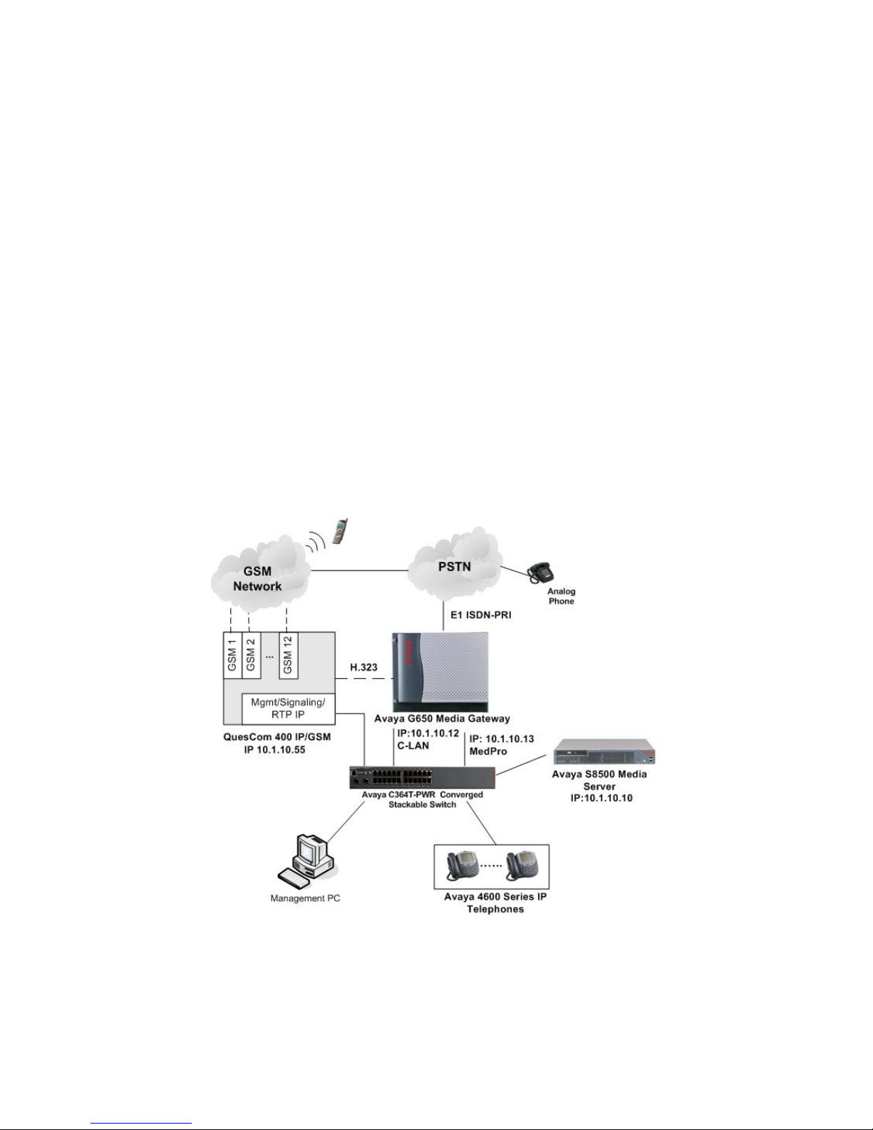
In Figure 1, Avaya Communication Manager runs on the Avaya S8500 Media Server. The
solution described herein is also extensible to other Avaya Media Servers and Media Gateways.
The Avaya G650 Media Gateway is connected to the PSTN via an E1 ISDN-PRI line and to the
QuesCom 400 IP/GSM via an H.323 IP trunk. The QuesCom in turn connects to the GSM
network via Subscriber Identity Module (SIM) cards that reside on GSM boards inserted in the
QuesCom 400 IP/GSM.
Figure 1: Avaya Communication Manager with QuesCom IP/GSM 400
HJP; Reviewed:
SPOC 9/14/2006
Solution & Interoperability Test Lab Application Notes
©2006 Avaya Inc. All Rights Reserved.
2 of 27
QuescomACM_H323
Page 3
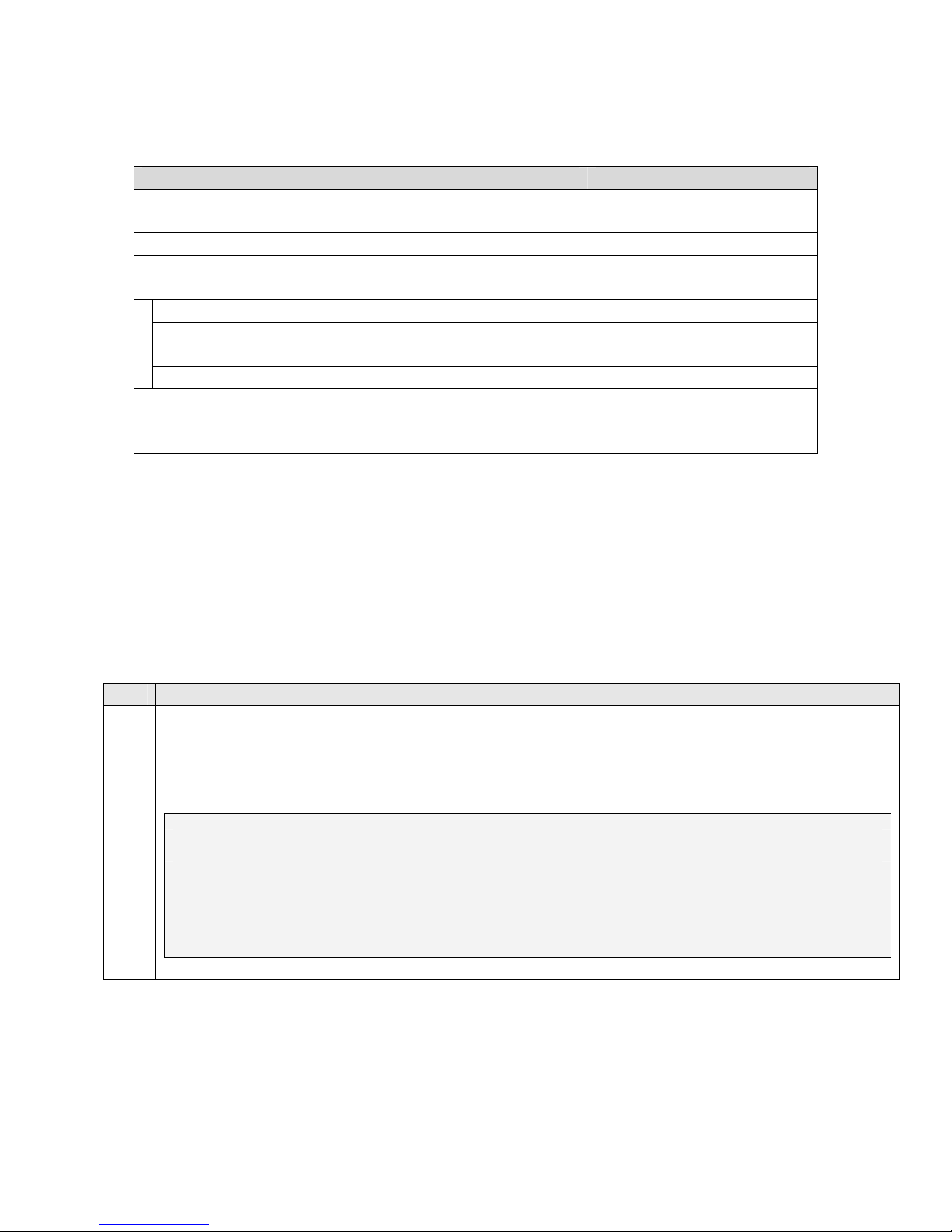
2. Equipment and Software Validated
Equipment Software
Avaya S8500 Media Server – Avaya Communication
3.1.2 (03.1-01.0.632.1)
Manager
Avaya C364T-PWR Converged Stackable Switch 4.3.12
Avaya 4620SW IP Telephones 2.2.3
Avaya G650 Media Gateway -
TN2312BP IP Server Interface 30
TN799DP C-LAN Interface 17
TN2302AP IP Media Processor 110
TN464CP DS1 Interface 18
QuesCom 400 IP/GSM
Additional patch needed during compliance testing
IAD04.20 B029 P006
ProxyH323.dll version
4.20.017
3. Configure Avaya Communication Manager
Initial configuration of Avaya Communication Manager is beyond the scope of these Application
Notes. See Section 9 for Avaya documentation references. This section illustrates the
configuration of the H.323 trunk groups and signalling groups, dial plan, ARS analysis, and route
patterns used in the compliance-tested configuration. The steps are performed from the System
Access Terminal (SAT) interface.
3.1. Avaya Communication System parameters Special Applications
Step Description
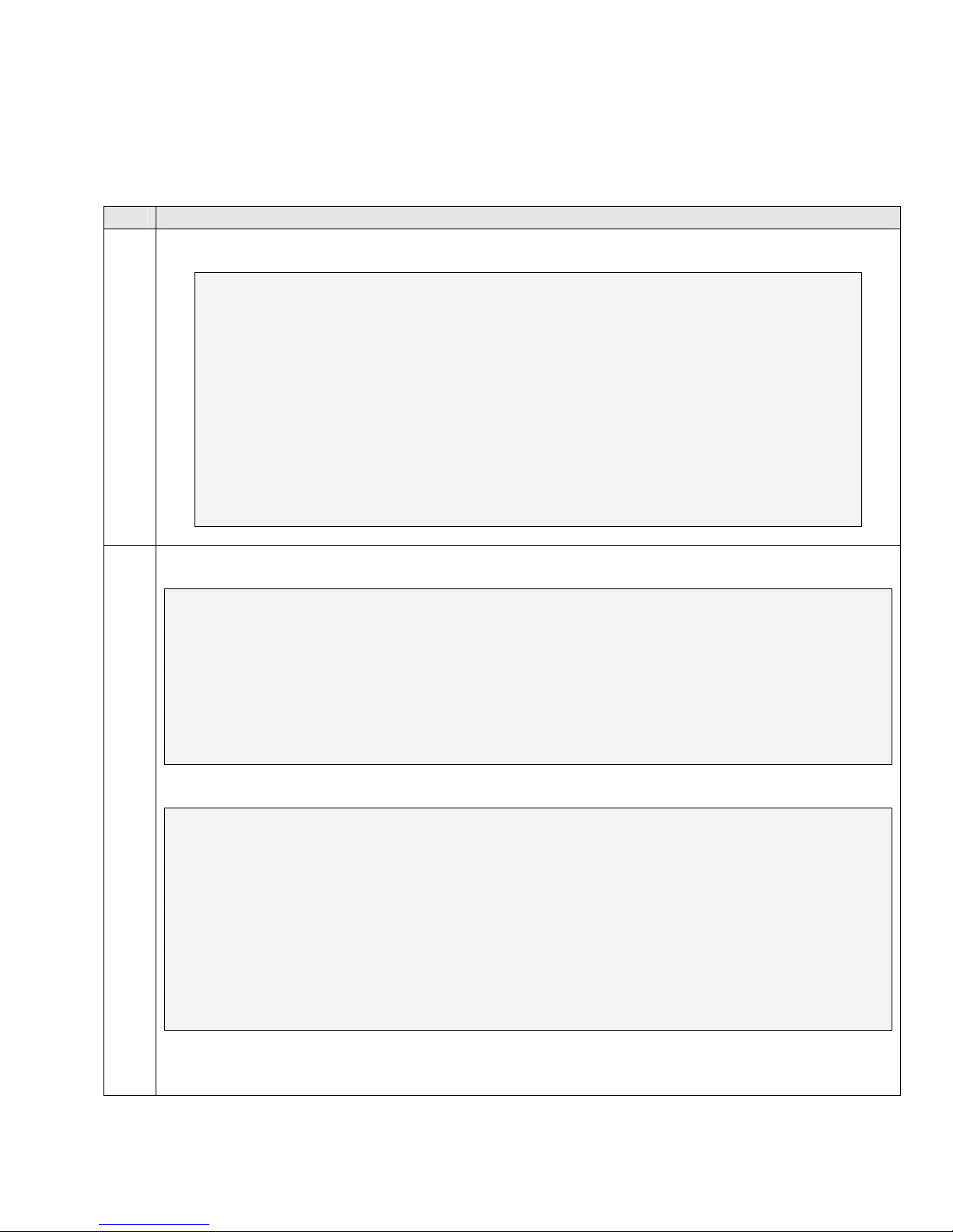
Display the system-parameters special-applications command and ensure that (SA8507) -
1.
H245 Support With Other Vendors? is set to “y”. If not, contact your Avaya authorized sales
representative to enable this feature. Note: This feature only needs to be enabled if FastStart is
enabled on the QuesCom 400 IP/GSM.
display system-parameters special-applications Page 4 of 6
SPECIAL APPLICATIONS
(SA8481) - Replace Calling Party Number with ASAI ANI? n
(SA8500) - Expanded UUI Display Information? n
(SA8506) - Altura Interoperability (FIPN)? n
(SA8507) - H245 Support With Other Vendors? y
(SA8508) - Multiple Emergency Access Codes? n
(SA8510) - NTT Mapping of ISDN Called-Party Subaddress IE? n
HJP; Reviewed:
SPOC 9/14/2006
Solution & Interoperability Test Lab Application Notes
©2006 Avaya Inc. All Rights Reserved.
3 of 27
QuescomACM_H323
Page 4
3.2. PSTN E1 ISDN-PRI
This section displays the PSTN E1 ISDN-PRI configuration on Avaya Communication Manager
in the sample configuration of Figure 1. See Section 9 for Avaya documentation references.
Step Description
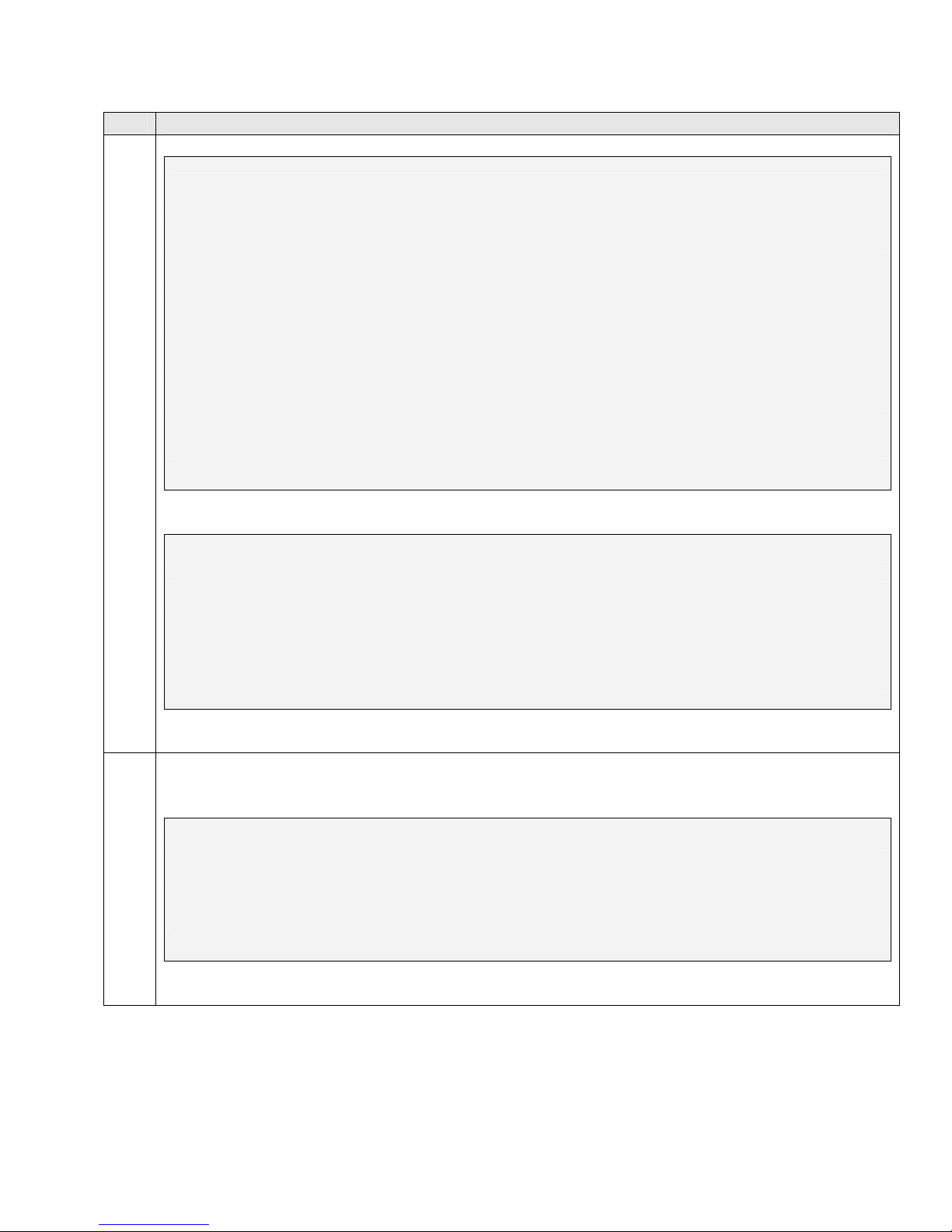
Enter the display ds1 <board location> to display the PSTN DS1 Circuit Pack configuration.
1.
display ds1 01A12
DS1 CIRCUIT PACK
Location: 01A12 Name: PRI to BT
Bit Rate: 2.048 Line Coding: hdb3
Signaling Mode: isdn-pri
Connect: network
TN-C7 Long Timers? n Country Protocol: etsi
Interworking Message: PROGress Protocol Version: b
Interface Companding: alaw CRC? y
Idle Code: 01010100
DCP/Analog Bearer Capability: 3.1kHz
T303 Timer(sec): 4
Slip Detection? n Near-end CSU Type: other
Enter the display trunk-group <number> to display the PSTN trunk-group configuration.
2.
display trunk-group 19 Page 1 of 22
TRUNK GROUP
Group Number: 19 Group Type: isdn CDR Reports: y
Group Name: PRI to BT COR: 1 TN: 1 TAC: 719
Direction: two-way Outgoing Display? n Carrier Medium: PRI/BRI
Dial Access? y Busy Threshold: 255 Night Service:
Queue Length: 0
Service Type: public-ntwrk Auth Code? n TestCall ITC: rest
Far End Test Line No:
TestCall BCC: 4
display trunk-group 19 Page 2 of 22
Group Type: isdn
TRUNK PARAMETERS
Codeset to Send Display: 6 Codeset to Send National IEs: 6
Max Message Size to Send: 260 Charge Advice: none
Supplementary Service Protocol: a Digit Handling (in/out): enbloc/overlap
Trunk Hunt: cyclical QSIG Value-Added? n
Digital Loss Group: 13
Incoming Calling Number - Delete: Insert: Format:
Bit Rate: 1200 Synchronization: async Duplex: full
Disconnect Supervision - In? y Out? n
Answer Supervision Timeout: 0
HJP; Reviewed:
SPOC 9/14/2006
Solution & Interoperability Test Lab Application Notes
©2006 Avaya Inc. All Rights Reserved.
4 of 27
QuescomACM_H323
Page 5
Step Description
display trunk-group 19 Page 3 of 22
TRUNK FEATURES
ACA Assignment? n Measured: both Wideband Support? n
Maintenance Tests? y
Data Restriction? n NCA-TSC Trunk Member:
Send Name: n Send Calling Number: y
Used for DCS? n Send EMU Visitor CPN? n
Suppress # Outpulsing? y Format: public
Outgoing Channel ID Encoding: preferred UUI IE Treatment: shared
Maximum Size of UUI IE Contents: 128
Replace Restricted Numbers? n
Replace Unavailable Numbers? n
Send Connected Number: y
Hold/Unhold Notifications? y
Send UUI IE? y Modify Tandem Calling Number? n
Send UCID? n BSR Reply-best DISC Cause Value: 31
Send Codeset 6/7 LAI IE? y Ds1 Echo Cancellation? n
Apply Local Ringback? n US NI Delayed Calling Name Update? n
Network (Japan) Needs Connect Before Disconnect? n
display trunk-group 19 Page 6 of 22
TRUNK GROUP
Administered Members (min/max): 1/5
GROUP MEMBER ASSIGNMENTS Total Administered Members: 5
Port Code Sfx Name Night Sig Grp
1: 01A1201 TN2464 C 19
2: 01A1202 TN2464 C 19
3: 01A1203 TN2464 C 19
4: 01A1204 TN2464 C 19
5: 01A1205 TN2464 C 19
Enter the display signaling-group <number> to display the PSTN signaling-group
3.
configuration.
display signaling-group 19 Page 1 of 5
SIGNALING GROUP
Group Number: 19 Group Type: isdn-pri
Associated Signaling? y Max number of NCA TSC: 5
Primary D-Channel: 01A1216 Max number of CA TSC: 5
Trunk Group for NCA TSC: 19
Trunk Group for Channel Selection: 19 X-Mobility/Wireless Type: NONE
Supplementary Service Protocol: a
HJP; Reviewed:
Solution & Interoperability Test Lab Application Notes
SPOC 9/14/2006
©2006 Avaya Inc. All Rights Reserved.
5 of 27
QuescomACM_H323
Page 6
3.3. H.323 Trunks and Signaling Groups
The steps in this section create an H.323 IP trunk group to the QuesCom 400 IP/GSM.
Step Description
Enter the change node-names ip command. Specify the node name and IP address for the
1.
QuesCom 400. Observe the node name of the C-LAN card shown in bold. These node names
will be used in the configuration of the H.323 signalling group in Step 4.
change node-names ip Page 1 of 1
IP NODE NAMES
Name IP Address Name IP Address
AEServer 10 .1 .10 .20 . . .
Abacus 10 .1 .10 .31 . . .
IPO412a_DC1 10 .1 .20 .10 . . .
Quescom 10 .1 .10 .55 . . .
S8300a_DC1 10 .1 .30 .10 . . .
S8500_Val1 10 .1 .10 .14 . . .
SEServer 10 .1 .10 .22 . . .
clan1a_DC1 10 .1 .10 .12 . . .
default 0 .0 .0 .0 . . .
medpro1a_DC1 10 .1 .10 .13 . . .
procr 10 .1 .10 .10 . . .
Enter the add trunk-group n command, where “n” is an available trunk group number. On
2.
Page 1 of the trunk-group form, configure the following:
• Group Type – set to “isdn”.
• Group Name – enter a meaningful name/description.
• TAC – enter a Trunk Access Code that is valid under the provisioned dial plan.
• Carrier Medium – set to “H.323”.
• Service Type – set to “tie”.
add trunk-group 27 Page 1 of 21
TRUNK GROUP
Group Number: 27 Group Type: isdn CDR Reports: y
Group Name: H.323 Quescom COR: 1 TN: 1 TAC: 727
Direction: two-way Outgoing Display? n Carrier Medium: H.323
Dial Access? y Busy Threshold: 255 Night Service:
Queue Length: 0
Service Type: tie Auth Code? n
Member Assignment Method: manual
HJP; Reviewed:
SPOC 9/14/2006
Solution & Interoperability Test Lab Application Notes
©2006 Avaya Inc. All Rights Reserved.
6 of 27
QuescomACM_H323
Page 7
Step Description
On the TRUNK FEATURES screen (Page 3 of the trunk-group form), set the Send Name, Send
3.
Calling Number and Send Connected Number to “y” and verify the Format is set to “public”
as shown below.
add trunk-group 27 Page 3 of 21
TRUNK FEATURES
ACA Assignment? n Measured: none
Internal Alert? n Maintenance Tests? y
Data Restriction? n NCA-TSC Trunk Member: 1
Send Name: y Send Calling Number: y
Used for DCS? n Send EMU Visitor CPN? n
Suppress # Outpulsing? n Format: public
UUI IE Treatment: service-provider
Replace Restricted Numbers? n
Replace Unavailable Numbers? n
Send Connected Number: y
Hold/Unhold Notifications? n
Enter the add signaling-group n command, where “n” is an unused signalling group number.
4.
On Page 1 of the form, configure the following:
• Group Type – set to “h.323”.
• Trunk Group for Channel Selection – enter the number of the trunk group configured
in Step 2.
• Near-end Node Name – enter the node name of a local C-LAN board from Step 1.
• Near-end Listen Port – specify the local listen port, typically 1720.
• Far-end Node Name – enter the node name of the QuesCom configured in Step 1.
• Far-end Listen Port – specify the listen port, typically 1720.
• Direct IP-IP Audio Connections – set to “n”.
add signaling-group 27 Page 1 of 5
SIGNALING GROUP
Group Number: 27 Group Type: h.323
Remote Office? n Max number of NCA TSC: 5
SBS? n Max number of CA TSC: 5
IP Video? n Trunk Group for NCA TSC: 27
Trunk Group for Channel Selection: 27
Supplementary Service Protocol: a
T303 Timer(sec): 10
Near-end Node Name: clan1a_DC1 Far-end Node Name: Quescom
Near-end Listen Port: 1720 Far-end Listen Port: 1720
Far-end Network Region: 1
LRQ Required? n Calls Share IP Signaling Connection? n
RRQ Required? n H245 Control Addr On FACility? n
Bypass If IP Threshold Exceeded? n
H.235 Annex H Required? n
DTMF over IP: out-of-band Direct IP-IP Audio Connections? n
IP Audio Hairpinning? n
Interworking Message: PROGress
HJP; Reviewed:
SPOC 9/14/2006
Solution & Interoperability Test Lab Application Notes
©2006 Avaya Inc. All Rights Reserved.
7 of 27
QuescomACM_H323
Page 8
Step Description
Enter the change trunk-group n command, where “n” is the trunk group number configured in
5.
Step 2. On Page 3 of the trunk-group form, configure the following:
• “IP” for Port. The number of ports configured should be coordinated with the number of
SIM cards available in the QuesCom 400 gateway.
• The number of the signaling group configured in Step 3 for Sig Grp.
change trunk-group 27 Page 5 of 21
TRUNK GROUP
Administered Members (min/max): 1/10
GROUP MEMBER ASSIGNMENTS Total Administered Members: 10
Port Name Night Sig Grp
1: IP 27
2: IP 27
3: IP 27
4: IP 27
5: IP 27
3.4. ARS Tables and Route Patterns
In the sample configuration described in these Application Notes, when placing outbound calls to
the public network, stations on Avaya Communication Manager must first dial the ARS Feature
Access Code (FAC) before dialing an external number. The single digit “9” was used as the
ARS FAC in the compliance-tested configuration (configuration step not shown).
Step Description
Enter the change ars analysis 0 command. Configure Dialed String entries according to
1.
customer requirements. In the example below, the entries match dialed numbers as follows:
• The “078” Dialed String matches 11-digit dialed numbers that begin with 078, and
routes calls to Route Pattern 78. For example, a dialed number of 07891 900 128 would
be matched by this entry.
change ars analysis 0 Page 1 of 2
ARS DIGIT ANALYSIS TABLE
Location: all Percent Full: 0
Dialed Total Route Call Node ANI
String Min Max Pattern Type Num Reqd
01 11 11 9 pubu n
078 11 11 78 pubu n
079 11 11 79 pubu n
123 3 3 9 pubu n
n
HJP; Reviewed:
SPOC 9/14/2006
Solution & Interoperability Test Lab Application Notes
©2006 Avaya Inc. All Rights Reserved.
8 of 27
QuescomACM_H323
Page 9

Step Description
Enter the change route-pattern n command, where “n” is the route pattern that processes dialed
2.
numbers configured in Step 1. Add two routing preference entries as follows:
1) First Routing Preference – H.323 IP trunk to QuesCom 400
• Grp No – enter the trunk group number routed to the QuesCom 400 gateway (see Section
3.3, Step 2)
• FRL - assign a Facility Restriction Level to this routing preference.
• LAR - set Look Ahead Routing to “next” to rehunt within the next routing preference if
calls are rejected. LAR allows Avaya Communication Manager to re-attempt the call on
another channel if the call is rejected with certain cause values.
2) Second Routing Preference – PSTN E1 ISDN-PRI
• Grp No – enter the trunk group that contains trunk members from the PSTN E1 ISDN-PRI
(see Section 3.2 Step 2).
• FRL - assign a Facility Restriction Level to this routing preference.
change route-pattern 78 Page 1 of 3
Pattern Number: 78 Pattern Name: Quescom H.323
SCCAN? n Secure SIP? n
Grp FRL NPA Pfx Hop Toll No. Inserted DCS/ IXC
No Mrk Lmt List Del Digits QSIG
Dgts Intw
1: 27 0 n user
2: 19 0 n user
3: n user
4: n user
5: n user
6: n user
BCC VALUE TSC CA-TSC ITC BCIE Service/Feature PARM No. Numbering LAR
0 1 2 3 4 W Request Dgts Format
Subaddress
1: y y y y y n n rest next
2: y y y y y n n rest none
3: y y y y y n n rest none
4: y y y y y n n rest none
5: y y y y y n n rest none
6: y y y y y n n rest none
HJP; Reviewed:
SPOC 9/14/2006
Solution & Interoperability Test Lab Application Notes
©2006 Avaya Inc. All Rights Reserved.
9 of 27
QuescomACM_H323
Page 10

3.5. Avaya Extension to Cellular(EC500) Configuration
Avaya Extension to Cellular allows a cell phone to be treated as if it were an extension defined in
Avaya Communication Manager. This is accomplished by mapping the user’s main office phone
to the cellular telephone number. All other types of calls, such as direct calls to and from the
published cell phone number, are unaffected by Extension to Cellular.
Step Description
Verify that the Avaya Communication Manager license has permissions for EC500 extensions.
1.
Enter the command display system-parameters customer-options. On the OPTIONAL
FEATURES screen, verify that the Maximum Off-PBX Telephones - EC500 is sufficient.
display system-parameters customer-options Page 1 of 11
OPTIONAL FEATURES
G3 Version: V13
Location: 2 RFA System ID (SID): 1
Platform: 12 RFA Module ID (MID): 1
USED
Platform Maximum Ports: 3200 259
Maximum Stations: 2400 209
Maximum XMOBILE Stations: 2400 0
Maximum Off-PBX Telephones - EC500: 2400 1
Maximum Off-PBX Telephones - OPS: 2400 32
Maximum Off-PBX Telephones - SCCAN: 2400 0
Enter the display system-parameters customer-options command. On the OPTIONAL
2.
FEATURES screen, ensure that Enhanced EC500? is set to “y” as shown below.
display system-parameters customer-options Page 4 of 11
OPTIONAL FEATURES
Emergency Access to Attendant? y IP Stations? y
Enable 'dadmin' Login? y Internet Protocol (IP) PNC? n
Enhanced Conferencing? y ISDN Feature Plus? n
Enhanced EC500? y ISDN Network Call Redirection? n
Enterprise Survivable Server? n ISDN-BRI Trunks? n
Enterprise Wide Licensing? n ISDN-PRI? y
ESS Administration? n Local Survivable Processor? n
Extended Cvg/Fwd Admin? y Malicious Call Trace? n
External Device Alarm Admin? n Media Encryption Over IP? n
Five Port Networks Max Per MCC? n Mode Code for Centralized Voice Mail? n
Flexible Billing? n
Forced Entry of Account Codes? n Multifrequency Signaling? y
Global Call Classification? y Multimedia Appl. Server Interface (MASI)? n
Hospitality (Basic)? y Multimedia Call Handling (Basic)? n
Hospitality (G3V3 Enhancements)? n Multimedia Call Handling (Enhanced)? n
IP Trunks? y
HJP; Reviewed:
SPOC 9/14/2006
Solution & Interoperability Test Lab Application Notes
©2006 Avaya Inc. All Rights Reserved.
10 of 27
QuescomACM_H323
Page 11

Step Description
Enter the change off-pbx-telephone configuration-set n, command, where “n” is an available
3.
configuration set number. Enter a descriptive name for the Configuration Set Description. The
rest of the parameters can be left with default values.
change off-pbx-telephone configuration-set 2 Page 1 of 1
CONFIGURATION SET: 2
Configuration Set Description: H323
Calling Number Style: network
CDR for Origination: phone-number
CDR for Calls to EC500 Destination? y
Fast Connect on Origination? n
Post Connect Dialing Options: dtmf
Cellular Voice Mail Detection: none
Barge-in Tone? n
Calling Number Verification? y
Identity When Bridging: principal
Enter the change off-pbx-telephone station-mapping n, command where “n” is the station that
4.
will be mapped to the cell phone. In the example below station “10000” is mapped to cell
number “07891900128”
• Station Extension – set to the office extension that will be mapped to the cell number.
• Application – enter “EC500”.
• Phone Number – enter the cell phone number.
• Trunk Selection – specify the outgoing trunk selection to “ars”.
• Configuration Set – enter the number of the configuration set configured in Step 3.
change off-pbx-telephone station-mapping 10000 Page 1 of 2
STATIONS WITH OFF-PBX TELEPHONE INTEGRATION
Station Application Dial Phone Number Trunk Configuration
Extension Prefix Selection Set
10000 EC500 - 07891900128 ars 2
-
-
Outside callers may use the QuesCom 400 to reach Avaya Communication Manager extensions
5.
by first calling a SIM card number on the QuesCom 400. The QuesCom 400 may be configured
to directly route incoming calls from the SIM card to a specific extension on Avaya
Communication Manager. If the extension is a Vector Directory Number (VDN), the vector
associated with the VDN may then prompt and collect digits from the caller. Alternatively, the
QuesCom 400 may be configured to prompt the caller to enter digits. The QuesCom 400 then
forwards the call to Avaya Communication Manager with the Called Party Number set to the
entered digits.
HJP; Reviewed:
SPOC 9/14/2006
Solution & Interoperability Test Lab Application Notes
©2006 Avaya Inc. All Rights Reserved.
11 of 27
QuescomACM_H323
Page 12

Step Description
Enter the change off-pbx-telephone feature-name-extensions and enter extensions to be
6.
associated with Avaya Communication Manager features. For example, Idle Appearance
Select can be used by an EC500 cell phone to make a call from an idle call appearance on the
mapped office extension.
change off-pbx-telephone feature-name-extensions Page 1 of 1
EXTENSIONS TO CALL WHICH ACTIVATE FEATURES BY NAME
Active Appearance Select: 10600 Idle Appearance Select: 10617
Automatic Call Back: 10601 Last Number Dialed: 10618
Automatic Call-Back Cancel: 10602 Malicious Call Trace:
Call Forward All: 10603 Malicious Call Trace Cancel:
Call Forward Busy/No Answer: 10604 Off-Pbx Call Enable: 10621
Call Forward Cancel: 10605 Off-Pbx Call Disable: 10622
Call Park: 10606 Priority Call: 10623
Call Park Answer Back: 10607 Send All Calls: 10624
Call Pick-Up: 10608 Send All Calls Cancel: 10625
Conference on Answer: 10609 Transfer On Hang-Up: 10626
Calling Number Block: 10610 Transfer to Voice Mail: 10627
Calling Number Unblock: 10611 Whisper Page Activation: 10628
Directed Call Pick-Up: 10612
Drop Last Added Party: 10613
Exclusion (Toggle On/Off): 10614
Extended Group Call Pickup:
Held Appearance Select: 10616
HJP; Reviewed:
SPOC 9/14/2006
Solution & Interoperability Test Lab Application Notes
©2006 Avaya Inc. All Rights Reserved.
12 of 27
QuescomACM_H323
Page 13

4. Configure the QuesCom 400 IP/GSM
This section describes the steps for configuring the QuesCom 400 gateway. The steps are
provided for illustration only; users should consult with Quescom for specific instructions.
4.1. QuesCom Server Configuration
Step Description
After the initial installation of the QuesCom server, telnet into the QuesCom server from the
1.
management PC shown in figure 1, using the default IP address “192.168.1.1.”. Log in using the
appropriate username and password.
C:\> telnet 192.168.1.1
login: administrator
Password: ********
Q400 IP/GSM Series, Serial# Q400-B4-00010381, Version IAD04.20B029P006
Security Patch SP001
Copyright (c) 1998-2005 QuesCom S.A.
At the prompt, type the following command gwconfig /setup.
X:\>gwconfig /setup
Application has been registered to the QCFGSvc
QCFGSvc Version 4.20.000.012
Copyright (c) 1998-2006 QuesCom S.A.
Enter “1” for English.
Enter the SmartIAD Administration language [1]:
1 English
2 French
3 German
> 1
GWconfig language: English
Enter a name for the QuesCom 400 gateway.
Setting up SmartIAD components...
Enter the SmartIAD network name [Q400]:Q400
SmartIAD Network Name: Q400
Enter IP address for the QuesCom gateway.
Enter the SmartIAD IP address [192.168.1.1]: 10.1.10.55
The SmartIAD IP address: 10.1.10.55
HJP; Reviewed:
SPOC 9/14/2006
Solution & Interoperability Test Lab Application Notes
©2006 Avaya Inc. All Rights Reserved.
13 of 27
QuescomACM_H323
Page 14

Step Description
Enter subnet mask or press enter to choose default.
Enter the SmartIAD subnet mask [255.255.255.0]:
The SmartIAD subnet mask: 255.255.255.0
Enter default Gateway IP address.
Enter the SmartIAD default Gateway [192.168.10.1]: 10.1.10.1
The SmartIAD default Gateway: 10.1.10.1
Enter “2” for United Kingdom
Enter the SmartIAD country code (ISDN, Tones, Numbering plan, Emails)
[1]:
1 France
2 United Kingdom
3 Germany
4 Other
> 2
ISDN Country: United Kingdom
IVR language country: ENG - English
Country Tones: United Kingdom
Country Numbering: United Kingdom
Network Operator: EuroISDN
Enter “0” for the server to operate in Stand-Alone mode.
Enter the 'Call Server' mode [0]:
0 Stand-Alone mode
1 Relay mode
> 0
Call Server mode: Stand-Alone
Enter Company Name. This can be any alphanumeric name.
Enter Company Name []: Avaya
Enter “0” to select the H.323 protocol.
Select the VoIP Protocol to use[0]:
0 H.323
1 SIP
> 0
VoIP Protocol: H.323
Enter “N” as the QuesCom 400 IP/GSM does not need to register to a GateKeeper in this
configuration.
Does the QuesCom IP/GSM need to register to a GateKeeper [Y/N]: N
HJP; Reviewed:
SPOC 9/14/2006
Solution & Interoperability Test Lab Application Notes
©2006 Avaya Inc. All Rights Reserved.
14 of 27
QuescomACM_H323
Page 15

Step Description
Enter the name for Avaya Communication Manager C-LAN board.
Enter the name of the H.323 Gateway: CM
H.323 Gateway name: CM
Enter the IP address for Avaya Communication Manager C-LAN board.
Enter the IP Address of the VoIP Gateway: 10.1.10.12
VoIP Gateway IP Address: 10.1.10.12
Follow the instruction and press any key to continue.
Selected parameters for Quick setup mode are:
SmartIAD Network Name: Q400
The SmartIAD IP address: 10.1.10.55
The SmartIAD subnet mask: 255.255.255.0
The SmartIAD default Gateway: 10.1.10.1
Press any key to continue..
Enter “1” to confirm the setup.
SmartIAD's serial number: Q400-B4-00010381
IVR language country: ENG - English
Email language country: ENG - English
Country Tones: United Kingdom
Country Numbering: United Kingdom
Call Server mode: Stand-Alone
Company Name: Avaya
VoIP Protocol: H.323
H.323 Gateway name = CM
H.323 Gateway IP Address = 10.1.10.12
Do you confirm this setup [1]:
0 No (to exit, and GWconfig /setup command can be re-entered)
1 Yes(to continue the setup and restart the QuesCom Q400)
> 1
Setup is confirmed.
Wait for 3 minutes for the QuesCom 400 gateway to reboot.
Setting up SmartIAD System Configuration...
Setting up Gateway Application...
Please wait...
Setting up Call Server Application...
Setting up QuesCom QGsm Application...
Setting up QuesCom Web Server Application...
Setting up QuesCom ODBC Socket Server Application...
Setting up QPortal Application...
Please wait...
Setting up NTPClient Application...
Setting up Pilot Application...
Setting up GeoPort Application...
Rebooting system...
SmartIAD, update process in progress... Warning: Do not restart the
Please, wait up to 3 minutes.
HJP; Reviewed:
SPOC 9/14/2006
Solution & Interoperability Test Lab Application Notes
©2006 Avaya Inc. All Rights Reserved.
15 of 27
QuescomACM_H323
Page 16

4.2. QuesCom Routing Configuration
Step Description
Open a web browser from the management PC and enter the following URL http://<QuesCom
1.
gateway IPaddress:8000>. For this configuration “
using the appropriate user name and password.
http://10.1.10.55:8000” was entered. Log in
On the left hand side of the screen under the QuesCom 400 menu. Click on Licenses and Profiles
2.
VoIP Profile. A default entry is created with Name “NO_RAS_H323” due to the initial
configuration in Section 4.1. Click on the pencil(edit) button next to the “NO_RAS_H323”
record.
HJP; Reviewed:
SPOC 9/14/2006
Solution & Interoperability Test Lab Application Notes
©2006 Avaya Inc. All Rights Reserved.
16 of 27
QuescomACM_H323
Page 17

Step Description
The following screen is presented for illustration. Default values may be retained on the VoIP
3.
Profile screen below.
On the left hand side of the screen under the QuesCom 400 menu, click on Objects Foreign
4.
Gatekeeper. An entry with the ID “CM” and the IP address of Avaya Communication Manager
C-LAN board is created due to the initial configuration in Section 4.1. Click on the pencil (edit)
button next to the “CM” record.
HJP; Reviewed:
SPOC 9/14/2006
Solution & Interoperability Test Lab Application Notes
©2006 Avaya Inc. All Rights Reserved.
17 of 27
QuescomACM_H323
Page 18

Step Description
Verify the VoIP Profile is set to “NO_RAS_H323”. No other changes need to be made to the
5.
default values on the Foreign Gatekeeper screen below.
Click on Services Service. Four entries are present by default. ID “3” is created by default and
6.
is routing for calls from Avaya Communication Manager to the QuesCom 400 gateway. ID “4” is
routing of outbound calls from the QuesCom 400 gateway to the GSM network. Click on the
pencil (edit) button next to ID “3” record.
HJP; Reviewed:
SPOC 9/14/2006
Solution & Interoperability Test Lab Application Notes
©2006 Avaya Inc. All Rights Reserved.
18 of 27
QuescomACM_H323
Page 19

Step Description
Verify the Call Type is set to “Foreign Gatekeeper”. No other changes need to be made to the
7.
default values for the record ID 3 on the Service screen below.
From the screen shown in Step 6, click the pencil (edit) button next to ID “4”. Verify the Call
8.
Type is set to “VoIP Outgoing”. No other changes need to be made to the default values for the
record ID 4 on the Service screen below.
HJP; Reviewed:
SPOC 9/14/2006
Solution & Interoperability Test Lab Application Notes
©2006 Avaya Inc. All Rights Reserved.
19 of 27
QuescomACM_H323
Page 20

Step Description
Routing of inbound calls to the QuesCom 400 gateway from the GSM network is created by
9.
clicking on the ADD RECORD button on the main Service screen shown in Step 6. On the
Service screen, configure the following as shown below.
• Origin Type – select radio button “Device”.
• Origin – select “Q400(SmartAD)”
• Called Prefix Number – enter “*”
• Call Type – select “GSM Incoming”
• Service type – select “VoIP”
• Destination Type – select radio button “Foreign GK”
• Device – select “CM”
The other parameters can be left with default values. Click on Save.
The inbound call route pattern added in Step 9 can be displayed on the main Service screen by
10.
clicking on Services Service.
HJP; Reviewed:
SPOC 9/14/2006
Solution & Interoperability Test Lab Application Notes
©2006 Avaya Inc. All Rights Reserved.
20 of 27
QuescomACM_H323
Page 21

Step Description
From the management PC shown in Figure 1, launch the QuesCom 400 QWA management
11.
console by clicking Start Programs QuesCom QuesCom Management Console. Right
click on Management Console and click New Call Server.
In the Connection dialog, configure the following, and click OK:
12.
• Hostname or IP address – enter the IP address of the QuesCom 400 gateway
• Host Alias – enter a descriptive name for the QuesCom 400 gateway
• User Name and Password
HJP; Reviewed:
SPOC 9/14/2006
Solution & Interoperability Test Lab Application Notes
©2006 Avaya Inc. All Rights Reserved.
21 of 27
QuescomACM_H323
Page 22

Step Description
Expand the Management Console tree by clicking on Q400(10.1.10.55) SmartIADs Q400
13.
GSM Device #0 Settings SubscriberNumber. In the Edit SubscriberNumber setting
dialog box, click on the Trunk 0 tab and enter the extension that incoming calls will be routed to in
the Value field. Replicate this field for all Trunk tabs 1 to 12 and click OK.
Right click on Q400 under SmartIADs and click on Save configuration, then right click back on
Q400 and click on Stop. Right click Q400 and click on Start and wait for the SIM cards to
register.
HJP; Reviewed:
SPOC 9/14/2006
Solution & Interoperability Test Lab Application Notes
©2006 Avaya Inc. All Rights Reserved.
22 of 27
QuescomACM_H323
Page 23

5. Interoperability Compliance Testing
The interoperability compliance testing focused on verifying the routing of inbound/outbound
calls to/from the QuesCom 400.
5.1. General Test Approach
The general approach was to place inbound and outbound calls through the QuesCom 400 and
verify successful call completion. The main objectives were to verify that:
• When internal extensions place outbound calls to GSM numbers, the calls are routed to
the QuesCom 400, and the QuesCom 400 decides on the least cost routing and routes the
call to the GSM network.
• When the landline is out of service, all outbound calls can successfully be routed via the
QuesCom 400 if need be.
• If the landline is operational, then Avaya Communication Manager will successfully reroute calls rejected by the QuesCom 400 to the landline. This can be configured to occur
for various reasons, such as no more free minutes left on the SIM cards.
• Inbound calls from the GSM network to the QuesCom 400 are successfully forwarded to
Avaya Communication Manager using both direct routing (mapping of a SIM card
phone number to an Avaya Communication Manager extension) and post-dialing (SIM
card answers an inbound call and upon a prompt, the external caller enters an Avaya
Communication Manager extension).
• Transfers and conferences between Avaya Communication Manager stations complete
properly on outbound and inbound calls routed through the QuesCom 400.
5.2. Test Results
The test objectives of Section 5.1 were verified. For serviceability testing, outbound and
inbound calls routed through the QuesCom 400 complete successfully after recovering from
failures such as Ethernet cable disconnects, and resets of Avaya Communication Manager and
the QuesCom 400.
The following are observations obtained from testing Avaya Extension to Cellular (EC500) with
QuesCom 400:
• Calls placed to EC500-enabled telephones on Avaya Communication Manager were
successfully extended to EC500-mapped external wireless telephones through the
QuesCom 400.
• EC500-mapped external wireless telephones successfully placed calls to Avaya
Communication Manager telephones through the QuesCom 400, and the displays of the
answering telephones showed the name and extensions of the corresponding EC500enabled telephones as the calling party.
• Avaya Extension to Cellular Feature Name Extensions were verified. For example,
EC500-mapped external wireless telephone callers successfully activated the Exclusion,
Idle Appearance Select, and Transfer on Hangup EC500 features through the QuesCom
400 by dialing the corresponding EC500 Feature Name Extensions.
HJP; Reviewed:
SPOC 9/14/2006
Solution & Interoperability Test Lab Application Notes
©2006 Avaya Inc. All Rights Reserved.
23 of 27
QuescomACM_H323
Page 24

6. Verification Steps
This section provides the tests that can be performed to verify proper configuration of Avaya
Communication Manager and QuesCom 400.
Step Description
1.
2.
From the SAT, enter the command status signaling-group s, where s is the number of a
signaling group configured in Section 3.3, and verify that the Group State is “in service”.
From the SAT, enter the command status trunk-group t, where t is the number of a trunk
group configured in Section 3.3, and verify that the Service States of all trunks are “inservice/idle” or “in-service/active”.
Expand the Management Console tree by clicking on Q400(10.1.10.55) SmartIADs Q400
GSM Device #0 Trunks/Channels Monitoring. Ensure the Trunks configured are the
colour green with IDLE.
HJP; Reviewed:
SPOC 9/14/2006
Solution & Interoperability Test Lab Application Notes
©2006 Avaya Inc. All Rights Reserved.
24 of 27
QuescomACM_H323
Page 25

Step Description
Expand the Management Console tree by clicking on Q400(10.1.10.55) SmartIADs Q400
3.
GSM Device #0 Networks Monitoring. Ensure the Signal(dBm) is above -90.
7. Support
Technical support from QuesCom can be requested in any of the following three ways.
- The corporate QuesCom Reporting Tool (QRT) account on the QuesCom web site at
http://support.quescom.com and follow instructions.
- The Support Line number. +33 820203846 (France) Voice Message is available during off
days and non-working time.
- Sending an email to
support@quescom.com
8. Conclusion
These Application Notes describe the configuration steps required for QuesCom IP/GSM 400 to
successfully interoperate with Avaya Communication Manager 3.1 using H.323 trunks. All
feature functionality, performance and serviceability test cases were completed successfully.
HJP; Reviewed:
SPOC 9/14/2006
Solution & Interoperability Test Lab Application Notes
©2006 Avaya Inc. All Rights Reserved.
25 of 27
QuescomACM_H323
Page 26

9. Additional References
This section references the Avaya and QuesCom IP/GSM 400 product documentation that are
relevant to these Application Notes.
The following Avaya Documents are available at
Administrator Guide for Avaya Communication Manager, Document ID 03-300509,
Issue 2, Feb 2006.
Administration for Network Connectivity for Avaya Communication Manager,
Document ID 555-233-504, Issue 11, Feb 2006.
The following documents can be obtained from QuesCom.
Getting Started with QuesCom 400 IP/GSM: GS-Q400IPGSM400-V01.pdf
QuesCom 400 IP/GSM Administrator Guide: AG-Q400IPGSM400-V01.pdf
How to configure an IP-GSM linked with an external H.323 gateway: Configuration of a
H323 IP-GSM.pdf
How to configure GSM Incoming calls to a remote Gatekeeper: Configuring GSM
incoming calls.pdf
http://support.avaya.com
HJP; Reviewed:
SPOC 9/14/2006
Solution & Interoperability Test Lab Application Notes
©2006 Avaya Inc. All Rights Reserved.
26 of 27
QuescomACM_H323
Page 27

©
2006 Avaya Inc. All Rights Reserved.
Avaya and the Avaya Logo are trademarks of Avaya Inc. All trademarks identified by ® and ™
are registered trademarks or trademarks, respectively, of Avaya Inc. All other trademarks are the
property of their respective owners. The information provided in these Application Notes is
subject to change without notice. The configurations, technical data, and recommendations
provided in these Application Notes are believed to be accurate and dependable, but are
presented without express or implied warranty. Users are responsible for their application of any
products specified in these Application Notes.
Please e-mail any questions or comments pertaining to these Application Notes along with the
full title name and filename, located in the lower right corner, directly to the Avaya
DeveloperConnection Program at devconnect@avaya.com.
HJP; Reviewed:
SPOC 9/14/2006
Solution & Interoperability Test Lab Application Notes
©2006 Avaya Inc. All Rights Reserved.
27 of 27
QuescomACM_H323
 Loading...