

Avaya Partner 18, Partner 18D, Partner 3910, Partner MLS 12, Partner 34D Programming And Use Manual
...Page 1

AT&T
PARTNER® Plus
Communications System
Release 3.1
Programming and Use
Page 2

Copyright © 1993 AT&T
All Rights Reserved
Printed in U.S.A.
AT&T 518-455-217
Issue 1
October 1993
Notice
Every effort was made to ensure that the information in this book was complete and accurate at the
time of printing. However, information is subject to change.
Federal Communications Commission (FCC) Interference Notice
This equipment has been tested and found to comply with the limits of a Class A digital device,
pursuant to Part 15 of FCC rules. For additional FCC information, see Appendix C of this book.
Canadian Emissions Requirements
This digital apparatus does not exceed the Class A limits for radio noise emissions from digital
apparatus set out in the Radio Interference Regulations of the Canadian Department of
Communications (DOC). For additional DOC information, see Appendix C of this book.
Le present appareil numerique n’emet pas de bruits radioelectriques depassant les limites
applicable aux appareils numeriques de la classe A prescrites dans le Reglement sur le brouillage
radioelectrique edicte par le ministere des Communications du Canada. Vous trouverez des
renseignements complémitaires à la annexe C de ce manuel.
Security
As a customer of new telecommunications equipment, you should be aware of the significant and
growing problem of theft of long distance services by third parties, known commonly as “toll fraud.”
It is particularly important that you understand and take appropriate steps to deal with this crime
because under applicable tariffs, you will be responsible for payment of associated toll charges.
AT&T cannot be responsible for such charges and will not make any allowance or give any credit
resulting from toll fraud.
Toll fraud can occur despite the preventive efforts of network providers and equipment
manufacturers. Toll fraud is a potential risk for every customer with telecommunications equipment
having one or more of the following features: (1) remote access, (2) automated attendant, (3) voice
mail, (4) remote administration and maintenance, and (5) call forwarding (remote). This is not a
product or design defect, but a risk associated with equipment having one or more of the features
described above. If your new telecommunications equipment possesses any of these features,
please consult the relevant portion of your documentation for further details and specific procedures
to reduce the risk of toll fraud or contact your AT&T dealer for further details.
Trademarks
Call Assistant, PARTNER MAIL, PARTNER MAIL VS, and PassageWay are trademarks of AT&T.
Magic on Hold, MERLIN, MLS-34D, MLS-18D, MLS-12D, MLS-12, MLS-6, PagePac, PARTNER, and
SYSTIMAX are registered trademarks of AT&T. Microsoft is a registered trademark and Windows is a
trademark of Microsoft Corporation.
Warranty
AT&T provides a limited warranty to this product. Refer to “AT&T Limited Warranty and Limitation of
Liability” in Appendix B of this book.
Ordering Information
The order number for this book is 518-455-217. To order additional books, call 1 800 432-6600 in the
continental U.S. and 1 800 255-1242 in Canada. For information about ordering other system
reference materials, replacement parts, accessories, and other compatible equipment, refer to
“Product Ordering Information” in Appendix B.
Support Telephone Number
In the continental U.S., AT&T provides a toll-free customer helpline 24 hours a day. Call the
AT&T Helpline at 1 800 628-2888 if you need assistance when programming or using your
system.
Outside the continental U.S., contact your local AT&T Authorized Dealer.
Page 3

Contents
About This Guide
v
1
Overview
1-i
■
■
■
■
Important Safety Instructions
1-ii
Features and Capabilities
1-1
System Components
1-2
Auxiliary Equipment
1-6
2
Programming
2-i
■
■
■
■
■
Overview
Hardware Considerations
Initial System Setup
Changing Settings After Installation
Changing Settings to Support PBX or
Centrex Services
System Programming Options
Using System Programming
Telephone Programming Options
Using Telephone Programming
2-1
2-2
2-3
2-5
■
■
■
■
2-6
2-7
2-12
2-15
2-17
3
Learning About Telephones
3-i
■
System Telephones
3-1
■
Standard Telephones
3-7
■
Combination Extensions
3-10
■ Using Telephones
3-11
i
Page 4

Contents
4
Using Auxiliary Equipment
4-i
■
■
■
■
■
■
■
■
■
Overview
Answering Machines
Call Reporting Devices (SMDR)
Credit Card Scanners
Fax Machines
Modems
Night Service with Auxiliary Equipment
PARTNER Attendant
Voice Messaging Systems
4-1
4-4
4-8
4-11
4-12
4-19
4-21
4-23
4-24
5
Feature Reference
5-i
6
Troubleshooting
■
When You Need Help
■
Power Failure Operation
■
Problems with System Phones
■
Problems with Standard Phones
■ Problems with Combination Extensions
■
Other Problems with Phones
■
Problems with Standard Devices
■
System Problems
6-i
6-1
6-1
6-2
6-4
6-6
6-7
6-10
6-10
A
Specifications
A-1
B
Maintenance, Repair, and
Ordering Information
B-1
ii
Page 5

Contents
C
FCC Information
C-1
D Speed Dial Form
D-1
GL
Glossary
GL-1
IN
Index
IN-1
Programming Quick References
Inside back cover
iii
Page 6

About This Guide
Purpose
This guide is intended for the system manager. It explains what the
PARTNER® Plus Communications System can do, provides instructions for
programming and using the system, and tells how to get the most out of its
many features and capabilities.
Terminology
Throughout this guide, the PARTNER Plus Communications System is referred to
simply as the system and AT&T telephones specifically designed to work with
the system are called system phones. You can also use industry-standard
telephones with the system, which are referred to as standard phones in this
guide. Finally, the PARTNER MAIL VS™ or PARTNER MAIL™ Voice Messaging
System, which you may have connected to the system, is referred to as the
voice messaging system.
How to Use This Guide
For information on the following topics, refer to the appropriate chapter:
■
■
■
Getting Acquainted. Chapter 1 provides an overview of system features
and hardware components.
Programming the System. You can change your system’s settings
easily to accommodate new or expanding needs. Chapter 2 provides
general programming information, while Chapter 5 provides detailed
instructions for programming specific system features.
Training Co-Workers. Chapter 3 explains how system and standard
phones work with the system. To help train co-workers on telephone
basics, you can share this information with them.
About This Guide
v
Page 7

■
■
■
Using Auxiliary Equipment. The system supports a wide variety of
auxiliary equipment, including fax machines, modems, voice messaging
systems, and call reporting devices. Chapter 4 provides advice on
setting up these devices to work effectively with the system.
Daily Operation. Depending on how your system is set up, you may
need to oversee some of the system’s daily operations. For example, you
may need to turn on Night Service at the end of each day before leaving
the office. Reference information on all features, including descriptions
and instructions for using each feature, is provided in Chapter 5.
Solving Problems. Chapter 6 provides information on solving problems
if your system or telephones malfunction.
Once you are experienced with the system, use the Table of Contents or Index
to locate the information you need.
Throughout this guide, feature names are printed in bold so you can easily look
up the name in Chapter 5, “Feature Reference,” for additional information on the
feature. For example, if you see a reference to System Date (#101), you can
look it up in Chapter 5 for details.
Product Safety Statements
Product safety statements are identified in this guide by a
CAUTION:
Indicates the presence of a hazard that will or can cause minor personal
injury or property damage if the hazard is not avoided.
WARNING:
Indicates the presence of a hazard that can cause severe or fatal
personal injury if the hazard is not avoided.
How to Comment on This Guide
A feedback form is located at the end of this guide, after the appendixes. If the
form is missing, send your comments and recommendations for changes to
Documentation Manager, AT&T, 200 Laurel Avenue (Room 4E-409),
Middletown, NJ 07748 (FAX 908 957-4009).
vi
About This Guide
Page 8

Overview
1
Contents
Important Safety Instructions
Features and Capabilities
System Components
■
Control Unit
System Modules
System Capacity
■
Telephones
System Telephones
Intercom Autodialers
Standard Telephones
Auxiliary Equipment
■
Requirements
■
Connecting Standard Devices
ii
1-1
1-2
1-2
1-4
1-4
1-5
1-5
1-5
1-6
1-6
1-7
1-7
1-i
Page 9

Important Safety Instructions
WARNING:
The following list provides basic safety precautions that should always
be followed when using your telephone equipment:
1.
2.
3.
4.
5.
6.
7.
8.
9.
Read and understand all instructions.
Follow all warnings and instructions marked on the product.
Unplug all telephone connections before cleaning. DO NOT use liquid
cleaners or aerosol cleaners. Use a damp cloth for cleaning.
This product should be serviced by (or taken to) a qualified repair
center when service or repair work is required.
DO NOT use this product near water, for example, in a wet basement
location
DO NOT place this product on an unstable cart, stand, or table.
Never push objects of any kind into slots or openings as they may
touch dangerous voltage points or short out parts that could result in
a risk of fire or electric shock. Never spill liquid of any kind on the
product.
Avoid using this telephone during an electrical storm. There may be a
remote risk of electric shock from lightning.
DO NOT use the telephone to report a gas leak in the vicinity of the
leak.
10. The product is provided with a three-wire grounding type plug. This
is a safety feature. DO NOT defeat the safety purpose of the
grounding type plug. DO NOT staple or otherwise attach the AC
power supply cord to building surfaces.
CAUTION:
DO NOT block or cover the ventilation slots and openings. They prevent
the product from overheating. DO NOT place the product in a separate
enclosure unless proper ventilation is provided.
SAVE THESE INSTRUCTIONS
1-ii
Page 10

Overview
1
Features and Capabilities
The following list provides an overview of the system’s features:
■
■
■
■
■
■
■
■
■
Full line of system phones, providing access to multiple lines from a
single phone at each extension.
Programmable buttons on system phones, providing one-touch access to
system features simply by pressing the button.
Intuitive operation of basic call handling capabilities including transfer,
conference, and hold.
Intercom (inside) calling to other system extensions using an Intercom
button and the two-digit number assigned to the extension. Users can
either ring or voice signal an idle system phone, or use Voice Interrupt On
Busy to signal another user who is active on a call.
Grouping of extensions for flexibility in directing and answering calls.
Integrated voice messaging support with the PARTNER MAIL VS system
or PARTNER MAIL system, so callers can reach a desired extension or
group without operator assistance and leave messages at unanswered or
busy extensions.
Power failure operation with standard phones, allowing you to make and
receive calls during a power failure while retaining programmed
equipment settings for up to four days. (An optional Uninterruptible
Power Supply, or UPS, is also available to allow full equipment operation
during a power failure.)
Centrex or PBX operation support—including one-touch dialing of feature
access codes on system phones.
Flexible dialing restrictions and permissions so you can control telephone
activity and phone bills.
Overview
1-1
Page 11

■
■
■
■
■
■
Special hospitality features that let Bed and Breakfast proprietors, for
example, regulate phone use in guest rooms and schedule wake up calls
for guests.
Easy-to-use programming procedures, making it simple for you to
manage your system and telephones. System display phones provide
feedback during programming.
Two system programming extensions, allowing you to program the
system from one extension without interrupting call activity at the other
programming extension—usually the receptionist’s extension.
Modular connections to the control unit, making it easy to reconfigure
your system or to add lines and/or extensions as your business grows.
Direct connections for industry-standard devices—including most
standard phones, fax machines, answering machines, modems, and
credit card scanners.
Optional equipment support, including doorphones, loudspeaker paging
systems, music on hold*, call reporting (often referred to as Station
Message Detail Recording or SMDR) devices, PARTNER Attendant, and
extra alerts.
System Components
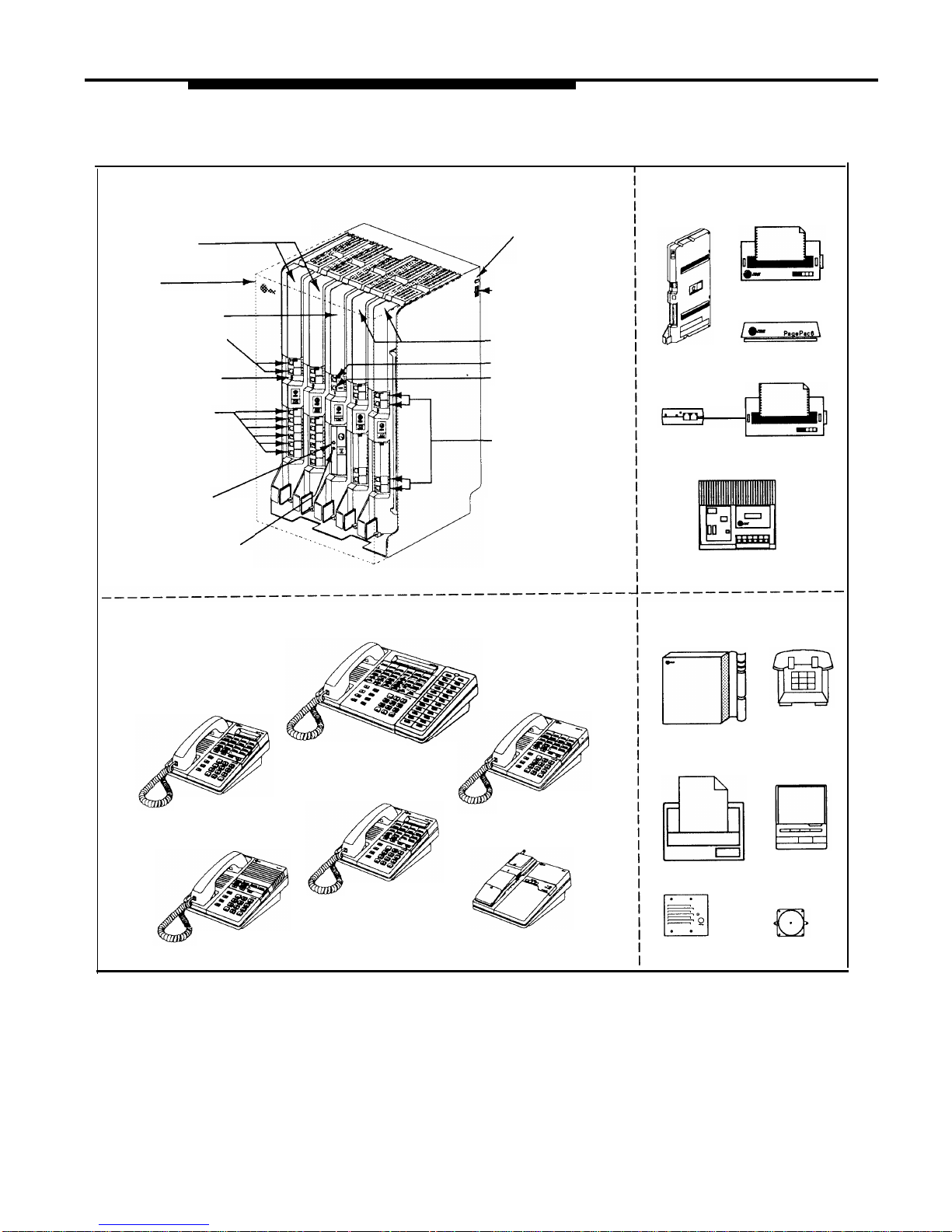
Modular hardware design makes the system easy to install and expand. Figure
1-1 shows an example of system components.
Control Unit
The control unit is the heart of the system; it includes a backplane and a cover,
and it houses the system modules. All system modules slide into the
backplane, which channels power to the system. The cover slides onto the front
of the backplane after all the system modules have been installed.
WARNING:
There are no customer-serviceable components inside the system
modules or backplane. There are hazardous voltages within that can
cause severe or fatal personal injury. DO NOT OPEN THE MODULES.
*
If you use music-on-hold to broadcast certain copyrighted music or material, including songs or other
material from radio broadcasts, you may be required to obtain the permission of the copyright owner. One
way to obtain permission is to contact ASCAP, BMI, and/or similar performing rights organizations, to obtain
a license. Or, you can purchase a Magic on Hold® system from AT&T, which does not require you to obtain
such a license. AT&T disclaims any liability arising out of the failure to obtain such a license, if required.
1-2
Overview
Page 12
CONTROL UNIT
Optional/Devices
(for the control unit)
Main
Circuit Breaker
206 Modules
Cover
Power Cord
Receptacle
Processor Module
Outside Line Jacks
400 Modules
PAGE Jack
SMDR Jack
Power Indicators
Voice Messaging
System
(LEDs)
Extension Jacks
(206 modules only)
Outside
Line Jacks
AT&T Call Accounting
Terminal (Basic or Plus)
MUSIC ON HOLD
Volume Adjustment Screw
MUSIC ON HOLD Jack
AT&T Serial
Printer
PARTNER
AT&T Paging
MAIL VS
System
(for RCA phono plug)
AT&T Magic on Hold® deck
SYSTEM PHONES
MLS-34D® Phone
(with optional MLS-CA24
Intercom Autodialer)
MLS-12® Phone
MLS-18D® Phone
MLS-12D® Phone
Optional Devices
(for extension jacks)
PARTNER MAIL
Voice Messaging
System
Fax Machine
Standard
Touch-Tone
Phone
Answering
Machine
Alert
MLS-6® Phone
MLC-6 Phone
Doorphone
Figure 1-1.
Sample System Components
Overview
1-3
Page 13

System Modules
The following system modules can be installed in your system:
■
■
■
Processor Module provides the software intelligence that controls the
system’s features. It has jacks for a music-on-hold audio source, a
loudspeaker paging system, and a call reporting (SMDR) device, such as
a printer.
206E Module has jacks to connect a maximum of two outside telephone
lines and six extensions to the system. You can connect telephones and
other telecommunications devices (such as fax machines and modems)
to the extension jacks (either directly or through your building’s modular
wall jacks). Each 206E module has a green power indicator that shows it
is receiving power. The system requires at least one 206E module.
400E Module is similar to the 206E module, but without extension jacks.
It has four outside line jacks. This module is an inexpensive way to add
lines when you do not need more extensions.
If you are upgrading from a PARTNER system or a previous release of a
PARTNER Plus system, you can still use its 200 modules, each providing two
line jacks.
If you want message waiting capability on standard phones that are equipped
with message waiting lights, you must connect those phones to extension jacks
on Release 3.1 (R3.1) 206 modules. Additionally, you need an R3.1 processor
module.
Hereafter, references to 206 modules include 206E and all 206 modules used
with previous releases of the product. Similarly, references to 400 modules
include 400E and all 400 modules used with previous releases of the product.
System Capacity
The combination of 206 and 400 modules installed determines the number of
available lines and extensions. The system allows up to 12 lines and up to 24
extensions; however, these maximums cannot be achieved simultaneously:
■ For maximum line capacity (12 lines), install two 206 modules and two
400 modules. This arrangement allows up to 12 extensions.
■
For maximum extension capacity (24 extensions), install four 206
modules. This arrangement allows up to 8 lines.
1-4
Overview
Page 14

Telephones
System Telephones
This guide refers to AT&T telephones specifically designed to work with the
system as system phones. These include the MLS-34D, MLS-18D, MLS-12D,
MLS-12, MLS-6, and MLC-6 telephones.
System phones have several buttons in common: volume control buttons, and
the
Feature
,
Conf
,
Transfer
,
and
Hold
buttons. In addition, each phone has
programmable buttons that can be used for outside lines, extension numbers,
outside phone numbers, or system features. Outside lines, as well as some
system features, require buttons with status lights. Programmable buttons
without lines assigned to them can be programmed with numbers or features, so
you can use the feature or dial the number with one touch. The number in each
model name indicates the number of programmable buttons with status lights
plus two
Intercom
buttons.
If the system phone has a display, indicated by a “D” in the model name, users
receive messages and prompts when making calls and programming. (More
information about the display is provided in Chapter 5.) A system display phone
is required for system programming. It must be as large as the largest phone in
the system, because an MLS-12D or MLS-18D cannot program an MLS-34D.
Similarly, an MLS-12D cannot program an MLS-18D.
Table 1-1 summarizes system phone features.
Table 1-1. System Phones
MLS-34D MLS-18D
MLS-12D MLS-12
MLS-6
MLC-6
Total Number of
32
16
16
16
4 4
Programmable Buttons
Line Capacity (Number of
Programmable Buttons with
12*
12*
10
10
4
4
Status Lights)
Intercom Buttons
2
2
2
2 2 2
Display
✔
✔
✔
—
—
—
Speaker
✔ ✔
✔
✔ ✔
—
Microphone
✔ ✔
✔ ✔
—
—
Intercom Autodialers
The system phones at extensions 10 and 11 each support one MLS-CA24
Call Assistant™ Intercom Autodialer, which provides Auto Dial buttons for all of
the extensions in your system (up to 24). The Auto Dial buttons allow users to
dial and transfer calls to system extensions with one touch. The status lights for
the buttons also indicate calling activity at each extension. For more
information, see “Auto Dialing” in Chapter 5.
*
The MLS-34D has 32 programmable buttons with status lights and the MLS-18D has 16 programmable
buttons with status lights. Since the system supports a maximum of 12 lines, you can use up to 12 buttons
on these phones for outside lines.
Overview
1-5
Page 15

Standard Telephones
You can also use industry-standard single-line rotary or touch-tone telephones,
including feature phones with built-in feature buttons and lights, with the system.
This guide refers to such telephones as standard phones. AT&T-certified
standard phones, such as the 8110 Analog Telephone, are recommended.
The following standard phones with message waiting lights are compatible with
the system:
■
■
Single-Line Telephone with Message Waiting Light and Recall Button
(2500 YMGK)
7102 Plus Analog Voice Terminal
Check with your local AT&T Authorized Dealer to find out if other standard
phones with message waiting lights will work.
NOTE:
For message waiting capability, you must connect standard phones with
message waiting lights to Release 3.1 (R3.1) 206 modules, and equip the
system with an R3.1 processor module. This message waiting capability does
not apply to standard phones with neon-type message waiting lights.
Auxiliary Equipment
You can connect many types of telecommunications devices to your system
without expensive adapters or additional phone lines. Many industry-standard,
single-line devices will work with the system regardless of the manufacturer:
■
■
■
■
■
Touch-tone, rotary, and cordless telephones (such as those you might
have in your home)
Fax machines
Answering machines
Modems
Credit card scanners
There are several other devices that may be compatible with the system. For
more information, refer to the list in Chapter 4 or contact your local AT&T
Authorized Dealer. Also, see Chapter 4 for advice on setting up auxiliary
equipment to work effectively with the system.
1-6
Overview
Page 16

Requirements
An industry-standard device must meet the following conditions:
It must be non-proprietary. That is, it cannot be made specifically for use
on a particular telephone system. (For example, you cannot connect an
AT&T MERLIN® phone because it is specifically designed for use on a
MERLIN system.)
Its Ringer Equivalence Number (REN*) cannot be greater than 2.0. (The
REN is shown on a label on the device, usually on the bottom.)
■
■
■
You can connect a standard two-line device to the system, but for best
results it should be installed and used as if it were a single-line device.
Connecting Standard Devices
You can connect a standard device so that it is on an extension by itself, or so
that it shares an extension with another piece of equipment (either another
standard device or a system phone) as long as the REN of the two devices
together does not exceed 2.0. (System phones have 0.0 REN.) For example,
you can connect a standard phone and an answering machine to the same
extension. An extension with two devices connected to it is called a
combination extension. You cannot connect two system phones on one
extension. The PARTNER Plus Communications System Installation guide
provides installation instructions.
*
REN is a measure of the power it takes to ring a phone. The typical home phone line handles 4.0–5.0 RENs;
each extension jack in your system handles up to 2.0 RENs.
Overview 1-7
Page 17

Programming
2
Contents
Overview
Hardware Considerations
Initial System Setup
■ Setting the System Clock
■ Assigning Lines
■
Customizing Extensions
■
Copy Settings
Changing Settings after Installation
■ Changing the System Clock
■ Adding New Lines
■
Adding New Extensions
■
Swapping Extensions
Changing Settings to Support PBX or
Centrex Services
■
Recall Setting
■
Dialing Restrictions
■ Speed Dial and Auto Dial Numbers
System Programming Options
■ Speed Dialing
■
Dialing Restrictions and Permissions
Restricting Access to Outside Lines
Controlling Calls on Outside Lines
Overriding Dialing Restrictions
Summary
■
Setting Up Groups of Extensions
■ Setting Up Auxiliary Equipment
■
Hospitality Features
2-1
2-2
2-3
2-3
2-3
2-4
2-4
2-5
2-5
2-5
2-5
2-5
2-6
2-6
2-6
2-6
2-7
2-7
2-7
2-7
2-8
2-8
2-9
2-10
2-10
2-11
2-i
Page 18

Contents
Using System Programming
■
The Programming Overlays
■
Programming Mode
■ Changing Programming Type
Telephone Programming Options
■
Automatic Line Selection
■ Extension Name on Display
■
Line Ringing
■
Personal Speed Dialing
■
Programming Telephone Buttons
■ Programming a Receptionist’s Extension
Call Handling Options
Button Programming
Using Telephone Programming
■
Telephone Models
■ Using Centralized Telephone Programming
■ Changing Programming Type
■ Using Extension Programming
2-ii
2-12
2-12
2-14
2-14
2-15
2-15
2-15
2-15
2-15
2-15
2-16
2-16
2-16
2-17
2-17
2-17
2-20
2-20
Page 19

Programming
2
Overview
After the system hardware is installed, you can customize the system and
individual telephones. This chapter explains how to use programming to
accomplish that.
There are two types of programming:
■
System Programming allows you to customize the system to meet the
needs of your business. When the system is first installed, it uses factory
settings that reflect the most commonly used options. You can change
system settings as needed.
You can perform System Programming from either extension 10 or 11.
Because an extension cannot be in programming mode and handle
calls at the same time, consider using extension 11 for programming.
Doing so gives you the ability to program without disrupting call
handling by the receptionist at extension 10.
■ Telephone Programming allows telephones to be customized to meet
individual users’ needs. Individual telephones can be programmed either
from extension 10 or 11 (called Centralized Telephone Programming), or
from a user’s extension using a system phone (called Extension
Programming).
A system display phone is required for System and Centralized Telephone
Programming. Make sure that the programming phone is as large as the largest
phone in the system, because an MLS-12D or MLS-18D cannot program an
MLS-34D. Similarly, an MLS-12D cannot program an MLS-18D.
This chapter provides general information on programming procedures. When a
specific feature name is referenced, it is printed in bold type. For detailed
descriptions and step-by-step instructions, refer to that name in Chapter 5.
(Brief summaries of all programming procedures are at the end of this book.)
Programming
2-1
Page 20
Hardware Considerations
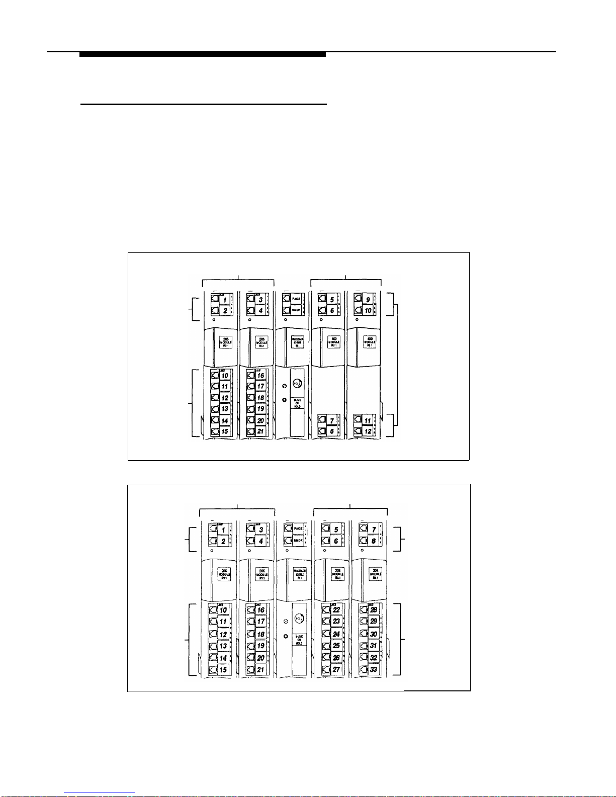
Programming procedures use line and extension numbers. The line number
represents the line jack on a 206 or 400 module to which the outside line is
connected. Similarly, the extension number represents the extension jack on a
206 module to which the system phone or standard device is connected.
For each 206 module, the system assigns two lines and six extensions; for each
400 module, the system assigns four lines. The system numbers lines and
extensions consecutively. Figure 2-1 shows the numbering scheme for a
system with maximum lines. Figure 2-2 shows the numbering scheme for a
system with maximum extensions. However, your system can have any number
of lines and extensions up to the maximum.
206 Modules
400 Modules
Line Jacks
Extension
Jacks
Line Jacks
Line Jacks
Figure 2-1.
Maximum Lines
206 Modules 206 Modules
Line Jacks
Line Jacks
Extension
Jacks
Extension
Jacks
Figure 2-2. Maximum Extensions
2-2
Programming
Page 21

Initial System Setup
After the control unit is installed, you set up the system using a combination of
system and telephone programming procedures. In this guide, System
Programming procedures are identified by a code (# and three digits);
Telephone Programming procedures are identified by the feature name only.
Use the System Planner as a guide when programming. The following sections
provide an overview of the procedures you use for initial system setup. See
Chapter 5 for more information on specific procedures. Other programming
procedures are optional, but strongly recommended to make the most of your
investment. (See “System Programming Options” and “Telephone Programming
Options” later in this chapter for details.)
Setting the System Clock
After supplying power to the control unit, use the following procedures:
■
System Date (#101) to set the month and day.
■
System Day (#102) to set the day of the week.
■
System Time (#103)
to set the hour and minutes.
Assigning Lines
For initial setup only, use Number of Lines (#104) to specify the number of lines
that will be assigned to all system extensions. Then use the following
procedures as needed:
■
■
■
■
■
Dial Mode (#201) to identify any rotary lines (the default for all lines is
“touch-tone”).
Line Assignment (#301) to assign lines to specific extensions (if the line
was not assigned using the Number of Lines procedure), to remove lines
from some extensions, or to change the button used to pick up a line at a
specific extension.
Line Access Restriction (#302) to limit an extension’s access to a
specific line.
Line Ringing (Centralized Telephone Programming) to specify when a
line will start ringing at each extension that has the line. For additional
information on line ringing options, see “Programming a Receptionist’s
Extension” later in this chapter.
Automatic Line Selection (Centralized Telephone Programming) to
specify the order in which the system tries to select an available line
(intercom or outside), when a user at the extension lifts the handset or
presses
Spkr to make a call without first selecting a specific line button.
For extensions with standard phones, set Automatic Line Selection
to intercom first. This enables standard phones to access equipment
features, including intercom calling. When users lift the handsets on
standard phones, they hear intercom dial tone. To access an outside
line, they must dial 9.
Programming
2-3
Page 22

Customizing Extensions
In addition to line assignments, the following procedures can be used to
customize an extension:
■
■
■
■
■
■
■
■
Display Language (#303) to specify the language (English, French, or
Spanish) for messages that appear on a system display phone.
Automatic Extension Privacy (#304) to prevent other extensions with
the same line from joining a call at the extension. This feature is also
useful for extensions connected to a modem, fax, or any device whose
function can be disrupted by someone trying to join it.
Forced Account Code Entry (#307) to prevent the extension from
making an outside call until a required account code is entered. You can
also use Forced Account Code List (#409) to create a list of valid
account codes.
Outgoing Call Restriction (#401) to prevent the extension from making
certain types of outgoing calls (on all system lines).
Disallowed List Assignments (#405) to assign one or more Disallowed
Phone Number Lists to the extension. Use Disallowed Phone Number
Lists (#404) to create the lists of outside numbers that extensions cannot
dial.
Allowed List Assignments (#408) to assign one or more Allowed Phone
Number Lists to the extension. Use Allowed Phone Number Lists (#407)
to create the lists of outside numbers that otherwise-restricted extensions
can dial.
Pickup Group Extensions (#501), Calling Group Extensions (#502),
Night Service Group Extensions (#504), and Hunt Group Extensions
(#505) to place the extension in any of these groups. See “Setting Up
Groups of Extensions” later in this chapter for more information.
Fax Machine Extensions (#601), Doorphone Extension (#604 and
#605), Doorphone Alert Extensions (#606), or AA Extensions (#607) to
identify the extension as one of these equipment types.
“Setting Up Auxiliary Equipment” later in this chapter provides an overview of
the procedures you use for setting up devices, such as hotline phones, voice
messaging systems, and call reporting devices. Also, Chapter 4 provides
detailed information and example applications for auxiliary equipment.
Copy Settings
The recommended way to set up your system is to program one extension for
each type of phone in the system, then use Copy Settings (#399) to program
other phones of the same type. For example, you can program one MLS-12D
phone and then copy its settings to any other extensions that have MLS-12D or
MLS-12 phones. See “Copy Settings” in Chapter 5 for a list of the programmed
settings that are copied.
2-4
Programming
Page 23

Changing Settings after Installation
As your business grows or changes, you will probably need to change the way
your system was originally programmed. This section provides some examples
and lists the procedures you would use to change settings after installation. For
specific details on a procedure, refer to the procedure name in Chapter 5.
Changing the System Clock
You may need to change the system clock for daylight saving time, after a
prolonged power failure, or after a system reset. Use System Date (#101),
System Day (#102), and System Time (#103) to set the current date, day, and
time.
Adding New Lines
If you add an outside line to your system, you may need to adjust some line
settings. In particular, use Dial Mode (#201) if the new line is a rotary line, Line
Assignment (#301) to assign the line to specific extensions, Line Ringing
(Centralized Telephone Programming) to specify when the line will start ringing
at each extension that has the line, and Line Access Restriction (#302) to limit
an extension’s access to the line. Additionally, the system automatically assigns
the new line as the last line in the Automatic Line Selection sequence. If you
want to change the order, use Automatic Line Selection (Centralized
Telephone Programming).
IMPORTANT:
Do not use Number of Lines (#104) if you add lines to the system after initial
setup, because it changes Line Access Restriction (#302), Automatic Line
Selection, Line Ringing, and Hold Disconnect Time (#203) for existing lines
back to factory settings. To change line assignments without affecting other
settings, use Line Assignment (#301).
Adding New Extensions
If you add an extension to your system, you can probably use Copy Settings
(#399) to copy the settings of an existing extension. If you wish to further adjust
a new extension’s settings, see “Customizing Extensions” earlier in this chapter.
Swapping Extensions
If a user changes physical locations but wants to keep the same extension
number, you can make the change easily by swapping modular connections at
the control unit.
For example, if the users at extensions 29 and 32 switch offices, you can
disconnect the modular plug from extension jack 29 in the control unit, and
reconnect it at extension jack 32. Likewise, unplug the wire that was connected
to extension jack 32 and reconnect it at extension jack 29. Then, the users can
take their respective phones to their new location to keep the same extension
number and retain the phone’s programmed settings.
Programming
2-5
Page 24

Changing Settings to Support
PBX or Centrex Services
■
■
This section applies only if you use PBX or Centrex services with your system. If
it does not apply, go to the next section, “System Programming Options.”
PBX services are provided by a private telephone switch.
Centrex services are provided by your local telephone company from a
Central Office (CO) outside your premises. These services include the
Centrex lines connected to your control unit modules and some set of
features—such as hold, conference, or transfer—that are available on
those lines. Centrex services may be offered in your area under a
different name. For specific Centrex features to be available to you, your
company must subscribe to those features. For specific information on
using Centrex, see the Centrex documentation provided by your local
telephone company.
Some of the issues you should consider when setting up your system to work
effectively behind a PBX or Centrex system are discussed below. Chapter 5
explains how to use the programming procedures discussed here.
Recall Setting
To set up your equipment to work properly with a PBX or Centrex system, first
set Recall Timer Duration (#107) to match the setting used by your PBX or
Centrex system (usually 800 msec., or “32”). This setting affects the length of a
Recall signal sent by the control unit to access Centrex services.
Dialing Restrictions
Outgoing Call Restriction (#401) is an equipment restriction intended to limit
an extension’s dialing to “inside calls only” (using the
Intercom buttons on
system phones) or to “inside and local calls only” (allowing calls within the PBX
or Centrex system and local calls outside the PBX or Centrex system).
However, if users in your system use a dial-out code (9 on most PBX or Centrex
systems) before dialing numbers outside the PBX or Centrex system, the
equipment will not be able to prevent toll calls for extensions restricted to “inside
and local calls only” (unless you use Disallowed Phone Number Lists to prevent
dialing to specific classes of numbers).
If your PBX or Centrex system includes dialing restrictions, use those instead of
the equipment restrictions. If you have PBX or Centrex dialing restrictions on a
line and also program equipment restrictions, both the PBX or Centrex system
and equipment restrictions apply. However, equipment dialing permissions will
not override PBX or Centrex system restrictions.
Speed Dial and Auto Dial Numbers
When you program numbers outside the PBX or Centrex system as Speed Dial
and Auto Dial numbers, include the PBX or Centrex system dial-out code (9 on
most PBX or Centrex systems), followed by a pause, in the stored number.
2-6
Programming
Page 25

System Programming Options
This section discusses programming options that involve multiple procedures
(such as dialing restrictions and auxiliary equipment settings), as well as
features that can be used throughout your system (such as Speed Dialing). You
can use a combination of programming procedures to set up your system to
operate most efficiently, taking into account your company’s telephone service,
personnel, and equipment, as well as the special needs of particular
departments. This section lists the procedures you can use; for details on using
a particular procedure, refer to the procedure name in Chapter 5.
Speed Dialing
You can program up to 60 frequently dialed phone numbers—such as
suppliers, repair services, customers—so that all users in the system can dial
them by pressing three buttons:
Feature
(or
#
on a standard phone) plus a
two-digit code. These are called System Speed Dial Numbers.
Dialing Restrictions and Permissions
The system has several procedures for restricting telephone use, and several for
overriding those restrictions. You can use any combination of these procedures
to design a system that meets your needs.
When a user makes a call, the system checks the number dialed against all of
the dialing restrictions that apply to the extension making the call. When the
number dialed passes a restriction, it goes to the next one, if necessary. When
a number violates a restriction, the call is stopped and the user hears a reorder
tone (fast busy signal).
IMPORTANT:
While procedures that restrict dialing are very effective, absolute protection
against misuse cannot be guaranteed. System phones give more protection
than standard phones. Therefore, we strongly recommend that you install
system phones where restricting phone use is important.
Restricting Access to Outside Lines
A user can access a line either by pressing the line button on the phone or by
dialing a feature code (Direct Line Pickup). If you do not want a user to access
a specific outside line, you can use Line Access Restriction (#302) to control
an extension’s access to a certain line (whether the line is assigned to the
extension or not). Table 2-1 provides examples of settings that can be used to
restrict an extension’s access to a specific outside line.
NOTE:
If Forced Account Code Entry (#307) is programmed for an extension, that
extension is required to enter an account code before dialing an outside
number—even those on the
Emergency Phone Number List (#406)
— on all of
the lines assigned to that extension. If Forced Account Code List (#409)
contains entries, the system checks the account code against the list. If the
account code is on the list, line access is allowed; if not, line access is denied.
Programming
2-7
Page 26

Controlling Calls on Outside Lines
When an extension is allowed access to an outside line, you can use the
following procedures to control calling:
■
■
■
Outgoing Call Restriction (#401) defines the type of calls (inside only,
local only, or inside, local, and long-distance) that users can make from
all lines available on an extension. Outgoing Call Restriction Button
(#114) allows the receptionist at extension 10 to quickly change an
extension’s current Outgoing Call Restriction setting.
Disallowed Phone Number Lists (#404) creates up to four lists of
numbers that cannot be dialed. After creating Disallowed Phone Number
Lists, use Disallowed List Assignments (#405) to assign one or more
lists to a specific extension.
Night Service with System Password (#403) restricts users at
extensions in the Night Service group from dialing outside phone
numbers (except Emergency numbers and Marked System Speed Dial
numbers) unless the password is entered first.
Table 2-2 provides examples of settings that can be used to restrict an
extension’s dialing once it gets an outside line.
Overriding Dialing Restrictions
The following programming procedures provide ways to override all dialing
restrictions, provided the user has access to an outside line:
■
■
■
Emergency Phone Number List (#406) defines a list of up to ten
numbers that can be dialed from any extension. A typical number is 911.
Marked System Speed Dial Numbers are specially identified System
Speed Dial numbers, which a user can dial by pressing
Feature (or #
on a standard phone) followed by a two-digit code.
System Password (#403) creates a password that can be entered at any
system phone (except an MLC-6) to override dialing restrictions for the
duration of a call.
To override all dialing restrictions except Line Access Restriction (#302) and
Night Service with System Password (#403), use Allowed Phone Number
Lists (#407) to create lists of outside numbers that otherwise-restricted
extensions can dial. Then use Allowed List Assignments (#408) to assign one
or more of the lists to an extension.
2-8
Programming
Page 27
Summary
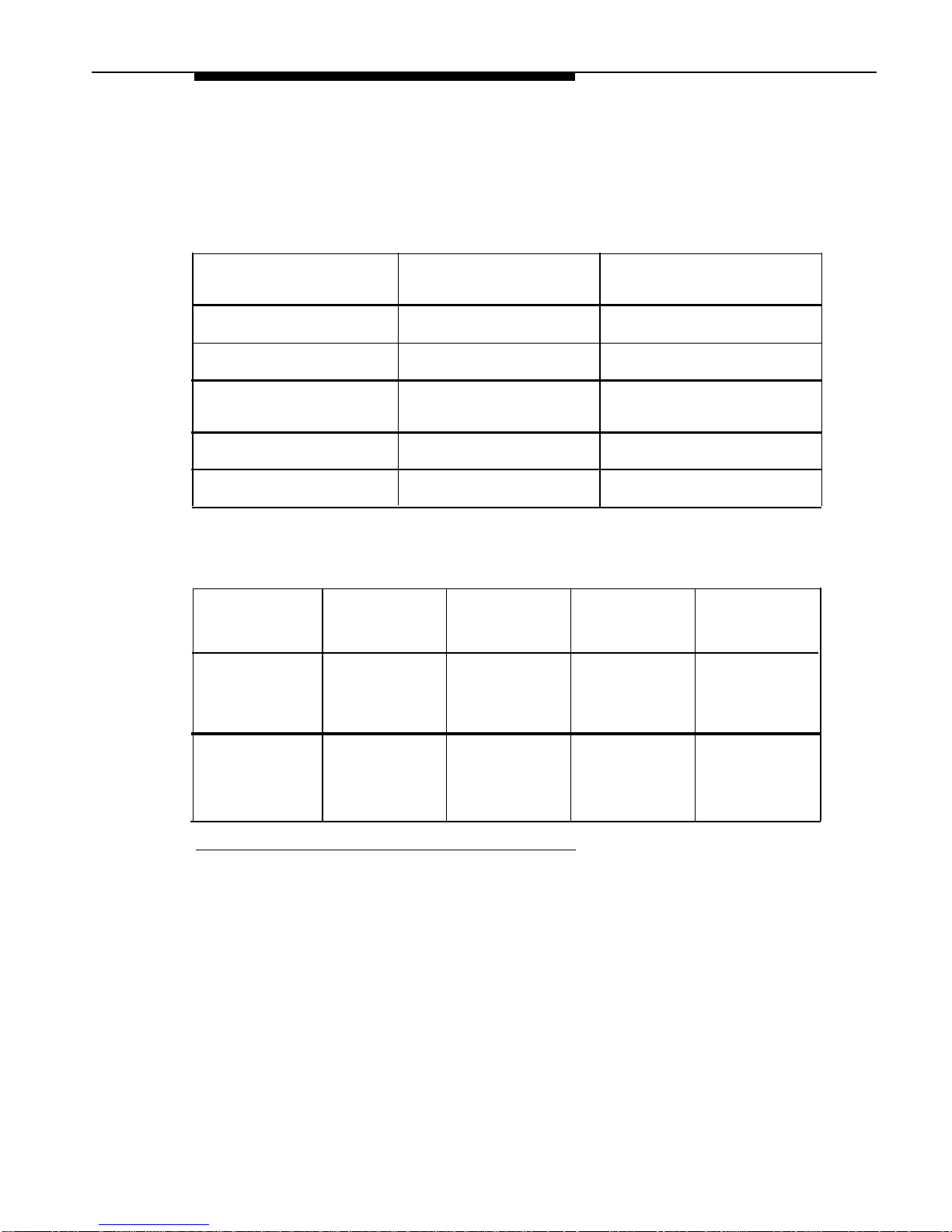
Tables 2-1 and 2-2 summarize the available dialing restrictions and permissions,
showing how they can be combined in a variety of ways to customize an
extension’s dialing privileges.
Table 2-1. Settings that Restrict an Extension’s Access to a Specific Line
Type of Restrictions or
Setting for Setting for
Permissions for the
Line Assignment
Line Access Restriction
Extension
(#301)
(#302)
Can receive and place
All outside lines* “not
“No access” for all lines
intercom (inside) calls only
assigned”
Cannot use a specific outside
line
Can only monitor call activity
and pick up held calls on a
specific line
Can only receive calls on a
specific line
Can only place outgoing calls
on a specific line
Outside line “not assigned”
“No access” for that line
Outside line “assigned”
“No access” for that line
Outside line “assigned”
“Incoming only” for that line
Outside line* may be
“Outgoing only” for that line
“assigned”
Table 2-2. Settings that Restrict an Extension’s Dialing Once It Gets an Outside Line
Type of
Restrictions or
Permissions for
the Extension
Setting for
Line
Assignment
(#301)
Can place
intercom and
local calls only
(and can answer
any call)
Outside line*
may be
“assigned”
Can place
intercom, local
and longdistance calls
(and can answer
any call)
Outside line*
may be
“assigned”
Setting for
Line Access
Restriction
(#302)
“No restriction”
“No restriction”
Setting for
Outgoing Call
Restriction
(#401)
Setting for
Disallowed
Phone Number
Lists (#404)
“Local only” Any local
numbers the
extension should
not dial
“No restriction” Any local and
long-distance
numbers the
extension should
not dial
*
If a line is not assigned to the extension, a user can use Direct Line Pickup to access the line. Emergency
numbers, Marked System Speed Dial numbers, Allowed Phone numbers, and numbers dialed using the
System Password override all dialing restrictions if a user has access to an outside line to place the call. If
Forced Account Code Entry is programmed for an extension, the user must enter an account code before
accessing an outside line. If there are entries in the Forced Account Code List, the entered account code
must match an entry on that list.
Programming
2-9
Page 28

Setting Up Groups of Extensions
You can set up four types of extension groups:
■
■
■
■
Pickup Group Extensions (#501) assigns extensions to one of four
Pickup Groups. A Pickup Group lets any user in the system answer
outside calls for any extension in that group.
Calling Group Extensions (#502) assigns extensions to one of four
Calling Groups. A Calling Group lets users ring or page all extensions in
that group simultaneously.
Night Service Group Extensions (#504) assigns extensions to the Night
Service Group. When Night Service is activated at extension 10, calls
ring immediately at Night Service extensions regardless of how they ring
at other times (only the lines assigned to an extension will ring).
Hunt Group Extensions (#505) assigns extensions to one of seven Hunt
Groups. (Hunt Group 7 is used exclusively for the voice messaging
system.) A Hunt Group lets users ring or voice signal the first available
(non-busy) extension in that group. If a ringing call is not answered, the
system tries each available extension in turn until the call is answered. If
a voice-signaled call is not answered, the call does not keep hunting.
Also use Group Call Distribution (#206) to assign outside lines to a Hunt
Group if you want outside calls to ring directly into a group.
Setting Up Auxiliary Equipment
The following programming procedures help you manage auxiliary equipment.
See Chapter 4 for more information on auxiliary equipment configurations or
refer to Chapter 5 for details on using the procedure:
■
■
■
■
■
Fax Machine Extensions (#601) identifies extensions to which fax
machines are connected.
Music on Hold (#602) activates or deactivates the MUSIC ON HOLD jack
on the processor module. When this jack is activated and an audio
source is connected, callers hear recorded music or messages while on
hold. Also, Background Music lets users with system phones (other
than the MLC-6) play the recorded material through their phone’s speaker
when the phone is not in use.
Hotline (#603) identifies hotline extensions, so when a person lifts the
handset of the hotline phone, a predetermined extension automatically
rings.
Doorphone Extension (#604 and #605) identifies extensions to which
doorphones are connected. Doorphone Alert Extensions (#606)
identifies extensions that signal when the doorphone button is pressed.
AA Extensions (#607) identifies extensions to which PARTNER
Attendants are connected. This lets the system notify users with display
phones when they are receiving a call that has been transferred from the
PARTNER Attendant. Also, Transfer Return Extension (#306) lets you
identify the extension to which a call transferred by the PARTNER
Attendant should be routed if the destination extension does not answer.
2-10
Programming
Page 29

■
■
SMDR Record Type (#608) specifies the type of calls that you want to
record for call reporting—either all calls or outgoing calls only. Account
Code Entry lets users specify account codes for outside telephone calls;
if used, the account codes are included on the call report. SMDR Top of
Page (#609) notifies the system that the printer has been aligned to the
top of a new page.
The voice messaging system uses the following procedures:
– Hunt Group Extensions (#505) assigns the extensions associated
with the voice messaging system hardware to Hunt Group 7—the VMS
Hunt Group. (The PARTNER MAIL VS system uses two extensions;
the PARTNER MAIL system uses two or four extensions.)
– Group Call Distribution (#206) assigns lines to the VMS Hunt Group
so calls can ring directly into the voice messaging system and receive
Automated Attendant Service or directly into the voice mailbox of a
specific subscriber.
–
VMS Hunt Delay (#506) determines when outside calls should be
answered by the Automated Attendant Service of the voice messaging
system. You can set the system for either immediate call handling or
delayed call handling. The setting you select is used for both day and
night operation.
–
VMS Hunt Schedule (#507) determines when outside calls should
ring the VMS Hunt Group (always, day only, or night only) depending
on the status of the Night Service Button (#503) at extension 10.
–
Automatic VMS Cover (#310) determines whether or not an
extension’s unanswered intercom and transferred calls are
automatically covered by the voice messaging system.
– Transfer Return Extension (#306) identifies the extension to which a
call transferred by the voice messaging system should be routed if the
destination extension does not answer and does not have voice mail
coverage active. (The transfer return extension for the voice
messaging system is typically extension 10.)
Hospitality Features
The following hospitality features are for special applications, such as the Bed
and Breakfast and Hotel/Motel industries:
■
■
Outgoing Call Restriction Button (#114) lets you program a button on
the system phone at extension 10 to change an extension’s current
Outgoing Call Restriction setting without entering System Programming
mode. For example, after a guest’s departure, a hotel manager can
change the No Restriction setting of the guest room phone to Inside Only
so outside calls cannot be made from the phone after the guest checks
out.
Wake Up Service Button (#115) lets you program a button on the system
phone at extension 10 to be used for scheduling wake-up or reminder
calls for specified system extensions.
Programming
2-11
Page 30

Using System Programming
System Programming changes settings for the system as a whole, or for
individual lines or extensions. You can also use System Programming to set up
dialing restrictions, define groups, or set up auxiliary equipment. Refer to the
filled-out System Planner when you are changing system settings, and be sure
that any changes in programming are recorded there.
The Programming Overlays
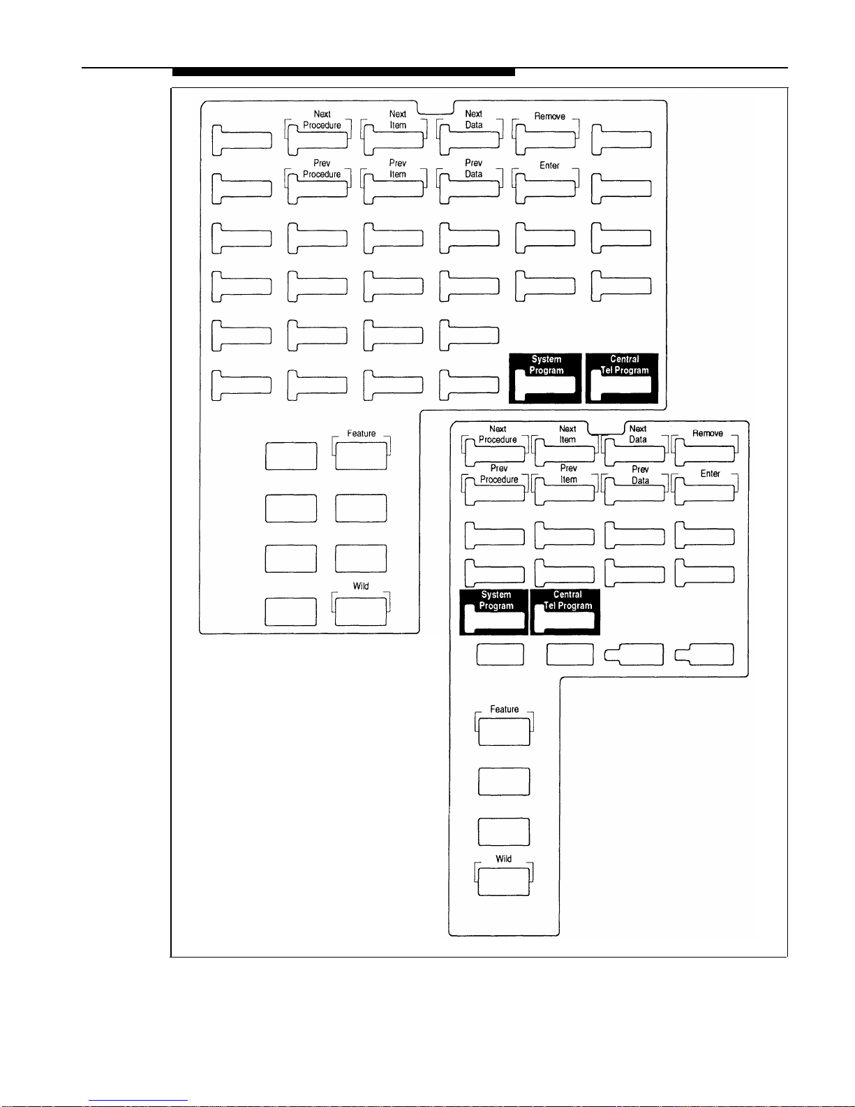
System Programming requires a programming overlay placed over the dial pad
of the MLS-34D, MLS-18D, or MLS-12D system phone at extension 10 or 11.
(Overlays are provided with the system documentation. Replacements can be
ordered through the AT&T Sourcebook.) Figure 2-3 illustrates the programming
overlays.
During System Programming, the normal functions of several buttons on the
display phone at extension 10 or 11 change. For example, the left
Intercom
button becomes System Program , the button used to enter programming mode.
The programming overlay identifies these buttons.
You use the following special buttons while programming:
■
■
■
■
■
■
■
■
■
Next Procedure and Prev Procedure cycle forward and backward through
the programming procedures. You can use these buttons to select a
procedure.
Next Item and Prev Item cycle forward and backward through a
procedure’s parameters. A parameter is typically an outside line, an
extension, or a telephone list entry.
Next Data and Prev Data cycle forward and backward through the valid
entries. These buttons work only for fixed data, such as a line or
extension number. They do not work for variable data such as date, time,
password, telephone numbers, or doorphone assignments.
Remove returns the current setting to the factory setting—or when using
Line Assignment (#301), removes lines from an extension.
Enter ends an entry of variable length, such as a telephone number in an
Allowed Phone Number List.
System Program
starts the System Programming process.
Central Tel Program starts the Centralized Telephone Programming process
(to customize individual telephones centrally from extension 10 or 11).
Feature
when followed by
0 0 ,
enters or exits programming mode.
Wild enters a “wildcard” (a character that matches any digit dialed) in
telephone numbers in Allowed Phone Number Lists (#407), Disallowed
Phone Number Lists (#404), and the Forced Account Code List (#409).
2-12
Programming
Page 31
MLS–34D
MLS-18D/MLS-12D
Figure 2-3.
Programming Overlays for System Display Phones
Programming
2-13
Page 32

Programming Mode
1.
Place the Programming Overlay over the dial pad of the system display phone
at extension 10 or 11—see “The Programming Overlays” earlier in this
chapter for more information.
2.
To enter programming mode, press
Feature
0 0 .
The display reads:
PROGRAM EXT 10
If you are programming from extension 11, “11” displays instead of “10.”
3.
Press
System Program . The display reads:
10 Enter name
This display is for the Extension Name Display feature. When you are
entering System Programming mode, skip it by moving on to Step 4.
4.
Press System Program again. The display reads:
SYSTEM PROGRAM
5. Specify a programming procedure in one of two ways:
■
Direct Method to dial the code for that procedure. System
Programming procedures in this guide are identified by # and a
three-digit code (for example, System Date is #101). This method is
best when you are using only a few procedures during a programming
session and you know the codes.
■
Cycle Method to cycle through the procedures in numerical order.
Press
Next Procedure and Prev Procedure to cycle forward and backward
through the programming procedures. This method is best when you
are using multiple procedures during a programming session, or if you
do not know the codes.
6.
To exit programming mode, you can press
Feature
0 0
or lift the handset
off-hook, then place it back in the cradle.
NOTE:
You can talk on the phone while you program. This is useful if you need to talk
with someone at the AT&T Helpline about programming. However, you must
call before you enter programming mode, and you must use the handset to talk,
not the speaker and microphone.
Changing Programming Type
When you are in programming mode, you can move between System
Programming and Centralized Telephone Programming. To change to
Centralized Telephone Programming when you are in System Programming,
press
Central Tel Program . To move back to System Programming when you are
in Centralized Telephone Programming, press
Central Tel Program
then
System Program
.
2-14
Programming
Page 33

Telephone Programming Options
System telephones are ready to use when they are installed, but they can be
customized to meet the needs of your business and individual users. This
customization is accomplished through Telephone Programming.
Automatic Line Selection
When a user lifts the telephone’s handset or presses
Spkr
,
the system chooses
an idle line automatically. Automatic Line Selection determines the order in
which the system looks for an idle line. You can set the system to look for lines
in any desired order. For standard phones or for any phone used mainly to call
other extensions, select an inside (intercom) line first.
Extension Name on Display
With Extension Name Display, users can assign a name (up to 12 characters
long) to their extension. Then, when those users make an intercom call, group
call, or transfer a call, their name and extension number appears on the display
phone receiving the call. Similarly, users receiving a transfer return call see the
name and extension number of the person assigned to the extension that did
not answer the transferred call.
Line Ringing
Line Ringing defines when each outside line rings at a phone. For each line at
an extension, you can specify Immediate Ring, Delayed Ring (phone rings after
a 20-second delay), or No Ring.
Personal Speed Dialing
Personal Speed Dial numbers are outside phone numbers that a user dials by
pressing
Feature (or # on a standard phone) plus a two-digit code. Unlike
System Speed Dial numbers, which are available to all users in the system,
Personal Speed Dial numbers are available only at the extension for which they
are programmed. Users can store up to 20 Personal Speed Dial numbers.
Programming Telephone Buttons
Telephone buttons without lines assigned to them can be programmed for
system features such as Exclusive Hold or Conference Drop or for telephone
numbers, so you can use the feature or dial the phone number with one touch.
Once programmed, these buttons are called Auto Dial buttons, because simply
pressing the button automatically dials the feature code or the telephone
number.
A user who has a system phone with programmable buttons should consider
programming them with a combination of frequently used features and outside
and intercom telephone numbers.
Programming
2-15
Page 34

Programming a Receptionist’s Extension
Call Handling Options
If you set up a centralized telephone answering position at extension 10, use the
following settings to customize it:
■
■
■
Immediate Call Answering. If the receptionist should answer all calls,
use Line Assignment (#301) to assign all lines to extension 10. Set Line
Ringing for all lines at extension 10 to Immediate Ring; set the lines
assigned at each user’s extension to Delayed Ring or No Ring.
Backup Call Answering. If the receptionist should answer some lines
only when a user does not pick up, set Line Ringing for those lines at
extension 10 to Delayed Ring; set the lines assigned at each user’s
extension to Immediate Ring.
No Answering. If some lines should not be picked up by the receptionist
at all, either set Line Ringing for those lines at extension 10 to No Ring or
simply use Line Assignment (#301) to remove those lines from extension
10. In either case, set Line Access Restriction (#302) to No Access for
those lines at extension 10 to prevent the receptionist from using Direct
Line Pickup to access those lines.
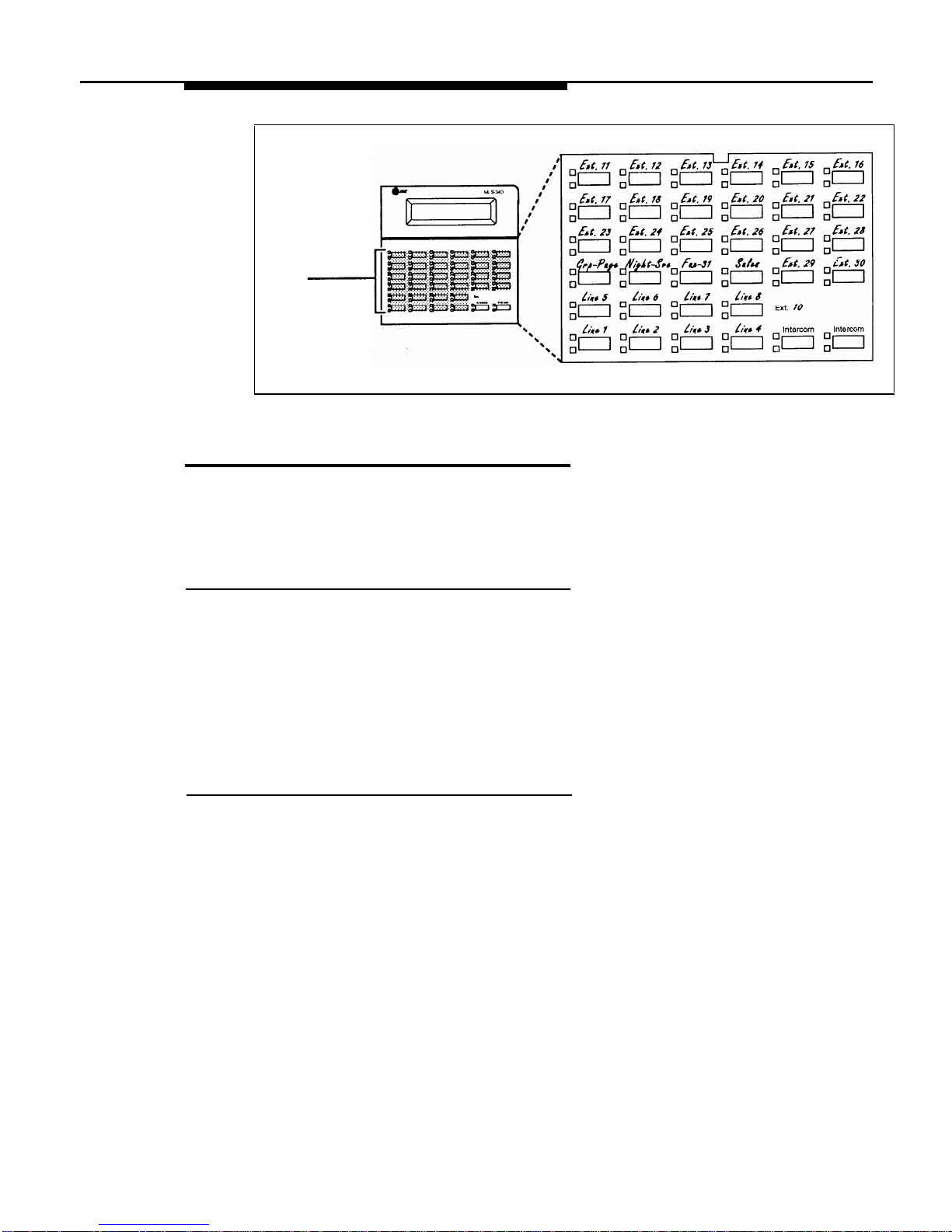
Button Programming
The MLS-34D phone shown in Figure 2-4 illustrates the following programmed
buttons in addition to some other system features:
■
■
Extension Numbers. Auto Dial buttons are programmed for extensions
11 through 30, starting with the top left button shown in Figure 2-4. The
receptionist can use these buttons to dial or transfer calls to the
extensions with one touch. In addition, the lights of the Auto Dial button
show the status of the extension, so the receptionist can tell whether the
phone at the extension is idle (no lights on), busy (red on), calling the
receptionist (green flash), or ringing back after the receptionist
transferred a call (green flutter).
Fax Management. A button (labeled Fax-31) is programmed as a Fax
Management button for the fax machine connected to extension 31. The
lights next to the button show what is happening at the fax machine (for
example, red broken flutter indicates that the fax machine is not
responding—like when it is out of paper). (For more information, see “Fax
Management Feature” in Chapter 4.)
Alternatively, the receptionist can use an MLS-CA24 Intercom Autodialer for the
extensions the receptionist dials most frequently. This leaves buttons on the
phone free for more features and phone numbers.
2-16
Programming
Page 35
MLS-34D
Phone
Line/
Programmable
Buttons
Any unused
line button is
programmable
Figure 2-4.
Button Programming for Receptionist’s Phone
Using Telephone Programming
There are two ways to program a telephone: Centralized Telephone
Programming from extension 10 or 11 (see below) and Extension Programming
from a user’s own extension (see page 2-20).
Telephone Models
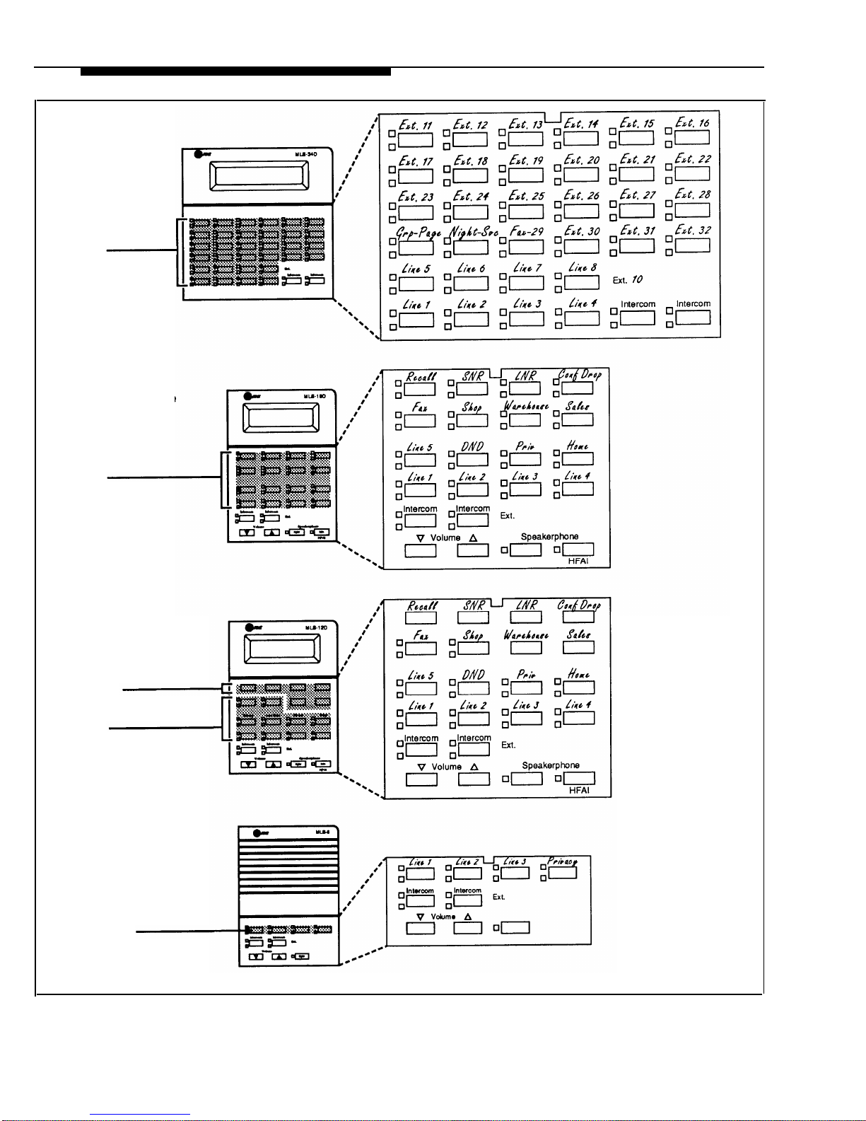
Figure 2-5 illustrates an MLS-34D, MLS-18D, MLS-12D/MLS-12, and MLS-6
phone. As you program buttons, mark their functions on the phone’s labeling
sheet (see the examples in Figure 2-5).
NOTE:
An MLS-6 phone with 4 lines assigned to it has no buttons available for
programming. The MLC-6 cordless phone looks just like an MLS-6 phone when
you program it centrally.
Using Centralized Telephone Programming
Use Centralized Telephone Programming to program features or store
telephone numbers for individual extensions from extension 10 or 11. Most
features also can be programmed on a system phone at the user’s extension.
Keep in mind the following exceptions:
■
■
■
Automatic Line Selection and Line Ringing always must be
programmed using Centralized Telephone Programming.
If a user has a standard phone, Personal Speed Dial Numbers for the
extension can be programmed only by using Centralized Telephone
Programming.
If a user has a standard phone or a non-display system phone,
Extension Name Display for the extension can be programmed only by
using Centralized Telephone Programming.
Programming
2-17
Page 36

During Centralized Telephone Programming, the display phone at extension 10
or 11 takes on the characteristics of the telephone being programmed, including
any System Programming settings and lines assigned to the phone. Make sure
the programming phone is as large as the largest phone in the system, because
an MLS-18D phone cannot program an MLS-34D phone and an MLS-12D
phone cannot program an MLS-18D phone or an MLS-34D phone.
To program a phone from extension 10 or 11, use the following procedure:
1.
2.
3.
4.
Place the Programming Overlay over the dial pad of the system display phone
at extension 10 or 11—see “The Programming Overlays” earlier in this
chapter for more information.
To start programming:
a.
b.
c.
d.
Press
Feature
0 0 .
The display reads:
PROGRAM EXT 10
If you are programming from extension 11, “11” displays instead of “10.”
Press
System Program . The display reads:
10 Enter name
This display is for the Extension Name Display feature. When you are
entering Centralized Telephone Programming mode, skip it by
moving on to Step 2c.
Press
System Program again. The display reads:
SYSTEM PROGRAM
Press Central Tel Program . The display reads:
CENTRAL TEL PROG
Extension:
Dial the extension number of the telephone to be programmed.
Buttons on which lines are assigned for the extension light up to show the
current Line Ringing settings; remaining buttons can be programmed with
telephone numbers, extension numbers, or system features.
At this point, you can:
■
■
■
Use Automatic Line Selection to change the order in which the
telephone tries to select a line when the user picks up the handset.
(If you want to change Automatic Line Selection for an extension, you
must do so immediately after you enter programming mode and dial the
extension number.)
Use Extension Name Display to assign a user’s name to the
extension. (Like Automatic Line Selection, this procedure must be
done immediately after you enter programming mode and dial the
extension number. If you want to change both Automatic Line Selection
and Extension Name Display, first change Automatic Line Selection,
then press
Central Tel Program and return to Step 3, redial the extension
number, then use Extension Name Display.)
Use Line Ringing to change the ringing for an individual line.
2-18
Programming
Page 37
MLS-34D
Phone
Line/
Programmable
Buttons
Any unused
line button is
programmable
MLS-18D Phone
Line/
Programmable
Buttons
Any unused
line button is
programmable
MLS-12D/MLS-12
Phone (display on
MLS-12D only)
Programmable
Buttons
(without lights)
Line/
Programmable
Buttons
Any unused
line button is
programmable
MLS-6 Phone
Line/
Programmable
Buttons
Any unused
line button is
programmable
Figure 2-5. Programmable Buttons and Labeling Sheets on System Phones
Programming
2-19
Page 38

5.
6.
7.
Program Personal Speed Dial Numbers, Auto Dial numbers, or system
features as described in Chapter 5.
To erase the current programming from a button, press the button, then
press
Mic
.
To change the settings for another extension, press Central Tel Program , then
dial the new extension number.
To exit programming mode, you can press
Feature
0 0 ,
or lift the handset
off-hook, then place it back in the cradle.
Changing Programming Type
When you are in programming mode, you can move between System
Programming and Centralized Telephone Programming. To change to System
Programming when you are in Centralized Telephone Programming, press
Central Tel Program then System Program . To move back to Centralized Telephone
Programming when you are in System Programming, press
Central Tel Program .
Using Extension Programming
Users can program features or store numbers on buttons from their own phones
using Extension Programming. Keep in mind the following exceptions:
■
■
■
Automatic Line Selection and Line Ringing always must be
programmed using Centralized Telephone Programming.
If a user has a standard phone, Personal Speed Dial Numbers for the
extension can be programmed only by using Centralized Telephone
Programming.
If a user has a standard phone or a non-display system phone,
Extension Name Display for the extension can be programmed only by
using Centralized Telephone Programming.
To program at the extension, use the following procedure:
1.
2.
3.
4.
To start programming, dial
Feature
0 0 .
Buttons on which lines are assigned for the extension light up to show the
current Line Ringing settings. Remaining buttons can be programmed
with telephone numbers, extension numbers, or system features.
To assign a name to the extension, press left
Intercom
,
then enter the
character codes. See Extension Name Display in Chapter 5 for the
codes.
Program Personal Speed Dial Numbers, Auto Dial numbers, or system
features as described in Chapter 5.
To erase the current programming from a button, press the button, then
press
Mic
.
To exit programming mode, you can press
Feature
0 0 ,
or lift the handset
off-hook, then place it back in the cradle.
2-20
Programming
Page 39

Learning About Telephones
3
Contents
System Telephones
■ Buttons and Indicators
■
Lights
■
Ringing Patterns
■
Dial Tones
■ Using the Handset, Speaker, and Microphone
Hands-Free Answer on Intercom (HFAI)
Voice Interrupt on Busy Calls
Speakerphone Performance Tips
Standard Telephones
■
Ringing Patterns
■
Dial Tones
■ Using the Switchhook
■
Limitations
■
Feature Phones
Combination Extensions
Using Telephones
■ Basic Call Handling Features
■ Dial-Code Features
3-1
3-2
3-4
3-5
3-5
3-5
3-6
3-7
3-7
3-7
3-8
3-9
3-9
3-9
3-10
3-10
3-11
3-11
3-12
3-i
Page 40

Learning About Telephones
3
This chapter explains how system and standard phones work with the system,
as well as combination extensions where more than one phone or standard
device is installed. System phones are described first, followed by standard
phones on page 3-7 and combination extensions on page 3-10. In addition, call
handling features are listed on page 3-11. See the feature name in Chapter 5
for details on a specific feature.
System Telephones
System phones, which include the MLS-34D, MLS-18D, MLS-12D, MLS-12,
MLS-6, and MLC-6 models, have several buttons and indicators in common.
The following pages explain where they are and how they work.
Learning About Telephones
3-1
Page 41
Buttons and Indicators
MLS-34D
Display
MLS-18D
Programmable Buttons
Display (not on MLS-12)
(6 without lights)
Line/Programmable
Buttons
Intercom Buttons
(2)
Line/Programmable
Buttons
(32 with lights)
Intercom Buttons (2)
MLS-12D/MLS-12
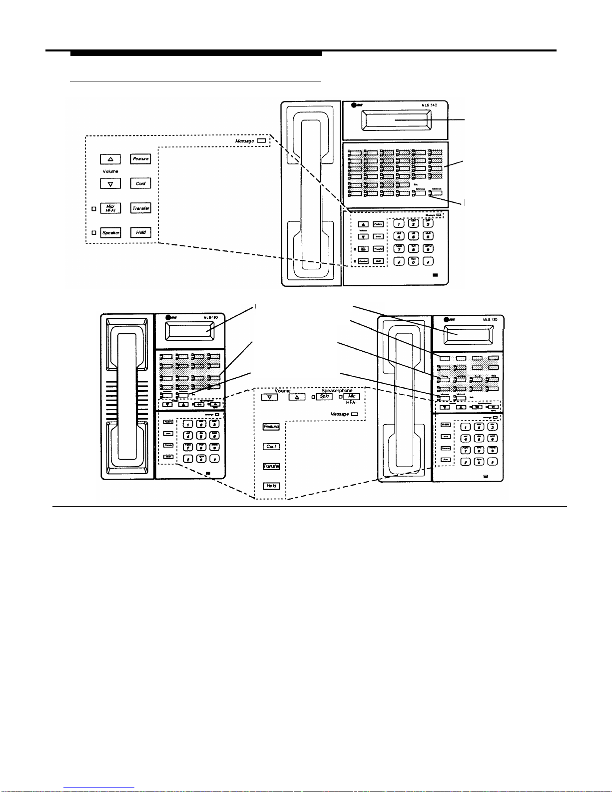
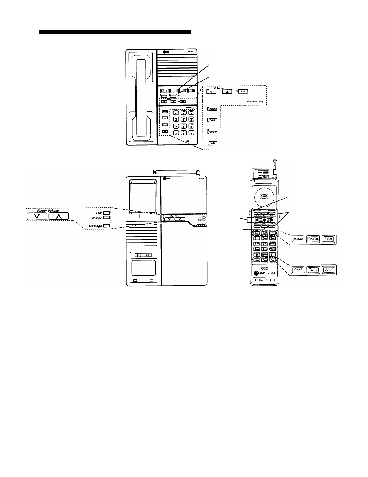
The following buttons and indicators appear on system phones:
Display.
(MLS-34D, MLS-18D, and MLS-12D only) Shows date, day, and time when phone is idle, number dialed when placing
a call, extension number (and name if programmed) calling you or transferring a call to you, and duration while a call is in
progress. When programming, shows settings, options, and prompts. (To adjust the MLS-18D display contrast, see Volume
Control Buttons.)
Line/Programmable Buttons. Used for outside lines or (if no line is assigned on a button) for programming telephone or
extension numbers, or other system features (such as Last Number Redial). When a line is assigned, you can press the line button
to make a call on a specific line (lights show status of line). When a number or feature is programmed, you can press the button
to dial the number or use the feature. The MLS-34D has 32 programmable buttons (all with lights); the MLS-18D has 16
programmable buttons (all with lights); the MLS-12D and MLS-12 have16 programmable buttons (10 with lights); the MLS-6 and
MLC-6 phones have 4 programmable buttons (all with lights).
Intercom Buttons. Press to make (or answer) a call to (or from) another extension in the system.
Other Buttons and Indicators (shown in exploded views)
Feature (labeled “Feat” on MLC-6). Press to change programmed settings or use system features.
Conf. Press to add other parties to your call.
Transfer (labeled “Trans” on MLC-6). Press to pass a call to another extension.
Hold. Press to put a call on hold.
3-2
Learning About Telephones
Page 42
MLS-6
MLC-6 (Base)
Line/Programmable
Buttons (4)
Intercom Buttons (2)
MLC-6 (Handset)
Earpiece Volume
Control Switch
Line/Programmable
Buttons (4)
Handset
Display
Intercom
Buttons (2)
Spkr (all models except the MLC-6). Press to turn on and off speaker and microphone (if available), so you can dial and have a
conversation without lifting the handset. The light next to this button shows when the speaker is turned on.
Mic (MLS-34D, MLS-18D, MLS-12D, and MLS-12 only). Press to turn the microphone on and off. The light next to this button shows
when the microphone is turned on. Leave on to use the Hands-Free Answer on Intercom (HFAI) feature.
Message Light.
Lights when someone signals you with the Message Light On feature, or if you have a voice messaging system, when
you have a message in your mailbox.
Volume Control Buttons. (all models except the MLC-6). Press ▼ to decrease or ▲ to increase the volume as follows:
■
To adjust ringer volume, press ▼ or ▲ while the phone is idle and the handset is in the cradle.
■
To adjust speaker volume, press ▼ or ▲ while listening to a call through the speaker.
■
To adjust handset volume, press ▼ or ▲ while listening through the handset.
■ To adjust background music volume, press ▼ or ▲ while listening to music through the phone’s speaker.
To adjust the display contrast on the MLS-18D phone, press
★
then ▼ to decrease the brightness or ▲ to increase the brightness,
while the phone is idle and the handset is in the cradle.
On/Off Button (MLC-6 Handset). Turns the handset on and off. (You must turn the handset on to make calls.)
Status Button (MLC-6 Handset). Quickly updates the display on the MLC-6 handset.
Earpiece Volume Control Switch (MLC-6 Handset). To adjust handset volume, slide switch up (high) or down (low).
Talk indicator (MLC-6 Base). Lights when handset is lifted and turned on.
Charge indicator (MLC-6 Base). Lights when handset is placed on the base and handset batteries are charging.
Ringer Volume Control (MLC-6 Base). To adjust volume, press ▼ or ▲ while the phone is idle.
Learning About Telephones
3-3
Page 43
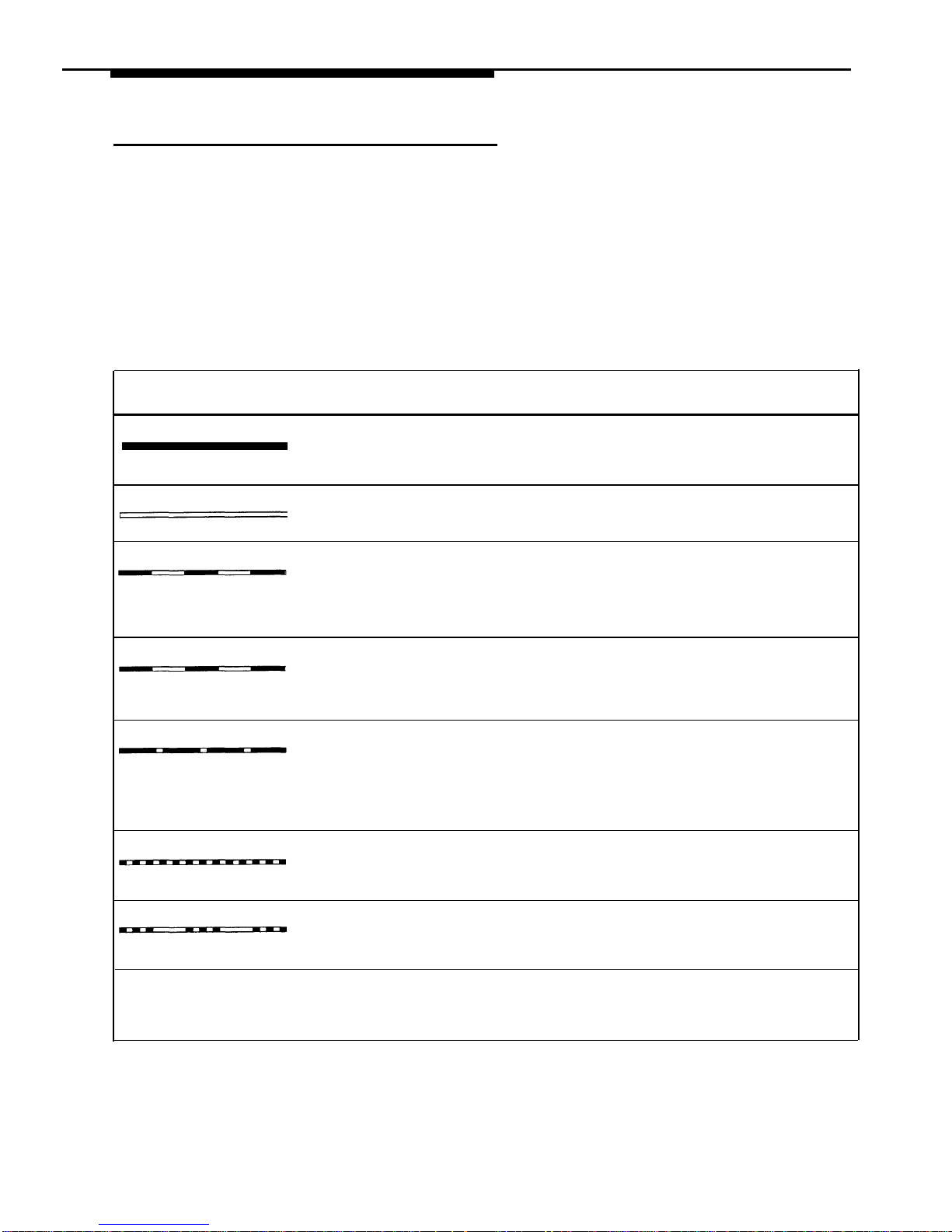
Lights
Each line button has a green light and a red light. The meaning of these lights
varies, depending on whether a button is used to access an outside line, is
programmed with a system feature, or is programmed for Auto Dialing an
extension number (Intercom Auto Dial button). (Auto Dial buttons for fax
extensions show additional information; these “Fax Management” buttons are
described in Chapter 4. When a phone is in programming mode, the lights
show information about programmed settings; See Chapter 2 for details.)
Table 3-1 shows the meanings of the various light patterns for each possible
button assignment.
Table 3-1. Light Patterns for System Phones
Feature Button
Intercom Auto Dial
Light Pattern
Line Button
Steady On
Line is busy. Green means
Green means Red means the extension
your phone is busy; red means
feature* is on
is busy (making or
someone at another extension
answering a call).
is busy on the line.
Off
Line is idle (not being used).
Feature* is off Extension is idle (not
being used).
(steady off)
Flash
A call is ringing on the line. —
Green flash means
Green flash means a call is
(long on, long off)
someone at another
ringing at your extension. Red
extension is calling you.
flash means a call is ringing on
the line, but not at your
extension.
Alternating Red/Green Flash
Alternating green and red flash
—
—
appears at both extensions in a
(red on, green on, red on,
joined call, and at any
green on)
extension connected in a
conference call.
Wink
A call on the line is on hold. —
—
Green wink means the call is
(long on, short off)
on hold at your extension. Red
wink means the call is on hold
at another extension. (Anyone who has the line can
retrieve the call.)
Green Flutter
A call is on exclusive hold at
A Wake Up
A call transferred to the
your extension (and can only
Service call is
(short on, short off)
extension is now returning
be retrieved from your
being scheduled
to your phone.
extension).
from extension 10
Red Broken Flutter
—
—
Fax Management only—
(short on/off, long off)
the fax extension is not
answering calls (may be
out of paper).
*
Applies to Do Not Disturb, Night Service, Outgoing Call Restriction Button, Privacy, Voice Interrupt on Busy
Talk-Back, and VMS Cover, all of which require programming on a button with lights. Can also apply to Account
Code Entry, Background Music, and Call Forwarding/Call Follow-Me, if any of them are programmed on a button
with lights. (For more information about programming these features, see Chapter 5.)
3-4 Learning About Telephones
Page 44

Ringing Patterns
System phones have these ringing patterns:
■ An outside call will ring . . . ring . . . ring.
■ An intercom call will ring BEEP. . . ring BEEP. . . ring BEEP. If you have
a system display phone, the caller’s extension number (and name if
programmed) will show on the display.
■
A transferred call, or an unanswered transferred call that is ringing back
at your extension, will ring BEEP BEEP. . . ring BEEP BEEP. . . ring BEEP
BEEP.
NOTE:
If you use the system with PBX or Centrex lines, the PBX/Centrex distinctive
ringing patterns are not passed to phones. Phones use the ringing patterns
described here instead.
Dial Tones
You will encounter two different dial tones when calling with a system phone:
■
■
Outside dial tone is generated by your local phone company to indicate
that you are connected with an outside line.
Intercom dial tone is generated by the system to indicate that you are
connected with an inside line. You hear this dial tone when you are
making an inside, or intercom, call.
To hear the difference between the two types of dial tones on a system phone,
press a line button. The dial tone you hear is an outside dial tone. To hear an
intercom dial tone, press
Intercom
.
Using the Handset, Speaker, and Microphone
Every system phone (except the MLC-6 phone) has a speaker, which you can
turn on by pressing
Spkr
.
When the green light next to
Spkr
is on, the speaker
is on.
MLS-34D, MLS-18D, MLS-12D, and MLS-12 phones also have a microphone.
On these phones, pressing
Spkr
turns on both the speaker and the
microphone. In addition, you can turn just the microphone on and off by
pressing
Mic
.
When the green light next to
Mic
is on, the microphone is on.
Learning About Telephones
3-5
Page 45

If you prefer to dial and conduct calls without lifting the handset, you can use
the speaker and the microphone instead. Use these techniques to make calls
with the speaker and the microphone (if you have one):
■
■
■
■
To make a call without lifting the handset, press Spkr to get a dial tone;
then dial the number and you will hear the call ringing. When the other
party answers, you can talk without lifting the handset. On MLS-6 phones
(which have no microphone), you must lift the handset to talk when the
other party answers. You cannot listen through the handset and the
phone’s speaker at the same time.
To turn off the microphone when you are using the speaker, press
Mic .
This will mute your voice so the other party cannot hear you.
If you are already on a call, you can switch from the handset to the
speaker and microphone (on an MLS-34D, MLS-18D, MLS-12D, or
MLS-12 phone) by pressing
Spkr and hanging up the handset.
Conversely, if you are using the speaker and microphone and want to
switch to the handset, lift the handset and the speaker and microphone
will turn off.
Use the Hands-Free Answer on Intercom (HFAI) feature to answer
voice-signaled calls without lifting the handset (see below).
Hands-Free Answer on Intercom (HFAI)
When you receive a voice-signaled intercom call, your phone beeps once to
indicate that your speaker has been turned on automatically, and you hear the
caller’s voice over your phone’s speaker. If you leave your microphone on all
the time, you can start talking when you hear the caller, without lifting the
handset. This feature is called Hands-Free Answer on Intercom.
NOTE:
Since MLS-6 phones do not have microphones, you must lift the handset to
answer voice-signaled calls to those phones.
Any user in the system can make a voice-signaled call to an idle MLS-model
system phone by pressing
Intercom
✳
and then dialing an extension number
or pressing an Auto Dial button programmed for voice signaling. (You can
make a voice-signaled call from either a system phone or a standard phone.
However, if you try to make a voice-signaled call to a standard phone or MLC-6
phone, it will ring.)
NOTES:
1.
The HFAI feature can be turned on or off only when your phone is idle. Muting
your voice while you are on a call only turns off the microphone for the duration
of the call.
2. If HFAI is on and you are already on a call, you will not hear any other voice
signals to your extension.
3.
If you make a voice-signaled intercom call to a busy extension, you may
initiate a voice interrupt on busy call to that extension. See “Voice Interrupt On
Busy Calls” on the next page for more information.
3-6
Learning About Telephones
Page 46

Voice Interrupt on Busy Calls
A voice interrupt on busy call is a special intercom call that lets you interrupt
and speak to another user who is busy on a call and who has the Voice
Interrupt On Busy feature (#312) activated for that user’s phone. When you
use Voice Interrupt on Busy to interrupt another user on a call, the interrupted
user hears two beeps before hearing your voice. Be aware that the third party
to whom the interrupted user is speaking will probably hear the two beeps and
the faint sound of your voice. Therefore, the message you deliver with the
interruption should be brief and discreet. If the interrupted user wants to answer
you, he or she can press a programmed Talk-Back button—the interrupted
user’s response cannot be heard by the third party in this case.
Speakerphone Performance Tips
The speaker on your MLS-34D, MLS-18D, MLS-12D, or MLS-12 telephone has a
sensitive sound-activated switch. Room acoustics and background noise can
affect the proper operation of the speakerphone. To ensure that your
speakerphone works effectively, follow these guidelines:
■
■
■
■
■
■
■
■
Avoid placing your phone in areas with high background noise caused by
loud voices, radios, printers, copiers, typewriters, other noisy office
equipment, and heater and air conditioning fans.
Avoid rustling papers near the microphone (lower right corner of your
phone).
Avoid talking before the other person is finished speaking. When you
both talk at the same time, only one person’s voice comes through.
Do not use your speaker to make announcements over a loudspeaker
paging system connected to your phone system.
When talking, always face your phone and stay within two feet of it.
Place your phone at least six inches away from the edge of your desk.
If you have difficulty hearing the other party, try increasing the speaker
volume. If you have background noise, try turning off the microphone
when the party at the other end is speaking and turning it on when you
speak. If the difficulty persists, lift your handset to continue the
conversation.
In conference rooms, a separate speakerphone (such as the AT&T S203
Speakerphone) is recommended, since the built-in speaker on a system
phone is designed for individual use.
Standard Telephones
In addition to system phones, you can connect industry-standard touch-tone or
rotary dial phones—and even some feature phones (which have built-in calling
features)—directly to the system. You can also combine standard phones on
the same extension with system phones or other devices, without using
expensive adapters or connectors.
Learning About Telephones
3-7
Page 47

Standard phones can do many of the things that system phones can do, and
you can save money by using them in certain situations when a system
telephone is not needed. Follow these guidelines when using standard phones:
■
■
■
■
■
Use standard phones as power failure backups. In the event of a power
failure, standard phones at extensions 10, 16, 22, and 28 connect to lines
1, 3, 5, and 7, respectively, for continued operation; but system phones
will not work. You can connect standard phones in combination with
system phones at power failure extensions, or you can simply keep spare
standard phones at those extensions to serve as replacements in case of
a power failure.
To use a system feature, press
#
(in place of
Feature
used on system
phones) followed by its two-digit code when you hear intercom dial tone.
For features that use
Intercom on system phones, dial only the two-digit
code when you hear intercom dial tone. (Instructions for using these
features on standard phones are included in Chapter 5, “Feature
Reference.”)
To use a Speed Dial number, press
# followed by its two-digit code
when you hear intercom dial tone. (For details, see “System Speed Dial
Numbers” and “Personal Speed Dial Numbers” in Chapter 5.)
Use the switchhook on a standard phone to place calls on hold, transfer a
call, or set up a conference call. (For details, see “Using the Switchhook”
on the next page, or “Hold,” “Transferring Calls,” and “Conference Calls”
in Chapter 5.)
If the standard phone has a message waiting light, use it to notify users of
messages. (For details, see “Message Light On” and “Message Light
Off” in Chapter 5. For a list of supported phones, see “Standard
Telephones” in Chapter 1.) Alternatively, if you have a voice messaging
system, the light is used to indicate that a message has been left in your
mailbox. On a standard phone, the message light flashes when the
phone is idle to indicate that the extension has received a message.
Ringing Patterns
Standard phones have these ringing patterns:
■ An outside call will ring . . . ring . . . ring.
■ An intercom call will ring-ring . . . ring-ring . . . ring-ring.
■ A transferred call, or an unanswered transferred call that is ringing back,
will ring-ring-ring . . . ring-ring-ring . . . ring-ring-ring.
NOTE:
If you use the system with PBX or Centrex lines, the PBX/Centrex distinctive
ringing patterns are not passed to phones. Telephones use the ringing patterns
described here instead.
3-8 Learning About Telephones
Page 48

Dial Tones
Standard phones have two different dial tones:
■
■
Outside dial tone is generated by your local telephone company to
indicate that you are connected with an outside line.
Intercom dial tone is generated by the system to indicate that you are
connected with an inside line. You hear this dial tone when you are
making an inside, or intercom, call.
To hear the difference between the two dial tones, lift the handset. The dial tone
you hear (assuming the phone is set to select intercom first, as recommended in
this guide) is an intercom dial tone. To hear an outside dial tone, press
9 .
Using the Switchhook
Some of the call handling instructions in this guide direct you to “rapidly press
and release the switchhook.” Pressing the switchhook for 1/4 to 1 second sends
a signal over the line called a switchhook flash. However, do not press the
switchhook too quickly. If you press the switchhook and nothing happens, try
again and press it a little longer.
NOTE:
If your feature phone has a button labeled “Recall” or “Flash,” use the button
instead of pressing the switchhook. If you use the system with PBX or Centrex
lines, your PBX or Centrex documentation may tell you to press the switchhook
to access PBX or Centrex features. Use the Recall feature instead (see “Recall”
in Chapter 5).
Limitations
Because standard phones do not have system line buttons, feature buttons, or
dedicated function buttons, basic call handling procedures are sometimes
different from those for system telephones. In addition, the following actions
cannot be performed at a standard telephone:
■
■
■
■
■
You cannot enter programming mode.
Because there are no line buttons on standard phones, users must use
Direct Line Pickup—idle Line to select a specific line; otherwise, the
system selects an idle line automatically when the user dials a 9 at
intercom dial tone. (For information on Automatic Line Selection, see
Chapter 5.)
If a standard phone is in use, there is no indication of a second call and
an inside caller will hear a busy tone.
Users can make a voice-signaled call from a standard phone, but if users
try to make a voice-signaled call to a standard phone, it will ring because
the standard phone does not have a system speaker.
Users cannot use the
System Password.
Learning About Telephones
3-9
Page 49

■
■
Users cannot access the following system features: Account Code
Entry, Background Music, Do Not Disturb, Exclusive Hold, Privacy,
Save Number Redial, VMS Cover, Voice Interrupt on Busy, Voice
Interrupt on Busy Talk-Back, and Voice Mailbox Transfer.
Do not use Forced Account Code Entry with a standard phone,
because the phone will bot be able to get dial tone and make calls.
Feature Phones
A feature phone is a standard telephone that has feature buttons in addition to
the regular 12-key dial pad. For example, there are feature phones that have
programmable auto dial buttons, last number redial buttons, hold buttons, and
built-in speakers. Even though some feature phones have buttons like those
provided on system phones, they may not work. Refer to the feature phone’s
documentation for more information on what these phones can do.
Combination Extensions
A combination extension is an extension with two devices connected to
it—either two standard devices, or a system phone and a standard device (but
not two system phones). (For instructions on how to install a combination
extension, see the PARTNER Plus Communications System Installation guide.)
The following are examples of useful combination extensions:
■ System phone plus standard telephone, for power failure backup on
extensions 10, 16, 22, and 28
■
System phone plus answering machine
■
System phone plus fax machine
■
System phone plus headset
■
System phone plus an external alert (such as a bell or chime).
Using the telephones in a combination extension is fairly simple. The main thing
to understand is that the two telephones share a single extension in the same
way several home telephones share a single line. A system telephone works
like it always does and a standard telephone works like it always does when
connected to the system. Only one phone or device can be used at a time,
unless you want to join the two on a single call (the same way two people can
pick up the same call on different telephones at home). For example:
■
■
■
■
■
Both phones share the same extension number.
Both phones share the same voicepath, that is, when either phone is
busy, the extension is busy.
Calls ring at both phones.
A second call can ring at the system phone while the standard phone is
busy, but do not use the system phone to answer the second call until the
standard phone is idle or the first call will be disconnected.
If you make a voice-signaled intercom call to a combination extension
with a system phone, only the system phone signals.
3-10
Learning About Telephones
Page 50

■
■
■
■
■
The lights on the system phone show what the standard telephone is
doing as well as what the system phone is doing. For an explanation of
light patterns, see “Lights” at the beginning of this chapter.
If Privacy is active at a combination extension, no other extension can
join a call in progress at either a system phone or a standard device.
(However, a phone can interrupt a call on a standard device at the same
extension. For example, if a system phone and modem are combined at
an extension, picking up the handset of the system phone could interrupt
a modem transmission, even if Privacy is active.)
While on a call on a standard phone, you can use the system phone’s
dial-pad and fixed-feature buttons to handle calls. For example, you can
use the system phone to select a specific outside line, and conduct the
call on the standard phone. Or, if someone is on a call using the
standard phone, someone else can put that call on hold by pressing
Hold on the system phone. To do this, it is not necessary to lift the
handset of the system phone. Held calls do not ring at a standard phone
in a combination extension. To retrieve a held call from the standard
phone, use Direct Line Pickup—Active Line.
A standard phone’s message waiting light will not light if Background
Music is playing through the system phone’s speaker.
The ringer equivalence number (REN) of a standard device or the
combined REN of two devices cannot be greater than 2.0. (The REN of a
system phone is 0.0.)
Using Telephones
Your system provides intuitive operation of basic call handling features, plus
dial-code features that make it easy for users to handle calls flexibly and
efficiently from both system and standard phones. For more information on a
specific feature, refer to the feature name in Chapter 5.
Basic Call Handling Features
The following features are available from both system and standard phones:
■
Making Calls
■ Answering Calls
■
Hold (placing a call on hold)
■
Transferring Calls (passing a call to another system extension)
■ Conference Calls (making a conference call)
■
Joining Calls
Learning About Telephones
3-11
Page 51

Dial-Code Features
Dial-code features are features that you access by dialing a feature code at the
telephone keypad. From a system phone, you can dial
Feature or Intercom ,
followed by the two-digit code (or press a programmed Auto Dial button); from a
standard phone, you typically dial
# followed by the two-digit code when you
have intercom dial tone. Some dial-code features are not available on standard
phones, as noted by an asterisk (*) in the following list.
■
■
■
■
■
■
■
■
■
■
■
■
■
■
■
■
■
■
■
■
■
Account Code Entry*
Background Music*
Call Forwarding/Call Follow-Me
Call Pickup
Conference Drop
Direct Line Pickup—Active Line
Direct Line Pickup—Idle Line
Exclusive Hold*
Group Calling—Ring/Page
Group Hunting—Ring/Voice Signal
Group Pickup
Last Number Redial
Loudspeaker Paging
Message Light Off
Message Light On
Personal Speed Dial Numbers
Recall
Save Number Redial*
System Speed Dial Numbers
Touch-Tone Enable
Voice Mailbox Transfer*
*
Available only on system phones.
3-12
Learning About Telephones
Page 52

Using Auxiliary Equipment
4
Contents
Overview
■
If a Device Has Trouble
Answering Machines
■
Single Answering Machine
■
Multiple Answering Machines
■
Personal Answering Machine
Call Reporting Devices (SMDR)
■
Programming
■
Call Reports
■
Considerations
■
Output Format
■
Serial Printers
■
Call Accounting Devices
Credit Card Scanners
Fax Machines
■
Using Fax Machines
Fax Management Feature
Transferring a Call to the Fax Machine
Using the Fax Machine’s Notify Feature
■ Setting Up Fax Machines
Restricting Dialing from a Fax Machine
■
Single Fax Machine
■
Fax Line Saver
■
Send and Receive Fax Machines
Modems
■
Stand-Alone Modem for Placing Calls Only
■
Send and Receive Modem
4-1
4-3
4-4
4-5
4-6
4-7
4-8
4-8
4-9
4-10
4-10
4-10
4-10
4-11
4-12
4-12
4-12
4-13
4-13
4-14
4-14
4-15
4-16
4-17
4-19
4-19
4-20
4-i
Page 53

Contents
Night Service with Auxiliary Equipment
4-21
PARTNER Attendant
4-23
■
Backup for Receptionist
4-23
Voice Messaging Systems
4-24
■
Delayed Call Handling
4-24
4-ii
Page 54

Using Auxiliary Equipment
4
Overview
There are many ways to set up auxiliary equipment—the setup you choose
depends upon your needs and the number of devices you have. This chapter
presents some common setups. (It does not cover how to physically connect
the equipment, or how to program the features. See the PARTNER Plus
Communications System Installation guide for installation instructions, Chapter 5
for programming instructions, and the equipment manufacturer’s documentation
for complete details on the device you connect.)
This chapter shows various applications for the following types of equipment:
■
■
■
■
■
■
■
Answering Machines
Call Reporting Devices
Credit Card Scanners
Fax Machines
Modems
PARTNER Attendant
Voice Messaging Systems
Using Auxiliary Equipment
4-1
Page 55

In addition, you can connect the following devices to your system:
■
■
■
■
■
■
■
Doorphones allow visitors to signal extensions by pressing a button on
the doorphone; the person who answers a doorphone call can then
speak with the visitor at the doorphone. A doorphone is especially useful
for providing access to offices or departments after hours. For example,
you can install a doorphone outside your building entrance to allow
visitors to ring telephones inside the building when the receptionist is not
there and the front door is locked.
The system supports up to two AT&T PARTNER Doorphones or any
number of AT&T Universal Doorphones. Universal Doorphones offer a
door unlock feature and can be installed in addition to PARTNER
Doorphones.
Loudspeaker paging systems allow you to broadcast a message over a
large area, by connecting the paging system directly to the PAGE jack on
the processor module. The system supports all AT&T paging systems
including the entire PagePac® line, and most paging systems from other
manufacturers. In addition to its numerous paging features, the
PARTNER PagePac provides doorspeaker and door unlock capabilities.
For information on how to use a loudspeaker paging system with the
system, see Chapter 5.
PARTNER Passage Way™ Solution
allows you to combine your
Personal Computer (PC) running Microsoft® Windows™ 3.1 with your
phone. You can then use your PC for tasks such as dialing out from an
electronic phone list, logging phone calls, and programming your phone.
Music-on-hold systems allow you to play recorded music or messages
to callers while they are on hold, by connecting the audio source to the
processor module. The system supports the AT&T Magic on Hold system
and most models from other manufacturers. (If you use equipment that
rebroadcasts music or other copyrighted materials, you may be required
to obtain a license from a third party such as ASCAP or BMI.)
Extra alerts help make users aware of incoming calls. For example, you
can use an audible alert (chime, horn, or bell) to replace a phone ring in a
noisy area, such as a factory. Similarly, you can use a visual alert (strobe
or light) to replace a phone ring in a quiet area, such as a library. AT&T
offers several compatible alerts.
Speakerphones provide hands-free two-way operation of a phone
without lifting the handset. Combining a speakerphone with a system
phone or a standard phone in a conference room or office is an
inexpensive way for several people at a meeting to conference in other
parties. (System phone speakers are designed for individual use—not
group use.) The system supports the AT&T S203 speakerphone and any
industry-standard speakerphone.
Headsets allow users to hold hands-free conversations. A headset is a
combination earphone and microphone worn on the head, useful for
receptionists, salespeople, or others who need to have their hands free
while talking on the phone. AT&T offers several compatible headsets.
4-2
Using Auxiliary Equipment
Page 56

■
■
■
■
Specialty Handsets are designed for those individuals who need greater
functionality than that provided by the handsets on system phones and
standard phones. For example, an amplified handset is available for
certain system phones for hard-of-hearing users.
In-Range Out-of-Building (IROB) protectors are required to prevent
electrical surges from damaging your system when phones are installed
in another building, but on the same continuous property. The system
supports the AT&T IROB protector, which provides coverage for up to
3,000 feet (915 meters) for standard phones and 1,000 feet (305 meters)
for system phones.
Electromagnetic Interference (EMI) filters allow you to block “noise”
generated by a nearby radio station, as well as most electrical devices.
Caller ID devices, such as a PC with Caller ID software, support
applications for storing or processing Caller ID information. You can
connect these devices provided you subscribe to the service from your
local phone company and connect the device directly to the Caller ID
line. To install devices, refer to “Connecting Caller ID Devices” in the
PARTNER Plus Communications System Installation guide for details.
Follow the manufacturer’s instructions packaged with the devices. To order
auxiliary equipment, refer to “Product Ordering Information” in Appendix B.
If a Device Has Trouble
Two System Programming procedures can be used to adjust the system
settings for auxiliary equipment installed at an extension, if a device has trouble
answering calls or dialing out. If a device (such as an answering machine) does
not pick up transferred or intercom calls, you can use Distinctive Ring (#308) to
change the ringing, so that all calls ring like outside calls at that extension. If an
autodialing device (such as a modem) has trouble autodialing, use Intercom
Dial Tone (#309) to change the intercom dial tone for the extension to Machine
(outside line) dial tone.
Using Auxiliary Equipment
4-3
Page 57

Answering Machines
You can use an answering machine to answer calls at night when no one is
around, or during business hours when no one can get to the phone. If you
have an AT&T answering machine with the Call Intercept feature, you can pick
up a call that has been answered by the answering machine by joining the call
from any system phone. When you do so, the system sends the answering
machine a signal that makes it hang up.
The following are ways you can connect answering machines to your system:
■
■
■
Single answering machine. This basic setup can cover all the lines in
the system. Anyone on the system can call the machine to retrieve
messages.
Multiple answering machines. If you get too many calls for one
machine to cover, connect two or more machines to cover all calls.
Personal answering machine. An answering machine can share an
extension with a phone to answer calls to the extension.
NOTE:
If you have an answering machine and a system phone on the same extension,
the answering machine will be able to answer calls only when the phone is idle.
4-4
Using Auxiliary Equipment
Page 58
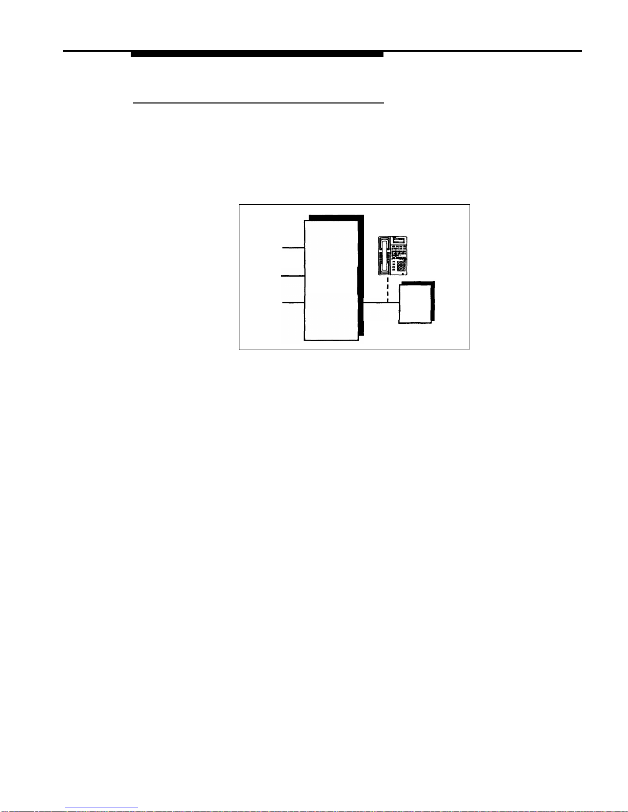
Single Answering Machine
The single answering machine setup (Figure 4-1) serves the entire system. The
answering machine is connected to its own extension, and can cover all the
lines in the system, or as many lines as you assign to it. You can install the
answering machine on an extension by itself, or combine it with a system phone
or a standard phone on the same extension (see “Combination Extensions” in
the PARTNER Plus Communications System Installation guide).
Telephone
(optional)
CONTROL
UNIT
Lines
Ext X
ANS
MACH
Figure 4-1. Single Answering Machine
To Use
■
Go to the machine to manually play back messages.
■
■
From any system extension, make an intercom call to the answering
machine extension. When the machine answers, dial its message retrieval
code.
From outside the system, call in on any line assigned to the machine.
When the machine answers, dial its message retrieval code.
To Program
1.
2.
3.
4.
Using Auxiliary Equipment
4-5
Set Line Ringing for all lines assigned to extension X to Immediate Ring.
Use Line Assignment (#301) to assign all the lines to extension X that you
want the answering machine to cover.
Make sure extension X is not assigned as a Pickup Group Extension (#501),
Calling Group Extension (#502), Night Service Group Extension (#504),
or Hunt Group Extension (#505).
Adjust the answering machine to answer according to your needs. For
example, set the machine to answer on the fourth ring during the day so
someone has a chance to pick up the call.
Page 59
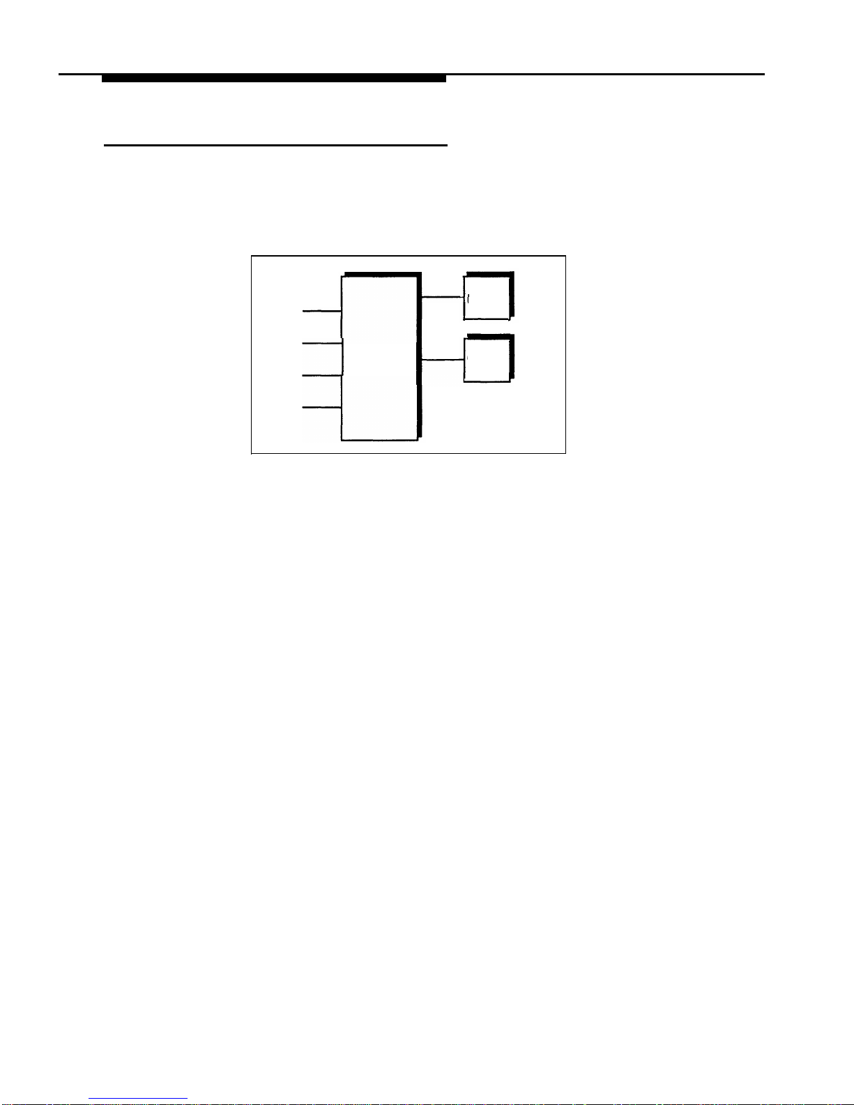
Multiple Answering Machines
If a single answering machine cannot handle all your calls, you can set up two
or more machines at different extensions (Figure 4-2) so that a call does not go
unanswered. If one answering machine is busy, a second call will be answered
by the second machine. A setup such as this might be used by a movie theater
to announce movie times to people calling for information.
Lines
Ext X
ANS
MACH
1
CONTROL
Ext Y
ANS
UNIT
MACH
2
Figure 4-2.
Multiple Answering Machines
To Use
Go to the machines to manually play back messages.
■
■
■
From any system extension, make an intercom call to an answering
machine extension. When the machine answers, dial its message
retrieval code.
From outside the system, call in on any line assigned to the machine.
When the machine answers, dial its message retrieval code. Note,
however, when calling in from outside, you can retrieve messages only
from the first machine that answers.
To Program
1.
For extensions X and Y, set Line Ringing for all lines to Immediate Ring.
2.
Use Line Assignment (#301) to assign all the lines to extensions X and Y that
you want the machines to cover.
3.
Make sure extensions X and Y are not assigned as Pickup Group Extensions
(#501), Calling Group Extensions (#502), Night Service Group
Extensions (#504), or Hunt Group Extensions (#505).
4.
Adjust both answering machines to answer on a different number of rings (so
they do not both try to pick up the same call). For example, set answering
machine 1 to 4 rings and answering machine 2 to 6 rings. (If you cannot
adjust the two answering machines to answer on a different number of
rings, assign some lines to Immediate Ring at extension X and other lines
to Immediate Ring at extension Y.)
4-6
Using Auxiliary Equipment
Page 60
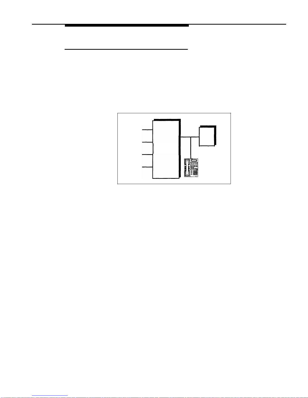
Personal Answering Machine
A personal answering machine is used to answer all the calls that ring at a
certain extension (Figure 4-3). It is useful for the following situations:
■
When you do not want to dedicate an extension to an answering machine
■
When the extension receives a lot of intercom calls
■
When outside calls come through a receptionist and are transferred to the
extension
■
When an extension has a private line
Lines
Ext X
ANS
MACH
CONTROL
UNIT
Figure 4-3.
Personal Answering Machine
To Use
■
Go to the machine to manually retrieve messages.
■ From any system extension, make an intercom call to the extension.
When the machine answers, dial the message retrieval code.
■ From outside the system, call in and have someone transfer you to the
extension. When the machine answers, dial the message retrieval code.
Or, call in when no one will answer before the answering machine does.
To Program
1.
Set Line Ringing for all lines assigned to extension X to the desired ring
(Immediate, Delayed, or No Ring).
2.
If the lines assigned to extension X are also assigned to other extensions,
adjust the answering machine to answer on the third or fourth ring so that it
does not answer calls before someone else can.
NOTE:
If you intercept a call from the answering machine, you will hear a click to notify
you that the answering machine has turned off.
Using Auxiliary Equipment
4-7
Page 61

Call Reporting Devices (SMDR)
SMDR (Station Message Detail Recording) is a call reporting feature that
provides records of call activity. Call reporting information provides you with the
ability to:
■
■
■
■
Detect any unauthorized calls
Bill clients or projects
Bill back by departments
Reduce telephone costs by identifying the need to change
telecommunications services (like adding a WATS line for calls to a
particular area code)
Call reporting information is recorded after each call is completed. The system
records information for each call that lasts at least 10 seconds. For outgoing
calls, the timing begins when you get dial tone. For incoming calls, the timing
begins when you answer the call. Timing stops when the call is disconnected.
The system sends the information through a 1200-baud serial interface to either
a serial printer or a call accounting device. The device connects directly to the
SMDR jack on the processor module.
Programming
Use the following programming procedures for call reporting:
■
■
■
■
SMDR Record Type (#608) to specify the type of calls that you want to
record for call reporting—either all calls or outgoing calls only.
SMDR Top of Page (#609) to notify the system that the printer has been
aligned to the top of a new page.
Forced Account Code Entry (#307) to identify extensions that are
required to enter an account code prior to making outside calls and
Forced Account Code List (#409) to create a list of valid account codes.
Display Language (#303) to specify the language to be used for display
messages. The call report header is printed in the same language as is
specified for extension 10.
4-8
Using Auxiliary Equipment
Page 62
Call Reports
A call report is a page of information that begins with a header. The header
includes field names that describe the information in each call record. The call
record is a line of information that includes the fields shown in Figure 4-4.
DATE
TIME
CALLED NUMBER
DUR.
LINE
STN.
ACCOUNT
C 11/17/93 11:11
12015558014
00:01:40
08
18
C 11/17/93 11:34
19085556036
00:04:28
02
32 1725
I 11/17/93 13:35
IN
00:02:12
01
10
Figure 4-4.
Sample Call Report
Each page includes 59 records. The report has the following fields:
■
■
■
■
■
■
■
■
Call Type. “C” indicates outgoing calls; “I” indicates incoming calls.
(SMDR Record Type (#608) defines whether or not incoming calls are
reported.)
Date. The date of the call is shown in mm/dd/yy format, where mm is the
month, dd is the day, and yy is the year. The system uses the date set
with System Date (#101).
Time. The time of the connection is shown in hh:mm format, where hh is
the hour and mm is the minute. The system uses the time set with
System Time (#103) and is shown in 24-hour (military) time.
Number. For an outgoing call, this is the dialed number (first 15 digits
only) or the speed dial code of a Marked System Speed Dial number
(preceded by an “F”). For an incoming call, “IN” appears in this field.
A “*” character prints as the last digit of a dialed number if the called
party hangs up before the system user, or a “?” prints if the number of
digits dialed exceeds the 15 digits that this field can hold.
Duration. The duration of the call is shown in hh:mm:ss format, where hh
is the hour, mm is the minutes, and ss is the seconds. This is the total
time of the call, including any time the call is on hold.
Line Number. This is the outside line (01–12) that was used to make or
receive the call.
Station (Extension). In general, this is the extension that answered or
placed the call. For redirected incoming calls, the last extension on the
call is shown on the report, as follows:
– For transferred incoming calls: the destination extension.
–
For transferred outgoing calls: the originator extension.
–
For pickup calls: the extension picking up the call.
–
For forwarded calls: the extension answering the forwarded call.
Account Code. This is the account code (up to 16 digits) assigned to
the call. This code is typically used for charging calls to a specific
project or department.
Using Auxiliary Equipment
4-9
Page 63

Considerations
■
■
■
■
■
■
The System Date (#101) and System Time (#103) must be set correctly
to ensure accurate call reports.
If a report cannot print because the printer is jammed or out of paper, the
system will store up to 45 records in its memory until they can be printed.
Additional calls will not be recorded.
In the event of a power failure, records of any calls in progress are lost.
Inside (intercom) calls are not recorded.
If you place a call on hold and the caller hangs up, the call is considered
complete and the record is sent to the call reporting device.
Conference calls appear as two outside calls. (This means two records
are generated on the report.)
Output Format
The following serial transmission protocol is used for SMDR records:
■
1200 baud
■
no parity
■
8 data bits
■
2 stop bits
The call reporting feature also supports XON/XOFF protocol, carriage returns,
and line feeds.
Serial Printers
Use a 355A adapter, which converts a modular jack interface to an RS-232
25-pin connector, to connect a serial printer to the processor module. If you
connect a printer, make sure the printer can receive SMDR data in the format
described above (refer to the printer’s instructions if you need help).
Call Accounting Devices
You can send call information to a call accounting device (such as AT&T’s Call
Accounting Terminal—Basic or Plus) if you want to further analyze call activity.
The device stores rate table information and processes the information it
receives into meaningful reports that can help you optimize your
communications system. For example, you can use it to determine the best
combination of local and long distance lines for your business.
The call accounting device connects directly to the SMDR jack on the processor
module and can also print out reports that include summaries by hour, line, and
extension. Refer to the manual provided with the call accounting device for
instructions on connecting it to your system.
4-10
Using Auxiliary Equipment
Page 64
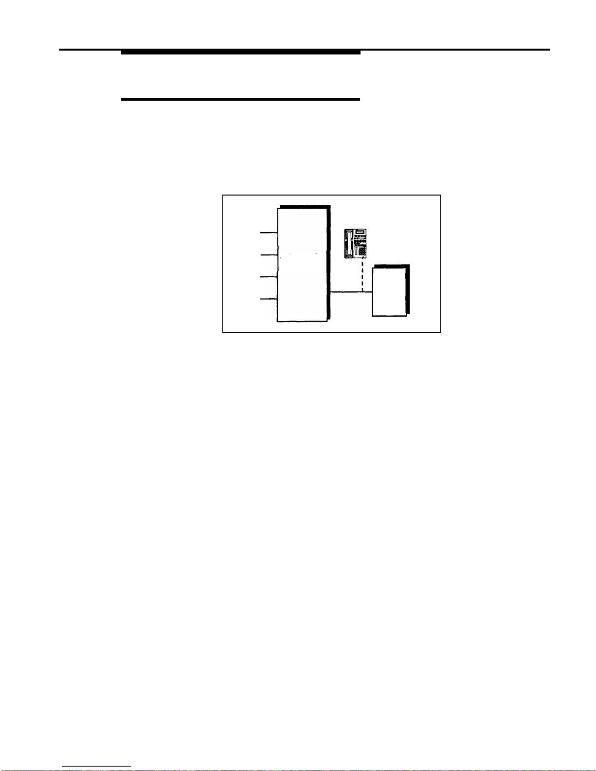
Credit Card Scanners
Many retail businesses and restaurants use credit card scanners to get instant
approval of credit card purchases. The system allows your credit card
scanners to share the lines in your system (as shown in Figure 4-5). You can
install the credit card scanner on an extension by itself, or combine it with a
system phone or a standard phone on the same extension (see “Combination
Extensions” in the PARTNER Plus Communications System Installation guide).
Lines
Telephone
(optional)
CONTROL
UNIT
Ext
Credit
X
Card
Scanner
Figure 4-5.
Credit Card Scanner
To Use
When you make a call on the credit card scanner, an outside line is
automatically selected. If you combine the credit card scanner with a system
phone or standard phone, you cannot use the phone while the credit card
scanner is operating. You can use only one of the devices at a time.
To Program
1.
Set Automatic Line Selection for extension X to select outside lines first.
2.
Use Line Assignment (#301) to assign the lines you want the scanner to use
to extension X.
3. Set Automatic Extension Privacy (#304) for extension X to Assigned.
4.
If the scanner has an auto answer feature, turn it off.
5.
For multiple scanners, repeat Steps 1–4 for each extension.
Using Auxiliary Equipment
4-11
Page 65

Fax Machines
This section suggests several ways you can set up fax machines to work with
your system. It includes instructions for programming and using a Fax
Management button on a system phone (in order to monitor the status of a fax
machine and transfer calls to it with a single touch), transferring calls to the fax
machine extension, and using an AT&T fax machine’s Notify feature.
Using Fax Machines
Fax Management Feature
On any system phone, you can program a button with lights to serve as a Fax
Management button. The lights next to this button tell you when the fax machine
is in use, available, or not answering (for example, when it is out of paper). You
can also use the button to transfer calls from your extension to the fax machine
with a single touch.
Programming for Fax Management
To program a Fax Management button, first assign the fax machine extension
using Fax Machine Extensions (#601). (See Chapter 5 for details.) Then
program the fax machine extension number on an Auto Dial button. For more
information, see “Auto Dialing” in Chapter 5.
Using the Fax Management Button
The lights next to the Fax Management button show what is happening at the fax
machine—see Table 4-1.
Table 4-1. Fax Management Button Light Patterns
Light Pattern
Indicates...
Red broken
Fax trouble. The fax machine is not answering.
flutter
If broken flutter occurs because the fax machine
is out of paper, refill the paper. The light clears
the next time the machine transmits or receives
a call. If the machine takes longer than four
rings to answer, the light shows fax trouble;
when the machine does answer, the light
changes to fax busy (red steady).
Red steady
Fax busy. The fax machine is busy transmitting
or receiving a call.
Green flash
Fax calling. The green flash indicates that the
fax machine extension is calling you. An AT&T
fax machine with the “Notify” feature can call
you automatically after it receives a
transmission. See “Using the Fax Machine’s
Notify Feature” on the next page.
Green flutter
Fax transfer return. A call you transferred to
the fax machine was not answered and is
returning to you.
4-12
Using Auxiliary Equipment
Page 66

Transferring a Call to the Fax Machine
There are two situations in which you would want to transfer a call to your fax
machine:
■ You answer an outside call and hear a fax machine signaling. (A fax
signal is a single beep sequence— beep . . . . beep . . . . beep). If you
hear this, you should transfer the call immediately to the fax machine
extension.
■
You are on a call with a person who wants to send you a fax using the fax
machine that is connected to his or her phone. You can receive the fax
by transferring the call to your fax extension. Tell the other party to wait
until he or she hears the fax signal before pressing the Start button on
their fax machine.
In addition, if you have a PARTNER MAIL system and a fax call comes in on a
line covered by the PARTNER MAIL system, its Automated Attendant Service
can be programmed to automatically transfer the call to a fax extension or (if you
have multiple fax machines) to the extension Hunt Group for the fax machines.
There are four ways to transfer the call to the fax extension:
■
■
■
■
If you have a Fax Management button, simply press the button. When the
fax machine answers, hang up.
If you do not have a Fax Management button, press
Transfer plus the fax
machine’s extension number. When the fax machine answers, hang up.
On a standard phone, rapidly press and release the switchhook to place
the call on hold, then dial the fax extension number and hang up.
If you have multiple fax machines in an extension Hunt Group, press
Transfer
,
then
Intercom
7 7
plus the fax extension Hunt Group number.
When a fax machine answers, hang up.
Using the Fax Machine’s Notify Feature
Some AT&T fax machines (for example, models 5300, 5350, 9025 Plus, and
9035 Plus) have a feature called Notify. After such a machine receives a fax
call, it automatically dials a number and plays a recorded message, such as,
“You have just received a fax.” If you need to know exactly when a fax comes
in, or if your fax machine is located in an isolated part of your building, you can
use Notify in any of the following ways:
■
Program the fax machine to make a ringing or voice-signaled intercom
call to an individual extension or to a group. (Program the fax machine to
dial
✴
plus the extension number for a voice-signaled call;
7
and a
group number (1–4) for a call to a Calling Group;
7 7
and a group
number (1–6) for a call to a Hunt Group.)
■
Program the fax machine to turn on the message light at someone’s
extension by dialing
# 0 9
plus the extension number.
■
Program the fax machine to dial
7 0
to make its recorded
announcement over your loudspeaker paging system.
Using Auxiliary Equipment
4-13
Page 67

For all of these examples, program the fax machine extension’s Automatic Line
Selection to select intercom first, followed by whatever outside lines you want to
assign to it. (If you set the fax extension to select intercom first and the machine
has an auto dial feature, program a 9 and a few pauses before each Auto Dial
number. When manually making a call, dial
9 to get an outside line. For
instructions on how to set the Automatic Line Selection, see Chapter 5.)
Setting Up Fax Machines
There are many ways to set up fax machines. The following configurations are
basic and easy to use:
■
■
■
Single fax machine. Good for light or moderate fax traffic. This basic
setup uses a published fax number.
Fax machine line saver. Good for light fax traffic, with no need for a
published fax number.
Send and receive fax machines. Good for high-volume fax traffic. One
machine sends, the other receives.
You can install both a telephone and a fax machine on the same extension—see
“Combination Extensions” in the PARTNER Plus Communications System
Installation guide. This lets you receive both voice and fax calls on the same
line (but not at the same time). If you pick up the phone and hear a fax signal,
push the Start button on your fax machine and then hang up.
If you are using the PARTNER MAIL system’s Automated Attendant Service, you
can program PARTNER MAIL to transfer fax calls to the fax extension or a group
of fax extensions automatically. Use Fax Machine Extensions (#601) to identify
fax extensions. If you have multiple fax machines, put all of the fax extensions
into a single Hunt Group (any of groups 1–6) using Hunt Group Extensions
(#505).
Restricting Dialing from a Fax Machine
You can use dialing restrictions to restrict calling activity on a fax machine. For
example, you can use Outgoing Call Restriction (#401) to restrict the fax
restrictions, see Chapter 2.
machine to local calls only. For a more detailed discussion of dialing
4-14
Using Auxiliary Equipment
Page 68
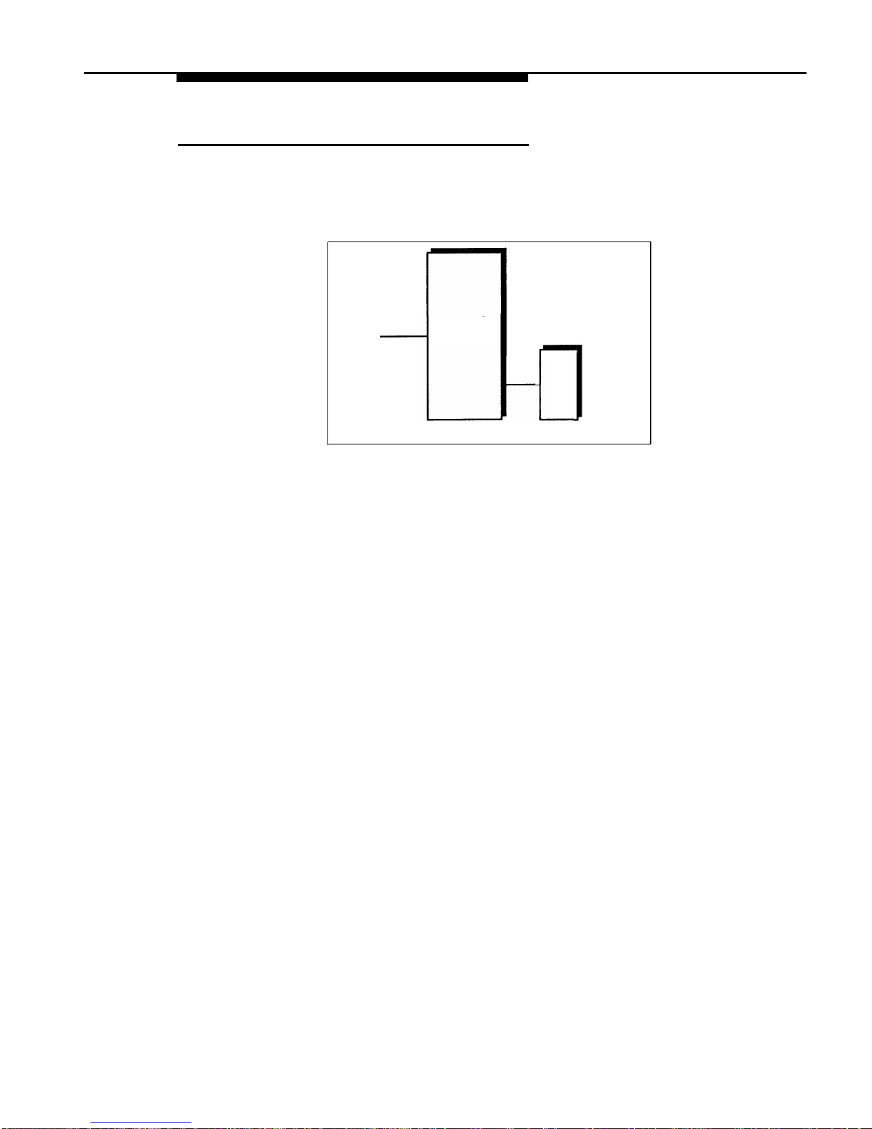
Single Fax Machine
The single fax machine setup (shown in Figure 4-6) is good for moderate traffic.
The fax machine has its own line (Line A), the number of which is published as
the fax number. (The fax line can be used by other phones when all other lines
are busy.) The fax machine is connected to its own extension (extension X).
Fax
Line A
CONTROL
UNIT
Ext
X
FAX
Figure 4-6.
Single Fax Machine
To Use
The fax machine automatically answers all calls that come in on the fax line. If a
call comes in on another line, you can transfer the call to the fax extension (see
“Transferring a Call to the Fax Machine”). If you have programmed a Fax
Management button, you can transfer a call to the fax machine with a single
touch, as well as monitor the status of the fax machine (see “Fax Management
Feature” earlier in this chapter).
When you send a fax, the system automatically selects the fax line.
To Program
1.
2.
3.
4.
5.
6.
Set Automatic Line Selection for extension X to select line A only. Set
Automatic Line Selection to select line A last on all other extensions or
remove line A if all other extensions should not use it to make outgoing
calls.
Set Line Ringing for line A on extension X to Immediate Ring. On all other
extensions, set line A to Delayed Ring or No Ring.
Use Line Assignment (#301) to assign only line A to extension X.
Set Automatic Extension Privacy (#304) for extension X to Assigned.
Make sure extension X is not assigned as a Pickup Group Extension (#501),
Calling Group Extension (#502), Night Service Group Extension
(#504),
or
Hunt Group Extension (#505).
To monitor the fax machine, use Fax Machine Extensions (#601) to identify
extension X as a fax extension and program a Fax Management button by
programming the fax machine extension number on an Auto Dial button.
Using Auxiliary Equipment
4-15
Page 69
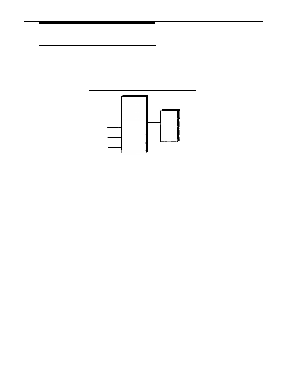
Fax Line Saver
If you do not use your fax machine enough to justify paying for its own outside
line, you can put the machine on its own extension. With this setup, you must
transfer calls to it manually. If you have programmed a Fax Management
button, you can transfer a call to the fax machine with a single touch, as well as
monitor the status of the fax machine (see “Fax Management Feature” earlier in
this chapter). Figure 4-7 shows the setup.
Lines
Ext X
A
CONTROL
UNIT
FAX
B
C
Figure 4-7.
Fax Line Saver Setup
To Use
When a person answers a call and hears a fax machine signaling on the other
end, the person can transfer the call to extension X—the fax machine extension.
To send a fax transmission, simply lift the handset on the fax machine—an
outside line will be automatically selected.
To Program
1.
2.
3.
4.
5.
6.
Set Automatic Line Selection for extension X to Line A, B, C, . . . .
Set Line Ringing for all lines on extension X to No Ring.
Use Line Assignment (#301) to assign all lines to extension X.
Set Automatic Extension Privacy (#304) for extension X to Assigned.
Make sure extension X is not assigned as a Pickup Group Extension (#501),
Calling Group Extension (#502), Night Service Group Extension
(#504), or Hunt Group Extension (#505).
To monitor the fax machine, use Fax Machine Extensions (#601) to identify
extension X as a fax extension and program a Fax Management button by
programming the fax machine extension number on an Auto Dial button.
4-16 Using Auxiliary Equipment
Page 70
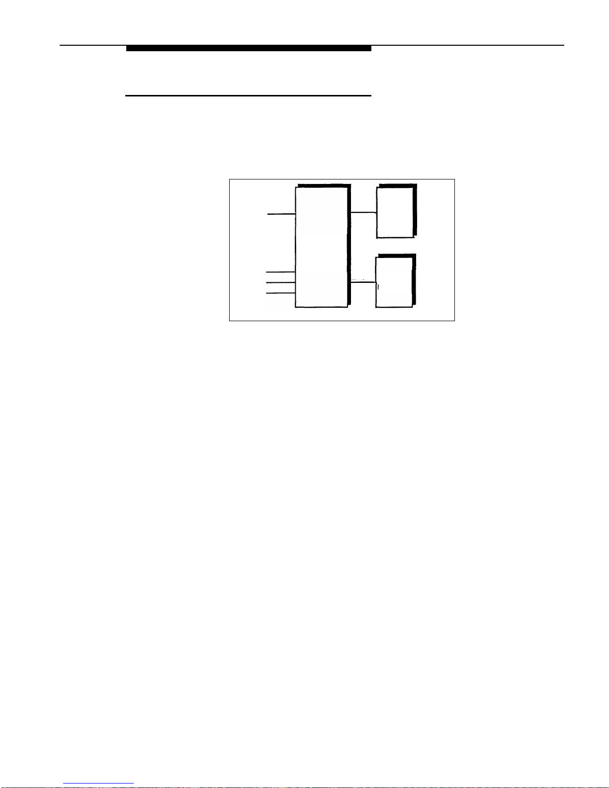
Send and Receive Fax Machines
If your business has high-volume fax traffic, you can set up two fax machines,
one that only sends and the other that only receives. For example, in Figure 4-8,
fax 1 is the send machine, fax 2 is the receive machine. Line A is the fax line,
the number of which is published as the fax number. If fax 2 doesn’t answer line
A, fax 1 will.
Fax
Line A
Ext X
FAX 1
Send
Lines
CONTROL
UNIT
Ext Y
FAX 2
Receive
Figure 4-8.
Send and Receive Fax Machines
To Use
When you send a fax, an outside line will be automatically selected. Incoming
fax calls on the fax line are answered automatically by fax 2. If a fax comes in
on a line other than line A, you can transfer the call to fax 2 (see “Transferring a
Call to the Fax Machine” earlier in this chapter). If you have programmed a Fax
Management button, you can transfer a call to the fax machine with a single
touch, as well as monitor the status of the fax machine (see “Fax Management
Feature” earlier in this chapter). If fax 1 is set for Delayed Ring on line A, fax 1
can pick up fax transmissions when fax 2 does not answer.
To Program Fax 1 (Send—Ext. X)
1.
Set Automatic Line Selection for extension X to select outside lines first (line
A selected last).
2.
Set Line Ringing for line A at extension X to Delayed Ring; set all other lines
to No Ring.
3.
Use Line Assignment (#301) to assign one or more lines to extension X
(including line A).
4.
Set Automatic Extension Privacy (#304) for extension X to Assigned.
5.
Make sure extension X is not assigned as a Pickup Group Extension (#501),
Calling Group Extension (#502), Night Service Group Extension
(#504), or Hunt Group Extension (#505).
6.
To monitor the fax machine at extension X, use Fax Machine Extensions
(#601) to identify extension X as a fax extension and program a Fax
Management button by programming the fax machine extension number
on an Auto Dial button.
Using Auxiliary Equipment
4-17
Page 71

To Program Fax 2 (Receive—Ext. Y)
1.
2.
3.
4.
5.
6.
If the fax machine has the Notify feature, set it to select intercom first. If the
fax machine does not have the Notify feature and you want it to be able to
dial out when fax 1 is unavailable, set Automatic Line Selection for
extension Y to select outside lines first (line A selected last).
Set Line Ringing for line A at extension X to Immediate Ring; set all other lines
at extension Y to No Ring. (For all other extensions, set line A to No Ring or
Delayed Ring.)
Use Line Assignment (#301) to assign only line A to extension Y.
Set Automatic Extension Privacy (#304) for extension Y to Assigned.
Make sure extension Y is not assigned as a Pickup Group Extension (#501),
Calling Group Extension (#502), Night Service Group Extension (#504),
or
Hunt Group Extension (#505).
To monitor the fax machine at extension Y, use Fax Machine Extensions
(#601) to identify extension Y as a fax extension and program a Fax
Management button by programming the fax machine extension number
on an Auto Dial button.
4-18
Using Auxiliary Equipment
Page 72
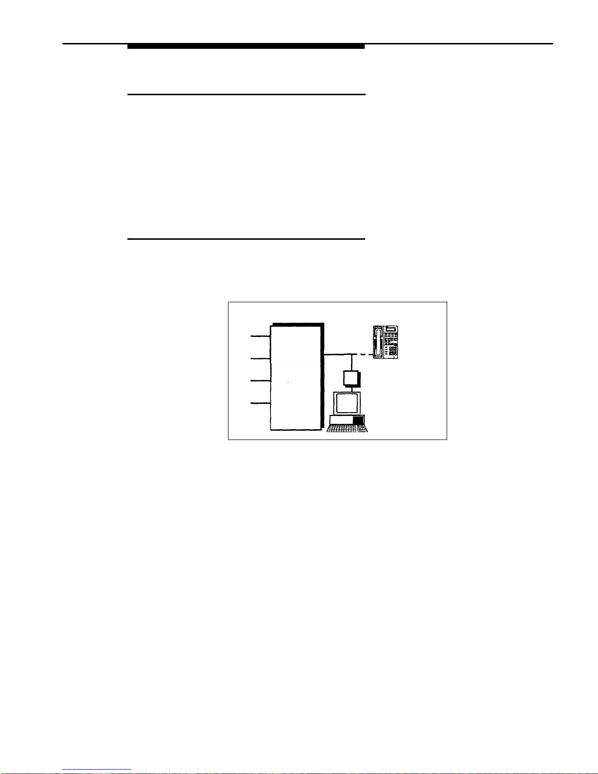
Modems
There are several ways to use modems with your system, as described below.
NOTE:
Modems can connect directly to an extension jack without an adapter.
However, if you connect a high-speed modem through the control unit, you may
experience some degradation of efficiency and throughput, depending on the
quality of the central office lines connected to the system. To solve the problem,
either connect modems directly to the network interface jacks, or contact your
local telephone company for information about upgrading line quality.
Stand-Alone Modem for Placing Calls Only
A modem and a terminal allow you to dial out and connect to computer bulletin
boards and other data services. This setup, which lets you dial out but not
receive calls, is shown in Figure 4-9. Note that the telephone is optional and
can be used if you want the terminal to share an extension with a phone.
Lines
Telephone
(optional)
Ext
CONTROL
X
UNIT
Modem
PC or
Terminal
Figure 4-9.
Stand-Alone Modem for Placing Calls Only
To Use
Follow the modem manufacturer’s instructions.
To Program
1.
2.
3.
4.
5.
6.
If the modem will only dial outside the system, set Automatic Line Selection
for extension X to select outside lines first. If you also use the modem for
calls within the system, set Automatic Line Selection to select intercom
first, and include a 9 in the modem’s dialing sequence for outside calls.
Set Line Ringing for all lines assigned to extension X to No Ring.
Use Line Assignment (#301) to assign one or more lines to extension X.
Set Automatic Extension Privacy (#304) for extension X to Assigned.
Make sure extension Y is not assigned as a Pickup Group Extension (#501),
Calling Group Extension (#502), Night Service Group Extension (#504),
or Hunt Group Extension (#505).
Set the auto answer feature of the modem to Off.
Using Auxiliary Equipment
4-19
Page 73
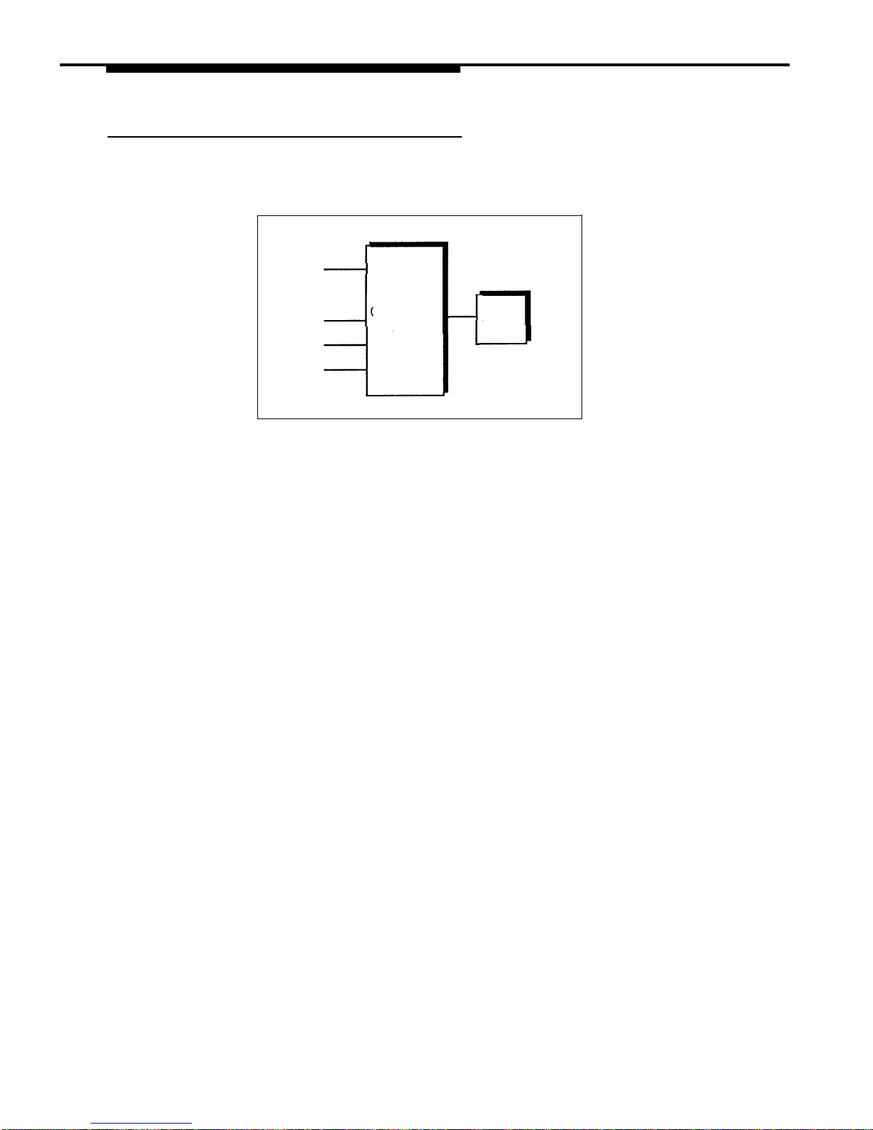
Send and Receive Modem
If you need to place and receive calls with the modem, use the setup shown in
Figure 4-10. This setup makes line A the primary modem line, but keeps the line
available for users at other extensions when all other lines are busy.
Modem
Line A
Ext
CONTROL
X
UNIT
Lines
MODEM
Figure 4-10.
Send and Receive Modem
To Use
Calls on the modem line (line A) ring only at extension X. Likewise, line A is the
last line selected by other extensions in the system, so the modem line is
unavailable for the modem only when all other lines in the system are being
used.
To Program
1.
Set Automatic Line Selection for all other extensions so that line A is the last
line in the select sequence. That way, the modem line is used for outgoing
voice calls only when all other lines are busy.
2.
Set Line Ringing for all lines assigned to extension X to No Ring.
3.
Use Line Assignment (#301) to assign one or more lines to extension X.
4.
Set Automatic Extension Privacy (#304) for extension X to Assigned.
4-20
Using Auxiliary Equipment
Page 74
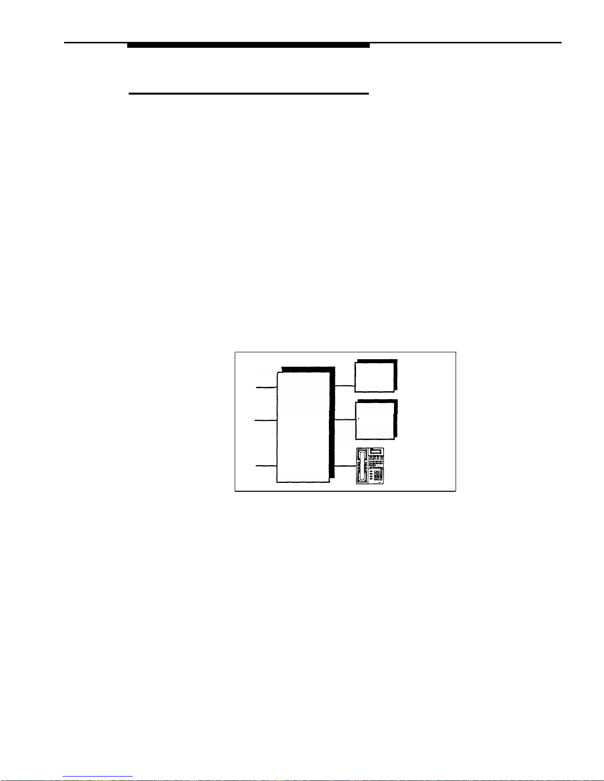
Night Service with Auxiliary Equipment
You can set up modems, fax machines, and answering machines to receive
calls automatically after hours. When Night Service is on, calls ring immediately
at the appropriate extensions, so that no human intervention is required to
transfer calls to the fax, modem, or answering machine. When Night Service is
off, you can use the auxiliary equipment lines for normal business purposes, so
that lines are dedicated to auxiliary equipment only after hours.
By putting auxiliary equipment in the Night Service Group as described in this
section, auxiliary equipment can start ringing and answering calls whenever you
turn Night Service on. In other words, the Night Service button at extension 10
acts like a switch, turning auxiliary equipment on and off, as well as putting the
system into Night Service.
NOTE:
If you have a voice messaging system, turning Night Service on also activates
Night Service operation of the voice messaging system.
Figure 4-11 shows a system with a fax machine and a modem connected to
separate extensions. Line A is published as the fax line, and line B is published
as the modem line.
Lines
A
Ext
X
FAX
B
Ext
Y
CONTROL
UNIT
MODEM
C
Ext
Z
Figure 4-11.
Night Service with Fax Machine and Modem
To Use
During the day, lines A and B do not ring at extensions X and Y. When you turn
Night Service on, calls on line A ring immediately at the fax (extension X). Since
that line is not assigned to any other extension in the Night Service Group, only
extension X receives fax transmissions. Likewise, with Night Service on, calls on
line B ring immediately at the modem (extension Y). All lines ring at the system
phone at extension Z.
Using Auxiliary Equipment
4-21
Page 75

NOTE:
If answering machines are connected to Night Service extensions, you can join
a call that was already answered by an answering machine from any system
phone. If you have an AT&T answering machine with the Call Intercept feature,
the answering machine drops off the call when you join it.
To Program
1.
2.
3.
4.
5.
Set Line Ringing for line A at extension X and for line B at extension Y to No
Ring.
Use Line Assignment (#301) to assign line A to extension X (for the fax
machine to cover), line B to extension Y (for the modem to cover), and all
lines to extension Z.
Make sure extensions X and Y are not assigned as Pickup Group Extensions
(#501), Calling Group Extensions (#502), or Hunt Group Extensions
(#505).
Assign a Night Service Button (#503) at extension 10.
Assign extensions X and Y to the Night Service Group (#504).
4-22
Using Auxiliary Equipment
Page 76
PARTNER Attendant
The PARTNER Attendant answers calls and directs them to a specified
extension or to a Hunt Group (based on the digits a caller dials after listening to
a list of choices in a recorded greeting). For example, the PARTNER Attendant
could answer calls and tell callers to press 1 for Sales, 2 for Parts, 3 for Service,
and so on. The PARTNER Attendant can be set up for immediate call handling
or delayed call handling.
Backup for Receptionist
A common use of PARTNER Attendant is as a backup for the receptionist. If the
receptionist cannot pick up a call within a specified number of rings, PARTNER
Attendant handles it. This prevents calls from going unanswered. Figure 4-12
shows how the PARTNER Attendant would be connected to your system.
PARTNER
Attendant
Lines
Ext.
CONTROL
UNIT
X
Ext.
10
Receptionist's
Desk
Figure 4-12. Backup for Receptionist
To Use
Follow the instructions packaged with the PARTNER Attendant. Make sure that
the unit is in backup call answering mode.
When callers call the main number for your company, the receptionist normally
picks up the call. If the receptionist is busy, the PARTNER Attendant answers
and plays a recorded message, such as: “Please hold for the receptionist or
dial an extension number now.”
To Program
1.
2.
Set Line Ringing for all lines assigned to the PARTNER Attendant to Delayed
Ring.
Set the PARTNER Attendant to pick up within a specific number of rings, so if
the receptionist does not pick up a call, the PARTNER Attendant will.
Using Auxiliary Equipment
4-23
Page 77

Voice Messaging Systems
Two voice messaging systems are compatible with your system. You can install
one or the other, depending on your business needs:
■
The PARTNER MAIL VS Voice Messaging System, which physically
resembles a 206 module, resides in the control unit and provides voice
messaging capabilities for up to 10 subscribers. An optional Mailbox
Expansion Card can extend service for up to 20 subscribers.
■ The PARTNER MAIL Voice Messaging System is an auxiliary device
that connects to the system through extension jacks. It is available in a
2-port or 4-port configuration, providing service for up to 20 or 40
subscribers, respectively.
Both voice messaging systems offer your business complete call processing
features. Specifically, they can:
■
■
■
■
Insure that incoming calls are answered and directed to destination
extensions correctly and efficiently, using immediate or delayed call
handling. (Immediate call handling sends calls directly to the voice
messaging system, while delayed call handling allows the receptionist to
answer calls first.)
Answer and route calls during the day and after normal business hours.
Alleviate the problem of inaccurate or incomplete messages by allowing
callers to leave detailed, confidential messages for subscribers.
Allows subscribers to assign a password to their mailbox, change their
personal greeting, and retrieve messages.
The PARTNER MAIL system also offers advanced voice mail features, such as
outcalling, group lists, broadcast messages, and fax management. You can
refer to the documentation provided with your voice messaging system for
complete details.
Delayed Call Handling
Figure 4-13 shows a PARTNER MAIL VS system that provides delayed call
handling. This setup allows the receptionist at extension 10 to provide
personalized service by answering calls during the day. The PARTNER
MAIL VS system (connected to extensions Z1 and Z2) is used to handle calls
when the receptionist is busy or not available, so calls do not go unanswered.
The PARTNER MAIL VS system also answers calls received after business
hours and prompts callers to leave a message in the receptionist’s mailbox.
This example also includes two user extensions (X and Y), which are not
automatically covered by the PARTNER MAIL VS system. This allows the
receptionist to give the caller more personalized service; if the receptionist
transfers a call to extension X or Y and that extension does not answer, the call
returns to the receptionist. The receptionist can then take a message or send
the call to the extension’s mailbox if the caller prefers.
4-24
Using Auxiliary Equipment
Page 78
PARTNER MAIL VS
Lines
System
Ext. Z1
Ext. Z2
CONTROL
UNIT
(not automatically
Ext. X
covered by the
PARTNER MAIL VS
Ext. Y
System)
Ext. 10
Receptionist’s Desk
Figure 4-13. Delayed Call Handling
To Use
Follow the instructions packaged with the PARTNER MAIL VS system to install it.
During the day, the PARTNER MAIL VS system uses delayed call handling; the
receptionist picks up all calls at extension 10. If the receptionist cannot answer
within four rings, the system routes the call to the PARTNER MAIL VS system
where the day menu plays to the caller. At night (when Night Service is
activated at extension 10), outside calls are answered directly by the PARTNER
MAIL VS system. Any user who is still in the office can pick up calls before the
PARTNER MAIL VS system answers.
To Program
The following list summarizes the PARTNER Plus system programming
procedures you use to implement the previous example:
1.
Use Group Call Distribution (#206) to assign outside lines to Hunt Group 7
(the VMS hunt group) to provide Automated Attendant Service on these
lines.
2.
Use Transfer Return Extension (#306) for extensions Z1 and Z2 to ensure
that calls transferred by the PARTNER MAIL VS system return to extension
10 if they are not answered.
3.
Use Hunt Group Extensions (#505) to assign extensions Z1 and Z2 to Hunt
Group 7 (the VMS hunt group).
4.
Set the VMS Hunt Delay (#506) to Delayed.
5.
Set the VMS Hunt Schedule (#507) to Always.
6.
Make sure that a Night Service Button (#503) is assigned at extension
10—the receptionist’s extension. When Night Service is on, callers hear
the night menu when no one is available to answer their calls.
7.
Program a Voice Mailbox Transfer button at extension 10 to enable the
receptionist to transfer calls directly to extension X’s and Y’s mailboxes
without first ringing their phones. (This is useful when the receptionist
knows that the users at extensions X and Y are away from their desk.)
8.
Program an Auto Dial button for the VMS hunt group
(
Intercom
7 7 7 )
at
extensions X and Y to allow the subscribers to call in for their messages
with one touch.
Using Auxiliary Equipment
4-25
Page 79

Feature Reference
5
Contents
Overview
5-1
AA Extensions (#607)
5-2
Abbreviated Ringing (#305)
5-3
Account Code Entry (F12)
5-4
Allowed List Assignments (#408)
5-7
Allowed Phone Number Lists (#407)
5-8
Answering Calls
5-10
Auto Dialing
5-12
Automatic Extension Privacy (#304)
5-14
Automatic Line Selection
5-15
Automatic VMS Cover (#310)
5-17
Background Music (F19)
5-18
Call Forwarding/Call Follow-Me (F11)
5-20
Call Pickup (I6XX)
5-22
Calling Group Extensions (#502)
5-23
Conference Calls
5-24
Conference Drop (F06)
5-26
Copy Settings (#399)
5-27
Dial Mode (#201)
5-28
Direct Line Pickup—Active Line (I68LL)
5-29
Direct Line Pickup—Idle Line (I8LL)
5-31
Disallowed List Assignments (#405)
5-32
Disallowed Phone Number Lists (#404)
5-33
Display
5-35
Display Language (#303)
5-37
5-i
Page 80

Contents
Distinctive Ring (#308)
Do Not Disturb (F01)
Doorphone Alert Extensions (#606)
Doorphone Extension (#604 and #605)
Emergency Phone Number List (#406)
Emergency Telephone (#311)
Exclusive Hold (F02)
Extension Name Display
Fax Machine Extensions (#601)
Forced Account Code Entry (#307)
Forced Account Code List (#409)
Group Call Distribution (#206)
Group Calling—Ring/Page (I7G/I*7G)
Group Hunting—Ring/Voice Signal (I77G/I*77G)
Group Pickup (I66G)
Hold
Hold Disconnect Time (#203)
Hotline (#603)
Hunt Group Extensions (#505)
Intercom Dial Tone (#309)
Joining Calls
Last Number Redial (F05)
Line Access Restriction (#302)
Line Assignment (#301)
Line Ringing
Loudspeaker Paging (I70)
Making Calls
Message Light Off (F10)
Message Light On (F09)
Music On Hold (#602)
Night Service Button (#503)
Night Service Group Extensions (#504)
Number of Lines (#104)
Outgoing Call Restriction (#401)
5-38
5-39
5-40
5-41
5-42
5-44
5-46
5-47
5-49
5-50
5-52
5-54
5-56
5-58
5-61
5-63
5-65
5-66
5-68
5-70
5-71
5-73
5-74
5-76
5-78
5-80
5-82
5-86
5-88
5-90
5-92
5-94
5-95
5-96
5-ii
Page 81

Contents
Outgoing Call Restriction Button (#114)
Outside Conference Denial (#109)
Personal Speed Dial Numbers
Pickup Group Extensions (#501)
Privacy (F07)
Recall (F03)
Recall Timer Duration (#107)
Rotary Dialing Timeout (#108)
Save Number Redial (F04)
SMDR Record Type (#608)
SMDR Top Of Page (#609)
Special Dialing Functions
System Date (#101)
System Day (#102)
System Password (#403)
System Reset—Programming Saved (#728)
System Speed Dial Numbers
System Time (#103)
Toll Call Prefix (#402)
Touch-Tone Enable (F08)
Transferring Calls
Transfer Return Extension (#306)
Transfer Return Rings (#105)
VMS Cover (F15)
VMS Hunt Delay (#506)
VMS Hunt Schedule (#507)
Voice Interrupt On Busy (#312)
Voice Interrupt On Busy Talk-Back (F18)
Voice Mailbox Transfer (F14)
Wake Up Service Button (#115)
5-98
5-100
5-101
5-103
5-104
5-105
5-107
5-108
5-109
5-110
5-111
5-112
5-114
5-115
5-116
5-117
5-118
5-121
5-122
5-123
5-124
5-127
5-128
5-129
5-131
5-132
5-133
5-135
5-136
5-137
5-iii
Page 82

Feature Reference
■
5
Overview
This chapter provides reference information for programming and using system
features. Features are listed in alphabetical order. System Programming
procedures include the procedure code (# and three-digit number) in the
heading; dial-code features include the feature code (F for
Feature or I for
Intercom , plus a two-digit code). Some feature codes also include a variable:
XX for a two-digit extension number from 10–33, LL for a two-digit line number
from 01–12, or G for a single-digit group number. Headings with no codes are
general call-handling topics and Telephone Programming procedures.
Each feature includes the following information, if applicable:
■
■
■
Description
■
Examples
Related Features
■
Programming
Considerations
■
Using
Valid Entries (
✔
= factory setting)
This chapter gives step-by-step instructions, using the following conventions:
■
Programming instructions tell you to use the Next Data button to change
values for specific settings. You can, however, enter a value using the
keypad if you prefer. Similarly, there are different ways to exit
programming mode as described in Chapter 2—use the method with
which you are most comfortable.
■
For Telephone Programming, this chapter provides only the instructions
for Centralized Telephone Programming. To program from individual
extensions, users should refer to their Quick Reference cards.
All of the instructions in this chapter assume that system phones select outside
lines first and standard phones select intercom first (as determined by each
extension’s setting for Automatic Line Selection).
See Chapter 2 for a review of the methods and buttons you can use while in
programming mode.
Overview
5-1
Page 83

AA Extensions (#607)
Description
This System Programming procedure identifies extensions where PARTNER
Attendants are connected to the system. Doing so lets the system notify users
with display phones when they are receiving a call that has been transferred
from the PARTNER Attendant. (This procedure applies only to PARTNER
Attendants—do not use it with the Automated Attendant Service of a voice
messaging system.)
Related Features
■
For each PARTNER Attendant extension, use Transfer Return Extension
(#306) to identify the extension to which a call should be routed if the
destination extension does not answer.
■
Set Automatic Extension Privacy (#304) to Not Assigned for the PARTNER
Attendant extension if you want to be able to intercept calls routed to the
device.
Considerations
■
■
Chapter 4 provides information on using PARTNER Attendants with the
system.
On system display phones, “AA” displays when a call is being transferred
from a PARTNER Attendant. “Transfer from AA” displays when a call
transferred by a PARTNER Attendant was not answered and is being
returned to your extension.
Valid Entries
1 =
Assigned
2 = Not Assigned ✔
Programming
To identify an extension where a PARTNER Attendant is installed:
1.
2.
3.
4.
5.
Press
Feature
0 0
System Program
System Program
# 6 0 7 .
Enter the extension number to which the PARTNER Attendant is connected.
For example, to select extension 27, press
2 7 .
To assign or unassign the extension, press Next Data until the appropriate
value displays.
To assign or unassign a second PARTNER Attendant extension, press
Next Item or Prev Item until the extension number shows on the display.
Then repeat Step 3.
Select another procedure or exit programming mode.
5-2
AA Extensions (#607)
Page 84

Abbreviated Ringing (#305)
Description
This System Programming procedure turns Abbreviated Ringing on or off at a
specific extension. When a user is on a call and Abbreviated Ringing is on, any
incoming call rings only once. The green light next to the line button flashes
until the call is answered or the caller hangs up (or for a transferred call, until it
returns to the transfer return extension). This feature prevents incoming calls
from distracting users when they are busy on another call. To allow calls to ring
repeatedly, set Abbreviated Ringing to Not Active.
Considerations
■
■
■
■
■
Receptionists, and others who handle many calls quickly, often leave
Abbreviated Ringing off, so they have an audible reminder of incoming calls.
Abbreviated Ringing works for both outside calls and intercom calls.
The volume of an abbreviated ring is lower than a normal ring.
Calls to a busy extension ring at a lower volume than normal even if
Abbreviated Ring is set to Not Active.
This feature applies only to system phones.
Valid Entries
1 =
Active (incoming calls ring once) ✔
2 =
Not Active (incoming calls ring repeatedly)
Programming
To change the Abbreviated Ringing setting for an extension:
1.
Press
Feature
0 0
System Program
System Program
# 3 0 5 .
The
display reads:
Abbrev. Ring
Extension:
2.
Enter the number of the extension to be programmed. For example, to
program extension 12, press
1 2 .
3.
To set Abbreviated Ringing, press
Next Data ) until the appropriate value
displays.
4.
To set Abbreviated Ringing for another extension, press
Next Item or Prev Item
until the extension number shows on the display. Then repeat Step 3.
5. Select another procedure or exit programming mode.
Abbreviated Ringing (#305)
5-3
Page 85

Account Code Entry (F12)
Description
Related Features
This feature lets a user with a system phone enter an account code (up to 16
digits) for an outside call (incoming or outgoing). An account code is typically
used to identify a department, project, or client for charge-back or tracking
purposes.
■
■
■
You can use Forced Account Code Entry (#307) to identify extensions that
are required enter an account code prior to dialing any outside number
(including those on the Emergency Phone Number List). A forced account
code must be entered at the beginning of a call; however, a different
account code can be entered any time during the call. (Use Forced
Account Code Entry only for extensions with system phones.)
You can use Forced Account Code List (#409) to create a list of valid
account codes, which should be distributed to the appropriate users. If a
Forced Account Code List exists, the system checks the list whenever a
user enters a forced account code. If a forced account code is valid, the
system provides the user access to an outside line. If a forced account
code is invalid, the system denies the user access to an outside line—to dial
out, the user must repeat the procedure for entering a forced account code.
For faster entry of frequently-used account codes, you can program an
account code on an Auto Dial button or as a System or Personal Speed Dial
number (but not as a Marked System Speed Dial number). See Auto
Dialing, System Speed Dial Numbers, and Personal Speed Dial
Numbers for programming instructions.
Considerations
■
■
■
■
When an account code is entered during a call, the caller on the other end
does not hear the touch-tone digits dialed.
If SMDR is used, the account code assigned to incoming or outgoing calls
prints on call reports. (See “Call Reporting Devices (SMDR)” in Chapter 4
for more information on call reporting.)
If an account code is entered for an outgoing call and the call is transferred
to another extension, the call report shows the originating extension as the
owner of the call. Conversely, if an account code is entered for an incoming
call and the call is transferred to another extension, the call report shows the
destination extension as the owner of the call.
Account codes can be changed during a call. However, only the person
who entered the original account code can enter a different account code.
SMDR prints changed account codes as follows:
–
For optional or forced account code entry without a Forced Account
Code List, the call report prints the last account code entered.
–
For forced account code entry with a Forced Account Code List, the
call report prints the last valid account code entered. If the changed
account code is not valid, the report prints the original account code.
5-4
Account Code Entry (F12)
Page 86

■
■
■
■
If a Forced Account Code List exists, you can check to see if an account
code is valid when entering or changing an account code by pressing
Feature
1 2
after entering the account code. If the account code is not
valid, you will hear a denial tone.
The AT&T Call Accounting Terminal uses less than 16 digits for an account
code. Refer to the device’s documentation to determine the maximum
digits supported.
You can program the Account Code Entry feature code on a button on a
system phone. It is recommended that you use a button with lights. (This
button can be used for optional Account Code Entry or Forced Account
Code Entry.)
This feature can be used only from a system phone.
Programming
To program an Account Code Entry button:
1.
Press
Feature
0 0
System Program
System Program
Central Tel Program
.
2.
Enter the number of the extension to be programmed with this feature.
3.
Press a programmable button, preferably one with lights.
4.
Press
Feature
1 2 .
5.
Program another button for this extension or exit programming mode.
Using
To enter or change an optional account code:
1.
2.
3.
4.
5.
6.
From a system phone, if a password is programmed for the system, you must
enter it before lifting the handset. (See System Password (#403) for more
information.)
After lifting the handset (or while already active on an outside call), press the
programmed Account Code Entry button or press
Feature
1 2 .
If the Account Code Entry button has lights, the green light turns on.
Enter an account code using one of the following methods:
■
■
■
Dial it manually using the phone’s keypad
Dial a System or Personal Speed Dial number programmed with the
account code
Press an Auto Dial button programmed with the account code.
Press the programmed Account Code Entry button or press
Feature
1 2
to
indicate the end of the code.
If the Account Code Entry button has lights, the green light turns off.
Make the call, if you are not already on a call.
To change the account code, repeat Steps 2 through 4.
Account Code Entry (F12)
5-5
Page 87

To enter or change a forced account code:
1.
2.
3.
4.
5.
6.
7.
From a system phone, if a password is programmed for the system, you must
enter it before lifting the handset. (See System Password (#403) for more
information.)
Lift the handset or press
Spkr
.
Press the programmed Account Code Entry button or press
Feature
1 2 .
If the Account Code Entry button has lights, the green light turns on.
Enter an account code (supplied by your system manager) using one of the
following methods:
■
■
■
Dial it manually using the phone’s keypad
Dial a System or Personal Speed Dial number programmed with the
account code
Press an Auto Dial button programmed with the account code.
Press an idle line button:
■
If a Forced Account Code List exists and the account code is valid (or if
the Forced Account Code List is empty), you hear outside dial tone. Go
to Step 6.
■
If a Forced Account Code List exists and the account code is not valid,
you are denied access to the outside line. Verify the account code with
your system manager, then repeat this procedure starting from Step 1.
Make the telephone call.
To change the account code while on a call:
a.
Press the programmed Account Code Entry button or press
Feature
1 2 .
b.
Enter a different account code.
c.
Press the programmed Account Code Entry button or press
Feature
1 2 .
If a Forced Account Code List exists and the account code is invalid,
you hear denial tone. Verify the account code, then repeat Step 7
making sure to enter a valid account code.
5-6
Account Code Entry (F12)
Page 88

Allowed List Assignments (#408)
Description
This System Programming procedure lets you assign up to four Allowed Phone
Number Lists to a specific extension.
Related Features
You must use Allowed Phone Number Lists (#407) to create up to four lists of
Allowed Telephone numbers before you use this procedure.
Valid Entries
1 =
Assigned to extension
2 =
Not Assigned to extension ✔
Programming
To assign Allowed Phone Number Lists to an extension:
1. Press
Feature
0 0
System Program
System Program
# 4 0 8 .
The
display reads:
AllowTo
Extension:
2.
Enter the number of the extension to be programmed. For example, to
program extension 27, press
2 7 .
The display reads:
AllowTo 27
List No:
3.
Enter the list number (1–4). For example, to select list 1, press 1 .
4.
To assign or unassign the list, press Next Data until the appropriate value
displays.
5.
At this point:
■
■
To assign or unassign another list to this extension, press
Next Item
or
Prev Item until the list number shows on the display. Then repeat Step
4.
To program another extension, press
Next Procedure Prev Procedure and
begin at Step 2.
6.
Select another procedure or exit programming mode.
Allowed List Assignments (#408)
5-7
Page 89

Allowed Phone Number Lists (#407)
Description
This System Programming procedure specifies telephone numbers that users
can dial regardless of other dialing restrictions, as long as they have access to
an outside line. For example, if you restrict an entire category of calls through
Disallowed Phone Number Lists (#404), you can permit calls to a specific
number in that category by placing that number on an Allowed Phone Number
List. Using this procedure, you can create up to four lists of up to 10 telephone
numbers each.
Related Features
■
■
■
After completing this procedure, you must use Allowed List Assignments
(#408) to assign the Allowed Phone Number Lists to specific extensions.
Allowed Phone Number Lists override Disallowed Phone Number Lists
(#404) and Outgoing Call Restriction (#401), but not Line Access
Restriction (#302) or Night Service Button (#503) with a System
Password (#403). (There are other ways of overriding restrictions—see
Marked System Speed Dial Numbers, Emergency Phone List Numbers
(#406), and System Password (#403) for more information.)
The entries you must make to permit or restrict toll calls differ depending on
the setting for Toll Call Prefix (#402). This setting tells the system whether a
“0” (for operator-assisted calls) or “1” (for direct-dial calls) is required when
you make toll calls.
Considerations
■
■
Each list entry can include up to 12 digits. You can use the wildcard
character (by pressing the
Hold button on a system phone) to match any
single digit (it appears as “!” on the telephone display).
If you are restricting an extension from placing toll calls, do not place
numbers beginning with a “0” on an Allowed Phone Number List for the
extension. Once a user is active on an operator-assisted call, the user will
be able to avoid dialing restrictions by asking the operator to dial restricted
numbers.
Valid Entries
Up to 12 digits including 0–9 and Hold (any single digit)
5-8
Allowed Phone Number Lists (#407)
Page 90

Examples
The examples below show how you would enter telephone numbers for an
Allowed Phone Number List in Step 4 of “Programming.” When an Allowed List
is assigned to an extension, users can dial numbers on that list, even if the
numbers would otherwise be restricted.
■ Specific Telephone Numbers. Enter the phone number exactly as you
would dial it. For example, to allow calls to the number 201 555-1111, make
the following entries:
–
Toll Call Prefix required
12015551111
–
Toll Call Prefix not required
2015551111
■ All Telephone Numbers in One Area Code. The following list entries allow
calls to the 800 area code:
–
Toll Call Prefix required
1800
– Toll Call Prefix not required
800
Programming
To create a list of Allowed Phone Numbers:
1.
2.
3.
4.
5.
6.
7.
Press
Feature
0 0
System Program
System Program
# 4 0 7 .
At the List No: prompt, enter a list number (1–4). For example, to select the
first list, press
1 .
At the Entry: prompt, select a list entry (01–10). For example, to select the
first entry, press
0 1 .
At the Data
------------
prompt, enter the first telephone number.
To save the telephone number in memory,
you must press
Enter
.
■
■
■
■
At this point:
To enter other phone numbers in this list, press
Next Item and repeat
Steps 4 and 5.
To change the phone number you just entered, press
Remove and
repeat Steps 4 and 5.
To delete the phone number you just entered, press
Remove .
To create another list, press Next Procedure Prev Procedure and go to
Step 2.
Select another procedure or exit programming mode.
Allowed Phone Number Lists (#407)
5-9
Page 91

Answering Calls
Description
This section describes how users can answer calls ringing at their own
extensions. Additional features enable users to pick up calls at other
extensions—see “Related Features” below.
Related Features
■
■
■
■
A user can answer an outside call, an intercom call, or a transferred call that
is ringing at a specific extension or at any extension in a group. For more
information, see Call Pickup and Group Pickup.
A user can use Direct Line Pickup—Active Line to answer calls on lines
not assigned to the user’s phone.
A user can join a call in progress at another extension, as long as Privacy is
not on for that extension. See Joining.
A user can program the Voice Interrupt on Busy Talk-Back feature on a
button with lights to respond to a voice interrupt on busy call. Also see
Voice Interrupt On Busy (#312).
Considerations
■ If you are using an MLC-6 cordless phone, make sure the handset is on
before using the following instructions.
■
There are several ways to access a line for answering calls:
On either a system phone or a standard phone, lift the handset to answer
a ringing call (if more than one call is ringing at a system phone, you get
the call that has been ringing for the longest time).
On a system phone, press a specific line or
Intercom button. You can
also use Direct Line Pickup to pick up a ringing or held call, or to join an
active call, by dialing
Intercom
6 8
and the two-digit line number
–
–
–
On a standard phone, you can use Direct Line Pickup to pick up a
ringing or held call, or to join an active call on a specific line: at intercom
dial tone, dial
6 8
and the two-digit line number.
5-10
Answering Calls
Page 92

How to Answer Calls Ringing at Your Extension
System Phone
You can answer a call on any line that is ringing, or select a specific line if more
than one is ringing:
■
■
When the telephone is ringing, lift the handset.
You are connected to the incoming call. If more than one line is ringing, you
are connected to the line that has been ringing for the longest time. If the
call is an intercom call and you have a display phone, the caller’s extension
number briefly appears on your display.
To answer a call on a specific line:
1.
2.
Press the line button for the line you want to answer.
Lift the handset or press
Spkr
.
You are connected to the call.
■
To answer a call when you are already on a call:
1.
2.
3.
Press
Hold
.
The call you are on is placed on hold.
Press the button for the new call.
You are connected to the new call.
To return to the first call, put the second call on hold and press the line
button for the first call.
■
To answer a voice-signaled call (your phone beeps and you hear the caller’s
voice):
––If the microphone is on, you can speak after the beep.
If the microphone is not on, press
Mic
or lift the handset.
Standard Phone
When the telephone is ringing, lift the handset.
You are connected to the incoming call.
Answering Calls
5-11
Page 93

Auto Dialing
Description
This Telephone Programming procedure lets users dial outside numbers,
extension numbers, feature codes, or account codes with a single touch, by
pressing a programmed button. An Auto Dial number can be stored on any
programmable button (a button with no line assigned) on a system phone.
Related Features
■
■
To set up a Fax Management button, program the fax extension number on
an Auto Dial button with lights. Special light patterns on the Auto Dial button
for the fax extension indicate fax machine status. Chapter 4 provides more
information on using a Fax Management button. Identify fax extensions
using Fax Machine Extensions (#601).
You can include special functions, such as a Pause, in the Auto Dial
number. Special Dialing Functions provides more information on these
functions.
Considerations
■
■
■
■
■
■
■
If you program an extension number on a button with lights, the lights show
calling activity at the extension (see “Lights” in Chapter 3). Similarly, you
can connect an MLS-CA24 Intercom Autodialer to the system phones at
extension 10 and 11 to have Auto Dial buttons for all of the extensions in
your system (up to 24); this lets the users at extensions 10 and 11 transfer
calls to any extension by pressing one button, and view call activity at all
extensions with a glance.
Each user can have only one Auto Dial button—either on the system phone
or on the MLS-CA24 Intercom Autodialer—for another extension in the
system.
When programming emergency numbers for Auto Dialing and/or making
test calls to those numbers, you should: 1) Remain on the line and briefly
explain to the dispatcher the reason for the call before hanging up and 2)
Perform such activities in the off-peak hours, such as early morning or late
evening.
Auto Dial buttons do not override dialing restrictions for an extension.
MLS-6 and MLC-6 system phones only have four buttons available for lines
and/or features.
For PBX or Centrex systems that require a dial-out code to make calls
outside the PBX or Centrex system, include the dial-out code on an Auto
Dial button for a number outside the PBX or Centrex system.
Auto Dial buttons can be programmed only on system phones.
5-12
Auto Dialing
Page 94

Examples
The examples below show some possible entries for an Auto Dial number in
Step 4 of “Programming.”
■
■
■
Outside Phone Number. Enter the phone number (up to 20 digits) exactly
as you would dial it. For example, to program 555-2398, press
5 5 5 2
3 9 8 .
Extension Number. Press the left Intercom button and enter the two-digit
extension number. Include a
✴ before the extension number to program
the Auto Dial button to voice signal an extension. For example, to program
extension 20 for voice signaling, press
Intercom
✴ 2 0 .
The display
reads:
Intercom *20
Feature Code. Enter the appropriate code. For example, to program the
Call Forwarding feature code on a button, press
Feature
1 1 .
Programming
To program an Auto Dial button:
1.
Press
Feature
0 0
System Program
System Program
Central Tel Program
.
2.
Enter the number of the extension to be programmed.
3.
Press a programmable button.
4.
Enter an outside phone number, feature code, account code, or PBX/Centrex
feature access code; or press left
Intercom and enter an extension number.
5.
Repeat Steps 3 and 4 to program additional Auto Dial buttons, or exit
programming mode.
Using
From a system phone, to dial an outside number or extension number (you can
lift the handset or press
Spkr , but you do not have to do so):
1.
If you want to call on a specific line, press the line button (or press Intercom
8 and the two-digit line number) before pressing the Auto Dial button.
If you did not lift the handset, the lights next to
Spkr
and
Mic
go on, and
you are active on the speakerphone.
2.
Press the Auto Dial button on which the outside number or extension number
is programmed.
The system automatically selects a line if you did not specify one, turns on
the speaker (if you did not lift the handset), and dials the Auto Dial number.
The number being dialed will show on a display phone.
To use an Auto Dial button programmed with a feature code or account code,
follow the directions for the feature you want to use.
Auto Dialing
5-13
Page 95

Automatic Extension Privacy (#304)
Description
This System Programming procedure lets you either allow users to join active
calls at an extension or prevent users from joining active calls at the extension.
When Automatic Extension Privacy is Assigned for an extension, other users
cannot join active calls at that extension. This feature is typically used for
standard phones and extensions connected to fax machines, modems, and
credit card scanners, which make and receive data calls that should not be
interrupted.
Related Features
■
■
To manually change an extension’s Privacy state, users can program the
Privacy feature on a button with lights. Users can then press the Privacy
button to activate the feature (green light on) or deactivate the feature
(green light off) when they want someone to join a call at their extension. (If
Automatic Extension Privacy is Assigned at an extension, the green light is
lit automatically after programming the Privacy button to indicate that
Privacy is currently active. If this is the case, and the Privacy button is
pressed, the feature is deactivated. To activate Privacy again, you must
press the button.)
This feature applies only to active calls. Any user can retrieve a held call
unless Exclusive Hold is used.
Considerations
■
If you want to be able to intercept calls routed to an auxiliary device—such
as an answering machine, voice messaging system, or PARTNER
Attendant—make sure Automatic Extension Privacy is Not Assigned for the
auxiliary equipment extension.
■ Standard phones and system phones without a programmed Privacy button
cannot override this feature once it is assigned to an extension.
Valid Entries
1 =
Assigned
2 =
Not Assigned ✔
Programming
To change the Automatic Extension Privacy setting for an extension:
1.
2.
3.
4.
5.
Press
Feature
0 0
System Program
System Program
# 3 0 4 .
Enter the number of the extension to be programmed. For example, to
program extension 16, press
1 6 .
To assign or unassign Automatic Extension Privacy for the extension, press
Next Data until the appropriate value displays.
To program another extension, press
Next Item
or
Prev Item
until the extension
number shows on the display. Repeat Step 3.
Select another procedure or exit programming mode.
5-14
Automatic Extension Privacy (#304)
Page 96

Automatic Line Selection
Description
Related Features
This Telephone Programming procedure determines the line a user is
connected to after lifting the handset to make a call. When the user picks up the
handset, the system looks for lines in the order specified by this procedure and
selects the first available line. For example, if you specify outside lines first for
an extension, but all outside lines are busy, the user will hear the intercom dial
tone after lifting the handset.
■
■
To copy the Automatic Line Selection setting (as well as other system
settings) to other extensions, you can use Copy Settings (#399).
If Forced Account Code Entry (#307) is assigned to an extension,
Automatic Line Selection is not active for that extension. This means the
user must manually select a line after entering a required account code.
Considerations
■
■
■
■
■
■
This feature must be programmed from extension 10 or 11 only, using
Centralized Telephone Programming. Individual users cannot program this
feature directly.
You should program Automatic Line Selection when you first enter
Centralized Telephone Programming, before programming any other
features. However, if you want to program both Automatic Line Selection
and Extension Name Display (which also must be programmed when you
first enter Centralized Telephone Programming), first program Automatic
Line Selection, then exit and re-enter Centralized Telephone Programming
again to program Extension Name Display.
For standard touch-tone or rotary phones, or for any phone used mainly to
call other extensions, program the extension to select intercom first.
For combination extensions, the automatic line selection for both devices
(including a standard device) follows the automatic line selection for the
extension.
For hotline and doorphones, program the extension to select only the
intercom, with no outside lines in the selection sequence.
You do not need to include all available lines for an extension, only the ones
you want the system to search through and connect automatically.
Valid Entries
Outside lines 01–12, Left Intercom ✔
Automatic Line Selection
5-15
Page 97

Examples
System Phone
With Automatic Line Selection at its factory setting, the system first searches to
find an idle outside line in numerical order (starting with line 1). Then, if all
outside lines are busy, the system searches for an idle intercom line. This order
can be changed, however, to accommodate your business needs. For
example, a telemarketing firm with a WATS line (line 5) to reduce telephone
expenses would set Automatic Line Selection for all telemarketers’ extensions to
“5, 1, 2, 3, 4, Intercom.” This way the WATS line would be selected first.
Standard Phone
If a standard phone user intends to place intercom calls and access system
features, Automatic Line Selection for his or her extension should be set to
intercom first for proper operation. For example, the setting for a standard
phone in a lobby, used for internal calling or making local calls on line 1, would
be set to “Intercom, 1.”
Programming
To program Automatic Line Selection for an extension:
1.
2.
3.
4.
5.
6.
Press
Feature
0 0
System Program
System Program
Central Tel Program
.
Enter the number of the extension to be programmed for Automatic Line
Selection.
Press
✴ ✴
Press the line and/or left intercom buttons in the desired order. For each
button pressed, the display reads:
Auto Line Select
To exit Automatic Line Selection, press
✴ ✴ .
Press Central Tel Program and enter a new extension number or exit
programming mode.
5-16
Automatic Line Selection
Page 98

Automatic VMS Cover (#310)
Description
This System Programming procedure automatically routes an extension’s
unanswered intercom and transferred calls to the Call Answer Service of the
voice messaging system after three rings, so callers can leave a message.
Related Features
■
■
■
To turn VMS Cover on and off, users can program a VMS Cover button with
lights. Users can then press the VMS Cover button to activate (green light
on) or deactivate (green light off) VMS Cover.
If an extension has VMS Cover and Do Not Disturb active, intercom and
transferred calls go directly to the voice messaging system without ringing
the extension.
If an extension has VMS Cover and Call Forwarding active, calls ring at the
forwarding destination; they are not covered by the voice messaging system
Considerations
This feature applies only if you have a voice messaging system.
Valid Entries
1 =
Assigned
2 =
Not Assigned ✔
Programming
To change the Automatic VMS Cover setting for an extension:
1.
Press
Feature
0 0
System Program
System Program
# 3 1 0 .
The
display reads:
AutoVMS Cover
Extension:
2.
Enter the number of the extension to be covered by the voice messaging
system. For example, to program extension 11, enter
1 1 .
3.
To assign or unassign Automatic VMS Cover, press
Next Data
until the
appropriate value displays.
4.
To program another extension, press
Next Item
or
Prev Item
until the extension
number shows on the display. Then repeat Step 3.
5.
Select another procedure or exit programming mode
Automatic VMS Cover (#310)
5-17
Page 99

Background Music (F19)
Description
This feature provides background music through the speaker of an idle system
phone (except the MLC-6) for a user’s work area. Background Music plays the
recorded material from the Music On Hold audio source.
Related Features
Background Music is available only if Music On Hold (#602) is active and an
audio source is connected to the processor module.
Considerations
■
■
■
■
■
If you use the Background Music feature to broadcast certain copyrighted
music or material, including songs or other material from radio broadcasts,
you may be required to obtain the permission of the copyright owner. One
way to obtain permission is to contact ASCAP, BMI, and/or similar
performing rights organizations, to obtain a license. AT&T disclaims any
liability arising out of the failure to obtain such a license, if required. For
alternative (usually pre-licensed) sources of music to use with this feature,
you may wish to contact Telephonetics International, Inc. at 1-800-446-5366.
Background Music stops when a user makes or answers a call, but
resumes when the phone becomes idle again.
If a system phone and a standard phone with a message waiting light are
connected in a combination extension, the standard phone’s message
waiting light will not light if Background Music is on at the system phone.
You can program a Background Music button on a system phone to use the
feature with one touch. A button with lights is recommended.
This feature is not available on MLC-6 or standard phones.
Programming
To program a Background Music button:
1.
Press
Feature
0 0
System Program
System Program
Central Tel Program
.
2.
Enter the number of the extension to be programmed with this feature.
3.
Press a programmable button, preferably a button with lights.
4. Press
Feature
1 9 .
5.
Program another button for this extension or exit programming mode.
5-18
Background Music (F19)
Page 100

Using
To turn Background Music on:
1.
From a system phone (except an MLC-6), press the programmed button or
press
Feature
1 9 .
If the system phone is idle, you hear background music. If the
Background Music button has lights, the green light turns on.
2.
To adjust the volume of Background Music, use the system phone’s volume
control buttons while listening to the background music.
To turn Background Music off:
Press the programmed button or press
Feature
1 9
again.
If the Background Music button has lights, the green light turns off.
Background Music (F19)
5-19
 Loading...