

Page 1

Avaya
Configuration Guide
AVAYA P460
MULTILAYER MODULAR SWITCH
SOFTWARE VERSION 1.0
February 2003
Page 2

Page 3

Contents
List of Tables....................................................................................................... v
List of Figures .................................................................................................. vii
Chapter 1 Avaya P460 Product Overview........................................................................ 1
Introduction ........................................................................................................ 1
Avaya P460 Main Components ....................................................................... 2
Supervisor Modules ...............................................................................2
I/O Modules ............................................................................................ 2
PSUs (Power Supply Units) .................................................................. 2
Chapter 2 Establishing Switch Access............................................................................... 3
Introduction ........................................................................................................ 3
Establishing a Console Connection with the P460........................................ 3
Establishing a Telnet Connection with the Switch (Inband) ....................... 4
Inband Interface Connection CLI Commands ................................... 4
Establishing a Telnet Connection with the Switch (Outband) .................... 5
Outband Interface Connection CLI Commands ................................ 6
Redundant Outband Connections ....................................................... 7
Establishing a PPP via Modem Connection with the P460 (Sideband) ..... 8
Overview .................................................................................................. 8
Sideband (PPP) Interface CLI Commands ..........................................8
Setting Up Sideband (PPP) Connection Configuration ....................9
Chapter 3 Avaya P460 Supervisor Module Features .................................................... 11
Introduction ...................................................................................................... 11
M460ML-SPV Supervisor Module Modes: .................................................. 11
Supervisor Synchronization ........................................................................... 12
Configuring the Supervisor Modules for Active/Standby
Operation ............................................................................................... 12
Synchronizing the Supervisor Modules Manually .......................... 12
Configuration File Synchronization ................................................... 13
Chapter 4 Avaya P460 Layer 2 Features ......................................................................... 15
Ethernet ............................................................................................................. 15
Fast Ethernet .............................................................................. 15
Gigabit Ethernet ......................................................................... 15
Configuring Ethernet Parameters ...................................................... 15
Auto-negotiation ....................................................................... 15
Avaya P460 Configuration Guide i
Page 4

Table of Contents
Flow Control ...............................................................................16
Duplex Mode ..............................................................................16
Speed ...........................................................................................16
MAC Address ............................................................................16
CAM Table ..................................................................................17
Ethernet Configuration CLI Commands ...........................................17
Ethernet Configuration Examples ......................................................19
VLAN Configuration....................................................................................... 20
VLAN Overview ...................................................................................20
VLAN Tagging ......................................................................................21
Multi VLAN Binding ............................................................................22
P460 VLAN Table ..................................................................................23
Ingress VLAN Security ........................................................................23
VLAN CLI Commands ........................................................................23
VLAN Configuration Example ...........................................................25
Spanning Tree Configuration......................................................................... 26
Spanning Tree Overview .....................................................................26
Spanning Tree per Port ........................................................................26
Spanning Tree CLI Commands ...........................................................27
LAG Configuration .......................................................................................... 28
LAG Overview ......................................................................................28
Configuring LAGs ................................................................................28
Logical Port Numbers ..........................................................................29
LAG Redundancy .................................................................................29
LAG CLI Commands ............................................................................30
LAG Configuration Example ..............................................................30
Port Redundancy Configuration.................................................................... 31
Port Redundancy Overview ................................................................31
Secondary Port Activation ...................................................................31
Switchback .............................................................................................31
Switchback Parameters ........................................................................31
Redundancy CLI Commands ..............................................................32
Port Redundancy Configuration Example ........................................33
IP Multicast Filtering Configuration ............................................................. 34
Overview ................................................................................................34
IP Multicast CLI Commands ...............................................................35
Broadcast Storm Control ................................................................................. 36
Broadcast Storm Control Overview ...................................................36
Broadcast Storm Control CLI Commands ........................................37
Broadcast Storm Control Configuration Examples .........................37
Priority Configuration ..................................................................................... 38
Overview ................................................................................................38
Priority Queues .....................................................................................38
Priority Configuration CLI Commands ............................................38
ii Avaya P460 Configuration Guide
Page 5

Table of Contents
Chapter 5 Avaya P460 Layer 3 Features ......................................................................... 39
Introduction ...................................................................................................... 39
What is Routing? ................................................................................... 39
Routing Configuration .................................................................................... 41
Forwarding ............................................................................................ 41
Multinetting (Multiple Subnetworks per VLAN) ............................ 41
IP Configuration............................................................................................... 42
IP Configuration CLI Commands ...................................................... 42
Basic Router Configuration ................................................................. 43
RIP (Routing Interchange Protocol) Configuration .................................... 46
RIP Overview ........................................................................................ 46
RIP2 ......................................................................................................... 47
RIP CLI Commands ............................................................................. 47
OSPF (Open Shortest Path First) Configuration.......................................... 49
OSPF Overview ..................................................................................... 49
OSPF CLI Commands .......................................................................... 49
Static Routing Configuration ......................................................................... 51
Static Routing Overview ...................................................................... 51
Static Routing Configuration CLI Commands ................................. 51
Route Preferences ................................................................................. 52
Route Redistribution ....................................................................................... 53
Route Redistribution Commands ....................................................... 53
ARP (Address Resolution Protocol) Table Configuration ......................... 54
ARP Overview ...................................................................................... 54
The ARP Table ........................................................................... 55
ARP CLI Commands ............................................................................ 55
BOOTP/DHCP (Dynamic Host Configuration Protocol) Relay
Configuration ................................................................................................... 56
BOOTP/DHCP Overview ................................................................... 56
BOOTP ........................................................................................ 56
DHCP .......................................................................................... 56
DHCP/BOOTP Relay ............................................................... 56
BOOTP/DHCP CLI Commands ........................................................ 57
NetBIOS Re-broadcast Configuration........................................................... 58
NetBIOS Overview ............................................................................... 58
NetBIOS Re-broadcast Configuration CLI Commands .................. 58
VRRP (Virtual Router Redundancy Protocol) Configuration ................... 59
VRRP Overview .................................................................................... 59
VRRP Configuration Example 1 ......................................................... 60
Case#1 ......................................................................................... 60
Case #2 ........................................................................................ 61
VRRP CLI Commands ......................................................................... 61
Policy Configuration ....................................................................................... 63
Policy Configuration Overview .......................................................... 63
Avaya P460 Configuration Guide iii
Page 6

Table of Contents
Policy Configuration CLI Commands ...............................................64
Policy Configuration Example ............................................................65
Chapter 6 Switch Monitoring Features ........................................................................... 67
SNMP Configuration ....................................................................................... 67
SNMP Configuration Overview .........................................................67
Managers and Agents ...............................................................67
Manager/Agent Communication ...........................................67
SNMP Communities .................................................................68
SNMP Configuration CLI Commands ...............................................68
RMON................................................................................................................ 70
RMON Overview ..................................................................................70
RMON CLI commands ........................................................................70
SMON ................................................................................................................ 72
SMON Overview ...................................................................................72
SMON CLI Commands ........................................................................73
Logs .................................................................................................................... 74
Log Overview ........................................................................................74
Log CLI Commands .............................................................................74
Port Mirroring Configuration......................................................................... 75
Port Mirroring Overview .....................................................................75
Port Mirroring CLI commands ...........................................................75
Port Mirroring Constraints ..................................................................75
Port Classification ............................................................................................ 76
Port Classification Overview ...............................................................76
Port Classification CLI Commands ....................................................76
iv Avaya P460 Configuration Guide
Page 7

List of Tables
Table 3.1 ACT and OPR LED Summary..................................................11
Table 4.1 Possible LAG Configurations...................................................28
Table 5.2 Differences Between RIP and RIP2..........................................47
Avaya P460 Configuration Guide v
Page 8

List of Tables
vi Avaya P460 Configuration Guide
Page 9

List of Figures
Figure 1.1 The Avaya P460 Switch – Front View .......................................1
Figure 2.1 M460ML-SPV Supervisor Module Serial Console Port .......... 3
Figure 2.2 M460ML-SPV Supervisor Module Fast Ethernet Console
Figure 2.3 Redundant Outband Connections.............................................7
Figure 4.1 VLAN Overview ........................................................................ 20
Figure 4.2 VLAN Switching and Bridging................................................21
Figure 4.3 Multiple VLAN Per-port Binding Modes............................... 22
Figure 5.1 Routing ........................................................................................ 40
Figure 5.3 Building an ARP Table .............................................................. 54
Figure 5.4 VRRP Configuration Example ................................................. 60
Figure 5.5 Avaya P460 Policy...................................................................... 64
Port .................................................................................................5
Avaya P460 Configuration Guide vii
Page 10

List of Figures
viii Avaya P460 Configuration Guide
Page 11
Chapter 1
Avaya P460 Product Overview
Introduction
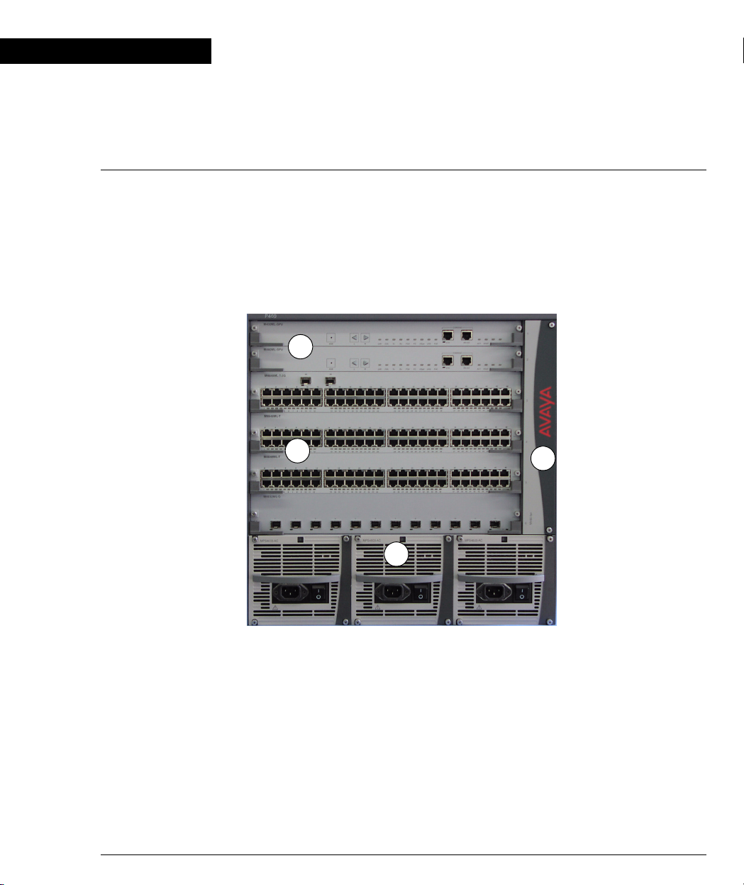
The Avaya P460 is a high-performance multilayer modular switch with two
Supervisor module slots, four I/O slots and up to three Power Supply Units. It
features full redundancy from switching fabric to port level.
Figure 1.1 The Avaya P460 Switch – Front View
1
2
Key
1 Supervisor modules
2 I/O modules
3 PSUs
4 Fan module
4
3
Avaya P460 Configuration Guide 1
Page 12

Chapter 1 Avaya P460 Product Overview
Avaya P460 Main Components
Note: For information on Installation, Troubleshooting and Maintenance of these
components, refer to the “Avaya P460 Installation and Maintenance Guide.”
Supervisor Modules
The P460 Supervisor modules form the core of the P460. Their functions include:
• Chassis-wide controlling
• I/O module initialization
• Switching fabric initialization
• Switching
• Layer 3 functionality, including routing
• SNMP management agent
• PSU & fan monitoring
• Power budgeting and management
• User interface
• Management interface
I/O Modules
The I/O modules provide the connections to your network devices, such as
workstations, printers, servers and other switches.
The I/O modules include:
Name Description
M4648ML-T 48 10/100 Mbps ports
M4648ML-T-2G 48 10/100 Mbps + 2 SFP GBIC ports
M4612ML-G 12 SFP GBIC ports
PSUs (Power Supply Units)
You can install up to three PSUs in a P460 chassis. Each PSU is equipped with a
cooling fan, an AC power entry filter module, an on/off switch and a status LED.
2 Avaya P460 Configuration Guide
Page 13
Chapter 2
Establishing Switch Access
Introduction
This chapter describes how to access the Avaya P460 CLI from the following
devices:
• A terminal to the serial port on the Supervisor Module
• A workstation running a Telnet session connected via an I/O module (Inband)
• A workstation running a Telnet session connected to the Console Fast Ethernet
port on a Supervisor module (outband)
• A remote terminal/workstation attached via a modem (PPP connection) to the
Supervisor Console Serial port. (Sideband)
Establishing a Console Connection with the P460
Figure 2.1 M460ML-SPV Supervisor Module Serial Console Port
Perform the following steps to connect a terminal to the P460 Serial Console port for
configuration of switch parameters:
1 Use the serial cable supplied to attach the RJ-45 console connector to the
Console port of the active M460ML-SPV module. Connect the DB-9 connector to
the serial (COM) port on your PC/terminal.
L The active Supervisor module is indicated by the ACT and OPR LEDs being lit.
2 Ensure that the serial port settings on the terminal are:
— 9600 baud
—8 bits
—1 stop bit
—no parity.
X If you reset or powered up the switch after connecting and configuring the
terminal, Welcome to P460 appears followed by the Login Name prompt.
L If the login prompt does not appear, press a key on the terminal.
3 Enter the default login: root.
X The Password prompt appears
4 Enter the user level password: root.
Avaya P460 Configuration Guide 3
Page 14

Chapter 2 Establishing Switch Access
Note: If you connect your terminal to the Standby SPV, you can get access to all the
CLI commands by opening a Session to the Active SPV.
Establishing a Telnet Connection with the Switch (Inband)
Perform the following steps to establish a Telnet connection to the P460 for
configuration:
L You need to assign an inband interface IP address using a direct connection to
the console serial port before you can establish the Telnet session.
1 Connect your station to the I/O module (directly or via the network).
2 Verify that you can communicate with the P460 using Ping to the inband
interface IP of the P460. If there is no response using the Ping command, check
the IP address and default gateway of both the P460 and the station.
L The default subnet mask is 255.255.255.0.
3 Start a Telnet session:
— From the Microsoft Windows
or access the command prompt
— Start the Telnet session by typing: telnet <P460_IP_address>
For example: telnet 149.49.35.214
X The Login Name prompt is displayed
4 Enter the default name root
X The password prompt is displayed
5 Enter the password root in lower case letters.
L You can now configure the P460.
®
taskbar of your PC click Start and then Run
Inband Interface Connection CLI Commands
In order to... Use the following command...
Configure the management
interface
Configure the management VLAN
ID
Enable the inband interface enable interface inband
Disable the inband interface disable interface inband
Display information on the device
network interfaces
4 Avaya P460 Configuration Guide
set interface inband
set inband vlan
show interface
Page 15

Chapter 2 Establishing Switch Access
In order to... Use the following command...
Send an ICMP echo request packets
to another node on the network.
Note: For more detailed information on the CLI commands, please refer to the
Avaya P460 Reference Guide
ping
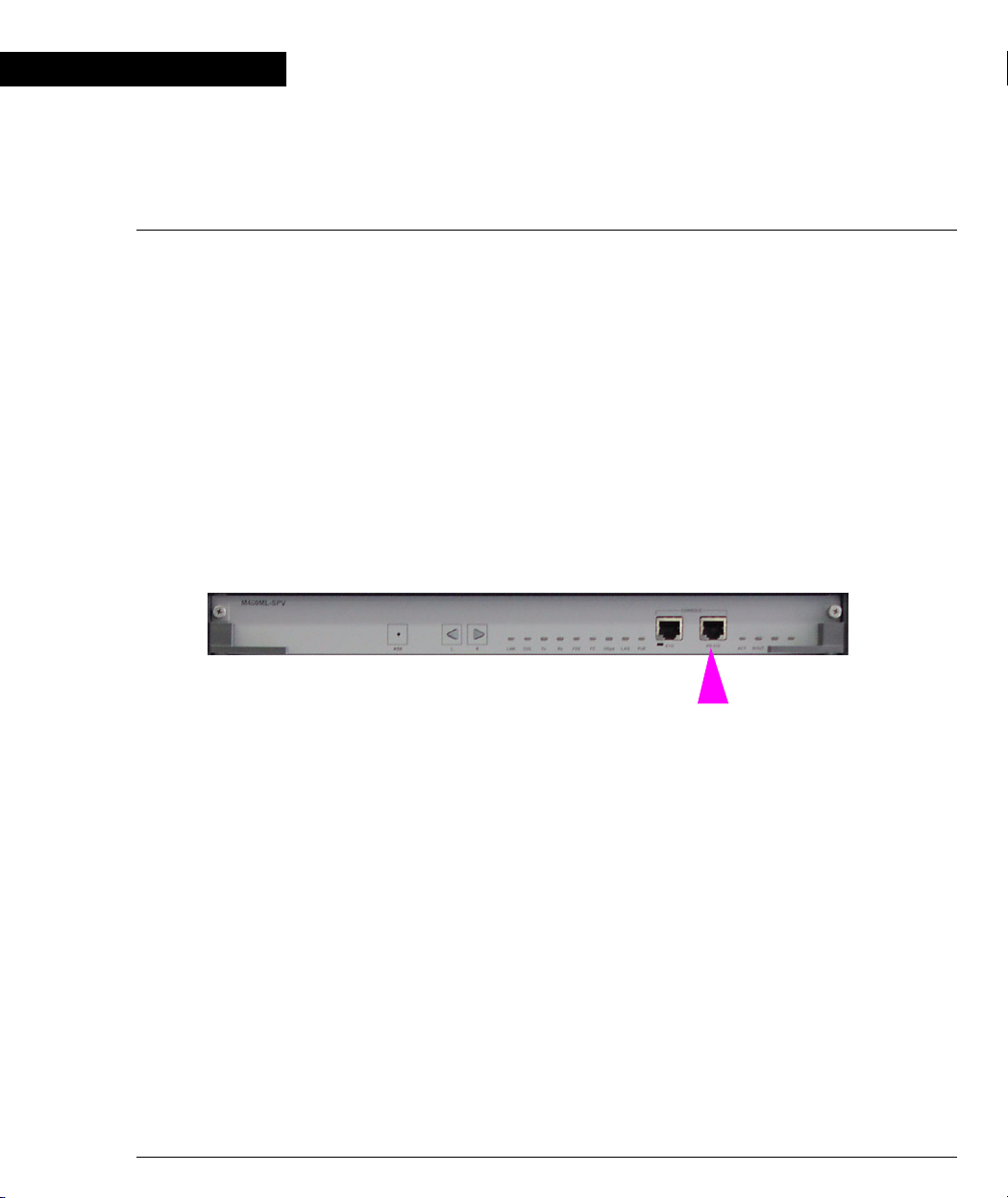
Establishing a Telnet Connection with the Switch (Outband)
Figure 2.2 M460ML-SPV Supervisor Module Fast Ethernet Console Port
Perform the following steps to establish a Telnet connection to the P460 for
configuration:
L You need to assign an outband interface IP address using a direct connection to
the console serial port before you can establish the Telnet session.
L You can configure the Fast Ethernet console port parameters if necessary.
L The outband interface should be on a different subnet from the inband interface.
1 Connect your station to the Fast Ethernet console port (directly or via the
network).
2 Verify that you can communicate with the P460 using “ping” to the outband
interface IP of the P460. If there is no response using the Ping command, check
the IP address and default gateway of both the P460 and the station.
3 Start a Telnet session:
— From the Microsoft Windows
or access the command prompt
— Start the Telnet session by typing: telnet <P460_IP_address>
For example: telnet 149.49.35.214
X The Login Name prompt is displayed
4 Enter the default name root
X The password prompt is displayed
5 Enter the password root in lower case letters.
L You can now configure the P460.
L You can connect the Out-band interface to either of the Supervisor modules.
®
taskbar of your PC click Start and then Run
Avaya P460 Configuration Guide 5
Page 16

Chapter 2 Establishing Switch Access
Outband Interface Connection CLI Commands
In order to... Use the following command...
Configure the management
set interface outband
interface
Enable the outband interface enable interface outband
Disable the outband interface disable interface outband
Enable or disable the link
set outband negotiation
negotiation protocol on the Fast
Ethernet console port
Set the speed of Fast Ethernet
set outband speed
Console port
Set the duplex mode of the Ethernet
set outband duplex
Console port
Display information on the device
show interface
network interfaces
Display outband interface
show outband
parameters
Send an ICMP echo request packets
ping
to another node on the network.
6 Avaya P460 Configuration Guide
Page 17
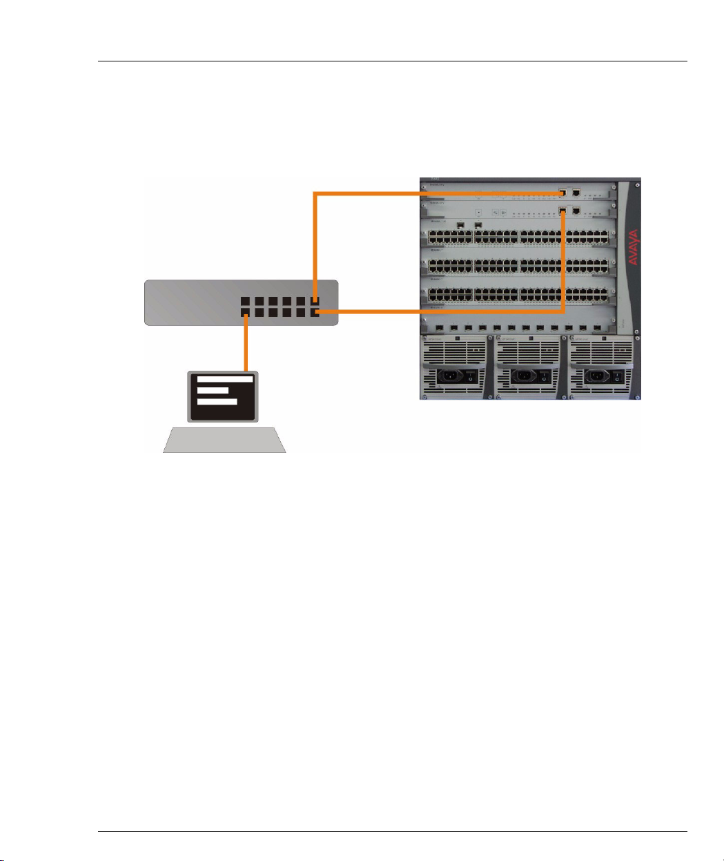
Redundant Outband Connections
You can create a redundant outband management connection by connecting both
Supervisor modules to the NMS via the Fast Ethernet interface by a switch (see
Figure 2.3).
Figure 2.3 Redundant Outband Connections
Switch
Workstation
Chapter 2 Establishing Switch Access
In this configuration, the Active SPV will respond to its Out-band port and the port
of the other SPV will be ignored.
Avaya P460 Configuration Guide 7
Page 18

Chapter 2 Establishing Switch Access
Establishing a PPP via Modem Connection with the P460 (Sideband)
Overview
The Point-to-Point Protocol (PPP) provides a Layer 2 method for transporting multiprotocol datagrams over point-to-point links. Here only IP datagrams will be
exchanged, over a RS232 serial connection, between the P460 supervisor module
and a remote peer (such as Ethernet) via a modem and the telephone lines. This
provides remote access the sideband management interface of a P460 via a modem.
Sideband (PPP) Interface CLI Commands
In order to... Use the following command...
Configure the device ppp interface
and control a PPP session
Configure the shared secret used in
PPP sessions with CHAP
authentication
Set the time after which the system
automatically disconnects an idle
PPP incoming session
Define the PPP authentication
method
Set the baud rate used in PPP
sessions
Display the PPP parameters of the
active PPP session.
Display the authentication method
used for PPP sessions
Display the time after which the
system automatically disconnects
an idle PPP incoming session
set interface ppp
set ppp chap-secret
set ppp incoming timeout
set ppp authentication incoming
set ppp baud-rate
show ppp session
show ppp authentication
show ppp incoming timeout
Display the baud rate used in PPP
sessions
Display the ppp configuration show ppp configuration
8 Avaya P460 Configuration Guide
show ppp baud-rate
Page 19

Setting Up Sideband (PPP) Connection Configuration
L You need to configure an IP address and netmask for the sideband interface
before you can establish a ppp link.
1 Connect a terminal to the Serial console port.
2 When you are prompted for a Login Name, enter the default name root.
3 When you are prompted for a password, enter the password root. You are
now in Supervisor Level.
4 At the prompt, type:
set interface ppp <ip_addr><net-mask>
with an IP address and netmask to be used by the Avaya P460 Supervisor
module to connect via its PPP interface.
L The PPP interface you configure with the set interface ppp command must be
on a different subnet from the inband and outband interfaces.
5 Set the baud rate, ppp authentication, and ppp time out required to match your
modem. These commands are described in the “Command Line Interface”
chapter.
6 At the prompt, type:
set interface ppp enable
X The following is displayed:
Entering the Modem mode within 60 seconds...
Please check that the proprietary modem cable is plugged
into the console port
7 Use the DB-25 to RJ-45 connector to plug the console cable to the modem’s DB-
25 connector. Plug the other end of the cable RJ-45 connector to an
Avaya P460 Supervisor module RJ-45 port.
8 The Avaya P460 Supervisor module enters modem mode.
9 You can now dial into the switch from a remote station, and open a Telnet, ping
or SNMP management session to the PPP interface IP address.
LIf you have two Supervisor modules installed, you can make a serial connection
to one SPV and configure the PPP parameters through one session and deploy
the PPP connection on the second Supervisor module.
Chapter 2 Establishing Switch Access
Avaya P460 Configuration Guide 9
Page 20

Chapter 2 Establishing Switch Access
10 Avaya P460 Configuration Guide
Page 21

Chapter 3
Avaya P460 Supervisor Module Features
Introduction
The Avaya P460 Supervisor module provides the following functionality:
• Chassis-wide control
• I/O module initialization
• Fabric initialization
• Switching that also uses also the fabric of the second SPV
• Layer 3 functionality including routing
• SNMP Management agent
• PSU & Fans monitoring
• Power Budgeting & Management
• User interface
• Management interface
At least one SPV is essential for the switch operation. When two SPVs are installed,
one serves as the active, while the other one is a stand-by.
The switching fabric of a standby Supervisor module actively participates in packet
switching/routing even when its CPU is inactive.
M460ML-SPV Supervisor Module Modes:
• Active – The Supervisor Module is operating
• Standby – This Supervisor Module is fully synchronized with the Active one and
can replace it in the case of failure.
• Halted – This Supervisor Module is not synchronized with the Active one and
cannot act as a standby module.
You can verify the Supervisor Module mode by:
• The ACT and OPR LED status (refer to Table 3.1),
• The show SPV CLI using the command, or
• The P460 Manager
Table 3.1 ACT and OPR LED Summary
ACT LED is... OPR LED is... M460ML-SPV Module mode
ON ON Active
Avaya P460 Configuration Guide 11
Page 22

Chapter 3 Avaya P460 Supervisor Module Features
Table 3.1 ACT and OPR LED Summary
ACT LED is... OPR LED is... M460ML-SPV Module mode
ON Blinking Active
OFF ON Standby
OFF Blinking Halted or booting
Supervisor Synchronization
Configuring the Supervisor Modules for Active/Standby Operation
In order to operate in an Active-Standby configuration, the two SPVs must be
synchronized.
• If the SPVs are not synchronized, one is Active and the other Halted.
In this case you will need to synchronize them manually. See “Synchronizing
the Supervisor Modules Manually“ on page 12.
• Only in Active-Standby configuration do both SPV fabrics participate in
switching/routing
• An SPV which was Active stays Active after a chassis reset
One of the SPVs can operate as Standby automatically only if both of the following
conditions are fulfilled:
• The current chassis is the last one in which you inserted this SPV
• The current running SW images are the same version
No fan module present
Synchronizing the Supervisor Modules Manually
If the SPVs are not synchronized, you need to synchronize them manually using the
Avaya P460 CLI.
Note: Synchronization can be required for a complete synchronization also if the
SPVs are in an Active-Standby configuration. For example, when the SPVs boot
with the same SW but from different banks
1 Access the CLI. See Chapter 2, “Establishing Switch Access“
2 Enter the sync spv command from the Active Supervisor Module.
L This command transfers the following information from the Active Supervisor
module to the other Supervisor module.
— Firmware images
12 Avaya P460 Configuration Guide
Page 23

Chapter 3 Avaya P460 Supervisor Module Features
— Embedded Web image
— Preferred boot bank
— Chassis synchronization
L The transfer process can take up to 90 seconds.
L The following screen capture shows the process:
P460-1(super)# sync spv
This command may overwrite the neighbor SPV software and
reset both SPVs
*** Confirmation *** - do you want to continue (Y/N)? y
Copying Bank A to the neighbor SPV ...
Copying Bank A to the neighbor SPV done
Copying Bank B to the neighbor SPV ...
Copying Bank B to the neighbor SPV done
Copying Embedded Web image to the neighbor SPV ...
Copying Embedded Web image to the neighbor SPV done
Setting boot bank of the neighbor SPV ...
Setting boot bank of the neighbor SPV done
Setting chassis sync on for the neighbor SPV...
Setting chassis sync on for the neighbor SPV done
SPVs are resetting.
Please wait till the process is finished. The SPVs will be
synchronized after the reset is completed
Note: After the transfer is finished, the Supervisor Modules are reset automatically.
— After the reset the configuration files of the Active Supervisor Module will
be copied to the Standby Supervisor Module.
L This process can take up to two minutes.
Configuration File Synchronization
Three configuration files are stored in the Supervisor module flash memory:
• Layer 2 configuration (L2-config)
• Layer 3 running configuration (running-config)
• Layer 3 startup configuration (startup-config)
If SPVs are present, the configuration is automatically synchronized between the
Active and Standby Supervisor modules.
• Initial configuration synchronization takes place after the boot: this process can
take up to thirty seconds.
Avaya P460 Configuration Guide 13
Page 24

Chapter 3 Avaya P460 Supervisor Module Features
• Layer 2 configuration changes are saved in both Supervisor modules when you
press Enter.
L The Supervisor module Ethernet outband interface configuration is not
synchronized between the modules.
• Layer 3 startup configuration is saved in the Standby SPV when you execute the
copy running-config startup-config CLI command. This
configuration is also saved in the Active SPV
L The Layer 3 running configuration is not saved in the Standby SPV
14 Avaya P460 Configuration Guide
Page 25

Chapter 4
Avaya P460 Layer 2 Features
Ethernet
Ethernet is one of the most widely implemented LAN standards.
It uses the Carrier Sense Multiple Access with Collision Detection (CSMA/CD)
access method to handle simultaneous demands. CSMA/CD is a multi-user
network allocation procedure in which every station can receive the transmissions
of any other station. Each station waits for the network to be idle before transmitting
and each station can detect collisions by other stations.
The first version of Ethernet supported data transfer rates of 10 Mbps, and is
therefore known as 10BASE-T.
Fast Ethernet€
Fast Ethernet is a newer version of Ethernet, supporting data transfer rates of 100
Mbps. Fast Ethernet is similar enough to Ethernet to support the use of most current
Ethernet applications and network management tools. Fast Ethernet is also known
as 100BASE-T (over copper) or 100BASE-FX (over fiber).
Fast Ethernet is standardized as IEEE 802.3u.
Gigabit Ethernet€
Gigabit Ethernet supports data rates of 1 Gbps. It is also known as 1000BASE-T
(over copper) or 1000BASE-FX (over fiber).
Gigabit Ethernet is standardized as IEEE 802.3z.
Configuring Ethernet Parameters
Auto-negotiation€
Auto-Negotiation is a protocol that runs between two stations, two switches or a
station and a switch. When enabled, Auto-Negotiation negotiates port speed and
duplex mode by detecting the highest common denominator port connection for the
endstations. For example, if one workstation supports both 10 Mbps and 100 Mbps
speed ports, while the other workstation only supports 10 Mbps, then AutoNegotiation sets the port speed to 10 Mbps.
For Gigabit ports, Auto-Negotiation determines the Flow Control configuration of
the port.
Avaya P460 Configuration Guide 15
Page 26

Chapter 4 Avaya P460 Layer 2 Features
The Avaya P460 supports auto-negotiation enabling/disabling on a per-port basis.
Flow Control€
Flow Control ensures that the receiving device can handle all the incoming data.
Flow control does this by adjusting the data flow from one device to another. This is
particularly important where the sending device can send data much faster than the
receiving device can receive the data.
There are many flow control mechanisms. One of the most common flow control
protocols for asynchronous communication is called xon-xoff. In this case, the
receiving device sends a an xoff message to the sending device when its buffer is
full. The sending device then stops sending data. When the receiving device is ready
to receive more data, it sends an xon signal.
Flow control can be implemented in hardware or software, or a combination of
both. The P460 uses hardware flow control.
Duplex Mode€
Devices that support full-duplex can transmit and receive data simultaneously.
Half-duplex transmission where each device can only communicate in turn.
Full-duplex provides higher throughput than half-duplex.
The Avaya P460 supports both full duplex and half duplex.
Speed€
The IEEE defines three standard speeds for Ethernet: 10, 100 and 1000 Mbps, also
known as Ethernet, Fast Ethernet and Gigabit Ethernet respectively.
The Avaya P460 supports the following port speeds:
• 10/100 Mbps
• 1000 Mbps
MAC Address€
The MAC address is a unique 48-bit value associated with any network adapter.
MAC addresses are also known as hardware addresses or physical addresses. They
uniquely identify an adapter on a LAN.
MAC addresses are 12-digit hexadecimal numbers (48 bits in length). By
convention, MAC addresses are usually written in one of the following two formats:
• MM:MM:MM:SS:SS:SS
• MM-MM-MM-SS-SS-SS
The first half of a MAC address contains the ID number of the device manufacturer.
An Internet standards body regulates these IDs. The second half of a MAC address
represents the serial number assigned to the device by the manufacturer.
16 Avaya P460 Configuration Guide
Page 27

CAM Table€
It might be inefficient if the Avaya P460 could not “remember” which MAC address
was accessible from which port, that is, where a specific device is attached.
Therefore, the P460 stores a mapping of learned MAC addresses to port and VLANs
in the CAM table. The switch then checks subsequent frames. If the MAC address
appears in the CAM Table, then the packet is forwarded to the appropriate port.
If the MAC address does not appear in the CAM table, or the MAC Address
mapping has changed, then the frame is duplicated and copied to all the ports. Once
a reply is received, the CAM table is updated with the new address/VLAN port
mapping.
The CAM table size in the Avaya P460 is a minimum of 4k and a maximum of 8k.
Ethernet Configuration CLI Commands
In order to... Use the following command...
Chapter 4 Avaya P460 Layer 2 Features
Set the auto negotiation mode of a
set port negotiation
port
Administratively enable a port set port enable
Administratively disable a port set port disable
Set the speed for a 10/100 port set port speed
Configure the duplex mode of a
set port duplex
10/100BASE-T port
Configure a name for a port set port name
Set the send/receive mode for flow-
set port flowcontrol
control frames on a full duplex port
Set the flow control advertisement
for a Gigabit port when performing
set port auto-negotiationflowcontrol-advertisement
autonegotiation
Display settings and status for all
show port
ports
Display per-port status information
show port flowcontrol
related to flow control
Display the flow control
advertisement for a Gigabit port
show port auto-negotiationflowcontrol-advertisement
used to perform auto-negotiation
Avaya P460 Configuration Guide 17
Page 28

Chapter 4 Avaya P460 Layer 2 Features
In order to... Use the following command...
Display the CAM table entries for a
show cam
specific port
Clear all the CAM entries. clear cam
Send ICMP echo request packets to
ping
another node on the network.
18 Avaya P460 Configuration Guide
Page 29

Ethernet Configuration Examples
This example shows basic Ethernet configuration for port 40 on I/O module 6:
1 Disabling port negotiation
P460-1(super)# set port negotiation 6/40 disable
Link negotiation protocol disabled on port 6/40
2 Setting port duplex to full
P460-1(super)# set port duplex 6/40 full
Port 6/40 speed set to full duplex
3 Setting port speed to 100 Mbps
P460-1(super)# set port speed 6/40 100mb
Port 6/40 speed set to 100MBps
Chapter 4 Avaya P460 Layer 2 Features
4 Enabling port negotiation
P460-1(super)# set port negotiation 6/40 enable
Link negotiation protocol enabled on port 6/40
Avaya P460 Configuration Guide 19
Page 30

Chapter 4 Avaya P460 Layer 2 Features
VLAN Configuration
VLAN Overview
A VLAN is made up of a group of devices on one or more LANs that are
configured so the devices operate as if they form an independent LAN. These
devices can, in fact, be located on several different LAN segments. VLANs can be
used to group together departments and other logical groups, thereby reducing
network traffic flow and increasing security within the VLAN.
Figure 4.1 illustrates how a simple VLAN can connect several endpoints in different
locations and attached to different hubs. In this example, the Management VLAN
consists of stations on numerous floors of the building which are connected to both
Device A and Device B.
Figure 4.1 VLAN Overview
In virtual topological networks, the network devices can be located in diverse places
around the LAN. These devices can be in different departments, on different floors
or in different buildings. Connection is achieved through software. Each network
device is connected to a hub, and the network manager uses management software
to assign each device to a virtual topological network. Elements can be combined
into a VLAN even if they are connected to different devices.
You can use VLANs whenever there are one or more groups of network users that
you want to separate from the rest of the network.
20 Avaya P460 Configuration Guide
Page 31

Chapter 4 Avaya P460 Layer 2 Features
In Figure 4.2, the switch has three separate VLANs: Sales, Engineering, and
Marketing. Each VLAN has several physical ports assigned to it with PC’s
connected to those ports. When traffic flows from a PC on the Sales VLAN, for
example, that traffic is only forwarded out the other ports assigned to that VLAN.
Thus, the Engineering and Mktg VLANs are not burdened with processing that
traffic.
Figure 4.2 VLAN Switching and Bridging
VLAN Tagging
Sales
Marketing
Sales
Engineering
Marketing
Engineering
VLAN Tagging is a method of controlling the distribution of information on the
network. The ports on devices supporting VLAN Tagging are configured with the
following parameters:
• Port VLAN ID
• Tagging Mode
The Port VLAN ID is the number of the VLAN to which the port is assigned.
L You need to create a VLAN with the set vlan command before you can
assign it to a port.
Untagged frames and frames tagged with VLAN 0 entering the port are assigned
the port's VLAN ID. Tagged frames are unaffected by the port's VLAN ID.
The Tagging Mode determines the behavior of the port that processes outgoing
frames:
• If Tagging Mode is set to “Clear”, the port transmits frames that belong to the
port's VLAN table. These frames leave the device untagged.
• If Tagging Mode is set to “IEEE-802.1Q”, all frames keep their tags when they
leave the device. Frames that enter the switch without a VLAN tag are tagged
with the VLAN ID of the port they entered through.
Avaya P460 Configuration Guide 21
Page 32

Chapter 4 Avaya P460 Layer 2 Features
Multi VLAN Binding
Multi VLAN binding, also known as Multiple VLANs per port, allows access to
shared resources by stations that belong to different VLANs through the same port.
This is useful in applications such as multi-tenant networks, where each user has his
or her own VLAN for privacy. The whole building has a shared high-speed
connection to the ISP.
In order to accomplish this, the P460 enables multiple VLANs per port. The three
available Port Multi-VLAN binding modes are:
• Bound to All - the port is programmed to support the entire 4K VLANs range.
Traffic from any VLAN is forwarded through a port defined as “Bound to All”.
This is intended mainly for easy backbone link configuration
• Bound to Configured - the port supports all the VLANs configured in the
switch. These may be either PVIDs (Port VLAN IDs) or VLANs that were
manually added to the switch.
• Statically Bound - the port supports VLANs manually configured on it.
Figure 4.3 shows these binding modes.
Figure 4.3 Multiple VLAN Per-port Binding Modes
Static Binding
-
The user manually specifies
the list of VLAN IDs to be
bound to the port, up to 250
VLANs
-
Default mode for all ports
-
Only VLAN 9, and any other
VLANs statically configured
on the port will be allowed to
access this port
Bind to Configured
- The VLAN table of the port will
Bind to All
- Any VLAN in the range of 14080 are allowed access
through this port
- Intended mainly for easy
backbone link configuration
support all the Static VLAN entries and
all the ports’ VLAN IDs (PVIDs)
present in the switch
- VLANs 1,3,5,9,10 coming from the bus
are allowed access through this port
- All the ports in Bound to Configured
mode support the same list of VLANs
22 Avaya P460 Configuration Guide
Page 33

P460 VLAN Table
The P460 VLAN table includes two types of VLANs:
• User-configured VLANs
• Dynamically learnt from the incoming traffic on the “Bind to All” ports
When the VLAN list reaches its maximum capacity it is locked. No VLANs are
dynamically learned and it is not be possible to configure more VLANs manually.
If this occurs, use the clear dynamic vlans CLI
VLAN list.
Any new VLAN, either configured by you or learnt from incoming traffic, are made
known to all the modules in the system.
The P460 supports up to 250 VLANs in the table, both user-defined and dynamic.
Ingress VLAN Security
The Avaya P460 allows only packets tagged with VLANs that are configured on a
specific port are permitted to enter the through that port. Ingress VLAN Security
therefore allows easy implementation of security.
VLAN CLI Commands
Chapter 4 Avaya P460 Layer 2 Features
command to free space in the
In order to... Use the following command...
Assign the Port VLAN ID (PVID) set port vlan
Define the port binding method set port vlan-binding-mode
Define a static VLAN for a port set port vlan
Configure the tagging mode of a
set trunk
port
Create VLANs set vlan
Display the port VLAN binding
show port vlan-binding-mode
mode settings
Display VLAN tagging information
show trunk
of the ports, port binding mode,
port VLAN ID and the allowed
VLANs on a port
Display the VLANs configured in
show vlan
the switch.
Avaya P460 Configuration Guide 23
Page 34

Chapter 4 Avaya P460 Layer 2 Features
In order to... Use the following command...
Display dynamically learned
show dynamic vlans
VLANs
Clear VLAN entries clear vlan
Clear a VLAN statically configured
clear port static-vlan
on a port
Clear dynamic vlans
clear dynamic vlans
Only the VLANs learned by the switch
from incoming traffic on the “bind to
all” ports are cleared using this
command
24 Avaya P460 Configuration Guide
Page 35

VLAN Configuration Example
This example shows VLAN configuration for port 40 on I/O module on I/O
module 6:
1 Defining VLAN 10 (switch-level)
P460-1(super)# set vlan 10
VLAN ID 10 created
2 Assigning VLAN 10 to port 40 on I/O module 6
P460-1(super)# set port vlan 10 6/40
VLAN 10 modified.
VLAN Mod/Ports
---- ---------
10 6/40
3 Setting the port to “bind to configured” mode
Chapter 4 Avaya P460 Layer 2 Features
P460-1(super)# set port vlan-binding-mode 6/40 bind-toconfigured
Set Port Vlan binding method:6/40
4 Assigning static vlan 22 to the port
P460-1(super)# set port static-vlan 6/40 22
VLAN 22 is bound to port 6/40
5 Displaying the VLAN configuration for the port
P460-1(super)# sh trunk 6/40
Port Mode Binding mode Native vlan Vlans allowed on trunk
----- ---- ---- ------------------------------------ ----------- -------
6/40 dot1q bound to configured vlans 10 1-3,10,22
L Ports 1 to 3 were already defined on the switch so were bound automatically to
the port by the “bind-to-configured” CLI command
Avaya P460 Configuration Guide 25
Page 36

Chapter 4 Avaya P460 Layer 2 Features
Spanning Tree Configuration
Spanning Tree Overview
Without Spanning Tree a Network might experience packet storms when there are
multiple bridges and paths through the network. In addition, loops might be
formed in the network. When there are loops in the network Bridges see more than
one path to the same device. Packet storms and loops can cause a network to slow to
a crawl, and eventually bring the network down.
The spanning tree algorithm creates a single path through the network. The
algorithm ensures that if more than one path exists between two parts of the
network, only one of these paths is used, while the other is blocked.
The Spanning Tree Algorithm:
• Produces a logical tree topology out of any arrangement of bridges. The result is
a single path between any two end stations on an extended network.
• Provides a high degree of fault tolerance. It allows the network to automatically
reconfigure the spanning tree topology if there is a bridge or data-path failure.
The Spanning Tree Algorithm requires five values to derive the spanning tree
topology. These are:
1 A multicast address specifying all bridges on the extended network. The
software automatically determines the media-dependent address.
2 A network-unique identifier for each bridge on the extended network.
3 A unique identifier for each bridge/LAN interface (a port).
4 The relative priority of each port.
5 The cost of each port.
After these values are assigned, bridges multicast and process the formatted frames,
called Bridge Protocol Data Units, or BPDUs, to derive a single, loop-free topology
throughout the extended network. The bridges exchange BPDU frames quickly,
minimizing the time that service is unavailable between hosts.
Spanning Tree per Port
The STA can take up to 30 seconds to execute which might cause problems on ports
carrying time-sensitive traffic. You can therefore enable/disable Spanning Tree on a
per-port basis to minimize this effect.
26 Avaya P460 Configuration Guide
Page 37

Spanning Tree CLI Commands
In order to... Use the following command...
Chapter 4 Avaya P460 Layer 2 Features
Enable/Disable the spanning-tree
set spantree enable/disable
protocol for the switch
Set the bridge priority for STA set port spantree priority
Enable/Disable the spanning tree
set port spantree
for switch ports
Set the port spantree priority level set port spantree priority
Set the cost of a port set port spantree cost
Display Spanning Tree Protocol
show spantree
(STP) settings
Avaya P460 Configuration Guide 27
Page 38

Chapter 4 Avaya P460 Layer 2 Features
LAG Configuration
LAG Overview
A LAG uses multiple ports to create a high bandwidth connection with another
device. For example, assigning four 100BASE-T ports to a LAG on an M4648ML-T
I/O module, allows the module to communicate at an effective rate of 400 Mbps
with another switch.
LAGs provide a cost-effective method for creating a high bandwidth connection.
LAGs also provide built-in redundancy for the ports that belong to a LAG. If a port
in a LAG fails, another port in the LAG handles its traffic .
To create a LAG, you must select a base port. The behavior of the LAG is derived
from the base port. The attributes of the base port, such as port speed, VLAN
number, etc., are applied to the other ports in the LAG.
When created, each LAG is automatically assigned a logical port number. You can
then use this logical port number for all configuration required for the LAG, such as
Spanning Tree, Redundancy, and so on.
Configuring LAGs
L You can only create LAGs by combining the same port types on the same I/O
Module.
L Table 3.1 summarizes possible LAG configurations:
Table 4.1 Possible LAG Configurations
Module Maximum
number of
LAGs
M4648ML-T 6 10/100
M4648ML-T-2G 6 10/100
1 GBIC GBIC
28 Avaya P460 Configuration Guide
Base port
is...
Mbps
Mbps
Additional ports
must be...
10/100 Mbps
Part of the same
group of 24 ports
(1-24; 25-28)
10/100 Mbps
Part of the same
group of 24 ports
(1-24; 25-28)
On same the
module
Logical port
numbers
101-103
(ports 1-24)
104-106
(ports 25-48)
101-103
(ports 1-24)
104-106
(ports 25-48)
107
Page 39

Table 4.1 Possible LAG Configurations
Chapter 4 Avaya P460 Layer 2 Features
Module Maximum
M4612ML-G 6 GBIC GBIC
Logical Port Numbers
The logical port number is used to identify the LAG. For example, if you define one
LAG containing ports 1 to 3 on an M4612ML-G module, the LAG has the logical
port number 101.
This is useful for port configuration commands and port redundancy among other
features.
LAG Redundancy
See Port Redundancy Configuration on page 31.
number of
LAGs
Base port
is...
Additional ports
must be...
Part of the same
group of six ports
(1-6; 7-12)
Logical port
numbers
101-103
(ports 1-6)
104-106
(ports 7-12)
Avaya P460 Configuration Guide 29
Page 40

Chapter 4 Avaya P460 Layer 2 Features
LAG CLI Commands
In order to... Use the following command...
Enable or disable a Link
Aggregation Group interface on the
switch
Display Link Aggregation Group
information for a specific switch or
port
LAG Configuration Example
This example shows definition of a LAG called “p460lag” using ports 41 to 47 on
I/O module 6:
P460-1(super)# set port channel 6/41-47 on p460lag
Port 6/41 channel mode set to on
Port 6/42 was added to channel
Port 6/43 was added to channel
Port 6/44 was added to channel
Port 6/45 was added to channel
Port 6/46 was added to channel
Port 6/47 was added to channel
L Port 41 is the base port
set port channel
show port channel
30 Avaya P460 Configuration Guide
Page 41

Port Redundancy Configuration
Port Redundancy Overview
Redundancy involves the duplication of devices, services, or connections, so, in the
event of a failure, the redundant duplicate can take over for the one that failed.
Since computer networks are critical for business operations, it is vital to ensure that
the network continues to function even if a piece of equipment fails. Even the most
reliable equipment might fail on occasion, but a redundant component can ensure
that the network continues to operate despite such failure.
Along with Link Aggregation Groups, which provide basic redundancy, the P460
offers an additional port redundancy scheme.
To achieve port redundancy, you can define a redundancy relationship between any
two ports in a switch. One port is defined as the primary port and the other as the
secondary port. If the primary port fails, the secondary port takes over.
You can configure up to 32 pairs of ports or LAGs per chassis: each pair contains a
primary and secondary port or LAG. You can configure any type of port to be
redundant to any other.
Secondary Port Activation
The secondary port takes over within one second and is activated when:
• The Primary port link not functioning
• The Primary port I/O module is removed
• The Primary port I/O module failed because of power down, hardware failure,
and so on.
• Subsequent switchovers take place after the "min-time-between-switchovers"
has elapsed.
Chapter 4 Avaya P460 Layer 2 Features
Switchback
When the Primary port recovers a switch-back takes place if you have not disabled
this in management.
Switchback Parameters
• “min-time-between-switchovers” - minimum time that is allowed to elapse
before a Primary-Backup switchover
• “switchback-interval” – the minimum time the Primary port link has to be up
before a switch-back to the Primary port takes place. If you set this to “never”,
there is no switch-back to the Primary port when it recovers.
Avaya P460 Configuration Guide 31
Page 42

Chapter 4 Avaya P460 Layer 2 Features
Redundancy CLI Commands
In order to... Use the following command...
Define/delete a redundancy entry. set port redundancy (on/off)
Enable port redundancy on the
set port redundancy enable
switch
Disable port redundancy on the
set port redundancy disable
switch
Set the minimum time that is
set port redundancy-intervals
elapses before a Primary-Backup
switchover and the minimum time
the Primary port link has to be up
before a switch-back to the Primary
port takes place
Show port redundancy
show port redundancy
configuration
• When you remove an I/O module, the port redundancy configurations are
retained.
• If you replace the I/O module with the same type, redundancy will be reestablished.
• If you replace the I/O module with a different type, the redundancy
configuration will be restored to the default values.
• Any new redundancy definitions over-ride the retained configuration.
32 Avaya P460 Configuration Guide
Page 43

Port Redundancy Configuration Example
This example shows configuration of a port redundancy pair called “p460red”
between ports 40 and 48 on I/O module 6 and its configuration.
P460-1(super)# set port redundancy 6/40 6/48 on p460red
p460red: Port 6/48 is redundant to port 6/40
Port redundancy is active - entry is effective immediately
P460-1(super)# set port redundancy disable
All redundancy schemes are disabled but not removed
P460-1(super)# set port redundancy enable
All redundancy schemes are now enabled
P460-1(super)# set port redundancy-intervals 10 none
Done!
P460-1(super)# sh port redundancy
Redundancy Name Primary Port Secondary Port Status
--------------- -- -------------- ---------------p460red 6/40 6/48 primary
Chapter 4 Avaya P460 Layer 2 Features
Minimum Time between Switchovers: 10
Switchback interval: none
L When the user executes the set port redundancy disable command, the
redundancy is disabled but the definitions are saved.
Avaya P460 Configuration Guide 33
Page 44

Chapter 4 Avaya P460 Layer 2 Features
IP Multicast Filtering Configuration
Overview
IP Multicast is a method of sending a single copy of an IP packet to multiple
destinations. Different applications including video streaming and video
conferencing can use IP multicast.
The Multicast packet is forwarded from the sender to the recipients, duplicated only
when needed by routers along the way. The packet is sent in multiple directions
such that it reaches all the members of the Multicast group. Multicast addresses are
a special kind of IP addresses (class D), each identifying a multicast group. Stations
join and leave multicast groups using IGMP. This is a control-plane protocol
through which IP hosts register with their router to receive packets for certain
multicast addresses.
IP multicast packets are transmitted on LANs in MAC multicast frames. Traditional
LAN switches flood these multicast packets like broadcast packets to all stations in
the VLAN. In order to avoid sending multicast packets where they are not required,
multicast filtering functions can be added to the layer 2 switches. This is described
in the IEEE standard 802.1D. Layer 2 switches capable of multicast filtering send the
multicast packets only to ports connecting members of that multicast group. This is
usually based on IGMP snooping.
The Avaya P460 includes multicast filtering support. The P460 learns which switch
ports need to receive which multicast packets and configures the necessary
information into the switch's hardware tables. This learning is based on IGMP
(version 1 or 2) snooping. Using the learned information, IP multicast packets are
forwarded only to ports connecting members of that multicast group.
The multicast filtering function in the P460 is transparent to the IP hosts and routers.
It does not affect the forwarding behavior apart from filtering multicast packets
from certain ports where they are not needed. To the ports that do get the multicast,
forwarding is performed in the same way as if there was no filtering. The multicast
packet will not be sent to any ports that would not receive it if there was no filtering.
The multicast filtering function operates per VLAN. A multicast packet arriving at
the device on a certain VLAN is forwarded only to a subset of the ports of that
VLAN. If VLAN tagging mode is used on the output port, then the multicast packet
is tagged with the same VLAN number with which it arrived. This is interoperable
with multicast routers that expect Layer 2 switching to be done independently for
each VLAN.
IP Multicast Filtering configuration is associated with the setting up of three timers:
• The Router Port Pruning timer ages out Router port information if IGMP
queries are not received within the configured time.
• The Client Port Pruning time is the time after the P460 switch reset that the
filtering information is learned by the switch but not configured on the ports.
34 Avaya P460 Configuration Guide
Page 45

• The Group Filtering Delay time is the time that the switch should wait between
becoming aware of a Multicast group on a certain VLAN and starting to filter
traffic for this group.
IP Multicast CLI Commands
In order to... Use the following command...
Chapter 4 Avaya P460 Layer 2 Features
Enable or disable IP multicast
set intelligent-multicast
filtering
Define aging time for client ports set intelligent-multicast client port
pruning time
Define aging time for router ports set intelligent-multicast router port
pruning time
Define group filtering time delays set intelligent-multicast group-
filtering delay time
Display the IP multicast filtering
show intelligent-multicast
status
Avaya P460 Configuration Guide 35
Page 46

Chapter 4 Avaya P460 Layer 2 Features
Broadcast Storm Control
Broadcast Storm Control Overview
This feature allows you to protect the network or switch from excessive Broadcast
or Unknown traffic.
When the Broadcast Storm Control is enabled, the switch discards broadcast,
multicast and unknown packets when the Broadcast Threshold Rate on a switch
port exceeds a specified threshold. The Broadcast Threshold Rate is the number of
broadcast packets received by a port per second.
When you enable Broadcast Storm Control, counters are set on all 10/100 Mbps
ingress ports.
L Broadcast Storm Control is only supported on 10/100 Mbps I/O ports.
The P460 hardware includes separate counters for broadcast, multicast and
unknown packets. When any of these counters crosses the specified threshold, the
respective storm packets are dropped.
36 Avaya P460 Configuration Guide
Page 47

Broadcast Storm Control CLI Commands
In order to... Use the following command...
Chapter 4 Avaya P460 Layer 2 Features
Enable or disable broadcast storm
control.
Set the broadcast storm control
threshold (in packets per second)
Display broadcast storm
status and settings.
Broadcast Storm Control Configuration Examples
This example shows configuration of broadcast storm control with a threshold of
100,000 pps.
P460-1(super)# set broadcast storm enable
Broadcast storm control enabled
P460-1(super)# set broadcast storm threshold 100000
Broadcast storm threshold was set
P460-1(super)# sh broadcast storm control
Broadcast Threshold
Storm Control
--------------- -----------enabled 100000
set broadcast storm control
set broadcast storm control
threshold
show broadcast storm control
Avaya P460 Configuration Guide 37
Page 48

Chapter 4 Avaya P460 Layer 2 Features
Priority Configuration
Overview
By its nature, network traffic varies greatly over time, so short-term peak loads
might exceed the switch capacity. When this occurs, the switch must buffer frames
until there is enough capacity to forward them to the appropriate ports.
This, however, can interrupt time-sensitive traffic streams, such as Voice and other
converged applications. These packets need to be forwarded with the minimum of
delay or buffering. In other words, they need to be given high priority over other
types of network traffic.
Priority determines in which order packets are sent on the network and is a key part
of QoS (Quality of Service).
The IEEE standard for priority on Ethernet networks is 802.1p.
Priority Queues
Priority Configuration CLI Commands
In order to... Use the following command...
Set the priority level of a port set port level
Display priority settings and status
for all ports
38 Avaya P460 Configuration Guide
show port
Page 49

Chapter 5
Avaya P460 Layer 3 Features
Introduction
What is Routing?
Routing allows transfer of a data packet from source to destination by a device
called a router. Routing involves two basic activities: determination of optimal
routing paths and transmission of information packets through an internetwork.
Routers use routing tables to determine the routes to particular network
destinations and, in some cases, metrics associated with those routes. Routers
communicate with one another, and maintain their routing tables through the
transmission of a variety of messages. Routers can only route a message that is
transmitted by a routable protocol such as IP or IPX. Messages in non-routable
protocols, such as NetBIOS and LAT, cannot be routed, but they can be transferred
from LAN to LAN by a bridge.
The Routing Update Message is one such message. Routing Updates usually consist
of all or a portion of a routing table. By analyzing Routing Updates from all routers,
a router can build a detailed picture of network topology.
A Link-State Advertisement is another example of a message sent between routers.
Link-State Advertisements inform other routers of the state of the sender's links.
Link information can also be used to build a complete picture of the network's
topology. Once the network topology is understood, routers can determine optimal
routes to network destinations.
When a router receives a packet, it examines the packet's destination protocol
address. The router then determines whether it knows how to forward the packet to
the next hop. If the router does not know how to forward the packet, it usually
drops the packet unless a default gateway is defined. If the router knows how to
forward the packet, it changes the packet destination’s physical address to that of
the next hop and transmits the packet.
The next hop might not be the ultimate destination host. If not, the next hop is
usually another router, which executes the same switching decision process. While
the packet moves through the internetwork, its physical address changes but its
protocol address remains constant. This process is shown in Figure 5.1.
Avaya P460 Configuration Guide 39
Page 50

Chapter 5 Avaya P460 Layer 3 Features
Figure 5.1 Routing
First Hop
Protocol Address:Destination
Physical Address:Router 1
VMAC: 0005E000102 (VRID)
Main Router 1
VRID: 1, IP: 20.20.20.1=Ass. IP
VMAC: 00005E000101 (VRID)
Third Hop
Protocol Address:Destination
Physical Address:Destination
VMAC: 0005E000102 (VRID)
Main Router 1
VRID: 1, IP: 20.20.20.1=Ass. IP
VMAC: 00005E000101 (VRID)
Second Hop
Protocol Address:Destination
Physical Address:Router 2
VMAC: 0005E000102 (VRID)
Main Router 1
VRID: 1, IP: 20.20.20.1=Ass. IP
VMAC: 00005E000101 (VRID)
The routers obtain the relation between the destination host’s protocol address and
its physical address using the ARP request/reply mechanism.The information is
stored within the ARP table in the router. See “The ARP Table“ on page 55.
Within an enterprise, routers serve as an internet backbone interconnecting all
networks. This architecture strings several routers together by a high-speed LAN
topology such as Fast Ethernet or Gigabit Ethernet. Within the global Internet,
routers do all the packet switching in the backbones.
Another approach within an enterprise is the collapsed backbone. This uses a single
router with a high-speed backplane to connect the subnetworks, making network
management simpler and improving performance.
40 Avaya P460 Configuration Guide
Page 51

Routing Configuration
Forwarding
The P460 forwards IP packets between IP networks. When it receives an IP packet
through one of its interfaces, it forwards the packet through one of its interfaces. The
P460 supports multinetting. This allows it to forward packets between IP
subnetworks on the same VLAN and between different VLANs. Forwarding is
performed through standard means in Router mode.
Multinetting (Multiple Subnetworks per VLAN)
In Router Mode, most applications such as RIP and OSPF, operate per IP interface.
Other applications such as VRRP and DHCP/BOOTP Relay operate per VLAN.
Configuration of these applications is done in the Interface mode. When there is
only a single interface (subnetwork) per VLAN then system behavior is intuitive
since a subnet and a VLAN are the same.
If the configuration includes multiple interfaces (subnetworks) per VLAN things
start to get complicated.
For example, if there are two interfaces over the same VLAN and you configure
DHCP server on one interface, the DHCP server will be used also for the second
interface over the same VLAN. This behavior might be less expected and in some
cases wrong.
The P460 prevents configuration of VLAN-oriented commands on an interface
unless the user explicitly enables it, using the enable vlan commands CLI
command. This stops misconfiguration and unexpected results.
If there is only one interface over a VLAN, you can configure this VLAN through
the single interface without the need to issue the enable vlan commands
command.
Chapter 5 Avaya P460 Layer 3 Features
Note:
1. When you issue VLAN-oriented commands, the commands affect the VLAN of
the interface that was used at the time the you issued the command.
2. If the you move the interface is moved to another VLAN with the ip vlan/ip
vlan name CLI command, VLAN oriented configuration still applies to the
original VLAN.
Avaya P460 Configuration Guide 41
Page 52

Chapter 5 Avaya P460 Layer 3 Features
IP Configuration
IP Configuration CLI Commands
In order to... Use the following command...
Enable IP routing ip routing
Set ICMP error messages ip icmp-errors
Specify the format of netmasks in
the show command output
Create an interface or
enter the Interface Configuration
Mode
Assign an IP address and mask to
an interface
Set the administrative state of an IP
interface
Update the interface broadcast
address
Define a default gateway (router) ip default-gateway
Define the interface RIP route
metric value
Enable net-directed broadcast
forwarding
Set the IP routing mode of the
interface
Enable or disable the sending of
redirect messages on the interface
ip netmask-format
interface
ip address
ip admin-state
ip broadcast-address
default-metric
ip directed-broadcast
ip routing-mode
ip redirect
Check host reachability and
network connectivity
Use this command when there is
more than one interface on the
same VLAN
Trace route utility traceroute
42 Avaya P460 Configuration Guide
ping
enable vlan commands
Page 53

Chapter 5 Avaya P460 Layer 3 Features
In order to... Use the following command...
Create a router Layer 2 interface set vlan (Layer 3)
Specify the VLAN on which an IP
interface resides
Display information about the IP
unicast routing table
Display information for an IP
interface
Display the status of ICMP error
messages
Basic Router Configuration
L You need to install the Layer 3 license before you can configure Layer 3
parameters.
The following example shows configuration of a basic IP interface and the routing
protocol over this interface. It is not intended to provide comprehensive
configuration information.
The example shows the following steps:
• Entering router mode
• Configuring a VLAN for a specific interface
• Enabling the required protocol
1 Enter Router mode:
ip vlan/ip vlan name
show ip route (Layer 3)
show ip interface
show ip icmp
P460-1(super)# set device-mode router
L Changing the device mode requires a switch reset.
2Use the session command to switch to the router entity:
P460-1(super)# session router
Router-1(super)#
Avaya P460 Configuration Guide 43
Page 54

Chapter 5 Avaya P460 Layer 3 Features
3 Configure a VLAN for the specific IP interface Marketing:
Router-1(super)# set vlan 100 name vlan#100
Router-1(super)#
4 Define an interface called Marketing, assign an IP address and the VLAN:
Router-1(super)# interface Marketing
Router-1(marketing) # ip address 149.49.37.1 255.255.255.0
Router-1(super)# ip vlan 100
Router-1(super)# Exit
Router-1(configure)#
5 Display the settings:
Router-1(super)# sh ip interface
Showing 1 Interface
Marketing is administratively up
On vlan vlan#100
Internet address is 149.49.37.1 subnet mask is 255.255.255.0
Broadcast address is 149.49.37.255
Directed broadcast forwarding is disabled
Proxy ARP is disabled
Router-1(configure)#
Router-1(configure)#
6 Enable the required protocols:
P460-1(super)# router rip
Router-1 (configure router:rip) # network 149.49.37.0
or
P460-1(super)# router ospf
Router-1 (configure router:rip) # network 149.49.37.0
7 Start the operation to copy the running configuration to the startup
configuration:
44 Avaya P460 Configuration Guide
Page 55

Chapter 5 Avaya P460 Layer 3 Features
L This is necessary to retain the configuration after a reset
Router-1(configure)# copy running-config startup-config
Avaya P460 Configuration Guide 45
Page 56

Chapter 5 Avaya P460 Layer 3 Features
RIP (Routing Interchange Protocol) Configuration
RIP Overview
RIP is one of the two main groups of routing protocols - the other is OSPF (refer to
"OSPF Overview" on page 49 for details). It is a “distance vector protocol” – the
router decides which path to use on distance or the number of intermediate hops. In
order for this protocol to work correctly, all the routers – and possibly the nodes –
need to gather information on how to reach each destination in the Internet. The
very simplicity of RIP has a disadvantage however: this protocol does not take into
account he network bandwidth, physical cost, data priority, and so on.
The P460 supports the widely used RIP routing protocol – both RIPv1 and RIPv2.
The RIPv1 protocol imposes some limitations on the network design with regard to
subnetting. When operating RIPv1, you must not configure variable length
subnetwork masks (VLMS). Each IP network must have a single mask, implying
that all subnetworks in a given IP network are of the same size. Also, when
operating RIPv1, you must not configure supernets. These are networks with a
mask smaller than the natural net mask of the address class, such as 192.1.0.0 with
mask 255.255.0.0, smaller than the natural class C mask which is 255.255.255.0. For
detailed descriptions of RIP refer to the standards and published literature.
RIPv2 is a new version of the RIP routing protocol but with some advantages over
RIPv1. RIPv2 solves some of the problems associated with RIPv1. The most
important change in RIPv2 is the addition of a subnetwork mask field which allows
RIPv2 to support variable length subnetworks. RIPv2 also includes an
authentication mechanism similar to the one used in OSPF.
Configuration of the RIP version, 1 or 2, is per IP interface. Configuration must be
homogenous on all routers on each subnetwork, that is, there should not be both
RIPv1 and RIPv2 routers on the same subnetwork. However, you can configure
different IP interfaces of the P460 with different RIP versions. This configuration is
valid as long as all routers on the subnet are configured to the same version.
RIPv2 and RIPv1 are considered the same protocol with regard to redistribution to/
from OSPF and static route preferences.
The Avaya P460 supports both RIPv1 and RIPv2 in Router mode.
46 Avaya P460 Configuration Guide
Page 57

RIP2
Chapter 5 Avaya P460 Layer 3 Features
RIP2 overcomes some of the shortcomings of RIP. Table 5.2 summarizes the
differences between RIP and RIP2.
Table 5.2 Differences Between RIP and RIP2
RIP2 RIP
Multicast addressing Broadcast Addressing
Event-driven Timer-based – update every 30
seconds
VLSM support – subnet information
transmitted
Security (authentication) No security
Provision for EGP/BGP (Route tag) No provision for external protocols
RIP CLI Commands
In order to... Use the following command...
Configure the Routing Information
Protocol (RIP)
Specify a list of networks on which
the RIP is running
Redistribute routing information
from other protocols into RIP
Specify the RIP version running on
the interface basis
Set the interface RIP route metric
value
Fixed subnetwork masks
router rip
network (Layer 3)
redistribute (RIP)
ip rip rip-version
default-metric
Set the RIP Send and Receive mode
ip rip send-receive
on an interface
Enable learning of the default route
ip rip default-route-mode
received by the RIP
Enable split-horizon with poison-
ip rip poison-reverse
reverse on an interface
Avaya P460 Configuration Guide 47
Page 58

Chapter 5 Avaya P460 Layer 3 Features
In order to... Use the following command...
Enable split-horizon mechanism ip rip split-horizon
Specify the type of authentication
used in RIP Version 2 packets
Set the authentication string used
on the interface
ip rip authentication mode
ip rip authentication key
48 Avaya P460 Configuration Guide
Page 59

Chapter 5 Avaya P460 Layer 3 Features
OSPF (Open Shortest Path First) Configuration
OSPF Overview
OSPF is a routing protocol developed for IP networks based on the shortest path
first or link-state algorithm. It was introduced to overcome the limitations of RIP in
increasingly complex network designs.
OSPF is based on the cost of a particular path. In contrast, RIP uses hops as a path
criterion. Also, updates are sent on a “need to know” basis rather than every 30
seconds as with RIP.
The advantage of shortest path first algorithms is that they results in smaller more
frequent updates everywhere. They converge quickly, thus preventing such
problems as routing loops and Count-to-Infinity, when routers continuously
increment the hop count to a particular network. These algorithms make a stable
network.
The disadvantage of shortest path first algorithms is that they require a lot of CPU
power and memory. In the end, the advantages out weigh the disadvantages.
Routers use link-state algorithms to send routing information to all nodes in an
internetwork by calculating the shortest path to each node. This calculation is based
on a topography of the Internet constructed by each node. Each router sends that
portion of the routing table (keeps track of routes to particular network
destinations) that describes the state of its own links, and it also sends the complete
routing structure (topography).
The P460 supports the OSPF routing protocol. You can configure the P460 as an
OSPF ASBR (Autonomous System Boundary Router) by route redistribution. The
P460 can be installed in the OSPF backbone area – area 0.0.0.0 – or in any OSPF area
that is part of a multiple areas network. However, the P460 cannot be configured to
be an OSPF area border router itself.
The P460 supports the ECMP (equal-cost multipath) feature which allows load
balancing by splitting traffic between several equivalent paths.
While you can activate OSPF with default values for each interface using a single
command, you can configure many of the OSPF parameters.
For a detailed description of OSPF, see the OSPF standards and published literature.
OSPF CLI Commands
In order to... Use the following command...
Enable OSPF protocol router ospf
Configure the area ID of the router area
Avaya P460 Configuration Guide 49
Page 60

Chapter 5 Avaya P460 Layer 3 Features
In order to... Use the following command...
Configure router identity ip ospf router-id
Redistribute routing information
redistribute (RIP)
from other protocols into OSPF
Configure the delay between runs
timers spf
of OSPF’s SPF calculation
Configure interface metric ip ospf cost
Specify the time interval between
ip ospf hello-interval
hellos the router sends
Configure the interval before
ip ospf dead-interval
declaring the neighbor as dead.
Configure interface priority used in
ip ospf priority
DR election
Configure the interface
ip ospf authentication-key
authentication password
Display general information about
show ip ospf
OSPF routing
Display the OSPF-related interface
show ip ospf interface
information
Display OSPF neighbor
show ip ospf neighbor
information on a per-interface basis
Display lists of information related
show ip ospf database
to the OSPF database for a specific
router
50 Avaya P460 Configuration Guide
Page 61

Static Routing Configuration
Static Routing Overview
When dynamic routing protocols – RIP or OSPF – are not appropriate, you can
manually configure static routes to indicate the next hop on the path to the final
packet destination.
A static route becomes inactive if the interface over which the route is defined is
disabled. When the interface is enabled, the static route becomes active again. They
are never timed-out, or lost over reboot, and can only be removed by manual
configuration. Deletion by configuration of the IP interface deletes the static routes
using this interface as well.
Static routes can only be configured for remote destinations, i.e. destinations that
are reachable through another router as a next hop. The next hop router must
belong to one of the directly attached networks for which the P460 has an IP
interface. “Local” static routes, such as those that have no next hop, are not allowed.
You can configure two types of static routes:
• High Preference static routes which are preferred to routes learned from any
routing protocol
• Low Preference static routes which are used temporarily until the route is
learned from a routing protocol. By default, a static route has Low Preference.
Static routes can be advertised by the RIP and OSPF routing protocols, as described
under Route redistribution.
Static routes also support load-balancing similar to OSPF. You can configure a static
route with multiple next hops so traffic is split between these next hops.
This can be used, for example, to load-balance traffic between several firewalls
which serve as the default gateway.
Chapter 5 Avaya P460 Layer 3 Features
Static Routing Configuration CLI Commands
In order to... Use the following command...
Establish a static route ip route
Remove a static route no ip route
This command exists for compatibility
with P550
Set the maximum number of route
entries in the routing table to the
default value
Avaya P460 Configuration Guide 51
ip max-route-entries
no ip max-route-entries
Page 62

Chapter 5 Avaya P460 Layer 3 Features
In order to... Use the following command...
Define a default gateway (router) ip default-gateway
Remove the default gateway
(router)
Delete all the dynamic routing
entries from the Routing Table
Display information about the IP
unicast routing table
Display a routing table for a
destination address
Display the static routes show ip route static
Display the number of routes
known to the switch
Route Preferences
The routing table can contain routes from different sources. Routes to a certain
destination can be learned independently from RIP and from OSPF. At the same
time, a static route can also be configured to the same destination. While metrics are
used to choose between routes of the same protocol, protocol preferences are used
to choose between routes of different protocols.
The preferences only apply to routes for the same destination IP address and mask.
They do not override the longest-match selection. For example, a high-preference
static default route will not be preferred over a RIP route to the subnetwork of the
destination.
The following list shows P460 protocol preferences from the most to the least
preferred:
1 Local (directly attached network)
2 High-preference static (manually configured routes)
3 OSPF internal routes
4RIP
5OSPF external routes
6 Low-preference static (manually configured routes).
no ip default-gateway
clear ip route (Layer 3)
show ip route (Layer 3)
show ip route best-match
show ip route summary
52 Avaya P460 Configuration Guide
Page 63

Route Redistribution
Route redistribution is the interaction of multiple routing protocols. OSPF and RIP
can be operated concurrently in the P460. In this case, you can configure the P460 to
redistribute routes learned from one protocol into the domain of the other routing
protocol. Similarly, static routes can be redistributed to RIP and OSPF. Take care
when you configure Route redistribution. It involves metric changes and might
cause routing loops in the presence of other routes with incompatible schemes for
route redistribution and route preferences.
The P460 scheme for metric translation in route redistribution is as follows:
• Static to RIP metric configurable (default 1)
• OSPF internal metric N to RIP metric 1
• OSPF external type 1 metric N to RIP metric 1
• OSPF external type 2 metric N to RIP metric N+1
• Static to OSPF external type 2, metric configurable (default 1)
• RIP metric N to OSPF external type 2, metric N
• Direct to OSPF external type 2, metric 1.
By default, the P460 does not redistribute routes between OSPF and RIP.
Redistribution from one protocol to the other can be configured. Static routes are, by
default, redistributed to RIP and OSPF. the P460 allows the user to globally disable
redistribution of static routes to RIP, and separately to globally disable
redistribution of static routes to OSPF. In addition you can configure, on a per static
route basis, whether the route is to be redistributed to RIP and OSPF, and what
metric (in the range of 1-15). The default state is to allow the route to be
redistributed at metric 1. When static routes are redistributed to OSPF, they are
always redistributed as external type 2.
Chapter 5 Avaya P460 Layer 3 Features
Route Redistribution Commands
In order to... Use the following command...
Redistribute routing information
from other protocols
Avaya P460 Configuration Guide 53
redistribute (RIP)
Page 64

Chapter 5 Avaya P460 Layer 3 Features
ARP (Address Resolution Protocol) Table Configuration
ARP Overview
IP logical network addresses are independent of physical addresses. The physical
address must be used to convey data in the form of a frame from one device to
another. Therefore, a mechanism is required to acquire a destination device
hardware address from its IP address. This mechanism is called ARP (Address
Resolution Protocol).
The following mechanism describes how a station builds an ARP table:
Figure 5.3 Building an ARP Table
Station 1 sends ARP Request
Broadcast, specifying IP address of
Station 2
Station 2 receives the broadcast
and identifies its IP address
Station 2 sends an ARP Reply to
Station 1 containing Station 2 MAC
Address
Station 2 updates its ARP table
with the Station 1 address mapping
Station 1 receives the ARP Reply
Station 1 updates its ARP table
with the Station 2 address mapping
54 Avaya P460 Configuration Guide
Page 65

The ARP Table
The ARP table stores recently used pairs of IP/MAC addresses. This storage saves
time and communication costs, since the host looks in the ARP cache first when
transmitting a packet. If the information is not there, then the host sends an ARP
Request. See Figure 5.3.
ARP CLI Commands
In order to... Use the following command...
Chapter 5 Avaya P460 Layer 3 Features
Add a permanent entry to the ARP
arp
cache
Configure the amount of time that
arp timeout
an entry remains in the ARP cache
This command exists for compatibility
ip max-arp-entries
with P550
Enable or disable proxy ARP on an
ip proxy-arp
interface
Delete all dynamic entries from the
clear arp-cache
ARP cache and the IP route cache
Display the ARP cache show ip arp
Display the IP address of a host,
show ip reverse-arp
based on a known MAC address
Avaya P460 Configuration Guide 55
Page 66

Chapter 5 Avaya P460 Layer 3 Features
BOOTP/DHCP (Dynamic Host Configuration Protocol) Relay Configuration
BOOTP/DHCP Overview
BOOTP
Short for Bootstrap Protocol, BootP is an Internet protocol that allows a diskless
workstation to discover the following:
• Its own IP address
• The IP address of a BOOTP server on the network
• A file to be loaded into memory to boot the workstation.
BOOTP allows the workstation to boot without requiring a hard disk or diskette
drive. It is used when the user/station location changes frequently.
The protocol is defined by RFC 951.
DHCP
Short for Dynamic Host Configuration Protocol, DHCP assigns dynamic IP
addresses to devices on a network. With dynamic addressing, a device can have a
different IP address whenever the device connects to the network. In some systems,
the device's IP address can even change while it is still connected. DHCP also
supports a mix of static and dynamic IP addresses.
Dynamic addressing simplifies network administration because the software keeps
track of IP addresses rather than requiring an administrator to manage the task. This
means you can add a new computer to a network without the hassle of manually
assigning a unique IP address. Many ISPs use dynamic IP addressing for dial-up
users. However, dynamic addressing may not be desirable for a network server.
DHCP/BOOTP Relay
The P460 supports the DHCP/BOOTP Relay Agent function. This is an application
that accepts DHCP/BOOTP requests that are broadcast on one VLAN. The
application sends them to a DHCP/BOOTP server. That server connects to another
VLAN or a server that might be located across one or more routers that might
otherwise not get the broadcast request. The relay agent handles the DHCP/BOOTP
replies as well. The relay agent transmits the replies to the client directly or as
broadcast, according to a flag in the reply message. Note that the same DHCP/
BOOTP relay agent serves both the BOOTP and DHCP protocols.
When there is more than one IP interface on a VLAN, the P460 chooses one of the IP
addresses on this VLAN when relaying the DHCP/BOOTP request. The DHCP/
BOOTP server then uses this address to decide from which subnetwork to allocate
the address.
56 Avaya P460 Configuration Guide
Page 67

When the DHCP/BOOTP server is configured to allocate addresses only from a
single subnetwork among the different subnetworks defined on the VLAN, you
might need to configure the P460 with the relay address on that subnet so the
DHCP/BOOTP server can accept the request.
DHCP/BOOTP Relay in P460 is configurable per VLAN and allows for two DHCP/
BOOTP servers to be specified. In this case, the P460 duplicates each request, and
sends it to both servers. This duplication provides redundancy and prevents the
failure of a single server from blocking hosts from loading.
You can enable or disable or DHCP/BOOTP Relay in P460.
BOOTP/DHCP CLI Commands
In order to... Use the following command...
Chapter 5 Avaya P460 Layer 3 Features
Enable or disable relaying of bootp
and dhcp requests to the BOOTP/
DHCP server
Add or remove a BOOTP/DHCP
server to handle BOOTP/DHCP
requests received by this interface
Select the network from which the
bootp/dhcp server allocates an
address
ip bootp-dhcp relay
ip bootp-dhcp server
ip bootp-dhcp network
Avaya P460 Configuration Guide 57
Page 68

Chapter 5 Avaya P460 Layer 3 Features
NetBIOS Re-broadcast Configuration
NetBIOS Overview
Short for Network Basic Input Output System, an application programming
interface (API) that augments the DOS BIOS by adding special functions for localarea networks (LANs). Almost all LANs for PCs are based on the NetBIOS. Some
LAN manufacturers have even extended it, adding additional network capabilities.
The Avaya P460 can be configured to relay netbios UDP broadcast packets. This
feature is used for applications such as WINS that use broadcast but might need to
communicate with stations on other subnetworks or VLANs.
Configuration is performed on a per-interface basis. A netbios broadcast packet
arrives from an interface on which netbios rebroadcast is enabled. The packet is
distributed to all other interfaces configured to rebroadcast netbios.
If the netbios packet is a net-directed broadcast, for example, 149.49.255.255, the
packet is relayed to all other interfaces on the list, and the IP destination of the
packet is replaced by the appropriate interface broadcast address.
If the netbios broadcast packet is a limited broadcast, for example, 255.255.255.255, it
is relayed to all VLANs on which there are netbios-enabled interfaces. In that case,
the destination IP address remains the limited broadcast address.
NetBIOS Re-broadcast Configuration CLI Commands
In order to... Use the following command...
Set NetBIOS rebroadcasts mode on
an interface
Disable NetBIOS rebroadcasts
mode on an interface
58 Avaya P460 Configuration Guide
ip netbios-rebroadcast
no ip netbios-rebroadcast
Page 69

Chapter 5 Avaya P460 Layer 3 Features
VRRP (Virtual Router Redundancy Protocol) Configuration
VRRP Overview
VRRP is an IETF protocol designed to support redundancy of routers on the LAN,
and load balancing of traffic. VRRP is transparent to host stations, making it an ideal
option when redundancy, load balancing and ease of configuration are all required.
The concept underlying VRRP is that a router can backup other routers, in addition
to performing its primary routing functions. This redundancy is achieved by
introducing the concept of a virtual router. A virtual router is a routing entity
associated with multiple physical routers. One of the physical routers with which
virtual router is associated perfoems the routing functions. This router is known as
the master router. For each virtual router, VRRP selects a master router. If the
selected master router fails, another router is selected as master router.
In VRRP, two or more physical routers can be associated with a virtual router, thus
achieving extreme reliability. In a VRRP environment, host stations interact with the
virtual router. The stations are not aware that this router is a virtual router, and are
not affected when a new router takes over the role of master router. Thus VRRP
fully interoperable with any host station.
You can activate VRRP on an interface using a single command while allowing for
the necessary fine-tuning of the many VRRP parameters. For a detailed description
of VRRP, see VRRP standards and published literature.
Avaya P460 Configuration Guide 59
Page 70

Chapter 5 Avaya P460 Layer 3 Features
VRRP Configuration Example 1
Figure 5.4 VRRP Configuration Example
Backup Router 2
VRID: 2, IP: 30.30.30.2
Ass. IP: 30.30.30.1
VMAC: 0005E000102 (VRID)
Main Router 1
VRID: 1, IP: 20.20.20.1=Ass. IP
VMAC: 00005E000101 (VRID)
IP: 20.20.20.10
DG: 20.20.20.1
IP: 30.30.30.10
DG: 30.30.30.1
IP: 20.20.20.20
DG: 20.20.20.1
IP: 30.30.30.20
DG: 30.30.30.1
Backup Router 1
VRID: 1, IP: 20.20.20.2
Ass. IP: 20.20.20.1
VMAC: 00005E000101 (VRID)
Main Router 2
VRID: 2, IP: 30.30.30.1=Ass. IP
VMAC: 00005E000102 (VRID)
Case#1
One main router on IP subnet 20.20.20.0, such as a P333R, P460 or any router that
supports VRRP, and a redundant router. You can configure more backup routers.
• The P460 itself must have an interface on the IP subnetwork, for example,
20.20.20.2
• Configure all the routers under the same VRID, for example, 1
You must configure the routers per VLAN.
• Because of the P460 design, this VRID must not be used in the network, even in
a different VLAN
• By the end of the routers configuration, and when the network is up, the main
router for each L3 session will be elected.
• Its own IP interface is configured as DG on the stations
— It has the highest priority. You can configure this parameter
— It has the highest IP address in case of non-existence of any of the previous
cases
• The Main router adverstises a six-byte Virtual MAC address in the format
60 Avaya P460 Configuration Guide
Page 71

00.00.5E.00.01.VRID as a response to the stations ARP requests.
• In the meantime, the redundant router will use a VRRP polling protocol to
check the Main router integrity at one second intervals (default). Otherwise, it is
idle
• If the Main router fails, the redundant router that does not receive a response
from four consecutive polling requests (default) will take over and start to
advertise the same Virtual MAC for the ARP requests. Therefore the stations
will not ‘sense’ any change neither in the configured DG nor in the MAC level
• VRRP has no provisions for routing data base synchronization among the
redundant routers. You need to perform this manually if needed.
Case #2
• One router is Main on one IP subnetwork, for example, 20.20.20.0, and
redundant on another, for example, 30.30.30.0.
• In this case each IP subnetwork must be in different VRID, for example, 1 & 2
• This detailed information is valid for each router in its Main or Redundant roles
VRRP CLI Commands
In order to... Use the following command...
Chapter 5 Avaya P460 Layer 3 Features
Enable or disable VRRP routing
router vrrp
globally
Create or delete a virtual router on
ip vrrp
the interface
Assign or remove an IP address to
ip vrrp address
the virtual router
Set the virtual router advertisement
ip vrrp timer
timer value (in seconds) for the
virtual router ID
Set the virtual router priority value
ip vrrp priority
used when selecting a master route
Set or disable the virtual router
ip vrrp auth-key
simple password authentication for
the virtual router ID.
Configure or disable the router to
ip vrrp preempt
preempt a lower priority master for
the virtual router ID
Avaya P460 Configuration Guide 61
Page 72

Chapter 5 Avaya P460 Layer 3 Features
In order to... Use the following command...
Set the primary address used as the
ip vrrp primary
source address of VRRP packets for
the virtual router ID
Accept or discard packets
ip vrrp override addr owner
addressed to the IP address(es)
associated with the virtual router,
such as ICMP, SNMP, and
TELNET. Use this command if the
virtual router is not the IP address
owner)
Display VRRP information show ip vrrp
Display full VRRP-related
show ip vrrp detail
information
62 Avaya P460 Configuration Guide
Page 73

Policy Configuration
Policy Configuration Overview
The P460 supports QoS (Quality of Service) by using multiple priority levels and
IEEE 802.1p priority tagging. This QoS ensures that data and voice receive the
necessary levels of service.
The Avaya P460 can enforce QoS policy on routed packets and change their 802.1p
priority, according to the following criteria:
• The packet protocol
• Matching the packet's source or destination IP address to the configured
priority policy.
• Whether the packet source or destination TCP/UDP port number falls within a
pre-defined range.
In addition, the 802.1p priority of a packet can be modified according to the DSCP
value in the IP header. This value is based on the DSCP-802.1p mapping configured
by the user.
The P460 supports Access Control policy. Access Control rules define how the P460
handles routed packets. There are three possible ways to handle such packets:
• Forward the packet (Permit operation)
• Discard the packet (Deny operation)
• Discard the packet and notify the management station (Deny and Notify)
The Avaya P460 can enforce Access Control policy on each routed packet, according
to the following criteria:
• Matching the packet's source or destination IP address to the configured Access
Control policy.
• Determine if the packet protocol and source or destination TCP/UDP port
number falls within a pre-defined range.
• Using the ACK bit of the TCP header.
The P460 uses policy lists containing both Access Control rules and QoS rules. The
policy lists are ordered by rule indexing.
You can configure the Avaya P460 access control rules with the Command Line
Interface and the Avaya EZ2Rule central policy management application under
Avaya™ MSNM.
Chapter 5 Avaya P460 Layer 3 Features
Avaya P460 Configuration Guide 63
Page 74

Chapter 5 Avaya P460 Layer 3 Features
Figure 5.5 Avaya P460 Policy
Policy Configuration CLI Commands
In order to... Use the following command...
Configure the DSCP-802.1p
set qos dscp-cos-map
mapping
Configure the DSCP entry name set qos dscp-name
Configure which of the incoming
set qos trust
packet's priority parameters
considered when determining the
new assigned priority
Activate a specific policy list ip access-group
Deactivate a specific policy list no ip access-group
Set the default action for a specific
ip access-default-action
policy list
Set a name for a policy list ip access-list-name
Set the owner for a specific policy
ip access-list-owner
list
Create a specific policy rule ip access-list
Delete a specific policy rule no ip access-list
64 Avaya P460 Configuration Guide
Page 75

Chapter 5 Avaya P460 Layer 3 Features
In order to... Use the following command...
Check the policy for a simulated
packet
Set the list cookie for a specific
policy list
Copy a configured source policy
list to a destination policy list
Verify that all the rules in a priority
list are valid
Display information about the
configured active access list.
Display all the current policy lists show ip access lists
Display the DSCP-802.1p mapping show dscp
Policy Configuration Example
The following shows configuration of Access List 100
1 Assigning priority 6 to all TCP traffic originating in network 149.49.0.0 – rule 1:
P460-1(super)# ip access-list 100 1 fwd6 tcp 149.49.0.0
0.0.255.255 any
done!
ip simulate
ip access-list-cookie
ip access-list-copy
validate-group
show access-group
2 Assigning priority 3 to all TCP traffic going to the host 172.44.17.1 – rule 2:
P460-1(super)# ip access-list 100 2 fwd3 tcp any host
172.44.17.1
done!
3 Denying Telnet sessions originated by the host 192.168.5.33 – rule 3
P460-1(super)# ip access-list 100 3 deny tcp host
192.168.5.33 any eq 23
done!
Avaya P460 Configuration Guide 65
Page 76

Chapter 5 Avaya P460 Layer 3 Features
66 Avaya P460 Configuration Guide
Page 77

Chapter 6
Switch Monitoring Features
SNMP Configuration
SNMP Configuration Overview
Managers and Agents
SNMP uses software entities called managers and agents to manage network
devices:
The manager monitors and controls all other SNMP-managed devices or network
nodes on the network. There must be at least one SNMP Manager in a managed
network. The manager is installed on a workstation located on the network.
An agent resides in a managed device or network node. The agent receives
instructions from the SNMP Manager, and also sends management information
back to the SNMP Manager as events occur. The agent can reside on:
•Routers
•Bridges
•Hubs
•Workstations
•Printers
or other network devices.
There are many SNMP management applications, but all these applications perform
the same basic task. They allow SNMP managers to communicate with agents to get
statistics and receive alerts from the network devices. You can use any SNMPcompatible network management system to monitor and control an Avaya P460.
Manager/Agent Communication
There are several ways that the SNMP manager and the agent communicate.
The manager can:
• Retrieve a value – a get action
The SNMP manager requests information from the agent, such as the number of
users logged on to the agent device, or the status of a critical process on that
device. The agent gets the value of the requested MIB variable and sends the
value back to the manager.
• Retrieve the value immediately after the variable you name – a get-next action).
The SNMP manager retrieves values from within a MIB. Using the get-next
Avaya P460 Configuration Guide 67
Page 78

Chapter 6 Switch Monitoring Features
function, you do not need to know the exact variable name you are looking for.
The SNMP manager takes the variable you name and then uses a sequential
search to find the desired variable.
• Retrieve a number of values – a get-bulk action
The SNMP manager performs the number of get-next actions that you specify.
• Change a setting on the agent – a set action
The SNMP manager requests the agent to change the value of the MIB variable.
For example, you can run a script or an application on a remote device with a
set action.
• An agent can send an unsolicited message to the manager at any time if a
significant, predetermined event takes place on the agent. This message is called
a trap.
When a trap condition occurs, the SNMP agent sends an SNMP trap message to
the device specified as the trap receiver or trap host. The SNMP Administrator
configures the trap host, usually the SNMP management station, to perform the
action needed when a trap is detected.
SNMP Communities
Each SNMP device or member is part of a community. An SNMP community
determines the access rights for SNMP devices.
You supply a name to the community. After that, all SNMP devices that are
assigned to that community as members have the same access rights. The access
rights are:
• read - Allows read-only access to the MIB tree for devices included in this
community
• read-write - Allows both read and write access to the MIB tree for devices
included in this community
• trap – Allows traps to be sent between devices included in this community
SNMP Configuration CLI Commands
In order to... Use the following command...
Set or modify the switch’s SNMP
set snmp community
community strings
Add an entry into the SNMP trap
set snmp trap
receiver table and to enable or
disable the different SNMP traps
for a specific receiver
68 Avaya P460 Configuration Guide
Page 79

Chapter 6 Switch Monitoring Features
In order to... Use the following command...
Enable/Disable the sending of
set snmp trap auth
SNMP traps upon SNMP
authentication failure
Set the number of retries initiated
set snmp retries
by the Device Manager application
when it tries to send SNMP
messages to the device
Set the SNMP timeout set snmp trap
Enable or disable generic SNMP
set port trap
uplink/downlink traps from a port
Display SNMP information show snmp
Display the number of retries
show snmp retries
initiated by the Device Manager
application when it tries to send
SNMP messages to the device
Display the default SNMP timeout. show snmp timeout
Display information on SNMP
show port trap
generic link up/down traps sent for
a specific port
Clear an entry from the SNMP trap
clear snmp trap
receiver table
Avaya P460 Configuration Guide 69
Page 80

Chapter 6 Switch Monitoring Features
RMON
RMON Overview
RMON, the internationally recognized network monitoring standard, is a network
management protocol that allows network information to be gathered at a single
workstation. You can use RMON probes to monitor and analyze a single segment
only. When you deploy a switch on the network, there are additional components in
the network that cannot be monitored using RMON. These components include the
switch fabric, VLAN, and statistics for all ports.
RMON is the internationally recognized and approved standard for detailed
analysis of shared Ethernet media. It ensures consistency in the monitoring and
display of statistics between different vendors.
RMON's advanced remote networking capabilities provide the tools needed to
monitor and analyze the behavior of segments on a network. In conjunction with an
RMON agent, RMON gathers details and logical information about network status,
performance and users running applications on the network.
RMON has two levels:
• RMON I analyzes the MAC layer (Layer 2 in the OSI seven-layer model).
• RMON II analyzes the upper layers (Layers 3 and above).
An RMON agent is a probe that collects information about segments, hosts and
traffic and sends the information to a management station. You use specific
software tools to view the information collected by the RMON agent on the
management station.
RMON CLI commands
In order to... Use the following command...
Create an RMON history entry rmon history
Delete an existing RMON history
entry
Create a new RMON alarm entry rmon alarm
Delete an existing RMON alarm
entry
Create an RMON event entry rmon event
Delete an existing RMON event
entry
70 Avaya P460 Configuration Guide
no rmon history
no rmon alarm
no rmon event
Page 81

Chapter 6 Switch Monitoring Features
In order to... Use the following command...
Display the RMON statistics
counters for a certain interface
number according to the MIB-2
interface table numbering scheme
Display the most recent RMON
history log for a given History
Index
Display the parameters set for a
specific alarm entry that was set
using the rmon alarm command
Display the parameters of an Event
entry defined by the rmon event
command or Device Manager
show rmon statistics
show rmon history
show rmon alarm
show rmon event
Avaya P460 Configuration Guide 71
Page 82

Chapter 6 Switch Monitoring Features
SMON
SMON Overview
SMON is Avaya’s standard-setting switch monitoring technology that has now
been adopted as IETF standard RFC 2613. SMON extends the RMON standard to
provide the switch monitoring tools and features you need to analyze the switched
network and all its components.
SMON provides the basis for top-down network monitoring. Top-down monitoring
starts when the you notice particular traffic flow patterns in a global view of the
network. The network manager can progressively focus in and find the specific
source or sources of the traffic.
Using this method, the amount of information the network manager must assess is
kept to a minimum. Top-down monitoring is robust enough to enable control of
even the most complex and sophisticated networks.
SMON is an extension of the RMON standard. SMON adds to the monitoring
capabilities of RMON in the following ways:
• It provides additional tools and features for monitoring in the switch
environment.
• It allows monitoring of ATM networks that are based on cells rather than
packets.
• It provides a global view of traffic flow on a network with multiple switches.
SMON monitoring provides:
• A global view of traffic for all switches on the network
• An overall view of traffic passing through a specific switch
• Detailed data of the hosts transmitting packets or cells through a switch
• An analysis of traffic passing through each port connected to a switch, and
• A view of traffic between various hosts connected to a switch.
SMON extends both RMON I for the MAC layer, and RMON II for the network
layer and higher. SMON monitoring collects and displays data in real-time.
Top-down view of all traffic:
• Network view for selected switches
• Network view for selected ports
•VLAN view
•History
L In order to use SMON, you need to enable the SMON feature on the P460 switch
and use Avaya MSNM with SMON. See "Basic Switch Configuration" in the
Avaya P460 Installation and Maintenance Guide.
72 Avaya P460 Configuration Guide
Page 83

SMON CLI Commands
See "Basic Switch Configuration" in the Avaya P460 Installation and Maintenance
Guide.
Chapter 6 Switch Monitoring Features
Avaya P460 Configuration Guide 73
Page 84

Chapter 6 Switch Monitoring Features
Logs
Log Overview
There are two logs are available for each Supervisor module – the System Log file
and the Event Log file.
• The System Log displays all the resets that took place in the supervisor with
their time stamp and cause.
• The Event Log displays all the resets in the System log plus SW errors which did
not result in a reset, or special events, such as VRRP switchover, and so on
You can view logs of both SPVs from the Active Supervisor module CLI, but the
files are encrypted. You can view the unencrypted files in “Tech” mode.
Log CLI Commands
In order to... Use the following command...
Display the System Log show system-log
Display the Event log show event-log
Clear the System Log clear system-log
Clear the Event Log clear event-log
74 Avaya P460 Configuration Guide
Page 85

Port Mirroring Configuration
Port Mirroring Overview
Port Mirroring copies all received and transmitted packets (including local traffic)
from a source port to a predefined destination port, in addition to the normal
destination port of the packets. Port Mirroring, also known as “sniffing” is useful in
debugging network problems.
Port mirroring allows you to define a source port and a destination port, regardless
of port type. For example, a 10 Mbps and a 100 Mbps port can form a valid source/
destination pair. You cannot, however define the port mirroring source and
destination ports as the same port.
You can define one source port and one destination port on each P460 chassis for
either received – Rx – or transmitted and received – Tx + Rx – traffic.
Port Mirroring CLI commands
In order to... Use the following command...
Chapter 6 Switch Monitoring Features
Define a port mirroring sourcedestination pair in the switch
Display port mirroring information
for the switch
Cancel port mirroring clear port mirror
Port Mirroring Constraints
Note the following two limitations:
• If the source port is a 10/100 Mbps port, the destination port must be located on
the same 24-port range – 1 to 24 or 25 to 48
• If the source port is a Gigabit Ethernet port, the destination port must also be a
Gigabit Ethernet port. The destation port can be on any I/O module.
set port mirror
show port mirror
Avaya P460 Configuration Guide 75
Page 86

Chapter 6 Switch Monitoring Features
Port Classification
Port Classification Overview
With the Avaya P460, you can classify any port as “regular” or “valuable”. Setting a
port to “valuable” classification means that a link fault trap is sent in the event of a
link failure. The trap is sent even when the port is disabled.
This feature is particularly useful for the port redundancy application, where you
need to be informed about a link failure on the dormant port.
Port Classification CLI Commands
In order to... Use the following command...
Set the port classification to either
regular or valuable
Display a port’s classification show port classification
set port classification
76 Avaya P460 Configuration Guide
 Loading...