

Page 1

Avaya
User’s Guide
AVAYA P333T
STACKABLE SWITCH
SOFTWARE VERSION 3.12
May 2002
Page 2

Page 3

Preface
FCC Notice
This equipment has been tested and found to comply with the limits for a Class A
digital device, pursuant to part 15 of the FCC Rules. These limits are designed to
provide reasonable protection against harmful interference when the equipment is
operated in a commercial environment. This equipment generates, uses, and can
radiate radio frequency energy and, if not installed and used in accordance with the
instruction manual, may cause harmful interference to radio communications.
Operation of this equipment in a residen tial area is likely to cause harmful
interference in which case the user will be required to correct the interference at his
own expense.
Changes or modifications to this equipment not expressly approved by Avaya Inc.
could void the user’s authority to operate the equipment.
Conventions Used in the Documentation
Documentation for this product users the following conventions to convey
instructions and information:
CLI
• Mandatory keywords you type in are in the computer bold font.
• Information displayed on screen is displayed in computer font.
• Variables that you supply are in pointed brack et s <>.
• Optional keywords are in square brackets [].
• Alternative but mandatory keywords are grouped in braces {} and separated by
a vertical bar |.
• Lists of parameters from which you should choose are enclosed in square
brackets [ ] and separated by a vertical bar |.
• If you enter an alphanumeric string of two words or more, enclose the string in
inverted commas.
Avaya P333T User’s Guide I
Page 4

Notes, Cautions and Warnings
Note: Notes contain helpful information or hints or reference to material in other
documentation.
Caution: You should take care. You could do something that may dama ge
equipment or result in loss of data.
Warning: This m e ans danger. Failure to follow the instruction s or warnings may
result in bodily injury. You should ensure that you are qualified for this task and
have read and understood all the instructions
II Avaya P333T User’s Guide
Page 5

Table of Contents
Preface .................................................................................................................. I
FCC Notice................................................ ...... ...... ............................................... I
Conventions Used in the Documentation....................................................... I
CLI .............................................................................................................I
Notes, Cautions and Warnings ............................................................ II
Table of Contents................................................................................................ i
List of Figures.................................................................................................... ix
List of Tables...................................................................................................... xi
Chapter 1 Avaya P330 Overview......................................... ..... ......................................... 1
Avaya P330 Family Features. ...... ...... .................................................. ............. 1
Avaya P330 Standards Supported............................................................ ....... 2
IEEE ..........................................................................................................2
IETF ...........................................................................................................2
Avaya P330 Network Management ................................................... ............. 2
Avaya P330 Device Manager (Embedded Web) ................................2
Avaya P330 Command Line Interface (CLI) .......................................2
Avaya Multi-Service Network Manager™ .........................................3
Avaya P330 Network Monitoring ................................................................... 3
RMON MIBs - RFC 1757 ........................................................................3
SMON MIBs - RFC 2613 ........................................................................3
Bridge MIB Groups - RFC 2674 ............................................................3
Port Mirroring .........................................................................................3
SMON .......................................................................................................4
Chapter 2 Applications........................................................................................................ 5
Application 1 ...................................................................................................... 5
Application 2 ...................................................................................................... 6
Application 3 ...................................................................................................... 7
Chapter 3 Avaya P333T Front and Back Panels............................................................... 8
Avaya P333T Front Panel.................................................................................. 8
Avaya P330 Back Panel............................................ ....................................... 11
BUPS Input Connector .........................................................................11
Chapter 4 Installation and Setup...................................................................................... 19
Installing the X330STK Stacking Sub-module in the P330......................... 19
Avaya P333T User’s Guide i
Page 6

Table of Contents
Positioning......................................................................................................... 19
Rack Mounting ................................................................................................. 20
Connecting Stacked Switches......................................................................... 21
To connect stacked switches: ...............................................................21
Installing Expansion Sub-modules................................................................ 24
Installing the Expansion Sub-module into the Avaya P330 ...........24
Removing an Existing Expansion Sub-module ................................24
Powering On – Avaya P330 Module AC...................................................... 25
Powering On – Avaya P330 Module DC...................................................... 25
Configuring the Switch ................................................................................... 26
Avaya P330 Default Settings ......................................................... ..... .26
Cabling ....................................................................................................28
Connecting the Console Cable ............................................................29
Configuring the Terminal Serial Port Parameters ............................29
Connecting a Modem to the Console Port ........................................29
Assigning P330’s IP Stack Address ....................................................30
Chapter 5 Avaya CLI – Architecture, Access & Conventions...................................... 31
Establishing a Serial Connection.................................................................... 31
Establishing a Telnet Connection................................................................... 32
Command Line Prompt................................................................................... 33
Avaya P330 Sessions........................................................................................ 33
Security Levels.................................................................................................. 34
Entering the Supervisor Level .............................................................34
Defining new users ....................................................................34
Exiting the Supervisor Level ....................................................34
Entering the CLI ....................................................................................35
Entering the Technician Level .............................................................35
Conventions Used............................................................................................ 35
Navigation, Cursor Movement and Shortcuts............................................. 36
Getting Help...................................................................................................... 36
Command Syntax........................................... ..... ............................................. 36
Command Abbreviations ....................................................................36
Universal Commands...................................................................................... 37
Top and Up commands ........................................................................37
Retstatus command ................................ ..............................................37
Tree command .......................................................................................37
Chapter 6 CLI – Layer 2.................................................................................................... 39
User Level Commands.................................................................................... 39
session .....................................................................................................40
terminal ..................................................................................................40
clear screen .............................................................................................41
ping .........................................................................................................41
Show Commands Summary Table .....................................................42
ii Avaya P333T User’s Guide
Page 7

Table of Contents
show time ............................................................................................... 45
show timezone ......................................................................................45
show time parameters ..........................................................................45
show ip route .........................................................................................46
show image version ..............................................................................46
show download status .........................................................................47
show snmp .............................................................................................47
show snmp retries ................................................................................48
show snmp timeout ..............................................................................48
show timeout .........................................................................................48
show logout ...........................................................................................48
show interface .......................................................................................49
show device-mode ................................................................................49
show port ...............................................................................................50
show port trap .......................................................................................51
show port channel ................................................................................51
show port classification .......................................................................52
show port redundancy .........................................................................52
show intermodule port redundancy ..................................................53
show port mirror .................................................................................. 53
show port vlan-binding-mode ............................................................53
show port security ................................................................................54
show port blocking ...............................................................................55
show port self-loop-discovery ............................................................57
show internal buffering .......................................................................57
show boot bank .....................................................................................58
show module .........................................................................................58
show port flowcontrol ..........................................................................60
show cam ............................................................................................... 62
show cascading fault-monitoring .......................................................62
show port auto-negotiation-flowcontrol-advertisement ................63
show trunk .............................................................................................63
show vlan ...............................................................................................64
show leaky-vlan ....................................................................................65
show spantree .......................................................................................65
show autopartition ...............................................................................67
show dev log file ...................................................................................67
show log .................................................................................................67
show module-identity ..........................................................................68
show license ...........................................................................................68
show system ..........................................................................................69
show rmon statistics .............................................................................70
show rmon history ...............................................................................71
show rmon alarm ..................................................................................71
Avaya P333T User’s Guide iii
Page 8

Table of Contents
show rmon event ................................................................................... 7 2
show ppp session ..................................................................................72
show ppp authentication .....................................................................72
show ppp incoming timeout ...............................................................73
show ppp baud-rate .............................................................................73
show ppp configuration .......................................................................73
show tftp download/upload status ...................................................74
show tftp download software status ..................................................74
show web aux-files-url .........................................................................75
show intelligent-multicast ...................................................................75
show intelligent-multicast h ardware-support ..................................76
show security mode ..............................................................................76
show secure mac port ...........................................................................77
show arp-tx-interval .............................................................................77
show arp-aging-interval .......................................................................77
show self-loop-discovery .....................................................................78
show allowed managers status ...........................................................78
show allowed managers table .............................................................79
dir ..........................................................................................................79
Privileged Level Commands.......................................................................... 81
no hostname ...........................................................................................82
no rmon history .....................................................................................82
no rmon alarm .......................................................................................82
no rmon event ........................................................................................83
hostname ................................................................................................83
Clear Commands Summary Table .....................................................83
clear timezone ........................................................................................84
clear ip route ..........................................................................................84
clear snmp trap ......................................................................................84
clear vlan ................................................................................................85
clear dynamic vlans ..............................................................................85
clear port static-vlan .............................................................................86
clear cam .................................................................................................86
clear log ..................................................................................................86
clear port mirror ....................................................................................86
clear secure mac ....................................................................................87
Set Commands Summary Table .........................................................88
set logout ................................................................................................91
set timezone ...........................................................................................9 2
set time protocol ....................................................................................92
set time server ........................................................................................93
set time client .........................................................................................93
set ip route ..............................................................................................93
set snmp community ............................................................................94
iv Avaya P333T User’s Guide
Page 9

Table of Contents
set snmp trap .........................................................................................94
set snmp trap auth ................................................................................95
set snmp retries .....................................................................................95
set snmp timeout ..................................................................................96
set system location ................................................................................96
set system name ....................................................................................96
set system contact ................................................................................. 96
set device-mode ....................................................................................97
set interface ............................................................................................97
set interface ppp ....................................................................................98
set port level ..........................................................................................99
set port negotiation ...............................................................................99
set port enable .....................................................................................100
set port disable .................................................................................... 100
set port speed ......................................................................................101
set port duplex ....................................................................................101
set port name .......................................................................................102
set port trap .........................................................................................102
set port vlan .........................................................................................102
set port vlan-binding-mode ..............................................................103
set port static-vlan ..............................................................................103
set port self-loop-discovery Admin_Status ....................................104
set port channel ...................................................................................104
set port classification ..........................................................................105
set port redundancy on/off ..............................................................106
set port redundancy ...........................................................................106
set internal buffering ..........................................................................107
set boot bank ........................................................................................107
set intermodule port redundancy ....................................................108
set intermodule port redundancy off ..............................................108
set port mirror .....................................................................................109
set port spantree ..................................................................................109
set port spantree priority ...................................................................110
set port spantree cost ..........................................................................110
set port security ...................................................................................111
set cascading ........................................................................................111
set inband vlan ....................................................................................111
set vlan .................................................................................................112
set port flowcontrol ............................................................................112
set port auto-negotiation-flowcontrol-advertisement ...................114
set trunk ...............................................................................................114
set leaky-vlan .......................................................................................115
set spantree ..........................................................................................115
set spantree priority ...........................................................................115
Avaya P333T User’s Guide v
Page 10

Table of Contents
set autopartition ..................................................................................116
set license ..............................................................................................116
set ppp authentication incoming ......................................................117
set ppp incoming timeout ..................................................................117
set ppp baud-rate ................................................................................117
set web aux-files-url ...........................................................................118
set intelligent-multicast ......................................................................118
set intelligent-multicast client port pruning time ..........................118
set intelligent-multicast router port pruning time .........................119
set intelligent-multicast group-filtering delay time .......................119
set secure mac ......................................................................................119
set security mode ................................................................................120
set arp-aging-interval .........................................................................120
set arp-tx-interval ................................................................................120
set self-loop-discovery Admin_Status .............................................121
set welcome message ..........................................................................121
set allowed managers .........................................................................122
set allowed managers IP ....................................................................122
set psu type ..........................................................................................122
sync time ..............................................................................................123
get time .................................................................................................123
reset .......................................................................................................124
reset stack .............................................................................................124
reset mgp ..............................................................................................125
reset wan ..............................................................................................125
nvram initialize ...................................................................................125
rmon history ................................. ...... .................................................126
rmon alarm .......................................... .................................................127
rmon event .......................................... ..... ............................................128
copy stack-config tftp .........................................................................128
copy module-config tftp .....................................................................129
copy tftp stack-config .........................................................................130
copy tftp module-config .....................................................................130
copy tftp EW_archive .........................................................................131
copy tftp SW_image ............................................................................131
Radius Commands .............................................................................132
set radius authentication secret .........................................................133
set radius authentication server .............................................. ...... ....133
clear radius authentication server ....................................................133
set radius authentication retry-time .................................................134
set radius authentication retry-number ...........................................134
set radius authentication udp-port .................................... ...............134
Supervisor Level Commands....................................................................... 135
username ..............................................................................................135
vi Avaya P333T User’s Guide
Page 11

Table of Contents
no username ........................................................................................135
show username ...................................................................................136
set ppp chap-secret .............................................................................136
show radius authentication ...............................................................136
set radius authentication ...................................................................137
tech .......................................................................................................137
Chapter 7 Installing the Embedded Web Manager..................................................... 139
System Requirements.................................................................................... 139
Running the Embedded Web Manager...................................................... 140
Installing the Java Plug-in.............................................. ...... ......................... 143
Installing the On-Line Help and Java Plug-In on your Web Site............ 144
Documentation and Online Help ................................................................ 144
Software Download....................................................................................... 144
Appendix A Specifications.................................................................................................. 145
Avaya P333T Switch...................................................................................... 145
Physical ................................................................................................145
Power Requirements – AC ................................................................145
Power Requirements – DC ................................................................145
Environmental .....................................................................................145
Safety ....................................................................................................146
Avaya P330 DC Input Version ..........................................................146
Agency Approvals ..............................................................................146
EMC Emissions ........................................................................146
Immunity .................................................................................. 146
Other .........................................................................................146
Interfaces .............................................................................................. 147
Standards Compliance .......................................................................147
IEEE ........................................................................................... 147
IETF ........................................................................................... 147
Basic MTBF ..........................................................................................147
Stacking Module ............................................................................................ 147
Expansion Modules....................................................................................... 148
Gigabit Ethernet Expansion Modules ............................... ..... ..........148
Laser Safety ..............................................................................148
Laser Classification .................................................................148
Usage Restriction ........................................................... ..........149
Laser Data .................................................................................149
Fast Ethernet Fiber Expansion Module ...........................................149
Ethernet/Fast Ethernet Expansion Module ....................................149
GBIC Expansion Module ...................................................................150
Safety Information ...................................................................150
Usage Restriction ........................................................... ..........150
Avaya Approved GBIC Transceivers ...................................151
Avaya P333T User’s Guide vii
Page 12

Table of Contents
Specifications ............................................................................151
Agency Approval ....................................................................152
MTBF .........................................................................................152
X330GT2 Gigabit Ethernet Expansion Module ...............................152
Installing the Expansion Module in the Avaya P330 .........152
Removing an Existing Expansion Module ...........................153
Cabling ......................................................................................153
ATM Expansion Modules ..................................................................154
Safety Information ...................................................................154
Backup Power Supply (BUPS)...................................................................... 155
Physical .................................................................................................155
Power Requirements ..........................................................................155
Environmental .....................................................................................156
Safety .....................................................................................................156
EMC Emissions ...................................................................................156
Emissions ..................................................................................156
Immunity ..................................................................................156
BUPS MTBF .........................................................................................156
MTBF in Various Configurations................................................................. 157
Index of CLI Commands............................................................................... 159
How to Contact Us ..................................................................................................................... 163
In the United States .............................................................................163
In the EMEA (Europe, Middle East and Africa) Region ...............163
In the AP (Asia Pacific) Region .........................................................165
In the CALA (Caribbean and Latin America) Region ...................165
viii Avaya P333T User’s Guide
Page 13

List of Figures
Figure 2.1 Avaya P333T and Avaya P334T stacks with an Avay a P882
Backbone .........................................................................................................5
Figure 2.2 Avaya P330 stacks with an Avaya 330 backbone....................6
Figure 2.3 Avaya P332MF with an Avaya P882 backbone .......................7
Figure 3.1 Avaya P333T Front Panel ...........................................................8
Figure 3.2 Avaya P333T LEDs.......................................................................8
Figure 3.3 Avaya P330 AC and DC Back Panels......................................11
Figure 3.4 BUPS Input Connector Sticker.................................................11
Figure 4.1 Avaya P330 Rack Mounting ....................................................20
Figure 4.2 Incorrect Stack Connection .......................................................22
Figure 4.3 Avaya P330 Stack Connections ................................................23
Figure 7.1 The Welcome Page...................................................................141
Figure 7.2 Web-based Manager ................................................................142
Avaya P333T User’s Guide ix
Page 14

List of Figures
x Avaya P333T User’s Guide
Page 15

List of Tables
Table 3.1 Avaya P333T LED Descriptions.................................................9
Table 3.2 Avaya P330 <- -> Select buttons...............................................10
Table 4.1 Default Switch Settings .............................................................26
Table 4.2 Default Port Settings..................................................................27
Table 4.3 Gigabit Ethernet Cabling...........................................................28
Table 5.1 Navigation, Cursor Movement and Shortcuts.......................36
Table 7.1 Embedded Web Manager/Browser Compatability............140
Table A.1 Stacking Module.......................................................................147
Table A.2 Gigabit Ethernet Expansion Modules...................................148
Table A.3 Fiber Fast Ethernet Expansion Module.................................149
Table A.4 Ethernet/Fast Ethernet Expansion Module.........................149
Table A.5 MTBF for the Avaya P333T in Various Configurations......157
Table B.6 .....................................................................................................157
Avaya P333T User’s Guide xi
Page 16

List of Tables
xii Avaya P333T User’s Guide
Page 17

Chapter 1
Avaya P330 Overview
The Avaya P330 family of stackable Ethernet workgroup switches includes a range
of modules with 10/1 00/1000 M bps ports and a Layer 3 capabilit y/ATM Expansio n
Module. The Avaya P333T switch has 24 x10/100 Mbps ports and an Expansion
Module slot. The optional expansion modules provide additional Ethernet, Fast
Ethernet, and Gigabit Ethernet connectivity.
An Avaya P330 stack can contain up to 10 switches and up to 3 backup power
supply units. The stacked switches are connected using the Avaya X330STK
stacking Modules which plug into a slot in the back of the Avaya P330. They are
connected using the X330SC or X330LC cable (if the stack is split between two
racks). The Avaya X330RC cable connects the top and bottom switches in the stack
and provides redundancy and hot-swappability in the same way that modules can
be swapped in a modular switching chassis.
The Avaya P330 is fully compliant with IEEE standards for VLAN Tagging, Gigabit
Ethernet, Spanning Tree and Flow Control. This full standards-compliance,
combined with auto-negotiation for 10/100/1000 Mbps and half/full duplex
facilitates the expansion of your network to match your company's growing needs.
Avaya P330 Family Features
• You can connect up to 10 Avaya P330 switches in a stack. Moreover, this stack
can be either in one rack or split over several racks using the X330LC Long
Cable, according to your requirements.
• Avaya X330STK - this stacking Module is used to connect Avaya P330 switches
in a stack, via the Octaplane.
• Avaya P330 BUPS - this back-up power supply module supports up to four
Avaya P330 switc hes.
• One RJ-45/RS232 front panel cons ole conn ect or for both termi na l and modem
sessions.
• Two fan units in every switch, with operation sensors.
• One virtual IP address for managing the whole stack, the P330 stack is managed
as a single enti t y.
• Hot-swapping of one switch at a time - by activation of the redundant ca ble:
— Does not disrupt the operation of other Avaya P330 switches.
— Does not change stack configuration.
— Does not require network downtime.
• Connection through Telnet from th e front panel ports of any switch, with:
— multiple levels of password protection
— login and inactivity timeouts
Avaya P333T User’s Guide 1
Page 18

Chapter 1 Avaya P330 Overvie w
Avaya P330 Standards Supported
The Avaya P330 complies with th e following standards.
IEEE
• 802.3x Flow Control on all ports
• 802.1Q VLAN Tagging support on all ports and 802.1p compatible
• 802.1D Bridges and STA
• 803.2z Gigabit Ethernet ports
• 803.2u Ethernet/Fast Ethernet ports
IETF
• MIB-II - RFC 1213
• Bridge MIB for Spanning Tree - RFC 1492
• RMON - RFC 1757
• SMON - RFC 2613
• Bridge MIB Groups - RFC 2674 dot1dbase and dot1dStp fully implemented.
Support for relevant MIB objects: dot1q (dot1qBase, dot1qVlanCurrent)
Avaya P330 Network Management
Comprehensive network management is a ke y component of today’s networks.
Therefore we have provided multiple ways of managing the Avaya P330 to suit
your needs.
Avaya P330 Device Manager (Embedded Web)
The built-in Avaya P330 Device Manager (Embedded Web Manager) allows you to
manage an Avaya P330 stack usin g a Web browser without purchasing additional
software. This application works with the Microsoft® Internet Explorer and
Netscape® Navigator web browsers and Sun Microsystems Java™ Plug-in.
Avaya P330 Command Line I nterface (CLI)
The Avaya P330 CLI provides a terminal type configuration tool for local or remote
configuration of Avaya P330 f eatures and functions.
2 Avaya P333T User’s Guide
Page 19

Avaya Multi-Service Network Manager™
When you need extra con t rol and monitoring or wish to manage other Caj u n
Campus equipment, then the Avaya Multi-Service Network Manager network
management suite is the answer. This suite provides the ease-of-use and features
necessary for optimal network utilization.
• Avaya Multi-Service Network Manager is available for Windows® NT®/2000
and Solaris 8.
• Avaya Multi-Service Network Manager can operate in Stand-Alone mode with
Windows® NT®/2000.
• Avaya Multi-Service Network Manager operates under HP OpenView for
Windows® NT®/2000 and Solaris 8.
Avaya P330 Network Monitoring
RMON MIBs - RFC 1757
• RMON support for groups 1,2,3 and 9
— Statistics
—History
—Alarms
—Events
Chapter 1 Avaya P330 Overvie w
SMON MIBs - RFC 2613
• SMON support for groups
— Data Source Capabilities
—Port Copy
— VLAN and Priority Statistics
Bridge MIB Groups - RFC 2674
• dot1dbase and dot1dStp fully implemented.
• Support for relevant MIB objects: dot1q (dot1qBase, dot1qVlanCurrent)
Port Mirroring
The Avaya P330 provides port mirroring for additional network monitoring
functionality. You can filter the traffic and mirror either incoming traffic to the
source port or both incoming and outgoing traffic. This allows you to monitor the
network traffic you need.
Ports which are members in a Link Aggregation Group (LAG) cannot also be used as
Port Mirroring Destination or Source ports.
Avaya P333T User’s Guide 3
Page 20

Chapter 1 Avaya P330 Overvie w
SMON
The Avaya P330 supports Avaya’s g round-breaking SMON Switched Network
Monitoring, whic h the IETF has now adop ted as a standard ( RFC2613). SMON
provides an unprecedented top-down monitoring of switched network traffic at the
following levels:
• Enterprise Monitoring
• Device Monitoring
•VLAN Monitoring
• Port-level Monitoring
This top-down approach gives you rapid troubleshooting and performance
trending to keep the network running optimally.
Note: Avaya Multi-Service Network Manager is required to run SMON monitoring.
Note: You need to purchase one SMON License per Avaya P330 Stack.
4 Avaya P333T User’s Guide
Page 21
Chapter 2
Applications
The following sections describe typical applications for the Avaya P330 in a network
with other Cajun Campus products.
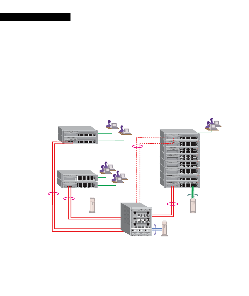
Application 1
This application sho ws Avaya P882 as the netwo rk backbone with Avaya P3 33T and
Avaya P334T stacks as closet devices with LAG and redundant links.
Figure 2.1 Avaya P333T and Avaya P334T stacks with an Avaya P882 Backbone
Avaya P333T
Avaya P334T
10/100 Mbps Ethernet
10/100 Mbps Ethernet
AvayaP880
LAG
Redundancy
Gigabit Ethernet
with LAG
10/100 Mbps
Ethernet
Avaya P333T
Avaya P334T
Avaya P334T
Avaya P334T
Avaya P334T
Avaya P334T
Avaya P333T
Avaya P334T
4x100 Mbps
LAG
Gigabit Ethernet
with LAG
Avaya P882
4x100 Mbps
LAG
Avaya P333T User’s Guide 5
Page 22
Chapter 2 Applications
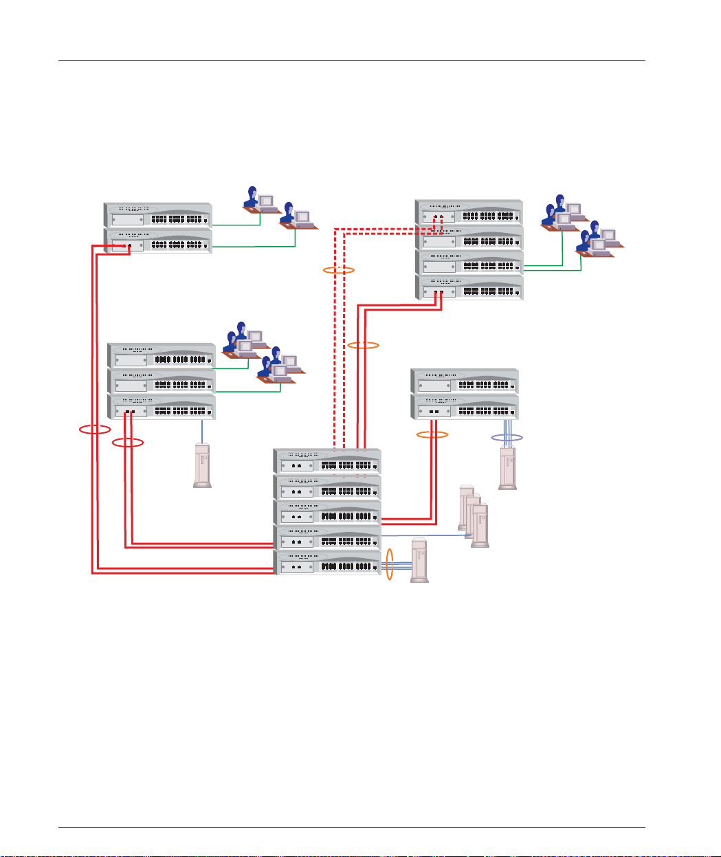
Application 2
This application shows an Avaya P330 st ack formi n g the backbo ne of a Smal l /
Medium-sized Enterprise (SME) network with Avaya P330 stacks as closet devices
with LAN and redundant links.
Figure 2.2 Avaya P330 stacks with an Avaya 330 backbone
Avaya P330
10/100 Mbps Ethernet
10/100 Mbps Ethernet
LAG
Redundancy
Gigabit Ethernet
Avaya P330
10/100 Mbps Ethernet
with LAG
4x100 Mbps
LAG
Gigabit Ethernet
with LAG
4x100 Mbps
LAG
6 Avaya P333T User’s Guide
Page 23
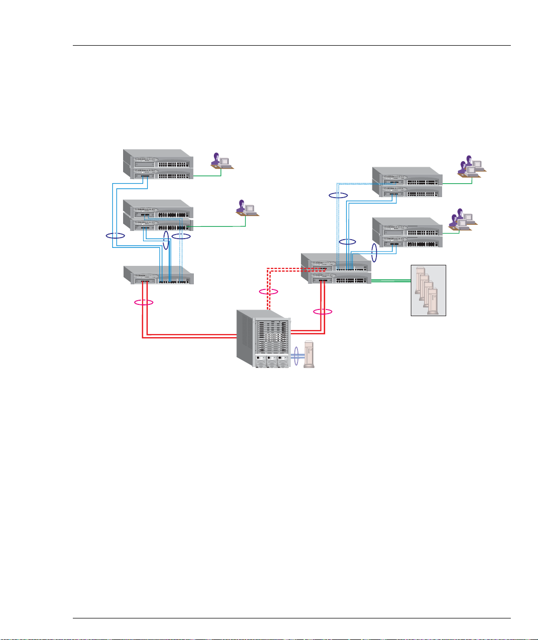
Application 3
This application shows Avaya P880 as the network backbone with Avaya P332MF
deployed as a distribution switch. An Avaya P333R multilayer switch provides local
IP routing. The Avaya P333T stacks act as closet devices with LAG and redundant
links.
Figure 2.3 Avaya P332MF with an A v aya P882 backb one
10/100 Mbps Ethernet
LAG
Redundancy
Chapter 2 Applications
10/100 Mbps Ethernet
100 Mbps
Fiber Optic
Ethernet
with LAG
Redundancy
Gigabit Ethernet
with LAG
10/100 Mbps Ethernet
LAG
Avaya P332MF
AvayaP880
Avaya P882
LAG
Redundancy
Gigabit Ethernet
4x100 Mbps
with LAG
LAG
100 Mbps
Fiber Optic
Ethernet
with LAG
Avaya P333R
Avaya P332MF
10/100 Mbps
Ethernet
Server Farm
10/100 Mbps
Ethernet
Avaya P333T User’s Guide 7
Page 24
Chapter 3
Avaya P333T Front and Back Panels
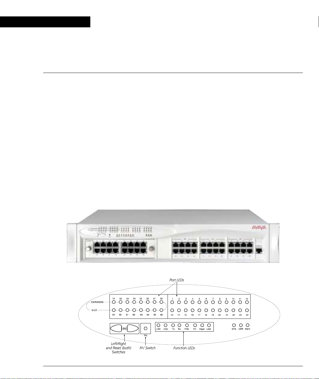
Avaya P333T Front Panel
The Avaya P333T front pan e l con t ai ns LE Ds , co nt ro ls, connectors and an expansion
Module slot, as well as a console connector. The status LEDs and control buttons
provide at-a-glance information.
The front panel LEDs consist of Port LEDs and Function LEDs. The Port LEDs
display information for each port according to the illuminated function LED. The
function is selected by pressing the left or right button until the desired parameter
LED is illuminated.
For example, if the COL LED is illuminated, then all Port LEDs sho w the collision
status of their respective port. If you wish to select the LAG function, then press the
right button until the LAG Function LED is lit; if you then wish to select Rx then
press the left button several times until the Rx function LED lights.
Figure 3.1 shows the Avaya P333T front pane l. Figure 3.2 shows a detailed view of
the LEDs (described in Table 3.1), pushbuttons, the Expansion Module slot, and the
RJ-45 console connector at the bottom right.
Figure 3.1 Avaya P333T Front Panel
Figure 3.2 Avaya P333T LEDs
Avaya P333T User’s Guide 8
Page 25

Chapter 3 Avaya P333T Front and Back Panels
Note: All LEDs are lit during a reset.
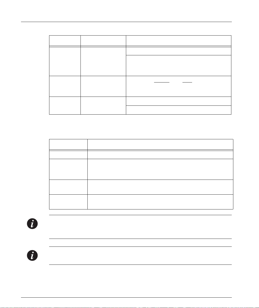
Table 3.1 Avaya P333T LED Descriptions
LED Name Description LED Status
OFF – power is off
PWR Power status
ON – power is on
Blink – using BUPS only
OFF – Module is booting
OPR CPU operation
ON – Normal operation
OFF – Module is a slave in a stack
ON – Module is the Master of the stack and
the Octaplane and Redundant cable are
SYS System Status
connected correctly.
This LED will also light in Standalone mode.
Blink – Box is the stack Master and the stack
is in redundant mode.
The following Function LEDs ap ply to ports 1 to 66
OFF – Port disabled
LNK Port status
ON – Port enabled and link OK
Blink – Port enabled and the link is d own
OFF – No collision or FDX port
COL Collision
ON – Collision occurred on line
OFF – No transmit activity
Tx Transmit to line
ON – Data transmitted on line from the
module
OFF – No receive activity
Rx Receive from line
ON – Data received from the line into the
module
OFF – Half duplex mode
FDX H alf/Full Duplex
ON – Full duplex mode
Avaya P333T User’s Guide 9
Page 26
Chapter 3 Avaya P333T Front and Back Pan els
Table 3.1 Avaya P333T LED Descriptio ns
LED Name Description LED Status
OFF – No Flow Control
FC Flow Control
ON – Symmetric/Asymmetric Flow Control
mode is enabled and port is in full duplex
mode.
Hspd High Speed 10/100
1000
OFF: 10 N/A
ON: 100 1000
LAG
Link Aggregat ion
Group (Trunking)
OFF – No LAG defined for this port
ON – Port belongs to a L AG
Table 3.2 Avaya P330 <- -> Select buttons
Description Function
Left/Right Individual – select LED function (see table above).
Reset module Press both right and left buttons together for approximately two
seconds. All LEDs on module light up until buttons are
released.
Reset stack Press both right and left buttons together for 4 seconds. All
LEDs on stack light up until buttons are released.
FIV Force Initial Version – boot from backup initial version of the
Avaya P330 software, from Bank A (see Note below).
Note: To perform “Force Initial Version” reset the module and at the same time
press the FIV reset button (use an opened paper clip or other pointed object).
Release the reset buttons first and 1 or 2 seconds later, release the FIV button.
Note: The Port LEDs of the P333T are numbered from 1-24. Expansion Module ports
are numbered from 51. Port LED numbers 49-50 are reserved.
10 Avaya P333T User’s Guide
Page 27
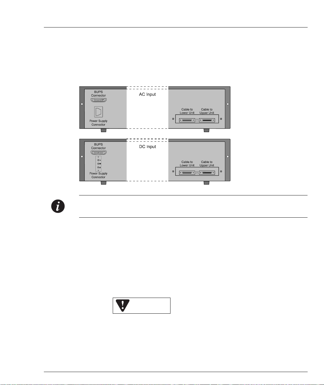
Avaya P330 Back Panel
The Avaya P330 back panel contains a stacking sub-mod ule slot, power supply and
BUPS connector. Figure 3.3 shows the back panel of the AC switch (top) and the DC
switch (bottom) with a stacking sub-module installed.
Figure 3.3 Avaya P330 AC and DC Back Panels
Chapter 3 Avaya P333T Front and Back Panels
Note: Further illustrations of the Avaya P330 Back Panel will be that of the AC
model, the topmost panel in Figure 3 . 3.
Figure 3.3 shows the back panel of the AC switch (top) and the DC switch (bottom)
with a stacking sub-module installed.
BUPS Input Connector
The BUPS input connector (see Figure 3.4) is a 5 VDC connector for use with the
Avaya P330 BUPS unit only. A BUPS Input sticker appears directly to the right the
BUPS input connector.
Figure 3.4 BUPS Input Connector Sticker
BUPS Input
Avaya P333T User’s Guide 11
Page 28

Chapter 3 Avaya P333T Front and Back Pan els
12 Avaya P333T User’s Guide
Page 29

Chapter 3 Avaya P333T Front and Back Panels
Avaya P333T User’s Guide 13
Page 30

Chapter 3 Avaya P333T Front and Back Pan els
14 Avaya P333T User’s Guide
Page 31

Chapter 3 Avaya P333T Front and Back Panels
Avaya P333T User’s Guide 15
Page 32

Chapter 3 Avaya P333T Front and Back Pan els
16 Avaya P333T User’s Guide
Page 33

Chapter 3 Avaya P333T Front and Back Panels
Avaya P333T User’s Guide 17
Page 34

Chapter 3 Avaya P333T Front and Back Pan els
18 Avaya P333T User’s Guide
Page 35

Chapter 4
Installation and Setup
The Avaya P333T is ready to work after you carry out the installati on instructions
given below. All the Avaya P333T ports provide complete connectivity and no
configuration is required to make the system work.
Installing the X330STK Stacking Sub-module in the P330
Caution: The stacking sub-modules contain component s sensitive to electrostatic
discharge. Do not touch the circuit board unless instructed to do so.
To install the stacking sub-module i n the A vaya P330:
1 Remove the blanking plate from the back of the Avaya P330 switch.
2 Insert the stacking sub-module gently into the slot, ensuring that the metal base
plate is aligned with the guide rails.
The metal plate of the X330STK (and not the PCB) fits onto the guide rails.
3 Press the sub-module in firmly until it is completely inserted into the
Avaya P330.
4 Gently tighten the two screws on the side panel of the stacking sub-module by
turning them.
Note: The Avaya P330 switch must not be operated with the back-slot open; th e
stacking sub-module should be covered with the supplied blanking plate if necessary.
Positioning
Avaya P330 can be mounted alone or in a stack in a standard 19-in ch equipment
rack in a wiring closet or equipment room. Up to 10 units can be stacked in this way.
When deciding where to position the unit, ensure that:
• It is accessible and cables can be connected easily and according to the
configuration rule.
• Cabling is away from sources of electrical noise such as radio transmitters,
broadcast amplifiers, power lines an d fl uorescent lighting fixtures.
• Water or moisture cannot enter the case of the unit.
• There is a free flow of air around the unit and that the vents in the back and
sides of the case are not block ed.
Avaya P333T User’s Guide 19
Page 36

Chapter 4 Installation and Setup
Note: Use Octaplane cables to interconnect with other sw itches.
Rack Mounting
The Avaya P330 case fits in most standard 19-inch racks. Avaya P330 is 2U (88mm,
3.5”) high.
Place the Avaya P330 in the rack as follows:
1 Snap open the hinged ends of the front panel to reveal the fixing holes.
2 Insert the unit into the rack. Ensure that the four Avaya P330 screw holes are
aligned with the rack hole positions as shown in Figure 4.1.
Figure 4.1 Avaya P330 Rack Mounting
3 Secure the unit in the rack using the screws. Use two screws on each side. Do
not overtighten the screws.
4 Snap closed the hinged ends of the front panel.
5 Ensure that ventilation holes are not obstructed.
20 Avaya P333T User’s Guide
Page 37

Connecting Stacked Switches
Note: The two ends of the Octaplane cable terminate with different connectors. Each
connector can only be connected to its matching port.
The following cables are used to connect stacked switches:
• Short Octaplane cable (X330SC) – ivory-colored, used to connect adjacent
switches (Catalog No. CB0223) or switches separated by a BUPS unit.
• Long/Extra Long Octaplane cable (X330LC/X 330L-LC) – ivory-col ored, used to
connect switches from two different physical stacks, or switches separated by a
BUPS unit (Catalog No. CB0225/CB0270).
• Redundant/Long Redundant Octaplane cable (X330RC/X330L-RC) – black,
used to connect the top and bottom switches of a stack (Catalog No. CB0222/
CB0269).
These are the same cables that are used with all P330 family modules.
To connect stacked switches:
Chapter 4 Installation and Setup
Note: When adding a module to an existing stack, first connect the stacking cables
and then power up the module.
1 Plug the light grey connector of the Short Octaplane cable into the port marked
“to upper unit” of the bottom Avaya P330 switch.
2 Plug dark grey connector of same Short Octaplane cable to the port marked “to
lower unit” in the unit above. The connections are ill ustrated in Figure 4.3.
3 Repeat Steps 1 and 2 until you reach the top switch in the stack.
4 If you wish to implement stack redundancy, use the Redundant Cable to
connect the port marked “to lower unit” on the bottom switch to the port
marked “to upper unit” on the top switch of the stack.
5 Power up the added modules.
Caution: Do not cross-connect two Avaya P330 switches with two Octaplan e (li ghtcolored) cables. If you wish to cross-connect for redundancy, use one light-colored
Octaplane ca ble and one black redundancy cable. Figure 4.2 shows an incorrect
connection.
Avaya P333T User’s Guide 21
Page 38

Chapter 4 Installation and Setup
Note: You can build a stack of up to 10 Avaya P330 switches. If you do not wish to
stack all the switches in a single rack, use long Octaplane cables to connect two
physical stacks as shown in Figure 4.3.
Figure 4.2 Incorrect Stack Connection
BUPS
Connector
Power Supply
Connector
BUPS
Connector
Power Supply
Connector
Cable to
Lower Unit
Cable to
Lower Unit
Cable to
Upper Unit
Cable to
Upper Unit
22 Avaya P333T User’s Guide
Page 39

Figure 4.3 Avaya P330 Stack Connections
0
Chapter 4 Installation and Setup
Connector
Power Supply
Connector
Connector
Power Supply
Connector
Connector
Power Supply
Connector
Connector
Power Supply
Connector
Connector
Power Supply
Connector
BUPS
BUPS
BUPS
BUPS
BUPS
X330RC
Cable to
Cable to
Upper Unit
Lower Unit
X330SC
Cable to
Cable to
Upper Unit
Lower Unit
Cable to
Cable to
Upper Unit
Lower Unit
Cable to
Cable to
Upper Unit
Lower Unit
Cable to
Cable to
Upper Unit
Lower Unit
BUPS
Connector
5
Power Supply
Connector
BUPS
Connector
4
Power Supply
Connector
BUPS
Connector
3
Power Supply
Connector
BUPS
Connector
2
Power Supply
Connector
BUPS
Connector
1
Power Supply
Connector
Cable to
Cable to
1
Upper Unit
Lower Unit
Cable to
Cable to
Lower Unit
Lower Unit
Lower Unit
Lower Unit
9
Upper Unit
8
Cable to
Cable to
Upper Unit
Cable to
Cable to
7
Upper Unit
6
Cable to
Cable to
Upper Unit
X330LC
Avaya P333T User’s Guide 23
Page 40

Chapter 4 Installation and Setup
Installing Expansion Sub-modules
Caution: The expansion sub-modules contain components sensitive to electrostatic
discharge. Do not touch the circuit board unless instructed to do so.
Installing the Expansion Sub-module into the Avaya P330
1 Remove the blanking plate or other sub-module (if installed).
2 Insert the sub-module gently into the slot, ensuring that the Printed Circuit
Board (PCB) is aligned with the guide rail s.
The PCB not the metal base plate fits into the guide rail.
3 Firmly press the sub-module until it is completely inserted into the Avaya P330.
4 Gently tighten the two screws on the front panel of the expansion sub-module
by turning them.
Removing an Existing Expansion Sub-module
1 Loosen the screws by turning the knobs.
2 Take hold of the two knobs (one near each side of the front panel) and pull
gently but firmly towards yourself.
3 Insert another expansion sub-module or the blanking plate.
Note: If an expansion sub-module is removed from the stack with the power supply
on, all configuration definitions on expansion sub-modules are lost. To remove an
expansion sub-module and save configuration definitions:
1 Turn off the power supply.
2 Remove an expansion sub-module.
3 Insert another expansion sub-module.
4 Turn on the power supply.
Note: The Avaya P330 switch must not be operated with the expansion slot open;
the expansion sub-module slot should be covered with the supplied blanking plate
if necessary.
24 Avaya P333T User’s Guide
Page 41

Powering On – Avaya P330 Module AC
For the AC input version of the Avaya P330, insert the AC power cord into the
power inlet in the back of the unit. The unit powers up even if no direct AC power is
applied to it.
1 If you are using a BUPS, insert a power cord from the BUPS into the BUPS
connector in the back of the unit. The unit powers up.
2 After power up or reset, the Avaya P330 performs a self test procedure.
Powering On – Avaya P330 Module DC
For the DC input version of the Avaya P330, connect the power cable to the swit ch
at the input terminal block.
1 The terminals are marked “+”, “-“ and with the IEC 5019a Ground symbol.
2 The size of the three screws in the terminal block is M3.5.
3 The pitch between each screw is 9.5mm.
Warning: Before performing any of the following procedures, ensure that DC power
is OFF.
Chapter 4 Installation and Setup
Caution: This product is intended f or installation in restricted access areas and is
approved for use with 18 AWG copper conductors only. The installation must
comply with all applicable codes.
4 Connect the power cable to the DC power supply.
Warning: The proper wiring sequence is ground to ground, positive to positive and
negative to negative. Always connect the ground wire first and disconnect it last.
Avaya P333T User’s Guide 25
Page 42

Chapter 4 Installation and Setup
Configuring the Switch
The Avaya P330 may be configured using the text-based Command Line Interface
(CLI), the built-in Avaya P330 Device Manager (Embedded Web) or Avaya MultiService Network Manager™.
For instructions on the text-based utility, see the CLI chapter.
For instructions on installa tion of the graphical user interfaces, see the Avaya P330
Device Manager Appendix. For instructions on the use of the graphical user
interfaces, refer to the Device Manager User’s Guide on the Documentation and
Utilities CD.
Avaya P330 Default Settings
The default settings for the Avaya P330 switch and its ports are determined by the
Avaya P330 software. Thes e defau lt settin gs are s ubject to ch ange in newe r versio ns
of the Avaya P330 software. See the Release Notes for the most up-to-date settings.
Table 4.1 Default Switch Settings
Function Default Setting
IP address 149.49.32.134
Default gateway 0.0.0.0
VLANs VLAN 1
Spanning tree Enabled
Bridge priority for Spanning Tree 32768
Time server IP address 0.0.0.0
Timezone offset 0 hours
Read-only SNMP community string Public
Read-write SNMP community string P ublic
Trap SNMP community string Public
SNMP retries number 3
SNMP timeout 2000 Seconds
SNMP authentication trap Disabled
CLI timeout 15 Minutes
User Name/Password root/root
26 Avaya P333T User’s Guide
Page 43

Chapter 4 Installation and Setup
Table 4.2 Default Port Settings
Function Default Setting
10/100Base-TX ports 100Base-F ports 1000 Base-X ports
Duplex mode Full duplex Full duplex Full duplex only
Port Speed 100M 100M 1000M
Flow control Off Off Off
Flow control
Off N/A Off (No pause)
advertisement
Backpressure On (only in Half duplex) Not Applicable Not Applicable
Autopartitioning Dis able d (onl y in Ha lf
N/A N/A
duplex)
Auto-negotiation Enab le Not Applicable Enable
1
Administration status Enable Enable Enable
Port VLAN 1 1 1
Tagging mode Clear Clear Clear
Port priority 0 0 0
Spanning Tree cost 20 20 4
Spanning Tree port
128 128 128
priority
1 Ensure that the other side is also set to Autonegotiation Enabled
Note: Functions operate in their default settings unless configured otherwise.
Avaya P333T User’s Guide 27
Page 44

Chapter 4 Installation and Setup
Cabling
Avaya P330 modules include the following types of ports (according to the speed
and standard they support): 10Base-T, 100Base-TX, 100Base-FX, 1000Base-SX and
1000Base-LX.
Note: To interconnect Avaya P330 switches with twisted pairs, crossed cables are
required.
• The maximum UTP cable length connected to a 10/100 Mbps port operating as
10Base-T, is 100 m (328 ft.).
• A UTP Category 5 cable must be conn ected t o any 100Base-TX port, via an RJ45
connector. The maximum UTP cable length connected to a 10/100 Mbps port
operating as 100Base-TX, is 100 m (328 ft.).
• A fiberoptic cable must be connected to any 100Base-FX port, via a pair of SC
connectors. The maximum fiber cable length connected to a 100Base-FX port is
412 m (1,352 ft) when operating in half duplex, and 2 km (6,562 ft) when
operating in full duplex.
Appropriate cables are available from your local supplier.
Table 4.3 Gigabit Ethernet Cabling
Gigabit
Interface
Fiber
Type
Diameter
(µm)
Modal
Bandwidth
(MhzKm)
Maximum
Distance
(m)
Minimum
Distance
(m)
Wavelength
(nm)
1000BASE-SX MM 62.5 160 220 2 850
1000BASE-SX MM 62.5 200 275 2 850
1000BASE-SX MM 50 400 500 2 850
1000BASE-SX MM 50 500 550 2 850
1000BASE-LX MM 62.5 500 550 2 1310
1000BASE-LX MM 50 400 550 2 1310
1000BASE-LX SM 9 NA 10,000 2 1310
28 Avaya P333T User’s Guide
Page 45

Connecting th e Console Cable
The Avaya P330 has one seri a l port o n th e fro nt pa nel o f t he sw itc h fo r co nn ecti ng a
terminal, a terminal emulator, or a modem.
The serial port on the front panel is labelled “Console” and has a RJ-45 co nnector.
Connect the P330 to a terminal or a terminal emulator using the supplied console
cable and the RJ-45 to DB-9 adaptor. To connect a modem, use the supplied cable
and an RJ-45 to DB-25 adaptor.
Note: The cable and two adaptors can be found in the accessory set, and they are
clearly marked.
Configuring the Terminal Serial Port Parameters
The serial port settings for using a terminal or terminal emulator are as follows:
• Baud Rate - 9600 bps
• Data Bits - 8 bits
• Parity - None
• Stop Bit - 1
• Flow Control - None
• Terminal Emulation - VT-100
Chapter 4 Installation and Setup
Connecting a Modem to the Console Port
A PPP connection with a modem can be established only after the
Avaya P330 is configured with an IP address an d net-mask, and the PPP param eters
used in the Avaya P330 are compatible with the modem’s PPP parameters.
1 Connect a te rm inal t o th e con s ole port o f the Avay a P 330 s wit ch a s descri bed i n
Connecting the Console Cable on page 29.
2 When you are prompted for a Login Name, enter the default name root.
3 When you are prompted for a password, enter the password root. You are
now in Supervisor Level.
4 At the prompt, type:
set interface ppp <ip_addr><net-mask>
with an IP address and netm as k to be used by t h e Avaya P 33 0 t o conn ect vi a it s
PPP interface.
Note: The PPP interface configured with the set interface ppp command
must be on a different subnet from the stack inband interface.
Avaya P333T User’s Guide 29
Page 46

Chapter 4 Installation and Setup
5 Set the baud rate, ppp authentication, and ppp time out required to match your
modem. These commands are described in the “Command Line Interface”
chapter.
6 At the prompt, type:
set interface ppp enable
The CLI responds with the following:
Entering the Modem mode within 60 seconds...
Please check that the proprietary modem cable is plugged
into the console port
7 Use the DB-25 to RJ-45 connector to plug the console cable to the modem’s DB-
25 connector. Plug the other end of the cable RJ-45 connector to the
Avaya P330 console’s RJ-45 port.
8 The Avaya P330 enters modem mode.
9 You can now dial into the switch from a remote station, and open a Telnet
session to the PPP interface IP address.
Assigning P330’s IP Stack Address
Note: All P330 switches are shipped with the same default IP address. You must
change the IP address of the master P330 switch in a stack in order to guarantee that
the stack has its own unique IP address in the network.
Use the CLI to assign the P330 stack an IP address and net mask. The network
management station can estab lish communications with the stack once this address
had been assigned and the stack has been inserted into the network.
To assign a P330 IP stack address:
1 Est ablis h a seri al conne ctio n by connecti ng a te rminal to th e Master P3 30 sw itch
of the stack.
2 When prompted for a Login Name, enter the default name root
3 When you are prompted for a password, enter the password root. You are
now in Supervisor Level.
4 At the prompt, type:
set interface inband <vlan> <ip_address> <netmask>
Replace <vlan>, <ip_address> and <netmask> with the VLAN,
IP address and net mask of the stack.
5 Press Enter to save the IP address and net mask .
6 At the prompt, type reset and press Enter to reset the stack. After the Reset,
log in again as described above.
7 At the prompt, type set ip route <dest> <gateway> and replace <dest>
and <gateway> with the destination and gateway IP addresses.
8 Press Enter to save the destination and gateway IP addresses.
30 Avaya P333T User’s Guide
Page 47

Chapter 5
Avaya CLI – Architecture, Access & Conventions
This chapter describes the Avaya P330 CLI architecture and conventions, and
provides instructions for accessing the Avaya P330 for configuration purposes.
The configuration procedure involves establishing a Telnet session or a serial
connection and then using t he Av ay a P3 30’ s i nte rn al CL I. The CLI is com ma nd-li n e
driven and does not have any menus. To activate a configuration option, you must
type the desired command at the prompt and press Enter. You can also configure
your Avaya P330 using the P330 Manager with its graphical user interface. For
details, see the Avaya P330 De vice Manager Appendix and the Avaya Multi-Service
Network Manager P330 Device Manager User’s Guide on the Documentation and
Utilities CD.
Establishing a Serial Connection
Perform the following steps to connect a terminal to the Avaya P330 Master Switch
Console port for configuration of Stack or Router parameters:
1 Use the serial cable supplied to attach the RJ-45 console connector to the
Console port of the Avaya P330 Master Switch. Connect the DB-9 connector to
the serial (COM) port on your PC/terminal.
2 Ensure that the serial port settings on the terminal are 9600 baud, 8 bits, 1 stop
bit and no parity.
3 When you are prompted for a Login Name, enter the default login. The default
login is root.
4 When you are promoted for a password, enter the user level password root.
5 Now you can begin the configuration of Module or Stack parameters.
Avaya P333T User’s Guide 31
Page 48

Chapter 5 Avaya CLI – Architecture, Access & Conventions
Establishing a Telnet Connection
Perform the following steps to establish a Telnet connection to the Avaya P330 for
configuration of Stack or Router parameters. You can Telnet either the Stack Master
IP address or directly to one of the Router IP address:
1 Connect your station to the network.
2 Verify that you can communicate with the Avaya P330 using Ping to the IP of
the Avaya P330. If there is no response using Ping, check the IP address and
default gateway of both the Avaya P330 and the station.
Note: The Avaya P330 default IP address is 149.49.32.134 and the default subnet
mask is 255.255.255.0.
3 From the Microsoft Windows
from the DOS prompt of your PC), then start the Telnet session by typing:
telnet
For example: telnet 149.49.32.134
4 If the IP Address in Telnet command is the IP address of the stack, then
connection is established with the Switch CLI entity of the Master module.
If you want to connect to the Router CLI entity, use the session command.
If the IP address in the Telnet command is of the router, connection is
established to the Router CLI entity in the router module.
5 When you see the “Welcome to P330” menu and are prompted for a Login
Name, enter the default name root
6 When you are prompted for a password, enter the User Level pass word root
or norm in lower case letters (do NOT use uppercase letters). The User level
prompt will appear when you have established communications with the
Avaya P330. Enter the P330 Privileged level by typing enable
7 You can now configure the Avaya P330 stack and change its default IP address.
<P330_IP_address>
®
taskbar of your PC click Start and then Run (or
32 Avaya P333T User’s Guide
Page 49

Command Line Prompt
When you start the CLI, the initial prompt shows the number of the Master module
in the Avaya P330 stack. For example, if the stack Mast er is Modu le 5, cou nting from
the bottom up, then the prompt is:
P330-5>
In this document the Module number in the prompt is generic and is represented by
“N”.
If you wish to open a session with an Avaya P333R-LB routing module in the stack
or reopen a session with the Master module, use the session command (see
below).
The command prompt is not hierarchical in structure. If you wish to use several
commands, each beginning with the same keyword, you must retype all parts of
the command each time. For example, if after you want to set the system contact
and the system name you must type both set system contact and set
system name. However, you can use command abbreviations.
Avaya P330 Sessions
You can use sessions to switch between P330 modules or to switch between Layer 2
and Layer 3 commands in the P333R CLI.
To switch between P330 modules use the command:
session [<mod_num>] <mode>.
The <mod_num> is the number of the module in the stack, counting from the bottom
up. The <mode> can be either switch or router. When Module Number is not
specified, the command switches between the modes in the local module. Use
switch mode to configure l a yer 2 commands. Use router mode to configure routing
commands.
Examples:
To configure router parameters in the module that you are currently logged into,
type the following command:
session router.
Chapter 5 Avaya CLI – Archite c tu re , Ac ce ss & Conventions
To configure the switch parameters, on module 6, type the command:
session 6 switch.
Note: When you use the session command the security level stays the same.
Avaya P333T User’s Guide 33
Page 50

Chapter 5 Avaya CLI – Architecture, Access & Conventions
Security Levels
There are four security access levels – User, Privileged, Configure and Supervisor.
• The User level is a general access level used to show system parameter values.
• The Privileged level is used by site personnel to access stack configuration
options.
• The Configure level is used by site personnel for Layer 3 configuration.
• The Supervisor level is used to define user names, passwords, and access levels
of up to 10 local users.
A login name and password are always required to access the CLI and the
commands. The login names and passwords , an d s ecu rity levels are established
using the username command.
Switching between the entities, does not effect the security level since security levels
are established specifically for each user. For example, if the operator with a
privileged security level in the Switch entity switches to the Router entity the
privileged security level is retained.
Entering the Supervisor Level
The Supervisor level is the level in which you first enter Cajun Campus CLI and
establish user names for up to 10 local users. When you enter the Supervisor level,
you are asked for a Login name. Type root as the Login name and the default
password root (in lowercase letters):
Welcome to P330
Login: root
Password:****
Password accepted.
P330-N(super)#
Defining new users
Define new users and access levels using the username command in Supervisor
Level. (see page 135).
Exiting the Supervisor Level
To exit the Supervisor level, type the command exit.
34 Avaya P333T User’s Guide
Page 51

Entering the CLI
To enter the CLI, enter your username and password. Your access level is indicated
in the prompt as follows:
The User level prompt is shown below:
P330-N>
The Privileged level prompt is shown below:
P330-N#
The Configure level prompt for Layer 3 configu ration is shown below:
P330-N(configure)#
The Supervisor level prompt is shown below:
P330-N(super)#
Entering the Technician Level
This level is can only be accessed from the Privileged and Supervisor levels not from
the User level.
This feature is not documented and is for use by Avaya Technical S upport only.
Conventions Used
Chapter 5 Avaya CLI – Archite c tu re , Ac ce ss & Conventions
The following conventions are used in this chapter to convey instructions and
information:
• Mandatory keywords are in boldface.
• Variables that you supply are in pointed brack et s <>.
• Optional keywords are in square brackets [].
• Alternative but mandatory keywords are grouped in braces {} and separated by
a vertical bar |.
• If you enter an alphanumeric string of two words or more, enclose the string in
inverted commas.
• Information displayed on screen is displayed in text font.
Avaya P333T User’s Guide 35
Page 52

Chapter 5 Avaya CLI – Architecture, Access & Conventions
Navigation, Cursor Movement and Shortcuts
The CLI contains a simple text editor with these functions:
Table 5.1 Navigation, Cursor Movement and Shortcuts
Keyboard Functions
Backspace Deletes the previous character
Up arrow/Down arrow Scrolls back and forward through the command
history buffer
Left arrow/Right arrow Moves the cursor left or right
Tab Completes the abbreviated command. Type the
minimum number of ch aracters unique to the
command. An exception is the Reset System
command which you must type in full.
Enter Executes a single-line command
“ “ If you type a name with quotation marks, the
marks are ignored.
Getting Help
On-line help may be obtained at any time by typing a question mark (?), or the
word help on the command line or by pressing th e F1 key. To obtain help for a
specific command, type the command followed by a space and a question mark.
Example: Router> show?
Command Syntax
Commands are not case-sensitive. That is, uppercase and lowercase characters may
be interchanged freely.
Command Abbreviations
All commands and parameters in the CLI can be truncated to an abbreviation of any
length, as long as the abbreviation is n ot ambiguous. For exampl e, version can
be abbreviated ver.
For ambiguous commands, type the beginning letters on the command line and
then use the Tab key to toggle through all the possible command s beginning with
these letters.
36 Avaya P333T User’s Guide
Page 53

Universal Commands
Universal commands are command s that can be issued any where in the h ierarchical
tree.
Top and Up commands
The Up command moves you up to the next highest level in the CLI comman d
hierarchy. The Top command moves you to the highest level.
Retstatus command
Use the retstatus command to show whether the last CLI command you
performed was successful. It displays the return status of the previous command.
The syntax for this command is: retstatus
Output Example:
P330 # set port negotiation 2/4 disable
Link negotiation protocol disabled on port 2/4.
Tree command
The tree command displays the commands that are available at your curre nt
location in the CLI hierarchy.
The syntax for this command is: tree
Chapter 5 Avaya CLI – Archite c tu re , Ac ce ss & Conventions
Avaya P333T User’s Guide 37
Page 54

Chapter 5 Avaya CLI – Architecture, Access & Conventions
38 Avaya P333T User’s Guide
Page 55

Chapter 6
CLI – Layer 2
This chapter provides all the Layer 2 CLI commands, parameters and their default
values.
The CLI is command-line driven and does no t have any menus. To activate a
configuration option, you must type the desired command at the prompt and press
Enter.
Note: The terms “module” and “switch” are used interchangeably.
User Level Commands
This section describes all commands that are available from the User level.
Following is a table of the User Level commands and command groups (all
commands are also available at the higher levels).
• session Opens a session to another P330 switch, X330
ATM Access sub-module, X330 WAN Access
sub-module or G700 MGP.
• terminal width Displays or sets the width of the terminal
display.
• terminal length Display or set the length of the terminal
display.
• clear screen Clears the current terminal display. Page 41
• show
• ping Sends ICMP echo request packets to another
• dir Show files in the system. Page 79
Avaya P333T User’s Guide 39
1
1 This command corresponds to a group of commands and is shown in a
separate Table on Page 42.
Shows the current switch parameters. Page 42
node on the network.
Page 40
Page 40
Page 40
Page 41
Page 56

Chapter 6 CLI – Layer 2
session
Use the session command to open a session with a specific entity in a switch of
the stack. For example, you can open a session with the Routing entity of a
P332G-ML switch in the stack, or with an the X330 ATM sub-module entity plugged
into a specific switch.
The syntax for this command is:
session [<mod_num> [switch|router|atm|mgp|wan]]
mod_num (optional) The switch number.
switch|router|atm|mgp|wan (optional) The entity to w hich you want to
If you do not specify this parameter, you will
get the default entity of the stack (Layer 2
session to the Master)
open a session.
If you do not specify this parameter, you will
get the default entity of the specific module:
switch - Layer 2 entity of the switch (see
Note below).
router - Routing entity.
atm - ATM entity.
mgp - Media Gateway Precessor.
wan - WAN access router entity.
Note: Layer 2 commands are only available if you open a switch session with the
Master switch.
Note: When you use the session command the security level stays the same.
terminal
Use the terminal width and terminal length commands to set the width
and length of the terminal display in characters.
The syntax for this command is:
terminal {width|length} [<characters>]
40 Avaya P333T User’s Guide
Page 57

clear screen
ping
Chapter 6 CLI – Layer 2
The clear screen command clears the current terminal display.
The syntax for this command is:
clear screen
Use the ping command to send ICMP echo request packets to another node on the
network.
The syntax for this command is:
ping [host[number]]
host Host IP address/Internet address of route destination. If missing
then the last host IP is used.
number Number of packets to send. If missing, then the last number is used.
If the last number is not available, the default is 4.
Note: You can use this command via the Master switch only.
Output Example:
To ping the IP number 149.49.48.1 four times:
P330-N> ping 149.49.48.1 4
PING 149.49.48.1: 56 data bytes
64 bytes from 149.49.48.1: icmp_seq=0. time=0. ms
64 bytes from 149.49.48.1: icmp_seq=1. time=0. ms
64 bytes from 149.49.48.1: icmp_seq=2. time=0. ms
P330-1(super)# 64 bytes from 149.49.48.1: icmp_seq=3. time=0. ms
----149.49.48.1 PING Statistics---4 packets transmitted, 4 packets received, 0% packet loss
round-trip (ms) min/avg/max = 0/0/0
Avaya P333T User’s Guide 41
Page 58

Chapter 6 CLI – Layer 2
Show Commands Summary Table
Following is a table of the show commands:
• show time Shows the current time. Page 45
• show timezone Shows the current timezone offset. Page 45
•show time
Shows the status and parameters. Page 45
parameters
• show ip route Shows the IP routing table entries. Page 46
• show image version Shows the image version. Page 46
• show download
Shows the last download operation. Page 47
status
• show snmp Shows the SNMP community strings. Page 47
• show snmp retries S hows the SNMP retries number. Page 48
• show snmp timeout Sh ows the SNMP timeout. Page 48
• show timeout Shows the CLI logout time setting. Page 48
• show logout Shows the CLI logout time set ting. Page 48
• show interface Shows the interfaces of the device. Page 49
• show device-mode Shows the operating mode you are
Page 49
currently in.
• show port Shows settings and status for all ports. Page 50
• show port t rap Sh ows the port trap. Page 51
• show port channel Shows the port channel. Page 51
•show port
Displays the port classification. Page 52
classification
•show port
redundancy
•show intermodule
port redundancy
Displays information on redundancy
schemes.
Shows the stack’s intermodule
redundancy.
Page 52
Page 53
• show port mirror Shows mirroring information. Page 53
•show port vlan-
Shows port vlan binding mode settings. Page 53
binding-mode
• show port security Lists th e se curity mode of the ports of a
Page 54
switch or stack.
• show port blocking Displays the port blocking mode on a
Page 54
particular switch.
42 Avaya P333T User’s Guide
Page 59

Chapter 6 CLI – Layer 2
•show port self-loopdiscovery
Displays which port or switch has an
enabled IBM™ token r ing cable loop
Page 57
discovery status.
•show internal
buffering
• show boot bank Displays the software bank f r om which
Shows the current internal buffering
capacity.
Page 57
Page 58
the switch will load.
• show module Shows switch status and information. Page 58
•show port
flowcontrol
• show cam Shows the CAM table entries for a
Shows the per-port status information
related to flow control.
Page 60
Page 62
specific port.
• show cascading fault-
Shows cascading fault monitoring mode. Page 62
monitoring
•show port autonegotiationflowcontrol-
Displays the flowcontrol advertisement
for a Gigabit port when performing
autonegotiation.
Page 63
advertisement
• show trunk Displays VLAN tagging inf ormation of
Page 63
the ports, port binding mode, and the
port VLAN ID.
• show vlan Displays the VLANs configured in the
Page 64
stack/switch.
• show leaky-vlan Displays the leaky VLAN status. Page 65
• show spantree Shows Spanning Tree Prot ocol (STP)
Page 65
settings.
• show autopartition Show s the autopartition settings. Page 67
• show dev log file Displays the encrypted device log file. Page 67
• show log Displays an encrypted device reset log. Page 67
•show module-
Displays the switch’s identity. Page 68
identity
• show license Shows the license. Page 68
• show system Shows system para meters. Page 69
• show rmon statistics Shows the traffic statistics of an interface. Page 70
• show rmon history Shows the existing history entries. Page 71
• show rmon alarm Shows the exist i ng alarm entr ies. Page 71
Avaya P333T User’s Guide 43
Page 60

Chapter 6 CLI – Layer 2
• show rmon event Shows the existing event entries. Page 72
• show ppp session Shows the PPP parameters of the active
Page 72
PPP session.
• show ppp
authentication
• show ppp incoming
timeout
Shows the authentication method used
for PPP sessions.
Shows the amount of time PPP sessions
can remain idle before being
Page 72
Page 73
disconnected.
• show ppp baud-rate Shows the baud rate. Page 73
• show ppp
Displays the ppp configuration. Page 73
configuration
• show tftp upload/
download status
• show tftp download
software status
Shows the status of the TFTP upload/
download configuration per switch.
Shows the status of the TFTP software
download of the Device Manager
Page 74
Page 74
software to the switch.
•show web
aux-files-url
• show intelligentmulticast
• show intelligentmulticast hardware
Shows the locati on (URL/director y) of
the P330 Device Manager Help files.
Shows the status IP multicast filtering
application.
Shows whether the connected unit’s
hardware supports IP multicast filtering.
Page 75
Page 75
Page 76
support
• show security mode Displays the status of the MA C security
Page 76
feature (enabled/disabled).
• show secure mac port Shows the secure MAC addresses of a
Page 77
port.
• show arp-tx-interval Displays the keep-alive status. Page 77
•show arp-aginginterval
• show self-loop
Displays the ARP table aging interval for
Page 77
gateways’ entries.
Displays the self-loop discovery mode. Page 78
discovery
• show allowed
managers status
• show allowed
managers table
44 Avaya P333T User’s Guide
Displays the status of the a llowed
managers feature (enabled/disabled) .
Displays the IP add r esses of the allowed
managers.
Page 78
Page 79
Page 61

Chapter 6 CLI – Layer 2
show time
show timezone
• dir Displays the file types that have been
Page 79
downloaded to the module.
Use the show time command to display the current stack time.
The syntax for this command is:
show time
Output Example:
P330-N> show time
10:32:34 27 JAN 2000 GMT
Use the show timezone command to display the current stack timezone.
The syntax for this command is:
show timezone
Output Example:
P330-N> show timezone
Timezone set to 'GMT', offset from UTC is 0 hours
show time parameters
Use the show time parameters command to display the status and
parameters.
The syntax for this command is:
show time parameters
Output Example:
P330-N> show time parameters
Current time: L:02:49:11 02 JAN 1999 isl
Timezone set to ’isl’, offset from UTC is 2 hours
Time-Server: 0.0.0.0
Time acquired from Time-Server: 0.0.0.0
Time protocol set to: TIME protocol
Avaya P333T User’s Guide 45
Page 62

Chapter 6 CLI – Layer 2
show ip route
Use the show ip route com ma nd to display IP routing table entries.
The syntax for this command is:
show ip route
Output Example:
P330-N> show ip route
Destination Gateway
----------- -----------
149.49.1.1 172.20.22.201
190.20.0.0 172.20.22.202
172.20.0.0 172.20.22.96
show image version
Use the show image version command to display the software version of the
image on both memory banks of a specified switch.
The syntax for this command is:
show image version [<mod_num>]
If no switch number is specified, the image version of the all sw itches will be
displayed.
Output Example:
P330-N> show image version 1
Mod Module-Type Bank Version
------ ----------- ---- -------1 24x10/100Base-T with optional expansion slot A 3.3.14
1 24x10/100Base-T with optional expansion slot B 3.5.19
46 Avaya P333T User’s Guide
Page 63

show download status
Use the show download status command to disp lay a summary of the last
software download operation.
The syntax for this command is:
show download status [slot]
Output Example:
P330-1(super)# sh download status 1
Mod Bank Download State Activity Status Download Size
----- ------ --------------- ---------------- ---------------
1. Bank B idle Download idle 0
Mod Version Host File
----- --------- ------------- ------------------
1. 3.5.18 149.49.70.61 d:\p340sw\gt-ml\3.5.18\p332gt_ml
Note: This command is only suppor ted by the P3 32G-ML and P3 32GT-ML s witche s.
Chapter 6 CLI – Layer 2
show snmp
Use the show snmp command to display SNMP information.
The syntax for this command is:
show snmp
Output Example:
P330-N> show snmp
Authentication trap disabled
Community-Access Community-String
---------------- ---------------read-only public
read-write public
trap public
Trap-Rec-Address Traps Enabled
---------------- ----------------
1.1.1.1 config
fault
etc...
Avaya P333T User’s Guide 47
Page 64

Chapter 6 CLI – Layer 2
show snmp retries
Use the show snmp retries command to display the number of retries initiated
by the Device Manager application when it tries to send SNMP messages to the
device.
The syntax for this command is:
show snmp retries
Output Example:
P330-N> show snmp retries
the SNMP Retries Number is 3
show snmp timeout
Use the show snmp timeout command to display the default SNMP timeout in
seconds. This command is useful for access using the Device Manager.
The syntax for this command is:
show snmp timeout
Output Example:
P330-N> show snmp timeout
the SNMP Timeout is 2000
show timeout
Use the show timeout command to displa y the amount of time the CLI can
remain idle before timing out in minutes. If the result is 0, there is no tim e out limit.
The default is 15 minutes.
The syntax for this command is:
show timeout
Output Example:
P330-N> show timeout
CLI timeout is 10 minutes
show logout
Use the show logout comma nd to displa y the amount of time the CLI can
remain idle before timing out in minutes. If the result is 0, there is no tim e out limit.
The default is 15 minutes.
48 Avaya P333T User’s Guide
Page 65

show interface
Chapter 6 CLI – Layer 2
The syntax for this command is:
show logout
Output Example:
P330-N> show logout
CLI timeout is 10 minutes
Use the show interface command to display information on network
interfaces.
The syntax for this command is:
show interface
Output Example:
To display the interface:
P330-N> show interface
Interface Name VLAN IP address Netmask
-------------- ---- --------------- --------------inband 1 10.0.0.1 255.255.255.0
ppp disable 1 0.0.0.0 0.0.0.0
show device-mode
Use the show device-mode command to show the P332G-ML/P332GT-ML/
P333R/P333R-LB operating mode you are currently in. Possible modes are Router,
or Switch.
Note: This command is not supported by the P333T/P334T/P332MF/P333T-PWR
switches which do not have Router mode.
The syntax for this command is:
show device-mode
Avaya P333T User’s Guide 49
Page 66

Chapter 6 CLI – Layer 2
show port
Use the show port command to display port status.
The syntax for this command is:
show port [<mod_num>[/<port_num>]]
mod_num (Optional) Number of the switch. If you do not specify a
port_num (Optional) Number of the port on the switch . If you do not
Output Example:
To display the status for port 4 on switch 3:
P330-N> show port 3/4
Port Name Status Vlan Level Neg Dup. Spd. Type
------ ------- --------- ---- ------ ------- ---- ---- ------------ 3/4 John connected 1 4 enable half 10M 100/1000Base-Tx
number, the ports on all switches are shown.
specify a number, all the ports on the switch are shown.
You can also specify a range of ports separated by a dash, e.g.,
5-13 for ports 5 to 13.
Show Port Output Fields
Field Description
Port Switch and port number
Name The name you assigned to the port
Status Status of the port (connected, no link, disabled, no Rmt Lnk)
VLAN VLAN ID of the port
Level Priority level of the port (0-7)
Neg The autonegotiation status of the port (enable, disable)
Duplex Duplex setting for the port (fdx, hdx)
Speed Speed setting for the port (10, 100)
50 Avaya P333T User’s Guide
Page 67

Type Port type, for example:
show port trap
Use the show port trap command to display information on SNMP generic
link up/down traps sent for a specific port.
The syntax for this command is:
show port trap [<mod_num>[/<port_num>]]
Output Example:
P330-N> show port trap 1/1
Port 1/1 up/down trap is disabled
show port channel
Use the show port channel command to display Link Aggregation Group
(LAG) information for a specific switch or port.
Chapter 6 CLI – Layer 2
For the P332-ML and P332GT-ML switches - 100BaseT,
1000BaseT, 10 00BaseS.
For the P333T/P334T/P332MF/P333R/P333R-LB switches 10BaseT, 10BaseFL, 100BaseTX, 100BaseFX MM, 100BaseFX
SM, 10/100BaseTX.
The syntax for this command is:
show port channel [<mod_num>[/<port_num>]]
Output Example:
show port channel 1
Port Channel Status Channel Name
------ --------------- ------------------------------- 1/1 off
1/2 off
1/3 on server1
1/4 on server1
------ --------------- ------------------------------- 1/5 off
etc...
Avaya P333T User’s Guide 51
Page 68

Chapter 6 CLI – Layer 2
show port classification
Use the show port classification command to display a port’s classification.
The syntax for this command is:
show port classification [module/[port]
module/port The switch number/the port number
Output Example:
P330-1(super)# show port classification
Port Port Classification
------ --------------------1/1 regular
1/2 regular
1/3 regular
1/4 regular
1/5 regular
1/6 regular
1/7 regular
etc...
show port redundancy
Use the show port redundancy command to display information about all
redundancy schemes defined for this stack.
The syntax for this command is:
show port redundancy
Output Example:
P330-N> show port redundancy
Redundancy Name Primary Port Secondary Port Status
----------------- -------------- ---------------- -------uplink 1/7 2/12 enable
52 Avaya P333T User’s Guide
Page 69

show intermodule port redundancy
Use the show intermodule redundancy command to display the intermodule
redundancy entry defined for the stack.
The syntax for this command is:
show intermodule port redundancy
Output Example:
P330-N> show intermodule port redundancy
Primary-Port : 1/1
Primary-Port status : Disable
Secondary-Port : 1/2
Secondary-Port status : Disable
show port mirror
Use the show port mirror command to display mirroring information for the
stack.
The syntax for this command is:
show port mirror [<mod_num>[/<port_num>]]
Chapter 6 CLI – Layer 2
Output Example:
P330-N> show port mirror
port mirroring
Mirroring both Rx and Tx packets from port 1/2 to port 1/4 is
enabled
show port vlan-binding-mode
Use the show port vlan-binding-mode command to display port vlan binding
mode information.
The syntax for this command is:
show port vlan-binding-mode [module[/port]]
module/port The switch number/the port
number
Avaya P333T User’s Guide 53
Page 70

Chapter 6 CLI – Layer 2
Output Example:
P330-N> show port vlan-binding-mode
port 1/1 is statically bound
port 1/2 is statically bound
port 1/3 is statically bound
port 1/4 is statically bound
port 1/5 is statically bound
port 1/6 is statically bound
port 1/7 is statically bound
port 1/8 is statically bound
port 1/9 is statically bound
port 1/10 is statically bound
show port security
Use the show port security command to list the security mode of the ports of a
switch or stack. When no port number is specified, this command displays all the
secured ports in the stack.
The syntax for this command is:
show port security [<module>[/<port>]]
Example:
P330-N> show port security 1
Port 1/1 port security disabled.
Port 1/2 port security disabled.
Port 1/3 port security disabled.
Port 1/4 port security disabled.
Port 1/5 port security disabled.
etc.
Note: Port security for the P330-ML switches will always have the va lue unknown.
This command is used to display the security status for the other P330 switches in
the stack.
54 Avaya P333T User’s Guide
Page 71

show port blocking
Use the show port blocking command to display the port blocking mode on a
particular switch. Use the session command to change switches before using this
command.
The show port blocking command is used with the
show self-loop discovery command to confirm a port’s blocking mode.
The syntax for this command is:
show port blocking
Note: This command is not supported by the P33 0-ML switches.
Note: If this command is to be implemented on a switch other than the stack master,
a session should be opened to the relevant switch.
Chapter 6 CLI – Layer 2
Avaya P333T User’s Guide 55
Page 72

Chapter 6 CLI – Layer 2
Output Example:
P330-N> show port blocking
+-------------------+
| Port | Blk /Fwd |
+-------------------+
| 1 | Blocking |
| 2 | Blocking |
| 3 | Blocking |
| 4 | Blocking |
| 5 | Blocking |
| 6 | Blocking |
| 7 | Blocking |
| 8 | Blocking |
| 9 | Blocking |
| 10 | Blocking |
| 11 | Blocking |
| 12 | Forwarding |
| 13 | Blocking |
| 14 | Blocking |
| 15 | Blocking |
| 16 | Blocking |
| 17 | Blocking |
| 18 | Blocking |
| 19 | Blocking |
| 20 | Blocking |
| 21 | Blocking |
| 22 | Blocking |
| 23 | Blocking |
| 24 | Forwarding |
+-------------------+
56 Avaya P333T User’s Guide
Page 73

show port self-loop-discovery
Use the show port self-loop-discovery command to display which port or
switch has an enabled IBM™ token ring cable loop discovery status.
Note: This command is not supported by the P33 0-ML switches.
Note: If this command is to be implemented on a switch other than the stack master,
a session should be opened to the relevant switch.
The syntax for this command is:
show port self-loop-discovery [module num/port number]
Output Example:
P330-N> show port self-loop-discovery 1/5
Self-Loop-Discovery is enabled on port 1/5.
show internal buffering
The show internal buffering command displays the size options (Maximum,
Minimum, or Medium) of the Receive (Rx) buffer allocated to each port of the
specified switch.
Chapter 6 CLI – Layer 2
The syntax for this command is:
show internal buffering [<mod_num>]
Output Example:
P330-N> show internal buffering 1
Module Internal Buffer
------ -------------- 1 med
Note: Internal buffering for the P330-ML switches will a lways have the value Not
supported. This command is used to display the internal buffering status for the
other P330 switches in the stack.
Avaya P333T User’s Guide 57
Page 74

Chapter 6 CLI – Layer 2
show boot bank
Use the show boot bank command to display the software bank from which the
switch will boot at the next boot process. This command should be issued separately
for each switch in the stack using the session command.
Note: This command is not supported by the P333R and P333R-LB switches.
Note: If this command is to be implemented on a switch other than the stack master,
a session should be opened to the relevant switch.
The syntax for this command is:
show boot bank
Output Example:
show boot bank
Boot bank set to bank-a
show module
Use the show module command to display switch status and information. For
each switch with an expansion sub-module installed, both switch and expansion
sub-module type and information are shown.
The syntax for this command is:
show module [<mod_num>]
mod_num (Optional) Number of the switch/expansion sub-module. If
you do not specify a number, all switches/expansion submodules are shown.
Output Example:
P330-N> show port flowcontrol 3/2
Mod Type C/S S/N Statuses
--- ------------------ ---- -------- --------------------------- 1 P333T 1.0 4144162 PS:OK Fans:OK Mode:Layer2
X330GT2 2.0
P330STK 2.0 Conn-Up:Fail Conn-Down:Ok
BUPS BUPS:Not Prsnt Fans:None Type:None
2 P333T-PWR 3.0 4455428 PS:OK Fans:OK Mode:Layer2
58 Avaya P333T User’s Guide
Page 75

Chapter 6 CLI – Layer 2
No Expansion Not Present
P330STK 2.2 Conn-Up:Ok Conn-Down:Ok
BUPS BUPS:Not Prsnt Fans:None Type:None
Avaya P333T User’s Guide 59
Page 76

Chapter 6 CLI – Layer 2
Output Fields
Field Description
Mod Switch number
Type Module Type/Expansion sub-module type
S/N Serial number of the switch
C/S (Hardware) Configuration Symbol of the module/
Statuses Status of the module/expansion sub-module
show port flowcontrol
Use the show port flowcontrol command to display per-port status
information related to flow control.
The syntax for this command is:
show port flowcontrol [<mod_num>[/<port_num>]]
expansion sub-module
Output Example:
P330-N> show port flowcontrol 3/2
Port Send-Flowcontrol Receive-Flowcontrol
Admin Oper Admin Oper
------ ----- ---- ----- --- 3/2 off off off off
60 Avaya P333T User’s Guide
Page 77

Output Fields
Field Description
Port Switch and port number
Chapter 6 CLI – Layer 2
SendFlowcontrolAdmin
SendFlowcontrolOper
ReceiveFlowcontrolAdmin
ReceiveFlowcontrolOper
Send flow-control administration. Possible settings:
• ON indicates that the local port is allowed to send flow
control frames to the far end.
• OFF indicates that the local port is not allowed to send flow
control frames to the far end.
Send flow-control operation mode. Possible modes:
• ON indicates that the local port will send flow control frames
to the far end.
• OFF indicates that the local port will not send flow control
frames to the far end.
Receive flow-contr ol administration. Possible settings:
• ON indicates that the local port will act upon flow control
indications if received from the far end.
• OFF indicates that the local port will discard flow control
frames if received from the far end.
Receive flow-control operation mode. Possible modes:
• ON indicates that the local port will act upon flow control
indications received from the far end.
• OFF indicates that the local port will discard flow control
frames received from the far end.
Avaya P333T User’s Guide 61
Page 78

Chapter 6 CLI – Layer 2
show cam
Use the show cam commands to display the CAM table entries for a specific port.
Note: MACs associated with LAGs appear under the LAG ID, not under the LAG
port.
The syntax for this command is:
show cam [mac mac-addr]/[module[/port]]
Output Example:
P330-N> show cam 1/1
Dest MAC/Route Dest Destination Ports
------------------- ----------------00-40-0d-59-03-78 1/1
00-d0-79-0a-0a-da 1/1
00-40-0d-43-1e-e9 1/1
etc...
Output Example:
P330-N> show cam mac 00-40-0d-88-06-c8
Dest MAC/Route Dest Destination Ports
------------------- ----------------00-40-0d-88-06-c8 1/1
Total Matching CAM Entries Displayed = 1
show cascading fault- monitoring
Use the show cascading fault-monitoring command to display the s tatus of
the fault trap sending mode for casca d ing links.
The syntax for this command is:
show cascading fault-monitoring [<mod_num>]
Output Example:
P330-N> show cascading fault-monitoring 1
Module 1 cascading-down fault monitoring enabled.
Module 1 cascading-up fault monitoring enabled.
62 Avaya P333T User’s Guide
Page 79

show port auto-negot iation-flowcontrol-advertisement
Use the show port auto-negotiation-flowcontrol-advertisement
command to display the flowcontrol advertisement for a Gigabit port used to
perform auto-negotiation.
The syntax for this command is:
show port auto-negotiation-flowcontrol-advertisement
[<mod_num>[/<port_num>]]
mod_num Number of the switch
port num Number of the port
Output Example:
P330-N> show port auto-negotiation-flowcontrol-advertisement
Port 1/1 advertises no flow control capabilities.
Port 1/2 advertises no flow control capabilities.
Port 1/3 advertises no flow control capabilities.
etc.
Chapter 6 CLI – Layer 2
show trunk
Use the show trunk command to display VLAN tagging informati on of the
ports, port binding mode, and the port VLAN ID.
The syntax for this command is:
show trunk [<mod_num>[/<port_num>]]
Output Example:
P330-N> show trunk
Port Mode Binding mode Native vlan
------ ----- ----------------------------- ---------- 1/1 dot1q bound to configured vlans 1
1/2 dot1q bound to all vlans 1
1/3 off statically bound 1
1/4 off statically bound 1
1/5 off statically bound 1
Avaya P333T User’s Guide 63
Page 80

Chapter 6 CLI – Layer 2
Output Example:
P330-N> show trunk 1/5
Port Mode Binding mode Native vl an Vlans allowed on trunk
------ ----- -------------- ----------- --------------------- 1/5 off statically bound 1 1
Output Fields:
Field Description
Port Switch and port number(s)
Mode Tag status of the port (dot1q - dot1Q tagging mode,
Binding mode Binding mode of the port
Native VLAN Number of the Port VLAN ID (the VLAN to which received
off - clear mode).
untagged traffic will be assigned).
show vlan
VLANs allowed
Range of VLAN values allowed on the port.
on trunk
Use the show vlan command to display the VLANs co nf igured in the stack/
switch.
The syntax for this command is:
show vlan
Output Example:
P330-N> show vlan
VLAN ID Vlan-name
------- -------------------------------1 v1
5 V5
10 V10
15 V15
20 V20
25 V25
64 Avaya P333T User’s Guide
Page 81

show leaky-vlan
Use the show leaky-vlan command to display the leaky VLAN status.
The syntax for this command is:
show leaky-vlan
Output Example:
P330-N> show leaky-vlan
Leaky VLAN mode Disable
show spantree
Use the show spantree command to display spanning-tree information.
The syntax for this command is:
show spantree [<mod_num>[/<port_num>]]
Output Example:
P330-N> show spantree
Spanning tree enabled
Designated Root: 00-40-0d-88-06-c8
Designated Root Priority: 32768
Designated Root Cost: 20
Designated Root Port: 1/1
Root Max Age: 20 Hello Time: 2
Chapter 6 CLI – Layer 2
Bridge ID MAC ADDR: 00-40-0d-92-04-b4
Bridge ID priority: 32768
Port State Cost Priority
------ ------------- ---------- -----------1 /1 Forwarding 20 128
1 /2 not-connected 20 128
1 /3 LAG-member 20 128
1 /4 LAG-member 20 128
1 /5 not-connected 20 128
1 /6 not-connected 20 128
etc...
Avaya P333T User’s Guide 65
Page 82

Chapter 6 CLI – Layer 2
Output Fields:
Field Description
Spanning tree Status of whether Spanning-Tree Protocol is enabled or
disabled
Designated
MAC address of the designated spanning-tree root bridge
Root
Designated
Priority of the designated root bridge
Root Priority
Designated
Total path cost to reach the root
Root Cost
Designated
Root Port
Port through which the root bridge can be reached (shown only
on nonroot bridges)
Root Max Age Amount of time a BPDU packet should be considered valid
Hello Time Number of times the root bridge sends BPDUs
Bridge I D
Bridge MAC address used in the sent BPDUs
MAC ADDR
Bridge I D
Bridge priority
Priority
Port Port number
State Spanning-tree port state (disabled, inactive, not-connected,
blocking, listening, learning, forward ing, bridging, or type-
pvid-inconsistent)
Cost Cost associated with the port
Priority Priority associated with th e port
66 Avaya P333T User’s Guide
Page 83

show autopartition
Use the show autopartition command to display the automatic partition.
Note: Autopartition for the P330-ML switches will always have the value
disabled. This command is used to display the autopartition status for the other
P330 switches in the stack.
The syntax for this command is:
show autopartition [module]
Example:
P330-N> show autopartition 1
Mod Mode
--- ---------- 1 Enable
show dev log file
Use the show dev log file command to display the encrypted device’s log file.
Chapter 6 CLI – Layer 2
Note: This command is only supported by the P33 0-M L switches.
The syntax for this command is:
show dev log file
show log
Use the show log command to display an encrypted device’s reset log. This
command is for Avaya technical support use.
The syntax for this command is:
show log [module]
Output Example:
P330-1(super)# show log 1
MODULE 1, MESSAGE 01:
00000000 0 05002966 0205 0 0 0 0 0 0 0 0 0 0
MODULE 1, MESSAGE 02:
Avaya P333T User’s Guide 67
Page 84

Chapter 6 CLI – Layer 2
00000000 0 00004242 0205 0 0 0 0 0 0 0 0 0 0
MODULE 1, MESSAGE 03:
00000000 0 00002395 0205 0 0 0 0 0 0 0 0 0 0
show module-identity
Use the show module identity command to display the switch identity
required for acquiring a license.
The syntax for this command is:
show module-identity [module]
Output Example:
show module-identity [module]
P330-1(super)# show module-identity
Mod Module Identity
--- -------------- 1 1234567
2 4144162
show license
Use the show license command to display a switch license.
The syntax for this command is:
show license [mod_num]
mod_num The switch number
Output Example:
P330-N> show license 1
P330-N> Module 1 License:
Mod Application License Key State Feature Flag
--- ------------------- ----------------------------- ---------- ----------- 1 smon 0000 0000 0000 0000 0000 0000 licensed 1
68 Avaya P333T User’s Guide
Page 85

show system
Chapter 6 CLI – Layer 2
Use the show system command to display the up time, system name, location,
and contact person.
The syntax for this command is:
show system
Output Example:
P330-N> show system
Uptime d,h:m:s
-----------------------0,2:40:55
System Name System Location System Contact
--------------------- ------------------------- ------------------------P332_version-3.0.5 Alpha LAB Ygdal Naouri
Switch MAC address
-----------------00 40 0d 8a 04 b4
Avaya P333T User’s Guide 69
Page 86

Chapter 6 CLI – Layer 2
RMON Tools
The following are a series of RMON commands, however we recommend using the
P330 Device Manager.
show rmon statistics
Use the show rmon statistics command to show the RMON statistics counters
for a certain interface number according to the MIB-2 interface table numbering
scheme.
The syntax for this command is:
show rmon statistics <module/port>
module/port range of ports (the default is full switch)
Output Example:
P330-1(super)# show rmon statistics
Statistics for switch is active, owned by Monitor
Received 171665151 octets, 1474442 packets,
1030346 broadcast and 369540 multicast packets,
0 undersize and 0 oversize packets,
1 fragments and 0 jabbers,
11 CRC alignment errors and 0 collisions,
# of dropped packet events (due to a lack of resources): 0
# of packets received of length (in octets):
64:862274, 65-127:973110, 128-255:173921,
256-511:72880, 512-1023:4374, 1024-1518:29744,
70 Avaya P333T User’s Guide
Page 87

show rmon history
Use the show rmon history command to show the most recent RMON history
log for a given History Index. The history in dex is defined using the rmon
history command on Page 126 or using an RMON management tool.
The syntax for this command is:
show rmon history [<History Index>]
P330-N> show rmon history 1026
history
Entry 1026 is active, owned by amir
Monitors ifEntry.1.1026 every 30 seconds
Requested # of time intervals, ie buckets, is 20
Granted # of time intervals, ie buckets, is 20
Sample # 1 began measuring at 2:53:9
Received 62545 octets, 642 packets,
391 broadcast and 145 multicast packets,
0 undersize and 0 oversize packets,
0 fragments and 0 jabbers,
0 CRC alignment errors and 0 collisions,
# of dropped packet events (due to a lack of resources): 0
Network utilization is estimated at 0
Chapter 6 CLI – Layer 2
show rmon alarm
Use the show rmon alarm command to show the parameters set for a specific
alarm entry that was set using the rmon alarm command on Page 127 or using the
P330 Device Manager.
The syntax for this command is:
show rmon alarm [<Alarm Index>]
Output Example:
P330-N> show rmon alarm 1026
alarm
alarm 1026 is active, owned by amir
Monitors ifEntry.1.1026 every 60 seconds
Taking delta samples, last value was 1712
Rising threshold is 10000, assigned to event # 1054
Falling threshold is 10, assigned to event # 1054
On startup enable rising or_falling alarms
Avaya P333T User’s Guide 71
Page 88

Chapter 6 CLI – Layer 2
show rmon event
Use the show rmon event command to show the parameters of an Event entry
defined by the rmon event command on Page 128 or using the P330 Device
Manager.
The syntax for this command is:
show rmon event [<Event Index>]
Output Example:
P330-N> show rmon event 1054
event
Event 1054 is active, owned by amir
Description is event for monitoring amir's co
Event firing causes log and trap to community public,last
fired 0:0:0
show ppp session
Use the show ppp session command to display PPP parameters and statistics of
a currently active PPP session.
The syntax for this command is:
show ppp session
Example:
P330-N> show ppp session
show ppp authentication
Use the ppp authentication command to see the authentication method used
for PPP sess i ons.
The syntax for this command is:
show ppp authentication
Output Example:
P330-N> show ppp authentication
PPP Authentication Parameters:
-----------------------------Incoming: CHAP
72 Avaya P333T User’s Guide
Page 89

show ppp incoming timeout
Use the ppp incoming timeout command to see the amount of time in minutes
that a PPP session can remain idle before being auto matically disconnected.
The syntax for this command is:
show ppp incoming timeout
Output Example:
P330-N> show ppp incoming timeout
PPP incoming timeout is 10 minutes
show ppp baud-rate
Use the show ppp baud-rate command to display the set baud-rate.
The syntax for this command is:
show ppp baud-rate
Output Example:
P330-N> show ppp baud-rate
PPP baud rate is 38400
Chapter 6 CLI – Layer 2
show ppp configuration
Use the show ppp configuration command to display the ppp configuration
The syntax for this command is:
show ppp configuration
Output Example:
P330-N> show ppp configuration
PPP baud rate is 38400
PPP incoming timeout is 0 minutes
PPP Authentication Parameters:
-----------------------------Incoming: None
Avaya P333T User’s Guide 73
Page 90

Chapter 6 CLI – Layer 2
show tftp download/upload status
Use the show tftp download status and show tftp upload status
commands to display the status of the current TFTP config uration file copy process
into/from the device.
The syntax for this command is:
show tftp {download|upload} status [<mod_num>]
Output Example:
P330-N> show tftp upload status 1
Module : 1
Source file : stack-config
Destination file : c:\conf.cfg
Host : 149.49.36.200
Running state : Executing
Failure display : (null)
Last warning : No-warning
show tftp download software status
Use the show tftp download software status comman ds to display the
status of the current TFTP Device Manager S/W (Embedded Web) download
process into the device.
The syntax for this command is:
show tftp download software status [<mod_num>]
Output Example:
P330-1(super)# show tftp download software status
Module #1
===========
Module : 1
Source file : d:\p340sw\gt-ml\3.5.18\p340.web
Destination file : EW_Archive
Host : 149.49.70.61
Running state : Writing ...
Failure display : (null)
Last warning : No-warning
74 Avaya P333T User’s Guide
Page 91

show web aux-files-url
Use the show web aux-files-url command to display the URL/Directory
from where the P330 can access the Device Management auxiliary files (for example
help files).
The syntax for this command is:
show web aux-files-url
show intelligent-multicast
Use the show intelligent-multicast command to display the intelligent
multicast configuration.
The syntax for this command is:
show intelligent-multicast
Output Example:
P330-N> show intelligent-multicast
Intelligent-multicast configuration:
-----------------------------------intelligent-multicast state --------------------- Disabled
Intelligent-multicast client-port-pruning time --- 600[Sec]
Intelligent-multicast router-port-pruning time ---1800[Sec]
intelligent-multicast group-filtering-delay time - 10[Sec]
Intelligent-multicast HW configuration:
# Module Sub-Module Cascade
------- ---------- -------1 No IPMc Support Not Installed No IPMc Support
Chapter 6 CLI – Layer 2
Avaya P333T User’s Guide 75
Page 92

Chapter 6 CLI – Layer 2
show intelligent-multicast hardware-support
Use the show intelligent-multicast hardware-support command to
display the intelligent multicast hardware support configuration.
The syntax for this command is:
show intelligent-multicast hardware-support
Output Example:
P330-N> show intelligent-multicast hardware support
Intelligent-multicast HW configuration:
# Module Sub-Module Cascade
------- ---------- -------1 Support IPMc Not Installed Support IPMc
show security mode
Use the show security mode command to display the status of the MAC
security feature.
Note: Layer 2 commands are only available if you open a switch session with the
Master switch.
The syntax for this command is:
show security mode
Output Example:
P330-N> show security mode
Security mode enabled.
76 Avaya P333T User’s Guide
Page 93

show secure mac port
Use the show secure mac port command to display the secure MAC addresses
of a port from the sub-agent CLI. This command is accessed only through
connection to a particular switch.
Note: This command is not supported by the P33 0-ML switches.
Note: If this command is to be implemented on a switch other than the stack master,
a session should be opened to the relevant switch.
The syntax for this command is:
show secure mac port [<module>[/port]]
Output Example:
P330-N> show secure mac port 1
Port Secure-Src-Addrs
------ ---------------- 1/17 00-50-04-07-6a-fa
01-02-03-04-05-06
Chapter 6 CLI – Layer 2
show arp-tx-interval
Use the show arp-tx-interval command to display the keep-alive frames
transmission interval.
The syntax for this command is:
show arp-tx-interval
Output Example:
P330-N> show arp-tx-interval
ARP tx interval is set to 5 seconds.
show arp-aging-interval
Use the show arp-aging-interval command to display the ARP table aging
interval for gateways’ entries.
Avaya P333T User’s Guide 77
Page 94

Chapter 6 CLI – Layer 2
The syntax for this command is:
show arp-aging-interval
Output Example:
P330-N> show arp-aging-interval
ARP table aging interval for gateways was set to 10 minutes.
show self-loop-discovery
Use the show self-loop-discovery comman d to display a switch’s IBM token ring
cable discovery status.
Note: This command is not supported by the P330-ML switches.
Note: If this command is to be implemented on a switch other than the stack master,
a session should be opened to the relevant switch.
The syntax for this command is:
show self-loop-discovery [mod_num]
Output Example:
P330-N> show self-loop-discovery 1
Self-Loop-Discovery is disabled on module 1.
show allowed managers status
Use the show allowed managers status command to display the activation
status of the Allowed Managers feature. When this feature is enabled, only those
stations whose IP addresses are listed in the Allowed Managers table can access the
device over Telnet, SNMP, or HTTP.
The syntax for this command is:
show allowed managers status
Output Example:
P330-N> show allowed managers status
Managers are disabled.
78 Avaya P333T User’s Guide
Page 95

show allowed managers table
Use the show allowed managers table command show the list of the twenty
possible allowed managers IP addresses.
show allowed managers table
Output Example:
P330-N> show allowed managers status
1 ) 149.49.32.134
2 ) Not Used
3 ) Not Used
4 ) Not Used
5 ) Not Used
6 ) Not Used
7 ) Not Used
8 ) Not Used
9 ) Not Used
10) Not Used
11) Not Used
12) Not Used
13) Not Used
14) Not Used
15) Not Used
16) Not Used
17) Not Used
18) Not Used
19) Not Used
20) Not Used
Chapter 6 CLI – Layer 2
dir
Use the dir command to show the file types that have been downloaded to the
switch.
The syntax for this command is:
dir [<mod_num>]
Avaya P333T User’s Guide 79
Page 96

Chapter 6 CLI – Layer 2
Output Example:
P330-N> dir
M# file ver num file type file location file description
-- ---- -------- ---------- ------------- ---------------1 Booter_Image 3.5.17 SW BootImage Nv-Ram Booter Image
1 module-config N/A Running Conf Ram Module Configuration
1 stack-config N/A Running Conf Ram Stack Configuration
1 EW_Archive N/A SW Web Image Nv-Ram Web Download
2 Booter_Image 3.2.5 SW BootImage Nv-Ram Booter Image
2 module-config N/A Running Conf Ram Module Configuration
2 EW_Archive N/A SW Web Image Nv-Ram Web Download
Output Fields:
Field Description
M# The switch number
file There are several files loaded into the switch’s memory:
• module-config – file which contains the configuration
settings made to this switch
• stack-config – file which contains the configuration settings
made at the stack level (for example IP address of the stack)
• EW_Archive – file which contains the Device Manager
(Embedded Web) software
ver num S/W Version number – relevant only for the Device
Management S/W
file type There are several file types:
• Running Conf – the configuration currently in use and the
startup configuration in the P330-ML, P333R and P333R-LB.
• SW Web Image – Device Manager S/W archive file
file location Type of internal memory into which the file is loaded
file description Description of the file
Note: If the N/A is displayed for the EW_Archive file, this means that the Device
Manager S/W is not loaded correctly. Down load the Device Manager S/W again.
80 Avaya P333T User’s Guide
Page 97

Privileged Level Commands
Following is a table of the Privileged Level commands. This level in clud es all the
commands from the User Level described above (see the User Level Commands
Section for a descrip tion of these common commands).
• no hostname Returns the prompt to its default. Page 82
• no rmon history Deletes an existing history entry. Page 82
• no rmon alarm Deletes an existing alarm entry. Page 82
• no rmon event Deletes an existing event entry. Page 83
• hostname Displays or sets a new prompt. Page 83
•clear
•set
• sync time Synchronizes the time between switches. Page 118
• get time Gets the time from the time server. Page 123
1
2
Clears current settings
(a group of commands).
Sets the switch parameters
(a group of commands).
Chapter 6 CLI – Layer 2
Page 83
Page 88
• reset Restarts the system or a switch. Page 124
• reset stack Causes a hardware reset to the stack. Page 124
• reset mgp Causes a software reset to the Media
Page 124
Gateway Processor.
• nvram initialize Initializes the NVRAM to its factory
Page 125
defaults.
• rmon history Creates a history entr y. Page 126
• rmon alarm Creates an alarm entry. Page 127
• rmon event Creates an event entry. Page 128
•copy stack-config
tftp
Uploads stack configuration to a file
(using TFTP). The file must exist before
Page 128
you Upload.
•copy moduleconfig tftp
Uploads switch configu rati on to a file
(using TFTP). The file must exist before you
Page 129
Upload.
•copy tftp stackconfig
Avaya P333T User’s Guide 81
Downloads a stack confi guration file
(using TFTP) into the device.
Page 130
Page 98

Chapter 6 CLI – Layer 2
no hostname
• copy tftp moduleconfig
• copy tftp
EW_Archive
Downloads a switch configuration file
(using TFTP).
Downloads the Device Manager S/W
(Embedded Web Archive file), using
Page 130
Page 131
TFTP, into the device.
• copy tftp
SW_image
Updates the software image and device
manager application of a de signated
Page 131
switch.
•radius
authentication
3
Sets radius authentication parameters. Page 132
1The clear command corresponds to a group of commands and is
shown in a separate Table on Page 83.
2The set command corresponds to a group of commands an d is shown
in a separate Table on Page 88.
3The radius authentication commands corresponds to a group
of commands listed on Page 132.
Use the no hostname comma nd to return the CLI prompt to its default.
The syntax for this command is:
no hostname
Note: If this command is to be implemented on a switch other than the stack master,
a session should be opened to the relevant switch.
no rmon history
Use the no rmon history command to delete an existing RMON hist ory entry.
The syntax for this command is:
no rmon history <History Index>
no rmon alarm
Use the no rmon alarm command to delete an existing RMON alarm entry.
The syntax for this command is:
no rmon alarm <Alarm Index>
82 Avaya P333T User’s Guide
Page 99

no rmon event
hostname
Chapter 6 CLI – Layer 2
Use the no rmon event command to delete an existing RMON event entry.
The syntax for this command is:
no rmon event <Event Index>
Use the hostname command to change the Command Line Interface (CLI)
prompt. The current switch number always appears at the end of the prompt.
The syntax for this command is:
hostname [<hostname_string>]
hostname_string none – displays current hostname
string – the string to be used as the hostname
(up to 20 ch aracters).
Note: If this command is to be implemented on a switch other than the stack master,
a session should be opened to the relevant switch.
Clear Commands Summary Table
Following is a Table of the Privileged Level clear commands.
• clear timezone Returns the timezone to its default, UTC. Page 84
• clear ip route Clears IP routing table entries. Page 84
• clear snmp trap Clears SNMP trap on the system. Page 84
• clear vlan Clears VLAN entries. Page 85
• clear dynamic vlans Clears dynamic VLAN entries. Page 85
• clear port static-vlan Clears a VLAN statically configured on a
Page 86
port.
• clear cam Clears all the CAM entries. Page 86
• clear log Clears the Log entries of a swi tch. Page 86
• clear port mirror Cancels port mirroring. Page 86
• clear secure mac Clears a MAC address. Page 87
Avaya P333T User’s Guide 83
Page 100

Chapter 6 CLI – Layer 2
clear timezone
Returns the timezone to its default, Coordinated Universal Time (UTC)
The syntax for this command is:
clear timezone
clear ip route
Use the clear ip route command to delete IP routin g ta ble entries.
The syntax for this command is:
clear ip route <destination> <gateway>
clear snmp trap
destination
gateway
IP address of the network, or specific host to be added
IP address of the router
Output Example:
To delete the route table entries using the clear ip route command:
P330-N# clear ip route 134.12.3.0 192.1.1.1
Route deleted.
Use the clear snmp trap command to clear an entry from the SNMP trap
receiver table.
The syntax for this command is:
clear snmp trap {<rcvr_addr>|all}
rcvr_addr IP address or IP alias of the trap receiver (the SNMP management
station) to cl ea r
all Keyword that specifies every entry in the SNMP trap receiver ta ble
Output Example:
P330-N# clear snmp trap 192.122.173.82
SNMP trap receiver deleted.
84 Avaya P333T User’s Guide
 Loading...