

Page 1

Avaya P330
Load Balancing
Manager
User Guide
March 2002
Page 2

Avaya P330 Load Balancing Manager User Guide
Copyright 2002 Avaya Inc. ALL RIGHTS RESERVED
The products, specifications, and other technical information regarding the products
contained in this document are subject to change without notice. All information in this
document is believed to be accurate and reliable, but is presented without warranty of any
kind, express or implied, and users must take full responsibility for their application of any
products specified in this document. Avaya disclaims responsibility for errors which may
appear in this document, and it reserves the right, in its sole discretion and without notice, to
make substitutions and modifications in the products and practices described in this
document.
Avaya™, Cajun™, CajunRules!™, CajunDocs™, OpenTrunk™, P550™, LANstack™, and
Avaya MultiService Network Manager are registered trademarks and trademarks of Avaya
Inc.
ALL OTHER TRADEMARKS MENTIONED IN THIS DOCUMENT ARE PROPERTY OF THEIR
RESPECTIVE OWNERS.
Release 2.003
Page 3

Table of Contents
Preface . . . . . . . . . . . . . . . . . . . . . . . . . . . . . . . . . . . . . . . . . . . . . . . . . .vi
The Purpose of This Guide . . . . . . . . . . . . . . . . . . . . . . . . . . . . . . . . vi
Who Should Use This Guide . . . . . . . . . . . . . . . . . . . . . . . . . . . . . . . vi
Organization of This Guide . . . . . . . . . . . . . . . . . . . . . . . . . . . . . . . . vi
Chapter 1 — Overview of Load Balancing. . . . . . . . . . . . . . . . . . . . . . 1
What is Load Balancing . . . . . . . . . . . . . . . . . . . . . . . . . . . . . . . . . . .2
Load Balancing Elements . . . . . . . . . . . . . . . . . . . . . . . . . . . . . . . . . .3
Firewall Load Balancing (FWLB) . . . . . . . . . . . . . . . . . . . . . . . . . . . .4
FWLB Overview . . . . . . . . . . . . . . . . . . . . . . . . . . . . . . . . . . . . .4
Benefits of FWLB . . . . . . . . . . . . . . . . . . . . . . . . . . . . . . . . . . . . .5
Transparent Routing Firewalls . . . . . . . . . . . . . . . . . . . . . . . . . . .5
Non-Transparent Routing Firewalls . . . . . . . . . . . . . . . . . . . . . .6
Bridging Firewalls . . . . . . . . . . . . . . . . . . . . . . . . . . . . . . . . . . . .7
Server Load Balancing (SLB) . . . . . . . . . . . . . . . . . . . . . . . . . . . . . . .8
SLB Overview . . . . . . . . . . . . . . . . . . . . . . . . . . . . . . . . . . . . . . .8
Benefits of SLB . . . . . . . . . . . . . . . . . . . . . . . . . . . . . . . . . . . . . .9
Server Load Balancing . . . . . . . . . . . . . . . . . . . . . . . . . . . . . . . . .9
Direct Server Return (Triangulation) . . . . . . . . . . . . . . . . . . . .10
Application Redirection (AR) . . . . . . . . . . . . . . . . . . . . . . . . . . . . . .10
AR Overview . . . . . . . . . . . . . . . . . . . . . . . . . . . . . . . . . . . . . . .10
Benefits of AR . . . . . . . . . . . . . . . . . . . . . . . . . . . . . . . . . . . . . .11
Cache Redirection . . . . . . . . . . . . . . . . . . . . . . . . . . . . . . . . . . .11
Combination of Applications . . . . . . . . . . . . . . . . . . . . . . . . . . . . . .13
Load Balancing Metrics . . . . . . . . . . . . . . . . . . . . . . . . . . . . . . . . . .13
Round Robin . . . . . . . . . . . . . . . . . . . . . . . . . . . . . . . . . . . . . . .14
Hash . . . . . . . . . . . . . . . . . . . . . . . . . . . . . . . . . . . . . . . . . . . . . .14
MinMiss Hash . . . . . . . . . . . . . . . . . . . . . . . . . . . . . . . . . . . . . .15
Weighted Real Servers . . . . . . . . . . . . . . . . . . . . . . . . . . . . . . . .15
Health Check . . . . . . . . . . . . . . . . . . . . . . . . . . . . . . . . . . . . . . . . . .16
Persistency . . . . . . . . . . . . . . . . . . . . . . . . . . . . . . . . . . . . . . . . . . . .16
Additional Persistency Schemes . . . . . . . . . . . . . . . . . . . . . . . . . . . .17
Chapter 2 — Getting Started with Avaya P330 Load Balancing
Manager. . . . . . . . . . . . . . . . . . . . . . . . . . . . . . . . . . . . . . . . . . . . . . . . 18
Starting Avaya Load Balancing Manager . . . . . . . . . . . . . . . . . . . . .18
The User Interface . . . . . . . . . . . . . . . . . . . . . . . . . . . . . . . . . . . . . . .19
Toolbar . . . . . . . . . . . . . . . . . . . . . . . . . . . . . . . . . . . . . . . . . . . .20
Avaya P330 Load Balancing Manager User Guide iii
Page 4

Table of Contents
Logical View . . . . . . . . . . . . . . . . . . . . . . . . . . . . . . . . . . . . . . . .22
Logical Tree Area . . . . . . . . . . . . . . . . . . . . . . . . . . . . . . . .22
Table Area . . . . . . . . . . . . . . . . . . . . . . . . . . . . . . . . . . . . . .23
RSG Area . . . . . . . . . . . . . . . . . . . . . . . . . . . . . . . . . . . . . .23
RS Area . . . . . . . . . . . . . . . . . . . . . . . . . . . . . . . . . . . . . . . .23
Form Area . . . . . . . . . . . . . . . . . . . . . . . . . . . . . . . . . . . . . .23
Physical View . . . . . . . . . . . . . . . . . . . . . . . . . . . . . . . . . . . . . . .23
Physical Tree Area . . . . . . . . . . . . . . . . . . . . . . . . . . . . . . .23
Virtual Form Area . . . . . . . . . . . . . . . . . . . . . . . . . . . . . . . .24
Status Bar . . . . . . . . . . . . . . . . . . . . . . . . . . . . . . . . . . . . . . . . .24
Saving Configuration Changes . . . . . . . . . . . . . . . . . . . . . . . . . . . . .24
Applied Changes . . . . . . . . . . . . . . . . . . . . . . . . . . . . . . . . . . . .25
Committed Changes . . . . . . . . . . . . . . . . . . . . . . . . . . . . . . . . .25
Searching for Load Balancing Components . . . . . . . . . . . . . . . . . . .26
Chapter 3 — Configuring Firewall Load Balancing. . . . . . . . . . . . . . 27
Firewall Load Balancing Configuration Overview . . . . . . . . . . . . . .28
Defining a Firewall Service . . . . . . . . . . . . . . . . . . . . . . . . . . . . . . . .29
Editing the Routing Table . . . . . . . . . . . . . . . . . . . . . . . . . . . . . . . . .30
Defining RSGs and RSs for FWLB . . . . . . . . . . . . . . . . . . . . . . . . . .31
Editing the Properties Sheets for FWLB . . . . . . . . . . . . . . . . . . . . . .31
Module Properties Sheet . . . . . . . . . . . . . . . . . . . . . . . . . . . . . .32
Routing Firewall Properties Sheet . . . . . . . . . . . . . . . . . . . . . . .33
Bridging Firewall Properties Sheet . . . . . . . . . . . . . . . . . . . . . .34
Launching Another Avaya Device Manager . . . . . . . . . . . . . . . . . .34
Chapter 4 — Configuring Server Load Balancing . . . . . . . . . . . . . . . 36
Server Load Balancing Configuration Overview . . . . . . . . . . . . . . .37
Defining a Virtual Server . . . . . . . . . . . . . . . . . . . . . . . . . . . . . . . . .38
Defining a Virtual Service . . . . . . . . . . . . . . . . . . . . . . . . . . . . . . . . .39
Proxy IP Editor . . . . . . . . . . . . . . . . . . . . . . . . . . . . . . . . . . . . . .41
Adding PIP Banks . . . . . . . . . . . . . . . . . . . . . . . . . . . . . . . .42
Modifying PIP Banks . . . . . . . . . . . . . . . . . . . . . . . . . . . . .42
Deleting PIP Banks . . . . . . . . . . . . . . . . . . . . . . . . . . . . . . .42
Health Check Editor . . . . . . . . . . . . . . . . . . . . . . . . . . . . . . . . .43
Adding Health Check Methods . . . . . . . . . . . . . . . . . . . . . .44
Modifying Health Check Methods . . . . . . . . . . . . . . . . . . .44
Deleting Health Check Methods . . . . . . . . . . . . . . . . . . . . .45
Health Check Method Properties . . . . . . . . . . . . . . . . . . . .45
Defining RSGs and RSs for SLB . . . . . . . . . . . . . . . . . . . . . . . . . . . .47
Editing the Properties Sheets for SLB . . . . . . . . . . . . . . . . . . . . . . . .47
Module Properties Sheet . . . . . . . . . . . . . . . . . . . . . . . . . . . . . .48
Virtual Server Properties Sheet . . . . . . . . . . . . . . . . . . . . . . . . .49
SLB Virtual Service Properties Sheet . . . . . . . . . . . . . . . . . . . . .49
Chapter 5 — Configuring Application Redirection . . . . . . . . . . . . . . 51
Application Redirection Configuration Overview . . . . . . . . . . . . . .52
iv Avaya P330 Load Balancing Manager User Guide
Page 5

Table of Contents
VLAN Area Mapping . . . . . . . . . . . . . . . . . . . . . . . . . . . . . . . . . . . .52
Mapping VLAN Areas . . . . . . . . . . . . . . . . . . . . . . . . . . . . . . . .53
Defining a Service . . . . . . . . . . . . . . . . . . . . . . . . . . . . . . . . . . . . . . .55
Defining RSGs and RSs for Application Redirection . . . . . . . . . . . . .56
Defining a Rule . . . . . . . . . . . . . . . . . . . . . . . . . . . . . . . . . . . . . . . . .56
Using Address Wildcards . . . . . . . . . . . . . . . . . . . . . . . . . . . . . . . . .59
Editing the Properties Sheets for AR . . . . . . . . . . . . . . . . . . . . . . . .59
Module Properties Sheet . . . . . . . . . . . . . . . . . . . . . . . . . . . . . .60
AR Virtual Service Properties Sheet . . . . . . . . . . . . . . . . . . . . .61
Chapter 6 — Real Server Groups and Real Servers. . . . . . . . . . . . . . 62
Real Server Groups . . . . . . . . . . . . . . . . . . . . . . . . . . . . . . . . . . . . . .63
Real Server Group Backup . . . . . . . . . . . . . . . . . . . . . . . . . . . .63
Defining an RSG . . . . . . . . . . . . . . . . . . . . . . . . . . . . . . . . . . . .63
Defining a Connected RSG . . . . . . . . . . . . . . . . . . . . . . . . .64
Defining an Unconnected RSG . . . . . . . . . . . . . . . . . . . . . .65
Deleting an RSG . . . . . . . . . . . . . . . . . . . . . . . . . . . . . . . . . . . .65
Real Servers . . . . . . . . . . . . . . . . . . . . . . . . . . . . . . . . . . . . . . . . . . .66
Real Server Backup . . . . . . . . . . . . . . . . . . . . . . . . . . . . . . . . . .66
Defining an RS . . . . . . . . . . . . . . . . . . . . . . . . . . . . . . . . . . . . . .67
Defining an RS for an RSG - Logical View . . . . . . . . . . . . .67
Defining an RS for an RSG - Physical View . . . . . . . . . . . .68
Defining an Unconnected RS . . . . . . . . . . . . . . . . . . . . . . .68
Deleting an RS . . . . . . . . . . . . . . . . . . . . . . . . . . . . . . . . . . . . . .69
Editing the RSG and RS Properties Sheets . . . . . . . . . . . . . . . . . . . .70
Real Server Group Properties Sheet . . . . . . . . . . . . . . . . . . . . .70
Real Server Properties Sheet . . . . . . . . . . . . . . . . . . . . . . . . . . .71
Chapter 7 — Application Editor Tool . . . . . . . . . . . . . . . . . . . . . . . . . 72
Application Editor Tool Overview . . . . . . . . . . . . . . . . . . . . . . . . . .72
Using the Application Editor Tool . . . . . . . . . . . . . . . . . . . . . . . . . .73
Adding Application Protocols . . . . . . . . . . . . . . . . . . . . . . . . . .74
Modifying an Application Protocol . . . . . . . . . . . . . . . . . . . . . .74
Deleting an Application Protocol . . . . . . . . . . . . . . . . . . . . . . . .74
Applying Changes . . . . . . . . . . . . . . . . . . . . . . . . . . . . . . . . . . .75
Reports . . . . . . . . . . . . . . . . . . . . . . . . . . . . . . . . . . . . . . . . . . . . . . .75
Appendix A — Menus . . . . . . . . . . . . . . . . . . . . . . . . . . . . . . . . . . . . . 76
File Menu . . . . . . . . . . . . . . . . . . . . . . . . . . . . . . . . . . . . . . . . . . . . .76
Edit Menu . . . . . . . . . . . . . . . . . . . . . . . . . . . . . . . . . . . . . . . . . . . . .76
Action Menu . . . . . . . . . . . . . . . . . . . . . . . . . . . . . . . . . . . . . . . . . . .76
Tools Menu . . . . . . . . . . . . . . . . . . . . . . . . . . . . . . . . . . . . . . . . . . . .77
Help Menu . . . . . . . . . . . . . . . . . . . . . . . . . . . . . . . . . . . . . . . . . . . .77
Appendix B — Error Messages . . . . . . . . . . . . . . . . . . . . . . . . . . . . . . 78
Index. . . . . . . . . . . . . . . . . . . . . . . . . . . . . . . . . . . . . . . . . . . . . . . . . . . 79
Avaya P330 Load Balancing Manager User Guide v
Page 6

Preface
Welcome to Avaya P330 Load Balancing Manager. This chapter provides
an introduction to this guide. It includes the following sections:
• - A description of the goals of the guide.
• - The intended audience of this guide.
• Organization of This Guide - A brief description of the subjects
contained in the various sections of this guide.
The Purpose of This Guide
This guide contains the information needed to use Avaya P330 Load
Balancing Manager efficiently and effectively.
Who Should Use This Guide
This guide is intended for use by network managers familiar with
network management and its fundamental concepts.
Organization of This Guide
This guide is structured to reflect the following conceptual divisions:
• Preface - This section describes the guide’s purpose, intended
audience, and organization.
• Overview of Load Balancing - This section provides an
overview of the terms and concepts used in load balancing.
• Getting Started with Avaya Load Balancing Manager - This
section provides an overview of the user interface and
instructions on how to start and use Avaya P330 Load Balancing
Manager.
• Configuring Firewall Load Balancing - This section describes
how to configure Avaya P330 Load Balancing Manager to
perform Firewall Load Balancing.
Avaya P330 Load Balancing Manager User Guide vi
Page 7

Preface
• Configuring Server Load Balancing - This section describes
how to configure Avaya P330 Load Balancing Manager to
perform Server Load Balancing.
• Configuring Application Redirection - This section describes
how to configure Avaya P330 Load Balancing Manager to
perform Application Redirection.
• Real Server Groups and Real Servers - This section describes
how to configure Real Server Groups and Real Servers for the
various load balancing applications.
• Application Editor Tool - This section provides instructions on
how to use the Application Editor Tool and how to customize
application protocols.
• Menus - The full structure of the menus in Avaya P330 Load
Balancing Manager.
• Error Messages - A full explanation of the error messages that
appear in Avaya P330 Load Balancing Manager.
Avaya P330 Load Balancing Manager User Guide vii
Page 8

1
Overview of Load Balancing
This section describes load balancing and includes the following topics:
• What is Load Balancing - A general overview of load balancing.
• Load Balancing Elements - A description of the conceptual
load balancing elements.
• Firewall Load Balancing (FWLB) - An overview of Firewall
Load Balancing, including descriptions and configuration
examples for routing and bridging firewalls.
• Server Load Balancing (SLB) - An overview of Server Load
Balancing, including descriptions and examples of SLB with Full
and Half Network Address Translation (NAT).
• Application Redirection (AR) - An overview and description
of Application Redirection, including a description of Cache
Redirection.
• Combination of Applications - A description of how to
combine more than one load balancing application.
• Load Balancing Metrics - A description of the various metrics
used to direct traffic to different Real Servers.
• Health Check - A description of how health checks are
performed by the load balancer.
• Persistency - A description of session and client persistency and
how they are sustained.
• Additional Persistency Schemes - A description of backup
Real Servers and backup Real Server Groups.
Avaya P330 Load Balancing Manager User Guide 1
Page 9

What is Load Balancing
Load balancing technology allows system administrators to replace single
firewalls and servers with multiple firewall and server farms, achieving
the following goals:
• Improving resilience by removing single points of failure.
• Improving performance by utilizing multiple units instead of a
single one.
This improves the scalability and maintainability of the firewalls and
servers in the network.
The load balancer also serves as a ‘smart redirector’, allowing traffic
redirection, commonly known as Application Redirection. This allows
for:
• Invisibly intercepting web traffic and forwarding it to deployed
web caches.
• Redirecting specific application traffic to content inspection
engines.
• Policy based routing, providing routing based on application or
data source.
There are several different load balancing applications:
• Firewall Load Balancing (refer to “Firewall Load Balancing
(FWLB)” on page 4).
• Server Load Balancing (refer to “Server Load Balancing (SLB)” on
page 8).
• Application Redirection (refer to “Application Redirection (AR)”
on page 10).
Avaya P330 Load Balancing Manager User Guide 2
Page 10
Chapter 1
Load Balancing Elements
There are several abstract load balancing elements:
• Real Server (RS) - An RS is a physical server that is associated
with a Real IP address. One or more RSs may belong to an RSG.
• Real Server Group (RSG) - An RSG is a logical grouping of Real
Servers used for load balancing. For example, for SLB, the load
balancer distributes packets to Real Servers belonging to a specific
RSG.
• Virtual Service - Virtual Services are abstract links to the RSGs
provided by a Virtual Server. For example, load-balanced
forwarding of HTTP or FTP packets is a Virtual Service.
• Virtual Server - A Virtual Server represents the server to the
outside world. It is associated with a Virtual IP address and
provides Virtual Services. For example, a load balancer that
intercepts traffic from the WAN acts as a Virtual Server.
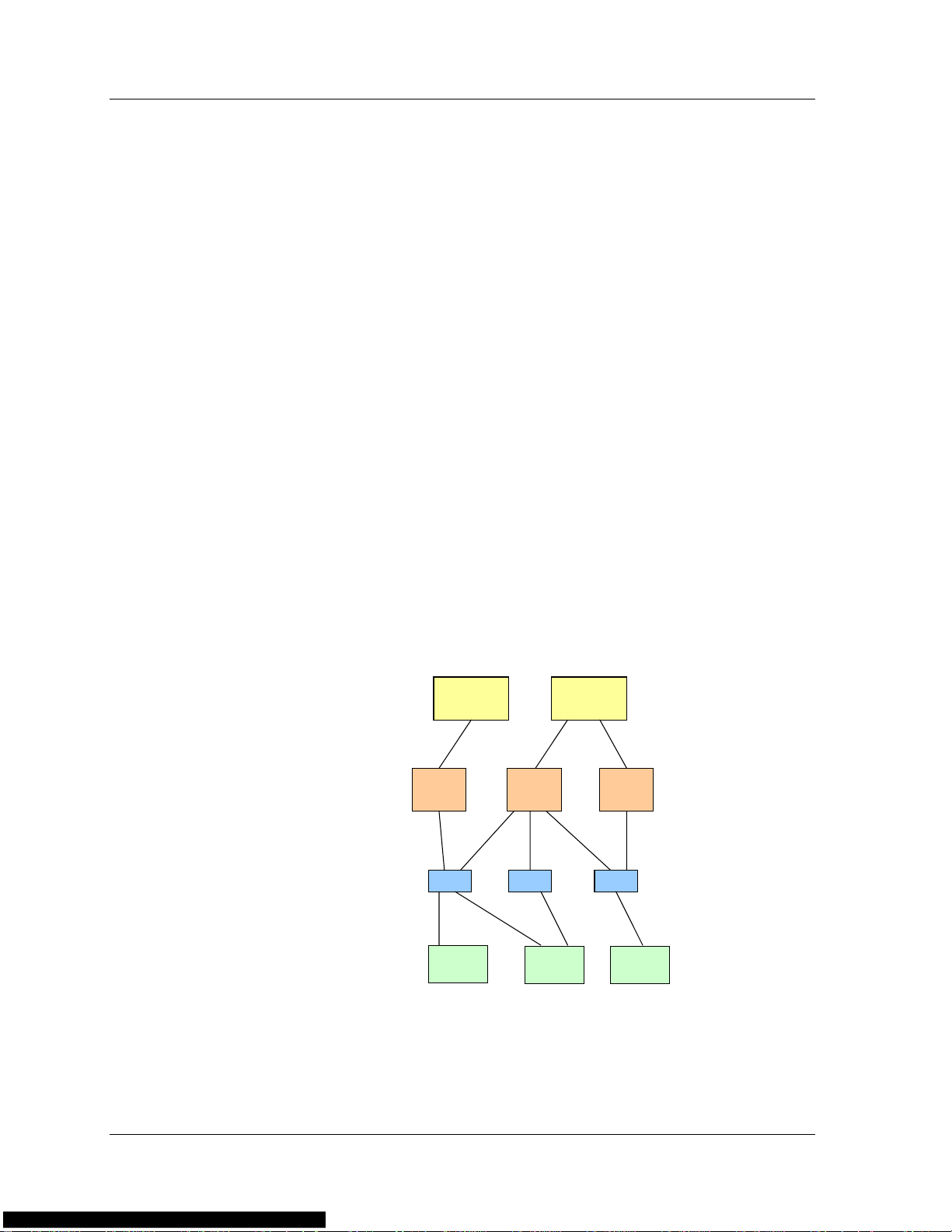
Traffic from the WAN is directed to the V irtual Server. The Virtual Server
provides Virtual Services when transferring packets to the RSG, which is
comprised of RSs. The following figure illustrates the conceptual load
balancing model.
Figure 1-1. The Conceptual Load Balancing Model
Virtual
Server
Virtual
Service
RSG RSG RSG
Real
Server
Virtual
Service
Real
Server
Virtual
Server
Virtual
Service
Real
Server
3 Avaya P330 Load Balancing Manager User Guide
Page 11

Firewall Load Balancing (FWLB)
This section provides information about Firewall Load Balancing,
including a general overview and detailed information about routing
and bridging firewalls.
FWLB Overview
Firewall Load Balancing intercepts all traffic between the LAN and the
WAN, and dynamically distributes the load among the available
firewalls, based on FWLB configuration. Using FWLB, all of the firewalls
are utilized concurrently, providing overall improved firewall
performance, scalability and availability.
The firewalls are the Real Servers, and the group of firewalls is the Real
Server Group. The firewall group is associated with a Virtual Service,
which is a routing or bridging firewall.
The load balancer:
• Balances traffic across two or more firewalls (up to 1024) in your
network, allowing the firewalls to work in parallel.
• Maintains state information about the traffic flowing through it
and ensures that all traffic between specific IP address source and
destination pairs flows through the same firewall.
• Performs health checks on all paths through the firewalls. If any
path is not operational, the load balancer diverts traffic away
from that path, maintaining connectivity across the firewalls.
Often, two load balancers are needed to support FWLB. One device is
deployed on the LAN side (internal) of the firewalls and another on the
WAN side (external). If a Demilitarized Zone (DMZ) is implemented to
allow remote access, a third load balancer must be deployed on the DMZ
side of the network. Additional devices can be added to provide
redundancy, eliminating any device or path as a single point of failure.
A vaya P330 Load Balancin g Manager supports both routing and bridging
firewalls. Routing firewalls may be transparent or non-transparent.
Avaya P330 Load Balancing Manager User Guide 4
Page 12
Chapter 1
Benefits of FWLB
FWLB allows you to:
• Maximize firewall productivity.
• Scale firewall performance.
• Eliminate the firewall as a single point of failure.
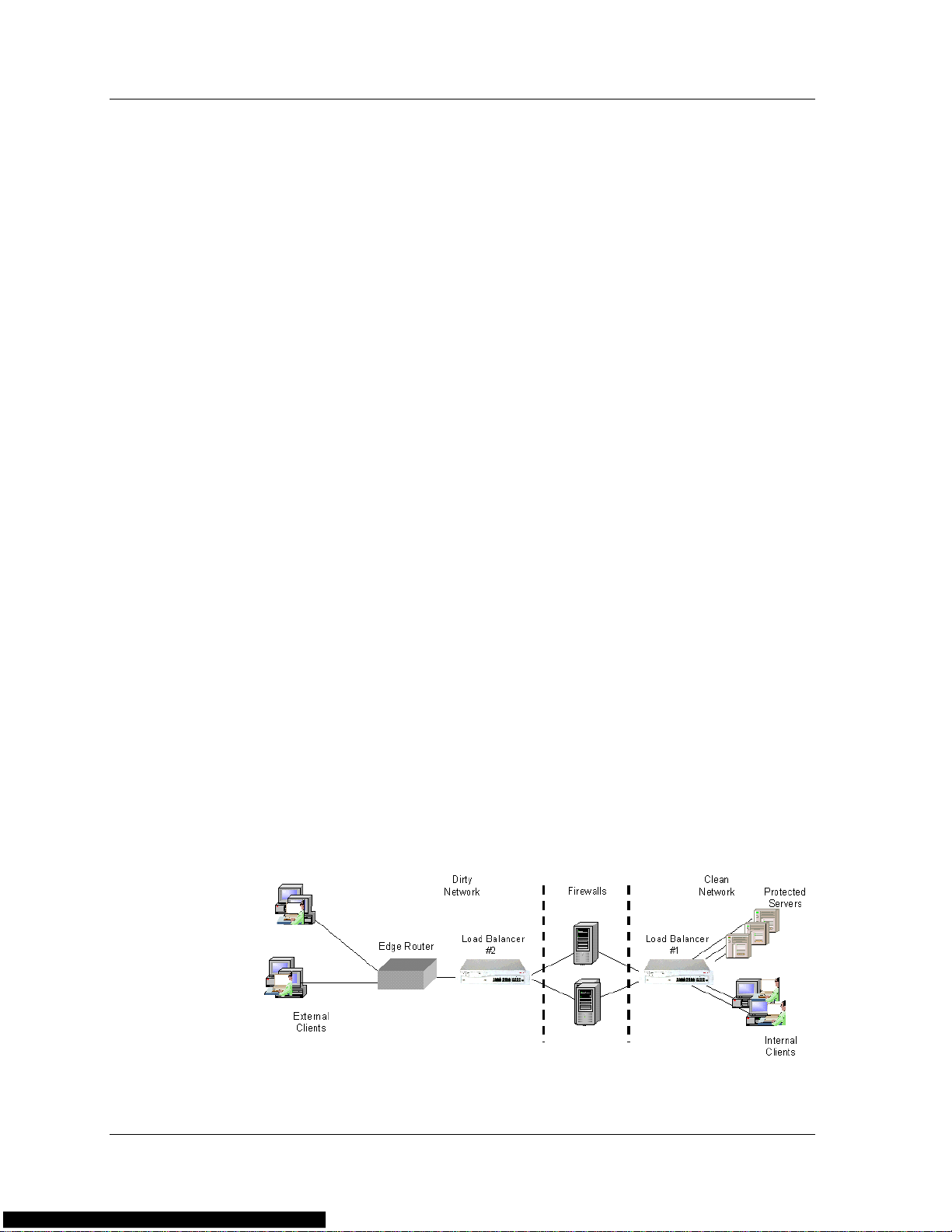
Transparent Routing Firewalls
For transparent FWLB, the load balancer receives a packet, makes a load
balancing decision, and forwards the packet to a firewall. The firewall
does not perform NAT on the packets; the source and destination IP
addresses are not changed.
Two load balancers are required for transparent FWLB, one on each side
of the firewalls. One device intercepts traffic between the WAN and the
firewall, and the second device intercepts traffic between the LAN and
the firewall.
Transparent routing firewalls act as a “next hop” device from the
perspective of the load balancer. After a firewall is selected in a load
balancing decision, normal routing to that firewall takes place.
The load balancers ensure that all packets belonging to a session pass
through the same firewall in both directions. The devices select a firewall
based on a symmetric hash function of the source and destination IP
addresses. This ensures that packets traveling between the same source
and destination IP addresses traverse the same firewall.
The following figure illustrates transparent FWLB.
Figure 1-2. Transparent Firewall Load Balancing
5 Avaya P330 Load Balancing Manager User Guide
Page 13
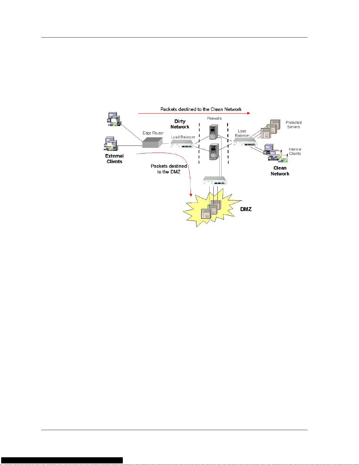
The load balancer enables you to route packets to a DMZ. A DMZ is a
portion of the client’s network, apart from the client’s LAN, where
remote access is allowed. After creating a DMZ, a third load balancer is
installed to route packets to the DMZ. The following figure illustrates
transparent FWLB with a DMZ.
Figure 1-3. Transparent FWLB With DMZ
Non-Transparent Routing Firewalls
Non-transparent routing firewalls are firewalls that support dynamic
NAT.
For non-transparent FWLB, the load balancer receives an outgoing
packet, makes a load balancing decision, and forwards the packet to a
firewall. The firewall keeps a bank of IP addresses and replaces the
source IP address of the outgoing packet with a unique, arbitrary IP
address from the bank. The firewall then forwards the packet to an edge
router which routes it to the correct destination on the WAN.
For incoming packets, the unique NA T address is use d as a destination IP
address to access the same firewall. The firewall performs reverse NAT by
replacing the NAT destination address with the actual destination
address (the client IP address), and then forwards the packet to the load
balancer, wh ich routes the packet to its destination. No load balancing is
performed on incoming packets.
For non-transparent FWLB, only one load balancer is required. The
device is positioned on the LAN (internal) side of the firewalls. Since the
firewalls perform NAT, a load balancer is not needed between the WAN
and the firewalls.
Avaya P330 Load Balancing Manager User Guide 6
Page 14
Chapter 1
In transparent FWLB, persistency is ensured by the load balancer. In
non-transparent FWLB, the firewalls ensure persistency through NAT,
and there is no need for the load balancer to intervene.
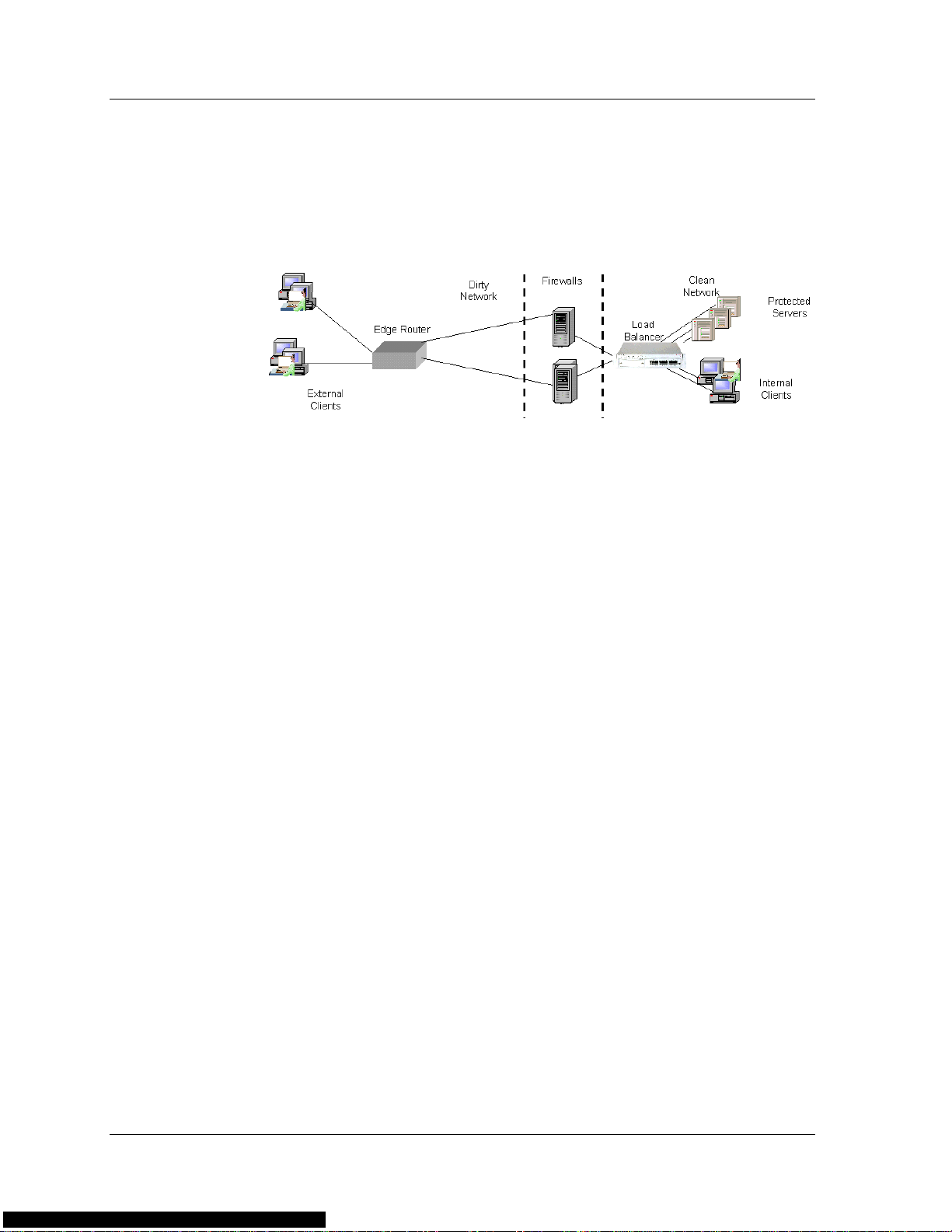
The following figure illustrates non-transparent FWLB.
Bridging Firewalls
Bridging firewalls are firewalls that do not perform forwarding at the IP
address layer , but rather appear as transparent bridges. Bridging firewalls
are transparent to devices inside and outside of the secured network.
The bridging firewalls do not have IP or MAC addresses to which traffic
is directed. Therefore, the firewalls must physically appear on the traffic
path.
Figure 1-4. Non-Transparent Firewall Load Balancing
For bridging FWLB, the load balancers must be positioned on both sides
of the firewalls. Each device load balances between IP address interfaces
of the peer device behind the firewall. For this to work, each firewall
must reside in a different VLAN and subnet, and the physical ports
connected to the firewalls must be on different VLANs as well. In
addition, for each VLAN, both load balancers must be in the same
subnet.
Each load balancer interface and the firewall connected to it reside in a
separate VLAN. This ensures persistency since all the traffic through a
particular firewall is contained in the firewall’s VLAN.
7 Avaya P330 Load Balancing Manager User Guide
Page 15
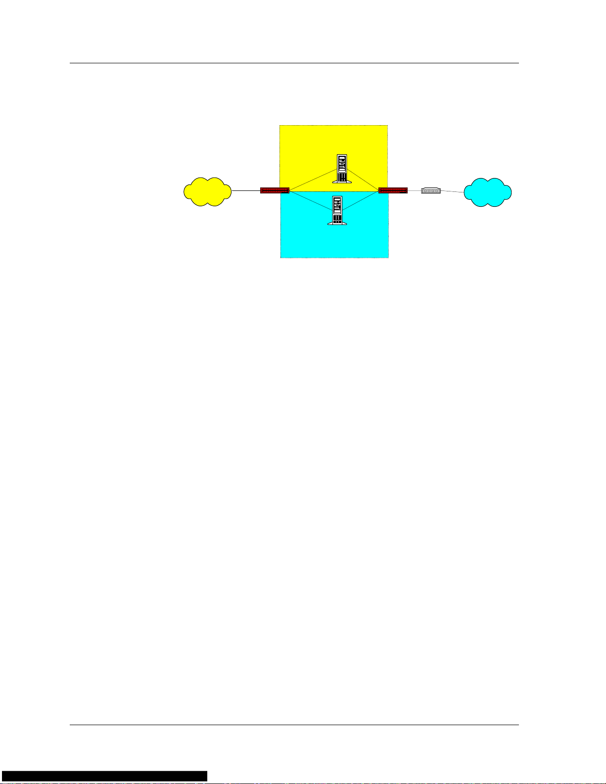
The following figure illustrates bridging FWLB.
Figure 1-5. Bridging Firewall Load Balancing
VLAN 1
LAN
Load Balancer
VLAN 2
Server Load Balancing (SLB)
This section provides information about Server Load Balancing,
including a general overview and detailed information about SLB.
SLB Overview
Server Load Balancing intercepts all traffic between clients and servers,
and dynamically distributes the load among the available servers, based
on the SLB configuration.
In a non-balanced network, each server provides access to specific
applications or data. Some of these applications may be in higher
demand than others. Servers that provide applications with higher
demand are over-utilized while other servers are under-utilized. This
causes the network to perform below its optimal level.
Firewall 1
Firewall2
Load Balancer
Access Router
Internet
Load balancing provides a solution by balancing the traffic among
several servers which all have access to identical applications and data.
This involves intercepting all traffic between clients and load-balanced
servers and dynamically distributing the load according to configured
schemes (metrics).
The load balancer acts as a Virtual Server to the outside world (the
WAN) and has a Virtual IP address.
Avaya P330 Load Balancing Manager User Guide 8
Page 16
Chapter 1
Benefits of SLB
SLB improves network performance by:
• Minimizing server response time.
• Maximizing server availability.
• Increasing server utilization and network bandwidth. This is
accomplished by balancing session traffic between the available
servers, according to rules established during configuration.
• Increasing reliability. If any server fails, the remaining servers
continue to provide services seamlessly.
• Increasing scalability. Server configuration can be performed
without disrupting the network.
Server Load Balancing
The server load balancer changes one of the source and destination IP
addresses. When a packet arrives from a client to a server, the load
balancer changes the destination IP from the Virtual IP address to the
Real IP address. When a packet is sent from a server to a client, the load
balancer changes the source IP address from the Real IP address to the
Virtual IP address.
The following figure illustrates Server Load Balancing:
Figure 1-6. Server Load Balancing
9 Avaya P330 Load Balancing Manager User Guide
Page 17

Direct Server Return (Triangulation)
Direct server return, or triangulation, is an additional implementation of
SLB. In standard SLB, the load balancer intercepts traffic between the
servers and clients in both directions. In triangulation, load balancing is
performed only on traffic from the clients to the server. Traffic from the
servers is returned to the client directly through a router without any
need for load balancing intervention.
For triangulation, the Real Servers must be specially configured. The
Real Servers must also be capable of receiving packets with the V irtual IP
address as the destination IP address, and of sending packets with the
Virtual IP address as the source IP address. The Virtual IP address should
be configured in the Real Servers as a “loopback” IP address, and the
router (not the load balancer) should be configured as the servers’
default gateway.
When the load balancer detects that a Real Server supports triangulation
and is configured properly, it does not change the destination IP address
of the packet. The Virtual IP address is left as the destination IP address,
and the packet does not undergo NAT.
Application Redirection (AR)
This section provides information about Application Redirection,
including a general overview, and detailed information about Cache
Redirection.
AR Overview
With the growing importance of the Internet as a source of information,
an organization's LAN may suffer from a degradation of performance
due to congestion of the router connecting the network to the Internet.
Since much information retrieved from the Web is either repeatedly
requested by a user or requested by multiple users, many organizations
implement a local caching mechanism to prevent unnecessary Internet
traffic. The local caches must be on the traffic path between the client
and the Internet router. As a result, all traffic, even traffic not intended
for the cache, passes through the cache.
Load balancing solves this problem by redirecting packets from their
original destination to an alternative server based on the Application
Redirection configuration. Cache Redirection is the most common
implementation of Application Redirection.
Avaya P330 Load Balancing Manager User Guide 10
Page 18

Chapter 1
Benefits of AR
By redirecting client requests to a local cache or application server, you
can increase the speed at which clients access information and free up
valuable network bandwidth.
Application Redirection improves network performance by:
• Providing faster client access to information.
• Increasing effective network bandwidth.
• Filtering traffic.
• Directing only suitable traffic to the local cache.
• Connecting and load balancing multiple caches.
• Performing the redirection process in a way that is transparent to
the client.
• Allowing redundant caches to be configured.
Cache Redirection
For Cache Redirection, the load balancer is positioned on the traffic
route and redirects traffic from the original destination to an alternative
cache server. The redirection process involves the following steps:
1. The load balancer checks whether the packet characteristics
2. The load balancer checks whether the application port is suitable
3. The load balancer routes the packet to the cache server instead of
4. The cache checks if it has the relevant information. If it does, it
comply with one of the defined filter rules. The user configures
rules to define which clients or destinations are to be redirected to
the cache.
for redirection (i.e., HTTP).
to the original destination on the Internet.
forwards the cached information to the client. If it does not have
the information, it retrieves the information from the Internet,
saves it to the cache, and then forwards the information to the
client.
The load balancer supports transparent caches. A transparent cache is a
cache that is capable of accepting packets not a ddressed to its IP add res s.
The cache usually uses NAT in its IP address stack, so the higher layers
can process packets not addressed to the cache’s IP address.
11 Avaya P330 Load Balancing Manager User Guide
Page 19
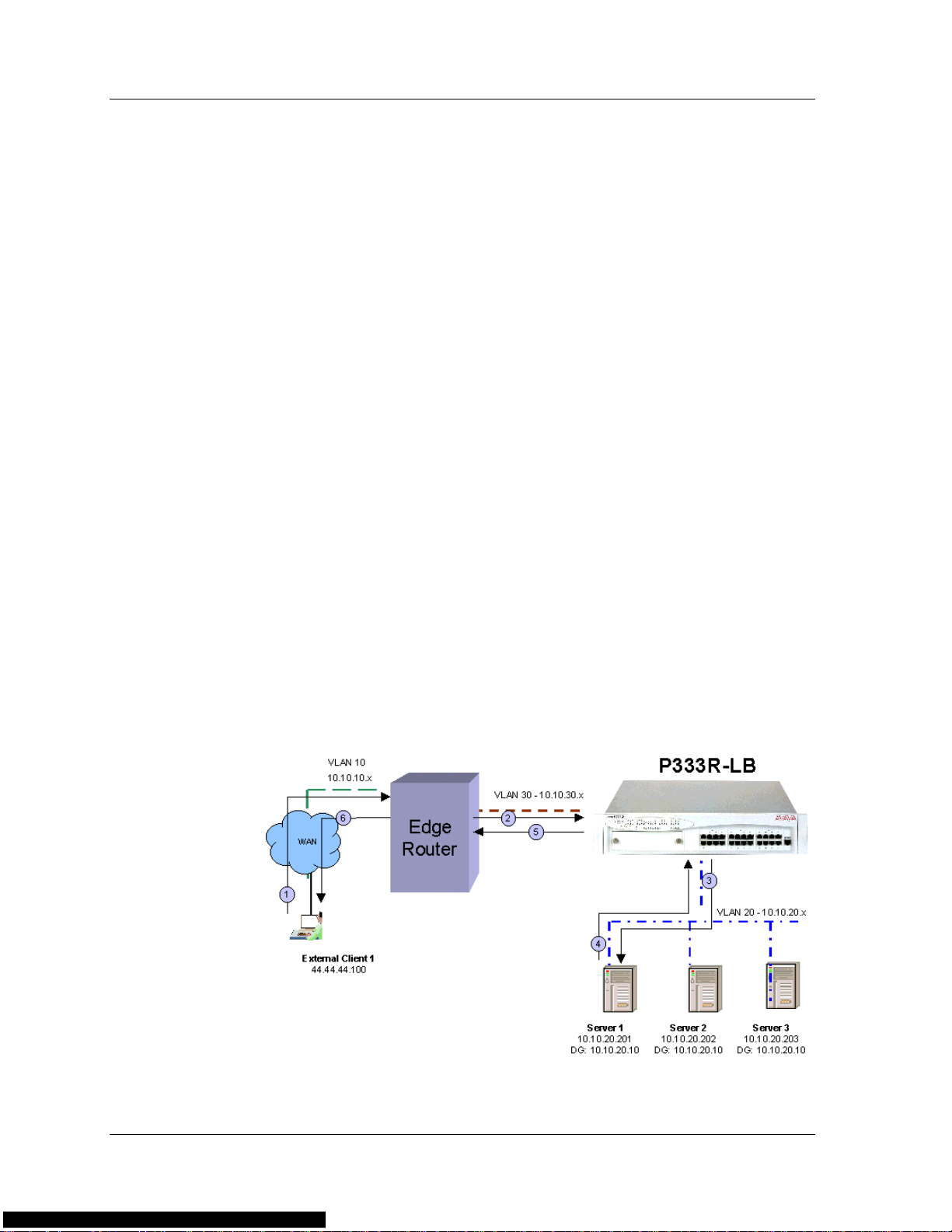
The following figure illustrates Cache Redirection.
Figure 1-7. Cache Redirection
In this figure, the sequence of events is as follows:
1. The user issues an HTTP request. The source IP address is the
user’s IP address and the destination IP address is the Web server’s
IP address.
2. The load balancer routes the packet to the local cache. The packet
still has the Web server’s IP address as its destination IP address.
3. If the cache has the required page, the cache returns the page to
the load balancer with the destination IP address of the client and
the source IP address of the Web server. If the cache does not
have the required page, the cache returns the packet to the load
balancer, and the load balancer routes the packet to the Web
server.
4. On the way back from the Web server, the load balancer routes
the packet to the cache.
5. The cache saves the packet and routes it back to the load balancer.
6. The load balancer sends the page to the user.
A client's request for a Web page and the cache's request for a Web page
have the same source and destination IP addresses. To distinguish
between them, the load balancer uses separate VLANs for clients and the
cache. If the request is on the clients' VLAN, the load balancer forwards
the request to the cache. If the request is on the cache's VLAN, the load
balancer forwards the request to the WAN.
Similarly , the WAN’s return of a Web page and the cache's forwarding of
a Web page to a client have the same source and destination IP
addresses. To distinguish between them, the load balancer uses separate
VLANs for clients and the cache. If the response is on the cache’s VLAN,
the load balancer forwards the response to the cache. If the response is
on the clients' VLAN, the load balancer forwards the response to the
client.
Avaya P330 Load Balancing Manager User Guide 12
Page 20

Chapter 1
Combination of Applications
You can enable the P333R-LB to use various applications concurrently.
For example, it is possible to configure the same P333R-LB to perform
Server Load balancing for an Intranet web-server, Application
Redirection for web traffic that is Internet-bound, and Firewall Load
Balancing for traffic that is Internet-bound.
In some cases, the same “type” of traffic can be given two different
actions by the load balancer . In these situations, it is necessary to tell the
load balancer which action to choose. In the example described above,
web traffic to the intranet server can be configured to either be directed
to the web cache, or bypass the web cache and directly access the
Intranet server. The latter configuration will save the web cache
resources to deal with Internet-bound traffic.
You can specify the preferred action as one of the following:
• Configure SLB to take precedence over AR.
• AR can take precedence over SLB.
• Configure AR filters to redirect traffic from client/server
addresses, using wildcards.
• Configure AR filters to specify which traffic not to redirect
(“no-ar” as service) from specific client/server addresses, using
wildcards.
Load Balancing Metrics
There are several methods, or metrics, that a load balancer can use to
distribute traffic among multiple servers, firewalls or caches. These
metrics tell the load balancer which Real Server should receive each
session.
Some commonly used metrics are:
• Round Robin
• Hash
• MinMiss Hash
• Weighted Real Servers
13 Avaya P330 Load Balancing Manager User Guide
Page 21
Round Robin
Hash
Using Round Robin, the load balancer issues sessions to each RS in turn.
The first RS in the group receives the first session, the second RS receives
the next session, and so on. When all the RSs receive a session, the
issuing process starts over with the first RS. Round Robin ensures that
each RS receives an equal number of sessions.
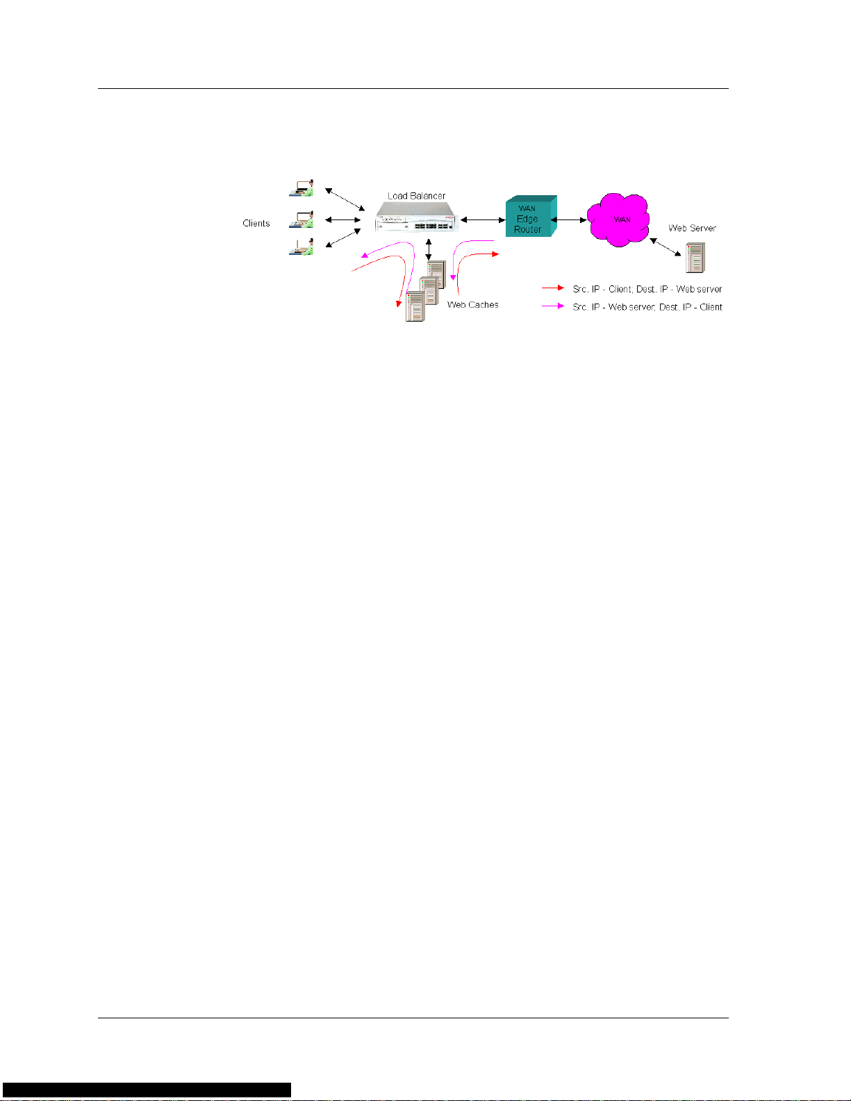
Using the Hash metric, sessions are distributed to RSs using a predefined
mathematical hash function. The hash function is performed on a
specified parameter. The source IP address, destination IP address, or
both are used as the hash function input.
The load balancer creates a list of all the currently available RSs. The
result of the hash function is used to select an RS from the list. Any
given parameter always gives the same hash result, providing natural
persistency.
If an RS is removed or added to the group, persistency is broken. This
occurs since the order of the RSs in the list changes, but the hash still
points to the same list entries. The following figure illustrates how a loss
of persistency occurs when an RS becomes non-operational:
Figure 1-8. Hash Metric - Loss of Persistency
In the above figure, when Server 2 becomes non-operational, the list of
available servers is readjusted, causing a lack of persistency. However, if
Server 2 becomes operational again, the list of available servers is
restored to its original order, and persistency is recovered.
Avaya P330 Load Balancing Manager User Guide 14
Page 22
Chapter 1
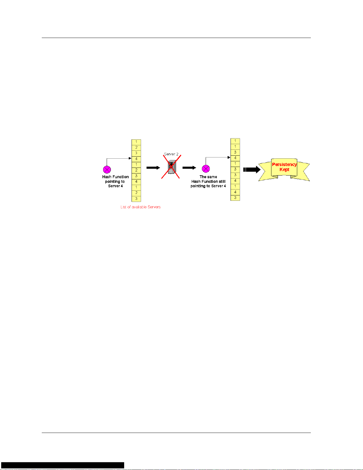
MinMiss Hash
MinMiss hash distributes sessions to RSs in the same way as the Hash
metric. However, MinMiss hash retains persistency even when an RS is
removed from the group. When an RS fails or is removed, the load
balancer does not change the position of all the RSs in the list. Instead, it
redistributes the remaining RSs to the list entries freed by the failing RS.
The following figure illustrates how persistency is retained when an RS
becomes non-operational.
Figure 1-9. MinMiss Metric - Persistency Retained
In the above figure, when Server 2 becomes non-operational, the list of
available servers is not readjusted. Only the list entries that are now
empty are replaced with other available servers. Therefore, persistency is
retained for all available servers. However, if Server 2 becomes
operational again, the list of available servers is recalculated so that the
smallest number of servers is affected. The list is not restored to its
original configuration. As a result, persistency is only partially recovered.
Weighted Real Servers
You can assign weights to RSs to enable faster RSs to receive a larger
share of sessions. This minimizes overloading and maximizes
functionality.
If you assign a weight to an RS, the sessions are distribute d to the RSs in
the metric chosen (Round Robin, Hash or MinMiss). However, the
weighted RS is assigned a larger share of sessions. For example, if you
assign a weight of 20 to one RS and leave the default weight (10)on the
second RS, the weighted RS receives 2 sessions for each session directed
to the second RS. This is useful for RSs with different bandwidths or
processor speeds.
15 Avaya P330 Load Balancing Manager User Guide
Page 23

Health Check
The load balancer constantly checks the RSs to ensure that each RS is
accessible and operational. An RS that fails the health check is
automatically removed from the load balancer’s internal list of currently
available RSs, and traffic is redirected to other available RSs.
There are several types of health check methods that the load balancer
can use, including:
For FWLB, checking the firewalls is insufficient. The health checks must
be performed on the entities beyond the firewalls as well. In order to
ensure that the health check packets traverse the same firewall in both
directions, the packet’s source and destination IP addresses should be the
IP addresses of the load balancer interfaces on each side of the firewall.
For each load balancer, both the local and remote addresses must be
configured. In addition, the load balancers on both sides of the firewall
must be configured symmetrically.
• ICMP Ping - Each RS is periodically pinged. If no answer is
received, the RS is not operational.
• TCP Port Checking - A TCP connection is periodically opened
to each RS, checking for successful completion of the connection.
Persistency
For non-transparent FWLB (with NAT), there is only one load balancer.
In this case, you must configure an IP address beyond the firewall as the
health check address. Like other non-transparent FWLB sessions, the
health check session returns through the same firewall according to the
NAT address it was given.
Persistency is the maintenance of the connection between the server and
the client over multiple sessions. Persistency ensures that all traffic from
the client is directed to the same RS.
Persistency is achieved by using naturally persistent load balancing
metrics (such as Hash or MinMiss hash) or by forcing persistent load
balancing decisions on non-persistent load balancing metrics (such as
Round Robin). Persistency is forced by storing the history of the latest
decisions in a cache for a limited time, and then sending the packets to
the appropriate RS according to the previous load balancing decisions.
Avaya P330 Load Balancing Manager User Guide 16
Page 24

Chapter 1
Persistency is achieved by opening a new entry for a server group based
on the following:
• New entry on source IP address - All sessions from a specific
source are directed to the same RS. This is useful for applications
where client information must be retained on the RS between
sessions.
• New entry on destination IP address - All sessions to a
specific destination are directed to the same RS. This is useful for
caching applications to maximize successful cache hits when the
information is not duplicated between RSs.
• New entry on source IP and destination IP addresses - All
sessions from a given source to a given destination are directed to
the same RS. This is useful for Firewall Load Balancing, since it
ensures that the two unidirectional flows of a given session are
directed through the same firewall.
Additional Persistency Schemes
Using the P333R-LB, you can configure a Real Server to backup one or
more primary Real Servers. A backup Real server is not used unless the
primary Real Server is down.
You can also configure a Real Server Group (RSG) to backup one or
more primary RSGs. A backup RSG can run a different service than the
primary RSG while providing backup to all of the primary RSG’ s services.
Similar to the Real Server, the backup RSG is not used unless all Real
Servers in the RSG are down.
17 Avaya P330 Load Balancing Manager User Guide
Page 25

2
Getting Started with Avaya
P330 Load Balancing Manager
This chapter provides instructions on how to start A vaya Load Balancing
Manager and an overview of the user interface. It includes the following
topics:
• Starting Avaya Load Balancing Manager - Instructions on
how to start Avaya P330 Load Balancing Manager.
• The User Interface - An introduction to Avaya P330 Load
Balancing Manager’s user interface.
• Saving Configuration Changes - Instructions for applying and
committing changes to the load balancing configuration.
• Searching for Load Balancing Components - Instructions on
how to search for RSs and RSGs in Avaya P330 Load Balancing
Manager.
Starting Avaya Load Balancing Manager
To start Avaya P330 Load Balancing Manager for the Avaya P330:
1. Click the
A list of P333R-LB module IP addresses appears in the Tree View
of the Avaya P330 Manager.
* Note: In order that the Load Balancing Manager tab appear, at least
one of the interfaces should be configured on the load
balancer. For more information , refer to P333R-LB User Guide
or P333R-LB Quick Start.
Load Balancing Manager
tab in the A vaya P330 Manager.
Avaya P330 Load Balancing Manager User Guide 18
Page 26
Chapter 2
The User Interface
The user interface consists of the following elements:
• Menu Bar - Menus for accessing Avaya Load Balancing Manager
functions (refer to Appendix A, Menus).
• Toolbar - Toolbar buttons for accessing Avaya Load Balancing
Manager functions.
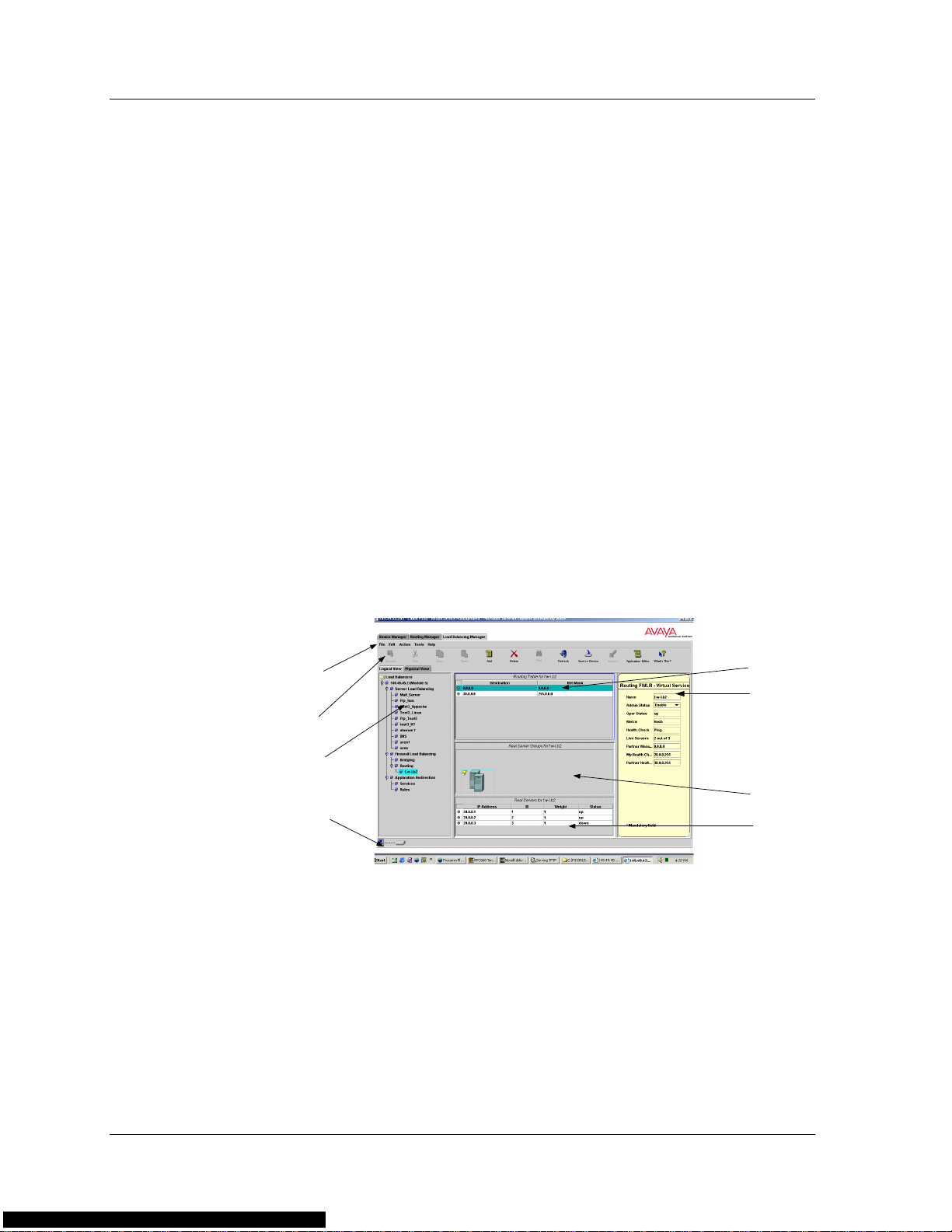
• Logical or Physical View - Depending on the tab selected, the
application displays one of the two views.
— Logical View - A logical representation of the network
showing Virtual Servers and Services and their associated
RSGs and RSs. The Logical View includes a hierarchical Tree
Area, Table Area, RSG Area, RS Area, and Form Area. The
various areas display information related to the element
selected in the Tree Area.
Menu Bar
Toolbar
Tree Area
Status Bar
The following figure shows the Logical View of the user
interface, with its various parts labeled.
Figure 2-1. The User Interface - Logical View
Table Area
Form Area
RSG Area
RS Area
19 Avaya P330 Load Balancing Manager User Guide
Page 27
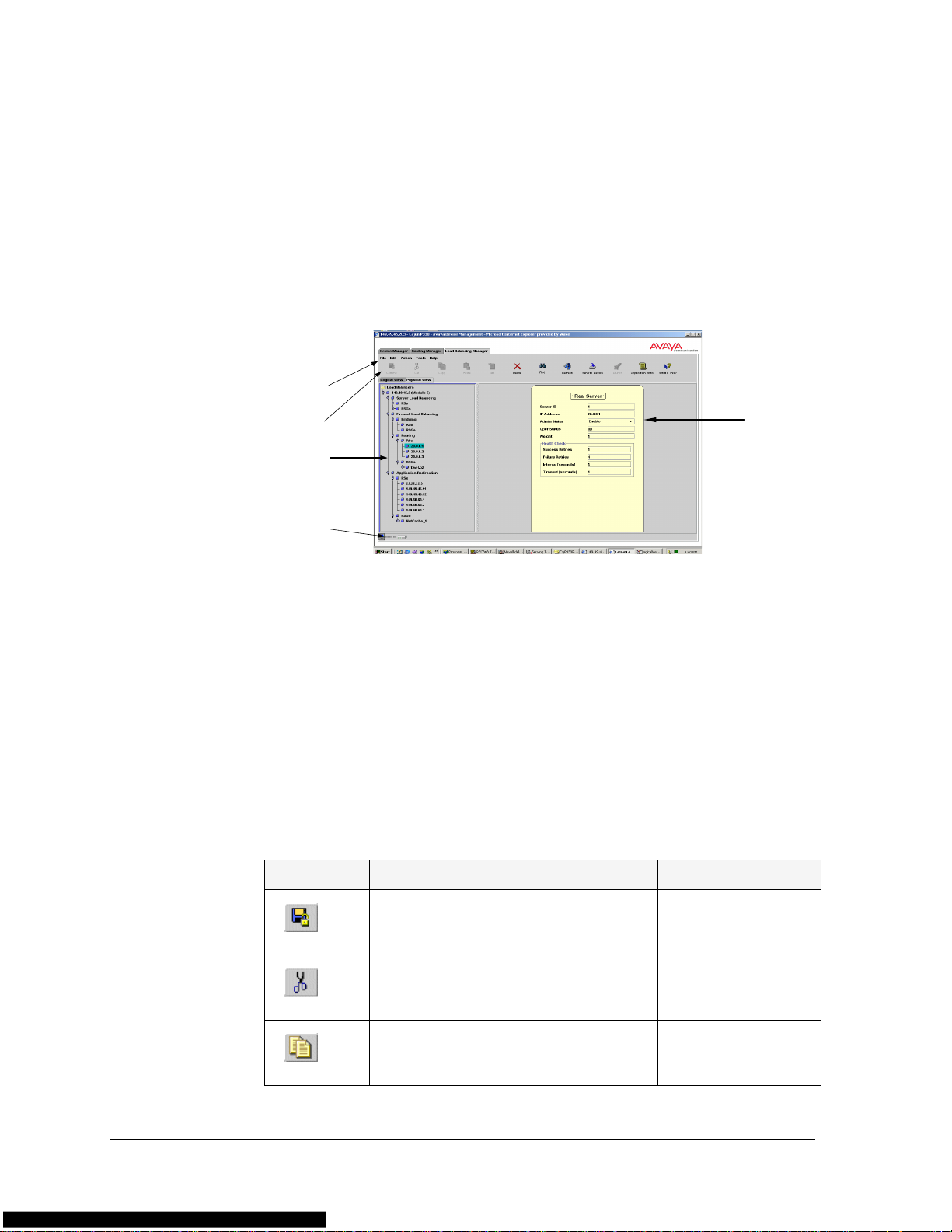
— Physical View - A physical representation of the P333R-LB
devices in the network showing RSs and RSGs. The Physical
View includes a Tree Area and a Form Area. The Form Area
displays information related to the element selected in the
Tree Area.
The following figure shows the Physical View of the user
interface, with its various parts labeled.
Figure 2-2. The User Interface - Physical View
Menu Bar
Toolbar
Toolbar
Tree Area
Status Bar
Form Area
• Status Bar - An area at the bottom of the screen that displays the
communication status between Avaya Load Balancing Manager
and the network.
The toolbar provides shortcuts to Avaya Load Balancing Manager’s main
functions. The following table describes the buttons on the toolbar and
gives the equivalent menu options.
Table 2-1. Toolbar Buttons
Buttons Description Menu Item
Saves configuration changes to the
File > Commit
device.
Cuts a rule from a table to the
Edit > Cut
application clipboard
Copies a rule from a table to the
Edit > Copy
application clipboard.
Avaya P330 Load Balancing Manager User Guide 20
Page 28

Chapter 2
Table 2-1. Toolbar Buttons (Continued)
Buttons Description Menu Item
Pastes a rule from the application
clipboard.
Adds a new entity.
Deletes the selected entity.
Opens the Find dialog box.
Refreshes the current view from
the device. Changes that were not
applied or saved to the device are
lost.
Applies current modifications to
the device.
Launches another device manager.
Edit > Paste
Edit > Add
Edit > Delete
Edit > Find
Action > Refresh
Action > Send to
Device
Tools > Launch
Opens the Application Editor.
Opens the Proxy IP Editor.
Opens the Health Check Editor.
Provides context-sensitive on-line
Tools > Application
Editor
Tools > Proxy IP
Editor
Tools > Health
Check Editor
Help > What’s This?
help.
When you place the cursor on a toolbar button for one second, a tooltip
appears with the name of the button.
21 Avaya P330 Load Balancing Manager User Guide
Page 29

Logical View
The Logical View displays a logical representation of the network. The
Logical View includes the following areas (these areas are discussed in
more detail below):
• Logical Tree Area - Displays a hierarchical representation of the
network.
• Table Area - Displays various tables.
• RSG Area - Displays RSGs.
• RS Area - Displays RSs.
• Form Area - Displays Properties Sheets.
The various areas are synchronized. When you select an element in one
area, the other areas display related information. As you move the focus
between the different areas and select different elements within the
areas, the information displayed in the other areas changes.
In the Logical View, the focus is always on one of the Logical Tree, T able,
RSG, or RS Areas. You can only make changes to the area in focus. The
area in focus is framed in blue, and an item selected in the area in focus
appears dark green. An item selected in an area that is not in focus
appears cyan.
Logical Tree
Area
The Logical Tree Area is a hierarchical representation of the structure
and functions performed by the load balancers in the network. To select
a device or any of its components, click the appropriate icon in the
Logical Tree Area.
The highest level in the Logical Tree Area represents the IP address of the
device. The lower levels show load balancer modules, load balancing
applications (FWLB, SLB or AR), Virtual Servers, firewall services, rules,
and services. The type of information displayed in the lower levels of the
Logical Tree Area depends on which load balancing application is
selected.
To expand the view of a collapsed element in the tree or to collapse an
expanded element in the tree:
Double-click the element you want to expand or collapse.
Or
Click the handle next to the element.
Avaya P330 Load Balancing Manager User Guide 22
Page 30

Chapter 2
Table Area
RSG Area
RS Area
Form Area
Physical View
The Table Area displays information related to the selected item in the
Logical Tree Area. Depending on which item is selected in the Logical
Tree Area, the Table Area displays the Virtual Services Table, the Routing
Table, the Rules List, or the Services List.
The RSG Area displays the RSGs that are related to the selected element
in the Logical Tree Area or in the Table Area.
The RS Area displays the RSs that are connected to the RSG selected in
the RSG Area.
The Form Area displays the Properties Sheet of the element selected in
the area in focus. For example, if the focus is on the Table Area and you
select an item from the Virtual Se rvices T able, the Form Area displays the
Properties Sheet of the selected Virtual Service.
The Form Area never receives the focus, but you can edit the Properties
Sheet displayed in the Form Area.
Physical T ree
Area
The Physical View displays a representation of the physical P333R-LB
modules in the network. The Physical View includes the Physical Tree
Area and the Form Area.
Some configuration changes can only be made using the Physical View.
For example, if you delete an entity in the Logical View, the link to the
entity is deleted, but the entity is still available for configuring at a later
time. To delete the entity completely, you must delete it from the
Physical View. An entity deleted from the Physical View is unavailable
for further use and must be redefined.
The Physical Tr ee Area displays RSs and RSGs. When you select an RS or
RSG from the Physical Tree Area, the Form Area displays the Properties
Sheet related to the selected RS or RSG.
To expand the view of a collapsed element in the tree or to collapse an
expanded element in the tree:
Double-click the element you want to expand or collapse.
Or
Click the handle next to the element.
23 Avaya P330 Load Balancing Manager User Guide
Page 31

Virtual Form
Area
Status Bar
The Form Area displays the Properties Sheet of the element selected in
the Physical Tree Area.
The Status Bar shows the communication status between Avaya Load
Balancing Manager and a specific device in the network.
The following table shows the possible communication statuses with
their corresponding graphics, and gives a short explanation for each
status.
Table 2-2. Communication Statuses
Graphic Status Description
Ready The application is ready to
communicate with a load
balancing device.
CommunicatingThe application is currently
communicating with a load
balancing device.
Communicatio
n Error
Saving Configuration Changes
Configuration changes do not take effect until you apply or save the
changes to the device. There are two levels of applying configuration
changes to the load balancing device:
• Applied Changes - Changes are applied to the device, but are
not saved. Applied changes affect the present network
configuration. However , these changes are lost when the device is
reset.
• Committed Changes - Changes are saved to the device.
Committed changes are maintained even when the device is
reset.
The last attempted
communication with the load
balancing device was not
successful.
Avaya P330 Load Balancing Manager User Guide 24
Page 32

Chapter 2
Applied Changes
After finalizing all configuration changes, the changes must be applied to
the device. Applied changes affect the current configuration but are not
saved when the device is reset.
To apply the changes to the device:
Click
Send to Device
Or
.
Select
applied to the device.
The applied changes remain in effect until the device is reset. When the
device is reset, it is configured with the last committed configuration. All
changes applied but not committed are lost.
When you switch the focus from one screen area to another without
applying changes, a message prompts you to apply the configuration
changes that you made to the device. Changes to Properties Sheets are
stored locally until you apply the changes to the device. Therefore, no
message appears when you switch from one Properties Sheet to another.
Committed Changes
To make configuration changes permanent, the changes must be
committed (saved) to the device.
To commit the configuration to the device:
Click
Action > Send to Device
Commit
.
. The configuration changes are
Or
Select
* Note: The commit operation may take up to 20 seconds. Avoid
25 Avaya P330 Load Balancing Manager User Guide
File > Commit
running other operations while committing changes to the
device.
. The changes are saved to the device.
Page 33

Searching for Load Balancing Components
Avaya Load Balancing Manager allows you to search for RSs or RSGs in
the Physical Tree Area.
To search for a load balancing component:
1. Click
2. Enter the IP address of the RS or the name of the RSG to search
Find
.
Or
Select
for, and enter the RLB ID (the slot number of the load balancer
module in the stack).
Edit > Find
. The Find dialog box opens.
Figure 2-3. Find Dialog Box
Find
3. Click
— If the requested RS or RSG is found, the element is selected in
— If the requested element is not found, a message appears.
Avaya P330 Load Balancing Manager User Guide 26
. Avaya Load Balancing Manager searches for the item.
the Physical Tree Area.
Page 34

3
Configuring Firewall Load
Balancing
This chapter provides instructions on how to configure Firewall Load
Balancing (FWLB). It includes the following topics:
• Firewall Load Balancing Configuration Overview - An
overview of the steps involved in configuring FWLB.
• Defining a Firewall Service - Instructions on how to define a
firewall service.
• Editing the Routing Table - Instructions on how to add and
edit entries in the service’s Routing Table.
• Defining RSGs and RSs for FWLB - Instructions on how to
define RSGs and RSs for Firewall Load Balancing.
• Editing the Properties Sheets for FWLB - Instructions on
how to enter information in the Properties Sheets for FWLB
entities.
• Launching Another Avaya Device Manager - Instructions on
how to launch another Avaya P330 Load Balancing Manager for
identical configuration of two devices.
Avaya P330 Load Balancing Manager User Guide 27
Page 35

Firewall Load Balancing Configuration Overview
Configuring Avaya P330 Load Balancing Manager for FWLB involves
several steps. This section provides an overview of the entire process,
and the following sections explain each step in detail.
To configure Avaya P330 Load Balancing Manager to perform FWLB:
1. Define one or more firewall services (refer to “Defining a Firewall
Service” on page 29).
2. Add and edit entries in the Routing Table (refer to “Editing the
Routing Table” on page 30).
3. Define an RSG (refer to “Defining RSGs and RSs for FWLB” on
page 31).
4. Define one or more RSs (refer to “Defining RSGs and RSs for
FWLB” on page 31).
After you define a new FWLB element, click
configuration changes to the device. To save the configuration changes,
click
Commit
refer to “Saving Configuration Changes” on page 24.
. For more information about applying and saving changes,
Send to Device
to apply the
Avaya P330 Load Balancing Manager User Guide 28
Page 36

Chapter 3
Defining a Firewall Service
The first step in configuring FWLB is defining a firewall service. A
firewall service is a Virtual Service for FWLB (refer to “Load Balancing
Elements” on page 3). A firewall service may be a routing firewall
service or a bridging firewall service.
To define a firewall service:
1. In the Logical Tree Area, select FWLB from the load balancer
module you are currently configuring.
2. Select Bridging or Routing, depending on the type of firewall you
are configuring.
Add
3. Click
Or
.
Select
4. Enter information about the new firewall service in the Routing
Table and the Properties Sheet. For more information about
entering information in the Routing Table and Properties Sheet,
refer to “Editing the Routing Table” on page 30 and “Editing the
Properties Sheets for FWLB” on page 31.
When you select a firewall service from the Logical Tree Area, the Table
Area displays the Routing Table to the selected service, the RSG Area
displays the related RSGs, and the Form Area displays the service’s
Properties Sheet.
To modify an existing firewall service:
1. Select the service from the tree.
2. Edit the information in the Routing Table and Properties Sheet.
To delete a firewall service:
1. Select the service from the tree.
2. Click
Edit > Add
Delete
. A new firewall service is added to the tree.
.
Or
Select
29 Avaya P330 Load Balancing Manager User Guide
Edit > Delete
. The firewall service is deleted.
Page 37

Editing the Routing Table
The Table Area displays the Routing Table when a firewall service is
selected in the Logical Tree Area. The Routing Table displays destination
and network mask information for the firewall service.
Figure 3-1. Routing Table
The following table lists the fields in the Routing Table and their
descriptions:
Field Description
Table 3-1.
Destination
Net Mask
To add an entry to the Routing Table:
1. In the Logical Tr ee Area, select a firewall service you want to add a
routing entry to.
2. Click anywhere inside the Table Area so that the Table Area
receives the focus.
3. Click
4. Enter information in the fields of the new row.
To delete an entry in the Routing Table:
1. Select the entry you want to delete.
Add
Or
Select
The destination network IP address of this route. An
IP address of 0.0.0.0 denotes a default router.
The destination network mask of this route.
.
Edit > Add
. A new row is added to the Routing Table.
2. Click
Avaya P330 Load Balancing Manager User Guide 30
Delete
Or
Select
.
Edit > Delete
. The entry is deleted.
Page 38

Chapter 3
* Note: When the focus is on the Routing T able, the Properties Sheet
displayed in the Form Area is not related to the selected
entry in the Routing Table. Rather, the Properties Sheet is
related to the firewall service that is selected in the tree.
Defining RSGs and RSs for FWLB
After you define a firewall service, you can define the RSGs that are
connected to the service. The RSG Area displays the RSGs related to the
firewall service selected in the Logical Tree Area. You can add or delete
RSGs for each firewall service.
The RS Area displays the RSs belonging to the RSG selected in the RSG
Area. You can add or delete RSs for each RSG.
For more information about defining and deleting RSGs and RSs, refer to
Chapter 6, Real Server Groups and Real Servers.
Editing the Properties Sheets for FWLB
When you add a new entity for load balancing configuration, the Form
Area displays the Properties Sheet of the new entity . The following figure
displays a Routing Firewall Properties Sheet.
Figure 3-2. Routing Firewall Properties Sheet
31 Avaya P330 Load Balancing Manager User Guide
Page 39

Some fields in the Properties Sheet are Read Only and cannot be edited
and other fields are Read/Write. Enter information in all the Read/Write
fields. When you click
information to the device, the device updates the Properties Sheet’s Read
Only fields with the correct information.
The Form Area displays the Properties Sheet of the selected item in the
area in focus. The Form Area never receives the focus, but you can edit
the Properties Sheet displayed in the Form Area.
As the focus switches between the various areas, the Properties Sheet
displayed in the Form Area changes. Any new information you entered
is not lost when the Properties Sheet changes. This information is stored
locally until you apply the changes to the device.
The following tables list the fields in the various FWLB Properties Sheets.
Module Properties Sheet
The following table lists the fields in the Module Properties Sheet and
their descriptions.
Send to Device
to apply the new configuration
Table 3-2. Module Properties Sheet Fields
Field Description
IP Address
Name
Type
Contact
Location
SLB-AR
Precedence
The IP address of the module.
A user-defined name for the module.
The module type.
The name of the person responsible for the module.
The location of the module.
The precedence order of the various load balancing
applications. The Applications Precedence value is
used when more than one load balancing application
may be applied to a given packet.
Select a precedence order from the drop-down list.
App-Redir
enable/disable
Firewall LB
enable/disable
Server LB
enable/disable
An enable/disable toggle for Application Redirection.
An enable/disable toggle for Firewall Load
Balancing.
An enable/disable toggle for Server Load Balancing.
Avaya P330 Load Balancing Manager User Guide 32
Page 40

Chapter 3
Routing Firewall Properties Sheet
The following tables list the fields in the Routing Firewall Properties
Sheet and their descriptions.
Table 3-3. Routing Firewall Properties Sheet Fields
Field Description
Name
Admin Status
Operational
Status
Metric
Health Check
Live Servers
Partner
Management IP
My Health Check
IP
Partner Health
Check IP
A user-defined name for the service.
The user-defined status of the service. Available
options are enable and disable.
The operational status of the service. This field is
read only. The possible values are:
• Up - the paths are operational
• Down - all paths through the firewall are not
operational, or no paths are configured.
The metric used in load balancing decisions.
For more information about metrics, refer to “Load
Balancing Metrics” on page 13.
The health check method used to check the validity
of all paths through the firewall.
The number of paths that are valid for this service.
The management IP address of the load balancer
operating on the other side of the firewall.
The IP address from where the health check packet
originates.
The IP address to which the health check packet is
directed.
33 Avaya P330 Load Balancing Manager User Guide
Page 41

Bridging Firewall Properties Sheet
The following tables list the fields in the Bridging Firewall Properties
Sheet and their descriptions.
Table 3-4. Bridging Firewall Properties Sheet Fields
Field Description
Name
Admin Status
Operational
Status
Metric
Health Check
Live Servers
Partner
Management IP
A user-defined name for the service.
The user-defined status of the service. Available
options are:
• Enable
• Disable
The operational status of the service. This field is
read only. The possible values are:
• Up - the paths are operational
• Down - all paths through the firewall are not
operational, or no paths are configured.
The metric used in load balancing decisions.
For more information about metrics, refer to “Load
Balancing Metrics” on page 13.
The health check method used to check the validity
of all paths through the firewall.
The number of paths that are valid for this service.
The management IP address of the Load Balancing
device operating on the other side of the firewall.
Launching Another Avaya Device Manager
For transparent and bridging FWLB, two load balancers are necessary,
one for each side of the firewalls. The two devices must be identically
configured. Avaya P330 Load Balancing Manager allows you to launch
the device manager of another load balancer so that you can configure
both devices the same way.
To launch another device manager:
1. Select a Bridging FWLB component.
Avaya P330 Load Balancing Manager User Guide 34
Page 42

Chapter 3
2. Click
Launch
Or
Select
Tools > Launch
. Avaya P330 Load Balancing Manager
launches on the selected device.
* Note: This feature is not available when you run Avaya P330 Load
Balancing Manager from the Web.
35 Avaya P330 Load Balancing Manager User Guide
Page 43

4
Configuring Server Load
Balancing
This chapter provides instructions on how to configure Server Load
Balancing (SLB). It includes the following topics:
• Server Load Balancing Configuration Overview - An
overview of the steps involved in configuring SLB.
• Defining a Virtual Server - Instructions on how to define a
Virtual Server.
• Defining a Virtual Service - Instructions on how to define a
Virtual Service.
• Defining RSGs and RSs for SLB - Instructions on how to
define RSGs and RSs.
• Defining RSGs and RSs for SLB - Instructions on how to
define RSGs and RSs.
• Editing the Properties Sheets for SLB - Instructions on how
to edit the Properties Sheets for Server Load Balancing entities.
Avaya P330 Load Balancing Manager User Guide 36
Page 44

Chapter 4
Server Load Balancing Configuration Overview
Configuring Avaya P330 Load Balancing Manager for SLB involves
several steps. This section provides an overview of the entire process,
and the following sections explain each step in detail.
To configure Avaya P330 Load Balancing Manager to perform SLB:
1. Define one or more Virtual Servers (refer to “Defining a Virtual
Server” on page 38).
2. Define one or more Virtual Services (“Defining a Virtual Service”
on page 39).
3. Define one or more RSGs (refer to “Defining RSGs and RSs for
SLB” on page 47).
4. Define one or more RSs (refer to “Defining RSGs and RSs for SLB”
on page 47).
After you define a new SLB element, click
configuration changes to the device. To save the configuration changes,
Commit
click
refer to “Saving Configuration Changes” on page 24.
. For more information about applying and saving changes,
Send to Device
to apply the
37 Avaya P330 Load Balancing Manager User Guide
Page 45

Defining a Virtual Server
The first step in configuring SLB is defining a Virtual Server. To define a
new Virtual Server:
1. In the Logical Tree Area, select SLB from the load balancer
module you are currently configuring.
2. Click
3. Enter information about the new Virtual Server in the Properties
* Note: When defining a new Virtual Server, you must enter a
When you select a Virtual Server from the Logical Tree Area, the Table
Area displays the related Virtual Services Table and the Form Area
displays the server’s Properties Sheet.
To modify an existing Virtual Server:
1. Select the server from the tree.
2. Edit the information in the Properties Sheet.
To delete a Virtual Server:
Add
.
Or
Select
Sheet. For more information about entering information in the
Properties Sheet, refer to “Editing the Properties Sheets for SLB”
on page 47.
Edit > Add
virtual IP address in the SLB Property Sheet.
. A new Virtual Server is added to the tree.
1. Select the server from the tree.
2. Click
Avaya P330 Load Balancing Manager User Guide 38
Delete
Or
Select
.
Edit > Delete
. The Virtual Server is deleted.
Page 46

Chapter 4
Defining a Virtual Service
After you define one or more Virtual Servers, you can define related
Virtual Services. The Table Area displays the Virtual Servi ces Table when
a Virtual Server is selected in the Logical Tree Area.
To define a new Virtual Service:
1. In the Logical Tree Area, select the Virtual Server to which you
want to add the new Virtual Service.
2. Click anywhere inside the Table Area so that the Table Area
receives the focus.
3. Click
4. Enter information about the new Virtual Service in the Properties
5. (Optional) You can configure proxy IP addresses for the Virtual
6. (Optional) You can add and configure health check methods for
* Note: The new information only appears in the Virtual Services
When you select a service from the Virtual Services Table, the RSG Area
displays the RSGs related to the selected service, and the Form Area
displays the service’s Properties Sheet.
Add
.
Or
Select
Sheet. For more information about entering information in the
Properties Sheet, refer to “Editing the Properties Sheets for SLB”
on page 47.
Service. For information on creating proxy IP addresses, refer to
“Proxy IP Editor” on page 41.
the Virtual Service. For information on creating and configuring
health check methods, refer to “Health Check Editor” on page 43.
Edit > Add
Table after you apply the changes to the device and refresh
the current view.
. A row is added to the Virtual Services Table.
39 Avaya P330 Load Balancing Manager User Guide
Page 47

To modify an existing Virtual Service:
1. Select the service from the Virtual Services Table
2. Edit the information in the Properties Sheet.
3. You can create, edit, or delete the Virtual Service’s proxy IP
addresses. For information on proxy IP addresses, refer to “Proxy
IP Editor” on page 41.
4. You can create, modify , or delete the V irtual Service’s health check
methods. For information on health check methods, refer to
“Health Check Editor” on page 43.
To delete a Virtual Service:
1. Select the service from the Virtual Services Table.
2. Click
Or
Select
Delete
.
Edit > Delete
. The Virtual Service is deleted.
Avaya P330 Load Balancing Manager User Guide 40
Page 48

Chapter 4
Proxy IP Editor
The Proxy IP Editor allows you to configure new proxy IP addresses.
To open the Proxy IP Editor:
Select
Or
Click . The Proxy IP Editor opens.
Tools > Proxy IP Editor
Figure 4-1. Proxy IP Editor
.
The following table lists the fields in the Proxy IP editor and their
descriptions:
Table 4-1. Proxy IP Editor Fields
Field Description
Bank ID
Start IP
End IP
Used
* Note: You can define more than one range for a bank.
41 Avaya P330 Load Balancing Manager User Guide
The bank identifier.
The first IP address in the bank’s range.
The last IP address in the bank’s range.
The percentage of IP addresses in the range that are
currently being used.
Page 49

Adding PIP
Banks
To add a new Proxy IP (PIP) bank:
1. Click .
Or
Modifying
PIP Banks
Select
2. Configure the PIP bank using the fields in the table.
3. Click .
Or
Select
You can modify any PIP bank that is not currently enabled on the device.
To modify a PIP bank:
1. Select the bank that you want to modify.
2. Edit the bank’s fields in the table.
3. Click .
Or
Select
You can delete one or more PIP banks that are not currently enabled.
Edit > Add
Action > Send to Device
Action > Send to Device
. A new line appears in the Proxy IP Editor.
. The bank is added to the device.
. The bank is modified.
Deleting PIP
To delete a PIP bank:
Banks
1. Select the bank that you want to delete.
— To select more than one bank, press CTRL while selecting
additional banks.
2. Click
3. Click .
Avaya P330 Load Balancing Manager User Guide 42
Delete
Or
Select
Or
Select
device.
.
Edit > Delete
Action > Send to Device
. An appears next to the entry.
. The bank is deleted from the
Page 50

Chapter 4
Health Check Editor
The Health Check Editor allows you to create and configure health check
methods.
To open the Health Check Editor:
Select
Or
Click . The Health Check Editor opens with one default entry
for each health check method.
Tools > Health Check Editor
Figure 4-2. Health Check Editor
.
The Health Check Editor includes the following fields:
HC Method
HC ID
In addition, you can configure the TCP Connect, HTTP, and Script health
check methods using the Health Check Configuration form. For more
information regarding Health Check Configuration forms, refer to
“Health Check Method Properties” on page 45.
43 Avaya P330 Load Balancing Manager User Guide
- The type of the health check entry.
- The ID number for the health check entry.
Page 51

Adding
Health Check
Methods
To add a health check method:
1. Click .
Or
Select
opens.
2. Select the HC Method to create.
3. Enter an HC ID.
4. Click
Editor and a Health Check Configuration form appears in the
bottom half of the Health Check Editor.
5. Fill in the configuration properties for the health check method.
For more information on the configuration properties for each of
the health check methods, refer to “Health Check Method
Properties” on page 45
Action > Add
Figure 4-3. Add a New Health Check Entry Dialog Box
OK
. The health check method appears in the Health Check
Add a New Health Check Entry
. The
dialog box
6. To add the new HC Method to the device, click .
Or
Modifying
Select
To modify a Health Check entry:
Action > Send to Device
.
Health Check
Methods
Avaya P330 Load Balancing Manager User Guide 44
1. Select the entry that you want to modify.
2. Edit the entry’s fields in the form.
3. Click .
Or
Select
Action > Send to Device
. The entry is modified.
Page 52

Chapter 4
Deleting
Health Check
Methods
Health
Check
Method
Properties
You can delete one or more Health Check entries. To delete Health
Check entries:
1. Select the entry that you want to delete.
— To select more than one entry, press CTRL while selecting
additional banks.
2. Click
3. Click .
* Note: You cannot delete entries with a
This section provides a detailed description of each of the Health Check
Configuration forms.
TCP Properties
Delete
Or
Select
Or
Select
device.
.
Edit > Delete
Action > Send to Device
. An appears next to the entry.
. The entry is deleted from the
HC ID
of 1.
The following table lists the fields in the TCP Health Check Configuration
form and their descriptions:
Table 4-2. TCP Health Check Configuration Properties
Field Description
HC Method
HC ID
Port
The type of the health check entry.
The ID number for the health check entry.
The port on which the health check is performed.
45 Avaya P330 Load Balancing Manager User Guide
Page 53

HTTP Properties
The following table lists the fields in the HTTP Health Check
Configuration form and their descriptions:
Table 4-3. HTTP Health Check Configuration Properties
Field Description
HC Method
HC ID
Port
HTTP Version
HTTP Method
URL
Domain Name
Http Expected
Response
The type of the health check entry.
The ID number for the health check entry.
The port on which the health check is performed.
The HTTP version. Possible versions include:
• HTTP 1.0
• HTTP 1.1
The HTTP method used for the health check. Possible
methods include:
• GET
• HEAD
The URL to be used for this health check.
The domain name of the RSG.
The HTTP response signalling a successful health
check. Possible expected responses are:
• Any Response - Any packet received from the
RSG signals a successful healthcheck.
• Any OK - A response between 200 and 299
received from the RSG signals a successful
healthcheck.
• Exact OK - Only a response of 200 received
from the RSG signals a successful healthcheck.
Avaya P330 Load Balancing Manager User Guide 46
Page 54

Chapter 4
Script Properties
The following table lists the fields in the Script Health Check
Configuration form and their descriptions:
Table 4-4. Script Health Check Configuration Properties
Field Description
HC Method
HC ID
Port
Script Request
Script Expected
Response
The type of the health check entry.
The ID number for the health check entry.
The port on which the health check is performed.
A user specified script request.
The expected format of the script response.
Defining RSGs and RSs for SLB
After you define a Virtual Service, you can define the RSGs that are
connected to the service. The RSGs related to the Virtual Service selected
in the Virtual Services Table are displayed in the RSG Area. If no service
is selected in the Virtual Services Table, no information is displayed in
the RSG Area.
The RSs belonging to the RSG selected in the RSG Area are displayed in
the RS Area. You can add or delete RSs for each RSG.
For more information about defining and deleting RSGs and RSs, refer to
Chapter 6, Real Server Groups and Real Servers.
Editing the Properties Sheets for SLB
When you add a new entity for load balancing configuration, the Form
Area displays the Properties Sheet of the new entity. For more
information about using and editing the Properties Sheets, refer to
“Editing the Properties Sheets for FWLB” on page 31.
The following tables list the fields in the various SLB Properties Sheets.
47 Avaya P330 Load Balancing Manager User Guide
Page 55

Module Properties Sheet
The following table lists the fields in the Module Properties Sheet and
their descriptions.
Field Description
Table 4-5. Module Properties Sheet
IP
Name
Type
Contact
Location
SLB-AR
Precedence
App-Redir
enable/disable
Firewall LB
enable/disable
Server LB
enable/disable
The IP address of the module.
A user-defined name for the module.
The module type.
The name of the person responsible for the module.
The location of the module.
The precedence order of the various load balancing
applications. The Applications Precedence value is
used when more than one load balancing application
may be applied to a given packet.
Select a precedence order from the drop-down list.
An enable/disable toggle for Application Redirection.
An enable/disable toggle for Firewall Load
Balancing.
An enable/disable toggle for Server Load Balancing.
Avaya P330 Load Balancing Manager User Guide 48
Page 56

Chapter 4
Virtual Server Properties Sheet
The following table lists the fields in the Virtual Server Properties Sheet
and their descriptions.
Table 4-6. Virtual Server Properties Sheet
Field Description
Name
Operational
Status
Admin Status
Virtual IP
A user-defined name for the server.
The operational status of the service. This field is
read only. The possible values are:
• Up - the paths are operational
• Down - all paths through the firewall are not
operational, or no paths are configured.
The user-defined status of the service. Available
options are:
• Enable
• Disable
The virtual IP address of the Virtual Server.
SLB Virtual Service Properties Sheet
The following table lists the fields in the Virtual Service Properties Sheet
and their descriptions.
Table 4-7. Virtual Service Properties Sheet
Field Description
Name
Admin Status
Operational
Status
49 Avaya P330 Load Balancing Manager User Guide
A user-defined name for the service.
The user-defined status of the service. Available
options are:
• Enable
• Disable
The operational status of the service. This field is
read only. The possible values are:
• Up - the paths are operational
• Down - all paths through the firewall are not
operational, or no paths are configured.
Page 57

Table 4-7. Virtual Service Properties Sheet (Continued)
Field Description
Application
RS Port
Metric
Hash Key
The application protocol of the packets to which this
service applies.
Select an application from the drop-down list.
You can customize application protocols using the
Application Editor Tool. For more information about
customizing application protocols, refer to Chapter 7,
Application Editor Tool.
The Real Server port to which this service is mapped.
The metric used in load balancing decisions. The
following load balancing metrics are available:
• Round Robin
• Hash
• MinMiss hash
For more information about metrics, refer to “Load
Balancing Metrics” on page 13.
The key by which traffic is persistently sent to a
particular server using the Hash metric. The key
specified may be the source IP address, destination IP
address, or a combination of the two.
Live servers
PIP Bank ID
Health Check
Persistency
Persistency Time
Wildcard
The number of servers that are valid for this service.
The proxy IP bank ID. For more information on
proxy IPs, refer to “Proxy IP Editor” on page 41.
The health check method used to check the validity
of servers connected to this service. For more
information on health check methods, refer to
“Health Check Editor” on page 43.
Configures the device to send new sessions of
specific origin to the same server. Available options
are:
• Enable
• Disable
The amount of time the device maintains user
persistency.
Use a wildcard to mask all or part of an IP address.
Avaya P330 Load Balancing Manager User Guide 50
Page 58

5
Configuring Application
Redirection
This chapter of the on-line help provides instructions on how to
configure Application Redirection. It includes the following topics:
• Application Redirection Configuration Overview - An
overview of the steps involved in configuring AR.
• VLAN Area Mapping - Instructions on how to map a VLAN
area.
• Defining a Service - Instructions on how to define a service for
AR.
• Defining RSGs and RSs for Application Redirection Instructions on how to define RSGs and RSs.
• Defining a Rule - Instructions on how to define a rule.
• Using Address Wildcards - Instructions on using wildcards for
client and server IP addresses in the Rules List.
• Editing the Properties Sheets for AR - Instructions on how to
edit the Properties Sheets of Application Redirection entities.
Avaya P330 Load Balancing Manager User Guide 51
Page 59

Application Redirection Configuration Overview
Configuring Avaya P330 Load Balancing Manager for AR involves
several steps. This section provides an overview of the entire process,
and the following sections explain each step in detail.
To configure Avaya P330 Load Balancing Manager to perform
Application Redirection:
1. Configure VLAN Area Mapping
2. Define one or more services (refer to “Defining a Service” on
page 55).
3. Define one or more RSGs and RSs for each service (refer to
“Defining RSGs and RSs for Application Redirection” on page 56).
4. Define one or more rules for each service (refer to “Defining a
Rule” on page 56).
After you define a new AR element, click
configuration changes to the device. To save the configuration changes,
click
Commit
refer to “Saving Configuration Changes” on page 24.
. For more information about applying and saving changes,
VLAN Area Mapping
In the Application Redirection packet flow , there are two events that are
indistinguishable on the IP level:
• When a session arrives from the client, the session should be
redirected to the RS.
• When a session arrives from the RS with the same addresses, the
session should be routed to the ultimate destination.
T o ad dress this issue, the load balancer uses different VLAN are as for the
clients and the RS. If a session arrives at the load balancer from the
clients’ VLAN, it is redirected to the RS. If a packet arrives from the RS’s
VLAN, it is routed to the ultimate destination.
Send to Device
to apply the
Avaya P330 Load Balancing Manager User Guide 52
Page 60

Chapter 5
Mapping VLAN Areas
To map VLAN Areas:
1. Select a load balancing module from the
2. Select
Tools > VLAN Area Mapping
. The VLAN Area Mapping tool
Tree Area
.
opens.
Figure 5-1. VLAN Area Mapping
3. Select a VLAN.
4. Define the VLAN Area using the pull-down list box.
5. Click
Or
Select
Action > Send to Device
to apply the change.
To discard unapplied changes:
Click
Or
Action > Refresh
Select
.
The following table lists the fields in the VLAN Area Mapping tool and
their description:
Table 5-1. VLAN Area Mapping Fields
Field Description
VLAN ID
VLAN name
The VLAN’s number. This field is read-only.
The VLAN’s name. This field is read-only.
53 Avaya P330 Load Balancing Manager User Guide
Page 61

Table 5-1. VLAN Area Mapping Fields (Continued)
Field Description
VLAN Area
The source from which packets on the selected
VLAN originate:
• Server - Packets arriving on the selected
VLAN are routed to the ultimate
destination.
• Client - Packets arriving from the selected
VLAN are routed to the RS.
Avaya P330 Load Balancing Manager User Guide 54
Page 62

Chapter 5
Defining a Service
The first step in configuring AR is defining a service. To define a new
service:
1. In the Logical T ree Area, select AR from the load balancer module
you are currently configuring, and then select Services. The T able
Area displays the Virtual Services Table.
2. Click anywhere in the Table Area so that the Table Area receives
the focus.
3. Click
4. Enter information about the new service in the Properties Sheet.
When you select a service from the Virtual Services Table, the RSG Area
displays the related RSGs and the Form Area displays the service’s
Properties Sheet.
To modify an existing service:
1. Select the service from the Virtual Services Table
2. Edit the information in the Properties Sheet.
To delete a service:
1. Select the service from the Virtual Services Table.
Add
.
Or
Select
Table.
For more information about entering information in the
Properties Sheet, refer to “Editing the Properties Sheets for AR”
on page 59.
Edit > Add
. A new row is added to the Virtual Services
2. Click
55 Avaya P330 Load Balancing Manager User Guide
Or
Select
Delete.
Edit > Delete
. The Virtual Service is deleted.
Page 63

Defining RSGs and RSs for Application
Redirection
After you define a service, you can define the RSGs that are connected to
the new service. The RSG Area displays the RSGs related to the service
selected in the Virtual Services Table. If no service is selected in the
Virtual Services Table, no information is displayed in the RSG Area.
The RS Area displays the RSs belonging to the RSG selected in the RSG
Area. You can add or delete RSs for each RSG.
For more information about defining and deleting RSGs and RSs, refer to
Chapter 6, Real Server Groups and Real Servers.
Defining a Rule
A rule maps a service and its related RSGs and RSs to source and
destination IP addresses. A service may have more than one rule.
To define a new rule:
1. In the Logical T ree Area, select AR from the load balancer module
you are currently configuring, and then select Rules. The Table
Area displays the Rules List.
2. Click anywhere in the Table Area so that the Table Area receives
the focus.
Add
3. Click
Or
Select
4. Enter information about the new rule in the Rules List.
.
Edit > Add
. A new rule is added to the Rules List.
Avaya P330 Load Balancing Manager User Guide 56
Page 64

Chapter 5
The following table lists the fields in the Rules List and their descriptions:
Table 5-2. Rules List
Field Description
Row Status
Client Addr
Client Wild
The status of the entry in the Rules List. Possible
values are:
• New - The new rule is not yet applied to the
device.
• Deleted - The rule has been deleted but the
change is not yet applied to the device.
• Modified - The rule has been modified but the
change is not yet applied to the device.
• Updated - All changes to the rule are applied
to the device.
The client IP address of the packet being matched by
the rule.
A wildcard that modifies the definition of the
specified client IP address.
You can change the Client IP Wildcard using the
pull-down list, or you can enter a user defined
wildcard. Available options are:
• Host
• Any
Server Addr
Server Wild
• User Defined
For more information about using wildcards, refer to
“Using Address Wildcards” on page 59.
The server IP address of the packet being matched by
the rule.
A wildcard that modifies the definition of the
specified server address.
You can change the Server IP Wildcard using the
drop-down list, or you can enter a user defined
wildcard. Available options are:
• Host
• Any
• User Defined
For more information about using wildcards, refer to
“Using Address Wildcards” on page 59.
57 Avaya P330 Load Balancing Manager User Guide
Page 65

Table 5-2. Rules List (Continued)
Field Description
Type
Service
Operational
Status
Status
The type of filter used for this rule. Available options
are:
• uni-directional - the filter works on either the
incoming or outgoing interface.
• bi-directional - the filter works on both the
incoming and outgoing interface.
The service to which the rule is mapped.
Select a service from the pull-down list.
The operational status of the service. This field is
read only. The possible values are:
• Up - the paths are operational
• Down - all paths through the firewall are not
operational, or no paths are configured.
The user-defined status of the rule. Available options
are:
• Enable
• Disable
When you select a rule from the Rules List, the RSGs and RSs related to
the service mapped in the rule are displayed in the RSG and RS Areas. If
there are no RSGs connected to the service, no information is displayed
in the RSG and RS Areas. For more information about RSGs and RSs,
refer to Chapter 6, Real Server Groups and Real Servers.
To modify an existing rule:
1. Select the rule from the Rules List
2. Edit the fields in the Rules List.
To delete a rule:
1. select the rule from the Rules List
2. Click
Delete
.
Or
Select
Edit > Delete
. The rule is deleted.
Avaya P330 Load Balancing Manager User Guide 58
Page 66

Chapter 5
Using Address Wildcards
Wildcards are used to mask all or part of a source or destination IP
address. Using wildcards, you can create filters for IP addresses. A
wildcard can also be used to mask specific bits of an IP address. This
mask is used to specify which bits are used and which bits are ignored.
If you specify Host, the wildcard is set to 0.0.0.0, and the entire address
is used. If you specify Any, the wildcard is set to 255.255.255.255, and
the IP address is ignored. Y ou can also specify a custom wildcard to mask
part of the IP address.
Examples:
• If the client IP address is 149.36.184.189, and the wildcard is
255.0.255.255 the rule will apply to all packets, where the second
byte of the IP address is 36. The 255 in the first, third, and fourth
bytes allow any value in the corresponding bytes of the source
address to match this rule.
• If the server address is 149.36.184.189, and the wildcard is
255.255.127.0, the rule will only apply to traffic directed to IP
addresses whose third byte is between 128-255, and whose
fourth byte is 189.
Editing the Properties Sheets for AR
When you add a new entity for load balancing configuration, the Form
Area displays the Properties Sheet of the new entity. For more
information about using and editing the Properties Sheets, refer to
“Editing the Properties Sheets for FWLB” on page 31.
The following tables list the fields in the various AR Properties Sheets.
59 Avaya P330 Load Balancing Manager User Guide
Page 67

Module Properties Sheet
The following tables list the fields in the Module Properties Sheet and
their descriptions.
Field Description
Table 5-3. Module Properties Sheet
IP
Name
Type
Contact
Location
SLB-AR
Precedence
App-Redir
enable/disable
Firewall LB
enable/disable
Server LB
enable/disable
The IP address of the module.
A user-defined name for the module.
The module type.
The name of the person responsible for the module.
The location of the module.
The precedence order of the various load balancing
applications. The Applications Precedence value is
used when more than one load balancing application
may be applied to a given packet.
Select a precedence order from the drop-down list.
An enable/disable toggle for Application Redirection.
An enable/disable toggle for Firewall Load
Balancing.
An enable/disable toggle for Server Load Balancing.
Avaya P330 Load Balancing Manager User Guide 60
Page 68

Chapter 5
AR Virtual Service Properties Sheet
The following tables list the fields in the Virtual Service Properties Sheet
and their descriptions.
Table 5-4. Virtual Service Properties Sheet
Field Description
Name
Admin Status
Operational
Status
Application
RS Port
Metric
A user-defined name for the service.
The user-defined status of the service. Available
options are:
• Enable
• Disable
The operational status of the service. This field is
read only. The possible values are:
• Up - the paths are operational
• Down - all paths through the firewall are not
operational, or no paths are configured.
The application protocol of the packets this service
applies to. Select an application from the drop-down
list.
You can customize application protocols using the
Application Editor Tool. For more information about
customizing application protocols, refer to Chapter 7,
Application Editor Tool.
The Real Server port to which this service is mapped.
The metric used in load balancing decisions. The
following load balancing metrics are available:
• Round Robin
• Hash
• MinMiss hash
For more information about metrics, refer to “Load
Balancing Metrics” on page 13.
Hash Key
The key by which traffic is persistently sent to a
particular server using the Hash metric. The key
specified may be the source IP address, destination IP
address, or a combination of the two.
Health Check
The health check method used to check the validity
of servers connected to this service.
Live servers
61 Avaya P330 Load Balancing Manager User Guide
The number of servers that are valid for this service.
Page 69

6
Real Server Groups and Real
Servers
This chapter describes how to configure Real Server Groups and Real
Servers for load balancing. It includes the following topics:
• Real Server Groups - Instructions on how to configure RSGs,
including defining and deleting RSGs.
• Real Servers - Instructions on how to configure RSs, including
defining and deleting RSs.
• Editing the RSG and RS Properties Sheets - Instructions on
how to edit the RSG and RS Properties Sheets.
Avaya P330 Load Balancing Manager User Guide 62
Page 70

Chapter 6
Real Server Groups
RSGs are displayed in both the Logical and Physical Views. In the Logical
View, a graphical representation of the RSGs connected to the element
selected in the Tree or Table Area is displayed in the RSG Area. In the
Physical View, all RSGs and RSs are displayed in the Tree Area according
to the load balancing application.
In the Logical View, when you select an RSG from the RSG Area, a list of
the RSs connected to the RSG are displayed in the RS Area and the
RSG’ s Properties Sh eet is displayed in the Form Area. If the re are no RSs
connected to the RSG, no information is displayed in the RS Area.
In the Physical View, when you select an RSG from the Tree Area, the
RSG’s Properties Sheet is displayed in the Form Area. The RSs that are
connected to the RSG are displayed in the tree.
Real Server Group Backup
You can configure a Real Server Group (RSG) to serve as a backup for a
primary RSG implementing a Virtual Service. You can configure an RSG
to backup one or more primary RSGs. An RSG can backup a primary
RSG, but not a backup RSG.
A backup RSG can run a different Virtual Service than the primary RSG
while supplying backup to all services of the primary RSG.
The backup RSG is not used for the primary RSG’ s services unless all the
Real Servers in the primary RSG are down. When backup is
implemented, the backup RSG runs the primary RSG’s service in
addition to its own services.
When the primary RSG has recovered, it resumes operation. Ongoing
sessions continue going to the backup RSG until they are completed. In
addition, in order to maintain persistency, new sessions might open to
the backup RSG.
Defining an RSG
There are two ways to define a new RSG. You can define an RSG in
relation to other load balancing elements, or you can define an
unconnected RSG. Unconnected RSGs do not affect the current
configuration but are always available for use in configuring the
network. You may want to defin e unconnected RSGs if you want to add
all RSGs and RSs to the application before configuring the network.
63 Avaya P330 Load Balancing Manager User Guide
Page 71

Defining a
Connected
RSG
To define a new RSG in relation to other load balancing elements:
1. In the Logical View, select a Virtual Service from the Tree Area or
Table Area.
2. Click anywhere inside the RSG Area so that the RSG Area receives
the focus.
Add
3. Click
Or
.
Select
4. Select
Or
Select
primary RSG from the pull-down list box to which you assign the
backup.
Edit > Add
Figure 6-1. Add Real Server Group Dialog Box
Primary
Backup for RSG
. The Add Real Server Group dialog box opens.
to create a primary RSG.
to create a backup RSG, and select the
5. Select
6. Click
7. Enter information about the RSG in the Properties Sheet. For
Avaya P330 Load Balancing Manager User Guide 64
Create New
Or
Select
load balancing elements, and select the existing RSG from the
drop-down list.
more information about entering information in the Properties
Sheet, refer to “Editing the RSG and RS Properties Sheets” on
page 70.
Select Existing
OK
. The RSG is added to the RSG Area.
to create a new RSG, and enter the RSG’s name.
to define an existing RSG in relation to other
Page 72

Chapter 6
Defining an
Unconnected
RSG
To define an unconnected RSG:
1. In the Physical Tree Area, select RSGs.
Add
2. Click
Or
Select
opens.
Figure 6-2. Create New Real Server Group Dialog Box
3. Enter the name of the new RSG, and click
added to the Physical Tree Area.
4. Enter information about the new RSG in the Properties Sheet. For
more information about entering information in the Properties
Sheet, refer to “Editing the RSG and RS Properties Sheets” on
page 70.
.
Edit > Add
. The Create New Real Server Group dialog box
OK
. A new RSG is
Deleting an RSG
There are two ways to delete an RSG. You can delete an RSG’s
relationship to other load balancing elements, or you can completely
delete the RSG so that it is no longer available for configuration. If you
completely delete the RSG, it no longer appears in any service.
To delete an RSG’s relationship to other load balancing elements:
1. In the Logical View, select a Virtual Service from the Tree Area or
Table Area.
2. From the RSG Area, select the RSG you want to delete.
3. Click
Or
Select
Delete
.
Edit > Delete
. The RSG is deleted from the RSG Area.
65 Avaya P330 Load Balancing Manager User Guide
Page 73

To completely delete an RSG so that it is no longer available for
configuration:
1. From the Physical Tree Area, select the RSG you want to delete.
2. Click
Or
Select
* Note: If an RSG is connected to other load balancing elements,
Real Servers
RSs are displayed in both the Logical and Physical Views. In the Logical
View, the table of the RSs connected to the RSG selected in the RSG Area
is displayed. In the Physical View, all RSGs and RSs according to load
balancing application are displayed in the Tree Area.
When you select an RS from the Logical RS Area or the Physical Tree
Area, the RS’s Properties Sheet is displayed in the Form Area.
Real Server Backup
Delete
completely deleting the RSG also deletes the RSG from any
element it is connected to.
.
Edit > Delete
. The RSG is deleted.
You can configure a Real Server to serve as a backup for one or more
primary RealServers in a Real Server Group.
As with RSG, a Real Server can backup a primary Real Server but not a
backup Real Server.
Unlike a backup RSG, a backup Real Server cannot provide another
service while supplying backup to the primary Real Server. Although the
backup Real Server will be completely dormant while the primary Real
Server is active, its Health will be periodically checked. A backup Real
Server will not be used unless the primary Real Server is down.
* Note: A backup Real Server cannot be a part of an RSG.
Avaya P330 Load Balancing Manager User Guide 66
Page 74

Chapter 6
Defining an RS
There are two ways to define an RS. Y ou can define an RS for an existing
RSG, or you can define an unconnected RS. When you define an RS for
an existing RSG, you can use either the Logical View or the Physical
View.
Defining an
RS for an
RSG - Logical
View
To define a new RS for an existing RSG using the Logical View:
1. In the Logical View, select an RSG from the RSG Area. The RS
Table opens in the RS Area.
2. Click anywhere in the RS Area so that the RS Area receives the
focus.
3. Click
Figure 6-3. Add Real Server to Real Server Group Dialog Box -
Add
.
Or
Select
dialog box opens.
Edit > Add
. The Add Real Server to Real Server Group
Logical
4. Select
address and ID.
Or
Select
selected RSG, and select the RS’s IP address from the drop-down
list.
* Note: RS ID is relevant for Routing FWLB only.
5. Click
67 Avaya P330 Load Balancing Manager User Guide
Create New
Select Existing
OK
. A new RS is added to the RS Table.
to create a new RS, and enter the RS’s IP
to define an existing RS in relation to the
Page 75

6. Enter information about the new RS in the Properties Sheet. For
more information about entering information in the Properties
Sheet, refer to “Editing the RSG and RS Properties Sheets” on
page 70.
Defining an
RS for an
RSG Physical
View
To define a new RS for an existing RSG using the Physical View:
1. In the Physical Tree Area, select the RSG to which you want to
add the RS.
Add
2. Click
Or
Select
dialog box opens.
Figure 6-4. Add Real Server to Real Server Group Dialog Box -
3. Select the RS’s IP address from the drop-down list, and click
new RS is added to the selected RSG in the tree.
.
Edit > Add
. The Add Real Server to Real Server Group
Physical
OK
. A
4. Enter information about the new RS in the Properties Sheet. For
more information about entering information in the Properties
Sheet, refer to “Editing the RSG and RS Properties Sheets” on
page 70.
Defining an
To define an unconnected RS:
Unconnected
RS
Avaya P330 Load Balancing Manager User Guide 68
1. In the Physical Tree Area, select RSs.
2. Click
3. Enter information about the new RS in the Properties Sheet. For
Add
.
Or
Select
more information about entering information in the Properties
Sheet, refer to “Editing the RSG and RS Properties Sheets” on
page 70.
Edit > Add
. A new RS is added to the tree.
Page 76

Chapter 6
Deleting an RS
There are two ways to delete an RS. You can delete an RS’s connection
to an RSG, or you can completely delete the RS so that it is no longer
available for configuration. If you completely delete the RS, it no longer
appears in any RSG.
To delete an RS’s connection to an RSG:
1. In the Logical View, select an RSG from the RSG Area, and then
select the RS you want to delete from the RS Area.
Or
From the Physical Tree Area, select an RSG, and then select the
RS you want to delete.
2. Click
To completely delete an RS so that it is no longer available for
configuration:
1. From the Physical Tree Area, select RSs, and select the RS you
2. Click
* Note: If an RS is connected to an RSG, completely deleting the RS
Delete
Or
Select
want to delete.
Delete
Or
Select
also deletes the RS from any RSG to which it was connected.
.
Edit > Delete
.
Edit > Delete
. The RS is deleted from the selected RSG.
. The RS is deleted.
69 Avaya P330 Load Balancing Manager User Guide
Page 77

Editing the RSG and RS Properties Sheets
When you add a new RSG or RS, the Form Area displays the Properties
Sheet of the new entity. For more information about using and editing
the Properties Sheets, refer to “Editing the Properties Sheets for FWLB”
on page 31.
The following tables list the fields in the RSG and RS Properties Sheets.
Real Server Group Properties Sheet
The following table lists the fields in the RSG Properties Sheet and their
descriptions.
Table 6-1. Real Server Group Properties Sheet
Field Description
Name
Admin Status
Operational
Status
A user-defined name for the RSG.
The user-defined status of the RSG. Available options
are:
• Enable
• Disable
The operational status of the service. This field is
read only. The possible values are:
• Up - the paths are operational
• Down - all paths through the firewall are not
operational, or no paths are configured.
Avaya P330 Load Balancing Manager User Guide 70
Page 78

Chapter 6
Real Server Properties Sheet
The following table lists the fields in the RS Properties Sheet and their
descriptions.
Table 6-2. Real Server Properties Sheet
Field
IP address
Admin Status
Oper Status
Weight
Success Retries
Failed Retries
Interval
Description
The IP address of the Real Server.
The user-defined status of the server. Available
options are:
• Enable
• Disable
The operational status of the server . This field is read
only. Possible values are:
• Up - the paths are operational
• Down - all paths through the firewall are not
operational, or no paths are configured.
The relative weight of the server used for weighted
load balancing metrics.
The number of successful health checks necessary to
determine that the server is operational.
The number of unsuccessful health checks necessary
to determine that the server is not operational.
The health check interval in seconds. The allowed
range is 1-3600.
Timeout The amount of time in seconds before the health
check times out. The allowed range is 1-3600.
Backup IP
The IP address of the backup server.
address
Backup Status The status of the backup Real Server. Possible values
are:
• Not Configured - No backup Real Server is
configured.
• Standby - The backup server is ready to
operate if necessary.
• Down - The backup server is not operational.
The Real Server may or may not be operational.
• Active - The backup server is currently active
because the Real Server is not operational.
71 Avaya P330 Load Balancing Manager User Guide
Page 79

Application Editor Tool
7
This chapter of the on-line help provides instructions on how to use the
Application Editor Tool and how to customize application protocols. It
contains the following topics:
• Application Editor Tool Overview - An overview of the
Application Editor Tool.
• Using the Application Editor Tool - Detailed instructions on
how to use the Application Editor Tool including adding,
modifying, and deleting application protocols.
• Reports - Detailed instructions on how to create an ASCII report
of the application protocols listed in the Application Editor Tool.
Application Editor Tool Overview
Avaya P330 Load Balancing Manager allows you to specify application
protocols by selecting an application name that represents protocol and
port number information. The mapping of the application name to the
information it represents is managed by the Application Editor Tool.
Using the Application Editor Tool you can add, modify, and delete
custom application protocols. Default application protocols cannot be
modified or deleted. You can also create ASCII reports of the applications
listed in the Application Editor Tool.
Avaya P330 Load Balancing Manager User Guide 72
Page 80

Chapter 7
Using the Application Editor Tool
To open the Application Editor Tool:
Application Editor
Click
Or
Select
opens.
The following table lists the fields in the Application Editor Tool and
their description:
Tools > Application Editor
Figure 7-1. Application Editor Tool
Table 7-1. Application Editor Tool Fields
.
. The Application Editor Tool
Field Description
Name
Type
Min Port
Max Port
Notes
73 Avaya P330 Load Balancing Manager User Guide
The name of the application protocol.
The application type. Possible types are:
• TCP
• UDP
The low end of the range of ports for this
protocol.
The high end of the range of ports for this
protocol.
A user defined description of the protocol.
Page 81

Adding Application Protocols
To add a new application protocol:
Add
1. Click
Or
.
Select
Editor Tool.
2. Define the application protocol using the fields in the table.
Edit > Add
. A new protocol appears in the Application
Modifying an Application Protocol
You can modify any user-defined application protocol. Predefined
application protocols are not editable.
To modify an application protocol:
1. Select the application protocol you want to modify.
2. Edit the application protocol's fields in the table.
Deleting an Application Protocol
You can delete any user-defined application protocol. Predefined
application protocols cannot be deleted.
To delete an application protocol:
1. Select the application protocol you want to delete.
2. Click
Avaya P330 Load Balancing Manager User Guide 74
Or
Select
Delete
.
Edit > Delete
. An appears next to the protocol.
Page 82

Chapter 7
Applying Changes
When A vaya P330 Load Balan cing Manager is updated with the changes
to the Application Protocols table, the Application drop-down list in the
Virtual Service Properties Sheet for SLB and AR is updated.
The changes are saved to a file on the desktop and are automatically
loaded the next time you open Avaya Load Balancing Manager.
Added protocols appear in the Application drop-down list, and deleted
applications no longer appear in the Application drop-down list.
To update Load Balancing Manager with the changes to the Application
Protocols table, click
service’s Properties Sheet is updated.
Reports
Refresh
. The application drop-down list is in the
You can create an ASCII report of the application protocols listed in the
Application Editor Tool. The report is a text file with the information in
each column separated by tabs.
To create an ASCII report of the Application Protocols table:
1. Click .
Or
Select
2. Select a directory for the report.
3. Enter a name for the report.
4. Click
File > Report
Save
. The report is saved to the specified file.
. The Save dialog box opens.
75 Avaya P330 Load Balancing Manager User Guide
Page 83

A
File Menu
Menus
This appendix gives the menu structure of Avaya P330 Load Balancing
Manager.
Table A-1. File Menu
Item Description
Edit Menu
Commit
Item Description
Cut
Copy
Paste
Add
Delete
Find
Saves configuration changes to the device.
Table A-2. Edit Menu
Cuts a rule from the Rule List to the clipboard.
Copies a rule from the Rule List to the
clipboard.
Pastes a rule from the clipboard into the Rule
List.
Adds a new entity.
Deletes the selected entity.
Opens the Find dialog box.
Action Menu
Table A-3. Actions Menu
Item Description
Refresh
Avaya P330 Load Balancing Manager User Guide 76
Refreshes the current view from the device.
Changes that were not applied or saved to the
device are lost.
Page 84

Appendix A
Table A-3. Actions Menu (Continued)
Item Description
Send to Device
Tools Menu
Item Description
Launch
Application Editor
VLAN Area Mapping
Help Menu
Item Description
Help Topics
Applies current modifications to the device.
Table A-4. Tools Menu
Launches another device manager.
Opens the Application Editor Tool.
Opens the VLAN Area Mapping tool.
Table A-5. Help Menu
Opens the help module contents page for
information.
Context Help
About Load Balancing
Manager
Provides detailed context-sensitive on-line help.
Copyright and version information about A vaya
P330 Load Balancing Manager.
77 Avaya P330 Load Balancing Manager User Guide
Page 85

B
Error Messages
This appendix lists the error messages that appear in Avaya P330 Load
Balancing Manager:
• The current Properties Sheet contains illegal or missing
information. Please fill the form correctly or delete it.
•[view name] contains illegal or missing information.
• A Group with an identical name already exists.
• The Server IP Address is not valid.
• The Server ID is not valid.
• No Real Servers of this group's type are configured.
• Launch action failed. Partner IP is not configured.
• The tree building process failed. + CONNECTION FAILURE
MESSAGE.
• The device is not responding.
• You exceeded the number of virtual services allowed.
• You exceeded the number of rules allowed.
• Services that are associated to Application Redirection Rules
could not be deleted.
• The new name is invalid.
• New IP is not valid.
• Failed to launch other Manager.
• Could not open URL.
• The following operations didn't succeed:
• Commit action failed.
• CONNECTION FAILURE MESSAGE: T ry Checking the connection
or the community of the device.
Avaya P330 Load Balancing Manager User Guide 78
Page 86

Index
A
Adding
64
29
7
75
11
65
11
74
34
application protocols
connected RSGs
firewall services
63
RSGs
67
RSs
56
rules
39,
services
unconnected RSGs
Application Editor Tool
overview
reports
73
using
Application protocols
adding
applying changes
deleting
modifying
reports
Application Redirection (AR)
benefits
Cache Redirection
configuring
overview
Applied changes
AR. See Application Redirection (AR)
Areas
23,
Form
Logical Tree
23
RS
23
RSG
23
Table
ASCII reports
Avaya Load Balancing Manager, starting
B
Benefits
11
AR
FWLB
9
SLB
Bridging firewall Properties Sheet
Bridging firewalls
C
Cache Redirection
55
72
75
74
74
74
75
11
51
10
25
24
22
75
5
18
Changes
applied
committed
Combination of applications
Committed changes
Communicating
Communication Error
Configuring
AR
FWLB
RSGs
RSs
SLB
D
Defining
connected RSGs
firewall services
RSGs
RSs
rules
services
unconnected RSGs
Virtual Servers
Virtual Services
Deleting
application protocols
firewall services
RSGs
RSs
rules
services
Virtual Servers
Virtual Services
Direct Server Return
DMZ
E
Editing
the Properties Sheets for AR
the Properties Sheets for FWLB
the Properties Sheets for SLB
the Routing Table
the RSG and RS Properties Sheets
Error messages
51
66
67
69
6
36
63
63
56
65
58
27
24
55
55
24
78
24
38
38
39
40
64
29
29
25
30
65
10
24
74
13
59
47
31
70
Avaya P330 Load Balancing Manager User Guide 79
Page 87

Index
F
Fields
50,
57
30
71
32, 48,
71
50,
32, 48,
73
73
70
30
57
50,
61
57
58
70
33
71
71
61
48,
32, 48,
57
60
71
32, 48,
50,
60
61
60
33
34
60
33
49
49,
33, 34, 49, 58, 61,
71
33
33,
57
32, 48,
34
33
49,
61
71
50
admin status
application
applications precedence
App-Redir enable/disable
client IP
client IP wildcard
contact
destination
failed health checks
FWLB enable/disable
hash key (Virtual Service)
health check (bridging firewall)
health check (routing firewall)
health check (Virtual Service)
interval
IP (module)
IP address
live servers
location
Max Port
Min Port
my health check IP
name (bridging firewall)
name (module)
name (routing firewall)
name (RSG)
name (Virtual Server)
name (Virtual Service)
net mask
notes
operational status
operational status (RS)
partner health check IP
partner management IP
row status
RS port
server IP
server IP wildcard
service
SLB enable/disable
status
succeeded health checks
up servers
user persistency time
weight
Finding
load balancing components
32, 48,
73
bridging fw
routing firewall
RSG
Virtual Service
61
60
60
60
34
26
61
34
33
50,
60
61
70
Finding, continued
26
RSGs
26
RSs
Firewall Load Balancing (FWLB)
Manager
14
5
4
7
29
29
23,
29
27
16
24
52
56
67
58
69
18
37
63
65
28
6
5
74
75
75
64
29
55
38
39
65
29
55
38
40
74
59
31
47
30
70
70
benefits
configuring
overview
Firewall service
bridging
defining
deleting
modifying
non-transparent routing
transparent routing
Form Area
FWLB. See Firewall Load Balancing (FWLB)
G
Getting started with Avaya Load Balancing
H
Hash
Health check
How to
add an application protocol
apply application protocol changes
configure AR
configure FWLB
configure SLB
create application protocol reports
define a connected RSG
define a firewall service
define a rule
define a service for AR
define a Virtual Server
define a Virtual Service
define an RS
define an RSG
define an unconnected RSG
delete a firewall service
delete a rule
delete a service for AR
delete a Virtual Server
delete a Virtual Service
delete an application protocol
delete an RS
delete an RSG
edit the Properties Sheet for AR
edit the Properties Sheet for FWLB
edit the Properties Sheet for SLB
edit the Routing Table
edit the RS Properties Sheet
edit the RSG Properties Sheet
Avaya P330 Load Balancing Manager User Guide 80
Page 88

Index
How to, continued
10
74
73
launch another device manager
20
32
55
38
40
vi
29
26
modify a firewall service
13
19
76
55
15
3
2
13
22
24
14
58
22
38
40
29
52
modify a rule
modify a service for AR
modify a Virtual Server
modify a Virtual Service
modify an application protocol
save changes
search for RSs and RSGs
start Avaya Load Balancing Manager
use the Application Editor Tool
use the toolbar buttons
L
Launching another device manager
Load balancing
elements
76
76
77
76
77
14
58
15
metrics
overview
Logical Tree Area
Logical View
M
Menu bar
Menus
Actions
Edit
File
Help
Tools
Metrics
Hash
MinMiss
overview
Round Robin
MinMiss
Modifying
firewall services
rules
services
Virtual Servers
Virtual Services
Module Properties Sheet
N
Non-transparent routing firewalls
O
Organization of this guide
Overview
Application Redirection (AR)
AR configuration
Firewall Load Balancing (FWLB)
34
6
4
34
18
Overview, continued
66
34
33
6
33
30
56
47
71
56
47
23
30
37
31
31
28
3, 62,
FWLB configuration
Server Load Balancing (SLB)
SLB configuration
P
Persistency
Physical Tree Area
Physical View
Preface
Properties Sheet
bridging firewall
module
routing firewall
RS
RSG
Virtual Server
Virtual Service
R
Ready
Real Server (RS)
configuring
definition
Real Server Group (RSG)
Reports
Round Robin
Routing firewalls
non-transparent
Properties Sheet
transparent
Routing Table
adding an entry
deleting an entry
RS
configuring
defining
defining for AR
defining for FWLB
defining for SLB
definition
deleting
finding
Properties Sheet
weighted
RS Area
RSG
configuring
defining
defining for AR
defining for FWLB
defining for SLB
71
63
70
24
vi
AR
SLB
75
23
32
26
61
67
69
63
16
49
3
3
15
23
66
14
5
30
62,
62
49
8
63
81 Avaya P330 Load Balancing Manager User Guide
Page 89

Index
RSG 63, continued
21
20
26
65
23
56
58
9
55
55
20
20
8
23
3
58
55
24
36
10
70
24
10
21
18
vi
vi
definition
deleting
finding
Properties Sheet
RSG Area
Rule
defining
deleting
modifying
S
Searching for load balancing components
Server Load Balancing (SLB)
benefits
configuring
direct server return
overview
triangulation
Service
defining
deleting
modifying
Shortcuts
SLB. See Server Load Balancing (SLB)
Starting Avaya Load Balancing Manager
Starting Load Balancer Manager
Status Bar
description
possible statuses
T
Table Area
The purpose of this guide
The purpose of this on-line help
Toolbar
Toolbar buttons
add
Application Editor tool
commit
18
26
Toolbar buttons, continued
21
21
21
22
21
21
23
38
38
39
40
21
21
5
10
19
73
22
23
59
3
38
49
3
40
49,
61
15
2
vi
delete
find
launch
on-line help
refresh
send to device
Tooltips
Tra nsp arent ro uting firewalls
Tree Area
logical
physical
Triangulation
U
User Interface
Using
Application Editor Tool
Logical Tree Area
Physical Tree Area
Using Address Wildcards
V
Virtual Server
defining
definition
deleting
modifying
Properties Sheet
Virtual Service
defining
definition
deleting
modifying
Properties Sheet
W
Weighted Real Servers
What is load balancing
Who should use this guide
Who should use this on-line help
vi
Avaya P330 Load Balancing Manager User Guide 82
 Loading...