

Avaya P133GT2 Quick Start Manual
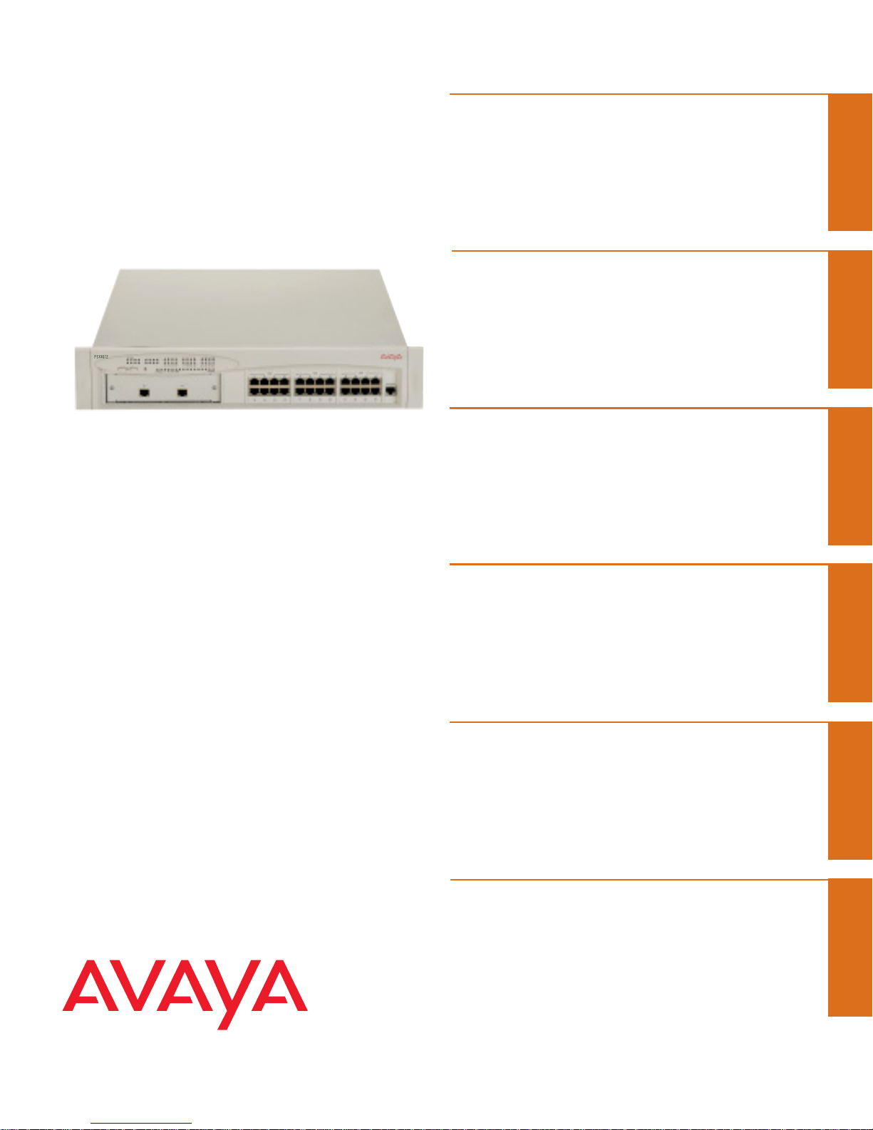
Avaya P133GT2
Quick Start Guide
Unpack
Rack mount (optional)
Connect the cables
Configure
Run Web-based
Manager (optional)
Power up
1
2
3
4
5
6

Unpack
Check the package contents for the following:
If any items are missing or damaged, contact your supplier.
Equipment
• One Avaya P130 Workgroup Switch
• One AC power cable
• One RJ-45 to DB-9 serial adapter cable
• Four rubber feet
• Four screws with washers for rack mounting
Ethernet connection cables are not supplied
Documentation
• Avaya P133GT2 Quick Start Guide (this document)
• Avaya P130 Release Notes
• Avaya P130 Documentation and Utilities CD (see detail below)
• Avaya Warranty and License Agreement
Avaya P130 Documentation and Utilities CD
The CD contains the latest Technical Documentation for the Avaya P130 Workgroup switches
and files for use with the Embedded Web Manager.
Technical Documentation
You can view and print the Technical Documentation using Adobe® Acrobat® Reader.
• Avaya P130 User ’s Guide
• Avaya P130 Device Manager User ’s Guide
Auxiliary Files for use with the Embedded Web Manager
Please refer to the documentation for information on how to use these files.
• Java plug-in
• Help files
Adobe Acrobat Reader
Use this application to view and print the User's Guides on this CD.
1
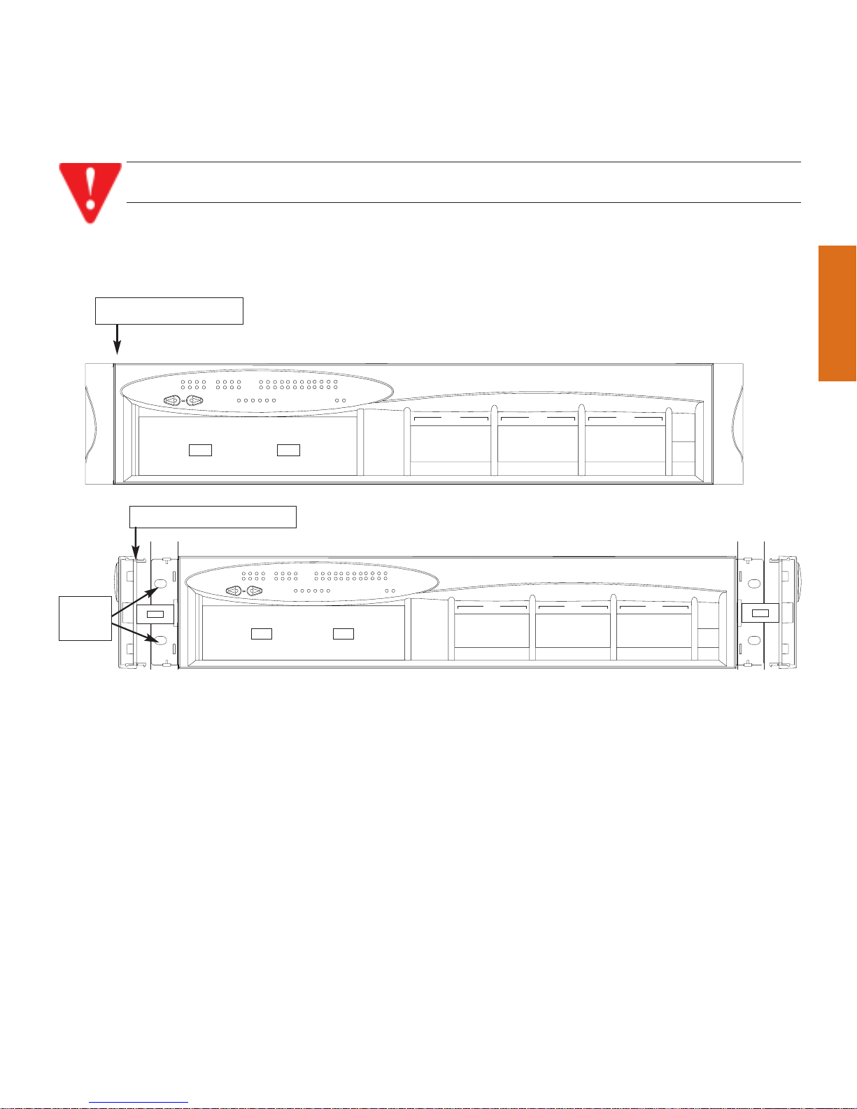
Rack mount (optional)
1. Snap open the hinged ends of the unit’s front panel to reveal the screw holes.
2. Position the unit in the rack.
3. Secure the unit to the rack, taking care not to overtighten the screws.
4. Snap closed the hinged ends of the front panel.
You can now safely connect the cables to the unit.
2
WARNING: Disconnect all cables from the unit before proceeding with the rack
installation.
13 14 15 16 17
1
LAG
234 5
CONSOLE
2118 19 20 2322 24
96
LAG
7
8
1110
LAG
12
P133GT2
51
FDX
15
52
COLLNK Tx Rx
1132
3
14
8
20
5
17
100
4
16
6
18
7
19
10229
21
OPR PWR
23
11
12
24
P133GT2
51
FDX
15
52
COLLNK Tx Rx
1132
3
14
8
20
5
17
100
4
16
6
18
7
19
10229
21
OPR PWR
23
11
12
24
13 14 15 16 17
1
LAG
234 5
CONSOLE
2118 19 20 2322 24
96
LAG
7
8
1110
LAG
12
Closed hinged end
Open hinged end
Screw
holes
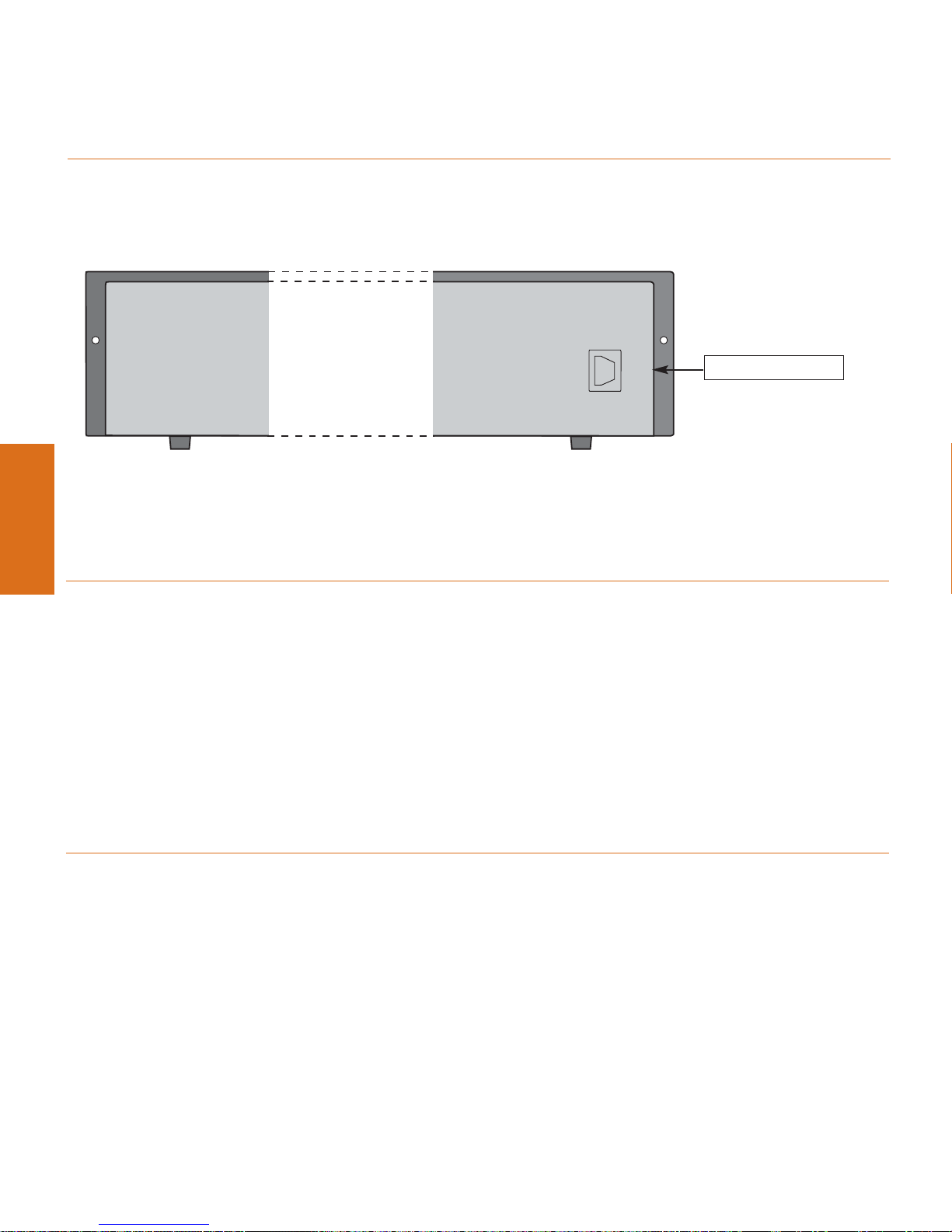
Power up
Avaya P130
1. Insert the power cord into the Power Supply connector on the rear of the unit.
2. Insert the other end of the power cord into the electricity supply.
The unit powers up and performs a self test procedure. The OPR AND PWR LEDs are
on after the self-test procedure is completed successfully.
Connect the cables
Connect PCs, servers, routers, workstations, and hubs
1. Connect the Ethernet connection cable (not supplied) to a 10/100 Mbps port on the front
panel of the P130.
You should use standard RJ-45 connections. You must use CAT-5 cable for 100 Mbps
operation.
2. Connect the other end of the cable to the Ethernet port of the PC, server, router, workstation, switch or hub.
Use a cross cable when connecting the P130 to a switch or hub.
3. Check that the appropriate link (LNK) LEDs light up.
Connect the console cable
1. Configure the serial port settings of the PC or terminal as follows: Baud Rate – 9600, Parity
– no, Data bits – 8, Stop bits – 1, Flow control – no.
2. Connect the supplied special RJ-45 connector to the port marked “Console” on the front
panel of the P130.
3. Connect the other end of the cable to a terminal or PC with terminal emulation software
installed.
3
Power Supply
Connector
AC connector
 Loading...