

Page 1

Avaya
User’s Guide
AVAYA P130
WORKGROUP SWITCH
SOFTWARE VERSION 2.9
July 2002
Page 2

Page 3

Contents
List of Figures .................................................................................................... ix
List of Tables...................................................................................................... xi
Chapter 1 Overview............................................................................................................. 1
P130 Family Features......................................................................................... 1
P130 Features...................................................................................................... 2
Auto-Negotiation ....................................................................................2
Link Aggregation Group (LAG) ...........................................................2
VLANs ......................................................................................................3
Multiple VLANs per Port ...........................................................3
QoS and Priority Support ......................................................................3
LAG and Link (Port) Redundancy .......................................................4
Spanning Tree .........................................................................................4
Congestion Control ................................................................................4
Advanced Congestion Control (Broadcast storm control) .... 4
IP Multicast Filtering (IGMP Snooping) .............................................4
Port Mirroring .........................................................................................5
Switch Configuration File ......................................................................5
Software Download ................................................................................ 5
P130 Network Management............................................................................. 6
P130 Device Manager (Embedded Web) ............................................. 6
P130 Command Line Interface (CLI) ................................................... 6
MultiService Network Manager™ .......................................................6
Avaya P130 Network Monitoring ................................................................... 7
RMON MIBs - RFC 1757 ........................................................................ 7
SMON MIBs - RFC 2613 ........................................................................7
Port Mirroring .........................................................................................7
SMON ....................................................................................................... 7
Avaya P130 Standards Supported................................................................... 9
IEEE ...............................................................................................9
IETF ...............................................................................................9
Chapter 2 P130 Front and Back Panels............................................................................ 11
Front Panel LEDs ............................................................................................. 11
Front Panel LEDs ..................................................................................12
Avaya P130 Back Panel ................................................................................... 13
BUPS Input Connector .........................................................................13
P130 User’s Guide i
Page 4

Contents
Chapter 3 Applications ...................................................................................................... 15
Typical Applications........................................................................................ 15
Chapter 4 Installation and Setup...................................................................................... 17
Setting up the Module ..................................................................................... 17
Front-Panel Pushbuttons .....................................................................19
Configuration Symbol ..........................................................................19
Serial Number ........................................................................................19
Power Supply ........................................................................................19
P130/P330/P120 Back-up Power Supply (BUPS) ............................19
Modem/RS-232 .....................................................................................20
Positioning......................................................................................................... 21
Rack Mounting ................................................................................................. 22
Connecting Cascaded Switches...................................................................... 23
To connect cascaded switches .............................................................23
Powering On – P130 Module AC................................................................... 24
Configuring the Switch ................................................................................... 24
Avaya P130 Default Settings........................................................................... 25
Switch Settings ......................................................................................25
Port Settings ...........................................................................................26
Connecting the Console Cable ............................................................27
Configuring the Terminal Serial Port Parameters ............................27
Connecting a Modem to the Console Port ........................................27
Assigning P130’s IP Stack Address ....................................................28
License Key Activation.................................................................................... 29
Enabling a Feature ................................................................................29
Chapter 5 Avaya P130 CLI - Architecture, Access &Conventions.............................. 31
CLI Architecture............................................................................................... 31
Establishing a Serial Connection.................................................................... 31
Establishing a Telnet Connection................................................................... 32
Entering the CLI ....................................................................................32
Conventions Used ............................................................................................ 32
Navigation, Cursor Movement and Shortcuts............................................. 34
Getting Help...................................................................................................... 34
Command Syntax............................................................................................. 34
Command Abbreviations ....................................................................34
Universal Commands...................................................................................... 35
Top and Up commands ........................................................................35
Retstatus command ..............................................................................35
Tree command .......................................................................................35
Chapter 6 Avaya P130 CLI ................................................................................................ 37
Command Groups............................................................................................ 37
General Commands ......................................................................................... 38
ii P130 User’s Guide
Page 5

Contents
Terminal Commands ...........................................................................38
Clear screen Command ........................................................................38
Ping Command .....................................................................................38
Tree Command ..................................................................................... 39
Access Level Commands ................................................................................ 39
User Level ..............................................................................................39
Privileged Level ....................................................................................40
Supervisor Level ................................................................................... 40
Exit Command ......................................................................................40
Tech Command .....................................................................................40
Account Modification Commands ................................................................ 41
Username Command ........................................................................... 41
No Username Command .....................................................................42
Show Username Command ................................................................42
License Commands.......................................................................................... 43
Multilayer Policy Licensing ................................................................43
Show License Command ..................................................................... 43
Set License Command ..........................................................................43
Time-related Commands ................................................................................ 44
Show time Command ..........................................................................44
Get time Command ..............................................................................44
Show timezone Command ..................................................................44
Set timezone Command .......................................................................45
Clear timezone Command ..................................................................45
Set time protocol Command ...............................................................45
Set time client Command ....................................................................45
Set time server Command ................................................................... 46
Show time parameters Command ..................................................... 46
System Status Commands .............................................................................. 47
Show system Command ......................................................................47
Set system location Command ........................................................... 47
Set system name Command ................................................................ 48
Set system contact Command .............................................................48
Show image version Command .........................................................48
Show interface Command ...................................................................49
Set interface Command ........................................................................49
Show log Command .............................................................................49
Clear log Command .............................................................................50
Show module Command .....................................................................51
Show module-identity Command .....................................................51
Show module-config Command ........................................................52
Show keep alive Command ................................................................53
Show timeout Command .................................................................... 53
Set logout Command ...........................................................................53
P130 User’s Guide iii
Page 6

Contents
Retstatus Command .............................................................................54
Hostname Command ...........................................................................54
Show running-config Command ........................................................55
Show startup-config Command ..........................................................55
Show stack-config Command .............................................................55
Download/Upload Commands..................................................................... 56
Dir Command ........................................................................................56
Show tftp download/upload status Command ...............................57
Show tftp download software status Command .............................58
Copy stack-config tftp Command ......................................................58
Copy module-config tftp Command ..................................................59
Copy tftp stack-config Command ......................................................59
Copy tftp module-config Command ..................................................60
Copy tftp EW_archive Command ......................................................60
Copy tftp SW_image Command .........................................................61
Copy tftp startup-config Command ...................................................61
Copy running-config tftp Command .................................................62
Copy startup-config tftp Command ...................................................62
Show web aux-files-url Command .....................................................62
Set web aux-files-url Command .........................................................63
Copy running-config startup-config Command ..............................63
Erase startup-config Command ..........................................................64
Show erase status Command ..............................................................64
Reset Commands.............................................................................................. 65
Reset Command ....................................................................................65
Nvram initialize Command .................................................................65
Port Commands................................................................................................ 66
Show port Command ...........................................................................66
Show port flowcontrol Command ......................................................67
Show port auto-negotiation-flowcontrol-advertisement
Command ...............................................................................................68
Show port trap Command ...................................................................68
Show port channel Command ............................................................69
Show port mirror Command ...............................................................70
Set port level Command ......................................................................70
Set port negotiation Command ...........................................................71
Set port enable Command ...................................................................72
Set port disable Command ..................................................................72
Set port speed Command ....................................................................73
Set port duplex Command ..................................................................73
Set port flowcontrol Command ..........................................................74
Set port auto-negotiation-flowcontrol-advertisement Command .75
Set port name Command .....................................................................76
Set port trap Command .......................................................................76
iv P130 User’s Guide
Page 7

Contents
Set port channel Command .................................................................77
Set port redundancy enable/disable Command .............................77
Set port redundancy Command ......................................................... 78
Show port redundancy Command ....................................................78
Set port mirror Command ................................................................... 79
Clear port mirror Command ...............................................................79
Set port vlan Command .......................................................................79
FlowControl Commands ................................................................................ 81
Set internal buffering Command ........................................................81
Show internal buffering Command ...................................................81
Set port flowcontrol Command ..........................................................81
Show port flowcontrol Command .....................................................81
Spanning Tree Commands ............................................................................. 82
Show spantree Command ...................................................................82
Set spantree Commands ...................................................................... 84
Set spantree priority Command .........................................................84
Set port spantree Command ...............................................................84
Set port spantree priority Command .................................................85
Set port spantree cost Command .......................................................85
CAM Commands ............................................................................................. 86
Clear cam Command ...........................................................................86
Show cam Commands ......................................................................... 86
VLAN Commands ........................................................................................... 87
Show trunk Command ........................................................................87
Set trunk Command .............................................................................88
Clear vlan Command ...........................................................................88
Set inband vlan Command .................................................................. 89
Show vlan Command ........................................................................... 89
Set vlan Command ...............................................................................90
Set port vlan Command .......................................................................90
Set port vlan-binding-mode Command ............................................ 91
Show port vlan-binding-mode Command .......................................91
Set port static-vlan Command ............................................................92
Clear port static-vlan Command ........................................................ 92
Congestion Control Commands .................................................................... 93
Show broadcast storm control Command ........................................93
Set broadcast storm control Command .............................................93
Set broadcast storm control threshold Command ........................... 94
Multicast Commands ...................................................................................... 95
Show intelligent-multicast Command ...............................................95
Set intelligent-multicast Command ................................................... 95
Set intelligent-multicast client-port-pruning time Command .......95
Set intelligent-multicast router-port-pruning time Command ...... 96
Set intelligent-multicast group-filtering-delay time Command .... 96
P130 User’s Guide v
Page 8

Contents
IP Route Configuration Commands.............................................................. 97
Show ip route Command .....................................................................97
Set ip route Command .........................................................................97
Clear ip route Command .....................................................................98
PPP Commands................................................................................................ 99
Show ppp session command ...............................................................99
Set interface ppp command ...............................................................100
Set interface ppp enable | enable-always | disable | off | reset
Command .............................................................................................100
Show ppp authentication Command ...............................................101
Set ppp authentication incoming Command ..................................101
Set ppp chap-secret Command .........................................................102
Show ppp incoming timeout Command .........................................102
Set ppp incoming timeout Command ..............................................103
Show ppp configuration Command ................................................103
Show ppp baud-rate Command .......................................................104
Set ppp baud-rate Command ............................................................104
Radius Commands......................................................................................... 105
Show radius authentication Command ...........................................105
Set radius authentication Command ...............................................105
Set radius authentication secret Command ....................................105
Set radius authentication server Command ...................................106
Clear radius authentication server Command ...............................106
Set radius authentication retry-time Command .............................106
Set radius authentication retry-number Command .......................107
Set radius authentication udp-port Command ..............................107
RMON Commands ........................................................................................ 108
No rmon history Command ..............................................................108
No rmon alarm Command ................................................................108
No rmon event Command .................................................................108
Rmon alarm Command ......................................................................108
Rmon event Command ......................................................................109
Rmon history Command ...................................................................110
Show rmon history Command ..........................................................110
Show rmon alarm Command ............................................................111
Show rmon event Command ............................................................111
Show rmon statistics Command .......................................................112
SNMP Commands.......................................................................................... 113
Show snmp Command .......................................................................113
Show snmp retries Command ...........................................................113
Show snmp timeout Command ........................................................114
Set snmp community Command ......................................................114
Set snmp retries Command ...............................................................115
Set snmp timeout Command ............................................................115
vi P130 User’s Guide
Page 9

Contents
Set snmp trap auth Command ..........................................................115
Set snmp trap Commands .................................................................116
Clear snmp trap Command .............................................................. 117
Policy Networking......................................................................................... 118
Policy Rules and Filters .....................................................................118
Using Policy Lists .................................................................... 118
Policy-based Networking Commands........................................................ 119
Show access-group Command ......................................................... 119
Show ip access-lists Command ........................................................119
Show dscp Command ........................................................................120
ip access-group Command .............................................................120
ip access-list Command .....................................................................121
ip access-list-copy Command ...........................................................122
ip access-default-action Command ..................................................122
ip access-list-name Command ..........................................................123
ip access-list-owner Command ........................................................123
ip access-list-cookie Command ........................................................123
Validate-group Command ................................................................124
Set qos policy-source Command ......................................................124
Set qos dscp-cos-map Command .....................................................125
Set qos dscp-name Command .......................................................... 125
Set qos trust Command ..................................................................... 126
IP port range upper limit for Command .........................................126
Appendix A Avaya P130 Embedded Web Manager ....................................................... 127
System Requirements.................................................................................... 127
Running the Embedded Manager ............................................................... 128
Installing the Java Plug-in............................................................................. 130
Installing from the Avaya P130 Documentation and
Utilities CD .......................................................................................... 130
Install from the Avaya Site ................................................................130
Install from your Local Web Site ......................................................130
Installing the On-Line Help and Java Plug-In on your Web Site............ 131
Documentation............................................................................................... 131
Software Download....................................................................................... 131
Appendix B Specifications .................................................................................................. 133
Avaya P130 Switches..................................................................................... 133
Physical ................................................................................................133
Power Requirements – AC ................................................................133
Environmental .....................................................................................133
Interfaces ..............................................................................................134
Basic MTBF ..........................................................................................134
Safety ....................................................................................................134
EMC Emissions ...................................................................................135
P130 User’s Guide vii
Page 10

Contents
Emissions ..................................................................................135
Immunity ..................................................................................135
Avaya Approved SFF/SFP GBIC Transceivers ......................................... 135
Safety Information ..............................................................................135
Laser Classification ..................................................................135
Usage Restriction .....................................................................136
Installation ...........................................................................................136
Installing and Removing a SFF/SFP GBIC Transceiver ....136
Specifications .......................................................................................137
LX Transceiver .........................................................................137
SX Transceiver ..........................................................................137
Agency Approval ................................................................................137
Connector Pin Assignments ......................................................................... 138
Console Communications ..................................................................138
Appendix C Index of all CLI Commands.......................................................................... 139
CLI Command Set.......................................................................................... 139
Appendix D How to Contact Us......................................................................................... 143
In the United States .............................................................................143
In the EMEA (Europe, Middle East and Africa) Region ...............143
In the AP (Asia Pacific) Region .........................................................145
In the CALA (Caribbean and Latin America) Region ...................145
viii P130 User’s Guide
Page 11

List of Figures
Figure 2.1 P133T Front Panel LEDs and Switches ...................................11
Figure 2.2 P133F2/G2/GT2 Front Panel LEDs and Switches ................ 11
Figure 2.3 P134 Front Panel LEDs and Switches......................................12
Figure 2.4 P133G2/P134G2 AC Back Panels ............................................ 13
Figure 3.1 The Avaya P130 in a Network.................................................. 15
Figure 4.1 Avaya P133T Module ................................................................17
Figure 4.2 Avaya P133F2 Module............................................................... 18
Figure 4.3 Avaya P133G2 Module.............................................................. 18
Figure 4.4 Avaya P134G2 Module.............................................................. 18
Figure 4.5 Avaya P133GT2 Module ...........................................................19
Figure 4.6 Avaya P130 Rack Mounting ....................................................22
Figure 4.7 Correct Cable Connection .........................................................23
Figure 4.8 Incorrect Cable Connection ......................................................24
Figure A.1 The Welcome Page...................................................................128
Figure A.2 Web-based Manager ................................................................129
Figure A.3 Options for Installing the Java Plug-in..................................129
P130 User’s Guide ix
Page 12

List of Figures
x P130 User’s Guide
Page 13

List of Tables
Table 2.1 LED Indications ..........................................................................12
Table 4.1 Default Switch Settings ............................................................. 25
Table 4.2 Default Port Settings ..................................................................26
Table 5.1 Navigation, Cursor Movement and Shortcuts....................... 34
Table B.1 Pinout of the Required Connection for Console
Communications ......................................................................138
P130 User’s Guide xi
Page 14

List of Tables
xii P130 User’s Guide
Page 15

Chapter 1
Overview
P130 Family Features
The P130 family is a line of easy-to-use, cost-effective workgroup
10/100M switches which allow you to build smart network edge/small workgroup
solutions.
The P130 line includes the following fixed-configuration Layer-2/Multilayer Policy
workgroup switches:
• P133T – twenty-four 10/100BaseTX ports.
• P133F2 – twenty-four, 10/100BaseTX and two 100BaseFX ports.
• P133G2 – twenty-four, 10/100BaseTX and two GBIC SFP (Small Form
Pluggable) ports.
• P134G2 – fourty-eight, 10/100BaseTX and two GBIC SFP ports.
• P133GT2 – twenty-four, 10/100BaseTX and two 100/1000BaseT ports.
The P130 switches have the following features:
— Auto-Negotiation
— Link Aggregation Groups (LAG)
— 802.1Q VLAN
— QoS and Priority Support
— LAG and Link (Port) Redundancy
— Spanning Tree
— Congestion Control
— IP Multicast Filtering (IGMP Snooping)
— Port Mirroring
— Switch Configuration File
— Software Download
— Three options for Network Management
• The P130 uses Multilayer Policy technology to provide advanced policy-based
networking (with the purchase of an Multilayer Policy License). The policies are
used to enforce the Quality of Service (QoS) of IP packets, which are sent by
locally attached stations.
• You can cascade up to four P133G2 and P134G2 modules using the Avaya
X130CK kit which includes low- cost integrated SFP transceivers and a 2 m
cascading cable. The X130CK provides up to 2 Gbps traffic throughput between
the modules.
Avaya P130 User’s Guide 1
Page 16

Chapter 1 Overview
Avaya P130 Management includes:
• CLI (same CLI as the other Cajun Campus products).
— Connection via RS-232, Telnet, Modem and PPP.
— Telnet Passwords and Embedded Radius Client.
• P130 Web-based Management
• MultiService Network Manager supports the P130 management.
•Upload/Download
— Configuration file (in CLI format)
— Software Image file (single Bank) – download only
— Embedded Web file (download only)
— Log file (upload only).
P130 Features
The standard P130 features of the switch are described below.
Auto-Negotiation
Every 10/100 port on the P130 supports Auto-Negotiation which automatically
detects and supports the duplex mode and speed of a connected device. Autonegotiation is also supported on the Gigabit Ethernet ports for flow control mode
only.
This means that you can simply connect the P130 to Ethernet or Fast Ethernet
equipment at full or half duplex without configuration.
Link Aggregation Group (LAG)
LAG provides increased bandwidth and redundancy for critical high-bandwidth
applications such as inter-switch links and connections to servers. You can
aggregate the bandwidth of up to eight 10/100Base-Tx or two 1000Base-X ports.
Load sharing ensures that if one of the port connections fails, the other connections
will assume the load seamlessly. Load balancing guarantees that the traffic load at
any level will be divided among all the LAG links (see also the LAG documentation
module).
LAGs can be created in the switch in order to increase bandwidth and resiliency in
switch-to-switch and server-to-switch connections. P133T supports up to 3 LAGs,
P133G2, P133GT2 and P133F2 support up to 4 LAGs, P134G2 supports up to 6
LAGs.
Each LAG is considered a single switch interface. Packets are not forwarded
between its ports, and non-unicast packets are transmitted only through one port the "Flood"(or "Base") port. In addition, packet order is maintained within each
session.
2 Avaya P130 User’s Guide
Page 17

VLANs
Chapter 1 Overview
The packets are distributed between ports in a LAG according to Source-MAC &
Destination-MAC addresses. Three Least Significant Bits (LSB) of MAC source
address are logically XOR-ed with 3 LSBs of MAC Destination Address. This
scheme ensures enhanced load balancing of the traffic, sent out through the LAG
ports.
You can manually configure a LAG using the CLI or a Management application.
When initially created, the LAG will inherit all parameters from the Base (the 1st
configured) port. These include Admin State (enable/disable), VLAN ID, Tagging
Mode, Priority Level, STA Enable/Disable, Auto-Neg, Flow Control, Duplex and
Speed. Each parameter change of the LAG interface will change this parameter in all
ports in the LAG.
If a link has failed, traffic distribution continues on other ports in the LAG. The port
is still configured as a member in the LAG and resumes operation in case of link up.
If you manually remove the port from the LAG, the port will automatically become
disabled. You can then change any of the port’s configuration parameters.
To set up a LAG or show an existing LAG configuration see the set/show
channel commands in the CLI Chapter.
The P130 suports 62 VLANs out of 4K tagged /untagged VLANs [1…4079]. All
VLANs are fully IEEE 802.1Q compliant (VLANs [4080…4095] reserved for internal
use).
The P130 has Standard VLAN MIB support.
Multiple VLANs per Port
The P130 provides the ability to set multiple VLANs per port. The two available
Port Multi-VLAN binding modes are:
• Bound to Configured - the port supports all the VLANs configured in the
switch/stack. These may be either Port VLAN IDs (PVID) or VLANs that were
manually added to the switch.
• Statically Bound - the port supports VLANs manually configured on it.
QoS and Priority Support
The P130 supports end-to-end QoS and provides the following tools:
• Queuing - Four egress queues per port
• Port Priority - Transparent IEEE 802.1p and per port basis
• Scheduling - Weighted Round Robin
Avaya P130 User’s Guide 3
Page 18

Chapter 1 Overview
LAG and Link (Port) Redundancy
Redundancy can be implemented between any two ports in a switch. You can also
assign redundancy between any two LAGs in the switch or between a LAG and a
port.
Spanning Tree
The P130 implements the IEEE 802.1D Spanning Tree (STP) algorithm in order to
allow backup paths and prevent loops throughout the Physical LAN. Spanning Tree
is not available when redundant links are defined.
The P130 supports Spanning Tree per port as well as Spanning Tree per module, as
may be required on the network.
Note: You cannot configure both Port Redundancy and Spanning Tree on an
individual P130 switch.
Congestion Control
Congestion control is a key element of maintaining network efficiency as it prevents
resource overload.
The P130 supports congestion control on all Ethernet ports, using the following:
• Head Of Line (HOL) Blocking Prevention
• IEEE 802.3x Flow Control in full duplex mode.
Advanced Congestion Control (Broadcast storm control)
Limits broadcast, multicast, and unknown packet traffic that traverses the switch.
IP Multicast Filtering (IGMP Snooping)
The IP Multicast Filtering uses the IGMP Snooping protocol to send a single copy of
an IP packet to multiple destinations, and can be used for various applications
including video streaming and video conferencing. This protocol reduces network
congestion and allows more efficient switching of IP multicast traffic (see also the IP
Multicast documentation module).
On Local Area Networks (LANs), IP Multicast packets are transmitted in MAC
Multicast frames. Traditional LAN switches flood these Multicast packets to all
stations in the VLAN. Multicast filtering functions may be added to the Layer 2
switches to avoid sending Multicast packets where they are not required. Layer 2
switches capable of Multicast filtering send the Multicast packets only to ports that
connect members of that Multicast group. This is typically based on IGMP.
4 Avaya P130 User’s Guide
Page 19

Port Mirroring
The P130 has a built-in ”mirroring” capability, that allows forwarding of all the
traffic to/from specific ”copy source” to a ”copy destination” (also called a probeport or sniffer-port), excluding errors and frames with errors.
When you require detailed information about the traffic at a particular port, rather
than attaching an expensive analyzer to each port (or moving such a probe from
port to port), the network administrator may attach an external probe to any P130
port defined as a destination port and analyze any switched port by mirroring its
Rx/Tx or Tx only traffic to that destination port.
Note: Port Mirroring must be configured individually for each P130 switch.
Switch Configuration File
The Configuration File feature allows the user to read the P130 configuration
parameters and save them to a file on the station. The switch configuration
commands in the file are in CLI format. The user can edit the file (if required) and
re-configure the P130 by downloading the configuration file. Although the file can
be edited, it is recommended to keep changes to the file to a minimum.
TVisability™ MultiService Network Manager Software Update Manager
(CajunView™ UpdateMaster)
and/or the CLI.
Chapter 1 Overview
Software Download
Safe S/W download procedure – backup code always present.
Avaya P130 User’s Guide 5
Page 20

Chapter 1 Overview
P130 Network Management
Comprehensive network management as a key component of today’s networks.
Therefore we have provided multiple ways of managing the P130 to suit your
needs.
P130 Device Manager (Embedded Web)
The built-in P130 Device Manager (Embedded Web Manager) allows you to manage
a P130 switch using a Web browser without purchasing additional software. This
application works with the Microsoft® Internet Explorer and Netscape® Navigator
web browsers and Sun Microsystems Java™ Plug-in.
P130 Command Line Interface (CLI)
The P130 CLI provides a terminal type configuration tool for local or remote
configuration of P130 features and functions.
MultiService Network Manager™
When you need extra control and monitoring or wish to manage other Cajun
Campus equipment, then the Visability™ MultiService Network Manager suite is
the answer. This suite provides the ease-of-use and features necessary for optimal
network utilization.
• Visability™ MultiService Network Manager Software operates under HP
OpenView, for Windows® 2000/NT® or Solaris.
• Visability™ MultiService Network Manager Software operates in standalone
mode for Windows® 2000/NT®.
6 Avaya P130 User’s Guide
Page 21

Avaya P130 Network Monitoring
RMON MIBs - RFC 1757
• RMON support for groups 1,2,3 and 9:
—Statistics
—History
—Alarms
—Events
SMON MIBs - RFC 2613
• SMON support for groups:
— Data Source Capabilities
—Port Copy
— VLAN and Priority Statistics
Port Mirroring
The Avaya P130 provides port mirroring for additional network monitoring
functionality. You can filter the traffic and mirror either outgoing traffic from the
source port or both incoming and outgoing traffic. This allows you to monitor the
network traffic you need.
Chapter 1 Overview
SMON
The P130 supports Avaya’s ground-breaking SMON Switched Network
Monitoring, which the IETF has now adopted as a standard (RFC2613). SMON
provides an unprecedented top-down monitoring of switched network traffic at the
following levels:
• Enterprise Monitoring
• Switch Monitoring
• VLAN Monitoring
• Port-level Monitoring
This top-down approach gives you rapid troubleshooting and performance
trending to keep the network running optimally.
Note: Visability™ MultiService Network Manager Software is required to run
SMON monitoring.
Avaya P130 User’s Guide 7
Page 22

Chapter 1 Overview
Note: You need to purchase one SMON License per Avaya P130 stack.
8 Avaya P130 User’s Guide
Page 23

Avaya P130 Standards Supported
The P130 complies with:
IEEE
• 802.3x Flow Control on all ports
• 802.1Q VLAN and Priority Tagging
• 802.1D Bridges and STA
• 802.3 Ethernet ports
• 802.3u Fast Ethernet ports
• 802.3z Gigabit Ethernet ports
• 802.3ab Gigabit over Copper (1000 BaseT)
IETF
• MIB-II - RFC 1213
• Bridge MIB for Spanning Tree - RFC 1493
• Time Protocol - RFC 0868
• SNMPv1 - RFC 1157
• PPP Internet Protocol Control Protocol (IPCP) - RFC 1332
• PPP Authentication Protocols (PAP & CHAP) - RFC 1334
• PPP - RFC 1661
• RMON support for groups 1,2 3, and 9 - RFC 1757
• SNTP - RFC-1769
• SMON - RFC 2613
• VLAN extension to Bridge MIB, Relevant MIB objects: dot1q (dot1qBase,
dot1qVlanCurrent).
Chapter 1 Overview
Avaya P130 User’s Guide 9
Page 24

Chapter 1 Overview
10 Avaya P130 User’s Guide
Page 25
Chapter 2
Switches
Switches
P130 Front and Back Panels
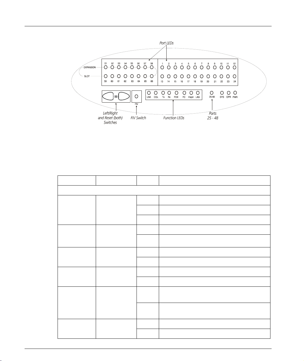
Front Panel LEDs
The front panel LEDs consist of Port LEDs and Function LEDs. The Port LEDs
display information for each port according to the illuminated function LED. The
function is selected by pressing the left or right button until the desired parameter
LED is illuminated.
For example, if the COL LED is illuminated, then all Port LEDs show the collision
status of their respective port. If you wish to select Rx then press the left button
several times until the Rx function LED lights.
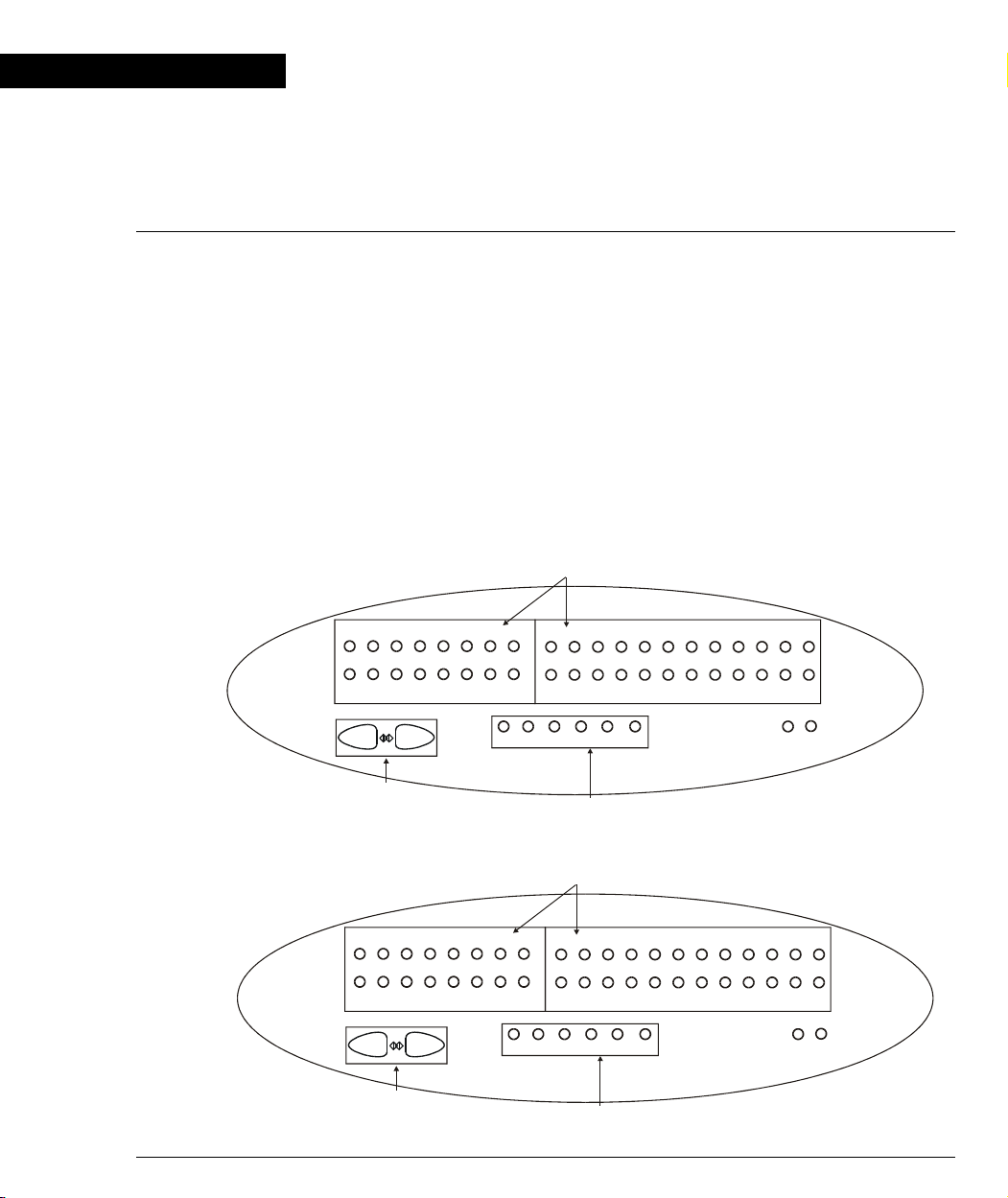
Figure 2.1 shows the P133T front panel and Figure 2.2 shows the P133F2/G2 front
panel with a detailed view of the LEDs (described in Table 2.1) and pushbuttons.
The RJ-45 console connector is at the bottom right.
Figure 2.1 P133T Front Panel LEDs and Switches
Port LEDs
7
9
8
10 11 12
22 23 24
21
OPR
PWR
Left/Right
and Reset (both)
12
14 15 16
13
LNK COL Tx FDXRx
Function LEDs
3456
17
100
18 19 20
Figure 2.2 P133F2/G2/GT2 Front Panel LEDs and Switches
Port LEDs
51
52
Left/Right
and Reset (both)
LNK COL Tx FDXRx
12
14 15 16
13
Function LEDs
3456
100
Avaya P130 User’s Guide 11
17
7
18 19 20
9
8
10 11 12
22 23 24
21
OPR
PWR
Page 26
Chapter 2 P130 Front and Back Panels
Figure 2.3 P134 Front Panel LEDs and Switches
Front Panel LEDs
Following is a Table describing P130 front panel LEDS, and the meaning of the ON,
OFF and Blink (where applicable) LED status:
Table 2.1 LED Indications
LED Function State Meaning
Module/Function-level
On Power is up.
PWR Power Status
CPU
OPR
LNK Link Status
COL Collision
25-48(*)
Tx (**) Tx traffic
12 Avaya P130 User’s Guide
Operational
Status
Port Display
Mode
Off Power is down.
Blink BUPS is activated and main power is down
On CPU Boot and BIT operations completed
Off CPU is in Boot or BIT operation
On Link OK
Off No Link
On Collision occurred on line
Off There is no collision
Off Ports 1-24 are displayed in the Port LEDs, if
selected
On Ports 25-48 are displayed in the Port LEDs, if
selected
On Packets transmission on this port
Off No activity on port
Page 27
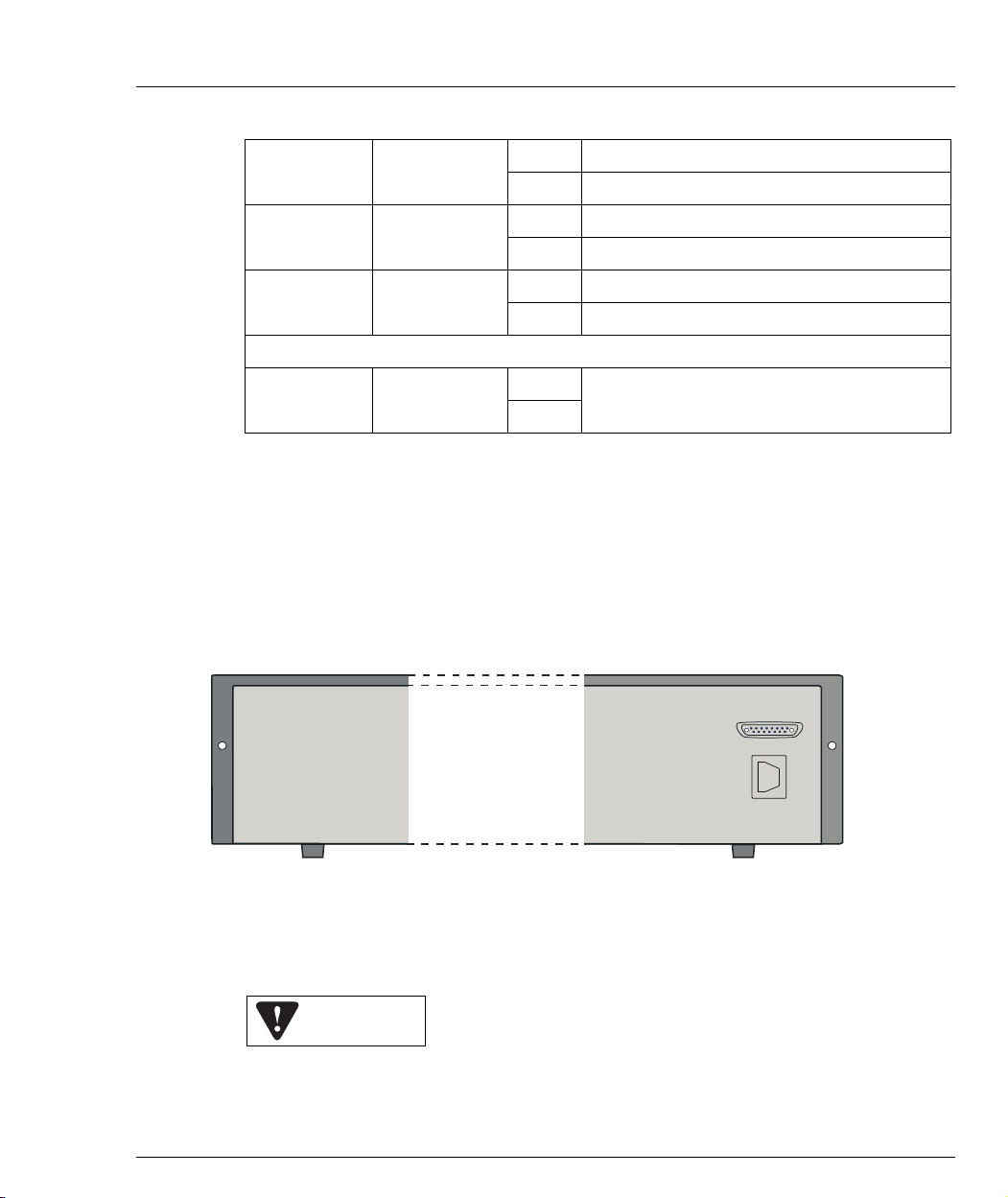
Table 2.1 LED Indications
Chapter 2 P130 Front and Back Panels
Rx (**) Rx traffic
FDX
100M 100M Speed
Port-level
1...24
,51,52
(*) This LED exists only in the P134G2
(**) Not activated for SFP Giga ports.
Full Duplex
Mode
LED per port
Avaya P130 Back Panel
The Avaya P133G2 and P134G2 back panels have Power Supply and BUPS
connectors. Figure 2.4 shows the back panel of these switches.
Figure 2.4 P133G2/P134G2 AC Back Panels
On Packets received on this port
Off No activity on port
On Port in Full Duplex mode
Off Port in Half Duplex mode
On Port is working in 100M
Off Port is working in 10M or 1000M (Gig port)
On
Off
According to the function that was selected
from the function-level LEDs described above
BUPS
Connector
Power Supply
Connector
BUPS Input Connector
The BUPS input connector (see Figure 2.4) is a 5 V DC connector for use with the
P130 BUPS unit only.
BUPS Input
Avaya P130 User’s Guide 13
Page 28

Chapter 2 P130 Front and Back Panels
14 Avaya P130 User’s Guide
Page 29
Chapter 3
y
Applications
Typical Applications
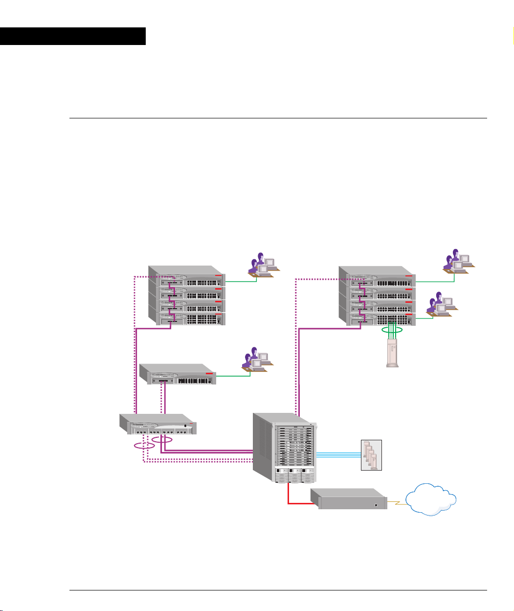
The Avaya P130 is a low cost workgroup switch that is connected at the edge of the
LAN. It connects end-users and servers and forwards their traffic into the core of the
network.
As shown in the application below, P130 can be connected at the edge of a LAN, or
stacked in a group. The P130 can be connected to the backbone or to the distribution
switch using a LAG or single link connections, that can support LAG or link
redundancy.
Figure 3.1 The Avaya P130 in a Network
Avaya P130
Avaya P130
10/100 Mbps Ethernet
10/100 Mbps Ethernet
Avaya P332G-ML
GBIC Ethernet
with LAG and
Redundancy
Avaya P882
AvayaP880
Avaya P130
GBIC Ethernet
with Redundancy
Server Farm
100 Mbps
Fiber
Ethernet
Ava
a WAN Access
10/100 Mbps Ethernet
10/100 Mbps Ethernet
4 x 100 Mbps
Ethernet LAG
Internet
Avaya P130 User’s Guide 15
Page 30

Chapter 3 Applications
16 Avaya P130 User’s Guide
Page 31

Chapter 4
Installation and Setup
The Avaya P130 is ready to work after you carry out the installation instructions
given below. All the P130 ports provide complete connectivity and no configuration
is required to make the system work.
Setting up the Module
The P130 front panel contains LEDs, controls, 10/100BaseTX ports and a console
connector. The status LEDs and control buttons provide at-a-glance module status
information.
The P130 allows you to make the following network connections from the ports on
the front panel:
• The P133G2 and P134G2 modules have two SFP (3.3 V-powered) ports for plugin 1000BASE-SX or LX SFP GBIC Transceivers. Alternatively, you can cascade
up to four P130 modules via a 2-m long Avaya X130CK cable. This proprietary
low-cost cable has built-in connectors which fit directly into the SFP slot. The
cable provides up to 2Gbps traffic throughput between modules.
• P133F2 has two fixed 100BASE-FX SC ports.
• P133GT2 has two fixed 100/1000BASE-T RJ-45 ports.
• P133T has no uplink ports.
Figure 4.1 Avaya P133T Module
Avaya P130 User’s Guide 17
Page 32

Chapter 4 Installation and Setup
Figure 4.2 Avaya P133F2 Module
Figure 4.3 Avaya P133G2 Module
Figure 4.4 Avaya P134G2 Module
18 Avaya P130 User’s Guide
Page 33

Figure 4.5 Avaya P133GT2 Module
Front-Panel Pushbuttons
Two pushbuttons, Left and Right, are used to select the function to be shown
simultaneously on all Port LEDs. The current function selected is indicated by a lit
Function LED.
When you press both Left and Right pushbuttons simultaneously for 1.5 seconds
then the module is reset. The LEDs are described on Page 12.
Configuration Symbol
The Configuration Symbol (C/S) of the P130 module is the hardware version
number and can be found either via the MultiService Network Manager application,
via the CLI, or on a label on the module.
Chapter 4 Installation and Setup
Serial Number
The P130 Serial Number is a unique number allocated to a specific P130 module.
This 7-digits number is shown on a label on the module and can be found using the
MIB item - genGroupSerialNumber.
Power Supply
The P130 110/220 VAC power inlet is at the back of the box.
P130/P330/P120 Back-up Power Supply (BUPS)
The P133G2 and P134G2 modules have a Back-Up Power Supply (Female D-Type
connector) connector on their back panels. You can use the same BUPS unit for the
P130, P330 and P120 switches.
The BUPS input is 150 W @ 5 V DC and operates in load power sharing mode with
the internal P130 module power supply (See: P133G2/P134G2 AC Back Panels on
Page 13).
Avaya P130 User’s Guide 19
Page 34

Chapter 4 Installation and Setup
Modem/RS-232
The console connector on the P130's front panel is for modem/RS-232 connections.
Whether the port functions as a Terminal or Modem port depends on the type of the
connected cable, which selects either mode.
Warning: Use only the supplied configuration cable with RJ45 to D9 Serial and RJ45
to 25-pin modem adapters. For the pinouts of the connectors see: Connector Pin
Assignments on Page 138.
20 Avaya P130 User’s Guide
Page 35

Positioning
Avaya P130 can be mounted alone or you can cascade several switches in a standard
19-inch equipment rack in a wiring closet or equipment room. Up to 4 units can be
cascaded in this way. When deciding where to position the unit, ensure that:
• It is accessible and cables can be connected easily and according to the
• Cabling is away from sources of electrical noise such as radio transmitters,
• Water or moisture cannot enter the case of the unit.
• Air-flow around the unit and through the vents in the back and sides of the case
Note: You must use low-cost proprietary X130CK cables to interconnect cascaded
switches.
Chapter 4 Installation and Setup
configuration rule.
broadcast amplifiers, power lines and fluorescent lighting fixtures.
is not restricted.
Avaya P130 User’s Guide 21
Page 36

Chapter 4 Installation and Setup
Rack Mounting
The P130 case fits in most standard 19-inch racks. P130 is 2U (88mm, 3.5”) high.
Place the P130 in the rack as follows:
1 Snap open the hinged ends of the front panel to reveal the fixing holes.
2 Insert the unit into the rack. Ensure that the four P130 screw holes are aligned
with the rack hole positions as shown in Figure 4.6.
Figure 4.6 Avaya P130 Rack Mounting
3 Secure the unit in the rack using the screws. Use two screws on each side. Do
not overtighten the screws.
4 Snap closed the hinged ends of the front panel.
5 Ensure that ventilation holes are not obstructed.
22 Avaya P130 User’s Guide
Page 37

Connecting Cascaded Switches
Note: The information in this section only applies to the P133G2 and P134G2.
Note: The two SFP transceivers on the ends of the cable are identical. Each SFP
transceiver can be connected to either an “Up“ or “Down“ port.
To connect cascaded switches
1 Plug one of the SFP transceivers into the port marked “52 Up” on the bottom
P130 switch.
2 Plug the other SFP transceiver into the port marked “51 Down” on the P130
switch above.
The connections are illustrated in Figure 4.7.
3 Repeat Steps 1 and 2 until you reach the topmost switch.
Caution: Do not cross connect two P130 switches with two cables.
Chapter 4 Installation and Setup
Note: You can cascade up to 4 P130 switches.
Figure 4.7 Correct Cable Connection
P130
51
52
11323148205
41661871910229
EXPANSION
SLOT
51
Down
P130
51 52
Down
51
52
EXPANSION
SLOT
COLLNK Tx Rx
COLLNK Tx Rx
51 52
Down
P130
51
52
EXPANSION
SLOT
COLLNK Tx Rx
51 52
Down
52
UP
P130
51
52
EXPANSION
SLOT
COLLNK Tx Rx
51 52
Down
Avaya P130 User’s Guide 23
15
FDX
11323148205
15
FDX
11323148205
15
FDX
11323148205
15
FDX
17
100
Up
41661871910229
17
100
Up
41661871910229
17
100
Up
41661871910229
17
100
Up
11 12
21
23
24
OPR PWR
11 12
21
23
24
OPR PWR
11 12
21
23
24
OPR PWR
11 12
21
23
24
OPR PWR
LAG
1
234 5
13 14 15 16 17
LAG
1
234 5
13 14 15 16 17
LAG
1
234 5
13 14 15 16 17
LAG
1
234 5
13 14 15 16 17
LAG
6
78 1110
LAG
78 1110
LAG
6
78 1110
LAG
78 1110
LAG
9
2118 19 20 2322 24
LAG
96
2118 19 20 2322 24
LAG
9
2118 19 20 2322 24
LAG
96
2118 19 20 2322 24
12
CONSOLE
12
CONSOLE
12
CONSOLE
12
CONSOLE
Page 38

Chapter 4 Installation and Setup
Figure 4.8 Incorrect Cable Connection
P130
51
52
1
23148205
EXPANSION
SLOT
P130
51
EXPANSION
SLOT
13
15
FDX
COLLNK Tx Rx
51 52
Down
52
11323148205
15
FDX
COLLNK Tx Rx
51 52
Down
41661871910229
17
100
Up
41661871910229
17
100
Up
21
21
Powering On – P130 Module AC
For the AC input version of the P130, insert the power cord into the power inlet in
the back of the unit. The unit powers up.
1 If you are using a BUPS, insert a power cord from the BUPS into the BUPS
connector in the back of the unit. The unit powers up.
2 After power up or reset, the P130 performs a self test procedure.
Configuring the Switch
11 12
23
24
OPR PWR
11 12
23
24
OPR PWR
LAG
1
234 5
13 14 15 16 17
LAG
1
234 5
13 14 15 16 17
LAG
78 1110
LAG
78 1110
LAG
96
2118 19 20 2322 24
LAG
96
2118 19 20 2322 24
12
CONSOLE
12
CONSOLE
The P130 may be configured using the text-based Command Line Interface (CLI)
utility, the built-in P130 Device Manager (Embedded Web) or MultiService
Network Manager.
For instructions on the text-based utility, see the CLI chapter.
For instructions on installation of the graphical user interfaces, see the P130 Device
Manager Appendix. For instructions on the use of the graphical user interfaces,
refer to the Manager User’s Guide on the Management CD.
24 Avaya P130 User’s Guide
Page 39

Avaya P130 Default Settings
The default settings for the P130 switch and its ports are determined by the P130
software. These default settings are subject to change in newer versions of the P130
software. See the Release Notes for the most up-to-date settings.
Switch Settings
Table 4.1 Default Switch Settings
Function Default Setting
P130 IP address 149.49.32.134
Default gateway 0.0.0.0
VLANs VLAN 1
Spanning tree Enabled
Bridge priority for Spanning Tree 32768
NTP server IP address 0.0.0.0
Timezone offset 0 hours
Chapter 4 Installation and Setup
Read-only SNMP community string public
Read-write SNMP community string public
Trap SNMP community string public
SNMP retries number 3
SNMP timeout 2000 Seconds
SNMP authentication trap Disabled
CLI timeout 15 Minutes
Avaya P130 User’s Guide 25
Page 40

Chapter 4 Installation and Setup
Port Settings
Table 4.2 Default Port Settings
Function Default Port Setting
Duplex mode Half duplex Full duplex Full duplex
Speed mode 10M 100M 1000M
Flow control Off Off Off
10/100BaseTX 100BaseFX 1000BaseF
Flow control
N/A N/A Off
advertisement
Auto-negotiation Enabled Not Applicable Enabled
Administration status Enabled Enabled Enabled
Port VLAN ID 1 1 1
Tagging mode Clear Clear Clear
Port priority 0 0 0
Spanning Tree cost 100 20 4
Spanning Tree port
80 Hex 80 Hex 80 Hex
priority
Functions operate in their default settings unless configured otherwise.
26 Avaya P130 User’s Guide
Page 41

Connecting the Console Cable
The Avaya P130 has one serial port on the front panel of the switch for connecting a
terminal, a terminal emulator, or a modem.
The serial port on the front panel is labelled “Console” and has a RJ-45 connector.
Connect the P130 to a terminal or a terminal emulator using the supplied console
cable and the RJ-45 to DB-9 adaptor. To connect a modem, use the supplied cable
and an RJ-45 to DB-25 adaptor.
Note: The cable and two adaptors can be found in the accessory set, and they are
clearly marked.
Configuring the Terminal Serial Port Parameters
The serial port settings for using a terminal or terminal emulator are as follows:
• Baud Rate - 9600 bps
• Data Bits - 8 bits
•Parity - None
•Stop Bit - 1
•Flow Control - None
• Terminal Emulation - VT-100
Chapter 4 Installation and Setup
Connecting a Modem to the Console Port
A PPP connection with a modem can be established only after the
Avaya P130 is configured with an IP address and net-mask, and the PPP parameters
used in the Avaya P130 are compatible with the modem’s PPP parameters.
1 Connect a terminal to the console port of the Avaya P130 switch as described in
Connecting the Console Cable.
2 When you are prompted for a Login Name, enter the default name root.
3 When you are prompted for a password, enter the password root. You are
now in Supervisor Level.
4 At the prompt, type:
set interface ppp <ip_addr><net-mask>
with an IP address and netmask to be used by the Avaya P130 to connect via its
PPP interface.
Note: The PPP interface configured with the set interface ppp command
must be on a different subnet from the stack inband interface.
Avaya P130 User’s Guide 27
Page 42

Chapter 4 Installation and Setup
5 Set the baud rate, ppp authentication, and ppp time out required to match your
modem. These commands are described in the “Command Line Interface”
chapter.
6 At the prompt, type:
set interface ppp enable
The CLI responds with the following:
Entering the Modem mode within 60 seconds...
Please check that the proprietary modem cable is plugged
into the console port
7 Use the DB-25 to RJ-45 connector to plug the console cable to the modem’s DB-
25 connector. Plug the other end of the cable RJ-45 connector to the
Avaya P130 console’s RJ-45 port.
8 The Avaya P130 enters modem mode.
9 You can now dial into the switch from a remote station, and open a Telnet
session to the PPP interface IP address.
Assigning P130’s IP Stack Address
Note: All P130 switches are shipped with the same default IP address. You must
change the IP address of the master P130 switch in a stack in order to guarantee that
the stack has its own unique IP address in the network.
Use the CLI to assign the P130 stack/standalone switch an IP address and net mask.
The network management station can establish communications with the stack/
standalone switch once this address had been assigned and the stack/standalone
switch has been inserted into the network.
To assign a P130 IP stack/standalone switch address:
1 Establish a serial connection by connecting a terminal to the Master P130 switch
of the stack.
2 When prompted for a Login Name, enter the default name root
3 When you are prompted for a password, enter the password root. You are
now in Supervisor Level.
4 At the prompt, type:
set interface inband <vlan> <ip_address> <netmask>
Replace <vlan>, <ip_address> and <netmask> with the VLAN,
IP address and net mask of the stack.
5 Press Enter to save the IP address and net mask.
6 At the prompt, type reset and press Enter to reset the stack. After the Reset,
log in again as described above.
7 At the prompt, type set ip route <dest> <gateway> and replace <dest>
and <gateway> with the destination and gateway IP addresses.
Press Enter to save the destination and gateway IP addresses.
28 Avaya P130 User’s Guide
Page 43

License Key Activation
Support for Multilayer Policy, which is on top of the basic P130 Layer 2 switch
features requires a license key for activation.
If no Multilayer Policy License Key was entered to the P130 switch, Policy
commands will not be active. The Feature Key Certificate allows you to activate this
advanced feature.
Enabling a Feature
To enable a license feature:
1 Purchase a Feature Key Certificate. Each Certificate is specific for:
— The Avaya switch or module.
— The required feature.
— The number of devices.
2Go to http://license-lsg.avaya.com
Chapter 4 Installation and Setup
and click “request new license”.
3 Enter the Certificate Key and Certificate Type.
4Click Next.
5 Enter contact information (once per certificate)
6Click Next.
Avaya P130 User’s Guide 29
Page 44

Chapter 4 Installation and Setup
7 View number of licenses left.
8 Enter serial number of the switch(es) or module. To identify serial numbers
use the CLI command: show module-identity.
9 Click Generate. The feature-enabling license code is generated
10 Enter the license code into the switch(es) or module using the
set license CLI command.
set license [module] [license] [featureName]
where:
[module] - P130 module number
[license] - license code
[featureName] - smon|multilayerPolicy
and press Enter.
11 Reset the module.
12 Check that the license is activated using the CLI.
Use the show license CLI command.
30 Avaya P130 User’s Guide
Page 45

Chapter 5
Avaya P130 CLI - Architecture, Access &Conventions
This chapter describes the Avaya P130 CLI architecture and conventions, and
provides instructions for accessing the Avaya P130 for configuration purposes.
The configuration procedure involves establishing a Telnet session or a serial
connection and then using the P130’s internal CLI. The CLI is command-line driven
and does not have any menus. To activate a configuration option, you must type the
desired command at the prompt and press Enter. You can also configure your P130
using the P130 Manager with its graphical user interface. For details, see the P130
Device Manager Appendix and the MultiService Network Manager P130 Manager
User Guide on the Management CD.
CLI Architecture
The P130 Switch CLI entity allows you to set and configure all Layer 2 switching
and Multilayer Policy switching parameters.
Initial access to the P130 switch can be established via a serial connection of a Telnet
connection to any one of the entities.
Establishing a Serial Connection
Perform the following steps to connect a terminal (physical or emulation) to the
P130 Switch Console port for configuration of Stack or Router parameters:
1 Use the serial cable supplied to attach the RJ-45 console connector to any
Console port of the P130 Switch. Connect the DB-9 connector to the serial
(COM) port on your PC/terminal.
2 Ensure that the serial port settings on the terminal are 9600 baud, 8 bits, 1 stop
bit and no parity.
3 When you see the “Welcome to Avaya P130” menu and are prompted for a
Login Name, enter the default login. The default login is root.
4 When you are promoted for a password, enter the user level password root.
5 Now you can establish a connection to the switch and begin configuration of
switching parameters.
Avaya P130 User’s Guide 31
Page 46

Chapter 5 Avaya P130 CLI - Architecture, Access &Conventions
Establishing a Telnet Connection
Perform the following steps to establish a Telnet connection to the Avaya P130
Switch Console port for configuration of switch parameters:
1 Connect your station to the network.
2 Verify that you can communicate with the P130 using Ping to the IP of the P130.
If there is no response using Ping, check the IP address and default gateway of
both the P130 and the station.
3 From the Microsoft Windows
from the DOS prompt of your PC), then start the Telnet session by typing:
telnet <P130_IP_address>
4 When you see the “Welcome to P130” menu and are prompted for a Login
Name, enter the default name root
5 When you are prompted for a password, enter the User Level password root
or norm in lower case letters (do NOT use uppercase letters). The User level
prompt will appear when you have established communications with the P130.
Note: When terminating a Telnet session established from one module to another,
use the Exit command to return to the original module.
®
taskbar of your PC click Start and then Run (or
Entering the CLI
To enter the CLI, enter your username and password. Your access level is indicated
in the prompt as follows:
The User level prompt is shown below:
P130-N>
The Privileged level prompt is shown below:
P130-N#
The Supervisor level prompt is shown below:
P130-N(super)#
Conventions Used
The following conventions are used in this chapter to convey instructions and
information:
• Mandatory keywords are in boldface.
• Variables that you supply are in pointed brackets <>.
• Optional keywords are in square brackets [].
• Alternative but mandatory keywords are grouped in braces {} and separated by
32 Avaya P130 User’s Guide
Page 47

Chapter 5 Avaya P130 CLI - Architecture, Access &Conventions
a vertical bar |.
• If you enter an alphanumeric string of two words or more, enclose the string in
inverted commas.
• Information displayed on screen is displayed in text font.
Avaya P130 User’s Guide 33
Page 48

Chapter 5 Avaya P130 CLI - Architecture, Access &Conventions
Navigation, Cursor Movement and Shortcuts
The CLI contains a simple text editor with these functions:
Table 5.1 Navigation, Cursor Movement and Shortcuts
Keyboard Functions
Backspace Deletes the previous character
Up arrow/Down arrow Scrolls back and forward through the command
history buffer
Left arrow/Right arrow Moves the cursor left or right
Tab Completes the abbreviated command. Type the
minimum number of characters unique to the
command. An exception is the Reset System
command which you must type in full.
Enter Executes a single-line command
“ “ If you type a name with quotation marks, the
marks are ignored.
Getting Help
On-line help may be obtained at any time by typing a question mark (?), or the
word help on the command line or by pressing the F1 key. To obtain help for a
specific command, type the command followed by a space and a question mark.
Example: P130-N(super)> show?
Command Syntax
Commands are not case-sensitive. That is, uppercase and lowercase characters may
be interchanged freely.
Command Abbreviations
All commands and parameters in the CLI can be truncated to an abbreviation of any
length, as long as the abbreviation is not ambiguous. For example, version can
be abbreviated ver.
For ambiguous commands, type the beginning letters on the command line and
then use the Tab key to toggle through all the possible commands beginning with
these letters.
34 Avaya P130 User’s Guide
Page 49

Universal Commands
Universal commands are commands that can be issued anywhere in the hierarchical
tree.
Top and Up commands
The Up command moves you up to the next highest level in the CLI command
hierarchy. The Top command moves you to the highest level.
Retstatus command
Use the retstatus command to show whether the last CLI command you
performed was successful. It displays the return status of the previous command.
The syntax for this command is: retstatus
Output Example:
P130 # set port negotiation 2/4 disable
Link negotiation protocol disabled on port 2/4.
Tree command
The tree command displays the commands that are available at your current
location in the CLI hierarchy.
The syntax for this command is: tree
Chapter 5 Avaya P130 CLI - Architecture, Access &Conventions
Avaya P130 User’s Guide 35
Page 50

Chapter 5 Avaya P130 CLI - Architecture, Access &Conventions
36 Avaya P130 User’s Guide
Page 51

Chapter 6
Avaya P130 CLI
This chapter provides instructions for the configuration of your P130 using the textbased Command Line Interface (CLI or Terminal Emulation). You can also
configure your P130 using the Avaya P130 Manager with its graphical user interface
(see Appendix A).
The configuration procedure involves establishing a Telnet session or a serial
connection and then using the P130’s internal CLI. See Chapter 5 for instructions on
how to establish a Telnet session or serial connection, and for a description of CLI
conventions.
The CLI is command-line driven and does not have any menus. To activate a
configuration option, you must type the desired command at the prompt and press
Enter.
Command Groups
Following is a list of the commands groups.
• General Commands Page 38
• Access Level Commands Page 39
• Account Modification Commands Page 41
• License Commands Page 43
• Time-related Commands Page 44
• System Status Commands Page 47
• Download/Upload Commands Page 56
• Reset Commands Page 65
• Port Commands Page 66
• FlowControl Commands Page 81
• Spanning Tree Commands Page 82
• CAM Commands Page 86
• VLAN Commands Page 87
• Congestion Control Commands Page 93
• Multicast Commands Page 95
Avaya P130 User’s Guide 37
Page 52

Chapter 6 Avaya P130 CLI
•IP Route Configuration Commands Page 97
•PPP Commands Page 99
• Radius Commands Page 105
• RMON Commands Page 108
• SNMP Commands Page 113
• Policy-based Networking Commands Page 119
General Commands
Terminal Commands
Use the terminal width and terminal length commands to set the width and
length of the terminal display in characters.
The syntax for this command is:
terminal {width|length} [<characters>]
Clear screen Command
Use the clear screen command to clear the current terminal display.
The syntax for this command is:
clear screen
Ping Command
Use the ping command to send ICMP echo request packets to another node on the
network.
The syntax for this command is:
ping [host[number]]
host Host IP address/Internet address of route destination. If missing
then the last host IP is used.
number Number of packets to send. If missing then the last number is used
Example:
To ping the IP number 149.49.48.1 ten times:
P130-N> ping 149.49.48.1 10
38 Avaya P130 User’s Guide
Page 53

ping 149.49.48.1 10: 56 databytes
64 bytes from 149.49.48.1: icmp_seq=0. time=8 ms
Tree Command
Use the tree command to display the commands that are available at your current
location in the CLI hierarchy.
The syntax for this command is:
tree
Example:
P130-1# tree
terminal width
terminal length
no hostname
no username
etc.
Access Level Commands
Chapter 6 Avaya P130 CLI
There are three security access levels – User, Privileged, and Supervisor. All access
levels comply with the following restrictions:
• Read Only – only display commands are available (Show commands) to display
the basic information on the device operating parameters.
• Read and Write – All of the Read Only commands and configuration
commands (Set commands) used to specify and set the operation mode of the
device.
User Level
The User level is a general access level used to show system parameters values. This
level complies with the Read Only restrictions level.
The User level prompt indicates that the system is in User level.
Example:
P130-N>
Avaya P130 User’s Guide 39
Page 54

Chapter 6 Avaya P130 CLI
Privileged Level
Privileged level is used by site personnel to access configuration options. This level
complies with the Read and Write restrictions level.
The enable prompt indicates that the system is in Privileged level and that
commands can be entered.
Example:
P130-1#
Supervisor Level
Supervisor level is used for highly secured operations such as adding a new user
account, showing the PPP chap secret and also setting the device policy manager
source.
The (super) prompt indicates that the system is in Supervisor level and that
commands can be entered.
Example:
P130-N(super)#
Exit Command
Use the exit command to exit the P130 Command Line Interface (CLI).
The syntax for this command is:
exit
Tech Command
Technician level is can only be accessed from the Privileged and Supervisor levels
not from the User level.
This feature is not documented and is for use by Avaya Technical Support only.
P130-1#
40 Avaya P130 User’s Guide
Page 55

Account Modification Commands
Account modification commands allow you to set-up a new user account or modify
an existing account of a user connected to the P130 family switch.
All account modification commands are accessed from Supervisor Level. This is the
level in which you first enter the CLI.
To enter the Supervisor level, type root as the Login name and the default password
root (in lowercase letters):
Welcome to P130
Login: root
Password:****
Password accepted.
P130-N(super)#
Username Command
Use the username command to add a local user account. By default there is only a
single user account, named ‘root’, with password ‘root’, which access the
administrator level. This basic account cannot be modified, but you can modify its
basic password.
Chapter 6 Avaya P130 CLI
The syntax for this command is:
username <name> password <passwd> [access-type {read-only |
read-write | admin}]
<name> Minimum 4 characters, maximum 12.
<passwd> 4 to 8 characters, for being compatible with PPP.
Example:
P130(super)# username john password johnny access-type readwrite
User account added.
P130(super)# username root password sodot access-type readwrite
ERROR: User account root has always an administrator access
type.
P130(super)# username root password sodot access-type admin
User account modified.
Avaya P130 User’s Guide 41
Page 56

Chapter 6 Avaya P130 CLI
No Username Command
Use the no username command to delete a local user account. You cannot delete
the supervisor level account.
The syntax for this command is:
no username <name>
Example:
P130(super)# no username john
User account removed.
P130(super)# no username root
ERROR: User account root cannot be removed. Command rejected.
Show Username Command
Use the show username command to display all local user accounts information.
The syntax for this command is:
show username
Example:
P130-N(super)# show username
User account password access-type
-------------- -----------------------------
john johnny read-write
root sodot admin
42 Avaya P130 User’s Guide
Page 57

License Commands
License commands allow you to show and set licenses for the P130 Switch family.
Multilayer Policy Licensing
Support for Multilayer Policy, which is on top of the basic P130 Layer 2 switch
features requires a license key for activation.
If no Multilayer Policy License Key was entered to the P130 switch, the Policy CLI
Commands will not be activated.
Show License Command
Use the show license command to display the License Key (if entered) and its
supported applications (SMON, Multilayer Policy).
The syntax for this command is:
show license [module]
module Module number
Example:
P130-N> show license
Mod Application License Key State Feature Flag
--- ------------- -------------------- ------- ----------
1 smon 0000 0000 0000 0000 0000 0000 unlicensed 0
1 multilayerPolicy 026 1c9 e21 34f 8bb 3e8 licensed 1
Chapter 6 Avaya P130 CLI
Set License Command
Use the set license command to activate the Multilayer Policy or SMON
capability of the P130. See Enabling a Feature on page 26 for details.
The syntax for this command is:
set license <module> <license> <feature name>
<module> P130 module number
<license> License number
<feature name> The name of the feature. The default is smon.
Example:
P130-N> set license 1 021 1ad bad ca5 8d2 ccd multilayerPolicy
Avaya P130 User’s Guide 43
Page 58

Chapter 6 Avaya P130 CLI
Time-related Commands
Show time Command
Use the show time command to display the current switch time.
The syntax for this command is:
show time
Example:
P130-N> show time
10:32:34 27 JUL 2000 GMT
Get time Command
Use the get time command to retrieve the time from the network.
The syntax for this command is:
get time
Example:
P130-1# get time
Time is already being acquired from network!
Show timezone Command
Use the show timezone command to display the current timezone of the switch.
The syntax for this command is:
show timezone
Example:
P130-N> show timezone
Timezone set to 'GMT', offset from UTC is 0 hours
44 Avaya P130 User’s Guide
Page 59

Set timezone Command
Use the set timezone command to assign a timezone name and set the time
difference of your P130 relative to the Coordinated Universal Time (UTC / GMT).
The minutes parameter can only be set to 30.
The syntax for this command is:
set timezone <zone name> <hours|hours:min>
Example:
P130-1# set timezone GMT -3:30
Timezone set to 'GMT', offset from UTC is -3:30 hours
Clear timezone Command
Use the clear timezone command to return the timezone to its default,
Coordinated Universal Time (UTC).
The syntax for this command is:
clear timezone
Example:
P130-1# clear timezone
Timezone name and offset cleared.
Chapter 6 Avaya P130 CLI
Set time protocol Command
Use the set time protocol command to set the protocol for use in the system as
either SNTP protocol or time protocol.
The syntax for this command is:
set time protocol [sntp-protocol|time-protocol]
Example:
P130-1# set time protocol sntp-protocol
The protocol has been set to SNTP protocol
P130-1# set time protocol time-protocol
The protocol has been set to TIME protocol
Set time client Command
Use the set time client command to enable or disable the Time Client mode.
Avaya P130 User’s Guide 45
Page 60

Chapter 6 Avaya P130 CLI
The syntax for this command is:
set time client [enable | disable]
Example:
P130-1(super)# set time client enable
Time client mode enable.
P130-1(super)# set time client disable
Time client mode disabled
Set time server Command
Use the set time server command to set the IP address for the time server.
The syntax for this command is:
set time server <IP address>
Example:
P130-1(develop)# set time server 1.2.3.4
The Server Ip has been set to 1.2.3.4
Show time parameters Command
Use the show time parameters command to display the current settings for all
time related parameters.
The syntax for this command is:
show time parameters
Example:
P130-1(develop)# show time parameters
Client status: Enabled
Current time : 03:43:43 04 JUL 2002 UTC
Timezone set to 'UTC', offset from UTC is 0 hours
Time-Server : 1.2.3.4
Time acquired from Time-Server: 149.49.54.192
Time protocol set to : TIME protocol
46 Avaya P130 User’s Guide
Page 61

System Status Commands
System status commands allow you to show and set P130 Switch system definition,
image version and module/ interface information.
Show system Command
Use the show system command to display the uptime, system name, location, and
contact person.
The syntax for this command is:
show system
Example:
P130-N> show system
Uptime d,h:m:s
------------------------
0,2:40:55
System Name System Location System Contact
----------- --------------- --------------
P130T_version_2.0.3 Alpha LAB Jack
Switch MAC address
------------------
00 40 0d 8a 04 b4
Chapter 6 Avaya P130 CLI
Set system location Command
Use the set system location command to set the mib2 system location MIB
variable. A string of 2 words or more must be type inside inverted commas - e.g.
'Operations Floor'
The syntax for this command is:
set system location [string]
string Location string. The location is cleared if this field is blank.
Avaya P130 User’s Guide 47
Page 62

Chapter 6 Avaya P130 CLI
Set system name Command
Use the set system name command to set the mib2 system name MIB variable.
The syntax for this command is:
set system name [string]
string Name string. The name is cleared if this field is blank.
Set system contact Command
Use the set system contact command to set the mib2 system contact MIB
variable.
The syntax for this command is:
set system contact [string]
string System contact string. The system contact is cleared if this field
Show image version Command
Use the show image version command to display the software version of the
image of a specified module.
is blank.
The syntax for this command is:
show image version [mod_num]
[mod_num] Module number
If a module number is not specified, the image version of all the modules will be
displayed.
Example:
P130-N> show image version
Mod Module-Type Bank Version
------ ----------- ---- ------1 Policy capable switch, 24 10/100BaseT and 2 GBIC ports A 1.1.5
48 Avaya P130 User’s Guide
Page 63

Show interface Command
Use the show interface command to display information on the management
interfaces.
The syntax for this command is:
show interface [{ppp | inband}]
Example:
P130-N> show interface
Interface Name VLAN IP address Netmask
-------------- ---- --------------- ---------------
inband 1 149.49.34.211 255.255.255.0
ppp 1 0.0.0.0 0.0.0.0
Set interface Command
Use the set interface command to configure the in-band interfaces on the
switch.
The syntax for this command is:
set interface [name][vlan][ip_addr][netmask]
Chapter 6 Avaya P130 CLI
name Interface name ("inband" used for Master agent)
vlan The number of the VLAN to be assigned to the interface
ip_addr IP address
netmask Subnet mask
Show log Command
Use the show log command to display Log files of all modules or of a specific
module.
The syntax for this command is:
show log [<module>[-<last module>]]
[<module>[-<last module>]] One or more module numbers
Avaya P130 User’s Guide 49
Page 64

Chapter 6 Avaya P130 CLI
Example:
To display the Log file of module number 1:
P130-N> show log 1
Module #1 reset events log
--------------------------
177 1 p130_sw_module.cpp 193 3849 9.9.1 1 8041dbc0 0 8003975c
eeeeeeee eeeeeeee
Example:
To display the Log files of modules numbered 1 and 2 in a stack:
P130-N> show log 1-2
Example:
To display the Log files of all modules:
P130-N> show log
Clear log Command
Use the clear log command to delete the Log file of a module.
The syntax for this command is:
clear log [<module>[-<last module>]]
[<module>[-<last module>]] One or more module numbers
Example:
To delete the Log file of module number 1:
P130-N> clear log 1
Reset events log of module #1 was cleared !
Example:
To delete the Log files of modules numbered 1 and 2 in a stack:
P130-N> clear log 1-2
Example:
To delete the Log files of all modules:
P130-N> clear log
50 Avaya P130 User’s Guide
Page 65

Show module Command
Use the show module command to display module status and information.
The syntax for this command is:
show module [module]
module Module number (optional). If you do not specify a number, all
Example:
P130-N> show module
Mod Type C/S S/N Statuses
--- ------------------- ------- --------------- --------------------------- 1 P133G2 1.0 1234567 PS:ok Mode:L2
Cascading Ports Conn-UP:none Conn-Down:none
BUPS notPresent
Output Fields:
Mod Module number
Chapter 6 Avaya P130 CLI
modules are shown.
Type Module description/BUPS type
C/S (Hardware) Configuration Symbol of the module
S/N Serial number of the module
Statuses Statuses of P.S., Mode, types and Connection
Show module-identity Command
Use the show module-identity command to see identifiers required for
requesting license-keys.
The syntax for this command is:
show module-identity [module]
module Module number
Avaya P130 User’s Guide 51
Page 66

Chapter 6 Avaya P130 CLI
Example:
P130-N> show module-identity
Mod Module Identity
--- ---------------
1 4297236
Show module-config Command
Use the show module-config command to view the module configuration.
This command applies to the Master only.
The syntax for this command is:
show module-config
Example:
P130-N> show module-config
!#
!# Upload time: 17:25:54 10 SEP 2000 GMT
!#
!# System description: Avaya - P130 RL2 switch, SW version
1.0.0
!#
!# IP address, netmask: 149.49.34.218, 255.255.255.0
!#
!# Module #: 1
!#
!# Module type: P133G2
!#
!# Module-CS: 0.1
!#
!# MAC address: 00-40-0d-98-22-03
!#
!# Serial #: 4297238
!#
!# SW version - bank A: 1.1.0
!#
!# Number of ports: 26
etc...
52 Avaya P130 User’s Guide
Page 67

Show keep alive Command
Use the show keep alive command to view the keep alive interval.
The time value is in seconds.
The syntax for this command is:
show keep alive
Example:
P130-1# show keep alive
Keep Alive interval is: 5
Show timeout Command
Use the show timeout command to display the amount of time the CLI can
remain idle before timing out in minutes. If the result is 0, there is no timeout limit.
The syntax for this command is:
show timeout
Example:
P130-N> show timeout
CLI timeout is 10 minutes
Chapter 6 Avaya P130 CLI
Set logout Command
Use the set logout command to set the number of minutes until the system
automatically disconnects an idle session.
The syntax for this command is:
set logout <timeout>
<timeout> Number of minutes (0 to 999) until the system automatically
disconnects an idle session. Setting the value to 0 disables the
automatic disconnection of idle sessions (default is 15 minutes).
Example:
To set the number of minutes until the system disconnects an idle session
automatically:
P130-1# set logout 20
Sessions will be automatically logged out after 20 minutes of
idle time.
Avaya P130 User’s Guide 53
Page 68

Chapter 6 Avaya P130 CLI
To disable the automatic disconnection of idle sessions:
P130-1# set logout 0
Sessions will not be automatically logged out.
Retstatus Command
Use the retstatus command to show whether the last CLI command you
performed was successful. It displays the return status of the previous command.
The syntax for this command is:
retstatus
Example:
P130-1# set port negotiation 2/4 disable
Link negotiation protocol disabled on port 2/4.
P130-1# retstatus
Succeeded
Hostname Command
Use the hostname command to display or change the Command Line Interface
(CLI) prompt. The current module number always appears at the end of the
prompt.
Use the no hostname command to return the CLI prompt to its default.
The syntax for this command is:
[no] hostname [<hostname_string>]
<hostname_string> none – displays current hostname
string – the string to be used as the hostname (up to 20
characters).
Example:
P130-1# hostname
Session hostname is 'P130'
P130-1#
P130-1# hostname ran
ran-1#
ran-1# no hostname
P130-1#
54 Avaya P130 User’s Guide
Page 69

Show running-config Command
Use the show running-config command to display the currently running
configuration of the module.
This command applies to Policy only.
The syntax for this command is:
show running-config
Example:
P130-N> show running-config
! Avaya P130 Switch-Multilayer Policy configuration
! version 2.9.1
P130-N>
Show startup-config Command
Use the show startup-config command to display the startup configuration of
the module.
This command applies to Policy only.
The syntax for this command is:
show startup-config
Chapter 6 Avaya P130 CLI
Example:
P130-N> show startup-config
! Avaya P130 Switch-Multilayer Policy configuration
! version 2.9.1
P130-N> P130-1(super)#
Show stack-config Command
Use the show stack-config command to display the stack configuration.
The syntax for this command is:
show stack-config
Example:
P130-N> show stack-config
!#*******************************************************
!# Upload time: 11:11:33 31 JAN 2001 GMT
!# System description: Avaya Stack of P130 workgroup switches
!# IP address, netmask: 149.49.48.109, 255.255.255.0
!# Master module #: 1
Avaya P130 User’s Guide 55
Page 70

Chapter 6 Avaya P130 CLI
Download/Upload Commands
Dir Command
The dir command is used to show the file types that have been downloaded to the
module.
The syntax for this command is:
dir [<mod_num>]
<mod_num> Module number
Example:
P130-N> dir
M# file ver num file type file location file description
-- ---- -------- ---------- ------------- ---------------1 p130 1.1.5 SW RT Image Flash Bank A Software Image
1 W133T 1.0.2 SW Web Image Flash Bank A Web Image
1 module-config N/A Running Conf Nv-Ram module configuration
Output Fields:
Field Description
M# Module number
file There are several files loaded into modules memory:
• module-config - file which contains the configuration
settings made to the module.
• stack-config - file which contains the configuration settings
made at the stack level (e.g. IP address of the stack).
• startup-config – file which contains the multilayer policy
configuration settings made to this module.
• running-config - file which contains the multilayer policy
configuration currently in use.
• p130 - file which contains the module software.
• W133T – file which contains the Device Manager
(Embedded Web) software.
• policy-startup - For internal use only.
• policy-running - For internal use only.
ver num S/W Version number – relevant only for the Device
Management S/W
56 Avaya P130 User’s Guide
Page 71

file type There are several file types:
• Startup Conf - the configuration used at startup.
• Running Conf – the configuration currently in use.
• SW Web Image – Device Manager S/W archive file
file location Type of internal memory into which the file is loaded
file description Description of the file
Note: If the N/A is displayed for the EW_Archive file this means that the Device
Manager S/W is not loaded correctly. Download the Device Manager S/W again.
Show tftp download/upload status Command
Use the show tftp download status and show tftp upload status
commands to display the status of the current TFTP configuration file copy process
into/from the device.
The syntax for this command is:
show tftp {download|upload} status [<mod_num>]
Chapter 6 Avaya P130 CLI
<mod_num> Module number
Example:
P130-N> show tftp upload status 1
Module #1
===========
Module : 1
Source file : module-config
Destination file : /home/zvip/p130_module_config.txt
Host : 149.49.39.76
Running state : Idle
Failure display : (null)
Last warning : No-warning
Avaya P130 User’s Guide 57
Page 72

Chapter 6 Avaya P130 CLI
Show tftp download software status Command
Use the show tftp download software status commands to display the
status of the current TFTP Device Manager S/W (Embedded Web) download
process into the device.
The syntax for this command is:
show tftp download software status [<mod_num>]
<mod_num> Module number
Example:
P130-N> show tftp download software status
Module : 1
Source file : /home2/users/vkopilev/work/P130/brs_integr/
bsp_64115/vxWorks.
st_appl.bout.burn
Destination file : p130
Host : 149.49.39.76
Running state : Idle
Failure display : (null)
Last warning : No-warning
Copy stack-config tftp Command
Use the copy stack-config tftp command to upload the stack-level
parameters from the current NVRAM running configuration into a file via TFTP.
The syntax for this command is:
copy stack-config tftp <filename> <ip>
<filename> File name (full path)
<ip> The IP address of the host
Example:
P130-1# copy stack-config tftp c:\conf.cfg 149.49.36.200
Beginning upload operation ...
This operation may take a few minutes...
Please refrain from any other operation during this time.
For more information , use 'show tftp upload status' command
58 Avaya P130 User’s Guide
Page 73

Copy module-config tftp Command
Use the copy module-config tftp command to upload the module-level
parameters from the current NVRAM running configuration into a file via TFTP.
The syntax for this command is:
copy module-config tftp <filename> <ip> <mod_num>
<filename> File name (full path)
<ip> The IP address of the host
<mod_num> Module number
Example:
P130-1# copy module-config tftp c:\p130\switch1.cfg
192.168.49.10 5
Beginning upload operation ...
This operation may take a few minutes...
Please refrain from any other operation during this time.
For more information , use 'show tftp upload status' command
Chapter 6 Avaya P130 CLI
Copy tftp stack-config Command
Use the copy tftp stack-config command to download the stack-level
configuration from a saved file into the current NVRAM running configuration, via
TFTP.
The syntax for this command is:
copy tftp stack-config <filename> <ip>
<filename> File name (full path)
<ip> The IP address of the host
Example:
P130-1# copy tftp stack-config c:\p130\switch1.cfg
192.168.49.10
Avaya P130 User’s Guide 59
Page 74

Chapter 6 Avaya P130 CLI
Copy tftp module-config Command
Use the copy tftp module-config command to download the module-level
configuration from a saved file into the current NVRAM running configuration of a
module, via TFTP.
The syntax for this command is:
copy tftp module-config <filename> <ip> <mod_num>
<filename> File name (full path)
<ip> The IP address of the TFTP host
<mod_num> Module number
Example:
P130-1# copy tftp startup-config c:\p130\switch1.cfg
192.168.49.10 5
Copy tftp EW_archive Command
Use the copy tftp EW_archive command to download the P330 Device
Manager application into the module via TFTP.
The syntax for this command is:
copy tftp EW_archive <filename> <ip> <mod_num>
<filename> Embedded Web Manager image file name (full path)
<ip> The IP address of the TFTP host
<mod_num> Target module number
Example:
P130-1# copy tftp EW_archive c:\p130\p130web201 192.168.49.10 5
60 Avaya P130 User’s Guide
Page 75

Copy tftp SW_image Command
Use the copy tftp SW_image command to update the software image and the
device manager applications of a designated module.
The syntax for this command is:
copy tftp SW_image <image-file> EW_archive <filename><ip>
<mod_num>
<image-file> Common name for the files that contain the Software
<filename> Embedded Web Manager image file name (full path)
<ip> The IP address of the TFTP host
<mod_num> Target module number
Example:
P130-1# copy tftp SW_image c:\p130\p130web101 EW_archive
c:\p130\p130web201 192.168.49.10 5
Chapter 6 Avaya P130 CLI
Image and Embedded Web archive (full path)
Copy tftp startup-config Command
Use the copy tftp startup config command to download a file to the P130
module startup configuration.
The syntax for this command is:
copy tftp startup-config <filename> <ip>
<filename> File name (full path)
<ip> The IP address of the TFTP host
Example:
P130-1# copy tftp startup-config c:\p130\router1.cfg
192.168.49.10
P130-1#
Avaya P130 User’s Guide 61
Page 76

Chapter 6 Avaya P130 CLI
Copy running-config tftp Command
Use the copy running-config tftp command to upload the RAM
configuration.
The syntax for this command is:
copy running-config tftp<filename> <ip> <mod_num>
<filename> File name (full path)
<ip> The IP address of the host
<mod_num> Module number
Example:
P130-1# copy running-config tftp c:\p333r\router1.cfg
192.168.49.10
Copy startup-config tftp Command
Use the copy startup-config tftp command to upload the NV-RAM
configuration.
The syntax for this command is:
copy startup-config tftp<filename> <ip> <mod_num>
<filename> File name (full path)
<ip> The IP address of the host
<mod_num> Module number
Example:
P130-1# copy startup-config tftp c:\p333r\router1.cfg
192.168.49.10
Show web aux-files-url Command
Use the show web aux-files-url command to display the URL/Directory
from where the P130 can access the Device Management auxiliary files (for example
help files).
The syntax for this command is:
show web aux-files-url
62 Avaya P130 User’s Guide
Page 77

Example:
P130-N> show web aux-files-url
Set web aux-files-url Command
Use the set web aux-files-url command to allow the Device Manager to
automatically locate the URL (the http://www address and path) of the Web server
containing the Device Manager help files and Java plug-in.
Note: Ensure that the Web server is always accessible otherwise Web access to the
device may take a few minutes.
The syntax for this command is:
set web aux-files-url <IP address/directory name>
Example:
P130-1# set web aux-files-url 149.93.47.25/emweb-aux-files
Copy running-config startup-config Command
Use the copy running-config startup-config command to copy the RAM
configuration to the NV-RAM.
Chapter 6 Avaya P130 CLI
The syntax for this command is:
copy running-config startup-config
Example:
P130-1# copy running-config startup-config
Beginning copy operation ...
This operation may take up to 20 seconds.
Please refrain from any other operation during this time.
For more information , use 'show copy status' command
P130-1#
Avaya P130 User’s Guide 63
Page 78

Chapter 6 Avaya P130 CLI
Erase startup-config Command
Use the erase startup-config command to erase the NV-RAM.
The syntax for this command is:
erase startup-config
Example:
P130-1# erase startup-config
Show erase status Command
Use the show erase status command to show the status of the current erase
startup-config operation.
The syntax for this command is:
show erase status
Example:
P130-N> show erase status
Module : 1
Source file : startup-config
Destination file : startup-config
Host : 0.0.0.0
Running state : Idle
Failure display : (null)
Last warning : No-warning
64 Avaya P130 User’s Guide
Page 79

Reset Commands
Reset Command
Use the reset command to restart the P130 switch. You must type the command in
full.
The syntax for this command is:
reset {<mod_num>}
<mod_num> Number of the module to be restarted
Example:
P130-1# reset
This command will force a switch-over to the master module and
disconnect your telnet session.
Do you want to continue (y/n) [n]? y
Connection closed by foreign host.
Nvram initialize Command
Use the nvram initialize command reset the P130 parameters to the factory
defaults. If no options are specified for this command, only the Layer 2 parameters
will be reset.
Chapter 6 Avaya P130 CLI
The syntax for this command is:
nvram initialize {switch | all}
switch Resets all the switching level parameters (Layer 2
only)
all Resets all parameters including Multilayer Policy
parameters
Example:
P130# nvram initialize
This command will force a factory default and switch-over to
the master module and disconnect your telnet session.
Do you want to continue (y/n) [n]? y
Connection closed by foreign host.
host%
Avaya P130 User’s Guide 65
Page 80

Chapter 6 Avaya P130 CLI
Port Commands
Show port Command
Use the show port command to display port status.
The syntax for this command is:
P130-N> show port [mod_num[/port_num]]
mod_num Module number (optional). If you do not specify a
port_num Number of the port on the module (optional). If you
Example:
To display the status for port 4 on module 1:
P130-N> show port 1/4
Port Name Status VLAN Level Neg Dup. Spd. Type
---- ----- ------ ----- ------ ----- ---- ------ ------
1/4 NoName disabled 203 normal enable full 100M 100BaseT
number, the ports on all modules are shown.
do not specify a number, all the ports on the module
are shown.
Show Port Output Fields:
Field Description
Port Module and port number
Name Name of the port
Status Status of the port (connected, faulty, disabled)
VLAN VLAN ID of the port
Level Priority level of the port (normal or high)
Neg The negotiation status of the port (enable, disable)
Duplex Duplex setting for the port (fdx, hdx)
Speed Speed setting for the port (10, 100, 1000)
Type Port type, for example, 10/100BaseTX, GBIC_SX,
GBIC_LX, GBIC_not present, GBIC_unknown, 1000BaseT
66 Avaya P130 User’s Guide
Page 81

Show port flowcontrol Command
Use the show port flowcontrol command to display per-port status
information related to flow control.
The syntax for this command is:
show port flowcontrol [mod_num/port_num]
mod_num Module number (optional).
port_num Number of the port on the module (optional). If you
Example:
To display the flow-control port status and statistics:
Console> show port flowcontrol
Port Send-Flowcontrol Receive-Flowcntl
Admin Oper Admin Oper
----- ------- ------ ------- -----
1/2 off off off off
1/3 on on off off
etc.
Output Fields:
Field Description
Chapter 6 Avaya P130 CLI
do not specify a number, filters configured on all the
ports on the module are shown.
Port Module and port number
Send- Flowcontrol-Admin Send flow-control administration. Possible
settings:
- on indicates the local port is capable of sending a
flow control advertisement to the far end;
- off indicates the local port is not capable of
sending a flow control advertisement to the far end
Send- Flowcontrol-Oper Send flow-control operation mode
Receive- Flowcontrol-Admin Receive flow-control administration. Possible
settings:
- on indicates the local port can request the far end
to send flow control advertisement;
- off indicates the local port cannot request the far
end to send flow control advertisement
Receive- Flowcontrol-Oper Receive flow-control operation mode
Avaya P130 User’s Guide 67
Page 82

Chapter 6 Avaya P130 CLI
Show port auto-negotiation-flowcontrol-advertisement Command
Use the show port auto-negotiation-flowcontrol-advertisement
command to display the flow control advertisement for a Gigabit port used to
perform auto-negotiation.
The syntax for this command is:
show port auto-negotiation-flowcontrol-advertisement
[<mod_num>[/<port_num>]]
mod_num Module number
port_num Number of the port on the module
Example:
P130-N> show port auto-negotiation-flowcontrol-advertisement
1/2
Port 1/2 advertises asym-tx-only flow control capabilities.
P130-N> show port auto-negotiation-flowcontrol-advertisement
Port 1/1 does not support this feature.
Port 1/2 does not support this feature.
Port 1/3 advertises no flow control capabilities.
etc.
Show port trap Command
Use the show port trap command to display information on SNMP generic link
up/down traps sent for a specific port.
The syntax for this command is:
show port trap [<mod_num>[/<port_num>]]
mod_num Module number
port_num Number of the port on the module
Example:
P130-N> show port trap 1/1
Port 1/1 up/down trap is disabled
68 Avaya P130 User’s Guide
Page 83

Show port channel Command
Use the show port channel command to display Link Aggregation Group
(LAG) information for a specific module or port.
The syntax for this command is:
show port channel [module[/port]][info]
module/port Module/port number
info Display port information
Example:
To display all LAGs in a stack (without information data):
P130-N> show port channel
Port Channel Status Channel Name
------ --------------- --------------------------------
1/1 off
1/2 off
1/3 off
1/4 off
1/5 off
1/6 off
1/7 off
1/8 off
1/9 off
1/10 on lag1
1/11 on lag1
1/12 off
1/13 off
etc...
Chapter 6 Avaya P130 CLI
Example:
To display all members of a LAG of which port 10 is a member:
P130-N> show port channel 1/10
Port Channel Status Channel Name
------ --------------- --------------------------------
1/10 on lag1
1/11 on lag1
Avaya P130 User’s Guide 69
Page 84

Chapter 6 Avaya P130 CLI
Example:
To display LAG information data for port 10 on module 1:
P130-N> show port channel 1/10 info
Port Speed Duplex Vlan Port Trunk Vlan
Priority status Binding
------ ------ ------- ----- --------- -------- --------
1/10 10 half 1 0 off all
1/11 10 half 1 0 off all
Show port mirror Command
Use the show port mirror command to display mirroring information for the
switch.
The syntax for this command is:
show port mirror [<mod_num>[/<port_num>]]
mod_num Module number
port_num Number of the port on the module
Example:
P130-N> show port mirror
port mirroring
Mirroring both Rx and Tx packets from port 1/2 to port 1/4 is
enabled
Set port level Command
Use the set port level command to set the priority level of a port or range of
ports on the switching bus. Packets traveling through a port set at normal priority
should be served only after packets traveling through a port set at high priority are
served. Packets traveling with a 802.1p priority header are not affected by this
command.
The syntax for this command is:
set port level <mod_num>/<port_num> {[0-7]}
mod_num Module number
port_num Number of the port on the module
70 Avaya P130 User’s Guide
Page 85

0-7 Priority level
Example:
To set the priority level for port 2 on module 1 to 7:
P130-1# set port level 1/2 7
Port 1/2 port level set to 7.
Set port negotiation Command
Use the set port negotiation command to enable or disable the link
negotiation protocol on the specified port. This command applies to Fast Ethernet or
Gigabit Ethernet ports. When negotiation is enabled, the speed and duplex of the
Fast Ethernet ports are determined by auto-negotiation. If autonegotiation is
disabled, you can set these port parameters using the relevant CLI commands (if
autonegotiation is enabled, these commands have no effect).
The syntax for this command is:
set port negotiation <mod_num/port_num> {enable | disable}
mod_num Module number
Chapter 6 Avaya P130 CLI
port_num Number of the port on the module
enable Enable the link negotiation protocol
disable Disable the link negotiation protocol
Avaya P130 User’s Guide 71
Page 86

Chapter 6 Avaya P130 CLI
Example:
To disable link negotiation protocol on port 4, module 1:
P130-1# set port negotiation 1/4 disable
Link negotiation protocol disabled on port 1/4.
Set port enable Command
Use the set port enable command to enable a port or a range of ports.
The syntax for this command is:
set port enable <mod_num/port_num>
mod_num Module number
port_num Number of the port on the module
Example:
To enable port 3:
P130-1# set port enable 1/3
Port 1/3 enabled.
Set port disable Command
Use the set port disable command to disable a port or a range of ports.
Note: If you have disabled a particular port but the link is still connected, the LED
for that port will remain ON.
The syntax for this command is:
set port disable <mod_num/port_num>
mod_num Module number
port_num Number of the port on the module
Example:
P130-1# set port disable 1/10
Port 1/10 disabled.
72 Avaya P130 User’s Guide
Page 87

Set port speed Command
Use the set port speed command to configure the speed of a port or range of
ports.
In autonegotiation mode, the port's speed is determined by autonegotiation. You
cannot set the speed type to 10 or 100 when autonegotiation is enabled.
The syntax for this command is:
set port speed <mod_num/port_num><speed>
mod_num Module number
port_num Number of the port on the module
<speed> Set port speed to 10, or 100 Mbps
Example:
To configure port 2 on module 1 port speed to 10 Mbps:
P130-1# set port speed 1/2 10MB
Port 1/2 speed set to 10 Mbps.
Chapter 6 Avaya P130 CLI
Set port duplex Command
Use the set port duplex command to configure the duplex type of an Ethernet
or Fast Ethernet port or range of ports.
You can configure Ethernet and Fast Ethernet interfaces to either full duplex or half
duplex. The duplex status of a port in autonegotiation mode is determined by
autonegotiation. An error message is generated if you attempt to set the
transmission type of autonegotiation Fast Ethernet ports to half- or full-duplex
mode.
The syntax for this command is:
set port duplex <mod_num/port_num> {full | half}
mod_num Module number
port_num Number of the port on the module
full Keyword to specify full-duplex transmission
half Keyword to specify half-duplex transmission
Avaya P130 User’s Guide 73
Page 88

Chapter 6 Avaya P130 CLI
Example:
To set port 2 on module 1 to full duplex:
P130-1# set port duplex 1/2 full
Port 1/2 set to full-duplex.
P130-1#
Set port flowcontrol Command
Use the set port flowcontrol command to set the send/receive flow-control
frames (whether proprietary or IEEE 802.3x) for a full duplex module port. Each
direction can be configured separately.
This command is supported on Fast and Gigabit Ethernet switching ports.
The syntax for this command is:
set port flowcontrol {receive | send | all}<mod_num/
port_num>{off | on | prop}
receive Indicates whether the port can receive administrative status
from a remote device. Available only for Gigabit Ethernet
modules with negotiation set to off.
send Indicate whether the local port can send administrative status
to a remote device. Available only for Gigabit Ethernet
modules with negotiation set to off.
all Send and receive (symmetric flow control).
mod_num Module number
port_num Number of the port on the module
off Used with receive to turn off an attached device's ability to
send flow-control packets to a local port. Used with send to
turn off the local port's ability to send administrative status to a
remote device.
on Used with receive to require that a local port receive
administrative status from a remote device. Used with send,
the local port sends administrative status to a remote device.
prop Proprietary flow control.
74 Avaya P130 User’s Guide
Page 89

Example:
These examples show how to use the set port flowcontrol command set:
P130-1# set flowcontrol receive 5/1 on
Port 5/1 flow control receive administration status set to on
(port will require far end to send flowcontrol)
P130-1#
P130-1# set flowcontrol send 5/1 off
Port 5/1 flow control send administration status set to off
(port will send flowcontrol to far end)
P130-1#
Set port auto-negotiation-flowcontrol-advertisement Command
Use the set auto-negotiation-flowcontrol-advertisement command to
set the flowcontrol advertisement for a Gigabit port when performing
autonegotiation.
The syntax for this command is:
set port auto-negotiation-flowcontrol-advertisement
<mod_num>/<port_num> {no-flowcontrol | asym-tx-only | sym-only
| sym-and-asym-rx}
Chapter 6 Avaya P130 CLI
mod_num Module number
port_num Number of the port on the module
no-flowcontrol The port will advertise no pause capabilities
asym-tx-only The port will advertise asymmetric Tx pause capabilities only
sym-only The port will advertise symmetric pause capabilities only
sym-andasym-rx
Example:
P130-1# set port auto-negotiation-flowcontrol-advertisement
1/51 asym-tx-only
Port 1/51 pause capabilities was set
Avaya P130 User’s Guide 75
The port will advertise both symmetric and asymmetric Rx
pause capabilities.
Page 90

Chapter 6 Avaya P130 CLI
Set port name Command
Use the set port name command to configure a name for a port. If you do not
specify a name, the port name remains empty.
The syntax for this command is:
set port name <mod_num>/<port_num> [<name>]
mod_num Module number
port_num Number of the port on the module
<name> Name assigned to the port.
Example:
P130-1# set port name 1/21 arthur
Port 1/21 name set.
Set port trap Command
Use the set port trap command to enable/disable generic SNMP uplink /
downlink traps from a port.
The syntax for this command is:
set port trap <mod_num>/<port_num> {enable | disable}
mod_num Module number
port_num Number of the port on the module
enable Enables generic SNMP uplink/downlink traps from a port
disable Disables generic SNMP uplink/downlink traps from a port
Example:
P130# set port trap 1/21 enable
Port 1/21 up/down trap enabled.
76 Avaya P130 User’s Guide
Page 91

Set port channel Command
Use the set port channel command to enable or disable a Link Aggregation
Group (LAG) interface on the module. You can also add or remove a port from an
existing LAG. All ports in the LAG are configured with the base ports' parameters
such as port speed, duplex mode, VLAN ID, tagging mode, priority level. When
adding a port to an existing LAG, type the same LAG-name (or no LAG-name),
otherwise you will get an error message. The added port must belong to the same
connector group - refer to the "LAG" indication on device's front panel. When a port
is removed from a LAG, it becomes disabled.
The syntax for this command is:
set port channel <mod_num>/<port_list> {on | off} <LAG-name>
<mod-num> Module number
<port_list> A list of ports to be aggregated, separated by commas.
<LAG_name> Name for the LAG interface.
Example:
P130-1# set port channel 1/6,18 on server2
Port 1/6 channel mode set to on
Port 1/18 was added to channel
Chapter 6 Avaya P130 CLI
Set port redundancy enable/disable Command
Use the set port redundancy command to enable or disable the defined
redundancy schemes. Using this command will not delete existing redundancy
entries.
Note: You must disable Spanning Tree before you can enable redundancy.
The syntax for this command is:
set port redundancy {enable|disable}
Example:
P130-1# set port redundancy enable
All redundancy schemes are now enabled
Avaya P130 User’s Guide 77
Page 92

Chapter 6 Avaya P130 CLI
Set port redundancy Command
Use the set port redundancy command to define/remove redundancy
schemes between a Primary and a Secondary link. The link can be any port that does
not belong to a LAG, or a LAG interface. In either case, there should not be any
redundancy scheme already defined on any of the links.
The syntax for this command is:
set port redundancy <mod_num>/<prim_port_num> <mod_num>/
<second_port_num> {on/off} [<redundancy_name>]
<mod_num> Module number
<prim_port_num> Primary link of the redundancy scheme
<second_port_num> Secondary link of the redundancy scheme
<redundancy_name> Name for the redundancy scheme (optional)
Example:
P130-1# set port redundancy 1/7 2/12 on red1
uplink: Port 2/12 is redundant to port 1/7.
Port redundancy is active - entry is effective immediately
Show port redundancy Command
Use the show port redundancy command to display information about all
redundancy schemes defined in the switch.
The syntax for this command is:
show port redundancy
Example:
P130-N> show port redundancy
Redundancy Name Primary Port Secondary Port Status
--------------- ------------ -------------- -----fast 1/7 2/12 enable
uplink 1/13 3/20 enable
78 Avaya P130 User’s Guide
Page 93

Set port mirror Command
Use the set port mirror command to define a port mirroring sourcedestination pair in the switch.
The syntax for this command is:
set port mirror source-port <mod_num>/<port_num> mirror-port
<mod_num>/<port_num> sampling {always | disable} direction
{rx| tx | both}
always Keyword to activate the port mirroring entry
disable Keyword to change the status of the port mirroring entry to
rx Keyword to copy only incoming traffic
tx Keyword to copy only outgoing traffic
both Keyword to copy both incoming and outgoing traffic
Example:
P130-1# set port mirror source-port 1/9 mirror-port 1/10
sampling always direction both
Mirroring both Rx and Tx packets from port 1/9 to port 1/10 is
Enabled
Chapter 6 Avaya P130 CLI
"not ready"
Clear port mirror Command
Use the clear port mirror command to cancel port mirroring.
The syntax for this command is:
clear port mirror <source-module>/<source-port>/<destmodule>/<dest-port>
Example:
P130-1# clear port mirror 1/2/1/4
this command will delete the port mirror entry
- do you want to continue (Y/N)? y
Mirroring packets from port 1/2 to port 1/4 is cleared
Set port vlan Command
See Set port vlan Command on page 90.
Avaya P130 User’s Guide 79
Page 94

Chapter 6 Avaya P130 CLI
80 Avaya P130 User’s Guide
Page 95

FlowControl Commands
Set internal buffering Command
Use the set internal buffering command to set the size (either Maximum
or Minimum) of the Receive (Rx) buffer allocated to each port of the specified
module. This command is meaningless when any port of the module is operating
with flow control ON. You must reset the switch after setting the internal buffering
parameters.
The syntax for this command is:
set internal buffering <mod_num> {max|min}
max Sets the internal receive buffer to its maximum size.
min Sets the internal receive buffer to its minimum size (this is the
Default).
Example:
P130-N> set internal buffering 1 max
Done.
Chapter 6 Avaya P130 CLI
Show internal buffering Command
Use the show internal buffering command to show the size options
(Maximum, Minimum, or Medium) of the Receive (Rx) buffer allocated to each port
of the specified module.
The syntax for this command is:
show internal buffering [<mod_num>]
<mod_num> Module number
Example:
P130-N> show internal buffering 1
Module Internal Buffer
------ ---------------
1 med
Set port flowcontrol Command
See Set port flowcontrol Command on page 74
Show port flowcontrol Command
See Show port flowcontrol Command on page 67.
Avaya P130 User’s Guide 81
Page 96

Chapter 6 Avaya P130 CLI
Spanning Tree Commands
Show spantree Command
Use the show spantree command to display spanning-tree information.
The syntax for this command is:
show spantree [<mod_num>[/<port_num>]]
mod_num Module number
port_num Number of the port on the module
Example:
P130-N> show spantree
Spanning tree enabled
Designated Root: 00-40-0d-88-06-c8
Designated Root Priority: 32768
Designated Root Cost: 20
Designated Root Port: 1/1
Root Max Age: 20 Hello Time: 2
Bridge ID MAC ADDR: 00-40-0d-92-04-b4
Bridge ID priority: 32768
Port State Cost Priority
------ ------------- ---------- ------------
1 /1 Forwarding 20 128
1 /2 not-connected 20 128
1 /3 LAG-member 20 128
1 /4 LAG-member 20 128
1 /5 not-connected 20 128
1 /6 not-connected 20 128
etc...
82 Avaya P130 User’s Guide
Page 97

Chapter 6 Avaya P130 CLI
Output Fields:
Field Description
Spanning tree Status of whether Spanning-Tree Protocol is enabled or
disabled.
Designated
MAC address of the designated spanning-tree root bridge
Root
Designated
Priority of the designated root bridge
Root Priority
Designated
Total path cost to reach the root
Root Cost
Designated
Root Port
Port through which the root bridge can be reached (shown only
on nonroot bridges).
Root Max Age Amount of time a BPDU packet should be considered valid.
Hello Time Number of times the root bridge sends BPDUs.
Bridge ID
Bridge MAC address used in the sent BPDUs.
MAC ADDR
Bridge ID
Bridge priority
Priority
Port Port number
State Spanning-tree port state (disabled, inactive, not-connected,
blocking, listening, learning, forwarding, bridging, or typepvid-inconsistent).
Cost Cost associated with the port.
Priority Priority associated with the port.
Avaya P130 User’s Guide 83
Page 98

Chapter 6 Avaya P130 CLI
Set spantree Commands
Use the set spantree command to enable/disable the spanning-tree protocol for
the P130 switch.
The syntax for this command is:
set spantree {enable|disable}
Example:
P130-1# set spantree enable
bridge spanning tree enabled.
Set spantree priority Command
Use the set spantree priority command to set the bridge priority for STP.
The syntax for this command is:
set spantree priority <bridge_priority>
bridge_priority Number representing the priority of the bridge.
The priority level is from 0 to 65535, with 0 indicating high
priority and 65535 indicating low priority.
Example:
To set the bridge priority to 45000:
P130-1# set spantree priority 45000
Bridge priority set to 45000.
Set port spantree Command
Use the set port spantree command to enable/disable the spanning-tree
protocol for a specific port.
The syntax for this command is:
set port spantree {enable|disable}[module/port]
Example:
P130-1# set port spantree enable 1/2
84 Avaya P130 User’s Guide
Page 99

Set port spantree priority Command
Use the set port spantree priority command to set the port priority.
The syntax for this command is:
set port spantree priority [module/port] [value]
value Number representing the priority of the port.
Example:
To set the port priority to 45000:
P130-1# set port spantree priority 1/2 45000
Set port spantree cost Command
Use the set port spantree cost command to set the port cost.
The syntax for this command is:
set port spantree cost [module/port] [value]
Chapter 6 Avaya P130 CLI
The priority level is from 0 to 255, with 0 indicating high
priority and 255 indicating low priority
Avaya P130 User’s Guide 85
Page 100

Chapter 6 Avaya P130 CLI
CAM Commands
Clear cam Command
Use the clear cam command to delete all entries from the CAM table.
The syntax for this command is:
clear cam
Example:
P130-1# clear cam
CAM table entry cleared.
Show cam Commands
Use the show cam commands to display the CAM table entries for a specific port or
MAC Address.
The syntax for this command is:
show cam [<mod_num>[/<port_num>]]
and
show cam mac <mac_addr>
<mod_num> Module number
<port_num> Number of the port on the module
<mac_addr> MAC address
Example:
P130-N> show cam 1/1
Dest MAC/Route Dest Destination Ports
------------------- -----------------
00-40-0d-59-03-78 1/1
00-d0-79-0a-0a-da 1/1
00-40-0d-43-1e-e9 1/1
etc...
P130-N> show cam mac 00-40-0d-88-06-c8
Dest MAC/Route Dest Destination Ports
------------------- -----------------
00-40-0d-88-06-c8 1/1
Total Matching CAM Entries Displayed = 1
86 Avaya P130 User’s Guide
 Loading...