

Page 1

Cajun P120 Manager
User Guide
March 2001
Page 2

Cajun P120 Manager User Guide
Copyright Avaya Inc. 2001 ALL RIGHTS RESERVED
The products, specifications, and other technical information regarding the products contained
in this document are subject to change without notice. All information in this document is
believed to be accurate and reliable, but is presented without warranty of any kind, express or
implied, and users must take full responsibility for their application of any products specified in
this document. Avaya disclaims responsibility for errors which may appear in this document,
and it reserves the right, in its sole discretion and without notice, to make substitutions and
modifications in the products and practices described in this document.
Avaya, Cajun, CajunDocs, OpenTrunk, P550, CajunView, LANstack, 3LS, SMONMaster,
LANEMaster, VLANMaster, ConfigMaster, UpdateMaster, QIP, and RealNet are trademarks of
Avaya Inc.
Microsoft, Windows, Windows NT, Windows 95, Windows 98, and Internet Explorer are
trademarks or registered trademarks of Microsoft Corporation in the U.S. and/or other
countries.
Netscape and Netscape Navigator are registered trademarks of Netscape Communications
Corporation in the United States and other countries.
Sybase is a registered trademark of Sybase, Inc.
Novell, NDS, Netware, and Novell Directory Services are registered trademarks of Novell, Inc.
Solaris is a trademark of Sun Microsystems, Inc.
Intel and Pentium are registered trademarks of Intel Corporation.
ALL OTHER TRADEMARKS MENTIONED IN THIS DOCUMENT ARE PROPERTY OF THEIR
RESPECTIVE OWNERS.
Page 3

Table of Contents
Preface . . . . . . . . . . . . . . . . . . . . . . . . . . . . . . . . . . . . . . . . . . . . . . . . . viii
The Purpose of this Guide . . . . . . . . . . . . . . . . . . . . . . . . . . . . . . . . viii
Who Should Use This Guide . . . . . . . . . . . . . . . . . . . . . . . . . . . . . . viii
Organization of this Guide . . . . . . . . . . . . . . . . . . . . . . . . . . . . . . . viii
Chapter 1 — Introduction . . . . . . . . . . . . . . . . . . . . . . . . . . . . . . . . . . . 1
Starting the Cajun P120 Manager . . . . . . . . . . . . . . . . . . . . . . . . . . .1
Cajun P120 Manager as Part of CajunView . . . . . . . . . . . . . . . . .1
Running Cajun P120 Manager from CajunView Console . .2
Running Cajun P120 Manager Using
HP-OVWin . . . . . . . . . . . . . . . . . . . . . . . . . . . . . . . . . . . . . .2
Running Cajun P120 Manager Using HP NNM
(Solaris and Windows NT) . . . . . . . . . . . . . . . . . . . . . . . . . .2
Cajun P120 Manager as a Standalone Management Application 3
Managing Different Devices . . . . . . . . . . . . . . . . . . . . . . . . .3
The User Interface . . . . . . . . . . . . . . . . . . . . . . . . . . . . . . . . . . . . . . . .4
Tree View . . . . . . . . . . . . . . . . . . . . . . . . . . . . . . . . . . . . . . . . . . .5
Chassis View . . . . . . . . . . . . . . . . . . . . . . . . . . . . . . . . . . . . . . . .6
GBIC Ports . . . . . . . . . . . . . . . . . . . . . . . . . . . . . . . . . . . . . .7
Selecting Elements . . . . . . . . . . . . . . . . . . . . . . . . . . . . . . . .8
Application Tabs . . . . . . . . . . . . . . . . . . . . . . . . . . . . . . . . . . . . .8
Application Toolbar . . . . . . . . . . . . . . . . . . . . . . . . . . . . . . . . . . .9
Get/Set Toolbar . . . . . . . . . . . . . . . . . . . . . . . . . . . . . . . . . . . . .10
Dialog Area . . . . . . . . . . . . . . . . . . . . . . . . . . . . . . . . . . . . . . . .11
Desktop . . . . . . . . . . . . . . . . . . . . . . . . . . . . . . . . . . . . . . . . . . .11
Status Line . . . . . . . . . . . . . . . . . . . . . . . . . . . . . . . . . . . . . . . . .11
Cajun P120 Modes . . . . . . . . . . . . . . . . . . . . . . . . . . . . . . . . . . . . . .12
Using Dialog Boxes and Tables . . . . . . . . . . . . . . . . . . . . . . . . . . . . .13
Managing Tables . . . . . . . . . . . . . . . . . . . . . . . . . . . . . . . . . . . . . . . .13
Using Cajun P120 Help . . . . . . . . . . . . . . . . . . . . . . . . . . . . . . . . . . .14
Opening the Help to the Contents Page . . . . . . . . . . . . . . . . . .14
Opening the Help to a Topic of Interest . . . . . . . . . . . . . . . . . . .14
Chapter 2 — Device Configuration. . . . . . . . . . . . . . . . . . . . . . . . . . . 16
Viewing Device Information . . . . . . . . . . . . . . . . . . . . . . . . . . . . . . .17
Viewing LAG Configuration . . . . . . . . . . . . . . . . . . . . . . . . . . . . . . .18
Viewing Port Configuration . . . . . . . . . . . . . . . . . . . . . . . . . . . . . . .19
Resetting the Device . . . . . . . . . . . . . . . . . . . . . . . . . . . . . . . . . . . . .20
Cajun P120 Manager User Guide v
Page 4

Table of Contents
Chapter 3 — Port RMON . . . . . . . . . . . . . . . . . . . . . . . . . . . . . . . . . . . 22
Displaying the Port RMON Window . . . . . . . . . . . . . . . . . . . . . . . .23
The Port RMON Window . . . . . . . . . . . . . . . . . . . . . . . . . . . . . . . . .23
The Pie Chart . . . . . . . . . . . . . . . . . . . . . . . . . . . . . . . . . . . . . . .24
The Traffic Graph . . . . . . . . . . . . . . . . . . . . . . . . . . . . . . . . . . . .24
Viewing Traffic Statistics . . . . . . . . . . . . . . . . . . . . . . . . . . .24
Zooming In and Out of the Graph . . . . . . . . . . . . . . . . . . .24
Scrolling within the Graph . . . . . . . . . . . . . . . . . . . . . . . . .24
Traffic Selection . . . . . . . . . . . . . . . . . . . . . . . . . . . . . . . . . . . . .24
Chapter 4 — VLANs . . . . . . . . . . . . . . . . . . . . . . . . . . . . . . . . . . . . . . . 25
Creating and Editing VLANs . . . . . . . . . . . . . . . . . . . . . . . . . . . . . . .25
Viewing the VLANs Dialog Box . . . . . . . . . . . . . . . . . . . . . . . . .26
Configuring VLANs . . . . . . . . . . . . . . . . . . . . . . . . . . . . . . . . . .27
Editing VLAN Member Switch Ports . . . . . . . . . . . . . . . . . . . . .27
Editing VLAN Tagging Parameters . . . . . . . . . . . . . . . . . . . . . . .28
Updating the Device . . . . . . . . . . . . . . . . . . . . . . . . . . . . . . . . . . . . .28
Chapter 5 — Link Aggregation Groups . . . . . . . . . . . . . . . . . . . . . . . 29
LAGs Overview . . . . . . . . . . . . . . . . . . . . . . . . . . . . . . . . . . . . . . . . .29
Viewing the LAG Table . . . . . . . . . . . . . . . . . . . . . . . . . . . . . . . . . . .30
Creating LAGs . . . . . . . . . . . . . . . . . . . . . . . . . . . . . . . . . . . . . . . . . .31
Editing LAGs . . . . . . . . . . . . . . . . . . . . . . . . . . . . . . . . . . . . . . . . . . .31
Deleting LAGs . . . . . . . . . . . . . . . . . . . . . . . . . . . . . . . . . . . . . . . . . .31
Chapter 6 — IP Multicast Filtering . . . . . . . . . . . . . . . . . . . . . . . . . . . 32
IP Multicast Filtering Overview . . . . . . . . . . . . . . . . . . . . . . . . . . . .32
Configuring IP Multicast Filtering . . . . . . . . . . . . . . . . . . . . . . . . . .33
Chapter 7 — Port Redundancy . . . . . . . . . . . . . . . . . . . . . . . . . . . . . . 36
Overview of Port Redundancy . . . . . . . . . . . . . . . . . . . . . . . . . . . . .36
Viewing the Port Redundancy Table . . . . . . . . . . . . . . . . . . . . . . . .37
Adding a Port Redundancy . . . . . . . . . . . . . . . . . . . . . . . . . . . . . . . .38
Deleting Port Redundancies . . . . . . . . . . . . . . . . . . . . . . . . . . . . . . .38
Updating the Device . . . . . . . . . . . . . . . . . . . . . . . . . . . . . . . . . . . . .39
Chapter 8 — Port Mirroring . . . . . . . . . . . . . . . . . . . . . . . . . . . . . . . . 41
Configuring Port Mirroring . . . . . . . . . . . . . . . . . . . . . . . . . . . . . . . .41
Chapter 9 — Trap Managers Configuration . . . . . . . . . . . . . . . . . . . 43
Trap Manager Overview . . . . . . . . . . . . . . . . . . . . . . . . . . . . . . . . . .43
Viewing the Managers Table . . . . . . . . . . . . . . . . . . . . . . . . . . . . . .44
Editing the Trap Managers Table . . . . . . . . . . . . . . . . . . . . . . . . . . .44
vi Cajun P120 Manager User Guide
Page 5

Table of Contents
Chapter 10 — Switch Connected Addresses . . . . . . . . . . . . . . . . . . . 47
Viewing the Switch Connected for Device Window . . . . . . . . . . . .47
Sorting the List of Stations . . . . . . . . . . . . . . . . . . . . . . . . . . . . . . . .48
Chapter 11 — Security. . . . . . . . . . . . . . . . . . . . . . . . . . . . . . . . . . . . . 49
Security Overview . . . . . . . . . . . . . . . . . . . . . . . . . . . . . . . . . . . . . .49
Configuring Port Security . . . . . . . . . . . . . . . . . . . . . . . . . . . . . . . . .50
Appendix A — Menus . . . . . . . . . . . . . . . . . . . . . . . . . . . . . . . . . . . . . 51
File Menu . . . . . . . . . . . . . . . . . . . . . . . . . . . . . . . . . . . . . . . . . . . . .51
View Menu . . . . . . . . . . . . . . . . . . . . . . . . . . . . . . . . . . . . . . . . . . . .51
Actions Menu . . . . . . . . . . . . . . . . . . . . . . . . . . . . . . . . . . . . . . . . . .52
Help Menu . . . . . . . . . . . . . . . . . . . . . . . . . . . . . . . . . . . . . . . . . . . .52
Appendix B — Configuration Fields . . . . . . . . . . . . . . . . . . . . . . . . . . 53
Appendix C — Traffic Types . . . . . . . . . . . . . . . . . . . . . . . . . . . . . . . . 58
Index. . . . . . . . . . . . . . . . . . . . . . . . . . . . . . . . . . . . . . . . . . . . . . . . . . . 60
Cajun P120 Manager User Guide vii
Page 6

Preface
Welcome to Cajun P120 Device Manager. This chapter provides an
introduction to the structure and assumptions of this manual. It includes
the following sections:
The Purpose of this Guide
•
guide.
Who should use this Guide
•
guide.
Organization of this Guide
•
contained in the various sections of this guide.
The Purpose of this Guide
The Cajun P120 Manager manual contains information needed to use
the management system efficiently and effectively.
- A description of the goals of this
- The intended audience of this
- A brief description of the subjects
Who Should Use This Guide
This guide is intended for network managers familiar with network
management and its fundamental concepts.
Organization of this Guide
This guide is structured to reflect the following conceptual divisions:
Preface
•
audience, and organization.
Introduction
•
including instructions on starting the Cajun P120 Manager and
using the on-line help, and a description of the Cajun P120
Manager user interface.
Device Configuration
•
configuration.
- This section describes the guide’s purpose, intended
- An introduction to the Cajun P120 Manager
- Viewing and modifying the device’s
Cajun P120 Manager User Guide viii
Page 7

Port RMON
•
- Viewing graphical representations of the traffic on
the ports of the Cajun P120 Device.
VLANs
•
Link Aggregation Groups
•
- Viewing and editing VLAN information.
information.
Port Redundancy
•
- Configuring port redundancy for ports in a
Cajun P120 Device.
Port Mirroring
•
- Setting up port mirroring for ports in a
Cajun P120 Device.
IP Multicast Filtering
•
- Viewing and editing IP Multicast filtering
information.
Trap Managers
•
- Viewing and modifying the Trap Managers
Table.
Switch Connected Addresses
•
selected ports.
Preface
- Viewing and editing LAG
- View devices connected to
Security
•
•
Menus
- Viewing and modifying the Port Security Table.
- The full menu structure of the menus in the Cajun P120
Manager.
Configuration Fields
•
and their descriptions.
Traffic Types
•
- A description of the types of traffic that can be
viewed using Port RMON.
- All fields referenced in the application
Cajun P120 Manager User Guide ix
Page 8

1
Introduction
This chapter provides an introduction to the Cajun P120 Manager. It
includes the following sections:
Starting Cajun P120 Manager
•
Cajun P120 Manager from your management umbrella
application.
The User Interface
•
Manager user interface, including instructions on selecting
elements and use the toolbar buttons.
Cajun P120 Modes
•
configuration and Port RMON modes in the Cajun P120 Device
Manager.
Using Dialog Boxes and Tables
•
found in the dialog boxes, and tables described in the manual.
- An introduction to the Cajun P120
- Instructions on switching between the
- Instructions on accessing the
- A explanation of the icons
Managing Tables
•
table rows.
Using Cajun P120 Help
•
accessing on-line help in the Cajun P120 Manager.
- An explanation of the symbols used to label
- An explanation of the options for
Starting the Cajun P120 Manager
This section provides instructions for starting the Cajun P120 Manager.
Cajun P120 Manager as Part of CajunView
If you have installed the Cajun P120 Manager as part of the CajunView
suite, the following sections will provide instructions for starting Cajun
P120 Manager.
Cajun P120 Manager User Guide 1
Page 9

Introduction
Running
Cajun P120
Manager
from
CajunView
Console
Running
Cajun P120
Manager
Using
HP-OVWin
From the management platform map:
1.
Double-click the label representing the Cajun P120 Device you
want to manage.
Or
1.
Select the label representing the Cajun P120 Device you want to
manage.
2.
Select
From the management platform map:
1.
Double-click the icon representing the Cajun P120 Device with
which you want to work.
Or
1.
Select a Cajun P120 Device.
Tools > Device Manager
.
Running
Cajun P120
Manager
Using HP
NNM
(Solaris and
Windows NT)
2.
Select
From the management platform map:
1.
Select a Cajun P120 Device.
2.
Click .
Or
Select
Or
1.
Right-click on a Cajun P120 Device.
2.
Select
Avaya > Device Manager
Tools > Avaya > Device Manager
Avaya > Device Manager
.
.
.
Cajun P120 Manager User Guide 2
Page 10
Chapter 1
Cajun P120 Manager as a Standalone Management
Application
If you have installed Cajun P120 Manager as a standalone management
application, the following are instructions for starting Cajun P120
Manager:
1.
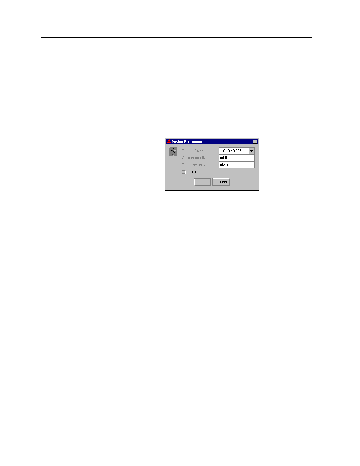
Double-click on the Cajun P120 Manager icon. The Device
Parameters dialog box opens.
Figure 1-1. Device Parameters Dialog Box
Managing
Different
Devices
2.
Enter the IP address of the Cajun P120 Device you want to manage
in the
3.
Enter the read community name in the
4.
Enter the write community name in the
5.
To save the parameters, check the
configurations will appear in the
box.
6.
Click
Or
1.
Double-click on the Cajun P120 Manager icon. The Device
Parameters dialog box appears.
2.
Select an IP address from the
3.
Click
To manage a different device:
1.
From the Cajun P120 Manager, select
Parameters dialog box opens.
Device IP Address
OK
. The Cajun P120 Device Manager opens.
OK
. The Cajun P120 Device Manager opens.
field.
Get Community
Set Community
save to file
Device IP Address
Device IP Address
File > Change IP
field.
field.
checkbox. Saved
dropdown list
dropdown list box.
. The Device
2.
3 Cajun P120 Manager User Guide
Follow the instructions above to select a different Cajun P120
Device to manage.
Page 11

Introduction
* Note:
This feature is only available if you have installed the
Cajun P120 Manager as a standalone management
application.
The User Interface
The user interface consists of the following elements:
Application Tabs
•
the Cajun P120 Device.
Tree View
•
representation of the modules and ports of the Cajun P120 Device.
Chassis View
•
Device.
Menu Bar
•
functions.
Application Toolbar
•
management functions.
- Tabs for switching between the various views of
- A resizeable window containing a hierarchical
- A graphical representation of the Cajun P120
- Menus for accessing Cajun P120 management
- Toolbar buttons for accessing Cajun P120
Get/Set Toolbar
•
- Toolbar buttons for viewing and changing port
and LAG configuration.
Dialog Area
•
- A resizeable window where all dialog boxes and
tables first appear.
•
Desktop
- A resizeable window where the Chassis View and all
floating and minimized dialog boxes and tables are displayed.
Status Line
•
- Displays the communication status between the
Cajun P120 Manager and the Cajun P120 Device.
Cajun P120 Manager User Guide 4
Page 12

Chapter 1
The figure below shows the user interface, with its various parts labeled.
Figure 1-2. Cajun P120 User Interface
When you hold the cursor over a port’s icon in the Chassis View, a label
appears with the port number, its VLAN ID, and the current fault that
occurred on the port.
Tree View
To resize the three main areas of the user interface, the Tree View, the
Chassis View, and the Dialog Area, use the splitter bars and their arrows.
The Tree View shows a hierarchical representation of the structure of the
Cajun P120 Device. To select ports or modules, click on their icons in the
Tree View. When an element is selected in the Tree View, the
corresponding element is selected in the Chassis View.
The highest level of the Tree View shows the device’s module. The second
level shows ports. This includes ports on an expansion module.
To expand the view of a contracted element in the tree or to contract the
view of an expanded element in the tree:
Double-click the element.
Or
Click the
+
or - symbol next to the element you want to expand or
contract.
5 Cajun P120 Manager User Guide
Page 13

Chassis View
Introduction
The Chassis View is a graphical representation of the Cajun P120 Device.
The Chassis View shows all of the device’s ports, including ports on the
expansion module (when present). The color of the modules and ports in
the Chassis View reflects their status.
When viewing selected tables, the color of the port indicates the standing
of the port with regard to the application. For example: When creating a
Link Aggregation Group (LAG), ports that can be selected appear white in
the Chassis View. The port selected to be the base port appears dark blue.
The ports selected to be additional ports appear cyan.
The following table provides a list of the possible port colors in the Chassis
View and their meaning.
Table 1-1. Chassis View Port Colors
Color Meaning
Green The port is enabled, and its status is Okay.
Yellow The port is enabled, and its status is Warning.
Red The port is enabled, and its status is Fatal.
Light Gray The port is disabled.
Dark Gray The port is not associated with the selected VLAN.
White The port is logically available for assignment.
Dark Blue The port has been assigned the primary position in an
application.
Cyan The port has been assigned the secondary position in an
application.
Cajun P120 Manager User Guide 6
Page 14
Chapter 1
GBIC Ports
Some Cajun P120 expansion modules contain GBIC (GigaBit Interface
Converter) ports that house removable transceiver modules. The Chassis
View reflects the management status of the ports. The following table
shows the possible appearances of these ports in the Chassis View and
provides the corresponding management status of the port.
Table 1-2. GBIC Port Status
GBIC Port Status
The GBIC port contains a supported transceiver module.
There is no transceiver module present in the GBIC port.
The transceiver module in the GBIC port is not supported.
The transceiver module in the GBIC port is of an unknown
type.
GBIC ports that contain the following types of transceiver modules can be
configured:
• Supported transceiver modules.
• No transceiver modules.
• Unknown transceiver modules.
GBIC ports that contain unsupported transceiver modules can not be
configured.
7 Cajun P120 Manager User Guide
Page 15

Introduction
Selecting
Elements
You can select modules and ports.
To select a module:
1.
In the Chassis View, click the module’s label.
Or
In the Tree View, click the module’s icon. The module’s label is
highlighted in the Chassis View and the Tree View.
To select a port:
In the Chassis View, click the port.
To select multiple ports, press
—
additional ports to be selected.
Or
In the Tree View, click the port’s icon. The port is highlighted in the
Chassis View and the Tree View.
CTRL
while clicking the
Application Tabs
You can access different views of the device using the Application Tabs.
The application tabs in the Cajun P120 Manager include:
To switch to a different view of the Cajun P120 Device, click the
appropriate application tab. The selected view opens.
* Note:
Device Manager
•
device configuration and Port RMON.
Device SMON
•
for the Cajun P120 Device.
If Cajun SMONMaster for the Cajun P120 is not installed on
your system, the
- View the Cajun P120 Device Manager for
- View SMON (Switch Monitoring) information
Device SMON
tab does not appear.
Cajun P120 Manager User Guide 8
Page 16
Chapter 1
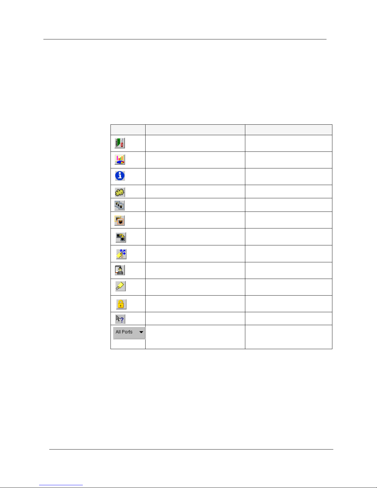
Application Toolbar
The Application Toolbar provides shortcuts to the main Chassis View
functions.
The table below describes the buttons on the Application Toolbar and
gives the equivalent menu options.
Button Description Menu Item
Table 1-3. Application Toolbar
Sets the device manager to
Configuration mode.
Sets the device manager to Port
RMON mode.
Displays the Device Information
dialog box.
Displays the VLAN window.
View > Configuration
View > Port RMON
Actions > Device
Information
Actions > Virtual LANs
Displays the LAG table.
Displays the Port Redundancy
table.
Starts the Port Mirroring wizard.
Displays the IP Multicast Filtering
dialog box.
Displays the Managers Trap Table.
Displays addresses of devices
connected to the switch.
Displays the Security table.
Opens the on-line help.
Selects a VLAN. Ports that are not
on the selected VLAN appear
dark gray in the Chassis View.
Actions > Link Aggregation
Actions > Port Redundancy
Actions > Port Mirroring
Actions > IP Multicast
Filtering
Actions > Manager Trap
Table
Actions > Switch
Connected Addresses
Actions > Security
Help > Contents
When you place the cursor on a toolbar icon for one second, a label
appears with the name of the button.
9 Cajun P120 Manager User Guide
Page 17
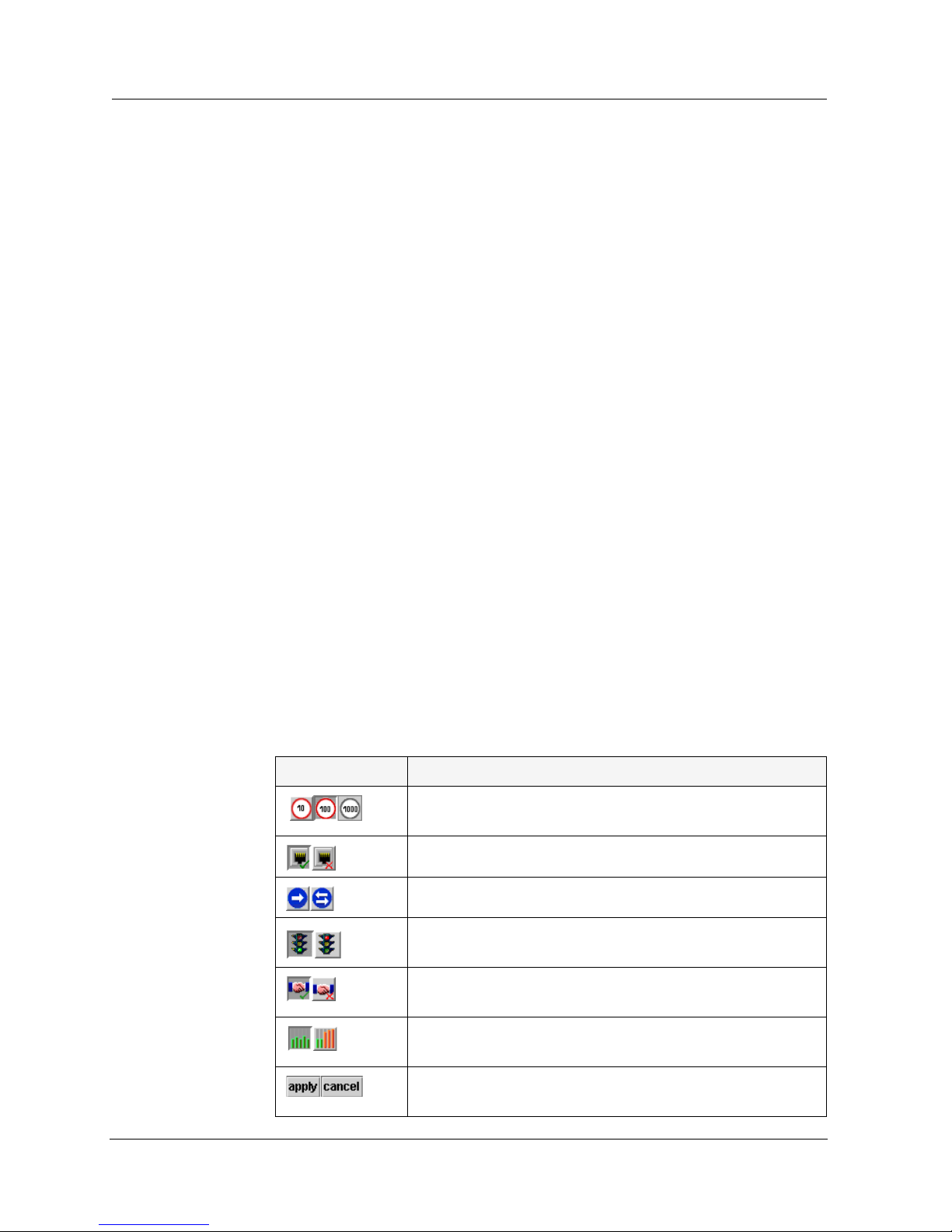
Get/Set Toolbar
The Get/Set Toolbar provides buttons for getting and setting configuration
parameters for selected ports.When a port is selected, its configuration is
reflected on the Get/Set Toolbar. Each group of buttons represents the
various possible states of a configuration parameter. For example: The first
group of buttons represents the possible speed of a port - 10 Mbps, 100
Mbps, or 1000 Mbps. If the center button is depressed, the port is
currently configured to operate at 100 Mbps.
Selected ports can be configured using the Get/Set Toolbar. To change the
configuration of a port, click the button representing the value of the
parameter you want to apply to the port. Click
with the changes. Click
applicable to the selected port are dimmed.
Multiple ports can be simultaneously configured using the
Get/Set Toolbar. When multiple ports whose configurations are not
identical are selected, only the parameters whose settings are identical on
the selected ports are reflected in the Get/Set Toolbar. For example, if a
port operating at full duplex and a port operating at half duplex are
selected, neither of the duplex mode buttons on the Get/Set Toolbar are
depressed.
apply
to update the device
cancel
to discard the changes. Options not
Introduction
The table below displays the buttons on the Get/Set Toolbar and explains
their functions and settings.
Table 1-4. Get/Set Toolbar
Button Description
Get and set the port’s speed: 10 Mbps, 100 Mbps, 1000
Mbps.
Get and set the port’s status: Enabled, Disabled.
Get and set the port’s mode: Half duplex, Full duplex.
Get and set the port’s Flow Control mode:
FlowControl on, FlowControl off.
Get and set the port’s auto-negotiation status:
Auto-negotiation Enabled, Auto-negotiation Disabled.
Get and set the port’s priority: Regular priority, High
priority.
Apply or cancel the configuration changes made with the
Get/Set Toolbar.
Cajun P120 Manager User Guide 10
Page 18
Chapter 1
Dialog Area
Desktop
The area to the right of the Chassis View is where all dialog boxes, tables,
and wizards first open. This area can be resized by dragging the vertical
splitter bar with the mouse. When a dialog box, table, or wizard opens, it
replaces the current dialog box open in the Dialog Area. To view more
than one dialog box or table simultaneously, click on the pushpin in
the upper right-hand corner of the dialog box. The dialog box becomes a
floating dialog box and moves to the Desktop.
To restore a dialog box to the Dialog Area, click on the toolbar button or
symbol that opened the dialog box. The dialog box returns to the Dialog
Area.
The central section of the application window is the Desktop. This area
can be resized by dragging the vertical splitter bar with the mouse.
Floating dialog boxes and tables can be resized. The Chassis View and
floating dialog boxes and tables can also be minimized. Minimized
windows are shown at the bottom of the Desktop.
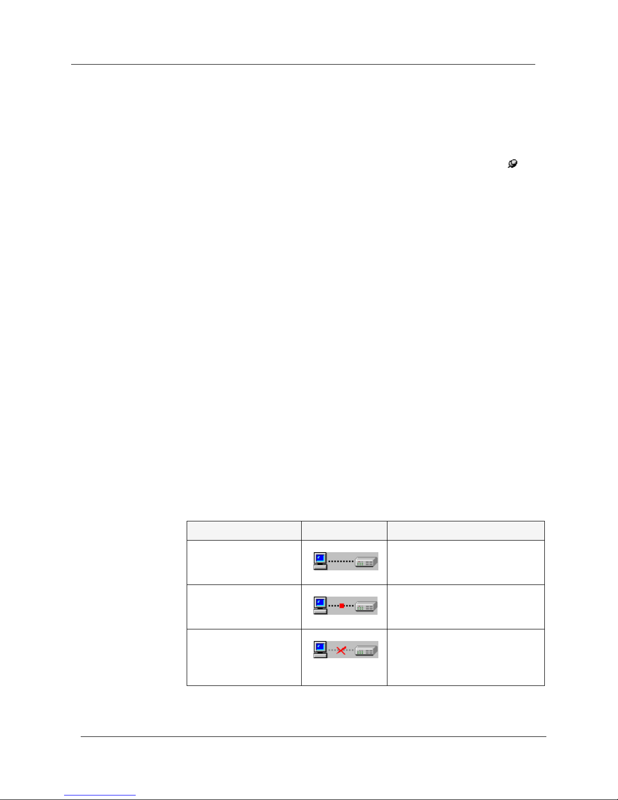
Status Line
The Status Line shows the communication status between the application
and the Cajun P120 Device. The Status Line displays a status message and
an appropriate graphic. The table below shows the possible statuses with
their corresponding graphics, and gives a short explanation for each
status.
Table 1-5. Communication Statuses
Status Graphic Description
Ready The application is ready to
communicate with the
Cajun P120 Device.
Communicating The application is currently
communicating with the
Cajun P120 Device.
Communication Error The last attempted
communication with the
Cajun P120 Device was not
successful.
11 Cajun P120 Manager User Guide
Page 19

Cajun P120 Modes
The Cajun P120 application has two modes: Configuration mode and Port
RMON mode. When in configuration mode, you can view and change the
configuration of the Cajun P120 Device and individual ports. When in
Port RMON mode, you can view graphical representations of the traffic
on individual ports.
To switch to configuration mode:
Click .
Or
Introduction
Select
To switch to Port RMON mode:
Click .
Or
Select
View > Configuration
View > Port RMON
.
.
Cajun P120 Manager User Guide 12
Page 20

Chapter 1
Using Dialog Boxes and Tables
Dialog boxes and tables in the Cajun P120 Manager application have a
common set of icons. The following table displays the icons and explains
their functions:
Table 1-6. Dialog Box Icons
Icon Function
Refreshes the information in the table or dialog box. This clears
any changes made to the table or dialog box and not yet sent to
the device.
Sends the information from the table or dialog box to update the
device.
Adds a row to the table.
Starts a wizard.
Managing Tables
The Cajun P120 Manager interface informs you of the status of each row
in a table. The following table shows a list of symbols which can appear at
the start of a table row, with their corresponding explanations.
Symbol Explanation
Deletes the selected rows of the table.
Undoes all changes to the selected row in a table.
Table 1-7. Table Symbols
The row has not changed since the device was last updated.
The row is a new entry.
The row is to be deleted.
The information in the row has been changed by the user.
To undo all the changes made to a table, click . To undo changes
made to a selected row, click . When all changes are finalized, click
13 Cajun P120 Manager User Guide
to update the device.
Page 21

Using Cajun P120 Help
This section explains how to use the on-line help in the Cajun P120
Device Manager. The on-line help can be opened to the contents page or
directly to a topic of interest.
Opening the Help to the Contents Page
To open the help to the contents page:
Introduction
1.
Select
Help > Contents
. The on-line help opens to the contents page.
Opening the Help to a Topic of Interest
To open the help directly to a topic of interest:
1.
Click . The cursor changes to the shape of a hand.
2.
Click on a point of interest in the Cajun P120 Device Manager. The
help opens to a topic explaining the feature that was clicked.
Cajun P120 Manager User Guide 14
Page 22

2
Device Configuration
This chapter explains how to view and set the various configuration
parameters relevant to the Cajun P120. It includes the following
sections:
Viewing Device Information
•
about the Cajun P120 Device.
Viewing LAG Configuration
•
LAG on a Cajun P120 Device.
Viewing Port Configuration
•
ports on the Cajun P120 Device.
Resetting the Device
•
- Reset the Cajun P120 switch.
- View high-level information
- View information specific to a
- View information specific to the
Cajun P120 Manager User Guide 16
Page 23

Chapter 2
Viewing Device Information
The Device Information dialog box provides you with high-level
information specific to a Cajun P120 Device. To view information about
the Cajun P120 switch:
1.
Click .
Or
In configuration mode, click .
Or
Select
box opens.
Actions > Device Information
Figure 2-1. Device Information Dialog Box
. The Device Information dialog
The Device Information dialog box provides detailed information about
the device such as the system name, description, contact, and location,
the type of device, and its MAC address.
For a full description of all fields in the Device Information dialog box,
refer to Appendix B, Configuration Fields.
17 Cajun P120 Manager User Guide
Page 24

Viewing LAG Configuration
The LAG Configuration dialog box provides you with information specific
to a selected LAG. To view the configuration of a LAG, when in
configuration mode, click on the LAG symbol in the Chassis View. The
LAG Configuration dialog box opens.
Figure 2-2. LAG Configuration Dialog Box
Device Configuration
The LAG Configuration dialog box provides detailed information about
the LAG, such as the LAG type, its status, mode of operation, and priority.
The Get/Set Toolbar provides an alternative, quick method to view and
change the LAG’s configuration. For more information on the Get/Set
Toolbar, refer to “Get/Set Toolbar” on page 8.
* Note:
For a full description of all configuration fields in the LAG Configuration
dialog box, refer to Appendix B, Configuration Fields.
Cajun P120 Manager User Guide 18
The information fields in the LAG Configuration dialog box
may change according to the type of port selected.
Page 25

Chapter 2
Viewing Port Configuration
The Port Configuration dialog box provides you with information specific
to a selected port. To view the configuration of a port:
1.
When in configuration mode, click on the port symbol in the
Chassis View or Tree View. The Port Configuration dialog box
opens.
Figure 2-3. Port Configuration Dialog Box
The Port Configuration dialog box provides detailed information about
the port, such as the port type, its status, mode of operation, and any
faults occurring on the port.
The Get/Set Toolbar provides an alternative, quick method to view and
change the port’s configuration. For more information on the Get/Set
Toolbar, refer to “Get/Set Toolbar” on page 10.
* Note:
For a full description of all configuration fields in the Port Configuration
dialog box, refer to Appendix B, Configuration Fields.
For more information on the User Interface, refer to “Using Dialog Boxes
and Tables” on page 13.
19 Cajun P120 Manager User Guide
The information fields in the Port Configuration dialog box
may change according to the type of port selected.
Page 26

Resetting the Device
To reset the Cajun P120 Device:
Device Configuration
1.
2.
Select
Click
Actions > Reset
Yes
. The device resets.
. A confirmation dialog box appears.
Cajun P120 Manager User Guide 20
Page 27

3
Port RMON
This chapter explains the port RMON options of the Cajun P120 Device.
It includes the following sections:
Displaying the Port RMON Window
•
RMON window.
The Port RMON Window
•
Port RMON window.
Traffic Selection
•
in the Port RMON window.
For more information on RMON, refer to RMON in The Reference Guide.
-An explanation on selecting traffic to monitor
- An explanation of the parts of the
- Displaying the Port
Cajun P120 Manager User Guide 22
Page 28

Chapter 3
Displaying the Port RMON Window
To view Port RMON information, you must be in Port RMON mode. To
switch to Port RMON mode:
Click .
Or
Select
To display the Port RMON window, select a port in the Chassis View or
Tree View. The Port RMON window opens.
View > Port RMON
Figure 3-1. Port RMON Window
.
The Port RMON Window
The Port RMON window includes three sections. A pie chart is displayed
at the top of the window. In the center of the window is a graph section.
At the bottom of the window is a list of traffic types.
23 Cajun P120 Manager User Guide
Page 29

The Pie Chart
The pie chart shows the relative amounts of broadcast, multicast, and
unicast traffic on the selected port. The legend to the right of the pie chart
shows the color which represents each of these types of traffic.
The Traffic Graph
The graph charts various types of traffic over time. Each type of traffic is
represented by a line of a different color. Using the mouse, you can view
traffic statistics, zoom in or out of the graph, and scroll within the graph to
view parts of the graph which are currently hidden.
When changing the view on the graph, the graph freezes. To unfreeze the
graph and restore the display to the default display, click on the graph.
Port RMON
Viewing
Traffic
Statistics
Zooming In
and Out of
the Graph
Scrolling
within the
Graph
To view traffic statistics, hold the mouse over a point on the graph
representing the traffic for which you would like to see statistics. After
two seconds, an info box appears displaying the name of the traffic type
represented by the line in the graphic, and the traffic rate at the selected
point in time.
To view a graph of all the traffic on the selected port from the time the
application was opened, double-click in the graph. The graph shows all of
the traffic on the port from the time the application was opened until
now.
To zoom in on a portion of the graph, press
the graph using the mouse. The graph zooms in and shows only the
portion of the graph that was selected.
To scroll within the graph, hold the left mouse button down while moving
the mouse from the graph in the direction you want to scroll. The graph
scrolls in the selected direction.
Traffic Selection
SHIFT
and select a portion of
The bottom of the Port RMON window contains a list of various types of
traffic. Each traffic type has a checkbox next to it. Only traffic types whose
checkboxes are checked are displayed in the Port RMON graph.
For a full description of the traffic types, refer to Appendix C, Traffic Types.
Cajun P120 Manager User Guide 24
Page 30

4
VLANs
This chapter provides the information and instructions you need to use
VLANs. It includes the following topics:
• Creating and Editing VLANs
• Viewing the VLANs Dialog Box
• Configuring VLANs
• Editing VLAN Member Switch Ports
• Edit VLAN Tagging Parameters
• Updating the Device
For more information, refer to VLANs in The Reference Guide.
Creating and Editing VLANs
The building blocks of VLANs are switch ports. To build a new VLAN you
need to define a VLAN name and number and then decide which switch
ports will make up the VLAN. VLAN #1 is named Default. All ports are
initially associated with this VLAN.
Cajun P120 Manager User Guide 25
Page 31

Viewing the VLANs Dialog Box
To view VLAN names, numbers, and component switch ports:
Click .
Or
VLANs
Select
Actions > Virtual LANs
Figure 4-1. VLANs Dialog Box
. The VLANs dialog box opens.
The tree in the VLANs dialog box shows all of the VLANs. To view the
member ports of a VLAN, double-click the VLAN’s name or click the
handle next to the VLAN’s name. The tree expands to show the ports
associated with the VLAN. Ports that use tagging mode have yellow tags
attached to their port symbols. In the Chassis View, the ports associated
with the selected VLAN, appear in color. All other ports appear dark gray.
Cajun P120 Manager User Guide 26
Page 32

Chapter 4
Configuring VLANs
To create a new VLAN:
1.
Click . A new VLAN appears in the list.
2.
Enter a name and number for the VLAN into the appropriate fields.
The VLAN is added immediately.
* Note:
To delete a VLAN:
To edit VLAN names:
Valid VLAN numbers are between 1 and 3071.
1.
Select the VLAN you want to delete.
2.
Ensure that there are no ports associated with the VLAN.
3.
Right-click on the VLAN symbol and select
deleted.
1.
Select the VLAN whose name you want to edit.
2.
Right-click on the VLAN symbol and select
opens.
3.
Enter the new name for the VLAN.
Click
OK
. The VLAN name is changed.
4.
Editing VLAN Member Switch Ports
Delete
Rename
. The VLAN is
. A dialog box
To assign switch ports to VLANs:
1.
2.
Or
1.
* Note:
27 Cajun P120 Manager User Guide
Click on one or more ports in the Chassis View or Tree View.
Drag the ports until they are over a VLAN icon in the tree.
Drag ports from existing VLANs to the desired VLAN’s icon. The
ports are added to the desired VLAN in the tree.
You can reassign the Management VLAN ID by dragging the
Agent icon over the desired VLAN’s icon.
Page 33

VLANs
To disassociate switch ports from VLANs, associate the ports to the default
VLAN (VLAN 1).
* Note:
Ensure that linked ports are assigned to the same VLAN.
Editing VLAN Tagging Parameters
To edit the VLAN Tagging parameters of a port:
1.
Right-click on the port in the VLANs table.
2.
Select the VLAN Tagging mode for the selected port.
Or
1.
Open the Port Configuration dialog box.
2.
Set the
VLAN Tagging Mode
Updating the Device
Ports whose VLAN information has changed appear dimmed in the
VLANs tree. To update the device with the changes, click .
field to the desired value.
For more information on the User Interface, refer to “Using Dialog Boxes
and Tables” on page 13.
Cajun P120 Manager User Guide 28
Page 34

Link Aggregation Groups
5
This chapter provides the information and instructions you need to
create and use Link Aggregation Groups (LAGs). It includes the
following topics:
• LAGs Overview
• Viewing the LAG Table
• Creating LAGs
• Editing LAGs
• Deleting LAGs
LAGs Overview
Link Aggregation Groups (LAGs) provide a method of creating a highbandwidth link. A LAG consists of a group of ports acting as a single
logical port. All ports participating in a LAG must have the same
configuration.
For more information on LAGs, refer to Link Aggregation Groups (LAGs) in
The Reference Guide.
Cajun P120 Manager User Guide 29
Page 35

Viewing the LAG Table
To view the LAG Table:
Click .
Or
Link Aggregation Groups
Select
Actions > Link Aggregation
Figure 5-1. LAG Table
. The LAG table opens.
Each row of the LAG table represents a valid Link Aggregation Group and
provides the following information:
• The LAG name.
• The number of the LAG’s base port.
• The number of ports assigned to the LAG.
When a LAG is selected, the ports in the LAG appear highlighted in the
Chassis View and Tree View.
Cajun P120 Manager User Guide 30
Page 36

Chapter 5
Creating LAGs
To create a new LAG:
1.
2.
Click . The LAG Wizard starts.
Follow the instructions on each of the LAG Wizard’s dialog boxes.
* Note:
Editing LAGs
To edit an existing LAG:
When editing a LAG, the LAG Wizard’s dialog boxes will display the
current LAG configuration parameters. If you want to keep the values
currently displayed in one of the dialog boxes, click
3.
1.
2.
3.
4.
Finish
Click
Device, and the LAG table is refreshed.
Ports that participate in a Port Redundancy can not be
assigned to a LAG.
Select a LAG by clicking on the row representing the LAG.
Click . The LAG Wizard starts.
Follow the instructions on each of the LAG Wizard’s dialog boxes.
Click
P120 device, and the LAG table is refreshed.
. The LAG information is uploaded to the Cajun P120
Finish
. The LAG’s new configuration is uploaded to the Cajun
Next
.
Deleting LAGs
To delete an existing LAG:
1.
2.
3.
4.
For more information on the User Interface, refer to “Using Dialog Boxes
and Tables” on page 13.
For more information on tables, refer to “Managing Tables” on page 13.
31 Cajun P120 Manager User Guide
Select a LAG by clicking on the row representing the LAG.
Click .
The LAG is marked with the symbol.
Click to update the device.
Page 37

IP Multicast Filtering
6
This chapter provides information on configuring IP Multicast Filtering
on the Cajun P120 Device. It includes the following sections:
IP Multicast Filtering Overview
•
Multicast Filtering.
Configuring IP Multicast Filtering
•
the IP Multicast Filtering dialog box and descriptions of the
parameters in the IP Multicast Filtering dialog box.
IP Multicast Filtering Overview
IP Multicast Filtering provides a method for distributing high-bandwidth
applications to specific stations that may be configured on different
VLANs. It allows for a single copy of the data to be propagated on the
network, copied only when the paths to endstations diverge.
- A brief overview of IP
- Instructions on accessing
For more information on IP Multicast and IP Multicast Filtering, refer to
IP Multicast in The Reference Guide.
Cajun P120 Manager User Guide 32
Page 38

Chapter 6
Configuring IP Multicast Filtering
To configure IP Multicast Filtering:
Click .
Or
Select
Actions > IP Multicast Filtering
. The IP Multicast Filtering
dialog box opens.
Figure 6-1. IP Multicast Filtering Dialog Box
The IP Multicast Filtering dialog box enables you to configure IP Multicast
filtering parameters on the Cajun P120 Device. It contains the following
parameters:
Parameter Description
Filtering Mode
Host Aging Time
33 Cajun P120 Manager User Guide
Table 6-1. IP Multicast Filtering Parameters
The mode of operation of IP Multicast Filtering
on the device. Possible modes are:
enable
•
on the device.
disable
•
enabled on the device.
The amount of time (in seconds) allowed to pass
from a host’s last IP Multicast request before the
device stops forwarding a multicast session to a
host. The valid range for this parameter is
30 - 1800 seconds.
- IP Multicast Filtering is enabled
- IP Multicast Filtering is not
Page 39

Table 6-1. IP Multicast Filtering Parameters (Continued)
Parameter Description
IP Multicast Filtering
Router Aging Time
Delay Time
The amount of time (in seconds) allowed to pass
from a router’s last IP Multicast control packet
before the device will stop forwarding all
multicast sessions to a router. The valid range
for this parameter is 30 - 7200 seconds.
The amount of time (in seconds) the device
waits from receiving a request for a new IP
Multicast session until IP Multicast filtering
begins. This time allows other hosts to report to
the device. The valid range for this parameter is
1- 300 seconds.
Enter the IP Multicast filtering parameters for the Cajun P120 Device.
To apply the changes, click .
To refresh the information in the IP Multicast Filtering dialog box,
click .
Cajun P120 Manager User Guide 34
Page 40

Port Redundancy
7
This chapter provides the information and instructions you need to use
the Port Redundancy feature. It includes the following topics:
• Overview of Port Redundancy
• Viewing the Port Redundancy Table
• Adding a Port Redundancy
• Deleting Port Redundancies
• Updating the Device
Overview of Port Redundancy
Port Redundancy enables you to define a redundancy relationship
between any two ports in a device. One port is defined as the primary
port and the other as the secondary port. In case the primary port link
fails, the secondary port will take over. This connection between the two
ports is called a Port Redundancy.
* Note:
Port Redundancy can not be used when Spanning Tree is
activated.
CAUTION
Cajun P120 Manager User Guide 36
For more information on Port Redundancy, refer to Redundancy in The
Reference Guide.
Ports that are assigned to a LAG can not participate in a Port
Redundancy.
Page 41

Chapter 7
Viewing the Port Redundancy Table
To view the Port Redundancy table:
Click .
Or
Select
opens.
Actions > Port Redundancy
Figure 7-1. Port Redundancy Table
. The Port Redundancy Table
The Port Redundancy table provides a list of all port redundancies
configured on the device, with their respective primary and secondary
ports. When you select a row in the Port Redundancy table, the ports in
the redundancy are highlighted in the Chassis View and the Tree View.
37 Cajun P120 Manager User Guide
Page 42

Adding a Port Redundancy
To add a new Port Redundancy:
1.
Click . The Port Redundancy Wizard opens.
2.
Follow the instructions on each of the Port Redundancy Wizard’s
dialog boxes.
Port Redundancy
3.
Or
1.
2.
3.
* Note:
* Note:
Finish
Click
the Cajun P120 Device, and the Port Redundancy table is
refreshed.
Click .
Enter the number of the primary port in the
Enter the number of the secondary port in the
table is updated with the new Redundancy.
A maximum of four port redundancy pairs can be configured
on the Cajun P120 Device.
Ports that have already been designated in one redundancy
scheme, may not be selected for another one.
. The new Port Redundancy information is uploaded to
Deleting Port Redundancies
To delete an existing Port Redundancy:
Primary
Secondary
field.
field. The
1.
Click . The deleted Port Redundancy is marked with the
symbol.
* Note:
Cajun P120 Manager User Guide 38
To edit Port Redundancy information, you must delete the
Port Redundancy, and create a new one.
Page 43

Chapter 7
Updating the Device
To update the device with all changes made to the Port Redundancy table,
click . The device is updated with all of the new information.
To discard all changes made to the Port Redundancy table, click . All
changes made to the Port Redundancy table are discarded.
For more information on the User Interface, refer to “Using Dialog Boxes
and Tables” on page 13.
For more information on tables, refer to “Managing Tables” on page 13.
39 Cajun P120 Manager User Guide
Page 44

Port Mirroring
8
Port Mirroring copies all received and transmitted packets (including
local traffic) from a source port to a predefined destination port, in
addition to the normal destination port of the packets.
For more information, refer to Port Mirroring in The Reference Guide.
This section explains how to configure a Port Mirroring pair on the
Cajun P120 Device.
Do not change the VLAN of the source or destination port while
the port mirroring mechanism is operating.
CAUTION
Configuring Port Mirroring
To configure Port Mirroring:
Click .
Or
Select
If Port Mirroring is not currently active on the device, the Port Mirroring
Wizard gives instructions on defining and activating the Port Mirroring
feature.
If Port Mirroring is currently active on the device, the Port Mirroring
Wizard offers the choices of deleting or editing the existing Port
Mirroring configuration.
1.
Follow the instructions on each of the Port Mirroring Wizard’s
dialog boxes.
2.
Click
the Cajun P120 Device and is operative immediately.
Actions > Port Mirroring
Finish
. The new Port Mirroring information is uploaded to
. The Port Mirroring Wizard opens.
Cajun P120 Manager User Guide 41
Page 45

Trap Managers
9
Configuration
This chapter provides the information and instructions you need to
configure managers for the Cajun P120 Device. It includes the following
topics:
• Trap Manager Overview
• Viewing the Managers Table
• Editing the Trap Managers Table
Trap Manager Overview
In the event of a fault or an unusual occurrence, the Cajun P120 can
send traps to one or more Network Management Stations (NMS). To
enable this feature, you must configure the Cajun P120 with a list of the
managers’ workstations. Traps are then sent to the stations listed in the
Managers table.
* Note:
Up to five managers may be assigned per device. However, it
is recommended to keep the list limited to actual and
relevant managers so as not to place undue stress on the
network.
Cajun P120 Manager User Guide 43
Page 46

Viewing the Managers Table
To view the Managers Trap table:
Click .
Or
Trap Managers Configuration
Select
Actions > Trap Managers
Figure 9-1. Trap Managers Table
. The Trap Managers table opens.
The Trap Managers table displays the IP addresses of the managers.
Editing the Trap Managers Table
To add managers to the table:
1.
Click .
2.
Enter the IP address of the designated management station.
3.
Repeat the procedure for each manager.
Cajun P120 Manager User Guide 44
Page 47

Chapter 9
To remove managers from the table:
1.
Click on the row with the managers IP address.
2.
Click .
3.
Repeat the procedure for each manager.
For more information on the User Interface, refer to “Using Dialog Boxes
and Tables” on page 13.
For more information on tables, refer to “Managing Tables” on page 13.
45 Cajun P120 Manager User Guide
Page 48

Switch Connected
10
Addresses
The Switch Connected Addresses feature allows you to see which
devices are connected to the ports on the Cajun P120 Device. Keeping
track of this information in the network can increase efficiency and
security, and assist in troubleshooting network problems.
Viewing the Switch Connected for Device Window
The Switch Connected Addresses window provides a list of MAC
addresses along with the ports to which they are attached. To view the
list of connected stations:
Click .
Or
Select
Connected Addresses dialog box opens.
Figure 10-1. Switch Connected Addresses for Device Dialog Box
All the connections to the Cajun P120 are listed with their respective
ports in the Switch Connected Addresses window. The rows of the
Switch Connected Addresses window comprise the following
information:
Actions > Switch Connected Addresses
. The Switch
Cajun P120 Manager User Guide 47
Page 49

Mac Address
•
•
device.
Port
- The number of the port in the device.
- The MAC addresses of the stations connected to the
Sorting the List of Stations
To sort the list of stations, click on a column heading to sort by that
column. To switch the order of the sort (e.g. from ascending to
descending), click again on the column heading of the field by which the
list is sorted.
For more information on the User Interface, refer to “Using Dialog Boxes
and Tables” on page 13.
Switch Connected Addresses
Cajun P120 Manager User Guide 48
Page 50

Security
11
This chapter provides information on configuring security for ports on
the Cajun P120 Device. It includes the following sections:
Security Overview
•
Cajun P120 Device.
Configuring Port Security
•
Security table and configuring port security.
Security Overview
The Security feature for Cajun P120 ports prevents unauthorized devices
from transmitting or receiving information through the port. If no device
is attached to the port when security is enabled, the port is effectively
locked. If a device is attached to the port when security is enabled, only
that device will be capable of receiving or transmitting information
through the port.
- A brief overview of port security on the
- Instructions on accessing the
Cajun P120 Manager User Guide 49
Page 51

Configuring Port Security
To configure Port Security:
Click .
Or
Security
Select
The Security table enables you to enable and disable security on Cajun
P120 ports. To enable security on a port, check the Security Status
checkbox next to the port.
Actions > Security
Figure 11-1. Security Table
. The Security table opens.
To disable security on a port, uncheck the Security Status checkbox next
to the port.
To apply the changes, click .
To refresh the information in the Security table, click .
Cajun P120 Manager User Guide 50
Page 52

A
File Menu
Menus
This appendix gives the full menu structure of the menus in the
Cajun P120 Management Application.
Table 11-1. File Menu
Item Description
Refresh
Change IP
version only)
Exit
View Menu
Item Description
Configuration
Port RMON
(In Standalone
Refreshes the display with information from the
device.
Opens the Device Parameters dialog box for
selecting a different device to manage.
Exits the Chassis View.
Table 11-2. View Menu
Switches the Manager to configuration mode.
Switches the Manager to monitoring mode.
Cajun P120 Manager User Guide 51
Page 53

Actions Menu
Item Description
Table 11-3. Actions Menu
Help Menu
Device Information
Virtual LA Ns
Link Aggregation
Port Redundancy
Port Mirroring
IP Multicast Filtering
Trap Managers
Switch Connected
Addresses
Security
Reset Device
Displays information for the device.
Displays and enables configuration of VLANs.
Displays the LAG table.
Displays and enables configuration of software
redundancies.
Allows copying of all transmitted and received
packets from one port to another.
Displays IP Multicast Filtering information.
Displays managers and traps configuration
information.
Displays a list of stations connected to each of the
device’s ports.
Displays the Security table.
Resets the device.
Table 11-4. Help Menu
Item Description
Contents
About Cajun P120
Manager
Cajun P120 Manager User Guide 52
Opens the help module contents page for
information.
Copyright information about Cajun P120 Manager.
Page 54

B
Configuration Fields
Field Description
Administrative Status
AutoNegotiation Mode
BUPS Module CS
The state of the selected port, ports, or ports in the
selected LAG:
Enabled
•
transmit and receive packets.
Disabled
•
transmit or receive packets.
The configured state of the Auto-Negotiation
protocol between two stations. When enabled,
Auto-Negotiation detects the highest common
denominator for communication between
endstations, and sets both to the same highest
common setting. It also delivers remote link status.
For 10BaseT and 100BaseT ports, Auto-Negotiation
determines the speed and Duplex Mode of
communication between the endstations. For
Gigabit ports, Auto-Negotiation determines the
Flow Control setting of the ports.
For more information, refer to
The Reference Guide
The version of the BUPS (BackUp Power Supply)
module. The version is updated whenever there is a
functional modification to the module.
- The port is enabled and can
- The port is disabled and cannot
Auto-Negotiation
.
in
BUPS Module Type
Configuration Symbol
Contact
Domain Name
Cajun P120 Manager User Guide 53
The type of BUPS (BackUp Power Supply) module
in the selected module.
The version of the module. The version is updated
whenever there is a functional modification to the
module.
Individual responsible for maintenance of the
device.
The name of the PNNI routing domain in which
this node participates.
Page 55

Field Description
Configuration Fields
Duplex Mode
Expansion CS
Expansion Description
Expansion Type
Fault Messages
Filtering Mode
The state of communication of the selected port,
ports, or ports on the selected LAG. Possible values
are:
Full Duplex
•
- The port can send and receive
simultaneously.
Half Duplex
•
- The port can either receive or
send, but can not do both simultaneously.
The version of the expansion module. The version
is updated whenever there is a functional
modification to the module.
A description of the expansion module in the
selected module.
The type of expansion module in the selected
module.
A list of fault messages.
The mode of operation of the IP Multicast Filtering
on the device. Possible Modes are:
Enable
•
- IP Multicast Filtering is enabled on
the device.
Disable
•
- IP Multicast Filtering in not enabled
on the device.
Flow Control Mode
IEEE-802.1D STP Mode
IP Address
The state of flow control on the selected port, ports,
or ports on the selected LAG.
The state of Spanning Tree Protocol. Possible states
are:
Disable
•
- STP is disabled. This is the default
state.
Enable
•
- STP is enabled.
When activating STP, keep in mind that:
• All bridges should run STP.
• Redundancy applications and STP cannot co-
exist.
For more information refer to
Algorithm (STA)
in
The Reference Guide
Spanning Tree
.
The IP address of the device, manager, agent, or
neighbor device.
Cajun P120 Manager User Guide 54
Page 56

Appendix B
Field Description
LAG Functionality
LAG Name
LAG Type
Link Aggregation Group
Name
MAC Address
Max Frame Size
Module Type
Neighbor Sys Name
The physical media type of the . If the port
conforms to a certain standard (Repeater,
Transceiver, 10BaseT, etc.), this standard is
displayed. If the port does not conform to any
standard, Private is displayed.
The name of the selected LAG.
The type of LAG.
In Port Configuration: The name of the LAG of
which the port is a member. If the port is not a
member of a LAG, the Link Aggregation Name is
not in LAG
.
In LAG Configuration: The name of the LAG.
The MAC address of the device, agent, or ring
interface.
The maximum data frame size of supported by the
ELAN.
The module type.
The name of the remote device linked to the
interface.
Operational Status
Physical Location
Port Functionality
The warning level of the selected port, ports, or
ports on a selected LAG. Possible values are:
• OK
• Warning
• Fatal
The current physical location of the device.
The physical media type of the selected port. If the
port conforms to a certain standard (Repeater,
Transceiver, 10BaseT, etc.), this standard is
displayed. If the port does not conform to any
standard, Private is displayed.
55 Cajun P120 Manager User Guide
Page 57

Field Description
Configuration Fields
Port Priority Level
Port STP State
The priority level of packets exiting the port or
ports on the module. For effective transmission,
multimedia packets must be received isochronously
(at regular intervals). To ensure this, you can assign
priorities to packets coming out of a port.
Whenever traffic load is extreme and a port cannot
accept all incoming packets, packets sent from a
port with the highest priority will pass through
first. However, a fairness mechanism will allow low
priority packets to eventually enter the bus.
Possible values are:
• Regular
High
•
The state of the port in terms of the Spanning Tree
Protocol. The possible states are:
•
Disable
•
Blocking
- The port is disabled.
- STP is enabled and currently
blocking the port. The port is effectively
disabled to prevent the formation of a loop in
the network.
•
Forwarding
- The port is currently
forwarding information received.
Port Type
Port VLAN ID
Software Version
Speed Mode
System Description
System Name
The port type; optionally includes reference to the
module to which it is attached and port connector
type.
The number of the VLAN of which the port or ports
assigned to a LAG is a member. Change the number
in this field to move the port to another VLAN.
Untagged frames use this VLAN number.
The version of the application software running on
the module.
The speed of communication of the selected port,
ports, or ports on the selected LAG. Possible values
are:
Ethernet
•
Fast Ethernet
•
• Gigabit Ethernet
- 10 Mbps.
- 100 Mbps.
- 1000 Mbps.
A description of the type of system being used.
Logical name of the system as defined on the SNMP
agent of the device.
Cajun P120 Manager User Guide 56
Page 58

Appendix B
Field Description
Tagging Mode
The port’s or LAG’s operation mode regarding
VLANs. The possible modes are:
Clear
•
- Transmits each outgoing packet in
untagged format if it belongs to the port’s
VLAN. Otherwise, it discards the packet.
IEEE-802.1Q
•
- VLAN tagging, per IEEE
802.1Q VLAN standard. The port will transmit
frames with a VLAN ID of 1 - 3071.
57 Cajun P120 Manager User Guide
Page 59

C
Traffic Typ es
Field Description
BroadcastPackets
Received
Collisions Total number of Ethernet collisions in which the
CRC Errors Total number of Ethernet packets received at this
Fragments Total number of Ethernet packets received at this
Frames Too Long Total number of Ethernet packets received at this
Jabber Total number of Ethernet packets received at this
MulticastPackets
Received
Total number of good packets directed to the
broadcast address that were received on the port or
module.
port was involved.
port with FCS error and Framing error. This
indicates the number of corrupted packets received.
port whose octet count is less than the minimum
standard packet length.
port whose octet count is more than the maximum
standard packet length.
port that are too long and include CRC errors.
Total number of good packets received that were
directed to a multicast address. Note that this
number does not include packets directed to the
broadcast address.
Total Packets Received Total number of packets of valid frame length that
Unicast Total number of good packets received that were
Cajun P120 Manager User Guide 58
were received on the port.
directed to a unicast address.
Page 60

Index
A
Adding port redundancy
Application tabs
Application toolbar
C
Cajun P120 Management
connected stations
device configuration
port redundancy
Port RMON
VLANs
Cajun P120 modes
Chassis View
application toolbar
Get/Set toolbar
selecting elements
status line
Configuration fields
Configuring
devices
security
Counter fields
Creating VLANs
D
Desktop
Device
configuration
information
Dialog area
Dialog box symbols
E
Editing
VLAN member switch ports
VLANs
G
GBIC ports
Get/Set toolbar
25
11
25
16
50
8
9
47
16
36
22
12
6
9
10
8
11
53
58
25
16
17
11
13
7
10
38
27
H
Help menu
Help, using
How this manual is organized
How to
access the VLAN list
configure devices
configure port mirroring
configure port security
create VLANs
edit VLAN member switch ports
edit VLANs
select elements
use the application toolbar
use the Get/Set toolbar
view connected stations
view device information
view the port redundancy table
M
Managing different devices
Managing tables
Monitoring performance
O
OpenView (Solaris)
Organization
Overview security
P
Port
colors
GBIC
mirroring
RMON
Port redundancy
R
Redundancy, port
Running
Cajun P120 as a standalone management
application
52
14
viii
26
16
41
50
25
27
25
8
9
10
47
17
37
3
13
22
2
viii
49
6
7
41
22
36
36
3
Cajun P120 Manager User Guide 60
Page 61

Index
Cajun P120 Manager from UNIX 2
Cajun P120 Manager from Windows
Cajun P330 Manager from Windows
S
Security
configuring
overview
Selecting elements
Starting
Cajun P120 Manager
from Windows
Station connections
Status line
Switch connected addresses
Switching devices
Switching views
T
Table ro w symb o ls
Tree View
U
User interface
application tabs
Chassis View
desktop
dialog area
Get/Set toolbar
status line
toolbar
Tree View
49
9
5
11
49
11
11
5
50
11
8
1
2
47
47
3
8
13
3
8
6
10
Users of Cajun P120 management
2
2
Using
application toolbar
Cajun P120 help
Chassis View
dialog boxes
Get/Set toolbar
V
Viewing
connected stations
device information
port redundancy table
VLAN list
VLANs
accessing the dialog box
creating
editing
editing member switch ports
W
Who should use Cajun P120 Manager
25
25
26
13
9
14
6
10
47
17
37
26
27
viii
viii
61 Cajun P120 Manager User Guide
 Loading...