

Avaya P113F Installation Manual

Avaya
Installation Guide
P113F
S
TACKABLE ETHERNET SWITCH


Preface
Important Information
SAFETY PRECAUTIONS
CAUTION – TO REDUCE THE RISK OF ELECTRIC SHOCK AND FIRE
1. All servicing should be undertaken ONLY by qualified personnel. The parts inside the unit
CANNOT be serviced or repaired by the end user. Please call your service representative
for assistance.
2. Do NOT plug in, turn on or attempt to operate a damaged unit.
3. Ensure that the chassis ventilation slots in the unit are NOT BLOCKED.
4. Replace a “blown” fuse only with the same type and rating as is marked on the safety label
adjacent to the power inlet housing the fuse.
5. DO NOT operate the unit in a location where the maximum ambient temperature exceeds
50ºC.
6. Be sure to unplug the power supply cord from the wall socket BEFORE attempting to
remove and/or check the main power fuse.
PRECAUTIONS DE SECURITÉ
AVERTISSEMENT – POUR RÉDUIRE LE RISQUE DE CHOC ÉLECTRIQUE ET D’INCENDIE
1. Tout entretien doit être fait UNIQUEMENT par un personnel de service qualifié. Aucun
élément ne peut être réparé par un particulier.
2. NE PAS brancher, allumer ou essayer de faire fonctionner une unité sur laquelle un doute
existe quant à son bon fonctionnement.
3. S’assurer que les ouvertures d’aération du châssis dans l’appareil NE SONT PAS
OBSTRUEES.
4. Remplacer un fusible défaillant UNIQUEMENT par un modèle du même type suivant les
recommandations indiquées sur l’étiquette de securité posée dans le logement du fusible.
5. NE PAS faire fonctionner l’appareil dans un endroit où la temperature dépasse les 50ºC.
6. S’assurer de débrancher l’alimentation électrique AVANT toute manipulation sur le fusible
principal.
SICHERHEITSVORKEHRUNG
ACHTUNG – ZUR VERHINDERUNG DES RISIKOS VON ELEKTRISCHEM SCHLAG UND FEUER
1. Die Geräte enthalten keine Bauteile, die außerhalb des Avaya Servicezentrums gewartet
oder repariert werden können. Die Wartung darf NUR von qualifiziertem, technischem
Personal durchgeführt werden.
2. NIEMALS ein beschädigtes Gerät einschalten, oder versuchen es zu bedienen.
3. Vergewissern Sie sich, dass die Chassis Ventilationsöffnungen des Gerätes NICHT
BLOCKIERT sind.
P113F Stackable Switch Installation Guide 1

Preface Safety Instructions
4. Austauschen einer durchgebrannten Sicherung NUR mit der gleichen Sorte und
Belastbarkeit wie sie auf der Sicherheitsaufschrift markiert ist. Die Aufschrift befindet sich
neben der Stromzufuhr wo sich auch der Sicherungskasten befindet.
5. Bedienen Sie das Gerät NICHT an einer Stelle an der die Umgebungstemperatur 50ºC
übersteigt.
6. Ziehen Sie das Netzkabel raus, BEVOR Sie versuchen die Hauptsicherung zu kontrollieren
oder auszutauschen.
2 P113F Stackable Switch Installation Guide

Chapter 1
Overview
This guide is divided into four main sections:
• Overview: A general description of the features of the P113F Stackable Switch.
• Installation: Instructions for getting the P113F Stackable Switch and P110
stack up and running.
• Software Download: Step-by-step guide to downloading a new software
version to the P113F on-board agent.
• Appendix: Pin Assignments for the console RJ45 connector.
P113F Stackable Switch Installation Guide 3

Chapter 1 Description
Description
The P113F Stackable Switch is part of the Avaya P110 Switching System family of
switches. The family is composed of high-performance stackable switches which
may be used singly or stacked in any combination to make up a multi-protocol,
non-blocking, scalable switch.
The P113F has 16 Ethernet (10BASE-T) ports and two Fast Ethernet (100BASE-FX)
ports. The 10 Mbps ports are typically used for workgroup connectivity, while the
two 100 Mbps ports can be used as full duplex uplinks to an Avaya switch.
The 100 Mbps ports can transfer Virtual LAN and priority information by setting
them up as Inter-Switch link (ISL) ports. All ports can run at full or half duplex
Ethernet, and one of the 100 Mbps ports can be defined as redundant port. These
functions are configured using DIP switches. A redundant power supply may be
used for enhanced fault tolerance.
The P113F can operate standalone or as part of a stack. A stack can be made up of
any combination of two, three or four P110 switches, and up 32,000 MAC
addresses per stack are supported. A stack requires a P110 NMA to link the
switches. The units are physically linked using the P110 Exoplane, which makes
up a multi-gigabit, non-blocking backplane.
The P113F can use Avaya flow control mechanism to eliminate packet loss. An
automatic fairness mechanism ensures that all ports gain fair access to the P110
Exoplane even at very high network utilization. Congestion management works
both on full and half duplex ports, and ensures no packet loss should the buffers
become saturated during peak load conditions.
A redundant power supply (P110 BUPS) may be used for additional fault
tolerance.
Avaya switches are fully manageable, using Avaya MSNM, and may be monitored
using the SMON Manager Switch Monitoring Application.
4 P113F Stackable Switch Installation Guide
Chapter 2
Installation
Setting the DIP switches
First, set the DIP switches. The position of the switches depends on the application.
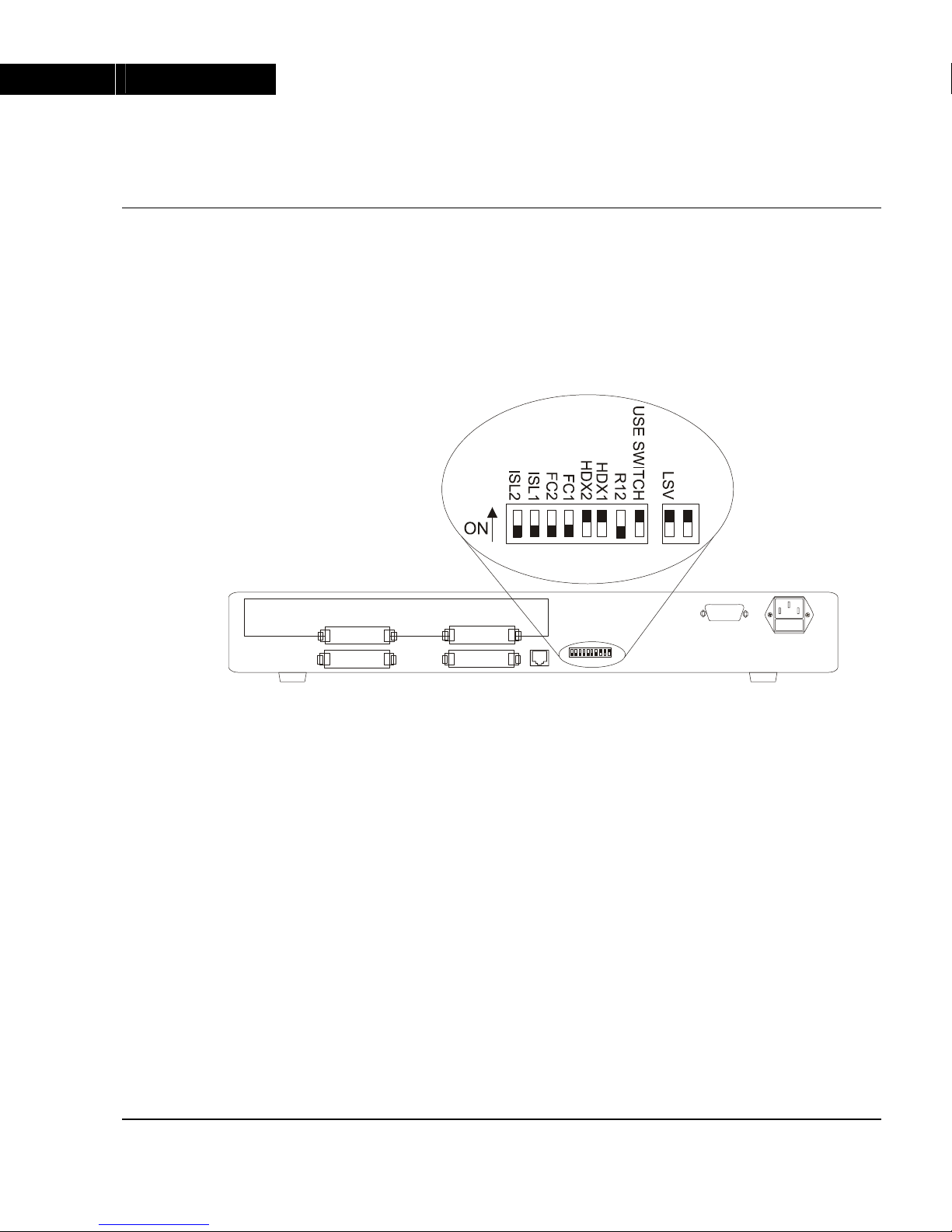
The drawing below shows the default positions of the DIP switches on the rear
panel of the switch.
Figure 1 The P113F Stackable Switch Rear Panel Showing the DIP
Switches in their Default Positions
All the DIP switches relate to the two 100 Mbps ports. A detailed explanation of
the DIP switches follows.
The DIP switches described below function only when the USE SWITCHES
switch is in the ON position.
• LSV – Latest Software Version: The agent can use either the latest downloaded
software (the “Application” version), or a “Basic” version.
• USE SWITCHES: Selects whether the 100Mbps functions will be controlled by
the DIP switches or from the management station.
When set to ON, 100 Mbps switch settings are determined by the DIP switches,
and can only be monitored, but not changed, by the console.
When set to OFF, the DIP switch settings are ignored and the 100 Mbps port
functionality is controlled from the console via the P110 NMA.
Set to ON when you don’t have SNMP management, or when you want to
ensure that the settings will not be changed.
• R12 – Redundancy: Setting this switch to ON enables redundancy. In this case,
port 1 is active and port 2 is redundant. In the event of link failure, switchover
to port 2 is automatic. Where redundancy is not desired, set this switch to OFF,
and both ports will operate normally.
P113F Stackable Switch Installation Guide 5

Chapter 2 Installation
• HDX – Full/Half Duplex (HDX1 is for port 1 and HDX2 is for port 2):
When this switch is in the ON position, the switch operates in Half Duplex
mode. When the switch is in the OFF position, the switch operates in Full
Duplex mode. Full Duplex gives a throughput of 200 Mbps. In Full Duplex
mode no repeaters are allowed in the path. Half duplex operation gives a
throughput of 100 Mbps.
The stack must be Reset after changing Half/Full Duplex mode.
• FC – Flow Control (FC1 is for port 1 and FC2 is for port 2):
When this switch is in the ON position, the switch uses a proprietary Avaya
mechanism to prevent packet loss on the link due to congestion in full-duplex
mode.
• ISL –Inter Switch Link Tagging (ISL1 is for port 1 and ISL2 is for port 2):
ISL Tagging expands Virtual LANs and Priority across the backbone. This
switch should be set to ON when you wish to make two Avaya switches
linked by the P113F act as a single logical entity. When set to OFF ports will
send standards based Fast Ethernet 100BASE-X packets.
If the settings of an existing P110 stack are changed, the stack must be reset. Press
and hold both buttons on the front panel simultaneously for a second or more to
reset the entire P110 stack. In a reset, all LED indicators turn on. Pressing reset does
not affect configuration settings.
Once you have set the switches, you may proceed with the physical installation of
the switch.
6 P113F Stackable Switch Installation Guide
Chapter 2 Installation
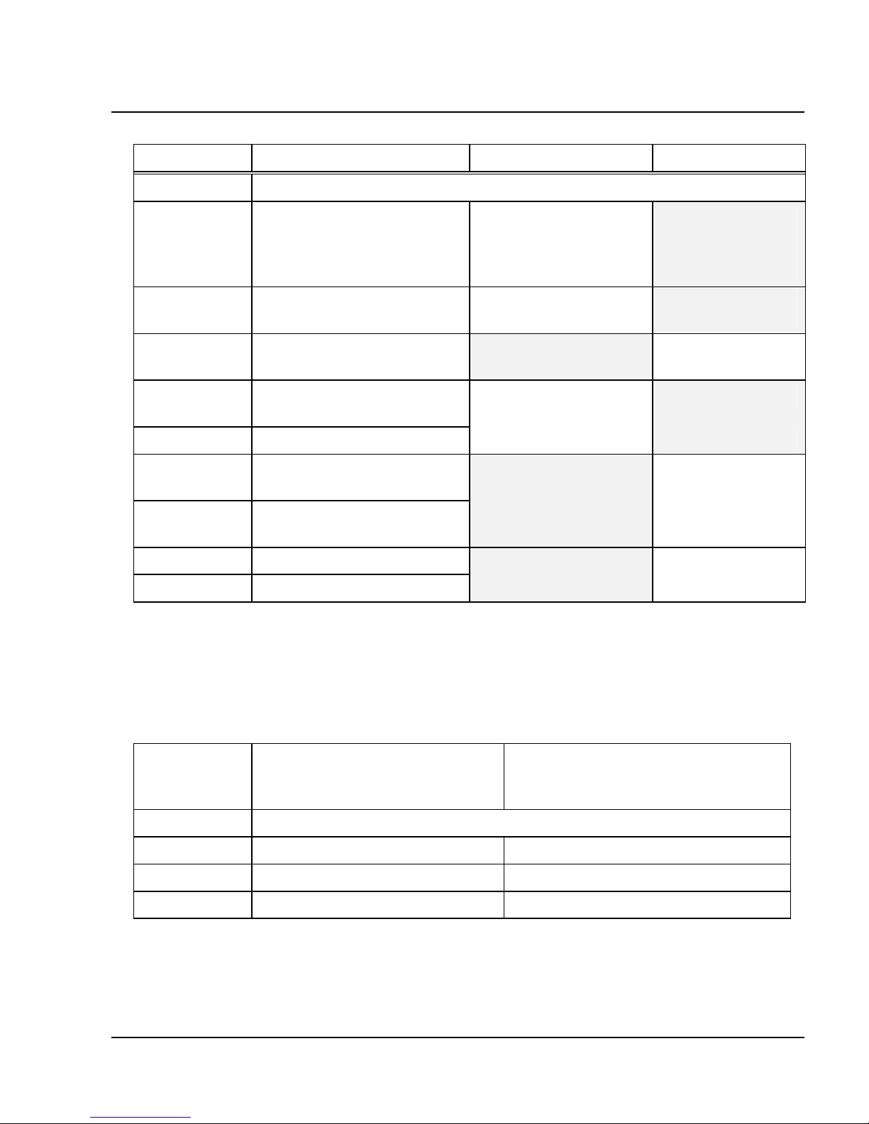
Table 1 DIP Switches on the P113F Stackable Switch
Switch Function Down (OFF) UP (ON)
Reserved for Future Use
LSV Latest software version. Use the “Basic”
software version in
Bank A
Use the latest
“Application”
agent software in
Bank B (Default)
USE
SWITCH
Selection of operational
mode
Ignore switches. Use
management settings
Use switches
(Default)
R12 Redundancy (ports 1 and
2)
Disable Enable.
FDX1 Full or Half Duplex , port
1
Full Duplex. Half Duplex.
FDX2 Full or Half Duplex, port 2 (Default)
FC1 Flow control, port 1
Reserved for Future Use
Not active. Active.
FC2 Flow control, port 2
Reserved for Future Use
ISL1 ISL Tagging, port1 Not active Active
ISL2 ISL Tagging, port 2
Configuring the Module for Common Applications
The table below describes how to set the DIP switches for common applications of
the P113F.
Table 2 DIP Switch Settings for Common Configurations
Switch Configuration 1:
Backbone link to Ava
y
a products
(LEB-200 or P113F)
Configuration 2:
Backbone link to non-Avaya
products
R12 Set according to the application
FDX ON (at both ends of link) According to other side of link
FC ON (at both ends of link) OFF
ISL ON (at both ends of link) OFF
P113F Stackable Switch Installation Guide 7

Chapter 2 Installation
Installing the P113F Stackable Switch
The procedure for getting the P113F Stackable Switch up and running depends on
whether the switch is to operate standalone or as part of a stack.
First, attach the adhesive rubber legs to the base of the switch. If the switch is to be
rack mounted, do not attach the legs.
Standalone Operation - Plug ‘n’ Play
Getting the switch working is quick and easy:
1. Connect the power cable to the switch,
2. Connect the cables to the front panel ports,
The switch is now fully operational. By default, all ports will operate in half
duplex mode.
To ensure proper ventilation, ensure that the P110 NMA slot is closed.
The P113F contains an on-board agent. If you want to upgrade the on-board
software to a higher version, see the Software Download section on page 15.
Stacking Operation
To make the P113F work as part of a stack (and to give SNMP management
capabilities to a single P113F), a P110 NMA with the correct software version is
required. See the P113F Stackable Switch Release Notes for the required version.
To check what software version you have, see the agent configuration window in
CajunView, or see the setup main menu of the P110 NMA.
1. Before adding a switch to the P110 stack, turn off the main power to the stack,
by individually switching off each hub
2. Place the P110 NMA in the top switch of the stack
3. If the P110 NMA and the P113F on-board agent contain the latest software
version, go to step 5.
4. If the P110 NMA does not contain the latest agent software, you should
perform a software download of the latest version. The software is on the
diskette that came with the P113F. Download is performed via TFTP using a
Terminal console or via the timed Download application from your
management station– details can be found in the P110 NMA installation
Guide. (The download procedure itself is the same as that described in the
Software Download section on page 20).
If the P113F on-board agent does not contain the latest version, perform the
download as described in Software Download to the On-Board Agent on
page 15.
5. Place the P113F switch in the stack. The P110 NMA must be in the top switch
of the stack.
To ensure proper ventilation, ensure that all empty P110 NMA slots in the
stack are closed.
8 P113F Stackable Switch Installation Guide
Chapter 2 Installation
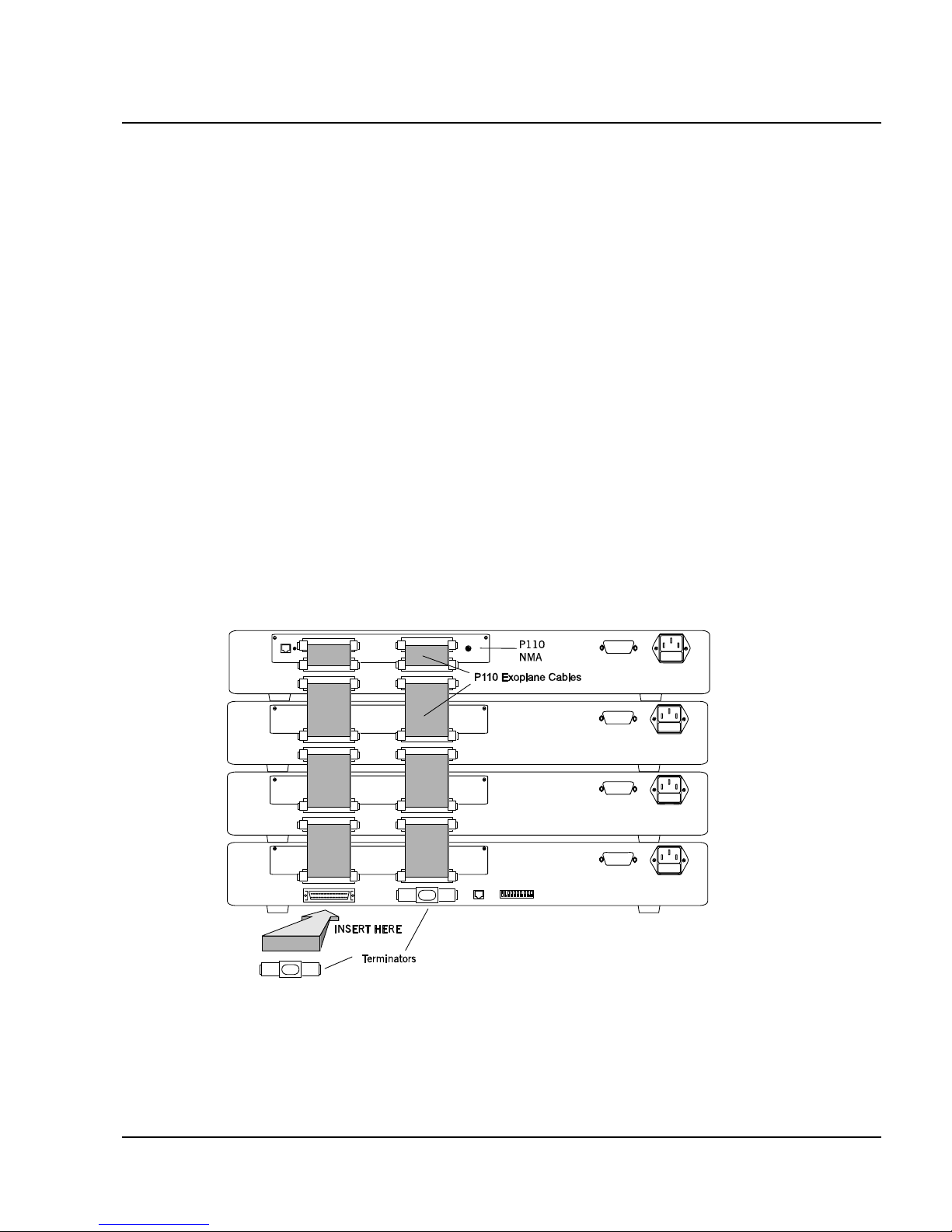
6. Connect switches using the P110 Exoplane cables, as shown in Figure 2. A
switch connects to its upper neighbor through two Exoplane cables, and to its
lower neighbor through another two Exoplane cables. Make sure you securely
fasten the cables to the connectors.
Cabling Requirements:
• For correct operation, the P110 Exoplane must be fully connected, with all
units powered up. In case units are stacked, the P110 NMA must be installed
and connected to the Exoplane.
Failure to observe this requirement will cause the units to block all traffic on
attached stations and segments.
• When using the P114T or P114F in the stack, make sure all switches in the
stack are connected using P110 Exoplane cables (part number 108362203, with
white connectors and marked C/S:B) of the type supplied with the new
switch. Extra cables can be ordered from your local Avaya representative.
• For proper operation of the 100BASE-FX ports, the standard requires 62.5µ
Multimode fiber-optic cables.
Figure 2 Rear view of a P110 switch stack, showing how the switches are linked via
the P110 Exoplane cables. A P110 NMA resides in the uppermost
switch.
7. Two terminators are supplied with the P110 NMA. Insert the two terminators
into the lowest two connectors at the bottom of the stack, as shown in Figure 2.
8. Turn on the mains power to the stack, by individually switching on each hub.
9. Connect the cables to the front panel ports,
P113F Stackable Switch Installation Guide 9

Chapter 2 Installation
If both the P113F and the P110 NMA in the stack contain the latest software
version (as specified in the P113F Stackable Switch Release Note) or higher, the
stack is now fully operational
When a new version of agent software becomes available, you should perform
software download to benefit from the extra capabilities provided. See
Software Download on page 15.
10 P113F Stackable Switch Installation Guide
 Loading...