

Avaya Outdoor Antenna Installation Manual

Table of Contents
1 Welcome 1-1
About This Guide 1-1
■ Who Should Use This Guide 1-1
■ Finding Additional Information 1-2
About Avaya Wireless Outdoor Router 1-4
2 Preparing for Installation 2-1
Site Prerequisites 2-1
Overview of the Indoor Installation 2-2
■ Outdoor Router Hardware 2-2
■ Cable System 2-6
Overview of the Outdoor Installation 2-9
■ Antenna Placement 2-9
■ Antenna Mast/Wall Bracket 2-12
■ Grounding System 2-13
■ Antenna Cable Routing 2-15
Before Climbing the Roof... 2-16
3 Determine Range & Clearance 3-1
Introduction 3-1
Determine the Outdoor Range 3-2
■ Determine the Maximum Range 3-3
■ Determine the Cable Factor 3-7
■ Determine the Clearance Factor 3-8
Avaya Outdoor Antenna Installation Guide i

Examples 3-13
■ Point-to-Point Links 3-13
■ Point-to-Multi Poi nt Lin ks 3-15
4 Installing the Antenna 4-1
Planning Antenna Installation 4-1
■ Safety Precautions 4-1
■ Installation Overview 4-3
Mounting the Antenna 4-5
Connecting the Antenna Cable 4-6
■ Sealing the Cable Connectors 4-7
A The Antenna Cabling System A-1
The Outdoor Cabling Components A-1
■ Selecting the Correct Connector-Type A-1
Avaya Wireless Cable Assembly A-4
Avaya Wireless Surge Arrester A-5
Low-Loss Antenna Cable A-7
B 14 dBi Directional Antenna B-1
General Description B-1
■ Contents of the Antenna Box B-1
■ Mounting the Directional Antenna B-1
C 7 dBi Omni-Directional Base Station Antenna C-1
Hardware Specifications C-1
■ Mounting the Omni-directional Antenna C-1
ii Avaya Outdoor Antenna Installation Guide

D 10 dBi Omni-Directional Base Station Antenna D-1
Hardware Specifications D-1
■ Mounting Instructions D-1
E 12 dBi Directional Wide Angle Antenna E-1
Hardware Specifications E-1
■ Mounting Instructions E-1
F 24 dBi Directional Parabolic Grid Antenna F-1
Hardware Specifications F-1
■ Kit Contents F-2
■ Assembling the Antenna F-2
■ Mounting the Antenna F-4
Avaya Outdoor Antenna Installation Guide iii

G Certified Outdoor Solutions G-1
Introduction G-1
Selecting the Right Card & Cables G-3
Regulatory Information G-7
H Support & Warranty H-1
Technical Support H-1
Warranty and Repair H-2
List of Figures LOF-1
Index 1-1
List of Tables LOT-1

Welcome
About This Guide
This Avaya Outdoor Antenn a In stallat io n G uide explains how to ins tall and setup an outdoor antenna installation based on Avaya Wireles s PC Cards that will
be used in combination with:
■ Avaya Wireless Outdoor Router products
■ Avaya Wireless Client product s
There is also a chapter about verifying the wireless link qua lity and correcting
problems that mig ht arise during installation or operation.
This guide does not explain how to erect an t enna masts, or how to install a
safety grounding s ystem. Thes e are pre-re quisites th at must be in place before
the directional antenna is installed.
1
1
Who Should Use This Guide
The installation of Outdoor Ante nna Links requires technical expertise. At th e
very least, you should be able to:
■ Install and conf igure the ne t w ork components, such as the Outdo orRouter
and the Avaya Wireless LAN adm i n is trat or’s station.
■ Understand or have a wo r king knowledge of the in stall at ion pr oc edures for
network operating systems under Microsoft Windows 95/98 and/or Microsoft
Windows NT.
■ Mount the outdoor antenna and surge arrester. Avaya Inc. recommends that
the installation is perfo rm ed by a qualified anten na installation service .
1 Formerly also referred to as WavePOINT-II PTP, W aveACCESS Link WP-II or WaveCAMPUS.
Avaya Outdoor Antenna Installation Guide 1-1

Welcome
About This Guide
!
DANGER:
The Avaya Wireless Outdoor Router outd oor ant ennas are intend ed f or
mounting on a ro of, or t he side of a building. Installat ion shall not be
attempted by som eone who is not train ed or ex perienced in this typ e of
work.The antenna has to be installed by a suitably trained profes si onal
installation technician or a qualified antenna installation service. The site
pre-requisites have to be checked by a person familiar with the national
electrical code, and other regulations governing this type of installation.
Finding Additional Information
Installing Outdoor Router Hardware
Avaya Wireless outdoor an te nna installations are typ ic al ly connected to
Outdoor Router devices. The hardware installation of these devices is described
in the Getting Started Guide that is included with each Outdoor Rout er uni t .
Configuration and Management
The configuration and management of outdoor antenna links is controlled via the
OR Manager progr am ; an M S - W in dows based applic at io n th at can be installed
on almost any computer running Windows 95, 98 or Windows NT (v4.0).
How to install this pro gra m is described in the Getting Started Guide th at is
included with each Outdoor Router unit.
How to use the O R Manager program is de scr i bed in:
■ The “Context-Sensitive Help” as de sc ribed below.
■ The "Avaya Wireless OR Manager - User’s Guide" provided on the software
CD-ROM that cam e wi t h th e O utdo or Rout er dev i ce ( in serted inside the
back-side cover o f the G etting Started Guide that came with yo ur product).
■ The "Avaya Wireless OR M anager - User’s Guide" also descr ib es how to
monitor the perfor m ance of your wireless net w or k, and provides hints and
scenarios for troubl eshooting perfor m anc e degradation.
To view and/or print these documents, you will need to install the Adobe
Acrobat Reader provided on the software CD-ROM.
1-2 Avaya Outdoor Antenna Installation Guide
Welcome
1
About This Guide
Context-Sensitive Help
Context-sensitive help for the OR Manager program is avail abl e b y cl i cking the
“Help” button on th e screen or pressing the function key.
F
Hardware Specifications
■ Outdoor Router hardware specifications are described in the Getting Started
Guide that is shippe d w i th eac h device.
■ Radio Frequency specifications of the Outdoor Router are described in the
"Avaya Wireless PC Card Getting S tarted".
■ Hardware speci f ic atio ns for the outdoor antennas, the cabling sys t em and
the Avaya Wireless Surge Arre st er are listed in Appendic es of this guide.
Additional files on your Software CD-ROM
All software CD-ROM s (or diskettes) that cam e with your Avaya Wireless
products, include a file c al le d “readme.txt”. This fil e contains information a bout
the software version and/or drivers on the diskette.
NOTE:
You are advised to print an d re ad t he “ re adme.txt” file prior to i nsta lling
your Avaya Wireless products, as it may contain additional information
that was not available when this document was printed.
Other Sources of Information
All documentation listed above can be downloaded from the Avaya Wireless
http://www.avaya.com.
NOTE:
You are advised to visit the website at regular i ntervals for the latest
available inform at ion, documentation and softwar e updates and other
Avaya Wireless news.
Avaya Outdoor Antenna Installation Guide 1-3
Welcome
About Avaya Wir ele ss Outdoor Router
About Avaya Wireless Outdoor Router
The Avaya Wireless O utdo or Rout er enables you to setup a w i re le ss system
that supports:
■ “Avaya Wireless Remote Outdoor Router” functionality, or
■ “Avaya Wireless Central Outdoo r Ro ut er ” functionality.
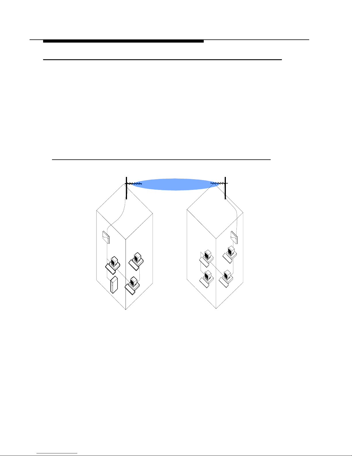
Avaya Wireless Remote Outdoor Router
With two Avaya Wireless Remote Outdoor Routers, it’s easy to setup a wireless
Point-to-Point link as pictured in Figure 1-1 below.
Figure 1-1 Avaya Wireless Point-to-Point Link
The Point-to-Poi nt (PTP) Link functionality enables you to setup a connection
between two lo ca tions as an alternative to:
■ Leased lines in buildi ng-to-building connections, or
■ Wired Ethernet bac kbones between AP IIs in ‘har d- to -w ire’ environments.
1-4 Avaya Outdoor Antenna Installation Guide
Welcome
About Avaya Wir ele ss Outdoor Router
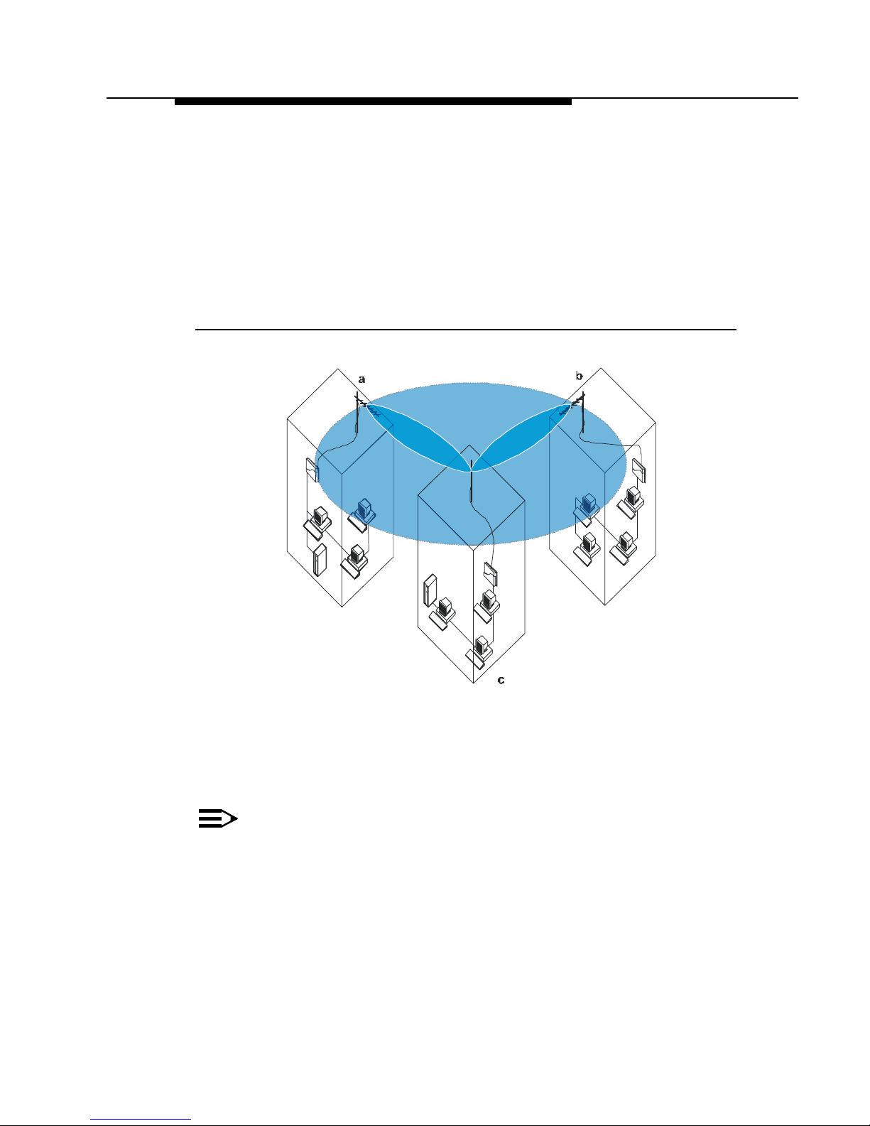
Avaya Wireless Central Outdoor Router
If you wish to conne ct m ore th an t w o buildings, you ca n choose to:
■ Setup multiple Point-to-Point links, using multiple pairs of Remote
Outdoor Router system s, or
■ Setup a single Point -to- Multipoint system using a single Centr al
Outdoor Router and mul tiple Remote Outdoor Router s as pictured in
Figure 1-2 below.
Figure 1-2 Avaya Wireles s Point-to-Multipoint Li nk
Looking at Figure 1-2 the system is designe d as follows:
■ The central building c is equipped with the Central Outdoor Router,
connected to either an omni-direct ional , or wide angle antenna.
■ The two Remote buildings a and b have both been equipped with Remote
Outdoor Routers connect ed to directional an te nnas.
NOTE:
Subject to local radio re gul ations and legislati on, the outdoor antenna
solutions described in this document may not be available in all parts of
the world. Consult Ap pendix G “Certified Outdo or Sol ut ions” for more
information.
Avaya Outdoor Antenna Installation Guide 1-5

Welcome
About Avaya Wir ele ss Outdoor Router
Upgrading the Avaya Wireless Outdoor Router
If you wish to exten d th e f eat ur es of previously pu rc has ed hardware you ca n
purchas e dedicated Software License K i ts to upgr ade:
■ AP II into one of the Avaya Wireless Outdo or Routers described on the
previous pages.
■ Extend the features of a pre viously purchased Avaya Wir el ess
Outdoor Routers.
For more information about the software license upgrade program, please
consult:
■ Your authorized Avaya Wireless Reseller or local Avaya Inc. Sales office for
more information.
■ The Avaya Wireless website at : http://www.avaya.com.
1-6 Avaya Outdoor Antenna Installation Guide

Preparing for Installation
Site Prerequisites
Please review all requirements outlined withi n the sections listed below bef or e
starting the installation proc edure:
■ Overview of the Indoor Installation (page 2-2)
■ Overview of the Outdoor Installation (page 2-9)
■ Before Climbing the Roof... (page 2-16)
Prior to climbing on th e ro of or an y ot her area where you int end to install the
outdoor antenna, you are advised to:
2
■ Verify yo u have arra nged all saf ety measures for ou tdoor/ rooftop installation
(see the “Safety Precautions” on page 4-1).
■ Verify you have all equipment and to ol s re quired to install the outdoor
antennas.
■ Install and verify proper operation of the equip m ent.
Avaya Outdoor Antenna Installation Guide 2-1
Preparing for Installation
Overview of the Indoor Installation
Overview of the Indoor Installation
The indoor installat i on of the l in k w ill consist of the followi ng components:
■ Outdoor Router Hardware, and
■ A Cable System.
Outdoor Router Hardware
There are two types of hardware install at ions to setup a wireles s connection:
■ The Outdoor Router, and
■ The Outdoor Router Client.
Outdoor Router
To setup a point-to-point wireless connection between two Outdoor Routers, you
will need :
■ Two Avaya Wirel ess Outdoor Routers with PC Car d, and
■ Two antenna cable systems (see App endix Appendix A “The Ante nna
Cabling System”), and
■ Two outdoor antenna’s.
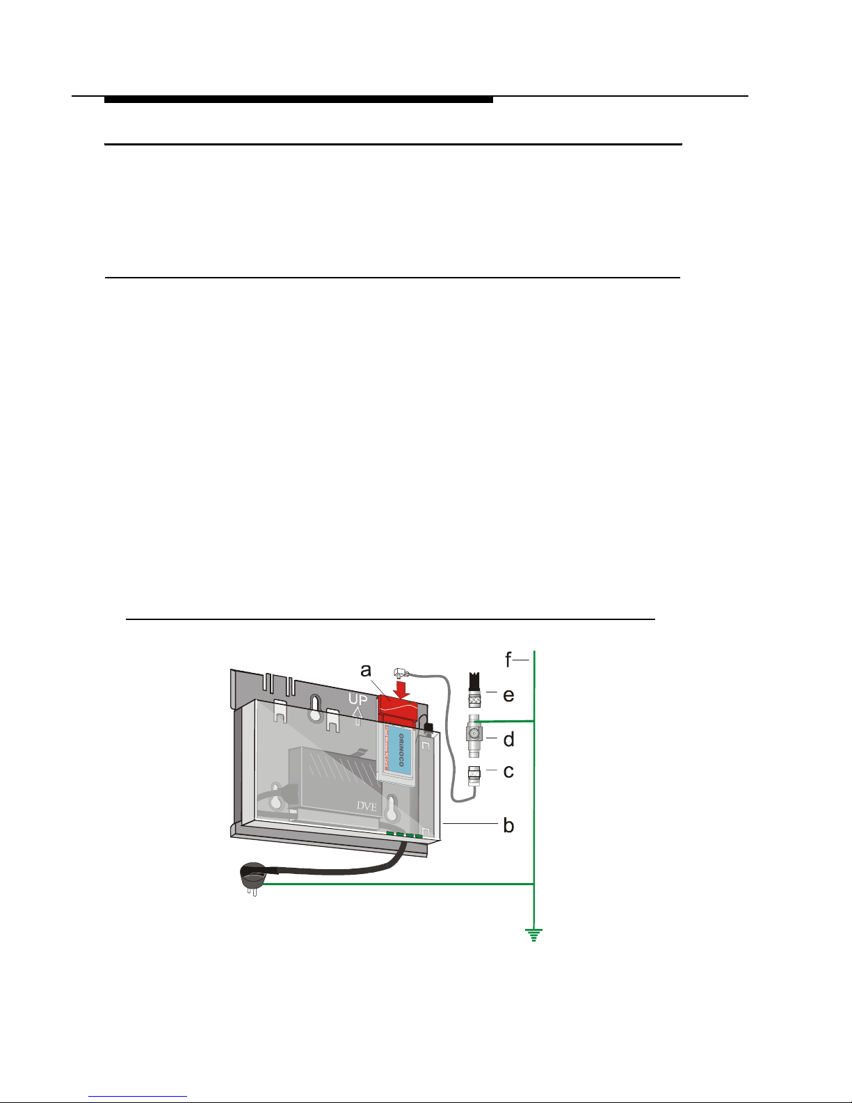
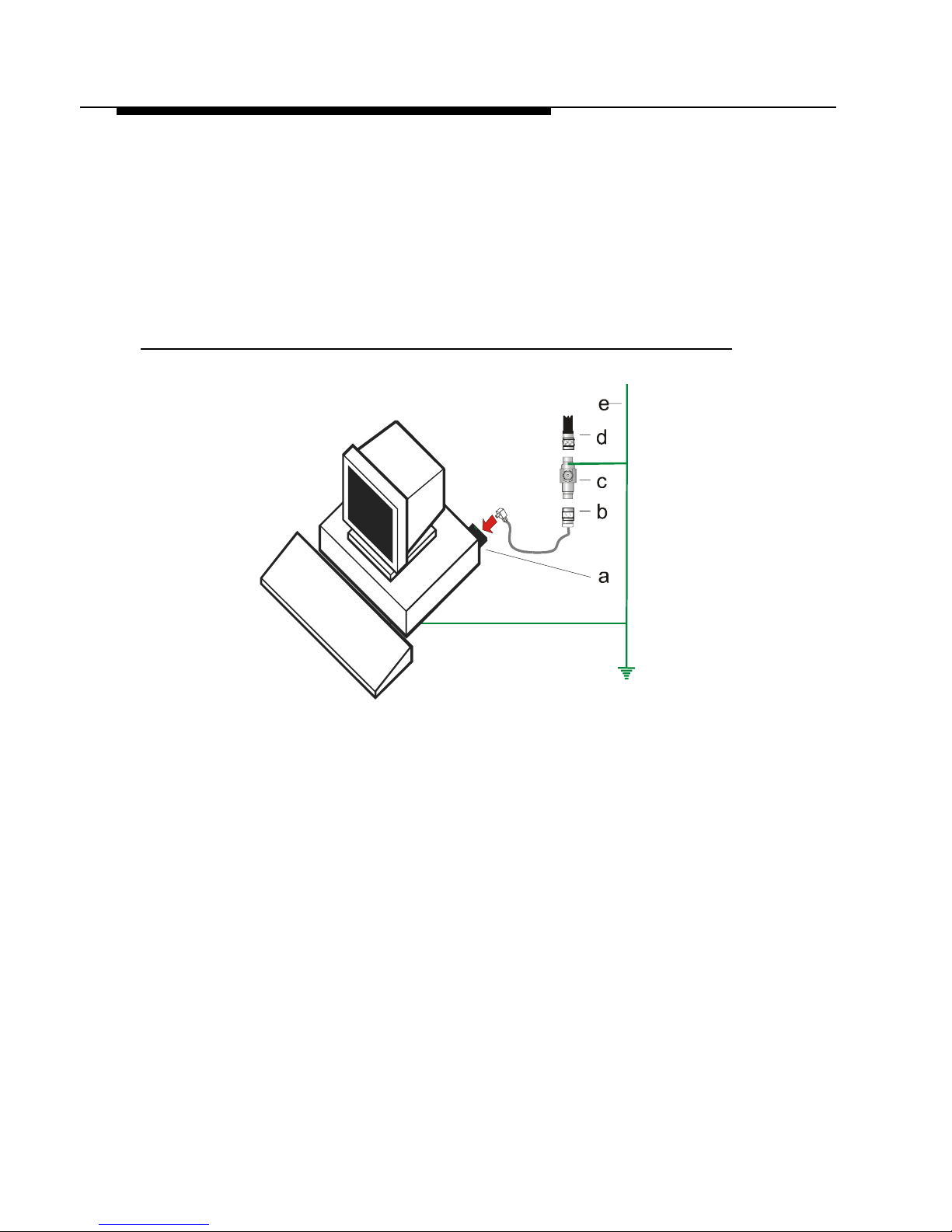
Figure 2-1 shows an ov erview of the hardw ar e set up for this indoor installa tio n.
Figure 2-1 Overview Indoor Installation of the Outdoor Router
2-2 Avaya Outdoor Antenna Installation Guide

Preparing for Installation
Overview of the Indoor Installation
On each end of the wireless link you will need the following items as pictured in
Figure 2-1 on page 2-2:
a. The Avaya Wirel es s PC Card (see “Selecting the R ig ht C ar d & C ables” on
page G-3).
b. The Outdoor R outer device that has been loaded with Avaya Wirele ss
Outdoor Router software.
c. The Cable Assembly to connect the PC Card to the Surge Arrester.
d. A surge arrester to protect your se nsi tiv e Avaya Wi re less equipment from
static discharge and transients that may occur to y our ant enna.
e. A low-loss antenna cable to connect the indoor installation to the outdoor
antenna.
f. A grounding system as described in “Grounding System” on page 2-13.
!
WARNING:
The Avaya Wireless Outdoor Router, the Avaya Wireless Surge Arrester
and the antenna mast must be connec te d to the sa m e gr ounding
system.
Placement of the Outdoor Router Hardware
The hardware of your Avaya Wireless Outdoor Route r de vi ce is designed for
indoor mounting and operation. The ideal location to install your Outdoor Router
unit must satisfy t he following re qui rements:
■ The location provides a connection to a gr ounding type AC wall outlet (100-
240 VAC), using the standard power cord as su ppl i ed with the unit.
The ground of the AC wall outlet must be connected to the same grounding
system as the Avaya Wireles s Surge Arrester and an te nna mast (see
“Grounding System” on page 2-13).
■ The location must al low fo r ea si l y disconnecting the O utdoo r Rout er unit
from the AC wall outlet.
■ The location provides a connection to the network backbone that may either
be:
■ The Ethernet LAN cabl e t hat connects it to a hub, bridge or directly into
a patch panel or
■ The wireless connection via a second Avaya Wir eless PC Card that is
inserted into th e other PC Card slot of th e Outdoor Router device.
■ The location is as close as possible to the point where the antenna cable will
enter the building (see also “Place m ent of the Sur ge Arrester” on page 2-6).
Avaya Outdoor Antenna Installation Guide 2-3
Preparing for Installation
Overview of the Indoor Installation
Outdoor Router Client
To setup a wireless connection with the Outdoor Router Client, you will need:
■ One PC Card,
■ One Outdoor Router Client Li ce nse Kit, and
■ One antenna cabl in g system.
Figure 2-2 shows an ov erview of the hardw ar e set up for this indoor installat io n.
Figure 2-2 Overview Indoor Installation OutdoorRouter Client
On each end of th e w ireless link you will ne ed th e foll ow ing items as pictured in
Figure 2-2:
a. The Avaya Wir eless PC Card (see “Selecti ng t he Ri ght Card & Cables” on
page G-3).
b. The Cable Assembly to connect the Avaya Wireless PC Card (A) to the
Surge Arrester.
c. A surge arrester to protect your sensitive Avaya Wireless equipment from
static discharge and tra nsients that may occu r to your antenna.
d. A low-loss antenna cable to connec t the indoor installation to the outdoor
antenna.
e. A grounding systems as describe d i n “Gr ounding System” on page 2-13.
2-4 Avaya Outdoor Antenna Installation Guide

Preparing for Installation
Overview of the Indoor Installation
!
WARNING:
The Avaya Wireless Outdoor Router, the Avaya Wireless Surge Arrester
and the antenna mast must be connec te d to the sa m e gr ounding
system.
Avaya Outdoor Antenna Installation Guide 2-5

Preparing for Installation
Overview of the Indoor Installation
Cable System
!
CAUTION:
The Outdoor Router products are designed for indoor installation. At all
times the location of th e Outd oor Router unit must be indoors, to pr otect
the unit from extr em e w eather conditions, excessive hea t and humidity
and to keep the unit free from vibration and dust.
Prior to mounting the Outdoor Router products you are advised to carefully
calculate:
■ The distance bet we en t he i n te nded loc a ti on o f yo ur Out d oo r Router unit and
the location of the antenna mast, and
■ The height of the antenna on the mast.
If the low-loss an t enna cable is not long enou gh to cover this distance you can
select from the fo llowing two options:
■ Select another cabl e length from the Avaya Inc. low-loss cable offering (see
Appendix A “The Antenna Ca bli ng System”), or
■ Select another location that satisfies the requirements listed on the previous
page to mount your Outdoo r Rout er device.
As the length of the ant enna cable may affect the act ual range of your outdoor
antenna installation, the second one is t he pr ef er r ed option.
!
WARNING:
You are not allowed to change the length of the Avaya Inc. low-loss
antenna cable. Shortening the cable will void the Avaya Inc. Warranty,
and may conflict w ith rad io cer t ifi cati ons and/or approv al s.
How to install the Outdoor Router hardware is described in the Getting Started
Guide that was ship p ed with the Outdoor Route r de vi ce.
Placement of the Surge Arrester
The Avaya Wireless Surge Arrester is an indispensable part of your ou tdoor
antenna installation, to protect your sen si t iv e electronic equipment from
transients or electro- stati c di s charges at the antenna.
2-6 Avaya Outdoor Antenna Installation Guide

Preparing for Installation
Overview of the Indoor Installation
For optimal protecti on the Avaya Wirel es s Surge Arrester must be in stalled at a
location that satisfies the following requirements:
■ A location as close to the location where the antenna cable will enter the
building (see also “Pl acement of the Outdoo r Rout er Ha rd w ar e” on
page 2-3).
■ The location allows for easily (dis-)connecting the surge arrester from/to the
Avaya Wireless PC Card in the Avaya Wirel es s O utdo or Rout er using the
Cables Assembly pictured in Figure 2-1 on page 2-2.
■ The location provi des a connection to th e same grounding system as the
Outdoor Router unit and the outdo or ant enna mast as descr ibed in
“Grounding System” on page 2-13.
Antenna Cable Route
The antenna cable m ust be connected to the O utdoor Router unit via the
Avaya Wireless Surge Arrester and Cable Assembly as pictured in Figure 2-1 on
page 2-2. To plan the route of the antenna cable please consid er the following:
■ Does the cable rout e r equire drilling through a wall or ceiling?
■ Do you have a build ing pl an of the desired locat i on s how i ng any other
existing cabling ro ut es like electricity, telephone or networking?
■ Does the type of buil di ng m at erials require spec ia l too ls fo r dri lling
purposes?
The cable should no t be ins talled i nt o “ti ght” positions, as be nding or applying
excessi v e f or ce t o th e c onn ec to rs ma y da ma ge th e an te n na c ab le . A lwa ys a ll ow
the cable to bend na tu ra lly a round corners. The re commended bend radius is
100 mm (4 in.).
The antenna cable must be secured along its complete length. No part of the
antenna cable sho ul d be allowed to hang fre e. Thi s is partic ul ar ly important for
cable parts that are installed outdoo rs .
Avaya Outdoor Antenna Installation Guide 2-7

Preparing for Installation
Overview of the Indoor Installation
!
CAUTION:
The antenna cab l e and cable connect ors ar e not designed to withstand
excessive for ce:
a. Do not use the connectors as “cable gr ips” to pu ll ca bl e t hr ough
raceway or conduit.
b. Do not use the cable connect or to support t he weight of th e cable
during or after installation.
c. Do not use any appliances to tighten the connectors.
d. Always seal the connectors using w eather-proofing tape.
Prior to sealing the outdoor connectors and permanently securing the
cable to the wall using cable ties and wall hooks, you may wish to verify
if the installation and all components function properly.
2-8 Avaya Outdoor Antenna Installation Guide
Preparing for Installation
Overview of the Outdoor Installation
Overview of the Outdoor Installation
The outdoor installation of the link (point-to-point or point-to-multipoint) will
consist of the follo wi ng components:
■ The Avaya Inc. Antenna
■ The Avaya Inc. proprietary low- lo ss ant enna cable (availa bl e in di fferent
cable lengths).
■ Antenna Mast/Wall Bracket for the antenna.
■ An adequate “Grounding System” th at me ets the r equirements describe d i n
“Grounding System” on page 2-13.
NOTE:
All outdoor cable connectors must be sealed with the enclosed weatherproofing stretch tape to permanently wa te rp ro of the coax connectors.
!
DANGER:
For your own safety, the antenna mast and th e gr ounding system
should be installed only by experienced install at ion pr of essionals who
are familiar with loc al bui l di ng and safety codes and/or the national
electrical codes .
Carefully read the instructions as described for the “Grounding System”
on page 2-13 and verify that your in stallat i on complies with the
appropriate regul at i on s and codes before in stall ing t he antenna.
Antenna Placement
To achieve maximum perfor m ance for your wirele ss ou tdoo r connection, the
Avaya Wireless Outdoor Antenna must have clear line-of-sight. Line-of-sight can
be defined as:
■ No obstacles in the dir ect path bet ween the two antennas.
■ No obstacles within a def i ned zone around the ant enna beam.
You need to be aware that the shape of a radio beam is not straight and narrow
like a laser beam. The r adio beam, also refer r ed t o as F re snel Zone
“bulged” in the midd le , like f or example a “rugby ball”. The exact shape and
width of the Fresnel Zone is determined by the path length and frequency of the
radio signal.
1
, is rather
1 Pronounced as “Fray-Nell”
Avaya Outdoor Antenna Installation Guide 2-9
Preparing for Installation
Overview of the Outdoor Installation
If any significant part o f th is zone is obs tructed, a portion of the radio energy will
be lost, re sult ing in reduce d perfor mance. Reduce d perf ormanc e may also occur
when obstacles tha t a re c lo se to t he antenna beam cause signal reflecti ons or
noise th at i nterfere with the ra di o signal.
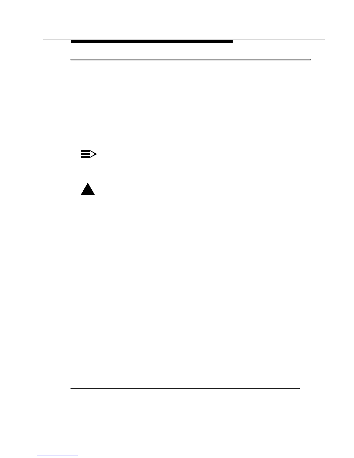
Figure 2-3 shows som e t ypical examples of o bstacl es t hat you must avoid for
the Directional Ant enna to operate effectively:
a. Neighboring Buildings
b. Trees or other obstruct i ons
c. Power lines
To allow optimal performance you will need to ensure that the type and
placement of the antennas leaves sufficient clearance of the Fresnel Zone at the
maximum width of th e bulge, typically a t the m id-point between the antennas.
For more information turn to Chapter 3 “Determine Range & Clearance”.
Figure 2-3 Potential Obstacles for a Directional Antenna
2-10 Avaya Outdoor Antenna Installation Guide

Preparing for Installation
Overview of the Outdoor Installation
To minimize the influen ce of obstacles, signal interference or reflections plea se
note the following guidelines:
■ Mount the antenna as high as possible above the “ground” to all ow
maximum clearanc e :
■ In open areas “grou nd” is th e actual surface of the ear th
■ In dense urban areas “g ro und” is to be interpreted as the height of the
highest obstacle in the signal path between the t w o ant enna sites.
■ Avoid trees in the signal path to avoid signal absorption due to dynamic
changes in seas ons (leaves/ice).
■ Install the antenna at least 2 m (6 ft) away from all other antennas.
Other situations where reflections of the radio signal may cause interference are
environments where l ar ge reflecting surfaces exist in parallel or partly
perpendicular to the antenna beam.
Environments with lar ge r ef lect i ve surfaces includ e:
■ Mirrored-glass buildings
■ Crowded parking lots
■ Water or moist earth and moist vegetation
■ Above ground power/telephone lines
Weather conditions suc h as r ain or snow usually will not have much impact on
the performance of your Avaya Wireless Outdoor Syst em, provided tha t yo u
sealed all cable connectors using the weather-proofing tape.
Seasonal factors t hat could have an effect on signal propagation may occur in
the following situations:
■ A marginal communications quality in late fall (with no leaves on trees in the
signal path) might fail in the summer.
■ In winter, an antenna link may fail whe n th e antenna is expose d to ic e
buildup, or when the ant en na el em ents are covered with snow.
NOTE:
Radio paths over water or ext re m el y f la t ground may require
optimization of ante nna height at one end of the path. This is due to
reflections adding in-phase or out-of-phase. Adjustment of antenna
height by 1 to 3 meters should move the sig nal from a null to a peak.
In these cases consult your supplier to take appropriate steps to ma in tain or
optimize wireless per f or mance.
Avaya Outdoor Antenna Installation Guide 2-11

Preparing for Installation
Overview of the Outdoor Installation
Antenna Mast/Wall Bracket
Basically ther e ar e two ways to erect an an te nna mast:
■ “Tripod Mou nt”
■ “Wall (Side ) Mount”
Tripod Mount
The tripod mou nt is used primarily on peak ed and f l at roo fs . The antenna mast
must be secu re d to th e ro of using 3 or 4 guy wires that ar e equally spaced
around the mast. When the heigh t of t he antenna mast is m or e th an 3 meters
(10 ft), you are advised to use at least three guy wir es f or each 3 meter (10 ft)
section of the mast.
Wall (S ide) Mount
A wall (side) mou nt allo w s fo r mounting an antenna (mast) on the side of a
building or on the side of an elevator penthouse. This will provide a convenient
mounting location when the roof overhang is not excessive and/or the location is
high enough to pr ovi de a clear line of sight.
In most situations mounting an antenna directly to the wall will not allow you to
properly align the ant enna with the corres ponding antenna at th e opposite end
of your wireless link. As poor alignment will typically result in poor performance,
Avaya Inc. advises you to always mount the an te nnas to a mast.
Antenna Mast Requirements
To accommodate the Avaya Wireless antennas, th e an te nna mast must satisfy
the following requirements:
a. The const ru ctio n of th e m ast must be of a sturdy, weatherproof and non-
corrosive material like for example galvanized or stainless steel construction
pipe.
b. Typical diameter of the mast should be between 35 mm (1.4 in.) and 41 mm
(1.625 in.). Subject to th e type of antenna that you intend to install other
diameters may be possible as well.
c. The height of the antenna mast must be sufficient to allow the antenna to be
installed at least 1.5 m (5 ft.) above the peak of roof. If the roof is metal, then
the height of the antenna should be a minimum of 3 m (10 ft) abo ve the roof
(see also Chapter 3 “Determ i ne Range & Clearance”).
d. The mast or wall-bracket mu st be free f r om any substance that may pre vent
a good electrical connection with the an te nna; for example, paint.
2-12 Avaya Outdoor Antenna Installation Guide

Preparing for Installation
Overview of the Outdoor Installation
Grounding System
Direct grounding of th e antenna mast, Avaya Wireless Outdoor Router bridge
and Avaya Wireless Surge Arres t er is ve ry important.
A safety gr ou ndi ng sy st em is n eces s ar y to pr ot ec t y our A vay a Wireless O ut d oo r
installation from ligh tn in g st r ike s a nd t he build-up of static electricity.
!
WARNING:
The antenna mast, Avaya Wireless Outdoor Router and Avaya Wireless
Surge Arrester mus t be connected to the sam e gr ound, using an
equipotential bondi ng conductor.
A good electrical connection should be m ade to one or more grou nd
rods, using at least a 10AWG ground wire and non-corrosive hardware.
The grounding syst em m ust comply with the Nat i onal Electrical Code
and safety standards th at apply in your countr y. Always check with a
qualified electrician if you are in doubt as to whet her your
Avaya Wireless Outdoor installation is properly grounded.
Antenna Alignment
For optimal perfor m anc e of your wireless link, make sure that the antennas are
properly aligne d ( f acing one an other “eye- to-eye” ) . To align the antennas:
■ Use a pair of binoculars and/or a map of the area and compass to point the
antennas to one another.
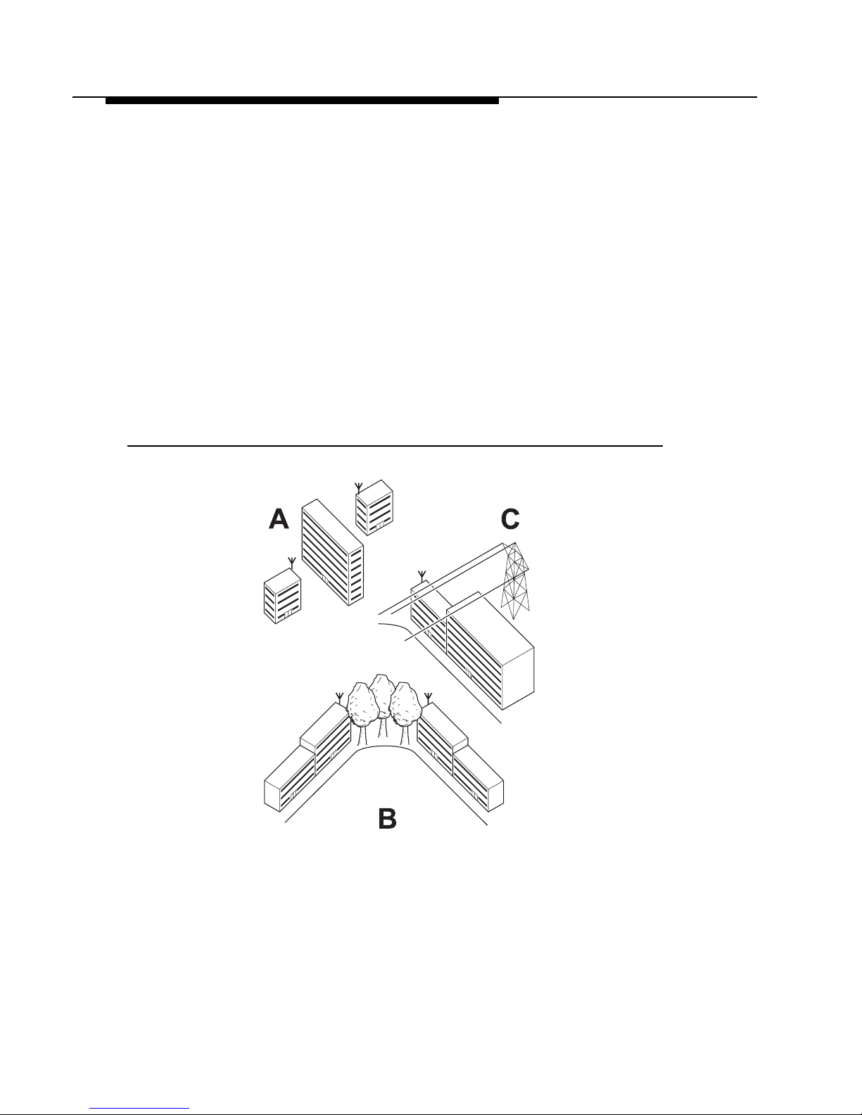
■ Use the Wireles s Link Test option of the OR Manager as de scribed in the
"Avaya Wireless OR Ma nager - User’s Guide" to analyze t he r adi o l ink
quality.
The Wireless Link Test option will enable you to displ ay the strength of the
Avaya Wireless radio signal related to the noise that may be appear in the
signal path.
Looking at the Wir el ess Link Test screen, you can in te ra ct iv el y op t imi ze
antenna alignment if required, by making small modifi ca tions in the antenna
orientation.
■ Alternatively, consult a professional Antenna Installation Servi ce to optimize
the antenna alignm ent.
Omni-directional antennas are char acterized by a wide ra di at i on patte rn.
Therefore alignment of this type of antennas is less critical than for directional
antennas.
Avaya Outdoor Antenna Installation Guide 2-13
Preparing for Installation
Overview of the Outdoor Installation
Figure 2-4 OR Manage r Wireless Li nk Test
Antenna Polarization
The standard mounting method for Avaya Inc. outdoor antennas is designed for
vertical polarizatio n.
In some cases you might consider mounting the an te nn a fo r horizontal
polarization . Fo r ex am pl e to m ini m i ze t he influence of cross- talk be tween
antennas when:
■ You plan to mount multiple d irec tional antennas to th e same mast.
■ Your wireless link “cross es” another radio beam fr om a neighboring
installation.
Mounting for ho rizontal polarization is onl y supported by the Avaya Inc. 14 dBi
Directional Antenna and 24 dBi Directional Parabolic Grid Antenna.
NOTE:
For optimal wir eless performance you must always v eri fy t hat t he
polarization o n both ends of the wireles s link is the same for both
antennas.
Consult the corresponding appendices for instructions on alternating the
antenna polarization.
2-14 Avaya Outdoor Antenna Installation Guide

Preparing for Installation
Overview of the Outdoor Installation
Antenna Cable Routing
The antenna cable must be routed and fixed in such a way to clear the passage
area for installation te ch ni ci ans.
All connectors that ar e located outdoors, mu st have a weatherproof seal. You
are advised to seal connectors only after you have completed fin a l radio tests.
Avaya Outdoor Antenna Installation Guide 2-15

Before Climbing the Roof...
Before you start ins talla tion check whether you have all hardwa re components
required to setu p an outdoor antenna link. For each side of a wireless outdoor
antenna link yo u w ill need:
1. One Outdoor Router or Outdoor Router Client.
2. One Avaya Wireless PC Card.
3. One Avaya Wireless C abl e Assembly (to conn ec t ite m 2 to item 4) .
4. One Avaya Wireless Sur ge Arrester.
5. One Avaya Inc. low-l os s ant enna cable.
6. One Avaya Wireless O utdoor An te nna
7. Weather-proofing electrical tape.
If any of the items is mis sing, or if there are si gns of shipme nt damage, please
inform your supplier.

Determine Range &
Clearance
Introduction
When you read abo ut w irel e ss outdoor products, you wi ll often en counter the
terms “output pow er ” of th e ra di o and “gain” of the anten na equipment as
measures for the “s t re ngt h” of the transmitted signal .
■ Output Power of radio equipment is often subject to maximum limits as
defined by local radi o re gulations (see Appendix G “Certified Ou tdoor
Solutions”). Consequently Output Power is not by definition th e w ay to
enhance wireless performance.
■ High gain antenna s are larger in size than low gai n antennas, and are
charac t erized by a nar row “focus” of the radio beam. These two
characteristi cs m ake it more difficult to aim th e antennas, and/or adjust
antenna alignment to optimize the performance of the wireless point-to-point
link.
3
The Avaya Inc. outdoor solution is based upon the following principles:
■ An output power and antenna gain that com ply with the maximum lim its as
defined by local gov er ni ng bodies concern in g ra di o t ra nsm i ssions.
■ Enhanced radio sensitivity for optimal re cei ve quality of Avaya Wireless
radio signals transmitted by remot e ant ennas.
Avaya Outdoor Antenna Installation Guide 3-1

Determine Range & Clearance
Determine the Outdoor Range
Determine the Outdoor Range
The range of yo ur o utdoo r an t enna installation is closel y r el ated to a number of
different factors. To allow you to de te rm i ne th e range of the Avaya Wireless
Outdoor Router antenna system in your situation, we have de fine d t he f or m ul a
listed below:
Range = Maximum Range x Cable Factor x Clearance Factor
■ Maximum Range identifies the theoretical maxim um t hat could be achieved
under optimal circu mstances using the available Avaya Wireless Outdoo r
products according to the i r sp ecs and in complian ce w i t h lo cal radio
regulations.
This value can be read from Table 3-1 or Table 3-2, according to the country
where the antenna system will be installed.
■ Cable Factor identifies a correctiv e percentage value that com pensates
additional cable loss related to the type of cables applied at both ends of the
wireless link. The Cable Factor value can be read from Table 3-3 on
page 3-7.
■ Clearance Factor identifies a correctiv e percentage value that should be
applied in case the signal path of your wireles s link does not provide t he
minimum clearan ce l i sted in the Maximum R an ge tab le . Th e C lear ance
Factor can be read from Fi gure 3-2 on page 3-11.
An example on how t o use this formula is described in the “Example s ” on
page 3-13.
!
CAUTION:
This formula sho ul d only be used as a rule of thu m b t o ass es the
possibl e range tha t could be ac hieved in your situa t ion, and/or to select
the type and height of the antenna instal l ations. Always perform on-si te
measurements to validate the resul ts from th e ra nge calculation. To
perform such measurements you can use the OR Manager Wirel ess
Link test option as described in the "Avaya Wi re l ess OR Manager User’s Guide".
3-2 Avaya Outdoor Antenna Installation Guide

Determine Range & Clearance
Determine the Outdoor Range
Determine the Maximum Range
The maximum range of your Avaya Wireless Outdoor Router antenna system is
based on the:
■ Type of Outdoor Antenna Equipment (page 3-3)
■ Data Speed of the Wireless Link (page 3-7)
■ Clearance of the Sig nal Path (see “Determine the C l ear ance Factor” on
page 3-8).
NOTE:
The valu es listed in t his section are based upon calculations that
assume “optimal radio conditions”.
They do not represen t a guar antee that the same maximum distance
can be achieved at your location. Different pe rf or m ance figures may
result from:
■ I nc or re ct al ignm ent of antennas (see “An te nna Alignment” on
page 2-13).
■ Polarization mism atch of the antenna s.
■ Sources of interference or unexpected reflections in the signal path
that affect the comm unications quality (s ee “Antenna Placem ent”
on page 2-9).
■ Severe weathe r co nditions such as heav y rain or snow fall, or
strong winds.
■ Seasonal influe nces such as leaves on trees, or icing on the
antennas.
Type of Outdoor Antenna Equipment
As described in the pr evious chapters, Avaya Inc. offers differen t typ es of
outdoor antennas, and cable lengths to design your Avaya Wireless
Outdoor Router outdoor anten na i nstallation.
■ The directional an tennas provide max imum range, but due to t hei r nar ro w
signal beam width, the se antennas requi re pre ci se a nt enna alignment to
achieve optimal performance. The higher the antenna gain the more precise
the alignment sh oul d be .
Directional ant ennas are typically us ed t o connect:
— Two Remote Outdoor Routers in a Point-to-Point link.
— One Remote Outdoor Router (satel l ite) to one Central Outdoor Router
(base) in a Point-to-Multipoint link.
Avaya Outdoor Antenna Installation Guide 3-3

Determine Range & Clearance
Determine the Outdoor Range
■ The omni-directio nal antennas, have by nat ur e an omni directional az im u th
pattern which make s th es e ant ennas easy to install. T her e i s also a gain
beam width relation for om ni - antennas: the high er the gai n of th e om niantenna the narrower the vertical beam width. In a hilly terrain a 7dBi omni
antenna can/will be a better solution then the 10 dBi omni-antenna.
■ The 12 dBi wide-angle antenna is a good solu tion for the Central
Outdoor Router (base) antenna in hilly terrain. It combines a wide opening
angle with relative high gain. The mountin g brackets allow tilting of the
antenna.
For beamwidth and gain characteristics of the various antennas, please
consult the appendices of this document that describe each antenna in more
detail.
The length of the ante nna cable also has an impact on the m aximum range that
can be achieve d wi th th e ant e nna combination (see “Determine the Cable
Factor” on page 3-7).
Subject to local rad io re gulat i ons that in a number of co unt r ie s l imit th e
maximum ou tp ut power, Avaya Inc . offers differen t ou tdoo r an te nna products in
the various countries over the world. Therefore you will need to consult the table
that matches th e ra di o re gulations as apply in your country:
■ Tab le 3-1 on page 3-5 , for the U SA and Canada and any ot her country that
adheres to the radio reg ul at io ns as defined by the US Fed er al
Communications Commission (FCC).
■ Tab le 3-2 on page 3-6 , for all Eur opean countries, Japan, and any other
country that adhere s t o th e ra di o r egulations as define d by t he European
Telec ommunication s Standards Institut e (ETSI) and MPT.
3-4 Avaya Outdoor Antenna Installation Guide
 Loading...