

Avaya one-X Deskphone Edition Installation And Maintenance Manual

Avaya one-X™ Deskphone Edition
for 9600 Series SIP IP Telephones
Installation and Maintenance Guide
Release 2.0
16-601943
December 2007
Issue 2

© 2007 Avaya Inc.
All Rights Reserved.
Notice
While reasonable efforts were made to ensure that the infor mation in this
document was complete and accurate at the time of printing, Avaya Inc. can
assume no liability for any errors. Changes and corrections to the information
in this document may be incorporated in future releases.
For full legal page information, please see the complete document, A vaya
Legal Page for Hardware Documentation, Document number 03-600759.
To locate this document on our Web site, simply go to
http://www.avaya.com/support
the search box.
Documentation disclaimer
Avaya Inc. is not responsible for any modifications, addition s, or deletions to
the original published version of this documentation unless such modifications,
additions, or deletions were performed by Avaya. Customer and/or End User
agree to indemnify and hold harmless Avaya, Avaya's agents, servants and
employees against all claims, lawsuits, demands and judgments arising out of,
or in connection with, subsequent modifications, additions or deletions to this
documentation to the extent made by the Customer or End User.
Link disclaimer
Avaya Inc. is not responsible for the contents or reliability of any linked Web
sites referenced elsewhere within this documentation, and Avaya does not
necessarily endorse the products, services, or informa tion described or o ff ered
within them. We cannot guarantee that these links will work all of the time and
we have no control over the availability of the linked pages.
Warranty
Avaya Inc. provides a limited warranty on this product. Refer to your sales
agreement to establish the terms of the limited warran ty. In addition, Avaya’s
standard warranty language, as well as information regarding support for this
product, while under warranty, is available through the following Web site:
http://www.avaya.com/support
Copyright
Except where expressly stated otherwise, the Product is protected by copyrigh t
and other laws respecting proprietary rights. Unauthorized reproduction,
transfer, and or use can be a criminal, as well as a civil, offense un der the
applicable law.
Avaya support
Avaya provides a telephone number for you to use to report pro blems or t o ask
questions about your product. The support telephone number
is 1-800-242-2121 in the United States. For additional support telephone
numbers, see the Avaya Web site:
http://www.avaya.com/support
Software License
USE OR INSTALLATION OF THE PRODUCT INDICATES THE END USER’S
ACCEPTANCE OF THE TERMS SET FORTH HEREIN AND THE GENERAL
LICENSE TERMS AVAIL ABLE ON T HE AVAYA WEBSITE AT
http://support.avaya.com/LicenseInfo/
YOU DO NOT WISH TO BE BOUND BY THESE TERMS, YOU MUST
RETURN THE PRODUCT(S) TO THE POINT OF PURCHASE WITHIN TEN
(10) DAYS OF DELIVERY FOR A REFUND OR CREDIT.
Avaya grants End User a license within the scope of the license types
described below. The applicable number of licenses and units of capacity for
which the license is granted will be one (1), unless a different number of
licenses or units of capacity is specified in the Documentation or other
materials available to End User. “Designated Processor” means a single
stand-alone computing device. “Server” means a Designated Processor that
hosts a software application to be accessed by multiple users. “Soft w are”
means the computer programs in object code, originally licensed by Avaya and
ultimately utilized by End User, whether as stand-alone Products or
pre-installed on Hardware. “Hardware” means the standard hardware
Products, originally sold by Avaya and ultimately utili zed by End User.
License Type(s):
Designated System(s) License (DS). End User may install and use each copy
of the Software on only one Designated Processor, unless a different number
of Designated Processors is indicated in the Documentation or other mat erials
available to End User. Avaya may require the Designated Processor(s) to be
identified by type, serial number, feature key, location or other specific
designation, or to be provided by End User to Avaya through elect roni c mean s
established by Avaya specifically for this purpose.
and search for the document number in
(“GENERAL LICENSE TERMS”). IF
Third-party Components
Certain software programs or portions thereof included in the Product may
contain software distributed under third party agreements (“Third Party
Components”), which may contain terms that expand or limit rights to use
certain portions of the Product (“Third Party Terms”). Information identifying
Third Party Components and the Third Party Terms that apply to them is
available on Avaya’s Web site at:
http://support.avaya.com/ThirdPartyLicense/
Interference
Using a cell, mobile, or GSM telephone, or a two-way radio in close proximity to
an Avaya IP Telephone might cause interference.

Contents
Chapter 1: Introduction . . . . . . . . . . . . . . . . . . . . . . . . . . . 5
About This Guide . . . . . . . . . . . . . . . . . . . . . . . . . . . . . . . . . . . 5
Intended Audience. . . . . . . . . . . . . . . . . . . . . . . . . . . . . . . . . . . 5
Document Organization . . . . . . . . . . . . . . . . . . . . . . . . . . . . . . . . 6
Issue Date . . . . . . . . . . . . . . . . . . . . . . . . . . . . . . . . . . . . . . . 6
What’s New in This Release. . . . . . . . . . . . . . . . . . . . . . . . . . . . . . 6
Online Documentation. . . . . . . . . . . . . . . . . . . . . . . . . . . . . . . . . 9
Customer Support . . . . . . . . . . . . . . . . . . . . . . . . . . . . . . . . . . . 10
Chapter 2: 9600 Series SIP IP Telephone Installation. . . . . . . . . . . 11
Introduction . . . . . . . . . . . . . . . . . . . . . . . . . . . . . . . . . . . . . . 11
IP Telephone Models . . . . . . . . . . . . . . . . . . . . . . . . . . . . . . . 11
Software . . . . . . . . . . . . . . . . . . . . . . . . . . . . . . . . . . . . . . 12
Pre-Installation Checklist . . . . . . . . . . . . . . . . . . . . . . . . . . . . . . . 12
Converting Software on 9600 Series IP Telephones. . . . . . . . . . . . . . . . . 14
Converting 9600 Series IP Telephones. . . . . . . . . . . . . . . . . . . . . . 15
Assembling the 9600 Series SIP IP Telephone . . . . . . . . . . . . . . . . . . . 17
Powering the 9600 Series IP Telephone . . . . . . . . . . . . . . . . . . . . . 17
Dynamic Addressing Process/Telephone Startup. . . . . . . . . . . . . . . . . . 21
Chapter 3: Local Administrative Options . . . . . . . . . . . . . . . . . 27
Introduction . . . . . . . . . . . . . . . . . . . . . . . . . . . . . . . . . . . . . . 27
Accessing Local (Craft) Procedures . . . . . . . . . . . . . . . . . . . . . . . . . 28
Entering Data for Administrative Options . . . . . . . . . . . . . . . . . . . . . . 29
About Local Administrative Procedures . . . . . . . . . . . . . . . . . . . . . . . 29
Setting the 802.1X Operational Mode. . . . . . . . . . . . . . . . . . . . . . . . . 31
Pre-Installation Checklist for Static Addressing. . . . . . . . . . . . . . . . . . . 31
Static Addressing Installation. . . . . . . . . . . . . . . . . . . . . . . . . . . . . 32
Disable/Enable Automatic Gain Control . . . . . . . . . . . . . . . . . . . . . . . 34
Clear Procedure . . . . . . . . . . . . . . . . . . . . . . . . . . . . . . . . . . . . 34
Disable/Enable Debug Mode . . . . . . . . . . . . . . . . . . . . . . . . . . . . . 35
Group Identifier . . . . . . . . . . . . . . . . . . . . . . . . . . . . . . . . . . . . 36
Interface Control. . . . . . . . . . . . . . . . . . . . . . . . . . . . . . . . . . . . 37
Disable/Enable Event Logging . . . . . . . . . . . . . . . . . . . . . . . . . . . . 38
Logout . . . . . . . . . . . . . . . . . . . . . . . . . . . . . . . . . . . . . . . . . 39
Reset System Values . . . . . . . . . . . . . . . . . . . . . . . . . . . . . . . . . 39
Restart the Telephone . . . . . . . . . . . . . . . . . . . . . . . . . . . . . . . . . 40
Issue 2 December 2007 3

Contents
Signaling Protocol Identifier . . . . . . . . . . . . . . . . . . . . . . . . . . . . . 40
Configuring SIP Settings . . . . . . . . . . . . . . . . . . . . . . . . . . . . . . . 42
Configuring Time Server Settings . . . . . . . . . . . . . . . . . . . . . . . . . . 43
Site-Specific Option Number Setting. . . . . . . . . . . . . . . . . . . . . . . . . 43
The View Administrative Option . . . . . . . . . . . . . . . . . . . . . . . . . . . 44
Chapter 4: Maintaining 9600 Series SIP IP Telephones. . . . . . . . . . 47
Introduction . . . . . . . . . . . . . . . . . . . . . . . . . . . . . . . . . . . . . . 47
Downloading Software Upgrades. . . . . . . . . . . . . . . . . . . . . . . . . . . 47
Download Procedure . . . . . . . . . . . . . . . . . . . . . . . . . . . . . . . 48
Updating the Settings File. . . . . . . . . . . . . . . . . . . . . . . . . . . . . 49
Downloading Language Files. . . . . . . . . . . . . . . . . . . . . . . . . . . 49
The GROUP System Value . . . . . . . . . . . . . . . . . . . . . . . . . . . . . . 50
Chapter 5: Troubleshooting Guidelines . . . . . . . . . . . . . . . . . . 51
Introduction . . . . . . . . . . . . . . . . . . . . . . . . . . . . . . . . . . . . . . 51
Error Conditions . . . . . . . . . . . . . . . . . . . . . . . . . . . . . . . . . . . . 51
DTMF Tones . . . . . . . . . . . . . . . . . . . . . . . . . . . . . . . . . . . . 52
Power Interruption. . . . . . . . . . . . . . . . . . . . . . . . . . . . . . . . . 52
Installation Error and Status Messages . . . . . . . . . . . . . . . . . . . . . . . 52
Operational Errors and Status Messages . . . . . . . . . . . . . . . . . . . . . . 54
Appendix A: Restart Scenarios. . . . . . . . . . . . . . . . . . . . . . . 59
Scenarios for the Restart Process . . . . . . . . . . . . . . . . . . . . . . . . . . 59
Restart the Telephone. . . . . . . . . . . . . . . . . . . . . . . . . . . . . . . 59
Boot File Needs to be Upgraded . . . . . . . . . . . . . . . . . . . . . . . . . 60
Latest Boot File Loaded/No Application File or
Application File Needs to be Upgraded. . . . . . . . . . . . . . . . . . . . . 64
Latest Boot File and System-Specific
Application File Already Loaded . . . . . . . . . . . . . . . . . . . . . . . . 65
Appendix B: Glossary of Terms . . . . . . . . . . . . . . . . . . . . . . 67
Terms Used in This Guide. . . . . . . . . . . . . . . . . . . . . . . . . . . . . . . 67
Appendix C: Related Documentation . . . . . . . . . . . . . . . . . . . 71
IETF Documents . . . . . . . . . . . . . . . . . . . . . . . . . . . . . . . . . . 71
ITU Documents. . . . . . . . . . . . . . . . . . . . . . . . . . . . . . . . . . . 71
ISO/IEC, ANSI/IEEE Documents . . . . . . . . . . . . . . . . . . . . . . . . . 71
Index . . . . . . . . . . . . . . . . . . . . . . . . . . . . . . . . . . 73
4 9600 Series SIP IP Telephones Release 2.0 Installation and Maintenance Guide

Chapter 1: Introduction
About This Guide
This guide describes how to install and maintain the 9600 Series IP Telephones in a Session
Initiation Protocol (SIP) environment.
The 9600 Series IP Telephones product line supports two signaling protocols, the Session
Initiation Protocol (SIP) and the H.323 protocol. Both of the following must be installed to use
9600 Series IP Telephones with the SIP protocol:
● Avaya Communication Manager Release 4.0 and greater, and
● SIP Enablement Session (SES) software Release 4.0 and greater.
Note:
Note: Any reference to HTTP in this guide applies equally to HTTPS.
When running the 9600 Series IP Telephones in an H.323 environment see the
Avaya one-X™ Deskphone Edition for 9600 Series IP Telephones Installation
and Maintenance Guide for installation and maintenance information.
This document does not cover administration for Avaya Distributed Office. Full
documentation for Avaya Distributed Office is available on the Avaya support
Web site, www.avaya.com/support
Intended Audience
This document is intended for personnel who install and administer the 9600 Series SIP IP
Telephones.
!
CAUTION:
CAUTION: Avaya does not provide product support for many of the products mentioned in
this document. Take care to ensure that there is adequate technical support
available for the servers involved, including, but not necessarily limited to, HTTP,
HTTPS, and DHCP servers. If the servers are not functioning correctly, the IP
telephones might not be able to operate correctly.
.
Issue 2 December 2007 5

Introduction
Document Organization
The guide contains the following sections:
Chapter 1:
Chapter 2: 9600 Series SIP
IP Telephone Installation
Chapter 3:
Administrative Options
Chapter 4: Maintaining
9600 Series SIP IP
Telephones
Chapter 5:
Guidelines
Appendix A: Restart
Scenarios
Appendix B:
Terms
Appendix C: Related
Documentation
Introduction Provides an overview of this guide.
Local
Troubleshooting
Glossary of
Describes the equipment and resources required to properly
install and operate the 9600 Series SIP IP Telephones. Provides
instructions on installing the telephones out of the box.
Describes how to set local administrative options, if requested by
the system or LAN administrator.
Describes maintenance actions like downloading telephone
software from the Avaya support Web site and customizing
system values.
Describes error conditions and messages that might occur
during the installation of the 9600 Series SIP IP Telephones.
Explains the different scenarios possible for the sequence o f the
restart process.
Provides a glossary of terms used in this document or which are
generally applicable to 9600 Series SIP IP Telephones.
Provides references to external documents that relate to
telephony in general.
Issue Date
This is the second release of this document, issued in December , 2007. This document was first
issued in May, 2007.
What’s New in This Release
New material in this issue to support SIP Release 2.0 software includes:
New GigE Models Support SIP - This release extends SIP capability to two additional
telephones, the 9630G and 9640G. Both models provide Gigabyte Ethernet (GigE) support, but
are otherwise identical to their 9630 and 9640 SIP IP telephone counterparts.
6 9600 Series SIP IP Telephones Release 2.0 Installation and Maintenance Guide

What’s New in This Release
Language Support - 9600 Series SIP IP Telephones now support 13 languages. See
"Language Selection" in the Avaya one-X™ Deskphone Edition for 9600 Series SIP IP
Telephones Administrator Guide for more information.
Emergency Button - Administrators can now program an “Emergency” number using the new
PHERERGNUM parameter. Users can then dial the pre-assigned emergency number whether
or not they are logged into the telephone they are using t o make the call. For more information,
see "Emergency Number Administration" in the Avaya one-X™ Deskphone Edition for 9600
Series SIP IP Telephones Administrator Guide.
Administration Enhancements - SIP Software Release 1.1 supports functionality introduced
on Avaya Communication Manager Release 4.1 and SIP Enablement Services (SES) Release
4.1.
Visiting User Support - Visiting user support allows end users to move easily between
geographic locations while retaining their telephone extension and settings. 9600 Series SIP IP
Telephones can be provisioned through the settings file VU_MODE configuration parameter to
one of three modes:
● No Visiting User - the telephone operates “normally” and has no user interface impact for
normal operation. The telephone can be forced to a “registered Inactive” state when a
visiting user registers elsewhere.
● Optional Visiting User - the telephone prompts the user at registration time if they are
visiting or not.
● Forced Visiting User - the telephone allows only visiting user registrations.
For more information, see "Visiting User Administration" in the Av aya one-X™ Deskphone
Edition for 9600 Series SIP IP Telephones Administrator Guide.
Link Layer Discovery Protocol (LLDP) - 9600 Series SIP IP Telephones now support link
layer discovery protocol. See the Avaya one-X™ Deskphone Edition for 9600 Series SIP IP
Telephones Administrator Guide for information.
802.1X - 9600 Series SIP IP Telephones now support IEEE standard 802.1X for increased
security. The new configuration parameter DOT1X defines the 802.1X operational mode. The
new parameter DOT1XSTAT enables/disables 802.1X. The new parameter DOT1XEAPS
specifies the authentication method to use with 802.1X. These parameters can be set through
the settings file or on a per-phone basis using a local Craft procedure.
WML Browser - 9600 SIP IP Telephones now support WML applications. See Chapter 9 in the
Avaya one-X™ Deskphone Edition for 9600 Series SIP IP Telephones Administrator Guide for
more information.
Issue 2 December 2007 7

Introduction
New, Revised, and Deleted Configuration Parameters - The following configuration
parameters have been added for this release:
● CALL_TRANSFER_MODE
● CALLFWDADDR
● CALLFWDDELAY
● CALLFWDSTAT
● CNAPORT
● CNASRVR
● CONFIG_SERVER_SECURE_MODE
● COVERAGEADDR
● DIALPLAN
● DOT1X
● DOT1XEAPS
● DOT1XSTAT
● ENABLE_AVAYA_ENVIRONMENT
● INTER_DIGIT_TIMEOUT (replaces INTER_DIGIT_DIALING_TIMEOUT_DURATION)
● LAST_LOGIN_STATUS (system-set only)
● LLDP_ENABLE
● MWISRVR
● NO_DIGITS_ENTERED_TIMEOUT_DURATION
● PHNEMERGNUM
● PHNNUMOFSA
● POE_CONS_SUPPORT
● PRESENCE_SERVER
● PROVIDE_EDITED_DIALING
● PROVIDE_EXCHANGE_CALENDAR
● PROVIDE_EXCHANGE_CONTACTS
● QKLOGINSTAT
● RTCPMON
● RTCPMONPORT
● SIP_MODE
● SIPCONFERENCECONTINUE
● TLSSRVRID
● VU_MODE
● VU_TIMER
● WMLEXCEPT
● WMLHOME
● WMLIDLETIME
● WMLIDLEURI
● WMLPORT
● WMLPROXY
8 9600 Series SIP IP Telephones Release 2.0 Installation and Maintenance Guide

Online Documentation
The following configuration parameters have been modified or renamed:
● Parameters PHYxDUPLEX and PHYxSPEED were combined. PHY1SPEED has been
renamed to PHY1_OPERATIONAL_MODE. This parameter now includes the current
duplex mode. PHY2SPEED has been renamed to PHY2_OPERATIONAL_MODE. This
parameter now includes the current duplex mode.
● The OUTBOUND_SUBSCRIPTION_REQUEST_DURATION default value has been
changed to 86400 seconds. This parameter can now be set through the settings file.
● The dimensions for SNTP_SYNC_INTERVAL and
SNTP_SYNC_RANDOMIZATION_INTERVAL have changed from seconds to minutes.
● EXCHANGE_CONTACTS_ENABLED has been renamed to
USE_EXCHANGE_CONTACTS.
● EXCHANGE_CALENDAR_ENABLED has been renamed to
USE_EXCHANGE_CALENDAR.
● The default value definition of ENABLE_G726 has changed.
● The default values and sidetone definitions of the audio parameters AUDIOSTHD and
AUDIOSTHS have been modified.
● WAIT_FOR_REGISTRATION_TIMER can now be set through the settings file.
The following configuration parameters are no longer valid and have been removed:
● PHY1DUPLEX
● PHY2DUPLEX
● INTER_DIGIT_DIALING_TIMEOUT_DURATION
Online Documentation
See the Avaya support site at http://www.avaya.com/support for 9600 Series SIP IP Telephone
technical and end user documentation.
See Appendix C: Related Documentation
such as those published by the Internet Engineering Task Force (IETF) and the International
Telecommunication Union (ITU).
for Web sites that list related, non-Avaya docu ments,
Issue 2 December 2007 9

Introduction
Customer Support
For 9600 Series SIP IP Telephone support, call the Avaya support number provided to you by
your Avaya representative or Avaya reseller.
Information about Avaya products can be obtained at the following URL:
http://www.avaya.com/support
10 9600 Series SIP IP Telephones Re le as e 2. 0 In st al la tio n and M ain t ena nc e Gui d e

Chapter 2: 9600 Series SIP IP Telephone Installation
Introduction
The 9600 Series SIP IP Telephones use Internet Protocol (IP) technology with Ethernet
interfaces. The IP telephones supplement the existing Avaya IP Solutions platform.
The 9600 Series SIP IP Telephones support DHCP and HTTP/HTTPS over IPv4/UDP which
enhance the administration and servicing of the telephones. These telephones use DHCP to
obtain dynamic IP Addresses and HTTP or HTTPS to download new software versions or
customized settings for the telephones.
All 9600 Series SIP IP Telephones provide the ability to have one IP connection on the desktop
for both a telephone set and a PC using an Ethernet switch.
In compliance with Australian law, the following information is provided:
This equipment shall be installed and maintained by trained service personnel. All the input/
output ports are classified as Safety Extra Low Voltage (SELV, in the meaning of IEC
60950). To maintain safety compliance when connecting the equipment electrically to other
equipment, the interconnecting circuits shall be selected to provide continued conformance
of clause 2.3 for SEL V circuits (gene rally, double/reinforced insulation to 240V a c rms to any
primary/mains circuitry and 120Vac rms to any telecommunications network circuitry). To
ensure that these conditions are adhered to, interconnect the equipment only with the
already approved/certified equipment.
IP Telephone Models
There are five telephone set models currently defined in the 9600 Series SIP IP Telephone
family:
● 9620 9630G 9640G
● 9630 9640
The telephones have an internal Ethernet switch that allows the telephone and a PC to share
the same LAN connection, if appropriate. Thus, 9600 models do not need, or work with, the 30 A
switched hub interface. Telephone models appended with "G" have a gigabit Ethernet (GigE)
interface, which speeds data transmission.
This document describes the installation of these telephones and post-installation main tenance
issues. For details about using the features provided by the telephones, see the user
documentation for each telephone. For information about desk or wall mounting any of the 9600
Issue 2 December 2007 11

9600 Series SIP IP Telephone Installation
Series SIP IP Telephones, see the instructions boxed with the telephone. Wall or desk mount
instructions are also available on the Avaya support Web site http://www.avaya.com/support
Software
The 9600 Series IP Telephones ship from the factory set to the H.323 protocol. To run the
telephones in a SIP environment, you must convert the telephone(s) to SIP settings. Further, a
factory-shipped 9600 Series IP Telephone will not contain the most up-to-date software for
registration and SIP operation. When the telephone is first plugged in, a software download
from an HTTP server might be initiated. The software download gives the telephone upgraded
H.323 functionality, however, you must still download the latest SIP software bundle for
telephones to be converted to SIP, then convert applicable telephones to run SIP software, as
described in Converting Software on 9600 Series IP Telephones
For subsequent downloads of software upgrades, SIP Enablement Services (SES) provides the
capability for a remote reboot of the IP telephone. As a consequence of restarting, the
telephone automatically downloads new software if it is available. Chapter 4:
Series SIP IP Telephones covers downloading new software releases.
.
on page 14.
Maintaining 9600
Pre-Installation Checklist
Before plugging in the 9600 Series IP Telephones, verify that all the following requirements are
met. Failure to do so prevents the telephones from working properly and can have a negative
impact on the network. Print copies of this checklist for each server and IP telephone.
Verify These Network Requirements
1. Ensure that the LAN uses Ethernet Category 5e cabling running the IPv4 version of
Internet Protocol.
2. Ensure that the following is installed and/or set up and operative:
● Avaya Communication Manager (CM) Release 4.0 or greater.
● SIP Enablement Services 4.0 or greater. 9600 Series SIP IP Telephones with
SIP Release 2.0 software running on SES 4.0 servers have only those features
compatible with that server.
● NTP Time Server.
!
Important:
Important: The above must be configured properly to support SIP. The CM
Outboard Proxy SIP (OPS) Station Form must be completed to
enable SIP prior to plugging in the telephones. For information, see
Supporting SIP Phones in Communication Manager 4.0 (Document
Number 555-245-206, Issue 7, April, 2007).
12 9600 Series SIP IP Telephones Re le as e 2. 0 In st al la tio n and M ain t ena nc e Gui d e

Pre-Installation Checklist
Verify These Network Requirements (continued)
3. The following circuit packs are installed on the switch:
● TN2602 IP Media Processor circuit pack. Sites with a TN2302 IP Media
Processor circuit pack are strongly encouraged to install a TN2602 circuit p ack
to benefit from increased capacity.
● TN799B, C, or D Control-LAN (C-LAN) circuit pack.
!
Important:
Important: IP telephone firmware requires TN799C V3 or greater C-LAN circuit
pack(s). For more information, see the Communication Manager
Software and Firmware Compatibility Matrix on the Avaya support
Web si te h
ttp://www.avaya.com/support.
4. The Communication Manager (CM) call server is configured correctly , a s described in
the Avaya one-X™ Deskphone Edition for 9600 Series SIP IP Telephones
Administrator Guide and Avaya Communication Manager documentation. Both
documents are available at h
ttp://www.avaya.com/support.
5. The DHCP server and application are administered as described in the Avaya
one-X™ Deskphone Edition for 9600 Series SIP IP Telephones Administrator Guide.
6. The HTTP server and application are administered as described in the Avaya
one-X™ Deskphone Edition for 9600 Series SIP IP Telephones Administrator Guide.
7. The SIP upgrade script and application files from the Avaya Support Web site,
http://www.avaya.com/support
, are loaded correctly on the HTTP/HTTPS server.
8. If applicable, the Voice Mail server is administered as described in the Av aya one-X™
Deskphone Edition for 9600 Series SIP IP Telephones Administrator Guide.
Notes:
- Any or all of the server applications mentioned in items 5-8 can be co-resident on the
same hardware, subject to the specific restrictions of each individual application.
- See the Avaya one-X™ Deskphone Edition for 9600 Series SIP IP Telephones
Administrator Guide for more information about:
● administering other network equipment,
Note:
● administering applications like firewalls, and
● information about topics like port utilization.
Requirements to Verify for Each IP Telephone
9. You have an extension number and an Avaya Co mmunication Manager security code
(password) for each applicable IP telephone.
10. You have an OPTIM extension number and an Avaya Communication Manager
security code (password) for each telephone, and have configured SIP Enablement
Services for each telephone.
11. A Category 5e LAN jack is available at each telephone site.
12. Electrical power is provided to each telephone by a Telephone Power Module (DC
power jack) (must be ordered separately). If the LAN will supply IEEE-standard power
to the telephone, no power module is required.
13. 1 Category 5e modular line cord is available for the connection between the IP
telephone and the PC, if applicable.
Issue 2 December 2007 13

9600 Series SIP IP Telephone Installation
14. Verify that the 9600 Series IP Telephone package includes the following components:
● 1 telephone set with pre-attached stand.
● 1 handset capable of transmitting and receiving 7KHz audio.
● 1 H4DU 9-foot long (when extended) 4-conductor coiled handset cord, plu gged
into the telephone and the handset.
● 1 Category 5e modular line cord for the connection from the IP telephone to the
Ethernet wall jack.
● Avaya one-X™ Deskphone Edition for 9600 Series IP Telephones Safety
Instructions.
● Avaya one-X™ Deskphone Edition for 9600 Series IP Telephones Stand
Instructions.
● Avaya one-X™ Deskphone Edition for 9600 Series IP Telephones Wall Mount
Instructions.
15. IP telephones ship from the factory with H.323 software. Existing installations might
also have many IP telephones running H.323 software. For instructions on how to
convert between H.323 and SIP software, see Converting Software on 9600 Series I P
Telephones.
Note:
Note: For sites using headsets, the 9600 Series SIP IP Telephones support only the
HIS headset cords.
Converting Software on 9600 Series IP Telephones
9600 Series IP Telephones use either H.323 or SIP software but come from the factory with
H.323 software loaded by default. After telephone connection, you should ensure that those
telephones that will run under a SIP protocol are set up properly. This section describes how to
determine what your telephone "environment" is and then convert applicable telephones from
H.323 to SIP software, or from SIP to H.323 software.
There are several H.323 to SIP or SIP to H.323 conversion scenarios, and each scenario
depends on whether the majority of your telephones are H.323 or SIP:
● H.323-Centric - an environment where the majority of IP telephones are and will remain
running H.323 software, but some telephones will become SIP IP telephones. In an
H.323-centric environment, the appropriate H.323 telephone binary files must reside on
the HTTP server and Communication Manager must be configured with the appropriate
H.323 parameters. To convert an individual telephone from H.323 to SIP, both the SIP
Enablement Services (SES) server and Avaya Communication Manager (CM) must be
configured with the appropriate SIP parameters. Any telephone in use prior to conversion
must run Release S1.2 or greater software with a SIG parameter value of “default”
(H.323). See Table 1
instructions.
, the H.323 to SIP and SIP to H.323 Conversion Chart for conversion
14 9600 Series SIP IP Telephones Re le as e 2. 0 In st al la tio n and M ain t ena nc e Gui d e

Converting Software on 9600 Series IP Telephones
● SIP-Centric - an environment where the majority of IP telephones are or will become SIP
telephones running SIP software. In a SIP-centric environment, the 96xxSIP... software
bundle must reside on the HTTP server and both SES and CM must be configured with the
appropriate SIP parameters. To convert an individual telephone from SIP to H.323, Avaya
Communication Manager (CM) must be configured with the appropriate H.323
parameters. Any SIP telephone in use prior to conversion must run Release SIP 1.0 or
greater software with a SIG parameter value of “default” (SIP). See Table 1
, the H.323 to
SIP and SIP to H.323 Conversion Chart for conversion instructions.
What makes an environment H.323- or SIP-centric depends on the type of upgrade script files
the environment is running (H.323 or SIP, see Downloading Software Upgrades
on page 47)
and the Signaling Protocol Identifier (SIG) parameter setting. The SIG parameter has three
possible values:
● Default - either H.323 or SIP, set automatically for all telephones depending on whether
your environment is H.323-centric or SIP-centric as determined by the software bundle
downloaded and the changes you make to the alternate_96xxupgrade.txt file.
● H.323 - manually set to H.323 for a specific telephone by an installer or administrator
according to the procedures in this section.
● SIP - manually set to SIP for a specific telephone by an inst aller or administrator acco rding
to the procedures in this section.
Converting 9600 Series IP Telephones
An H.323 IP telephone can be either in use with possible customized settings or out of the box
with factory default settings. An out of the box telephone you want to convert to SIP requires
accessing the SIG Craft procedures early in the power up and initialization process and setting
the Signaling Protocol Identifier (SIG) parameter for that telephone to “SIP.” Converting to SIP
early avoids having to first load H.323 software, log in, and then invoke the “in use” process to
load the SIP software.
Note:
Note: For information about the SIG parameter, see “Choosing the Right Application
File and Upgrade Script File” in the Avaya one-X™ Deskphone Edition for 9600
Series SIP IP Telephones Administrator Guide. For information on setting or
changing the SIG parameter, see Signaling Protocol Identifie
r on page 40.
Issue 2 December 2007 15

9600 Series SIP IP Telephone Installation
Table 1: H.323 to SIP and SIP to H.323 Conversion Chart
Environment
To convert this
type of
telephone
To this
type of
telephone
Then:
SIP-centric H.323 factory set SIP No action is required because the Signaling
Protocol Identifier (SIG) defaults to SIP. Upon
power-up & network connection, the telephone
automatically downloads the proper SIP files.
SIP-centric H.323 in use SIP Perform the SIG Craft procedure to change the
SIG parameter value from “1" (H323) to “default”
(SIP). For information, see Signaling Protocol
Identifier on page 40.
Save the SIG parameter change. Restart the
telephone as covered in R
estart the Telephone on
page 40.
SIP-centric SIP H.323 Perform the SIG Craft procedure to change the
SIG parameter value from “default” to “1" (H323).
For information, see Signaling Protocol
Identifier on page 40.
Save the SIG parameter change. Restart the
telephone as covered in R
estart the Telephone on
page 40.
H.323-centric H.323 in use SIP Perform the SIG Craft procedure to change the
SIG parameter value from “default” to “2" (SIP).”
For information, see Signaling Protocol
Identifier on page 40.
Save the SIG parameter change. Restart the
telephone as covered in R
estart the Telephone on
page 40.
H.323-centric H.323 factory set SIP Connect the telephone to a power source and to
the network.
Press the Program softkey as soon as it di splays
in the first softkey position to access the Craft
Access Code Entry screen. Perform the SIG
Craft procedure and change the value from
“default” to “2" (SIP).
Save the SIG parameter change. Restart the
telephone as covered in R
estart the Telephone on
page 40.
H.323-centric SIP H.323 Perform the SIG Craft procedure to change the
SIG parameter value from “2" (SIP) to “default”
(H323). For information, see Signaling Protocol
Identifier on page 40.
Save the SIG parameter change. Restart the
telephone as covered in R
estart the Telephone on
page 40.
Save the change & restart telephone.
16 9600 Series SIP IP Telephones Re le as e 2. 0 In st al la tio n and M ain t ena nc e Gui d e

Assembling the 9600 Series SIP IP Telephone
Assembling the 9600 Series SIP IP Telephone
!
CAUTION:
CAUTION: Be careful to use the correct jack when plugging in the telephone. The jacks are
located on the back of the telephone housing and are flanked by icons to
represent their correct use.
Powering the 9600 Series IP Telephone
All 9600 Series SIP IP Telephones can be locally powered with a Telephone Power Module (DC
power jack), available separately. In addition, the telephones support IEEE 802.3af-standard
LAN-based power. Before installing a 9600 Series IP Telephone, verify with the LAN
administrator whether the LAN supports IEEE 802.3af, and if so, whether the telephone should
be powered locally or by means of the LAN.
Note:
Note: The last step in assembling the 9600 Series SIP IP Telephone must be applying
power. Apply power either by plugging the power cord into the power source
(local powering) or plugging the modular line cord into the Ethernet wall jack
(IEEE powering).
!
CAUTION:
CAUTION: Failure to connect the proper cables with the proper jacks might result in an
outage in part of your network.
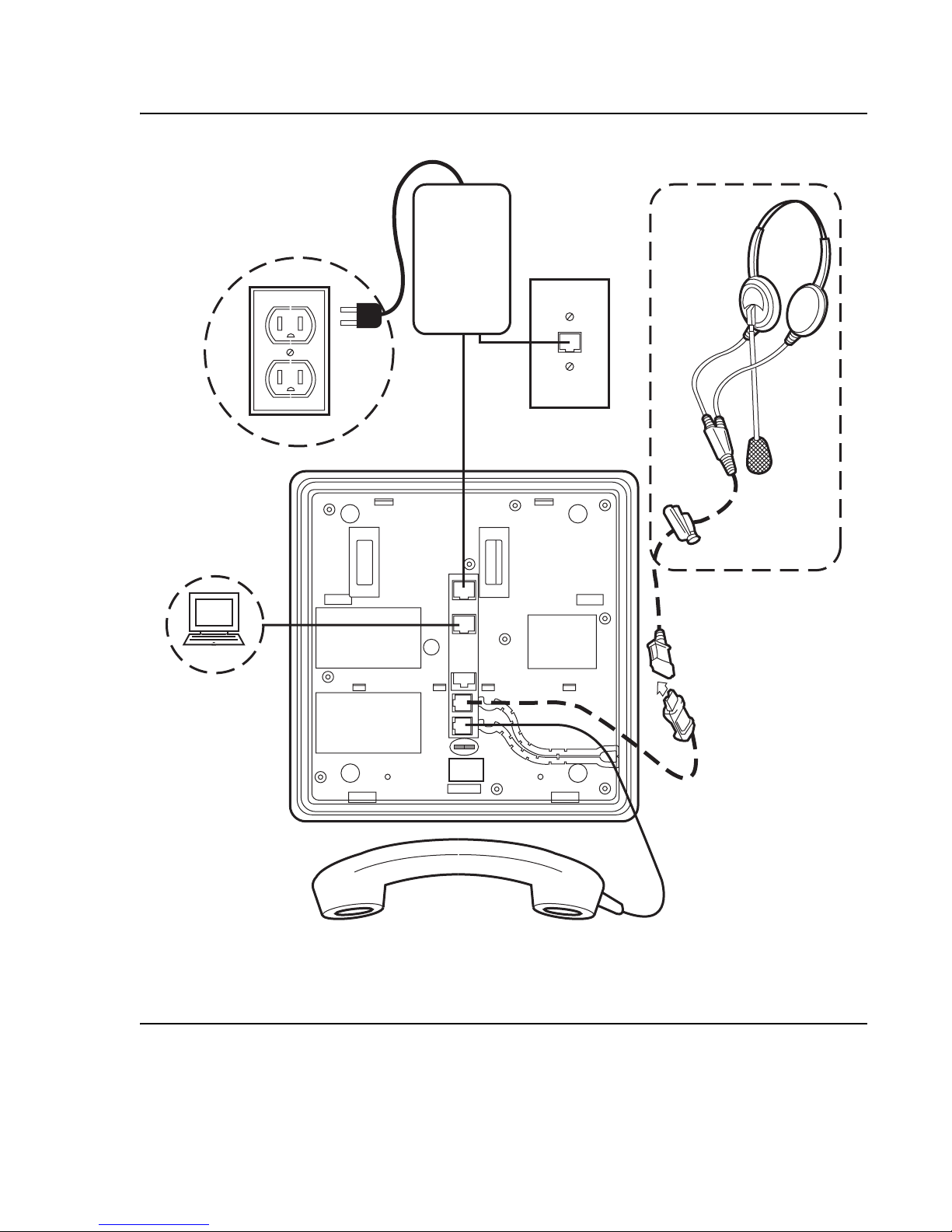
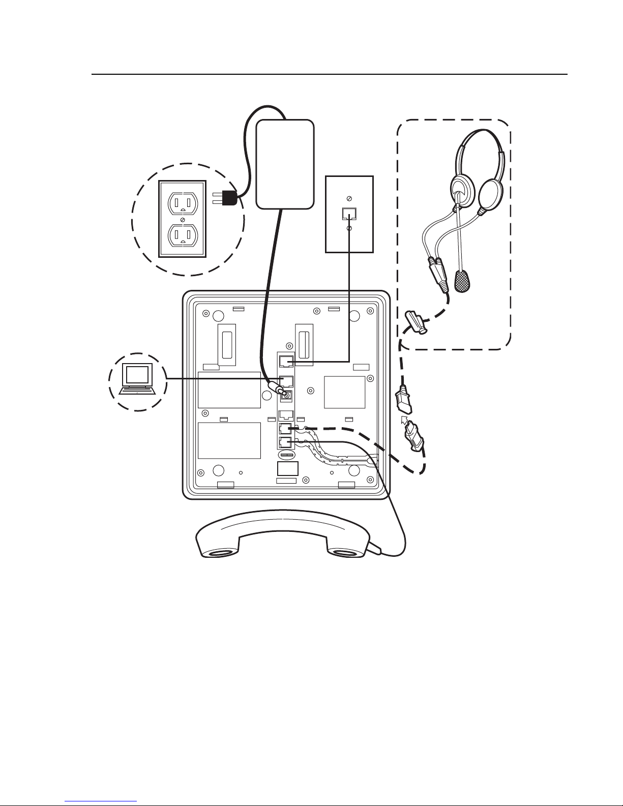
Figures 1 and 2 provide illustrations to connect cords to jacks on 9600 IP Series Telephones.
Use the illustrations and associated procedures as appropriate for telephone assembly.
Telephone Model: See:
9620 Figure 1
9630, 9640 Figure 2
9630G, 9640G Figure 3
Issue 2 December 2007 17

9600 Series SIP IP Telephone Installation
Figure 1: Connection Jacks on a 9620 Series SIP IP Telephone
MOD
L H
IEEE
18 9600 Series SIP IP Telephones Re le as e 2. 0 In st al la tio n and M ain t ena nc e Gui d e
Assembling the 9600 Series SIP IP Telephone
Figure 2: Connection Jacks on a 9630 & 9640 Series SIP IP Telephone
MOD
L H
IEEE
Issue 2 December 2007 19
9600 Series SIP IP Telephone Installation
Figure 3: Connection Jacks on a 9630G & 9640G Series SIP IP Telephone
MOD
L H
IEEE
20 9600 Series SIP IP Telephones Re le as e 2. 0 In st al la tio n and M ain t ena nc e Gui d e

Dynamic Addressing Process/Telephone Startup
1. Plug one end of the H4DU 4-conductor coiled handset cord into the telephone and the other
end into the handset.
2. Plug one end of the first Category 5e modular line cord into the Ethernet jack of the PC and
the other end into the secondary Ethernet jack on the 9600 Series IP Telephone,
if appropriate.
3. If the telephone is to be IEEE-powered, plug one end of t he second Category 5e mo dular
line cord into the Ethernet jack on the 9600 Series SIP IP Telephone. Plug the other end of
this cord into the Ethernet wall jack. If the telephone is to be IEEE-powered, you are
finished. Do not proceed to Step 4.
4. If the telephone is to be powered locally, connect one end of the second Category 5e
modular line cord into the Ethernet jack on the 9600 Series SIP IP Telephone. Plug the
other end of this cord into the 1151D power brick jack labeled Phone. Plug another
Category 5e cable into the 1151D power brick jack labeled Line. Plug the other end of this
cable into the Ethernet wall jack. Finally , connect the 1151D to an AC power source. Y ou are
now finished.
Dynamic Addressing Process/Telephone Startup
!
Important:
Important: Before starting this process, read Converting Software on 9600 Series IP
Telephones on page 14 to underst and the requirement s for converting factory- set
H.323 telephones to SIP and make any changes necessary to suit your particular
environment. Also, ensure that both Avaya Communication Manager (CM) and
SIP Enablement Services (SES) are properly set up for your telephone
environment.
Note:
Note: Before starting this process you must have an OPTIM extension number for the
SIP IP telephone, the Avaya Communication Manager security code (p assword),
and a login and password on the SES server.
Any reference to the HTTP server applies equally to an HTTPS server.
The following description of the process of installing the SIP IP telephones assumes that the
process is executed successfully. For errors that might be encountered during the process and
the messages displayed, see Chapter 5:
Troubleshooting Guidelines.
Issue 2 December 2007 21

9600 Series SIP IP Telephone Installation
When you plug the IP telephone set into the Ethernet wall jack and apply power, if applicable,
the following process takes place.
Note:
Note: If the application has already been downloaded, the whole process takes
approximately 1 to 2 minutes after the telephone is plugged in. For software
upgrades, including the boot file and application file download, the process might
take 5 - 10 minutes. The duration is based on LAN loading, how many telephones
are being installed at once, and similar factors.
Do not unplug the power cord during the download process.
1. The telephone activates the Ethernet line interface, the PC Ethernet jack, and dial p ad input
to allow the invocation of procedures. The activation occurs as soon as possible after
power-up or a reset.
2. During hardware initialization, configuration parameters are set to default values. The
system initialization values for contrast and brightness are checked for non-null values, and
set accordingly. The Avaya one-X™ name and logo display.
3. The system initialization value for the lang uage file in use is checked for a non-null valu e, in
which case the text strings in the language file named by that value are used for text
display. Otherwise, English text strings are displayed.
4. The boot code checks for a primary software code image, loads it into volat ile memory, and
transfers control to it. If a primary software code image is not found, the boot code loads
and transfers control to the backup software code image. Feedback displays in the form of a
moving outline on the black squares below the logo. The outline moves from one square to
the next to indicate processing is occurring.
When storage of a new backup image begins, Updating: displays on the Title Line and DO
NOT UNPLUG THE PHONE! displays on the Prompt Line until replaced by a subsequent
message. In addition, a progress bar consisting of an unfilled black rectangle displays,
centered on an Application Line below the logo image, as shown below.
The rectangle fills from left-to-right as storage proceeds, with the filled percentage of the
rectangle being approximately the same as the percentage of the file that has been stored.
!
Important:
Important: Pressing the Program softkey at any time during startup invokes the Craft
Access entry procedure to allow manual settings, but only if the PROCSTAT
(local dialpad procedure status) system value is “0” providing full access to local
procedures or if PROCSTAT is “1” in certain instances requiring input. For
information, see Chapter 3:
Local Administrative Options. If Craft procedures are
invoked, the startup process terminates. The Program softkey also displays in
conjunction with a message describing a processing conflict, for example, when
an ARP response indicates a conflict in obtaining the IP Address.
22 9600 Series SIP IP Telephones Re le as e 2. 0 In st al la tio n and M ain t ena nc e Gui d e

Dynamic Addressing Process/Telephone Startup
5. The telephone displays the speed of the Ethernet interface in Mbps, that is,
10, 100, or 1000. The message No Ethernet displays until the sof tware determin es whether
the interface is 10 Mbps, 100 Mbps, or 1000Mbps.
Note:
Note: The Ethernet speed indicated is the LAN interface speed for both the telephone
and any attached PC, assuming the administrator has not disabled the latter
interface by a PHY2STAT setting.
6. The IP telephone sends a request to the DHCP server and invokes the DHCP process.
The following message displays:
DHCP: s secs
where s is the number of seconds that have elapsed since DHCP was invoked.
7. VLAN verification and tagging occur. The following message displays:
VLAN ID = n
where n is the VLAN ID being used.
8. The DHCP server provides IP Addresses for the following hardware:
● The IP telephone
● The HTTP/HTTPS server
● The SIP Proxy server
9. Using the list of IP Addresses provided by the DHCP server, the telephone performs a
router check and verifies that the router is on the same subnet as the IP Address. The
telephone cycles through the gateway IP Addresses with ARPs or pings until it receives a
response.Using the list of gateway IP Addresses provided by the DHCP server, the
telephone. When the router is located, received LLDP TL Vs are processed. Then the HTTP
process starts.
Note:
Note: Any change in VLAN-related configuration parameters resulting from LLDP
triggers a telephone reset.
10. The HTTP process starts with an HTTP GET command, which displays on the telephone’s
Title Line.
Note:
Note: Pressing the Program softkey at any time during startup invokes the Craf t Access
entry procedure to allow manual settings, but only if the PROCSTAT (local
dialpad procedure status) system value is “0” providing full access to local
procedures or if PROCSTAT is “1” in certain instances requiring input. For
information, see Chapter 3:
Local Administrative Options. If Craft procedures are
invoked, the startup process terminates. The Program softkey also displays in
conjunction with a message describing a processing conflict, for example, when
an ARP response indicates a conflict in obtaining the IP Address.
Issue 2 December 2007 23
 Loading...