

Page 1

15-601042 Issue 30j - (18 May 2015)
Deploying Avaya IP Office™ Platform
IP500 V2
IP Office™ Platform 9.1
Page 2

Deploying Avaya IP Office™ Platform IP500 V2 Page 2
15-601042 Issue 30j (18 May 2015)IP Office™ Platform 9.1
Comments on this document? [email protected]
© 2015 AVAYA All Rights Reserved.
Notice
While reasonable efforts have been made to ensure that the information in this document is complete and accurate at the time of printing,
Avaya assumes no liability for any errors. Avaya reserves the right to make changes and corrections to the information in this document
without the obligation to notify any person or organization of such changes.
Documentation disclaimer
“Documentation” means information published by Avaya in varying mediums which may include product information, operating instructions and
performance specifications that Avaya may generally make available to users of its products and Hosted Services. Documentation does not
include marketing materials. Avaya shall not be responsible for any modifications, additions, or deletions to the original published version of
documentation unless such modifications, additions, or deletions were performed by Avaya. End User agrees to indemnify and hold harmless
Avaya, Avaya's agents, servants and employees against all claims, lawsuits, demands and judgments arising out of, or in connection with,
subsequent modifications, additions or deletions to this documentation, to the extent made by End User.
Link disclaimer
Avaya is not responsible for the contents or reliability of any linked websites referenced within this site or documentation provided by Avaya.
Avaya is not responsible for the accuracy of any information, statement or content provided on these sites and does not necessarily endorse
the products, services, or information described or offered within them. Avaya does not guarantee that these links will work all the time and has
no control over the availability of the linked pages.
Warranty
Avaya provides a limited warranty on Avaya hardware and software. Refer to your sales agreement to establish the terms of the limited
warranty. In addition, Avaya’s standard warranty language, as well as information regarding support for this product while under warranty is
available to Avaya customers and other parties through the Avaya Support website: http://www.avaya.com/support or such successor site as
designated by Avaya. Please note that if you acquired the product(s) from an authorized Avaya Channel Partner outside of the United States
and Canada, the warranty is provided to you by said Avaya Channel Partner and not by Avaya.
Licenses
THE SOFTWARE LICENSE TERMS AVAILABLE ON THE AVAYA WEBSITE, HTTP://SUPPORT.AVAYA.COM/LICENSEINFO, OR SUCH
SUCCESSOR SITE AS DESIGNATED BY AVAYA, ARE APPLICABLE TO ANYONE WHO DOWNLOADS, USES AND/OR INSTALLS
AVAYA SOFTWARE, PURCHASED FROM AVAYA INC., ANY AVAYA AFFILIATE, OR AN AVAYA CHANNEL PARTNER (AS
APPLICABLE) UNDER A COMMERCIAL AGREEMENT WITH AVAYA OR AN AVAYA CHANNEL PARTNER. UNLESS OTHERWISE
AGREED TO BY AVAYA IN WRITING, AVAYA DOES NOT EXTEND THIS LICENSE IF THE SOFTWARE WAS OBTAINED FROM ANYONE
OTHER THAN AVAYA, AN AVAYA AFFILIATE OR AN AVAYA CHANNEL PARTNER; AVAYA RESERVES THE RIGHT TO TAKE LEGAL
ACTION AGAINST YOU AND ANYONE ELSE USING OR SELLING THE SOFTWARE WITHOUT A LICENSE. BY INSTALLING,
DOWNLOADING OR USING THE SOFTWARE, OR AUTHORIZING OTHERS TO DO SO, YOU, ON BEHALF OF YOURSELF AND THE
ENTITY FOR WHOM YOU ARE INSTALLING, DOWNLOADING OR USING THE SOFTWARE (HEREINAFTER REFERRED TO
INTERCHANGEABLY AS “YOU” AND “END USER”), AGREE TO THESE TERMS AND CONDITIONS AND CREATE A BINDING
CONTRACT BETWEEN YOU AND AVAYA INC. OR THE APPLICABLE AVAYA AFFILIATE (“AVAYA”).
Avaya grants you a license within the scope of the license types described below, with the exception of Heritage Nortel Software, for which the
scope of the license is detailed below. Where the order documentation does not expressly identify a license type, the applicable license will be
a Designated System License. The applicable number of licenses and units of capacity for which the license is granted will be one (1), unless a
different number of licenses or units of capacity is specified in the documentation or other materials available to you. Software” means
Avaya’s computer programs in object code, provided by Avaya or an Avaya Channel Partner, whether as stand-alone products, pre-installed ,
or remotely accessed on hardware products, and any upgrades, updates, bug fixes, or modified versions thereto. “Designated Processor”
means a single stand-alone computing device. “Server” means a Designated Processor that hosts a software application to be accessed by
multiple users. “Instance” means a single copy of the Software executing at a particular time: (i) on one physical machine; or (ii) on one
deployed software virtual machine (“VM”) or similar deployment.
Designated System(s) License (DS). End User may install and use each copy or an Instance of the Software only on a number of Designated
Processors up to the number indicated in the order. Avaya may require the Designated Processor(s) to be identified in the order by type, serial
number, feature key, Instance, location or other specific designation, or to be provided by End User to Avaya through electronic means
established by Avaya specifically for this purpose.
Concurrent User License (CU). End User may install and use the Software on multiple Designated Processors or one or more Servers, so long
as only the licensed number of Units are accessing and using the Software at any given time. A “Unit” means the unit on which Avaya, at its
sole discretion, bases the pricing of its licenses and can be, without limitation, an agent, port or user, an e-mail or voice mail account in the
name of a person or corporate function (e.g., webmaster or helpdesk), or a directory entry in the administrative database utilized by the
Software that permits one user to interface with the Software. Units may be linked to a specific, identified Server or an Instance of the
Software.
Database License (DL). End User may install and use each copy or an Instance of the Software on one Server or on multiple Servers provided
that each of the Servers on which the Software is installed communicates with no more than an Instance of the same database.
CPU License (CP). End User may install and use each copy or Instance of the Software on a number of Servers up to the number indicated in
the order provided that the performance capacity of the Server(s) does not exceed the performance capacity specified for the Software. End
User may not re-install or operate the Software on Server(s) with a larger performance capacity without Avaya’s prior consent and payment of
an upgrade fee.
Page 3

Deploying Avaya IP Office™ Platform IP500 V2 Page 3
15-601042 Issue 30j (18 May 2015)IP Office™ Platform 9.1
Comments on this document? [email protected]
Named User License (NU). You may: (i) install and use the Software on a single Designated Processor or Server per authorized Named User
(defined below); or (ii) install and use the Software on a Server so long as only authorized Named Users access and use the Software. “Named
User,” means a user or device that has been expressly authorized by Avaya to access and use the Software. At Avaya’s sole discretion, a
“Named User” may be, without limitation, designated by name, corporate function (e.g., webmaster or helpdesk), an e-mail or voice mail
account in the name of a person or corporate function, or a directory entry in the administrative database utilized by the Software that permits
one user to interface with the Software.
Shrinkwrap License (SR). You may install and use the Software in accordance with the terms and conditions of the applicable license
agreements, such as “shrinkwrap” or “clickthrough” license accompanying or applicable to the Software (“Shrinkwrap License”).
Heritage Nortel Software
“Heritage Nortel Software” means the software that was acquired by Avaya as part of its purchase of the Nortel Enterprise Solutions Business
in December 2009. The Heritage Nortel Software currently available for license from Avaya is the software contained within the list of Heritage
Nortel Products located at http://support.avaya.com/LicenseInfo/ under the link “Heritage Nortel Products,” or such successor site as
designated by Avaya. For Heritage Nortel Software, Avaya grants Customer a license to use Heritage Nortel Software provided hereunder
solely to the extent of the authorized activation or authorized usage level, solely for the purpose specified in the Documentation, and solely as
embedded in, for execution on, or (in the event the applicable Documentation permits installation on non-Avaya equipment) for communication
with Avaya equipment. Charges for Heritage Nortel Software may be based on extent of activation or use authorized as specified in an order or
invoice.
Copyright
Except where expressly stated otherwise, no use should be made of materials on this site, the Documentation, Software, Hosted Service, or
hardware provided by Avaya. All content on this site, the documentation, Hosted Service, and the Product provided by Avaya including the
selection, arrangement and design of the content is owned either by Avaya or its licensors and is protected by copyright and other intellectual
property laws including the sui generis rights relating to the protection of databases. You may not modify, copy, reproduce, republish, upload,
post, transmit or distribute in any way any content, in whole or in part, including any code and software unless expressly authorized by Avaya.
Unauthorized reproduction, transmission, dissemination, storage, and or use without the express written consent of Avaya can be a criminal,
as well as a civil offense under the applicable law.
Virtualization
Each product has its own ordering code and license types. Note that each Instance of a product must be separately licensed and ordered. For
example, if the end user customer or Avaya Channel Partner would like to install two Instances of the same type of products, then two
products of that type must be ordered.
Third Party Components
“Third Party Components” mean certain software programs or portions thereof included in the Software or Hosted Service may contain
software (including open source software) distributed under third party agreements (“Third Party Components”), which contain terms regarding
the rights to use certain portions of the Software (“Third Party Terms”). As required, information regarding distributed Linux OS source code
(for those Products that have distributed Linux OS source code) and identifying the copyright holders of the Third Party Components and the
Third Party Terms that apply is available in the Documentation or on Avaya’s website at: http://support.avaya.com/Copyright or such successor
site as designated by Avaya. You agree to the Third Party Terms for any such Third Party Components.
Preventing Toll Fraud
“Toll Fraud” is the unauthorized use of your telecommunications system by an unauthorized party (for example, a person who is not a
corporate employee, agent, subcontractor, or is not working on your company's behalf). Be aware that there can be a risk of Toll Fraud
associated with your system and that, if Toll Fraud occurs, it can result in substantial additional charges for your telecommunications services.
Avaya Toll Fraud intervention
If you suspect that you are being victimized by Toll Fraud and you need technical assistance or support, call Technical Service Center Toll
Fraud Intervention Hotline at +1-800-643-2353 for the United States and Canada. For additional support telephone numbers, see the Avaya
Support website: http://support.avaya.com, or such successor site as designated by Avaya. Suspected security vulnerabilities with Avaya
products should be reported to Avaya by sending mail to: [email protected].
Trademarks
The trademarks, logos and service marks (“Marks”) displayed in this site, the Documentation, Hosted Service(s), and Product(s) provided by
Avaya are the registered or unregistered Marks of Avaya, its affiliates, or other third parties. Users are not permitted to use such Marks without
prior written consent from Avaya or such third party which may own the Mark. Nothing contained in this site, the Documentation, Hosted
Service(s) and Product(s) should be construed as granting, by implication, estoppel, or otherwise, any license or right in and to the Marks
without the express written permission of Avaya or the applicable third party.
Avaya is a registered trademark of Avaya Inc.
All non-Avaya trademarks are the property of their respective owners.
Linux® is the registered trademark of Linus Torvalds in the U.S. and other countries.
Page 4

Deploying Avaya IP Office™ Platform IP500 V2 Page 4
15-601042 Issue 30j (18 May 2015)IP Office™ Platform 9.1
Comments on this document? [email protected]
Downloading Documentation
For the most current versions of Documentation, see the Avaya Support website: http://support.avaya.com, or such successor site as
designated by Avaya.
Contact Avaya Support
See the Avaya Support website: http://support.avaya.com for Product or Hosted Service notices and articles, or to report a problem with your
Avaya Product or Hosted Service. For a list of support telephone numbers and contact addresses, go to the Avaya Support website:
http://support.avaya.com (or such successor site as designated by Avaya), scroll to the bottom of the page, and select Contact Avaya Support.
Page 5

Deploying Avaya IP Office™ Platform IP500 V2 Page 5
15-601042 Issue 30j (18 May 2015)IP Office™ Platform 9.1
Comments on this document? [email protected]
Contents
Contents
System Overview1.
..................................................................... 121.1 Additional Documentation
..................................................................... 121.2 Repair
..................................................................... 121.3 RoHS
..................................................................... 131.4 IP Office Modes
............................................................................ 141.4.1 System SD Cards
............................................................................ 151.4.2 Overall Capacity
............................................................................ 161.4.3 Hardware Support Summary
............................................................................ 171.4.4 Feature Support Summary
..................................................................... 181.5 The Control Unit
..................................................................... 191.6 IP500 V2 System Components
..................................................................... 211.7 Control Unit Cards
............................................................................ 211.7.1 IP500 Base Cards
............................................................................ 241.7.2 IP500 Trunk Cards
..................................................................... 251.8 External Expansion Modules
............................................................................ 261.8.1 IP500 External Expansion Modules
............................................................................ 281.8.2 IP400 External Expansion Modules
............................................................................ 291.8.3 Connecting External Expansion Modules
..................................................................... 301.9 Power Supplies and Cables
............................................................................ 301.9.1 Power Supplies
............................................................................ 311.9.2 Power Supply Cords
............................................................................ 321.9.3 Power Supply Backup
............................................................................ 331.9.4 Cabling and Cables
............................................................................ 351.9.5 Grounding
............................................................................ 36
1.9.6 Lightning Protection/Out-of-Building
Connections
..................................................................... 371.10 Wall and Rack Mounting
..................................................................... 381.11 Feature Keys and Licenses
..................................................................... 391.12 IP Office Phones
..................................................................... 411.13 VoIP
............................................................................ 421.13.1 Voice Compression Channels
..................................................................... 431.14 Supported Country Locales
..................................................................... 441.15 IP Office Software Applications
............................................................................ 451.15.1 Programming Applications
............................................................................ 461.15.2 User Applications
............................................................................ 461.15.3 Voicemail Applications
............................................................................ 471.15.4 Call Logging Applications
............................................................................ 471.15.5 Call Center Applications
............................................................................ 471.15.6 CTI Applications
..................................................................... 481.16 Training
..................................................................... 481.17 Web Sites
..................................................................... 491.18 Emergency and Power Failure Ports
Installation Requirements2.
..................................................................... 522.1 Environmental Requirements
..................................................................... 532.2 Space Requirements
............................................................................ 542.2.1 IP500 V2 Control Units
............................................................................ 542.2.2 External Expansion Modules
............................................................................ 552.2.3 Wall Mounting
............................................................................ 562.2.4 Rack Space Requirements
IP500 V2 Installation Overview3.
..................................................................... 593.1 Tools and Equipment Required
..................................................................... 603.2 Documentation
..................................................................... 613.3 Unpacking
Installing the Admin Software4.
..................................................................... 644.1 IP Office Web Manager
..................................................................... 654.2 Installing the Admin Applications
..................................................................... 674.3 Installer PC Connection
..................................................................... 684.4 Starting IP Office Manager
..................................................................... 694.5 Starting System Status Application
..................................................................... 704.6 Starting System Monitor
Preparing the System SD Card5.
..................................................................... 735.1 Upgrade the Card Firmware
..................................................................... 745.2 Creating an Offline Configuration File
..................................................................... 755.3 Adding a Pre-Built Configuration File
..................................................................... 755.4 Adding a License File
..................................................................... 755.5 Adding Security Certificates
..................................................................... 765.6 Adding a 9600 Series Screen Saver File
..................................................................... 765.7 Adding Music on Hold Files
Installing the Control Unit Cards6.
..................................................................... 796.1 Fitting IP500 Daughter Cards
..................................................................... 806.2 Inserting IP500 Base Cards
Installing the Physical System7.
..................................................................... 827.1 Wall Mounting
............................................................................ 837.1.1 Wall Mounting Kit V2/V3
..................................................................... 847.2 Rack Mounting
..................................................................... 857.3 Connecting External Expansion Modules
..................................................................... 877.4 Grounding
..................................................................... 887.5 Network Connection
..................................................................... 897.6 Starting the System
..................................................................... 907.7 Checking the LEDs
..................................................................... 927.8 Connecting Phones
............................................................................ 927.8.1 Analog Phones
............................................................................ 927.8.2 ETR Phones
............................................................................ 927.8.3 DS Digital Station Phones
............................................................................ 927.8.4 TCM/BST Phones
............................................................................ 937.8.5 IP/SIP Phones
Initial Configuration Using IP Office
Manager
8.
..................................................................... 978.1 Initial Configuration
..................................................................... 998.2 Entering Licenses
..................................................................... 1008.3 Setting the System Locale
..................................................................... 1018.4 Changing the IP Address Settings
..................................................................... 1028.5 Extension Numbering
..................................................................... 1048.6 Disable Unused Trunks
..................................................................... 1068.7 Setting the Digital Trunk Clock Source
..................................................................... 1088.8 Setting the Trunk Prefixes
..................................................................... 1108.9 DS16B/30B Port Mode Selection
Securing the System9.
..................................................................... 1139.1 Changing the Default Security Settings
..................................................................... 1149.2 Changing the Remote User Password
..................................................................... 1149.3 Disabling SIP Trunk Support
..................................................................... 1149.4 Disabling H.323 Telephone Support
On-Boarding10.
..................................................................... 11710.1 On-Boarding
SD Card Management11.
Page 6

Deploying Avaya IP Office™ Platform IP500 V2 Page 6
15-601042 Issue 30j (18 May 2015)IP Office™ Platform 9.1
Comments on this document? [email protected]
..................................................................... 12211.1 Booting from the SD Cards
..................................................................... 12411.2 Creating an IP Office SD Card
..................................................................... 12611.3 Viewing the Card Contents
..................................................................... 12711.4 Backing Up to the Backup Folder
............................................................................ 127
11.4.1 Backup to the Backup Folder Using IP
Office Manager
............................................................................ 127
11.4.2 Backup to the Backup Folder Using System
Status Application
............................................................................ 127
11.4.3 Backup to the Backup Folder Using a
System Phone
............................................................................ 128
11.4.4 Backup to the Backup Folder Using a IP
Office Web Manager
..................................................................... 12811.5 Restoring from the Backup Folder
............................................................................ 128
11.5.1 Restoring from the Backup Folder Using IP
Office Manager
............................................................................ 128
11.5.2 Restoring from the Backup Folder Using
System Status Application
............................................................................ 128
11.5.3 Restoring from the Backup Folder Using a
System Phone
............................................................................ 129
11.5.4 Restoring from the Backup Folder Using IP
Office Web Manager
..................................................................... 13111.6 Backing Up to the Optional SD Card
............................................................................ 131
11.6.1 Backing Up to the Optional SD Using IP
Office Manager
............................................................................ 131
11.6.2 Backing Up to the Optional SD Using
System Status Application
............................................................................ 132
11.6.3 Backing Up to the Optional SD Using IP
Office Web Manager
............................................................................ 132
11.6.4 Backing Up to the Optional SD Using a
System Phone
..................................................................... 13311.7 Restoring a Configuration from an Optional Card
............................................................................ 133
11.7.1 Restoring from the Optional SD Using IP
Office Manager
............................................................................ 133
11.7.2 Restoring from the Optional SD Using a
System Phone
..................................................................... 13411.8 Loading Software from an Optional SD Card
............................................................................ 134
11.8.1 Loading Software from the Optional SD
Using IP Office Manager
............................................................................ 134
11.8.2 Loading Software from the Optional SD
Using a System Phone
..................................................................... 13511.9 Backing Up to a PC
..................................................................... 13511.10 Restoring from a PC
..................................................................... 13711.11 Upgrading Card Software
..................................................................... 13811.12 Memory Card Shutdown/Removal
............................................................................ 13811.12.1 Shutdown a Card Using IP Office Manager
............................................................................ 138
11.12.2 Shutdown a Card Using System Status
Application
............................................................................ 139
11.12.3 Shutdown a Card Using IP Office Web
Manager
............................................................................ 13911.12.4 Shutdown a Card Using a System Phone
..................................................................... 14011.13 Memory Card Startup
............................................................................ 14011.13.1 Startup a Card Using IP Office Manager
............................................................................ 140
11.13.2 Startup a Card Using System Status
Application
............................................................................ 140
11.13.3 Startup a Card Using IP Office Web
Manager
............................................................................ 14011.13.4 Startup a Card Using a System Phone
Additional Processes12.
..................................................................... 143
12.1 Changing an IP Office Basic Edition System to
Standard Mode
..................................................................... 14412.2 Automating the Change to Standard Mode
..................................................................... 14512.3 Switching Off a System
............................................................................ 145
12.3.1 Shutdown a System Using IP Office
Manager
............................................................................ 146
12.3.2 Shutdown a System Using System Status
Application
............................................................................ 14612.3.3 Shutdown a System Using a System Phone
............................................................................ 14612.3.4 Shutdown a System Using the AUX Button
............................................................................ 146
12.3.5 Shutdown a System Using IP Office Web
Manager
..................................................................... 14712.4 Rebooting a System
............................................................................ 14712.4.1 Reboot a System Using IP Office Manager
............................................................................ 148
12.4.2 Reboot a System Using IP Office Web
Manager
............................................................................ 14812.4.3 Reboot a System Using the Reset Button
............................................................................ 14812.4.4 Rebooting a System Using a System Phone
..................................................................... 14912.5 Changing Components
............................................................................ 15012.5.1 Like for Like Replacement
............................................................................ 15012.5.2 Higher Capacity Replacement
............................................................................ 15012.5.3 Lower Capacity Replacement
............................................................................ 15012.5.4 Adding a New Component
............................................................................ 15112.5.5 Permanent Removal
............................................................................ 15112.5.6 Replacemnt with a Different Type
..................................................................... 15212.6 Defaulting the Configuration
............................................................................ 152
12.6.1 Defaulting the Configuration Using IP Office
Manager
............................................................................ 152
12.6.2 Defaulting the Configuration Using IP Office
Web Manager
............................................................................ 152
12.6.3 Defaulting the Configuration Using the
Reset Button
............................................................................ 153
12.6.4 Default the Configuration Using a System
Phone
............................................................................ 15312.6.5 Defaulting the Configuration Using Debug
............................................................................ 154
12.6.6 Defaulting the Configuration Using Boot
Loader
..................................................................... 15512.7 Defaulting Security Settings
............................................................................ 15612.7.1 Defaulting Security Using IP Office Manager
............................................................................ 156
12.7.2 Defaulting Security Using IP Office Web
Manager
............................................................................ 15712.7.3 Defaulting Security using the RS232 Port
............................................................................ 15812.7.4 Defaulting Security Using the Boot Loader
..................................................................... 15912.8 Loading a Configuration
............................................................................ 16012.8.1 Creating an Offline Configuration File
............................................................................ 161
12.8.2 Loading a Configuration Using IP Office
Manager
............................................................................ 161
12.8.3 Loading a Configuration Using IP Office
Web Manager
............................................................................ 161
12.8.4 Loading a Configuration onto a System SD
Card
..................................................................... 16212.9 Upgrading systems
............................................................................ 16312.9.1 Upgrade Using the Upgrade Wizard
............................................................................ 165
12.9.2 Remote Upgrade the System SD Card
Using Manager
............................................................................ 16512.9.3 Upgrading the SD Card Locally
............................................................................ 16612.9.4 Upgrading an SD Card in a PC
............................................................................ 16712.9.5 Upgrading Using IP Office Web Manager
..................................................................... 16912.10 Swapping Extension Users
..................................................................... 17012.11 Out of Building Telephone Installations
............................................................................ 17112.11.1 DS Phones
............................................................................ 17212.11.2 Analog Phone Barrier Box
............................................................................ 17312.11.3 Rack Mounting Barrier Boxes
..................................................................... 17412.12 Using the External Output Port
............................................................................ 17412.12.1 Port Connection
Page 7

Deploying Avaya IP Office™ Platform IP500 V2 Page 7
15-601042 Issue 30j (18 May 2015)IP Office™ Platform 9.1
Comments on this document? [email protected]
Contents
..................................................................... 17512.13 So8 BRI Module
............................................................................ 17512.13.1 Example 1: ISDN Terminal
............................................................................ 17612.13.2 Example 2: Video Conference
..................................................................... 17812.14 SNMP
............................................................................ 17912.14.1 Installing the IP Office MIB Files
............................................................................ 18112.14.2 Enabling SNMP and Polling Support
............................................................................ 18112.14.3 Enabling SNMP Trap Sending
..................................................................... 18212.15 Reset Button
..................................................................... 18212.16 AUX Button
..................................................................... 18312.17 RS232 Port Maintenance
..................................................................... 18412.18 Erasing the Core Software
............................................................................ 184
12.18.1 Erasing Core Software Using the Reset
Button
............................................................................ 18512.18.2 Erasing Core Software Using Debug
............................................................................ 186
12.18.3 Erasing Core Software Using the Boot
Loader
..................................................................... 18712.19 Enabling IP Office Web Manager
System Components13.
..................................................................... 19113.1 IP500 V2 Control Unit
..................................................................... 19413.2 IP500 Base Cards
............................................................................ 19713.2.1 4-Port Expansion Card
............................................................................ 19813.2.2 Analog Phone
............................................................................ 19913.2.3 ATM Combination Card
............................................................................ 20113.2.4 BRI Combination Card
............................................................................ 20213.2.5 Unified Communications Module
............................................................................ 20313.2.6 Digital Station
............................................................................ 20413.2.7 ETR6 Card
............................................................................ 20613.2.8 TCM8 Digital Station
............................................................................ 20713.2.9 VCM
..................................................................... 20913.3 IP500 Trunk Daughter Cards
............................................................................ 21013.3.1 Analog Trunk Card
............................................................................ 21213.3.2 BRI Trunk Cards
............................................................................ 21313.3.3 PRI Trunk Cards
..................................................................... 21413.4 IP500 External Expansion Modules
............................................................................ 21613.4.1 Analog Trunk 16
............................................................................ 21813.4.2 BRI So8
............................................................................ 22013.4.3 Digital Station 16/30
............................................................................ 22213.4.4 Digital Station 16A/30A
............................................................................ 22513.4.5 Digital Station 16B/30B
............................................................................ 22713.4.6 Phone 16/30
..................................................................... 22913.5 IP400 Expansion Modules
............................................................................ 23013.5.1 Analog Trunk 16
............................................................................ 23213.5.2 Digital Station V2
............................................................................ 23413.5.3 Phone V2
..................................................................... 23613.6 SD Cards
............................................................................ 23613.6.1 IP500 V2 System SD Cards
..................................................................... 23813.7 Mounting Kits
............................................................................ 23813.7.1 IP500 Wall Mounting Kits
............................................................................ 23813.7.2 Barrier Box Rack Mounting Kit
..................................................................... 23913.8 Phones
............................................................................ 24113.8.1 1010/1040
............................................................................ 24213.8.2 1120/1140/1220/1230
............................................................................ 24313.8.3 1403
............................................................................ 24413.8.4 1408
............................................................................ 24513.8.5 1416
............................................................................ 24613.8.6 1603
............................................................................ 24813.8.7 1608
............................................................................ 25013.8.8 1616
............................................................................ 25213.8.9 2402
............................................................................ 25313.8.10 2410
............................................................................ 25413.8.11 2420
............................................................................ 25513.8.12 3616
............................................................................ 25613.8.13 3620
............................................................................ 25713.8.14 3626
............................................................................ 25813.8.15 3641
............................................................................ 25913.8.16 3645
............................................................................ 26013.8.17 3701
............................................................................ 26113.8.18 3711
............................................................................ 26213.8.19 3720
............................................................................ 26313.8.20 3725
............................................................................ 26413.8.21 3740
............................................................................ 26513.8.22 3749
............................................................................ 26613.8.23 3810
............................................................................ 26713.8.24 3910
............................................................................ 26713.8.25 3920
............................................................................ 26813.8.26 4406
............................................................................ 26913.8.27 4412
............................................................................ 27013.8.28 4424
............................................................................ 27113.8.29 4601
............................................................................ 27213.8.30 4602
............................................................................ 27313.8.31 4610
............................................................................ 27413.8.32 4620
............................................................................ 27513.8.33 4621
............................................................................ 27613.8.34 4625
............................................................................ 27713.8.35 5402
............................................................................ 27813.8.36 5410
............................................................................ 27913.8.37 5420
............................................................................ 28013.8.38 5601
............................................................................ 28113.8.39 5602
............................................................................ 28213.8.40 5610
............................................................................ 28313.8.41 5620
............................................................................ 28413.8.42 5621
............................................................................ 28513.8.43 9504
............................................................................ 28613.8.44 9508
............................................................................ 28713.8.45 9608, 9608G
............................................................................ 28813.8.46 9611G
............................................................................ 29013.8.47 9620L, 9620C
............................................................................ 29213.8.48 9621G
............................................................................ 29313.8.49 9630G
............................................................................ 29513.8.50 9640, 9640G
............................................................................ 29713.8.51 9641G
............................................................................ 29813.8.52 9650, 9650C
............................................................................ 30013.8.53 Audio Conferencing Unit
............................................................................ 30113.8.54 B100 Series
............................................................................ 30213.8.55 D100 Series
............................................................................ 30313.8.56 E129
............................................................................ 30413.8.57 ETR 6, ETR 6D
............................................................................ 30513.8.58 ETR 18, ETR 18D
............................................................................ 30613.8.59 ETR 34D
............................................................................ 30713.8.60 M7100
............................................................................ 30713.8.61 M7100N
............................................................................ 30813.8.62 M7208
............................................................................ 30813.8.63 M7208N
............................................................................ 30913.8.64 M7310
............................................................................ 30913.8.65 M7310N
............................................................................ 31013.8.66 M7324
Page 8

Deploying Avaya IP Office™ Platform IP500 V2 Page 8
15-601042 Issue 30j (18 May 2015)IP Office™ Platform 9.1
Comments on this document? [email protected]
............................................................................ 31013.8.67 M7324N
............................................................................ 31113.8.68 T7000
............................................................................ 31113.8.69 T7100
............................................................................ 31213.8.70 T7208
............................................................................ 31313.8.71 T7316
............................................................................ 31413.8.72 T7316E
............................................................................ 31513.8.73 T7406, T7406e
............................................................................ 31613.8.74 T3 Classic
............................................................................ 31713.8.75 T3 Comfort
............................................................................ 31813.8.76 T3 Compact
..................................................................... 31913.9 Phone Add-Ons
............................................................................ 32013.9.1 201B RIM
............................................................................ 32113.9.2 4450
............................................................................ 32213.9.3 BM32
............................................................................ 32313.9.4 DBM32
............................................................................ 32413.9.5 EU24
............................................................................ 32513.9.6 EU24BL
............................................................................ 32613.9.7 KLM Module
............................................................................ 32713.9.8 SMB24
............................................................................ 32813.9.9 T3 DSS
............................................................................ 32913.9.10 T7316e KEM
............................................................................ 33013.9.11 XM24
..................................................................... 33113.10 Ancilliary Systems
............................................................................ 33113.10.1 Digitial Mobility Solution
............................................................................ 33213.10.2 DECT R4
..................................................................... 33313.11 Applications
............................................................................ 33413.11.1 IP Office Application Server
............................................................................ 33413.11.2 ContactStore
............................................................................ 33513.11.3 IP Office Manager
............................................................................ 33513.11.4 Monitor
............................................................................ 33513.11.5 one-X Portal for IP Office
............................................................................ 33613.11.6 Avaya Communicator
............................................................................ 33713.11.7 SoftConsole
............................................................................ 33713.11.8 IP Office Video SoftPhone
............................................................................ 33913.11.9 System Status Application
............................................................................ 34013.11.10 TAPI
............................................................................ 34113.11.11 Voicemail Pro
............................................................................ 34113.11.12 Web Collaboration
............................................................................ 34113.11.13 IP Office Ports
..................................................................... 34313.12 Operating System Summary
............................................................................ 34313.12.1 Windows Support
............................................................................ 34513.12.2 Mac OS Support
............................................................................ 34513.12.3 Linux Support
............................................................................ 34513.12.4 Browser Support
..................................................................... 34613.13 Physical Ports
............................................................................ 34713.13.1 Cables
............................................................................ 34913.13.2 ANALOG Port
............................................................................ 34913.13.3 AUDIO Port
............................................................................ 35013.13.4 BRI Port (So)
............................................................................ 35113.13.5 BRI Port (To)
............................................................................ 35213.13.6 BST Port (RJ21)
............................................................................ 35213.13.7 BST Port (RJ45)
............................................................................ 35313.13.8 DC I/P Port
............................................................................ 35313.13.9 DS Ports (RJ45)
............................................................................ 35413.13.10 EF Port
............................................................................ 35413.13.11 ETR Port
............................................................................ 35513.13.12 EXPANSION Port
............................................................................ 35513.13.13 EXT O/P Port
............................................................................ 35613.13.14 LAN Port
............................................................................ 35713.13.15 PF Port
............................................................................ 35813.13.16 PHONE (POT) Port
............................................................................ 35913.13.17 PRI Port
............................................................................ 36013.13.18 RS232 Port (DTE)
..................................................................... 36113.14 Licences
............................................................................ 36213.14.1 System Edition Licenses
............................................................................ 36313.14.2 Upgrade Licenses
............................................................................ 36413.14.3 Trunk Licensing
............................................................................ 36513.14.4 Telephone/Endpoint Licenses
............................................................................ 36613.14.5 User Licenses
............................................................................ 36913.14.6 Voicemail Pro Licenses
............................................................................ 37113.14.7 Trial Licenses
............................................................................ 37213.14.8 CTI Licenses
............................................................................ 37213.14.9 Other Licenses
..................................................................... 37313.15 Hardware/Software Compatibility
..................................................................... 38113.16 Hardware PCS Levels
..................................................................... 38113.17 TAA
Safety Statements14.
..................................................................... 38414.1 Lightning Protection/Hazard Symbols
..................................................................... 38514.2 Trunk Interface Modules
..................................................................... 38614.3 Further Information and Product Updates
..................................................................... 38614.4 Port Safety Classification
..................................................................... 38714.5 EMC Directive
..................................................................... 38814.6 Regulatory Instructions for Use
............................................................................ 38814.6.1 Australia
............................................................................ 38814.6.2 Canada
............................................................................ 38914.6.3 China
............................................................................ 39014.6.4 Japan
............................................................................ 39014.6.5 European Union
............................................................................ 39114.6.6 New Zealand
............................................................................ 39214.6.7 FCC Notification
............................................................................ 39414.6.8 Compliance with FCC Rules
Document History15.
...............................................................................397Index
Page 9

Deploying Avaya IP Office™ Platform IP500 V2 Page 9
15-601042 Issue 30j (18 May 2015)IP Office™ Platform 9.1
Comments on this document? [email protected]
System Overview
Chapter 1.
Page 10

Page 11

Deploying Avaya IP Office™ Platform IP500 V2 Page 11
15-601042 Issue 30j (18 May 2015)IP Office™ Platform 9.1
Comments on this document? [email protected]
System Overview:
1. System Overview
The Avaya IP Office IP 500 V2 is also known as "IPO IP500 V2 Cntrl Unit", "IP Office IP 500 v2", "IPO IP500 v2", "IP 500
V2", "IP500 V2", "IPO 500v2 System Unit Assembly" or "IP Office 500 v2". Throughout this documentation the term
IP500 V2 is used.
This document is intended to assist with the installation of an IP Office system running in IP Office standard mode (IP
Office Essential Edition or IP Office Preferred Edition) using an IP500 V2 control unit.
This documentation does not cover installation of IP Office Basic Edition, IP Office Basic Edition - Norstar Mode or IP
Office Basic Edition - PARTNER® Mode systems which each have their own separate installation documentation.
· The IP Office is a converged voice and data communications system. It should therefore only be installed by
persons with telephony and IP data network experience.
· Installers must be trained on IP Office systems. Through its Avaya University (AU), Avaya provides a range of
training courses including specific IP Office implementation and installation training. It also provides certification
schemes for installers to achieve various levels of IP Office accreditation.
· It is the installer’s responsibility to ensure that all installation work is done in accordance with local and national
regulations and requirements. It is also their responsibility to accurately establish the customer’s requirements
before installation and to ensure that the installation meets those requirements.
· You should read and understand this documentation before installation. You should also obtain and read the Avaya
Technical Bulletins relevant to recent software and hardware releases to ensure that you are familiar with any
changes to the IP Office equipment and software.
48
Page 12

Deploying Avaya IP Office™ Platform IP500 V2 Page 12
15-601042 Issue 30j (18 May 2015)IP Office™ Platform 9.1
Comments on this document? [email protected]
1.1 Additional Documentation
Additional Documentation
The following components of core system are outside the range of a basic system installation. They are covered by
separate installation and configuration documentation. If those components are to be part of the system installation, that
documentation should be obtained, read and understood prior to the installation.
· Avaya IP Office Platform Security Guidelines
· one-X Portal for IP Office Installation.
· Avaya H323 IP Phone Installation.
· Embedded Voicemail Installation.
· Voicemail Pro Installation.
· Contact Store Installation.
· Compact DECT Installation.
· IP DECT R4 Installation.
· 3600 Series Wireless IP Installation.
· SoftConsole Installation Manual.
· SIP Extension Configuration.
· 1100/1200 Series Phone Installation.
· ! IP Office Technical Bulletins
Ensure that you have obtained and read the IP Office Technical Bulletin relating to the IP Office software release
which you are installing. This bulletin will contain important information that may not have been included in this
manual. IP Office Technical Bulletins are available from the Avaya support website (http://support.avaya.com).
· ! Upgrade Licenses
Some upgrades may require entry of upgrade licenses. It is still possible to upgrade the system without the
necessary licenses, however the system will not provide any telephony functions after the upgrade until the
appropriate license is added to the system configuration.
1.2 Repair
IP Office systems do not contain any user serviceable or repairable components. If a faulty unit is suspected, the whole
unit should be replaced.
IP Office control units should not be opened under any circumstances except the insertion of IP500 base cards.
1.3 RoHS
RoHS is a European Union directive for the Removal of Certain Hazardous Substances from Electrical and Electronic
Equipment. Similar legislation has been or is being introduced in a number of other countries. Avaya has decided to make
its global product range compliant with the requirements of RoHS.
The actions taken vary
· In some cases equipment has been discontinued and is no longer available from Avaya.
· In some cases new manufactured stock has been made RoHS compliant and keeps its existing SAP code.
· In other cases the equipment has been replaced by a new RoHS compliant alternative with new SAP codes.
· The SAP codes within this document are for RoHS compliant equipment unless otherwise stated.
Page 13

Deploying Avaya IP Office™ Platform IP500 V2 Page 13
15-601042 Issue 30j (18 May 2015)IP Office™ Platform 9.1
Comments on this document? [email protected]
System Overview: RoHS
1.4 IP Office Modes
IP Office systems can run in a number of modes. The following modes are supported by IP500 V2 control units:
IP Office Standard Modes
The following operating modes are collectively referred to as IP Office standard mode.
· IP Office Essential Edition
This is the default mode for an IP500 control unit. For IP Office Release 9.1, IP500 V2 systems run in this mode if
an Essential Edition license is added to the configuration. Systems without a license will not support any
telephony functions.
· IP Office Preferred Edition
This mode is similar to IP Office Essential Edition but adds support for the Voicemail Pro application. This mode is
enabled by adding a Preferred Edition (Voicemail Pro) license to a system already licensed for Essential
Edition.
IP Office Basic Edition Modes
The following operating modes are collectively referred to as IP Office basic mode. These modes are supported by IP500
V2 control units only.
· IP Office Basic Edition
This is the default operating mode for IP500 V2 control units.
· IP Office Basic Edition - Norstar Mode
This mode operates the same as the IP Office Basic Edition mode. This mode is sold in Middle East and North
African locales.
· IP Office Basic Edition - PARTNER® Mode
This mode operates the same as the IP Office Basic Edition mode. This mode is sold in North American locales.
Other Modes
· Server Edition
This special mode is not covered by this documentation. Refer to the separate Server Edition documentation. An
IP500 V2 system can be used in a Server Edition network as an IP500 V2 Expansion System system. Therefore,
the hardware compatibility notes for the IP500 V2 control unit in this manual remain applicable for Server Edition
usage unless stated otherwise.
· IP Office™ Platform Select
This mode enabled additional capacity features on Server Edition systems.
Page 14

Deploying Avaya IP Office™ Platform IP500 V2 Page 14
15-601042 Issue 30j (18 May 2015)IP Office™ Platform 9.1
Comments on this document? [email protected]
1.4.1 System SD Cards
IP500 V2 control unit must be fitted with a System SD card. The default mode of the system is determined by the type of
System SD card present. By using IP Office Manager and adding licenses the mode of the system can be changed.
The different System SD cards are:
· IP Office U-Law SD Card
A system fitted with this type of card defaults to U-Law telephony. For pre-IP Office Release 7.0 software, the
system will default to IP Office standard mode. For IP Office Release 7.0+, the system will default to IP Office
Basic Edition Key System operation. Intended for North American locales.
· IP Office A-Law SD Card
A system fitted with this type of card defaults to A-Law telephony. For pre-IP Office Release 7.0 software, the
system will default to IP Office standard mode. For IP Office Release 7.0+, the system will default to IP Office
Basic Edition PBX System operation. Intended for locales outside North America.
· IP Office Partner Edition SD Card
A system fitted with this type of card defaults to U-Law telephony and IP Office Basic Edition - PARTNER®
Mode Key System operation. Supported only in North American locales.
· IP Office Norstar Edition SD Card
A system fitted with this type of card defaults to A-Law telephony and IP Office Basic Edition - Norstar Mode
Key System operation. Supported only in Middle East and North African locales.
Page 15
Deploying Avaya IP Office™ Platform IP500 V2 Page 15
15-601042 Issue 30j (18 May 2015)IP Office™ Platform 9.1
Comments on this document? [email protected]
System Overview: IP Office Modes
1.4.2 Overall Capacity
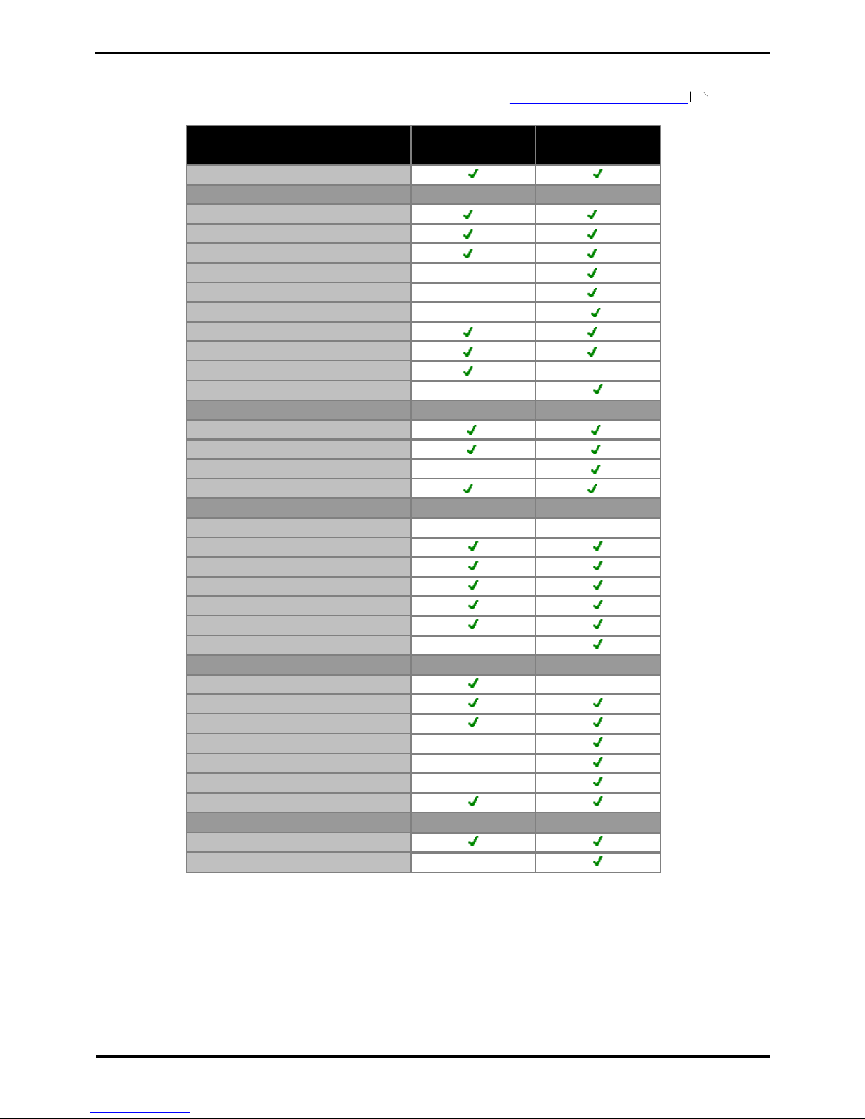
The following table is a summary only. The exact combinations of extension, trunk and user ports also depends on local
variations in hardware support. For example, BRI trunks are not supported in North American locales.
IP Office
Basic Edition
- PARTNER®
Mode
IP Office
Basic Edition
- Norstar
Mode
IP Office
Basic Edition
Standard
Mode
Extensions
Maximum Extensions
100
[1]
100
[1]
100
[1]
384
Trunks
Maximum Trunks
646464
[5]
- Maximum Analog Trunks
323232
204
- Maximum BRI Channels
[3]
–1212
32
- Maximum PRI Channels
[4]
243030
240
- Maximum SIP Channels
[2]
202020
[5]
- Maximum H323 IP Channels
–––
[5]
1.100 Extensions in 3-digit extension numbering mode. 48 extensions in 2-digit extension numbering mode.
· For IP Office Basic Edition modes, the system assumes that the base control unit is always fully populated with
up to 32 extensions, either real or phantom or a mix, to which it assigns extension numbers in sequence. It
does this before assigning extension numbers to any real extensions on attached external expansion modules
up to the system extension limit. If the system extension limit has not been exceeded, any remaining
extension numbers are assigned to additional phantom extensions.
2.IP Office Basic Edition mode systems support 3 SIP channels without licenses. Additional channels up to the limit
require licenses. IP Office standard mode systems require licenses for all channels. In all modes, voice
compression hardware resources are also required for SIP support.
3.IP Office Basic Edition mode systems do not support both BRI and PRI trunks in the same system. They are also
restricted to 12 BRI channels regardless of the BRI hardware installed. IP Office standard mode systems support
both BRI and PRI trunks in the same system.
4.IP Office Basic Edition mode systems are limited to 1 single-port PRI card.
5.Capacity is dependent on licenses, voice compression resources and available bandwidth.
Page 16
Deploying Avaya IP Office™ Platform IP500 V2 Page 16
15-601042 Issue 30j (18 May 2015)IP Office™ Platform 9.1
Comments on this document? [email protected]
1.4.3 Hardware Support Summary
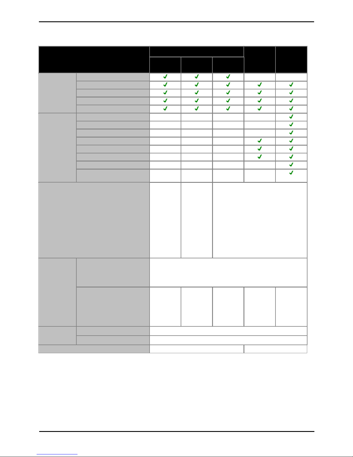
Note that even where indicated as supported, the availability and support of equipment may still be subject to local
restrictions. The table below is a summary for IP Office Release 9.1, refer to Hardware Software Compatibility for a
more historical summary and for a listing of supported telephones.
IP Office Basic
Edition modes
IP Office standard
modes
IP500 V2 Control Unit
IP500 Base Cards
IP500 Digital Station Card
3
3
IP500 Analog Phone 2/8
4
4
IP500 TCM8 Card
4
4
IP500 VCM 32/64 Cards
–
2
IP500 4-Port Expansion
–
1
IP500 BRI Combo
[2]
–
IP500 ATM Combo
[2]
2
2
IP500 ATM Combo V2
[2]
2
2
IP500 ETR6
[1][6]
3
–
Unified Communications Module
[6]
–
Trunk Daughter Cards
Analog Trunk Card
Analog Trunk Card V2
BRI Trunk Cards
[4]
–
PRI Trunk Card
[4][5]
1
4
Expansion Modules
Number of Modules
[3]
8
12
Digital Station 16/30
Digital Station 16A/30A
Digital Station 16B/30B
Phone 8/16/30
Analog Trunk 16
BRI So8
–
Telephone Types
ETR Phones (ETR ports)
–
BST Phones (BST ports)
DS Phones (DS ports)
H323 IP Phones (LAN)
–
SIP IP Phones (LAN)
–
DECT R4 (LAN)
–
DECT DMS (BST ports)
Voicemail Types
Embedded Voicemail
Voicemail Pro
–
1.The ETR6 card is only supported by IP500 V2 systems in IP Office Basic Edition - PARTNER® Mode or IP Office
Basic Edition U-Law modes.
2.Only 2 combinations cards are supported in a control unit, regardless of combination card type.
3.External expansion modules can be added so long as the overall limit for extensions and trunks is not exceeded.
On IP Office Basic Edition mode systems, a maximum of one Analog Trunk 16 module is supported.
4.IP Office Basic Edition mode systems do not support a mix of BRI and PRI trunks.
5.IP Office Basic Edition mode systems only support a single-port PRI card.
373
Page 17
Deploying Avaya IP Office™ Platform IP500 V2 Page 17
15-601042 Issue 30j (18 May 2015)IP Office™ Platform 9.1
Comments on this document? [email protected]
System Overview: IP Office Modes
1.4.4 Feature Support Summary
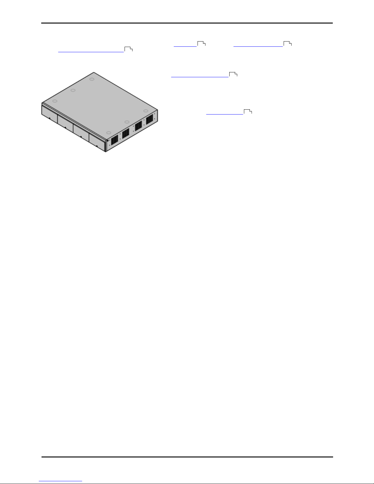
The table below is a general summary only. For more specific details refer to the installation documentation for the
specific application.
IP Office Basic Edition
IP Office
Essential
Edition
IP Office
Preferred
Edition
PARTNER
Mode
Norstar
Mode
Quick Mode
Admin
Applications
Phone Based Admin
–
–
IP Office Web Manager
IP Office Manager
Monitor (System Monitor)
System Status Application
Applications
one-X Portal for IP Office
–––
–
one-X Mobile
–––
–
Avaya Communicator
–––
–
SoftConsole
–––
TAPI (1st Party)
–––
TAPI (3rd Party)
–––
Voicemail Pro
–––
–
Contact Recorder for IP
Office
–––
–
Locales
Canada,
Mexico,
United
States.
Bahrain,
Egypt,
Kuwait,
Morocco,
Oman,
Pakistan,
Qatar, Saudi
Arabia,
South Africa,
Turkey,
United Arab
Emirates.
Argentina, Australia, Bahrain, Belgium,
Brazil, Canada, Chile, China, Colombia,
Czech, Denmark, Egypt, Finland, France,
Germany, Greece, Hong Kong, Hungary,
Iceland, India, Ireland, Italy, Japan,
Korea, Kuwait, Malaysia, Mexico,
Morocco, Netherlands, New Zealand,
Norway, Oman, Pakistan, Peru,
Philippines, Poland, Portugal, Qatar,
Russia, Saudi Arabia, Singapore, South
Africa, Spain, Sweden, Switzerland,
Taiwan, Turkey, United Arab Emirates,
United Kingdom, United States,
Venezuela.
Voicemail
Languages
Embedded Voicemail
· Arabic, Chinese-Mandarin, Chinese-Cantonese, Danish, Dutch,
English-UK, English-US, Finnish, French, French-Canadian,
German, Italian, Korean, Norwegian, Portuguese, Portuguese
Brazilian, Russian, Swedish, Spanish, Spanish-Latin, SpanishArgentinean.
Voicemail Pro
––––As above
plus:
Hungarian,
Greek,
Polish.
Minus:
Arabic.
Default
Configuration
Access
User Name
Administrator
Password
Administrator
Default Upgrade Password
Administrator
password
Page 18
Deploying Avaya IP Office™ Platform IP500 V2 Page 18
15-601042 Issue 30j (18 May 2015)IP Office™ Platform 9.1
Comments on this document? [email protected]
1.5 The Control Unit
The base of any IP Office system is the control unit. It stores the system configuration and controls the system operation.
Each control unit can be customized by inserting various base card onto which trunk daughter cards can also be
added. External expansion modules can also be connected to add additional extension and trunk ports.
IP Office Release 9.1 supports the following IP Office control units. Other previous types of IP Office control units are not
supported by IP Office Release 9.1 and are not covered by this documentation.
· IP500 V2 Control Unit
This control unit has four front slots for IP500 base cards. It has
an internal power supply unit and uses a mandatory System SD
card. It includes a 2 port ethernet LAN switch (layer 3 managed)
on the rear.
· The type of System SD card fitted to the system determines
its default operation mode of the system. The possible
modes are listed below. Some modes require the addition of
licenses:
· IP Office Basic Edition
· IP Office Basic Edition - PARTNER® Mode
· IP Office Basic Edition - Norstar Mode
· IP Office Essential Edition
· IP Office Preferred Edition
· Server Edition
21 24
25
191
13
Page 19

Deploying Avaya IP Office™ Platform IP500 V2 Page 19
15-601042 Issue 30j (18 May 2015)IP Office™ Platform 9.1
Comments on this document? [email protected]
System Overview: The Control Unit
1.6 IP500 V2 System Components
The following are the typical components of a system based on an IP500 V2 control unit.
· IP Office IP500 V2 System Unit
The control unit holds the main configuration and performs the
routing and switching for telephone calls and data traffic. Each
control unit includes 4 slots for optional base cards to support
trunk and phone extension ports.
· Avaya SD Card
This uniquely numbered dongle is used to validate license
keys entered into the system's configuration to enable
features. A dongle is mandatory for correct system operation
even if no licensed features are being used. IP500 V2 control
units use an Avaya SD card which is slotted into the rear of
the control unit. This card also provides Embedded Voicemail
support and storage for system software files.
· IP500 Base Cards
The IP500 V2 control unit has slots for up to 4 IP500 base cards.
These can be used to add ports for analog extensions, digital
extensions, voice compression channels and other resources.
· IP500 Digital Station Base Card
· IP500 Analog Phone Base Card
· IP500 VCM Base Card
· IP500 4-Port Expansion Base Card
· IP500 TCM8 Base Card
· IP500 ETR6 Base Card
· Unified Communications Module
· IP500 Trunk Daughter Cards
Many of the IP500 base cards can be fitted with an IP500
daughter card in order to support various types of trunk
connections.
· IP500 Analog Trunk Card
· IP500 Analog Trunk Card V2
· IP500 BRI Trunk Card
· IP500 PRI Trunk Card
· IP500 Combination Cards
These card are pre-paired base and daughter cards. They provide
6 digital station ports, 2 analog phone ports, 10 voice
compression channels and either 4 analog trunk ports or 4 BRI
channels (2 ports). The trunk daughter card cannot be removed
or replaced with another type.
· IP500 BRI Combination Card
· IP500 ATM Combination Card
· IP500 ATM Combination Card V2
VK00nDd15SDvXoxkw9cR9x_jOXr_AWz9
· License Keys
Various features and applications require a license key to be
entered into the system's configuration. Each key is a 32character text string unique to the feature being activated and the
serial number of the System SD card installed in the system.
191
38
21
203
198
207
197
206
204
202
24
210
210
212
213
21
201
199
199
371
Page 20
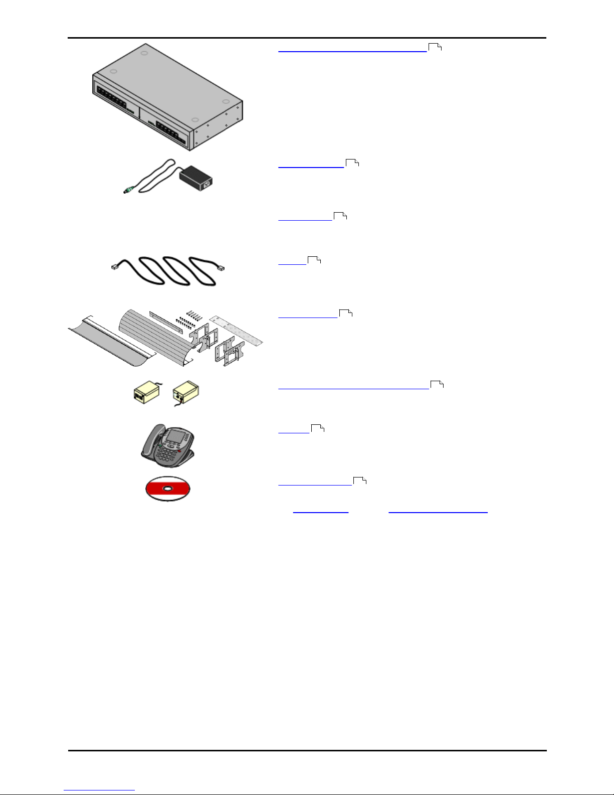
Deploying Avaya IP Office™ Platform IP500 V2 Page 20
15-601042 Issue 30j (18 May 2015)IP Office™ Platform 9.1
Comments on this document? [email protected]
· IP500 External Expansion Modules
Additional ports can be added using a number of IP500 external
expansion modules.
· Systems running in IP Office Basic Edition modes support up
to 8 external expansion modules so long as the system
extensions limit is not exceeded.
· Systems running in IP Office standard modes support 8
external expansion modules or 12 if the control unit is fitted
with an IP500 4-Port Expansion Base Card.
· Power Supplies
The IP500 control unit has an internal power supply unit. Each
external expansion module is supplied with an external power
supply unit. Additional power supply units may also be required
for IP phones and some phone add-ons.
· Power Cords
Depending on the locale, different power cords need to be ordered
for each control unit, external expansion module and any phones
or devices using external power supply units.
· Cables
The system is designed primarily for connection to a structured
cabling system using CAT3 UTP cabling. This approach allows
telephone and data traffic to share the same wiring infrastructure
and simplifies equipment moves.
· Mounting Kits
The control unit can be used free-standing, with external
expansion modules stacked above it. With optional rack mounting
kits, the control unit and external expansion modules can also be
rack mounted. Alternatively with an optional wall mounting kit the
IP500 control unit can be wall mounted. IP500 external expansion
modules can also be wall mounted.
· Surge Protectors and Barrier Boxes
Where the installation includes extensions in other buildings
additional protective equipment is required. This equipment may
also be required in areas where the lightning risk is high.
· Phones
IP Office systems support a variety of Avaya digital and IP phones
plus analog phones.
· Application DVDs
The IP Office applications can be ordered on a number of DVDs.
In addition they can be downloaded from the IP Office section of
the Avaya support web site (http://support.avaya.com).
25
30
31
33
37
36
39
44
Page 21
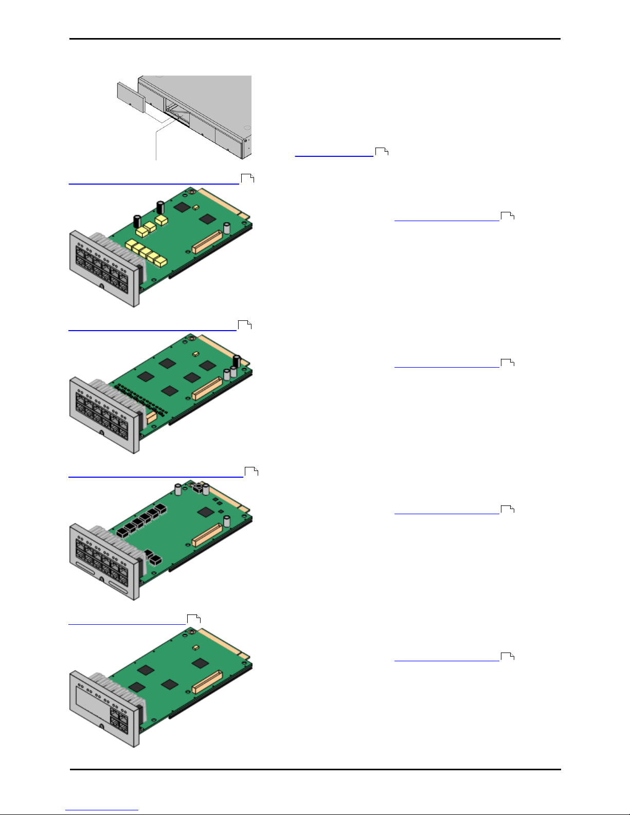
Deploying Avaya IP Office™ Platform IP500 V2 Page 21
15-601042 Issue 30j (18 May 2015)IP Office™ Platform 9.1
Comments on this document? [email protected]
System Overview: IP500 V2 System Components
1.7 Control Unit Cards
1.7.1 IP500 Base Cards
The IP500 V2 control unit has 4 slots for the insertion of IP500 base cards.
The slots are numbered 1 to 4 from left to right. Normally they can be
used in any order, however if the capacity for a particular type of card is
exceeded, the card in the rightmost slot will be disabled.
Each base card includes an integral front panel with ports for cable
connections. Typically the first 8 ports on the left are for connection of
extension devices. The 4 ports on the left are used for connection of
trunks if a trunk daughter card is added to the base card.
IP500 Digital Station Base Card
This card provides 8 DS (digital station) ports for the connection of
Avaya digital phones.
· The card can be fitted with an IP500 trunk daughter card which
uses the base card ports for trunk connection.
· Maximum: 3 per control unit.
· 4400 Series phones (4406D, 4412D and 4424D) are not
supported on this card. They are supported on external
expansion module DS ports.
· Connections for 4100, 7400, M-Series and T-Series phones use
the IP500 TCM8 Digital Station card.
IP500 Analog Phone Base Card
The card is available in two variants, supporting either 2 or 8 analog
phone ports.
· The card can be fitted with an IP500 trunk daughter card which
uses the base card ports for trunk connection.
· Maximum: 4 per control unit.
· The analog phone ports do not include a ringing capacitor.
Where this is a requirement, connection should be via a Master
socket containing ringing capacitors.
· If fitted with an IP500 Analog Trunk daughter card, during
power failure phone port 8 is connected to analog trunk port 12.
IP500 TCM8 Digital Station Card
This card provides 8 BST (digital station) ports for the connection of
Avaya 4100, 7400, M-Series and T-Series phones.
· The card can be fitted with an IP500 trunk daughter card which
uses the base card ports for trunk connection.
· Maximum: 4 per control unit per IP500 V2 control unit. Not
supported by IP500 control units.
IP500 VCM Base Card
This card is available in variants supporting either 32 or 64 voice
compression channels for use with VoIP calls.
· The card can be fitted with an IP500 trunk daughter card which
uses the base card ports for trunk connection.
· Maximum: 2 per control unit.
24
203
24
198
24
206
24
207
24
Page 22

Deploying Avaya IP Office™ Platform IP500 V2 Page 22
15-601042 Issue 30j (18 May 2015)IP Office™ Platform 9.1
Comments on this document? [email protected]
IP500 4-Port Expansion Base Card
This card adds an additional 4 expansion ports for external expansion modules.
The card is supplied with four 2m yellow interconnect cables.
· This card does not accept any IP500 trunk daughter card.
· Maximum: 1 per control unit (Right-hand slot 4 only).
· Supported Expansion Modules: The following external expansion modules
are supported:
· IP500 Analogue Trunk Module
· IP500 BRI So Module
· IP500 Digital Station Module
· IP500 Digital Station Module A
· IP500 Digital Station Module B
· IP500 Phone Module
IP500 BRI Combination Card
This card provides 6 digital station ports (1-6), 2 analog extension
ports (7-8) and 2 BRI trunk ports (9-10, 4 channels). The card also
includes 10 voice compression channels.
· This card has a pre-installed IP500 BRI trunk daughter card .
· Maximum: 2 combination cards per IP500 V2 control unit,
regardless of type.
· IP Office Basic Edition - Norstar Mode and IP Office Basic Edition
systems are limited to a maximum of 12 BRI channels using BRI
Combination and or BRI trunk daughter cards.
IP500 ATM Combination Card/IP500 ATM Combination Card V2
This card provides 6 digital station ports (1-6), 2 analog extension
ports (7-8) and 4 analog trunk ports (9-12). The card also includes 10
voice compression channels.
· This card has a pre-installed IP500 analog trunk daughter card .
· Maximum: 2 combination cards per IP500 V2 control unit,
regardless of type.
· The analog phone ports do not include a ringing capacitor.
Where this is a requirement, connection should be via a Master
socket containing ringing capacitors.
· If fitted with an IP500 Analog Trunk daughter card, during
power failure phone port 8 is connected to analog trunk port 12.
IP500 ETR6 Base Card
This card is only supported in an IP500 V2 control unit running in IP
Office Basic Edition - PARTNER® Mode or IP Office Basic Edition. It
provides 6 ETR ports for connection of ETR phones. 2 Analog extension
ports are also provided for emergency use only with an analog trunk
card.
· The card can be fitted with an IP500 trunk daughter card which uses
the base card ports for trunk connection.
· Maximum: 3 per IP500 V2 control unit.
· The analog phone ports do not include a ringing capacitor. Where
this is a requirement, connection should be via a Master socket
containing ringing capacitors.
· If fitted with an IP500 Analog Trunk daughter card, during power
failure phone ports 7 and 8 are connected to analog trunk port 12.
However during normal operation analog phone ports 7 and 8 are
not useable.
Unified Communications Module
197
201
24
199
24
204
202
Page 23
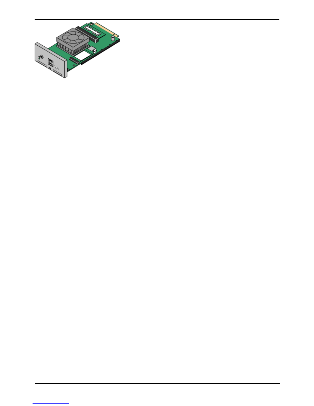
Deploying Avaya IP Office™ Platform IP500 V2 Page 23
15-601042 Issue 30j (18 May 2015)IP Office™ Platform 9.1
Comments on this document? [email protected]
System Overview: Control Unit Cards
This card acts as an embedded Linux server for the one-X Portal for IP
Office and/or Voicemail Pro applications.
Page 24
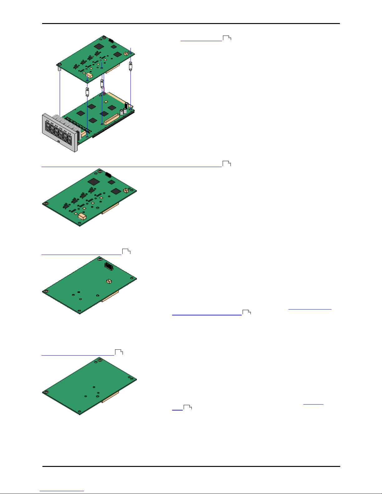
Deploying Avaya IP Office™ Platform IP500 V2 Page 24
15-601042 Issue 30j (18 May 2015)IP Office™ Platform 9.1
Comments on this document? [email protected]
1.7.2 IP500 Trunk Cards
Many IP500 base cards can be fitted with an IP500 trunk
daughter cards to support the connection of trunks to the base card.
Each daughter card is supplied with the stand off pillars required for
installation and a label to identify the daughter cards presence on
the front of the base card after installation.
· IP500 Combination cards are pre-fitted with a trunk daughter card
which cannot be removed or changed for another type of trunk
daughter card.
IP500 Analog Trunk Card/IP500 Analog Trunk Card V2
These cards allow the base card to support 4 analog loop-start
trunks.
· The analog phone ports do not include a ringing capacitor.
Where this is a requirement, connection should be via a
Master socket containing ringing capacitors.
· If fitted with an IP500 Analog Trunk daughter card, during
power failure phone port 8 is connected to analog trunk port
12.
· Maximum: 4 per control unit. The IP500 Analog Trunk Card V2 is
only supported in the IP500 V2.
IP500 PRI-U Trunk Card
This card allows the base card to support up to 2 PRI trunk
connections. The card is available in single and dual port variants.
The card can be configured for E1 PRI, T1 robbed bit, T1 PRI or
E1R2 PRI trunks. A T1(J) variant for use in Japan is also available.
· Maximum: 4 per control unit.
· The IP Office system supports 8 unlicensed B-channels on each
IP500 PRI-U port fitted. Additional B-channels, up to the capacity
of ports installed and PRI mode selected require IP500 Universal
PRI (Additional Channels) licenses added to the
configuration. These additional channels consume the licenses
based on which additional channels are configured as in-service
from port 9 of slot 1 upwards. D-channels are not affected by
licensing.
IP500 BRI Trunk Card
This card allows the base card to support up to 4 BRI trunk
connections, each trunk providing 2B+D digital channels. The card is
available in 2 port (4 channels) and 4 port (8 channels) variants.
· Maximum: 4 per control unit.
· S-Bus Connection: The card can be switched from To trunk
mode to So mode. This mode requires additional terminating
resistors and an ISDN crossover cable connection, see BRI Port
(So) .
· IP Office Basic Edition - Norstar Mode and IP Office Basic
Edition systems are limited to a maximum of 12 BRI channels
using BRI Combination and or BRI trunk daughter cards.
21
210
213
364
212
350
Page 25
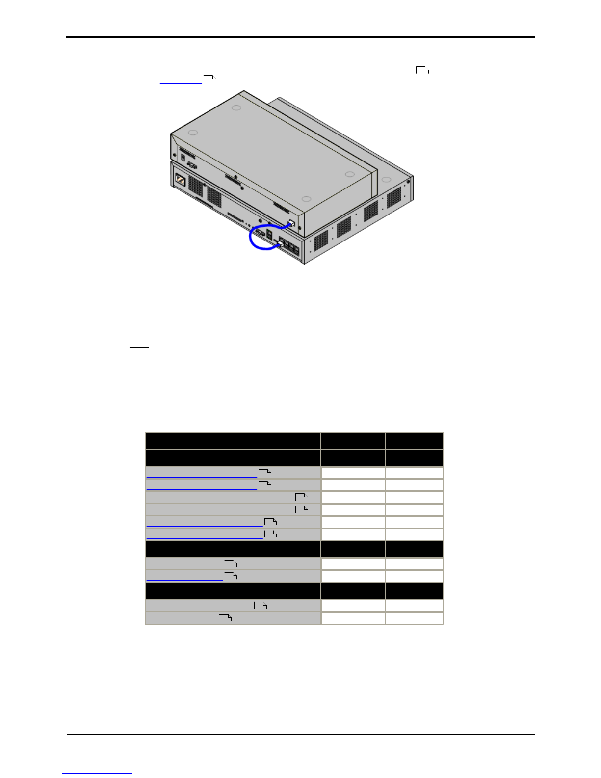
Deploying Avaya IP Office™ Platform IP500 V2 Page 25
15-601042 Issue 30j (18 May 2015)IP Office™ Platform 9.1
Comments on this document? [email protected]
System Overview: Control Unit Cards
1.8 External Expansion Modules
These modules can be used to add additional ports to an IP Office systems. The number of external expansion modules
supported depends on the control unit type. Each module uses an external power supply unit supplied with the
module. A locale specific power cord for the PSU must be ordered separately.
IP500 System with External Expansion Module
· Systems running in IP Office Basic Edition modes support up to 8 external expansion modules so long as the
system extensions limit is not exceeded.
· Systems running in IP Office standard modes support 8 external expansion modules or 12 if the control unit is
fitted with an IP500 4-Port Expansion Base Card.
· Each external expansion module is supplied with a blue 1 meter (3'3'') expansion interconnect cable. This
cable must be used when connecting to expansion ports on the rear of a control unit.
· When connecting to expansion ports on an IP500 4-Port Expansion card, a yellow 2 meter (6'6") expansion
interconnect cable can be used in place of the standard blue cable. 4 Yellow cables are supplied with the IP500
4-Port Expansion card.
IP500 External Expansion Modules
Expansion modules include an external power supply unit (PSU) and a 1m blue interconnect cable. They do not include a
locale specific power cord for the external PSU or any phone extension cables.
Variant
Country
SAP Code
Digital Phones (Non-IP)
IPO 500 Digital Station 16
All
700449499
IPO 500 Digital Station 30
All
700426216
IPO 500 Digital Station 16A (RJ21)
All
700500699
IPO 500 Digital Station 30A (RJ21)
All
700500698
IPO 500 Digital Station 16B
All
700501585
IPO 500 Digital Station 30B
All
700501586
Analog Phones
IPO 500 Phone 16
All
700449507
IPO 500 Phone 30
All
700426224
Others
IPO 500 Analog Trunk 16
US
700449473
IPO 500 BRI So8
All
700449515
30
31
220
220
222
225
225
225
227
227
216
218
Page 26
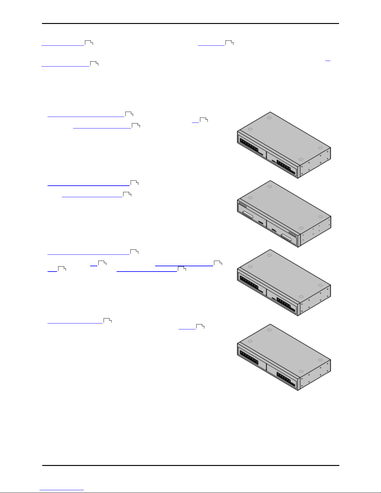
Deploying Avaya IP Office™ Platform IP500 V2 Page 26
15-601042 Issue 30j (18 May 2015)IP Office™ Platform 9.1
Comments on this document? [email protected]
1.8.1 IP500 External Expansion Modules
The following IP500 external expansion modules are supported by IP Office Release 9.1. Each module uses an external
power supply unit supplied with the module. A locale specific power cord for the PSU must be ordered
separately.
The external module can be stacked on top of the control unit. They can also be wall or rack mounted using one of the IP
Office mounting kits .
· Systems running in IP Office Basic Edition modes support up to 8 external expansion modules so long as the
system extensions limit is not exceeded.
· Systems running in IP Office standard modes support 8 external expansion modules or 12 if the control unit is
fitted with an IP500 4-Port Expansion Base Card.
· IP500 Digital Station Module
Provides, depending on variant, an additional 16 or 30 RJ45 DS ports for
supported Avaya DS digital phones .
· IP500 Digital Station A Module
Provides, depending on variant, RJ21 ports for connection of an additional 16
or 30 Avaya BST digital phones . Supported by IP500 V2 only.
· IP500 Digital Station B Module
Provides, depending on variant, an additional 16 or 30 RJ45 ports. These can
be used as either DS ports for supported Avaya DS digital phones or
BST ports for supported Avaya BST digital phones . However, the
module can only support one port type at any time.
· IP500 Phone Module
Provides, depending on variant, an additional 16 or 30 PHONE ports for
connecting analog phones.
30 31
238
220
353
39
222
39
225
353 39
352 39
227
358
Page 27
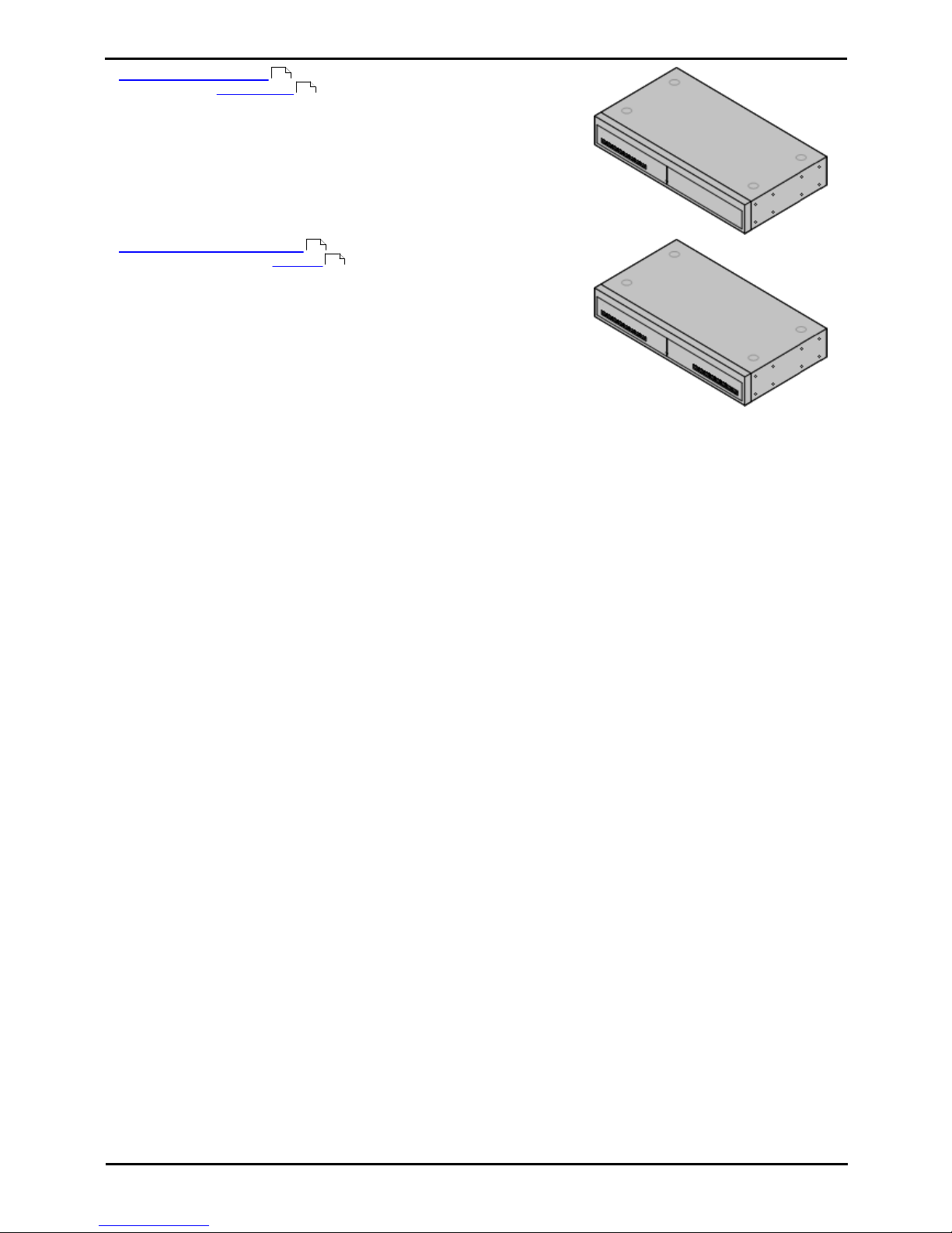
Deploying Avaya IP Office™ Platform IP500 V2 Page 27
15-601042 Issue 30j (18 May 2015)IP Office™ Platform 9.1
Comments on this document? [email protected]
System Overview: External Expansion Modules
· IP500 BRI So8 Module
Provides 8 ETSI BRI-So ports for the connection of ISDN devices. This unit
is not intended to support BRI trunks.
· IP500 Analog Trunk Module
Provides an additional 16 ANALOG ports for connection of analog trunks.
Supports both loop-start and ground-start trunks.
· Use with ground start trunks requires that the trunk module and the IP
Office control unit are grounded.
· In IP Office Basic Edition - PARTNER® Mode, IP Office Basic Edition - Norstar
Mode and IP Office Basic Editions, only 1 Analog Trunk module is supported.
218
350
216
349
Page 28
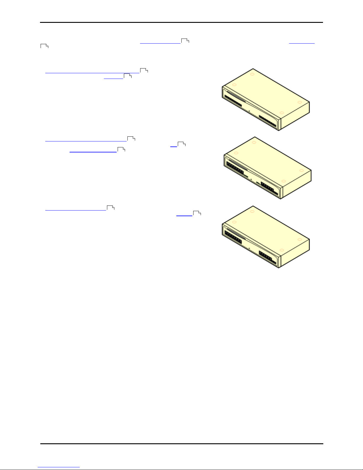
Deploying Avaya IP Office™ Platform IP500 V2 Page 28
15-601042 Issue 30j (18 May 2015)IP Office™ Platform 9.1
Comments on this document? [email protected]
1.8.2 IP400 External Expansion Modules
The following IP400 external expansion modules are supported by IP Office Release 9.1 and can be used with IP500 V2
control units. Each module uses an external power supply unit supplied with the module. A locale specific power cord
for the PSU must be ordered separately.
If being rack mounted these units use the IP400 rack mounting kit. If being rack mounted, these units use the IPO IP500
RACK MNTG KIT. They cannot be wall mounted.
· IP400 Analog Trunk Module (ATM16)
Provides an additional 16 ANALOG ports for connection of analog trunks.
Supports both loop-start and ground-start trunks.
· Available in a number of variants for different locales.
· Use with ground start trunks requires that the trunk module and the IP
Office control unit are grounded.
· IP400 Digital Station Module V2
Provides, depending on variant, an additional 16 or 30 DS ports for
supported Avaya digital phones . Supersedes the previous Digital Station
module.
· IP400 Phone Module V2
Provides, depending on variant, an additional 8, 16 or 30 PHONE ports
for analog phones. Supersedes the previous Phone module. With IP Office
3.1, the Phone V2 supports a wider range of message waiting indication
(MWI) options than Phone V1 modules.
30
31
230
349
232
353
39
234
358
Page 29
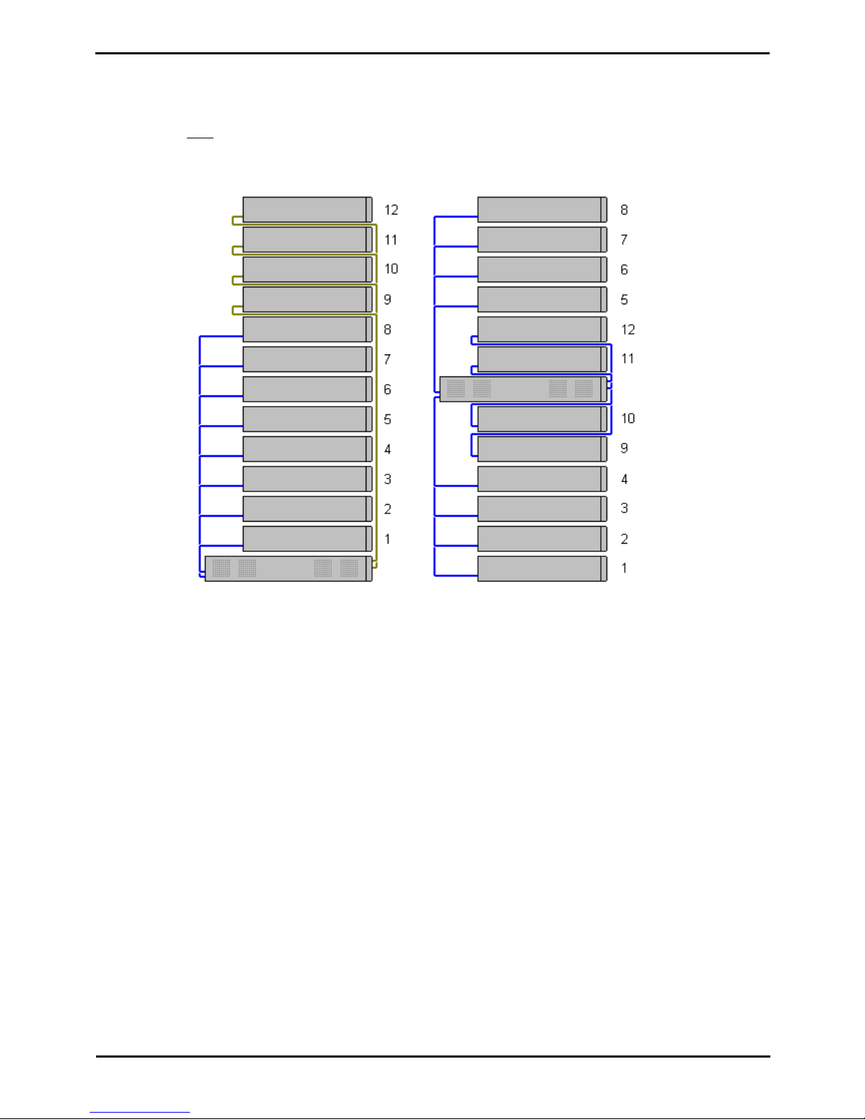
Deploying Avaya IP Office™ Platform IP500 V2 Page 29
15-601042 Issue 30j (18 May 2015)IP Office™ Platform 9.1
Comments on this document? [email protected]
System Overview: External Expansion Modules
1.8.3 Connecting External Expansion Modules
The integral expansion ports on a control unit are located on the rear of the unit. For IP500 V2 control units, an additional
4 expansion ports can be added to the front of the control unit by installing an IP500 4-Port Expansion card.
· Each external expansion module is supplied with a blue 1 meter (3'3'') expansion interconnect cable. This
cable must be used when connecting to expansion ports on the rear of a control unit.
· When connecting to expansion ports on an IP500 4-Port Expansion card, a yellow 2 meter (6'6") expansion
interconnect cable can be used in place of the standard blue cable. 4 Yellow cables are supplied with the IP500
4-Port Expansion card.
Page 30
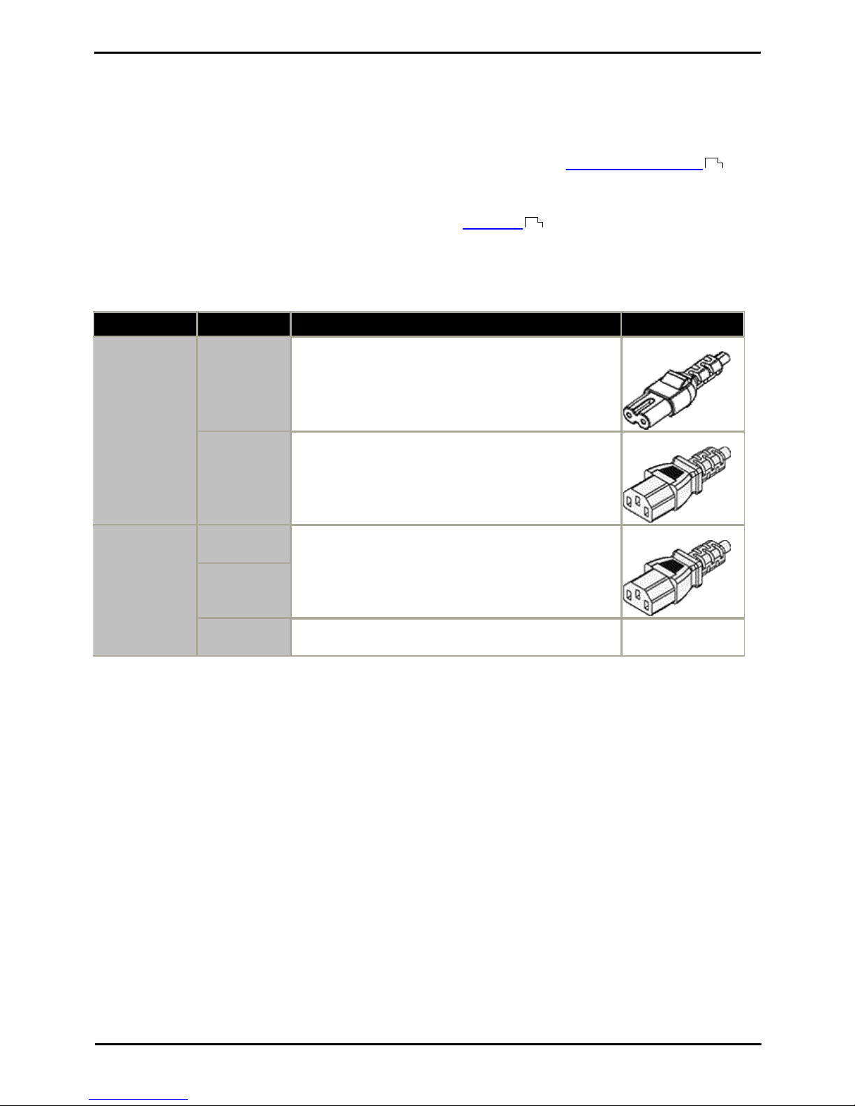
Deploying Avaya IP Office™ Platform IP500 V2 Page 30
15-601042 Issue 30j (18 May 2015)IP Office™ Platform 9.1
Comments on this document? [email protected]
1.9 Power Supplies and Cables
All IP Office control units and external expansion modules either have an internal power supply unit or are supplied with
an external power supply unit.
1.9.1 Power Supplies
IP500 V2 control units have an internal power supply unit and so only require a suitable locale specific power cord
and a power outlet that includes a switch. Note that if the power cord includes an earth lead, the power outlet must be
connected to a protective earth.
External expansion modules are all supplied with an external power supply unit (PSU). These PSUs include an integral 1.5
meter lead for connection to the control unit or expansion module. A power cord for connection from the PSU to the
power outlet is not included as this varies by locale. The appropriate power cord must be ordered separately or sourced
locally.
Additional power supply units are required for 4450, EU24, XM24 and T3 DSS add-on modules and may also be required
for Avaya IP phones.
Area
Type
Used on:
Connector Type
IP Office Control
Units and
External
Expansion
Modules
40W PSU
Analog, Digital Station V1, Phone V1.
IEC60320 C7
60W Earthed
PSU
IP500 Phone 30, IP500 Digital Station 30, IP500 Digital
Station 16A, IP500 Digital Station 30A.
IEC60320 C13
IP Phones and
Phone Add-Ons
1151D1
All phones with XM24 Phone add-ons.
All phones with EU24/EU24BL Phone add-ons unless using
Class 3 PoE.
4600 and 56000 Series IP Phones when not using a PoE.
IEC60320 C13
1151D2
1600PWR 5V
Plug-top PSU used with 1600 Series phones on IP Office
when not being power using PoE.
Various country
variants.
· The 1151D2 is the same as the 1151D1 except that it includes a backup battery that is charged during normal
operation. This can provide typically 15 minutes backup at maximum load (20 Watts) and up to 8 hours at light
load (2 Watts).
· Avaya IP phones can use IEEE 802.3af Power over Ethernet (PoE) power supplies. Refer to the IP Office IP Phone
Installation Manual for full details.
31
31
Page 31
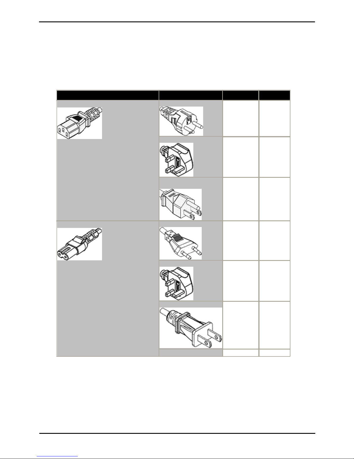
Deploying Avaya IP Office™ Platform IP500 V2 Page 31
15-601042 Issue 30j (18 May 2015)IP Office™ Platform 9.1
Comments on this document? [email protected]
System Overview: Power Supplies and Cables
1.9.2 Power Supply Cords
Each control unit and expansion module requires a switched power outlet socket rated at 110-240V ac, 50-60Hz.
Connection from that power outlet socket requires an appropriate locale specific power cord which is not supplied with
the unit and must be ordered separately. Note that if the power cord includes an earth lead, the power outlet must be
connected to a protective earth.
Power cords must not be attached to the building surface or run through walls, ceilings, floors and similar openings.
Installation measures must be taken to prevent physical damage to the power supply cord, including proper routing of
the power supply cord and provision of a socket outlet near the fixed equipment or positioning of the equipment near a
socket outlet.
For locales not detailed below an appropriate power cord must be obtained locally.
Power Cord Type
Power Outlet Plug Type
Locales
SAP Codes
Earthed Power Cords (IEC60320 C13)
Control Units
· IP500 V2.
IP500 External Expansion Modules
· BRI So8.
· Digital Station 16/30.
· Phone 16/30.
CEE7/7 (Schuko)
Europe and
South Africa.
700289762
BS1363
Czech Republic,
Ireland, United
Kingdom.
700289747
NEMA5-15P / CS22.2
No.42
North, Central
and South
America.
700289770
Unearthed Power Cord (IEC60320 C7)
IP500 External Expansion Modules
· Analog Trunk 16.
CEE7/16 (Europlug)
Europe and
South Africa.
700213382
BS1363
Czech Republic,
Ireland, United
Kingdom.
700213374
NEMA1-15
North, Central
and South
America.
700213390
Korea.
700254519
Page 32

Deploying Avaya IP Office™ Platform IP500 V2 Page 32
15-601042 Issue 30j (18 May 2015)IP Office™ Platform 9.1
Comments on this document? [email protected]
1.9.3 Power Supply Backup
The use of an Uninterrupted Power Supply (UPS) with any telephone system is strongly recommended. Even at sites that
rarely lose electrical power, that power may occasionally have to be switched off for maintenance of other equipment. In
addition, most UPSs also provide an element of power conditioning, reducing spikes and surges.
The capacity of UPS systems and the total equipment load the UPS is expected to support are usually quoted in VA.
Where equipment load is quoted in Watts, multiply by 1.4 to get the VA load.
The calculation of how much UPS capacity is required depends on several choices.
· What equipment to place on the UPS?
Remember to include server PCs such as the voicemail. It is recommended that the total load on a new UPS is
never greater than 75% capacity, thus allowing for future equipment.
· How many minutes of UPS support is required?
Actual UPS runtime is variable, it depends on what percentage of the UPS capacity the total equipment load
represents. For example, a 1000VA capacity UPS may only support a 1000VA (100%) load for 5 minutes. This
relationship is not linear, the same UPS may support a 500VA (50%) load for 16 minutes. Therefore, the lower the
percentage of maximum capacity used, the increasingly longer the UPS runtime, for example up to 8 hours.
· How frequent are the power loses?
You also need to include allowance for the UPS recharge time. For most UPS's the ratio of discharge to full
recharge time is 1:10.
· How many output sockets does the UPS provide?
Multiple UPS units may be required to ensure that every item of supported equipment has its own supply socket.
Example Values
The dominate factor in the power consumption of an IP Office system is the telephones attached to the control unit and
any external expansion modules. This does not include IP telephones which require their own separate power supplies. If
any server PCs are being used by the system, the requirements of those PCs should also be included in the assessment.
Similarly support for adjunct systems such as DECT should be considered.
The following are worst case figures tested found using fully populated control units and external expansion modules:
· IP500 V2 Control Unit: 115W.
· IP500 Digital Station 16 External Expansion Module: 31W.
· IP500 Digital Station 30 External Expansion Module: 56W.
· IP500 DS16A Digital Station RJ21 External Expansion Module: 34W.
· IP500 DS30A Digital Station RJ21 External Expansion Module: 60W.
· IP500 Phone 16 External Expansion Module: 25W.
· IP500 Phone 30 External Expansion Module: 45W.
· IP500 Analog Trunk Module 16 External Expansion Module: 8.8W.
Page 33
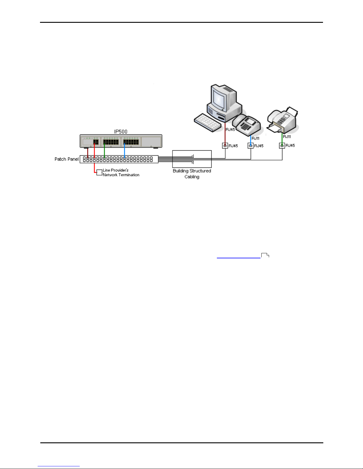
Deploying Avaya IP Office™ Platform IP500 V2 Page 33
15-601042 Issue 30j (18 May 2015)IP Office™ Platform 9.1
Comments on this document? [email protected]
System Overview: Power Supplies and Cables
1.9.4 Cabling and Cables
The IP Office systems are designed primarily for use within an RJ45 structured cabling system using CAT3 unshielded
twisted-pair (UTP) cabling and RJ45 sockets.
A structured cabling system is one where cables are run from a central RJ45 patch panel in the communications/data
room to individual RJ45 sockets at user locations. All wires in each cable between the patch panel and the desk socket
are connected straight through. This arrangement allows devices connected at the patch panel to be swapped to match
the type of device that needs to be connected at the user socket. For example, making one user socket a phone port and
another user socket a computer LAN port, without requiring any rewiring of the cables between the patch panel and the
user location.
· Traditional IDC Punchdown Wiring Installations
Where necessary, the far end RJ45 plug can be stripped from IP Office cables and wired into traditional wiring
systems using punch-block connectors. This type of installation should be performed by an experienced wiring
technician.
· Trunk Connections
The majority of IP Office trunk ports use RJ45 connectors for acceptance of an RJ45-to-RJ45 cable. However,
connection at the line provider's end may require use of a different plug type in order to match the line providers
equipment.
· RJ11 Phone Connectors
Many phones use RJ11 sockets and are supplied with RJ11-to-RJ11 cables. RJ11 plugs can be inserted into RJ45
sockets and in many case the connection will work. However this is not recommended or supported as the
connection lock is not truly positive and may become disconnected. An RJ45-to-RJ11 cable is available for
these connections.
353
Page 34
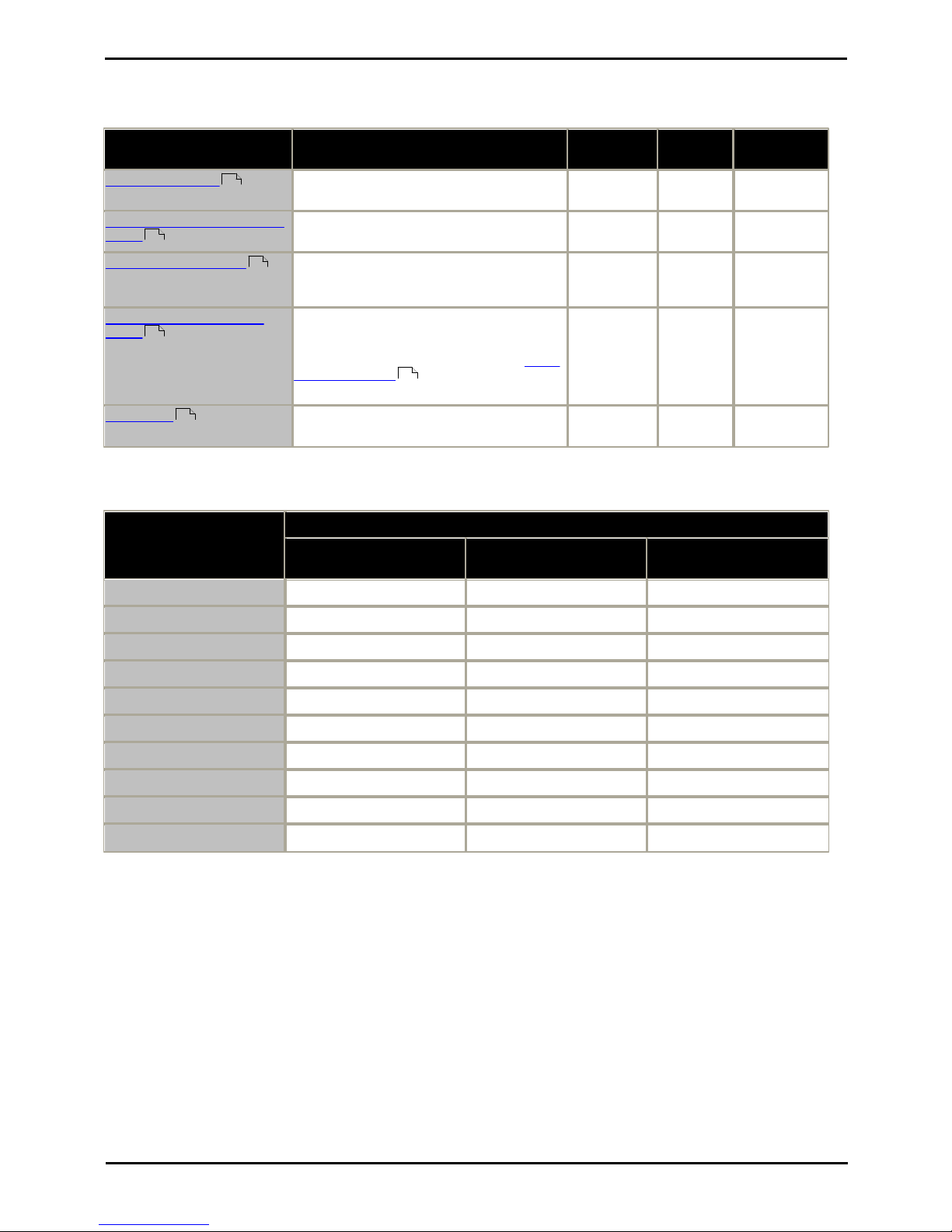
Deploying Avaya IP Office™ Platform IP500 V2 Page 34
15-601042 Issue 30j (18 May 2015)IP Office™ Platform 9.1
Comments on this document? [email protected]
Standard IP Office Cables
The following are Avaya standard cables available for use with IP Office systems. The maximum length is applicable if the
standard Avaya cable is replaced with an alternate cable.
Cable
Description
SAP Code
Standard
Length
Maximum
Length
9-Way DTE Cable
Connects to control unit RS232 DTE port. 9Way D-type plug to 9-way D-type socket.
–
2m/6'6''.
2m/6'6''.
Structured Cabling DS Line
Cable
Connects from RJ45 sockets to RJ11
socketed DS and analog phones.
TT700047871
4m/13'2''.
See table
below.
BRI/PRI Trunk Cable
Connects BRI/PRI trunk ports to the line
provider's network termination point. RJ45 to
RJ45. Red.
700213440
3m/9'10''.
–
Expansion Interconnect
Cable
Connects the control unit to expansion
modules. RJ45 to RJ45. Blue. May be
replaced by a yellow interconnect cable (2m
(6'6") - 700472871) supplied with the IP500
4-Port Expansion card when using that
card.
700213457
1m/3'3''.
1m/3'3''.
LAN Cable
Connects from IP Office LAN ports to IP
devices. RJ45 to RJ45. Grey.
700213481
3m/9'10''.
100m/328'.
The table below details the maximum total cable distances for DS and analog extensions using different cable
thicknesses. Cabling should be Category-1 unshielded twisted pair cable or better.
Telephone
Unshielded Twisted-Pair (UTP) - 50nf/Km
AWG22
(0.65mm)
AWG24
(0.5mm)
AWG26
(0.4mm)
1400 Series
1200m/3937'.
1000m/3280'.
670m/2200'.
2400/5400 Series
1200m/3937'.
1000m/3280'.
670m/2200'.
4406D Phone
1000m/3280'.
1000m/3280'.
400m/1310'.
4412D Phone
1000m/3280'.
700m/2295'.
400m/1310'.
4424D
500m/1640'.
500m/1640'.
400m/1310'.
9500 Series
1200m/3937'.
1000m/3280'.
670m/2200'.
T3 Series
1000m/3280'.
1000m/3280'.
400m/1310'.
BST
580m/1900'.
365m/1200'
228m/750'
Analog Phones
1000m/3280'.
1000m/ 3280'.
400m/1640'.
ETR Phones
305m/1000'.
305m/1000'.
122m/400'.
360
353
351
355
197
356
Page 35

Deploying Avaya IP Office™ Platform IP500 V2 Page 35
15-601042 Issue 30j (18 May 2015)IP Office™ Platform 9.1
Comments on this document? [email protected]
System Overview: Power Supplies and Cables
1.9.5 Grounding
All IP Office control units and external expansion modules must be connected to a functional ground. Where the unit is
connected to a power outlet using a power cord with an earth lead, the power outlet must be connected to a protective
earth.
Use of ground connections reduces the likelihood of problems in most telephony and data systems. This is especially
important in buildings where multiple items of equipment are interconnected using long cable runs, for example phone
and data networks.
In some cases, such as ground start trunks, in addition to being a protective measure, this is a functional requirement for
the equipment to operate. In other cases it may be a locale regulatory requirement and or a necessary protective step,
for example areas of high lightning risk.
· WARNING
During installation do not assume that ground points are correctly connected to ground. Test ground points before
relying on them to ground connected equipment.
The ground point on IP Office control units and external expansion modules are marked with a or symbol. Ground
connections to these points should use a 14 AWG solid wire with either a green sleeve for a functional ground or green
and yellow sleeve for a protective ground.
· Additional protective equipment
In addition to grounding, additional protective equipment will be required in the following situations. Refer to "Out
of Building Telephone Installations ".
· On any Digital Station or Phones external expansion module connected to an extension located in another
building.
· In the Republic of South Africa, on all Analog Trunk external expansion modules (ATM16) and on any control
units containing an analog trunk cards (ATM4/ATM4U).
36
Page 36
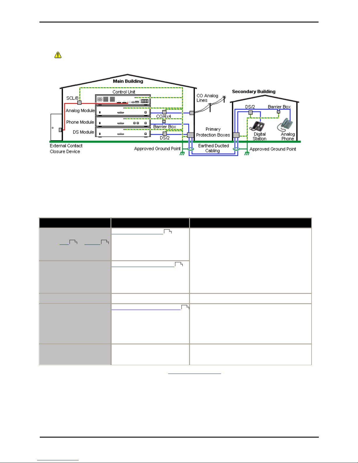
Deploying Avaya IP Office™ Platform IP500 V2 Page 36
15-601042 Issue 30j (18 May 2015)IP Office™ Platform 9.1
Comments on this document? [email protected]
1.9.6 Lightning Protection/Out-of-Building Connections
The following are the only supported scenarios in which wired extensions and devices outside the main building can be
connected to the IP Office system. In these scenarios, additional protection, in the form of protective grounding and
surge protectors, must be fitted.
· WARNING
The fitting of additional protection does not remove the risk of damage. It merely reduces the chances of
damage.
· Cables of different types, for example trunk lines, phone extensions, ground and power connections, should be
kept separate.
· All cabling between buildings should be enclosed in grounded ducting. Ideally this ducting should be buried.
· A Primary Protection Box must be provided at the point where the cables enter the building. This should be three
point protection (tip, ring and ground). Typically this would be gas tube protection provided by the local telephone
company. The ground wire must be thick enough to handle all the lines being affected by indirect strike at the
same time.
Connection Type
Protection Device Type
Requirement
Analog Phone Extensions
Phones External expansion
module (POT or PHONE )
ports only.
IP Office Barrier Box
Supports a single connection.
Maximum of 16 on any expansion
module.
· Connection from the expansion module to the
phone must be via a surge protector at each end
and via the primary protection point in each
building.
· The IP Office external expansion modules, control
unit and IROB devices must be connected to the
protective ground point in their building.
· The between building connection must be via
earthed ducting, preferable underground. The
cable must not be exposed externally at any point.
DS Phone Extensions
ITWLinx towerMAX DS/2
Supports up to 4 connections.
This device was previously
referred to as the Avaya 146E.
BST Phone Extensions
None
Currently not supported.
Analog Trunks
ITWLinx towerMAX CO/4x4
Supports up to 4 two-wire lines.
This device was previously
referred to as the Avaya 146C.
For installations in the Republic of South Africa, the
fitting of surge protection on analog trunks is a
requirement.
For other locations where the risk of lightning strikes
is felt to be high, additional protection of incoming
analog trunks is recommended.
External Output Switch
ITWLinx towerMAX SCL/8
This device was previously
referred to as the Avaya 146G.
Connections from an IP Office Ext O/P port to an
external relay device must be via a surge protector.
The towerMAX range of devices are supplied by ITWLinx (http://www.itwlinx.com).
358 358
172
171
171
Page 37
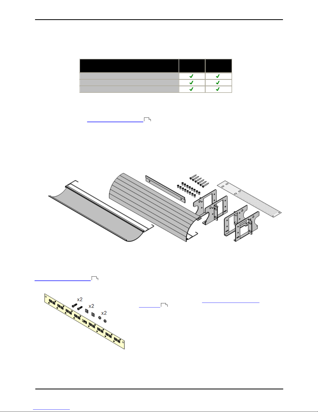
Deploying Avaya IP Office™ Platform IP500 V2 Page 37
15-601042 Issue 30j (18 May 2015)IP Office™ Platform 9.1
Comments on this document? [email protected]
System Overview: Power Supplies and Cables
1.10 Wall and Rack Mounting
All the IP Office control units are designed to be free-standing. On systems with external expansion modules, the control
unit and modules are intended to be stacked.
Using additional option mounting kits, some systems can be wall or rack mounted.
Control/Expansion Unit
Wall Mount
Rack
Mount
IP500 Control Unit
IP500 V2 Control Unit
IP500 External Expansion Modules
Wall Mounting
IP500 V2 control units and IP500 external expansion modules can be wall or rack mounted. To do this, a wall mounting
kit is required in addition to suitable wall fixings.
In addition to the existing environmental requirements for an IP Office system, the following additional requirements
apply when wall mounting a unit:
· The wall surface must be vertical, flat and vibration free. Attachment to temporary walls is not supported.
· Only the screws provided with the mounting kit should used to attach the brackets to the control unit.
The following wall and rack mounting kit is currently available:
· IPO IP500 RACK MNTG KIT V3 (SAP Code 700503160)
These kits can be used for wall and rack mounting of an IP500 V2 control unit and IP500 external expansion
modules. The kits incorporates cable routing at the front and rear of the unit. For wall mounted control units it
allows orientation of the control unit base card slots to the left or to the right.
Rack Mounting
All IP Office control units and external expansion modules can be rack mounted into standard 19" rack systems. Each unit
requires a 2U slot space within the rack. The IPO IP500 RACK MNTG KIT V3 is used for rack mounting of units.
Where IP Office systems are being rack mounted, the effect of conditions within the rack cabinet must be considered. For
example the rack temperature may be above the room temperature and airflow within the rack will be restricted. The
environmental requirements for the individual IP Office units are still applicable inside the rack cabinet.
Barrier Box Rack Mounting Kit
· Barrier Box Rack Mounting Kit (SAP 700293905)
Barrier boxes must be used for out-of-building analog phone
extensions . This bracket allows up to 8 IP Office barrier boxes to
be rack mounted and simplifies the number of connections to the
protective ground point in the rack. This kit must be used when more
than 3 barrier boxes are in use and supports a maximum of 16
barrier boxes for a single external expansion module.
52
52
36
Page 38

Deploying Avaya IP Office™ Platform IP500 V2 Page 38
15-601042 Issue 30j (18 May 2015)IP Office™ Platform 9.1
Comments on this document? [email protected]
1.11 Feature Keys and Licenses
A feature key is required for licensed features. For IP500 V2 systems the system SD card is used as the feature key.
· IP500 V2 Avaya SD Card
Inserts into the System slot on the rear of an IP500 V2 control unit. This card is required even if not
using any IP Office licenses.
Various IP Office features and applications require entry of licenses into the system's configuration. The licenses are
unique 32-character codes based on the feature being activated and the serial number of the System SD card
installed with the IP Office system. The serial number is printed on the System SD card and prefixed FK. It can also be
viewed in the system configuration using IP Office Manager.
When a license is entered into the IP Office configuration, the following information is shown.
· Status
The status, which is Unknown until the configuration file is sent back to the IP Office system.
· Unknown
This status is shown for licenses that have just been added to the configuration shown in IP Office Manager.
Once the configuration has been sent back to the IP Office and then reloaded, the status will change to one of
those below.
· Valid
The features licensed can be configured and used.
· Invalid
The license was not recognized. It did not match the serial number of the System SD card.
· Dormant
The license is valid but is conditional on some other pre-requisite that is not currently meet.
· Obsolete
The license is valid but is one no longer used by the level of software running on the system.
· Expired
The license has passed its expiry date.
· License
The name of the licensed feature. This may differ from the ordered RFA name.
· Instances
Depending on the license, this may be the number of ports enabled or number of simultaneous users of the
licensed feature. Sometime the number of instances is specified in the license name.
· Expires
Most purchased licenses have no expiry setting. For some features, trial licenses may be available which will have
an expiry date.
236
361
236
Page 39

Deploying Avaya IP Office™ Platform IP500 V2 Page 39
15-601042 Issue 30j (18 May 2015)IP Office™ Platform 9.1
Comments on this document? [email protected]
System Overview: Feature Keys and Licenses
1.12 IP Office Phones
IP Office Release 9.1 supports the following phones and phone add-ons. Availability may depend on location and may be
subject to local restrictions.
Enhanced Tip and Ring (ETR Ports)
These phones are only supported on an ETR6 card in a IP500 V2 systems. They are only supported in IP Office Basic
Edition - PARTNER® Mode and IP Office Basic Edition systems running a North American locale and U-Law companding.
· ETR Series: ETR6 , ETR6D , ETR18 , ETR18D , ETR34D (ETR 34D phones are limited to a
maximum of 2 per card and 4 in total)
· PARTNER DECT: 3910 , 3920
Avaya DS Digital Telephones (DS Ports)
These digital stations connect to the IP Office via DS ports. They are supported by all IP Office modes.
· 1400 Series: 1403 , 1408 , 1416
· 9500 Series: 9504 , 9508
The following additional DS port phones are only supported in IP Office standard modes:
· 2400 Series: 2402 , 2410 , 2420 .
· 3800 Series: 3810 Wireless phone (Only supported on external expansion modules).
· 4400 Series: 4406D , 4412D+ , 4424D+ (Only supported on external expansion modules).
· 5400 Series: 5402 , 5410 , 5420 .
· T3 Series: T3 Compact , T3 Classic , T3 Comfort .
Avaya BST Digital Telephones (BST Ports)
These digital stations connect to the IP500 V2 IP Office system via BST ports.
· 4100 Series: 4135, 4136, 4145, 4145EX, 4146, 4146EX - Connection to IP Office BST ports via a Digital Mobility
Solution system.
· 7400 Series: 7420, 7430, 7434, 7439, 7440, 7444, 7449 - Connection to IP Office BST ports via a Digital
Mobility Solution system.
· ACU: Audio Conferencing Unit
· M-Series: M7100 , M7100N , M7208 , M7208N , M7310 , M7310N , M7324 , M7324N .
· T-Series: T7000 , T7100 , T7208 , T7316 , T7316E , T7406 , T7406E
Analog Telephones
Analog phones and devices connect to PHONE ports with the IP Office system. However due to the variety of analog
phones and device available no guarantee of operation is given. It is the responsibility of the IP Office installer and
maintainer to test and verify the operation of proposed analog equipment. Analog message waiting indication (MWI) is
only supported with Avaya 6200 Series phones.
· 6200 Series: 6211, 6219, 6221 (North America).
· B100 Series: B149 , B159 , B169.
· Interquartz Gemini: 9330-AV, 9335-AV, 9281-AV (Europe, Middle East, Africa, Asia-Pacific).
IP Telephones
IP Phones (SIP and H323) connect to the IP Office system via the RJ45 LAN or WAN. These device require an Avaya IP
Endpoint license and voice compression resources. They are not supported in IP Office Basic Edition - PARTNER® Mode,
IP Office Basic Edition - Norstar Mode and IP Office Basic Edition mode.
H323:
· 1600 Series: 1603IP/SW , 1608 , 1608-I , 1616 , 1616-I
· 3600 Series: 3616 , 3620 , 3626 , 3641 , 3645
· 3700 Series: 3701 , 3711 - Connection via DECT base stations. 3720 , 3725 , 3740 , 3749 -
Connection via DECT R4 base stations.
· 4600 Series: 4601 , 4602 , 4602SW , 4610 , 4610SW , 4620 , 4620SW , 4621SW , 4625
.
· 5600 Series: 5601 , 5602 , 5602SW , 5610 , 5620 , 5621 .
· 9600 Series: 9608 , 9608G , 9611G , 9620L , 9620C , 9621G , 9630G , 9640 , 9640G
, 9641G , 9650 , 9650C .
· T3 IP Series: T3 IP Compact , T3 IP Classic , T3 IP Comfort .
SIP:
· 1000 Series: 1010 , 1040
· 1100 Series: 1120E , 1140E
304 304 305 305 306
267 267
353
243 244 245
285 286
252 253 254
266
268 269 270
277 278 279
318 316 317
331
331
300
307 307 308 308 309 309 310 310
311 311 312 313 314 315 315
358
301 301
246 248 248 250 250
255 256 257 258 259
260 261 262 263 264 265
271 272 272 273 273 274 274 275
276
280 281 281 282 283 284
287 287 288 290 290 292 293 295 295
297 298 298
318 316 317
241 241
242 242
Page 40

Deploying Avaya IP Office™ Platform IP500 V2 Page 40
15-601042 Issue 30j (18 May 2015)IP Office™ Platform 9.1
Comments on this document? [email protected]
· 1200 Series: 1220 , 1230
· B100 Series: B179 .
· D100 Series: These DECT handsets (up to 8) use a base station that connects to the IP Office system using a SIP
trunk and appear on the IP Office as SIP extensions.
· E129: A simple SIP telephone, the E129 support auto-answer, handsfree and headset operation.
· E169: A SIP telephone that supports the docking of mobile devices.
242 242
301
303
Page 41

Deploying Avaya IP Office™ Platform IP500 V2 Page 41
15-601042 Issue 30j (18 May 2015)IP Office™ Platform 9.1
Comments on this document? [email protected]
System Overview: IP Office Phones
1.13 VoIP
IP Office is a converged telephony system, that is it combines aspects of traditional PABX telephone systems and IP data
and telephony systems. This works at various levels.
· Individual phone users can control the operation of their phone through applications running on their PC.
· Data traffic can be routed from the LAN interface to a telephony trunk interface, for example a dial-up ISP
connection.
· Voice traffic can be routed across internal and external data links. This option is referred to as voice over IP
(VoIP).
The VoIP mode of operation can include external SIP trunks, IP trunks between customer systems and/or H.323 or SIP IP
telephones for users. In either case the following factors must be considered:
· The IP Office control unit must be fitted with voice compression channels . These are used whenever an IP
device (trunk or extension) needs to communicate with a non-IP device (trunk or extension) or to a device that
uses a different codec.
· A network assessment is a mandatory requirement for all systems using VoIP. For support issues with VoIP, Avaya
may request access to the network assessment results and may refuse support if those are not available or
satisfactory.
A network assessment would include a determination of the following:
· A network audit to review existing equipment and evaluate its capabilities, including its ability to meet both current
and planned voice and data needs.
· A determination of network objectives, including the dominant traffic type, choice of technologies, and setting
voice quality objectives.
· The assessment should leave you confident that the implemented network will have the capacity for the foreseen
data and voice traffic, and can support H.323, DHCP, TFTP and jitter buffers in H.323 applications.
· An outline of the expected network assessment targets is:
Test
Minimum Assessment Target
Latency
Less than 150ms.
Packet Loss
Less than 3%.
Duration
Monitor statistics once every minute for a full week.
42
Page 42
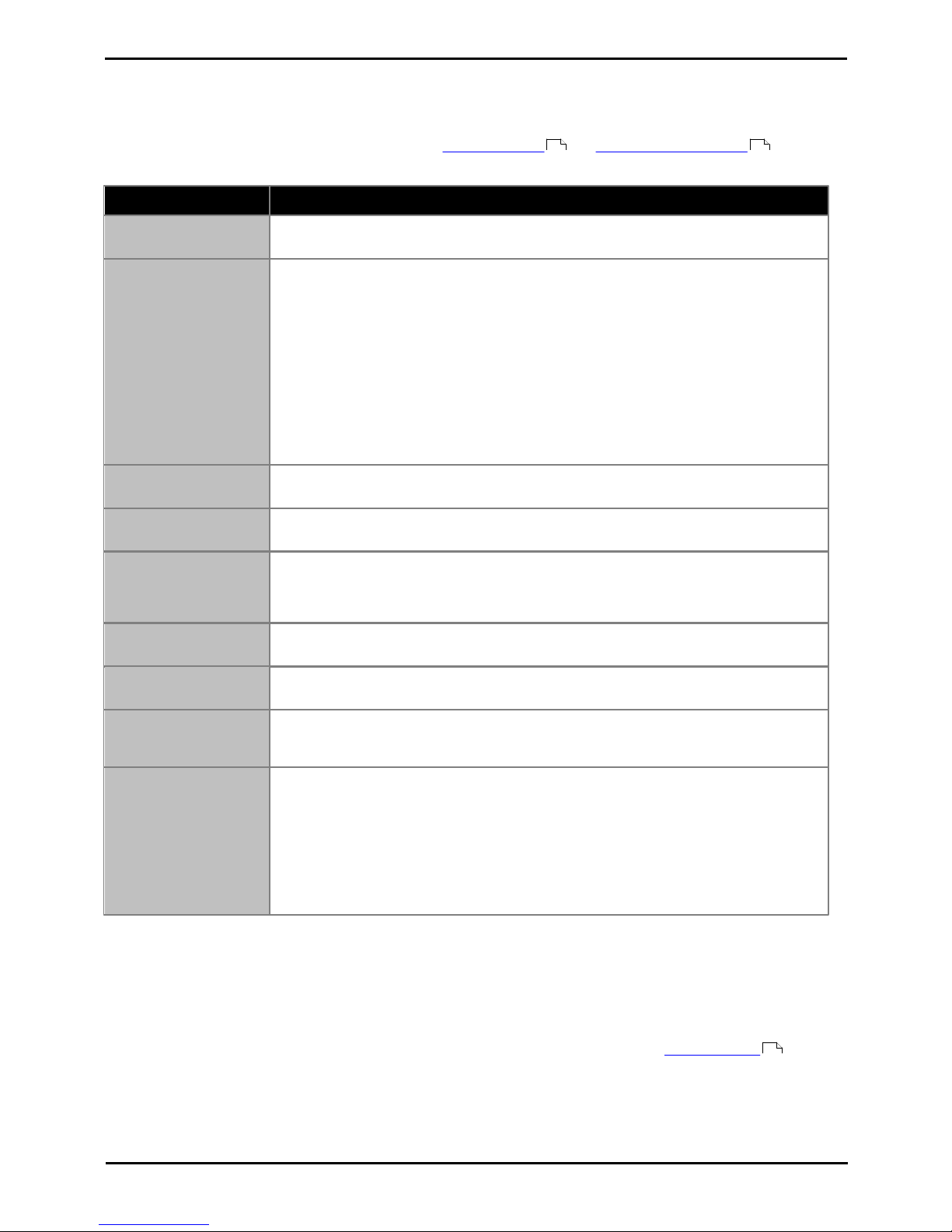
Deploying Avaya IP Office™ Platform IP500 V2 Page 42
15-601042 Issue 30j (18 May 2015)IP Office™ Platform 9.1
Comments on this document? [email protected]
1.13.1 Voice Compression Channels
Calls to and from IP devices can require conversion to the audio codec format being used by the IP device. For IP Office
systems this conversion is done by voice compression channels. These support the common IP audio codecs G.711,
G.723 and G.729a. For IP Office Release 8.0 and higher, IP500 VCM and IP500 Combination cards also support G.722.
For IP500 V2 control units, channels can be added using IP500 VCM cards and IP500 Combination Cards .
The voice compression channels are used as follows:
Call Type
Voice Compression Channel Usage
IP Device to Non-IP
Device
These calls require a voice compression channel for the duration of the call. If no channel is
available, busy indication is returned to the caller.
IP Device to IP Device
Call progress tones (for example dial tone, secondary dial tone, etc) do not require voice
compression channels with the following exceptions:
· Short code confirmation, ARS camp on and account code entry tones require a voice
compression channel.
· Devices using G723 require a voice compression channel for all tones except call
waiting.
When a call is connected:
· If the IP devices use the same audio codec no voice compression channel is used.
· If the devices use differing audio codecs, a voice compression channel is required for
each.
Non-IP Device to NonIP Device
No voice compression channels are required.
Music on Hold
This is provided from the IP Office's TDM bus and therefore requires a voice compression
channel when played to an IP device.
Conference Resources
and IP Devices
Conferencing resources are managed by the conference chip which is on the IP Office's TDM
bus. Therefore, a voice compression channel is required for each IP device involved in a
conference. This includes services that use conference resources such as call listen,
intrusion, call recording and silent monitoring.
Page Calls to IP Device
IP Office 4.0 and higher only uses G729a for page calls, therefore only requiring one channel
but also only supporting pages to G729a capable devices.
Voicemail Services and
IP Devices
Calls to the IP Office voicemail servers are treated as data calls from the TDM bus. Therefore
calls from an IP device to voicemail require a voice compression channel.
Fax Calls
These are voice calls but with a slightly wider frequency range than spoken voice calls. IP
Office only supports fax across IP between IP Office systems with the Fax Transport option
selected. It does not currently support T38.
T38 Fax Calls
IP Office 5.0+ supports T38 fax on SIP trunks and SIP extensions. Each T38 fax call uses a
VCM channel.
Within a Small Community Network, a T38 fax call can be converted to a call across an H323
SCN lines using the IP Office Fax Transport Support protocol. This conversion uses 2 VCM
channels.
In order use T38 Fax connection, the Equipment Classification of an analog extension
connected to a fax machine can be set Fax Machine. Additionally, a new short code
feature Dial Fax is available.
Note: T3 IP devices must be configured to 20ms packet size for the above conditions to apply. If left configured for 10ms
packet size, a voice compression channel is needed for all tones and for non-direct media calls.
Measuring Channel Usage
The System Status Application can be used to display voice compression channel usage. Within the Resources section it
displays the number of channel in use. It also displays how often there have been insufficient channels available and the
last time such an event occurred.
The IP500 VCM cards, channel usage is also indicated by the LEDs (1 to 8) on the front of the IP500 VCM card .
207 199
207
Page 43

Deploying Avaya IP Office™ Platform IP500 V2 Page 43
15-601042 Issue 30j (18 May 2015)IP Office™ Platform 9.1
Comments on this document? [email protected]
System Overview: VoIP
1.14 Supported Country Locales
When a new or defaulted system's configuration is first opened in IP Office Manager, the value set in the Locale field
should always be checked and changed if necessary.
The system's locale sets factors such as the default ringing patterns and caller display settings. The locale also controls
the language that a voicemail server will attempt to use for prompts by default.
· The supported countries are Argentina, Australia, Bahrain, Belgium, Brazil, Canada, Chile, China,
Czech, Denmark, Egypt, Finland, France, Germany, Greece, Hong Kong, Hungary, Iceland, India,
Italy, Japan, Korea, Kuwait, Mexico, Morocco, Netherlands, New Zealand, Norway, Oman, Pakistan,
Peru, Philippines, Poland, Portugal, Qatar, Russia, Saudi Arabia, Singapore, South Africa, Spain,
Sweden, Switzerland, Taiwan, Turkey, United Arab Emirates, United States, Venezuela.
Page 44
Deploying Avaya IP Office™ Platform IP500 V2 Page 44
15-601042 Issue 30j (18 May 2015)IP Office™ Platform 9.1
Comments on this document? [email protected]
1.15 IP Office Software Applications
The IP Office applications are available on a number of DVDs. These can be ordered at a nominal cost to cover order
processing and delivery. Separate installation packages for IP Office applications can also be downloaded from the Avaya
support website at http://support.avaya.com.
Title
Discs
Description
SAP Code
IP Office Release 9.1 Admin and
User DVD Set
2
These DVDs contain installation packages for all the main IP
Office administration and user applications. They also
contain documentation for IP Office.
· DVD 1: Contains the IP Office Administrator
Applications suite, IP Office Documentation, IP Office
User Applications, IP Office Voicemail Pro.
· DVD 2: Contains the ContactStore for IP Office and
one-X Portal for IP Office applications.
700506051
Voicemail Pro ScanSoft TTS DVD
Set
2
Contains text to speech engines for use with Voicemail Pro's
TTS functions. Supports the same languages as Voicemail
Pro pre-recorded prompts except Hungarian.
700478068
IP Office Release 9.1 Server
Edition Installation DVD
2
Installation DVD for Server Edition servers and IP Office
Application Server. The second DVD contains open source
material used for the first DVD.
700506052
Virtualized IP Office Server
Edition DVD
1
Installation DVD for Virtualized Server Edition servers and
Virtualized IP Office Application Server.
700507516
IP Office Linux Server TTS DVD
Set
3
Contains text to speech engines for use with Linux based
Voicemail Pro's TTS functions.
700502693
· It is acceptable to make copies of the Avaya IP Office DVDs listed above. However the content must remain intact,
unaltered and without change or addition. Avaya does not accept any liability and responsibility for damage or
problems arising from the use of such copies.
Page 45

Deploying Avaya IP Office™ Platform IP500 V2 Page 45
15-601042 Issue 30j (18 May 2015)IP Office™ Platform 9.1
Comments on this document? [email protected]
System Overview: IP Office Software Applications
1.15.1 Programming Applications
The following applications are used to program and maintain an IP Office system. Typically they run on a PC connected to
the IP Office system via its LAN interface. These applications are all provided on the IP Office Administrator Applications
DVD and don't require any licenses.
Due to the nature of the applications, if installed on a PC at the customer site, this should be a secure PC or the PC of a
trusted user. If a voicemail server PC is also being installed with the IP Office system, the same PC can be used for the
programming and maintenance applications.
For maintainers, these applications can also be run remotely if a route for data connections to the customer's IP Office
exists from the maintainer's location.
· IP Office Manager
This tool is used to access all parts of the IP Office configuration. Different levels of access can be defined to
control which parts of the configuration the IP Office Manager user can view and alter. IP Office Manager is also
used to upgrade the software files used by an IP Office system.
· IP Office Web Manager
The configuration for an IP500 V2 system can be accessed via web browser using the same service user accounts
as used for IP Office Manager. Currently, for IP Office standard mode systems, IP Office Web Manager can only be
used to configure users, groups and service users (security accounts) and to perform basic maintenance actions.
Therefore, IP Office Manager is still required for full system installation and maintenance.
· System Status Application
This application can be used to inspect the current status of IP Office lines and extensions and to view records of
recent alarms and events. It runs as a Java application.
· SNMP MIBs
Not an application as such. Using IP Office SNMP MIB files the status of the IP Office system to be monitored by
3rd-party SNMP applications such as Castlerock and HP OpenView. When configured for SNMP operation, the IP
Office can also send alerts for potential problems. IP Office systems also support the sending of the same alerts to
SMTP email or Syslog addresses.
· The alarms configurable for output via SNMP can also be output to SMTP email and or Syslog.
· The use of SNMP is not supported with IP Office Basic Edition mode systems.
· Monitor (SysMon)
Monitor is a tool that can show a trace of all activity on the IP Office system in detail. As a consequence,
interpretation of Monitor traces requires a high-level of data and telephony protocol knowledge. Despite that
however, all IP Office installers and maintainers need to understand how to run Monitor when necessary as Avaya
may request copies of Monitor traces to resolve support issues.
335
339
178
335
Page 46

Deploying Avaya IP Office™ Platform IP500 V2 Page 46
15-601042 Issue 30j (18 May 2015)IP Office™ Platform 9.1
Comments on this document? [email protected]
1.15.2 User Applications
The IP Office supports a number of applications that operate in parallel with users telephones. These applications are
installed from the IP Office Applications DVD. The one-X Portal for IP Office server can also be installed as part of the IP
Office Application DVD installation.
Some of them require licenses to be entered into the IP Office system's configuration to enable features or to set the
number of simultaneous users.
These applications are not supported with IP Office Basic Edition mode systems.
· one-X Portal for IP Office
This application is installed on a server PC connected to the IP Office. Users can access the one-X portal from their
own PC using a web browser. The application allows the user to control their phones, access voicemail messages,
call logs and phone directories.
· SoftConsole
This is a licensed application. It is intended for telephone system operators or receptionists. It displays details of
calls and allows them to quickly see the status of the callers required destination and transfer the call. The
SoftConsole user is able to access a range of details about the status of users and groups on the IP Office system.
Up to 4 simultaneous SoftConsole users can be licensed.
· Avaya Communicator
This is a licenses application that runs on a various Windows, iPad and Android devices. Depending on
configuration, a user can either use it in conjunction with their own phone to control calls or they can use it as
their phone.
· TAPILink Lite
The Microsoft Telephony Application Program Interface (TAPI) allows TAPI compliant applications to interact with
IP Office phones by installing an IP Office TAPI driver. TAPILink Lite does not require any licenses entered into the
IP Office system's configuration. It allows TAPI compliant applications such as Outlook to make and answer calls.
The speech part of the calls is still via the user's physical phone.
1.15.3 Voicemail Applications
The IP Office supports a range of applications for the recording and playing of voicemail messages.
· Embedded Voicemail
Embedded Voicemail supports basic voicemail mailbox operation, simple auto-attendants and hunt group
announcements. For IP500 V2 controls units, Embedded Voicemail is provided by the Avaya SD card fitted by
default.
· Voicemail Pro
This voicemail application runs on a server PC connected to the IP Office. It requires various licenses entered into
the IP Office configuration to control the features it offers and the number of simultaneous connections. The
operation of Voicemail Pro can be customized to provide special services.
· ContactStore for IP Office
Voicemail Pro can be used for manual and automatic call recording. Those recording are placed into mailboxes.
Contact Store allows those recordings to be redirected into a database on the ContactStore PC. This allows
recordings to be archived and searched separately from mailbox messages. This application requires entry of a
license into the IP Office configuration.
335
337
336
340
341
334
Page 47

Deploying Avaya IP Office™ Platform IP500 V2 Page 47
15-601042 Issue 30j (18 May 2015)IP Office™ Platform 9.1
Comments on this document? [email protected]
System Overview: IP Office Software Applications
1.15.4 Call Logging Applications
A wide range of 3rd -party applications exist to provide call logging and accounting for telephone systems. To support
these the IP Office provides an SMDR output.
· SMDR Output
For IP Office Release 5.0 and higher, the IP Office control unit directly outputs SMDR records to a specified IP
address. This is configure using IP Office Manager.
1.15.5 Call Center Applications
The IP Office supports a number of contact center solutions.
· IP Office Contact Center
This application suite supports a range of module allowing calls to be routed to agents based on a range of
factors.
· Outbound Contact Express
As the name suggests, this product is focussed around making outbound calls to a targeted set of numbers and
then connecting answered calls to an agent. The IP Office system is supported as gateway for telephony services
to the product.
· Avaya Contact Center Select
This is a large contact center solution for up to 250 agents.
1.15.6 CTI Applications
· TAPILink Pro
Using the same software as TAPILink Lite, TAPILink Pro provides all of the features and functionality of TAPILink
Lite, but additionally provides third party CTI operation. This means that a single server can control and monitor
any number of telephone devices. This requires entry of a CTI Link Pro license. TAPILink Pro also provides the
ability to monitor and control groups. This allows an application to be notified when a call enters a queue, and can
also redirect it to another location.
· TAPI WAV driver
Provides software-based support for voice processing. Purchasing the CTI Link Pro RFA license key also enables 4
ports of voice processing; additional ports can be purchased in 4 port increments. The TAPI-WAV driver is for use
with TAPI 2.1 only; for TAPI 3.0, IP Office supports the Media Service Provider (MSP) interface, defined by
Microsoft in TAPI 3.0.
· DevLink Pro
Provides a real-time event stream in addition to the SMDR interface provided in IP Office SMDR (see below). The
real-time event stream takes the form of a call record, which is issued whenever the state of any endpoint of a call
changes (typically there are two endpoints on a call, but for some circumstances, such as conference calls,
intruded calls there may be more).
Page 48

Deploying Avaya IP Office™ Platform IP500 V2 Page 48
15-601042 Issue 30j (18 May 2015)IP Office™ Platform 9.1
Comments on this document? [email protected]
1.16 Training
Avaya University provides a wide range of training courses for IP Office and its associated applications. This includes
courses necessary for IP Office resellers to become Avaya Authorized Channel Partners and for individuals to achieve IP
Office certification.
Details of courses can be found on the Avaya University web site (http://www.avaya-learning.com). The site can be used
to check course availability and to book course. It also includes on-line courses and on-line course assessments. The site
requires users to setup a user name and password in order to track their personal training record.
1.17 Web Sites
Information to support the IP Office can be found on a number of web sites.
· Avaya (http://www.avaya.com)
The official web site for Avaya. The front page also provides access to individual Avaya web sites for different
countries.
· Avaya Enterprise Portal (http://partner.avaya.com)
This is the official web site for all Avaya Business Partners. The site requires registration for a user name and
password. Once accessed, the site portal can be individually customized for what products and information types
you wish to see and to be notified about by email.
· Avaya Support (http://support.avaya.com)
Contains documentation and other support materials for Avaya products including IP Office. Copies of the IP Office
CD images are available from this site and updated core software .bin files.
· Avaya IP Office Knowledge Base (http://marketingtools.avaya.com/knowledgebase)
Access to an on-line regularly updated version of the IP Office Knowledge Base.
· Avaya University (http://www.avaya-learning.com)
This site provides access to the full range of Avaya training courses. That includes both on-line courses, course
assessments and access to details of classroom based courses. The site requires users to register in order to
provide the user with access to details of their training record.
· Avaya Community (http://www.aucommunity.com)
This is the official discussion forum for Avaya product users. However it does not include any separate area for
discussion of IP Office issues.
· Other Non-Avaya Web Sites
A number of third-party web forums exist that discuss IP Office. These can act as useful source of information
about how the IP Office is used. Some of these forums require you to be a member and to register. These are not
official Avaya forums and their content is not monitored or sanctioned by Avaya.
· Tek-Tips (http://www.tek-tips.com)
· IP Office Info (http://www.ipofficeinfo.com)
· Yahoo Groups (http://groups.yahoo.com/group/ipoffice)
· PBX Tech (http://www.pbxtech.info/forumdisplay.php?f=8)
Page 49

Deploying Avaya IP Office™ Platform IP500 V2 Page 49
15-601042 Issue 30j (18 May 2015)IP Office™ Platform 9.1
Comments on this document? [email protected]
System Overview: Web Sites
1.18 Emergency and Power Failure Ports
IP Office systems provide 2 types of analog extension power failure ports. In all cases these only work with loop-start
analog trunks. Any phones connected to these ports should be clearly labeled as power fail extensions in accordance with
the appropriate national and local regulatory requirements.
Switching Power Failure Ports
During normal operation, these ports can be used for normal analog phone connection. During power failure, the ports
connect directly to an analog trunk port.
This type of power failure port is provided by the following cards:
· IP500 Analog Phone 8 Card
When an IP500 Analog Phone 8 base card is fitted with an IP500 Analog Trunk daughter card, during power failure
extension port 8 is connected to analog trunk port 12.
· IP500 ATM Combination Card/IP500 ATM Combination Card V2
On this card, during power failure, extension port 8 is connected to analog trunk port 12.
Emergency Only Power Failure Ports
During normal operation, these ports cannot be used. During power failure, the ports connect directly to an analog trunk
port.
· IP500 Analog Trunk Daughter Card/IP500 Analog Trunk Daughter Card V2
Regardless of the IP500 card hosting it, during power failure pins 4 and 5 of port 12 are connected to pins 7 and
8.
· IP500 ETR6 Card
On this card, during normal operation extension ports 7 and 8 are not useable. However, if the card is fitted with
an IP500 Analog Trunk daughter card, during power failure extension ports 7 and 8 are connected to analog trunk
port 12.
Page 50

Page 51

Deploying Avaya IP Office™ Platform IP500 V2 Page 51
15-601042 Issue 30j (18 May 2015)IP Office™ Platform 9.1
Comments on this document? [email protected]
Installation Requirements
Chapter 2.
Page 52

Deploying Avaya IP Office™ Platform IP500 V2 Page 52
15-601042 Issue 30j (18 May 2015)IP Office™ Platform 9.1
Comments on this document? [email protected]
2. Installation Requirements
2.1 Environmental Requirements
The planned location must meet the following requirements. If being installed into a rack system, these are requirements
for within the rack:
1.o Temperature: 5°C to 40°C / 40°F to 104°F.
2.o Humidity: 10% to 95% non-condensing.
3.o Check there are no flammable materials in the area.
4.o Check there is no possibility of flooding.
5.o Check that no other machinery or equipment needs to be moved first.
6.o Check that it is not an excessively dusty atmosphere.
7.o Check that the area is unlikely to suffer rapid changes in temperature and humidity.
8.o Check for the proximity of strong magnetic fields, sources of radio frequency and other electrical interference.
9.o Check there are no corrosive chemicals or gasses.
10.o Check there is no excessive vibration or potential of excessive vibration, especially of any mounting surface.
11.o Check that where telephones are installed in another building, that the appropriate protectors and protective
grounds are fitted (see Out of Building Telephone Installation ).
12.o Check there is suitable lighting for installation, system programming and future maintenance.
13.o Check that there is sufficient working space for installation and future maintenance.
14.o Ensure that likely activities near the system will not cause any problems, e.g. access to and maintenance of
any other equipment in the area.
15.o Where ventilation holes are present on any of the IP Office units, those holes should not be covered or blocked.
16.o The surface must be flat horizontal for free-standing or rack mounted installations.
Wall Mounting
In additional to the requirements above, the following are applicable to IP Office units that support wall mounting.
1.Units must only be mounted onto permanent wall surfaces.
2.The surface must be vertical and flat.
3.Orientation of the unit must be as shown in the section on IP500 Wall Mounting .
4.The appropriate Avaya wall mounting kits must be used.
IMPORTANT SAFETY INSTRUCTIONS
When using your telephone equipment, basic safety precautions should always be followed to reduce the risk of fire,
electric shock and injury to persons, including the following:
1.Do not use this product near water, for example, near a bath tub, wash bowl, kitchen sink or laundry tub, in a wet
basement or near a swimming pool.
2.Avoid using a telephone (other than a cordless type) during an electrical storm. There may be a remote risk of
electric shock from lightning.
3.Do not use the telephone to report a gas leak in the vicinity of the leak.
4.Use only the power cord and batteries indicated in this manual.
36
82
Page 53

Deploying Avaya IP Office™ Platform IP500 V2 Page 53
15-601042 Issue 30j (18 May 2015)IP Office™ Platform 9.1
Comments on this document? [email protected]
Installation Requirements: Environmental Requirements
2.2 Space Requirements
IP Office control units and modules are designed to be installed either in a free-standing stack or into a 19" rack system.
Rack installation requires a rack mounting kit for each control unit and expansion module.
· Cable Clearance
Clearance must be provided at the front and rear of all modules for cable access. On IP500 V2 systems allow a
minimum clearance of 90mm (3.5 inches).
· Additional Clearance
Care should be taken to ensure that the positioning of the modules does not interrupt air flow and other factors
that may affect environmental requirements . This is especially important on IP500 V2 control units which have
ventilation slots at the side.
· Cable Access
Power cords must not be attached to the building surface or run through walls, ceilings, floors and similar
openings. Installation measures must be taken to prevent physical damage to the power supply cord, including
proper routing of the power supply cord and provision of a socket outlet near the fixed equipment or positioning of
the equipment near a socket outlet.
37
52
Page 54
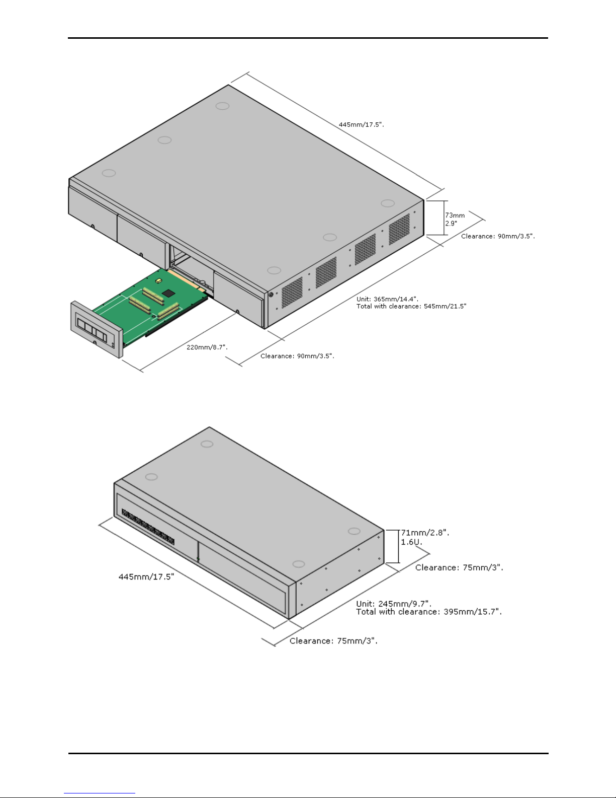
Deploying Avaya IP Office™ Platform IP500 V2 Page 54
15-601042 Issue 30j (18 May 2015)IP Office™ Platform 9.1
Comments on this document? [email protected]
2.2.1 IP500 V2 Control Units
The ventilation slots on the rear and sides should not be covered or blocked.
2.2.2 External Expansion Modules
The dimensions below are applicable to all IP Office external expansion modules.
Page 55
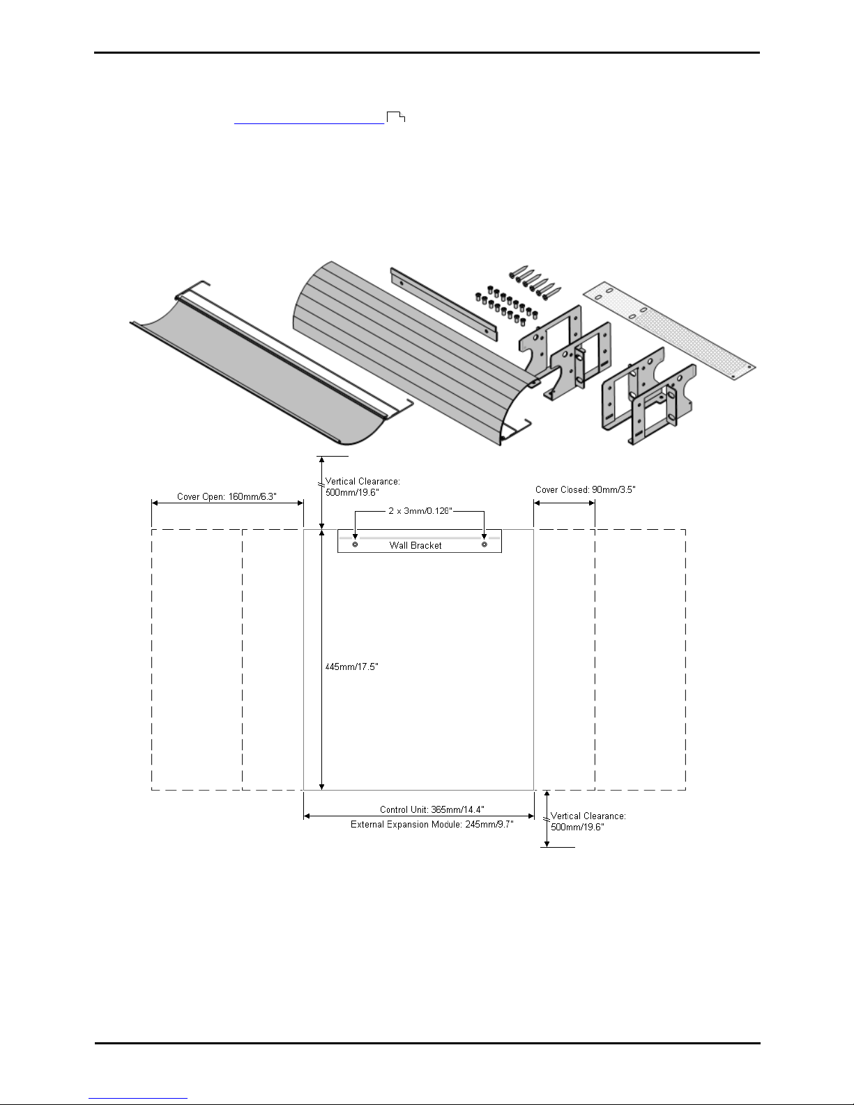
Deploying Avaya IP Office™ Platform IP500 V2 Page 55
15-601042 Issue 30j (18 May 2015)IP Office™ Platform 9.1
Comments on this document? [email protected]
Installation Requirements: Space Requirements
2.2.3 Wall Mounting
IP500 V2 control units and IP500 external expansion modules can be wall or rack mounted. To do this, a wall mounting
kit is required in addition to suitable wall fixings.
In addition to the existing environmental requirements for an IP Office system, the following additional requirements
apply when wall mounting a unit:
· The wall surface must be vertical, flat and vibration free. Attachment to temporary walls is not supported.
· Only the screws provided with the mounting kit should used to attach the brackets to the control unit.
The following wall and rack mounting kit is currently available:
· IPO IP500 RACK MNTG KIT V3 (SAP Code 700503160)
These kits can be used for wall and rack mounting of an IP500 V2 control unit and IP500 external expansion
modules. The kits incorporates cable routing at the front and rear of the unit. For wall mounted control units it
allows orientation of the control unit base card slots to the left or to the right.
52
Page 56
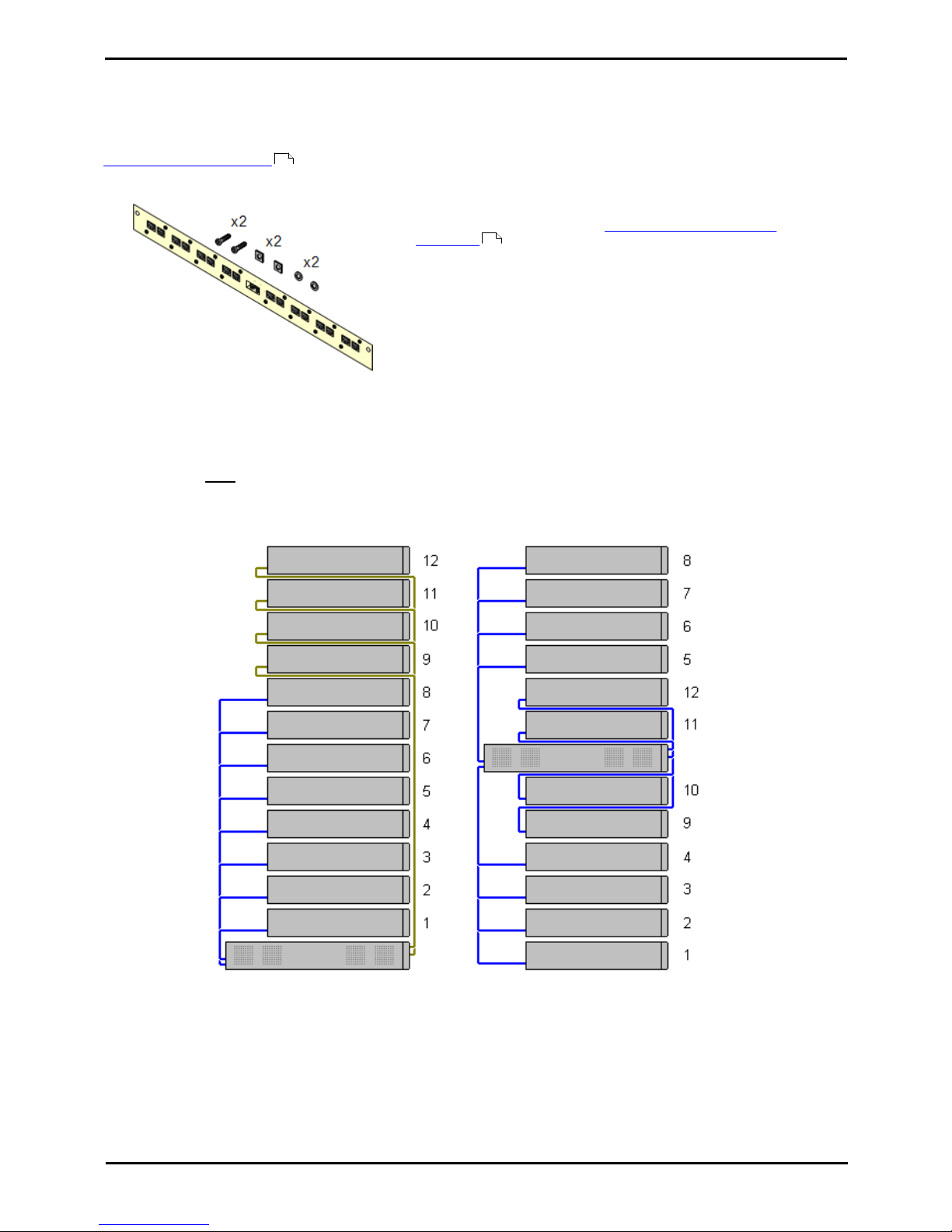
Deploying Avaya IP Office™ Platform IP500 V2 Page 56
15-601042 Issue 30j (18 May 2015)IP Office™ Platform 9.1
Comments on this document? [email protected]
2.2.4 Rack Space Requirements
All IP Office control units and external expansion modules can be rack mounted into standard 19" rack systems. Each unit
requires a 2U slot space within the rack. The IPO IP500 RACK MNTG KIT V3 is used for rack mounting of units.
Where IP Office systems are being rack mounted, the effect of conditions within the rack cabinet must be considered. For
example the rack temperature may be above the room temperature and airflow within the rack will be restricted. The
environmental requirements for the individual IP Office units are still applicable inside the rack cabinet.
Barrier Box Rack Mounting Kit
· Barrier Box Rack Mounting Kit (SAP 700293905)
Barrier boxes must be used for out-of-building analog phone
extensions . This bracket allows up to 8 IP Office barrier boxes to
be rack mounted and simplifies the number of connections to the
protective ground point in the rack. This kit must be used when more
than 3 barrier boxes are in use and supports a maximum of 16
barrier boxes for a single external expansion module.
Rack Module Positioning
The integral expansion ports on a control unit are located on the rear of the unit. For IP500 V2 control units, an additional
4 expansion ports can be added to the front of the control unit by installing an IP500 4-Port Expansion card.
· Each external expansion module is supplied with a blue 1 meter (3'3'') expansion interconnect cable. This
cable must be used when connecting to expansion ports on the rear of a control unit.
· When connecting to expansion ports on an IP500 4-Port Expansion card, a yellow 2 meter (6'6") expansion
interconnect cable can be used in place of the standard blue cable. 4 Yellow cables are supplied with the IP500
4-Port Expansion card.
52
36
Page 57

Deploying Avaya IP Office™ Platform IP500 V2 Page 57
15-601042 Issue 30j (18 May 2015)IP Office™ Platform 9.1
Comments on this document? [email protected]
IP500 V2 Installation
Overview
Chapter 3.
Page 58

Deploying Avaya IP Office™ Platform IP500 V2 Page 58
15-601042 Issue 30j (18 May 2015)IP Office™ Platform 9.1
Comments on this document? [email protected]
3. IP500 V2 Installation Overview
This installation process is a simple outline as installation requirements and processes will vary.
Installation process summary
1.Prepare for installation
a. Tools and Parts Required
Check that you have the tools and additional parts required.
b. Documentation
Ensure that you have obtained and read all the relevant documentation.
c. Unpacking
Check that all the required equipment has been delivered and that there is no damage.
2.Admin Software Installation
a. Installing the admin applications
IP Office Manager is an essential application for installation. This must be a copy of IP Office Manager that
matches the IP Office software level required.
b. Installer PC connection
Understand how IP Office Manager connects to a system and receives a copy of the configuration to edit.
3.Preparing the System SD card
a. Upgrade the SD card
Upgrade the System SD card to the latest release of IP Office software.
· ! WARNING: Installing PCS14 and earlier control units
PCS 14 or lower units must first install Release 8.1(65) (or higher 8.1) or any Release 9.0 and then
upgrade to Release 9.1. Care should be taken to ensure that no calls are made before the upgrade to
Release 9.1, otherwise the system will require an 9.1 upgrade license despite being "new". The PCS of
the control unit is printed on the label on the back of the control unit.
b. Pre-configuration options
The following options steps can be added to speed up installation and configuration: Create and load an offline
configuration file , Add a licenses file , Adding security certificates , Add a phone screen saver file
, Add music on hold files
4.Install the control unit cards
Attach any trunk daughter cards to the IP500 base cards. Insert the cards into the control unit.
a. Fit any IP500 trunk daughter cards to the IP500 base cards
b. Insert the IP500 base cards
5.Install the system
a. Wall Mounting
If wall mounting, attach the brackets and fit the unit to the wall.
b. Rack Mounting
If rack mounting, attach the brackets and fit the control unit into the rack.
c. Connect the External Expansion Modules
Connect the external expansions modules to the control unit.
d. Ground the system
Attach required ground cables to the control unit and external expansion modules.
e. LAN Network Connections
Attach the IP Office control unit and a PC with IP Office Manager to the LAN network.
f. Starting the System
Insert the System SD card and power up the system.
g. Connecting Phones
Connect the Avaya digital phones.
6.Initial configuration
7.Securing the system
59
60
61
65
67
72
74 75 75 76
76
78
79
80
82
82
84
85
87
88
89
92
96
112
Page 59

Deploying Avaya IP Office™ Platform IP500 V2 Page 59
15-601042 Issue 30j (18 May 2015)IP Office™ Platform 9.1
Comments on this document? [email protected]
IP500 V2 Installation Overview:
3.1 Tools and Equipment Required
The following is a general summary of the tools required. Additional tools and equipment will be
required for wall and or rack mounting and to fashion ground cable connections suitable to local
requirements.
· Tools Required
· o 5mm Flat-blade screwdriver.
· o Crosshead screwdriver.
· o Anti-static wrist strap and ground point.
· o RJ45-RJ45 Ethernet LAN Cable.
· o M4 Cross-Head Screwdriver.
· o Tools suitable for crimping a cable spade.
· o If wall mounting, drills and tools for wall mounting fixtures.
· Additional Parts Required
In addition to orderable IP Office equipment, the following items will be required.
· o 14AWG Solid copper wire for ground connection of control units and expansion modules.
· o Cable sleeve matching local regulator requirements for ground wires. Typically green for a functional
ground and green/yellow for a protective ground.
· o If wall mounting, additional fixtures and fittings suitable for the wall type and mounting kit being used.
· o Cable ties and labels for tidying and identifying cables.
· System Administration
1.o Selected method for system administration:
· Windows PC with IP Office Admin suite installed and RJ45 Ethernet LAN port.
2.o SD Card reader.
65
Page 60

Deploying Avaya IP Office™ Platform IP500 V2 Page 60
15-601042 Issue 30j (18 May 2015)IP Office™ Platform 9.1
Comments on this document? [email protected]
3.2 Documentation
Ensure that you have read this manual in full before starting installation. Also include the
installation documentation for any other equipment and applications being installed as
part of the IP Office system.
· ! IP Office Technical Bulletins
Ensure that you have obtained and read the IP Office Technical Bulletin relating to the IP Office software release
which you are installing. This bulletin will contain important information that may not have been included in this
manual. IP Office Technical Bulletins are available from the Avaya support website (http://support.avaya.com).
· ! Upgrade Licenses
Some upgrades may require entry of upgrade licenses. It is still possible to upgrade the system without the
necessary licenses, however the system will not provide any telephony functions after the upgrade until the
appropriate license is added to the system configuration.
· Avaya IP Office Platform Security Guidelines
· one-X Portal for IP Office Installation.
· Avaya H323 IP Phone Installation.
· Embedded Voicemail Installation.
· Voicemail Pro Installation.
· Contact Store Installation.
· Compact DECT Installation.
· IP DECT R4 Installation.
· 3600 Series Wireless IP Installation.
· SoftConsole Installation Manual.
· SIP Extension Configuration.
· 1100/1200 Series Phone Installation.
Information Web Sites
IP Office documentation is available from the following web sites.
· Avaya Support (http://support.avaya.com)
Contains documentation and other support materials for Avaya products including IP Office. Copies of the IP Office
CD images are available from this site and updated core software .bin files.
· Avaya IP Office Knowledge Base (http://marketingtools.avaya.com/knowledgebase)
Access to an on-line regularly updated version of the IP Office Knowledge Base.
Page 61

Deploying Avaya IP Office™ Platform IP500 V2 Page 61
15-601042 Issue 30j (18 May 2015)IP Office™ Platform 9.1
Comments on this document? [email protected]
IP500 V2 Installation Overview: Documentation
3.3 Unpacking
Use the following procedure when unpacking any equipment supplied by
Avaya or an Avaya reseller or distributor.
Information Required
· o Equipment Checklist.
An installation checklist of the parts and equipment ordered for the
installation.
Procedure
1.o Check for Packaging Damage
Before unpacking any equipment, check for any signs of damage that may have occurred during transit. If any
damage exists bring it to the attention of the carrier.
2.o Check the Correct Parts Have Been Delivered
Check all cartons against the packing slip and ensure that you have the correct items. Report any errors or
omissions to the equipment supplier.
3.o Retain All Packaging and Documentation
While unpacking the equipment, retain all the packaging material. Fault returns are accepted only if repackaged in
the original packaging. If performing a staged installation, the original packaging will also assist when repacking
equipment to be moved to the final install site.
4.o Ensure that Anti-Static Protection Measures are Observed
Ensure that anti-static protection measures are observed at all times when handling equipment with exposed
electrical circuit boards.
5.o Check All Parts
Visually inspect each item and check that all the necessary documentation and accessory items have been
included. Report any errors or omissions to the dealer who supplied the equipment.
6.o Check All Documentation
Ensure that you read and retain any documentation included with the equipment.
Page 62

Page 63

Deploying Avaya IP Office™ Platform IP500 V2 Page 63
15-601042 Issue 30j (18 May 2015)IP Office™ Platform 9.1
Comments on this document? [email protected]
Installing the Admin Software
Chapter 4.
Page 64

Deploying Avaya IP Office™ Platform IP500 V2 Page 64
15-601042 Issue 30j (18 May 2015)IP Office™ Platform 9.1
Comments on this document? [email protected]
4. Installing the Admin Software
In order to install and maintain an IP Office system you must be familiar with using the following applications.
· IP Office Manager
This is a Windows based application. IP Office Manager is used to access all parts of the IP Office configuration.
Different levels of access can be defined to control which parts of the configuration the user can view and alter. IP
Office Manager is also used to upgrade the software files used by an IP Office system.
· IP Office Web Manager
The configuration for an IP500 V2 system can be accessed via web browser using the same service user accounts
as used for IP Office Manager. Currently, for IP Office standard mode systems, IP Office Web Manager can only be
used to configure groups, users and service users (security accounts) and to perform basic maintenance actions.
Therefore, IP Office Manager is still required for full system installation and maintenance.
· System Status Application
The System Status Application (SSA) is a reporting tool that provides a wide range of information about the
current status of an IP Office system. Its can report the available resources and components within the system
and details of calls in progress. Details of the number of alarms are recorded and the time date of the most recent
alarms. When required for diagnostics escalation, SSA is able to take a snap shot image of the IP Office system's
status including a copy of its current configuration. Use of SSA requires an IP Office service user name and
password that has been configured for System Status access in the IP Office's security settings.
· Monitor (System Monitor)
System Monitor is a tool that can show all activity on the IP Office system in great detail. As a consequence,
interpretation of Monitor traces requires a high-level of data and telephony protocol knowledge. However, all IP
Office installers and maintainers must understand how to run Monitor when necessary as Avaya may request
copies of Monitor traces to resolve support issues.
4.1 IP Office Web Manager
Web browser access to the system can be used to run IP Office Web Manager. Enter the system's IP address and then
select the IP Office Web Management link.
For system's running in IP Office standard mode, IP Office Web Manager is currently used only for maintenance actions
(shutdown, reboot, upgrade, etc) and configuration of users and hunt groups. For full details, refer to the IP Office Web
Manager Manual. It does not allow access to the minimum configuration settings expected for initial system installation
and so it not covered in this document.
Page 65

Deploying Avaya IP Office™ Platform IP500 V2 Page 65
15-601042 Issue 30j (18 May 2015)IP Office™ Platform 9.1
Comments on this document? [email protected]
Installing the Admin Software: IP Office Web Manager
4.2 Installing the Admin Applications
The IP Office Administration suite consists of a number of applications for IP Office installers and
maintainers.
· o System Monitor - Install
· o Manager - Install
· o System Status Application - Install
· o Call Status - Optional
This software is not supported with IP Office Release 7.0 and higher systems. It is
provided only for the maintenance of older systems.
Requirements
· o IP Office Release 9.1 User/Admin DVD Set (2) (700506051)
Alternatively the IP Office Administrator Applications suite can be downloaded from Avaya's support website (
http://support.avaya.com).
· o Windows PC Requirements
This should meet the requirements of the administrator applications being installed. The specification below are
the minimum requirements for IP Office Manager. If other applications are to be installed on the PC then their
individual requirements should also be meet.
· Standard Manager: Core i3 CPU, 4GB RAM, 32/64 bit OS
· Server Edition Manager: Core i5 CPU, 6GB RAM , 32/64 bit OS
· Server Edition Select Manager: Core i5 CPU, 8GB RAM, 64 bit OS
Page 66
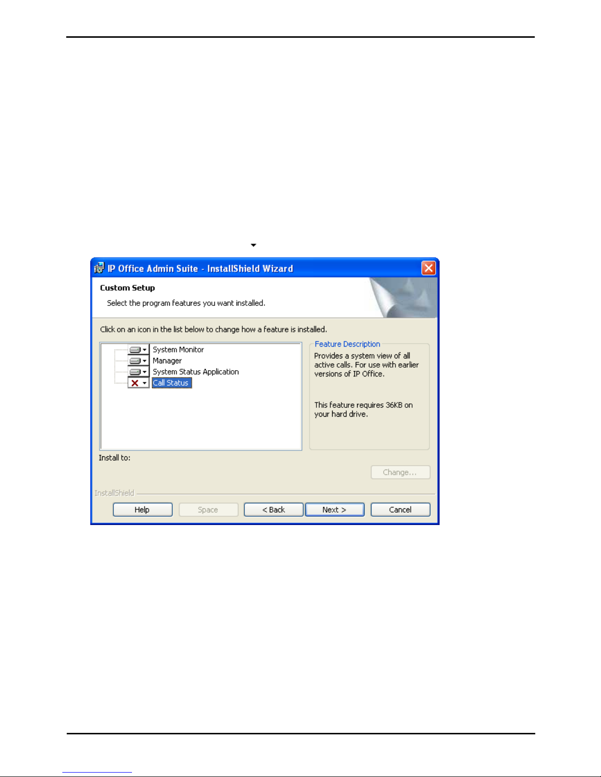
Deploying Avaya IP Office™ Platform IP500 V2 Page 66
15-601042 Issue 30j (18 May 2015)IP Office™ Platform 9.1
Comments on this document? [email protected]
To install the IP Office administrator applications:
1.Using the Add or Remove Programs option in the Windows Control Panel, check that the PC does not already
have a version of the IP Office Admin suite installed.
· If 'yes' and the suite is a pre-IP Office 3.2 version, remove the existing IP Office Admin suite via Add/Remove
Programs.
· If the existing suite is IP Office 3.2 or higher, it is possible to upgrade without removing the previous
installation.
2.Insert the IP Office Administrator Applications DVD. Select the option for the IP Office Administration Suit. A folder
window will display the installation files for the administration suite.
3.For Windows 7, right-click on setup.exe and select Run as administrator. Otherwise, double-click on setup.exe.
4.Select the language you want to use for the installation process. This does not affect the language used by IP
Office Manager when running. Click Next >.
5.Select who should be able to run the Admin Suite applications. Click Next >.
6.If required select the destination to which the applications should be installed. We recommend that you accept the
default destination. Click Next >.
7.The next screen is used to select which applications in the suite should be installed. Clicking on each will display a
description of the application. Click on the next to each application to change the installation selection. When
you have selected the installations required, click Next >.
8.Ensure that at minimum System Monitor and Manager are selected. Click Next >.
9.Click Install.
10.Installation of Windows .Net2 components may be required. If dialogs for this appear, follow the prompts to
install .Net.
11.If requested, reboot the PC.
Page 67
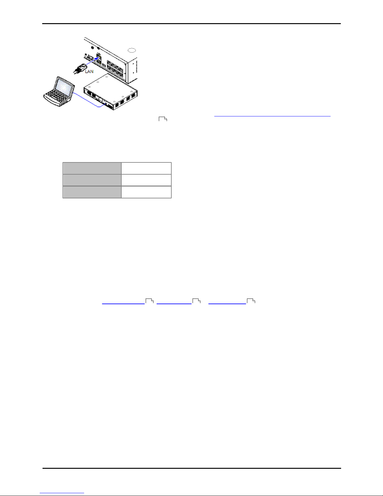
Deploying Avaya IP Office™ Platform IP500 V2 Page 67
15-601042 Issue 30j (18 May 2015)IP Office™ Platform 9.1
Comments on this document? [email protected]
Installing the Admin Software: Installing the Admin Applications
4.3 Installer PC Connection
During installation it is recommended that the IP Office control unit is started
without it being connected to any network. That ensures that the IP Office
defaults to a known set of IP address settings.
If the IP Office is started connected to a network with a DHCP server, the
programming PC will need to be connected to the same network as either a
DHCP client or with an IP address valid for that network.
This section covers connecting your installation PC directly to the IP Office
control unit.
Requirements
· o IP Office Administration PC
A Windows PC with the IP Office Administrator Application suite installed
.
· o LAN Cable
To connect directly to a defaulted IP Office system:
1.The default address for an IP Office control unit LAN port is 192.168.42.1/255.255.255.0. To directly connect a PC,
change the TCP/IP properties for the PCs LAN port to the following:
Fixed IP address
192.168.42.203
Subnet mask
255.255.255.0
Default gateway
192.168.42.1.
· While setting the PC to be a DHCP client could be used, this is not recommended for performing more
advanced functions such as firmware upgrades.
2.Connect the LAN cable from the PCs LAN port the LAN or LAN1 port on the IP Office control unit.
3.Check that the orange LED lamp on the IP Office LAN port is on. The green LED may also be flickering as it
indicates traffic across the LAN connection.
4.To test the connection before running IP Office Manager or System Status Application:
· Select Start | Run and enter cmd.
· In the command window that appears enter ping 192.168.42.1. The results should show a number of ping
replies from the IP Office. This confirms basic communication between the IP Office Manager PC and the IP
Office.
· If there are no ping replies enter ipconfig. The results should list the IP address settings of the IP Office
Manager PC as required above. If they do enter exit and check the cable connection.
5.You can now start IP Office Manager , System Status or System Monitor .
65
68 69 70
Page 68
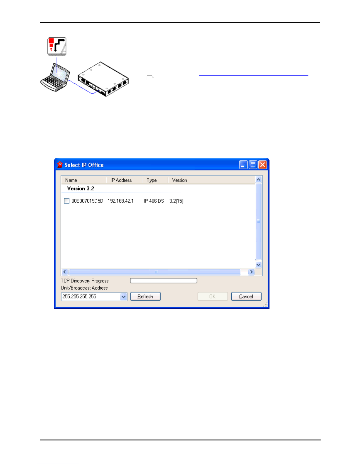
Deploying Avaya IP Office™ Platform IP500 V2 Page 68
15-601042 Issue 30j (18 May 2015)IP Office™ Platform 9.1
Comments on this document? [email protected]
4.4 Starting IP Office Manager
IP Office Manager is used to access all parts of the IP Office configuration. IP
Office Manager can also be used to upgrade the software files used by an IP
Office system.
Requirements
· o IP Office Administration PC
A Windows PC with the IP Office Administrator Application suite installed
.
· o LAN Cable
To start IP Office Manager:
1.Select Start | Programs | IP Office | Manager.
2.If the PC has firewall software installed, you may be prompted as to whether you want to allow this program to
access the network. Select Yes or OK.
3.Select File | Open Configuration from the menu bar.
4.The Select IP Office window appears. After a few seconds it should list the IP Office control unit. The default
display name used for a newly installed IP Office control unit is its MAC address.
· If the system required was not found, the address used for the search can be changed. Enter or select the
required address in the Unit/Broadcast Address field and then click Refresh to perform a new search.
5.Click the check the box next to the system and then click OK.
6.The name and password request is displayed. The name and password must match one of those setup through the
security settings. The default name and password for configuration access are Administrator and Administrator
.
65
Page 69
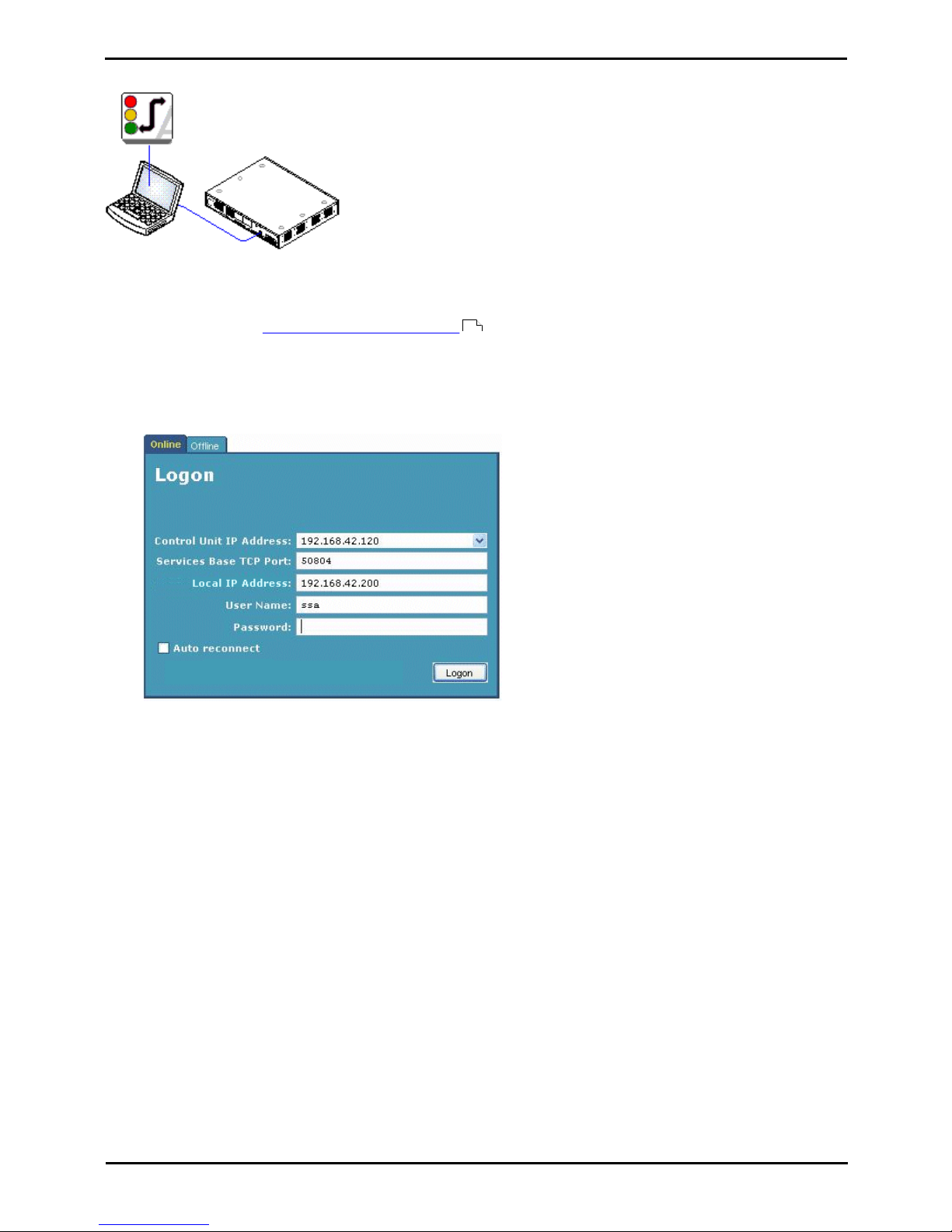
Deploying Avaya IP Office™ Platform IP500 V2 Page 69
15-601042 Issue 30j (18 May 2015)IP Office™ Platform 9.1
Comments on this document? [email protected]
Installing the Admin Software: Starting IP Office Manager
4.5 Starting System Status Application
The System Status Application (SSA) is a reporting tool that provides a wide
range of information about the current status of an IP Office system. Its can
report the available resources and components within the system and details of
calls in progress. Details of the number of alarms are recorded and the time date
of the most recent alarms.
When required for diagnostics escalation, SSA is able to take a snap shot image
of the IP Office system's status including a copy of its current configuration. Use
of SSA requires an IP Office service user name and password that has been
configured for System Status access in the IP Office's security settings.
To start System Status:
1.There are several methods that can be used to start the System Status Application.
· On a PC where System Status has been installed , select Start | Programs | IP Office | System Status
.
· If IP Office Manager is also installed on the PC and is running, select File | Advanced | System Status.
· For IP500 V2 controls units, start a web browser and enter the IP address of the control unit. Select the link
for the System Status.
2.Once System Status has started, it will request the details of the IP Office system to which you want it to connect.
· Control Unit IP Address
Enter the IP address of the IP Office control units LAN interface or use the drop down to select a previously
used address.
· Services Base TCP Port
This should match the Services Base TCP Port setting of the IP Office system, set in that systems security
settings. The default is 50804.
· Local IP Address
If the PC has more than one IP address assigned to its network card or multiple network cards, the address to
use can be selected if necessary.
· User Name/Password
Enter a user name and password that has been provided for System Status usage. By default this is the same
as the user name and password used with IP Office Manager. This must be the name of an IP Office service
user name that has been configured for system status access in the IP Office's security settings.
· Auto Reconnect
If selected, System Status will attempt to reconnect using the same settings if connection to the IP Office is
lost.
3.Enter the required details for the IP Office and click Logon.
65
Page 70
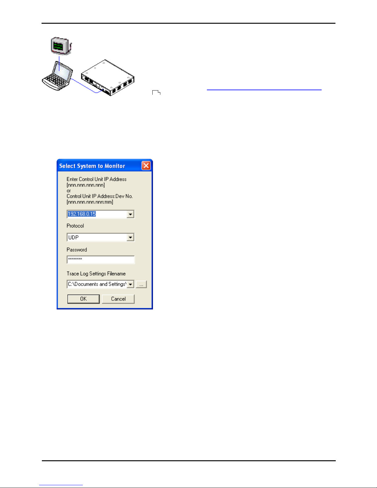
Deploying Avaya IP Office™ Platform IP500 V2 Page 70
15-601042 Issue 30j (18 May 2015)IP Office™ Platform 9.1
Comments on this document? [email protected]
4.6 Starting System Monitor
System Monitor is a tool that can show all activity on the IP Office system in
great detail. As a consequence, interpretation of Monitor traces requires a highlevel of data and telephony protocol knowledge. However, all IP Office installers
and maintainers must understand how to run Monitor when necessary as Avaya
may request copies of Monitor traces to resolve support issues.
Requirements
· o IP Office Administration PC
A Windows PC with the IP Office Administrator Application suite installed
.
· o LAN Cable
1.To start System Monitor:
1.Select Start | Programs | IP Office | System Monitor.
2.If System Monitor has run before, it automatically attempts to connect with the system that was previously being
monitored. If otherwise or you want to monitor a different system, use the steps below to select the required
system.
3.Select File and then Select Unit.
4.Enter the IP Address and Password of the system that you want to monitor.
· Protocol
The default Protocol for System Monitor operation is UDP. This reduces the impact on the system of sending
records, especially when a large number of records are being sent. The TCP is only supported when
connecting to system running the IP Office Release 9.0 or higher. Using the TCP protocol to connect to pre-9.0
systems can cause packet congestion on the IP Office and affect services. In order to use System Monitor
remotely through Avaya SAL, select TCP.
· Which Password?
Using IP Office Manager, it is possible to set a specific Monitor Password. If the system does not have a
Monitor Password set, System Monitor uses the system's System Password. The Monitor Password and
System Password are set within a system's security configuration settings.
5.If you want System Monitor to start with a previously saved set of trace options, use the Trace Log Settings
Filename browse button to select the trace options settings file.
6.Click OK.
65
Page 71

Deploying Avaya IP Office™ Platform IP500 V2 Page 71
15-601042 Issue 30j (18 May 2015)IP Office™ Platform 9.1
Comments on this document? [email protected]
Preparing the System SD
Card
Chapter 5.
Page 72

Deploying Avaya IP Office™ Platform IP500 V2 Page 72
15-601042 Issue 30j (18 May 2015)IP Office™ Platform 9.1
Comments on this document? [email protected]
5. Preparing the System SD Card
New IP500 V2 control units are supplied with no installed firmware or configuration. When first powered up, the control
unit loads and installs the necessary firmware from the System SD card installed in the control unit. It then creates a
default configuration matching the physical cards already installed in the control unit and any external expansion modules
already attached to it.
· ! WARNING: Installing PCS14 and earlier control units
PCS 14 or lower units must first install Release 8.1(65) (or higher 8.1) or any Release 9.0 and then
upgrade to Release 9.1. Care should be taken to ensure that no calls are made before the upgrade to
Release 9.1, otherwise the system will require an 9.1 upgrade license despite being "new". The PCS of
the control unit is printed on the label on the back of the control unit.
You can perform a number of additional actions prior to installing the System SD card in order to pre-configure the
system. These can greatly speed up the physical installation at the customer site as they can all be done in advance.
· Upgrade the Card Firmware
· Add a Configuration File
· Add a License File
· Adding Security Certificates
· Add a 9600 Screen Saver Image File
· Add Music on Hold Files
Additional actions that can be performed on SD cards are detailed in the SD Card Management section.
73
75
75
75
76
76
120
Page 73
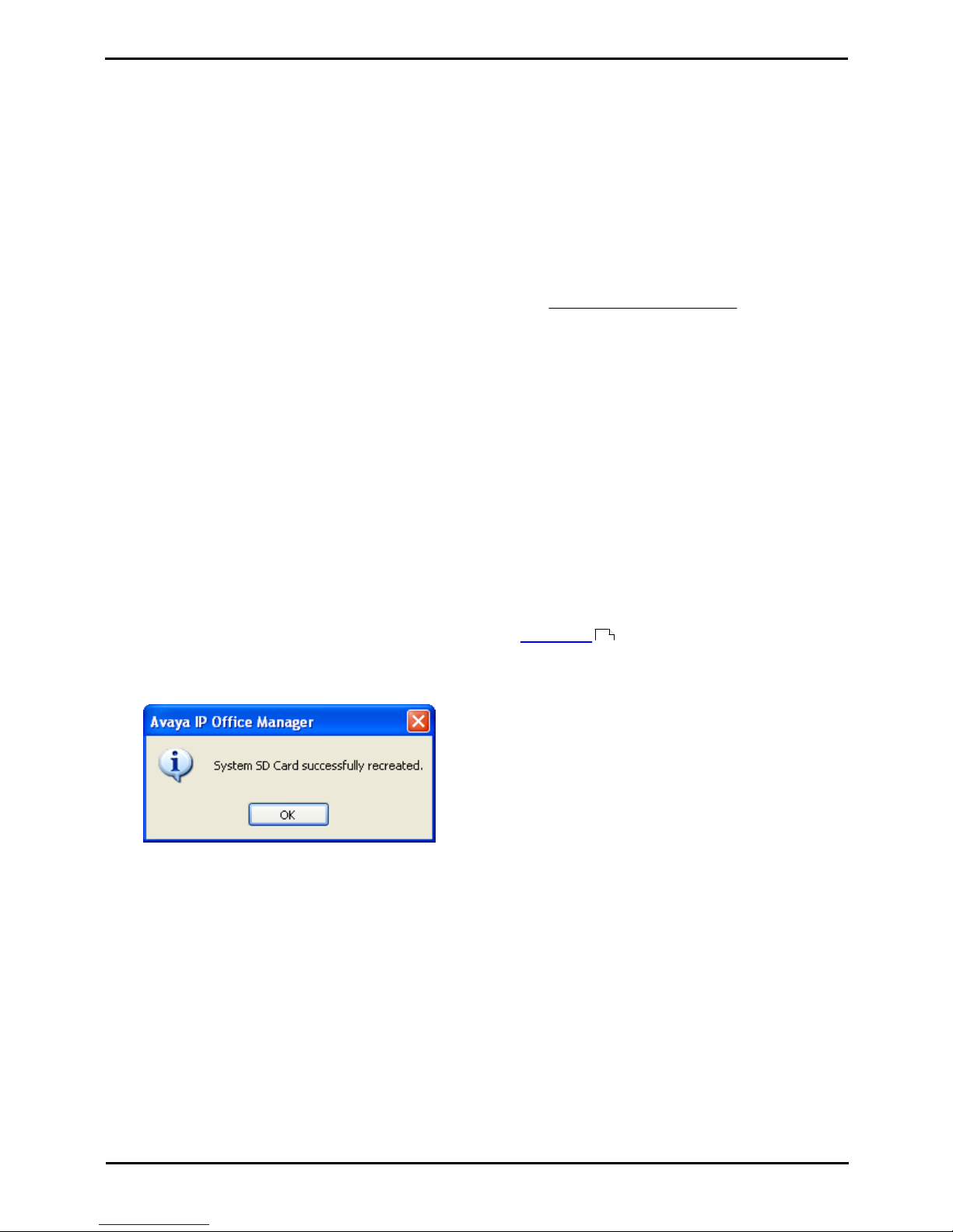
Deploying Avaya IP Office™ Platform IP500 V2 Page 73
15-601042 Issue 30j (18 May 2015)IP Office™ Platform 9.1
Comments on this document? [email protected]
Preparing the System SD Card:
5.1 Upgrade the Card Firmware
This command can be used with a read-writeable SD card on the IP Office Manager PC. It copies the files and folders
used by an IP500 V2 system when starting. It updates the card with the version of those files installed with the IP Office
Manager application. It includes the binary files for the IP500 V2 system, external expansion modules and phones. It also
includes the prompt files for Embedded Voicemail operation.
· ! WARNING: Installing PCS14 and earlier control units
PCS 14 or lower units must first install Release 8.1(65) (or higher 8.1) or any Release 9.0 and then
upgrade to Release 9.1. Care should be taken to ensure that no calls are made before the upgrade to
Release 9.1, otherwise the system will require an 9.1 upgrade license despite being "new". The PCS of
the control unit is printed on the label on the back of the control unit.
This process replaces existing files and adds new files. It does not delete files, so for example, any existing Embedded
Voicemail messages and greetings are retained. If the card contains dynamic system files such as SMDR records, they
are temporarily backed up by IP Office Manager and then restored after the card is recreated.
For the card to be used in an IP500 V2 system's System SD slot the card must be Avaya System SD card. The card
must be correctly formatted, however a reformat of an existing working card is not necessary before using recreate to
update the card contents.
· The source for the files copied to the SD card are the sub-folders of the \Memory Cards folder under Manager's
applications Working Directory (normally C:\Program Files Avaya\IP Office\Manager). However, if the
Working Directory is changed to a location without an appropriate set of \Memory Cards sub-folders, the
required set of files will not be copied onto the SD card.
To upgrade a System SD card
1.Once started do not interrupt this process, for example by removing the SD card. This process takes
approximately 15 minutes.
2.Insert the SD card into a card reader on the IP Office Manager PC.
3.Using IP Office Manager, select File | Advanced | Recreate IP Office SD Card.
4.Select IP Office A-Law, IP Office U-Law, IP Office Partner Edition. or IP Office Norstar Edition. This
selection will affect how the IP Office systems operates when defaulted with this card present in its System SD
card slot.
5.Browse to the card location and click OK.
6.IP Office Manager will prompt whether you want to include Avaya IP Office Web Manager files as part of the
recreate process. Those files are necessary if you want to run IP Office Web Manager to manage the IP Office
system into which the card will be loaded or if you want to use on-boarding .
7.IP Office Manager will start creating folders on the SD card and copying the required files into those folders. This
process will take approximately 15 minutes.
8.Do not remove the SD card during the process. Wait until the IP Office Manager displays a message.
116
Page 74
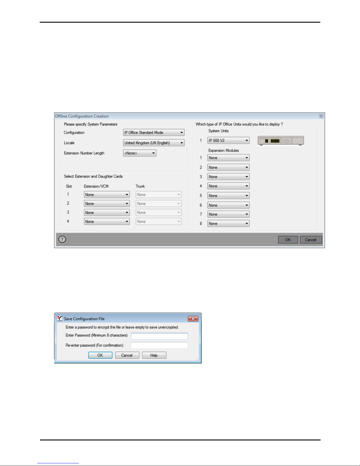
Deploying Avaya IP Office™ Platform IP500 V2 Page 74
15-601042 Issue 30j (18 May 2015)IP Office™ Platform 9.1
Comments on this document? [email protected]
5.2 Creating an Offline Configuration File
IP Office Manager can be used to create a new configuration without connecting to an IP Office system. During the
process, you can specify the locale of the system, what type of trunk cards it uses and what type of control unit and
expansion modules to include.
This allows the creation of a configuration prior to installation of system. The configuration file can be placed onto the
System SD card before it is installed into the system. Otherwise the configuration can be uploaded to the system after
initial installation of the system.
· The configuration created must match the physical equipment in the IP Office system onto which the configuration
will be loaded. Doing otherwise may cause the IP Office system to reset and experience other problems.
To create an offline configuration file
1.Start IP Office Manager with no configuration loaded into IP Office Manager
2.Select File | Create an Offline Configuration .
3.Select the type of configuration that you want to create. The equipment and settings are restricted to those
supported in the selected mode.
4.When completed click OK.
5.IP Office Manager creates and loads the configuration.
6.Edit the configuration to match the customer requirements. This can include importing information from
preprepared CSV files.
7.When completed, select File | Save Configuration As.
8.When prompted to enter a password to encrypt the file, leave the fields blank and click OK.
Page 75

Deploying Avaya IP Office™ Platform IP500 V2 Page 75
15-601042 Issue 30j (18 May 2015)IP Office™ Platform 9.1
Comments on this document? [email protected]
Preparing the System SD Card: Creating an Offline Configuration File
5.3 Adding a Pre-Built Configuration File
IP Office Manager can be used to create an offline configuration file . For IP500 V2 control units, such a pre-created IP
Office configuration file can be placed on the System SD card. That file is then loaded when the new IP Office system is
started.
To load a pre-built offline configuration onto a System SD card
1.Using IP Office, create an offline configuration that matches the customer requirements and the equipment that
will be installed in the IP Office.
2.Rename the configuration file config.cfg.
3.Using a card reader, copy the file into the /system/primary folder on the System SD memory card.
5.4 Adding a License File
For IP500 V2 control units, if a licence file called keys.txt is found in the SD card folder which the IP Office uses when it
boots, the IP Office will merge the licenses in that file with its configuration.
The files should be a plain text file (UTF8) containing either:
· A license name and license key separated by a
comma on each line.
Teleworker, uAuToY@9VvVV@VOzIgeegwLXL2sAs1Z5
Mobile Worker, NvWO_iVY5KJpZMNeY89IB1sIj0_QUCDm
Power User, 9IJQW3yuPsbxjGS2XcMa16_J9H8cSeZ9
System Advanced, JAWZaw@YtK37vcnXkqM4mDYDIdSMd9_1
· A license key on each line.
uAuToY@9VvVV@VOzIgeegwLXL2sAs1Z5
NvWO_iVY5KJpZMNeY89IB1sIj0_QUCDm
9IJQW3yuPsbxjGS2XcMa16_J9H8cSeZ9
JAWZaw@YtK37vcnXkqM4mDYDIdSMd9_1
To load a License File onto a system SD card
1.Using a card reader, copy the file into the /system/primary folder on the System SD memory card.
5.5 Adding Security Certificates
The IP Office system can use security certificates to validate and secure the connections between itself and application
and between other IP Office systems. Certificates can also be used for secure telephony communications.
Certificates can be placed onto the System SD card. Those certificates are then loaded into the system's certificate store
when the system is started. The certificate file name extension must indicate the type of encoding; PEM encoded files
should end with .pem, DER encoded files should end with .der.
To load a certificate to add:
1.Using a card reader, copy the file into the /system/primary/certificates/tcs/add folder on the System SD
memory card.
To load a certificate to remove:
The mechanism above can adapted to also remove an existing certificate.
1.Using a card reader, copy the file into the /system/primary/certificates/tcs/remove folder on the System SD
memory card. If the matching certificate already exists in the system certificate store, that certificate is removed.
74
Page 76
Deploying Avaya IP Office™ Platform IP500 V2 Page 76
15-601042 Issue 30j (18 May 2015)IP Office™ Platform 9.1
Comments on this document? [email protected]
5.6 Adding a 9600 Series Screen Saver File
When idle, 9600 Series phones can timeout to displaying a screen saver image. A file, 96xxiposs.jpg, is present on the
cards by default.
You can replace this file with your own branded file. The file should be smaller than the screen size on 9600 Series
phones in order to then be moved around the screen.
Phone
Maximum Size
Phone
Maximum Size
Phone
Maximum Size
9611
160x160
9621G
320x160
9650
320x240
9620
320x160
9630
320x240
9650C
320x240
9620L
320x160
9640
320x240
9620C
320x160
9641G
320x240
· Color Displays: Color depth is 16 bit. A separate color image will look best.
· Non-Color Displays: Best results are achieved with a single grayscale logo image. 2 levels of grayscale are also
supported.
· To invoke transparent backgrounds with logos, use a background color of 0,255,0 (brightest possible green).
5.7 Adding Music on Hold Files
By default the IP Office will use internal music on hold by uploading a music file from the IP Office Manager PC. For IP500
V2 systems, you can load a file onto the System SD card prior to installing it in the IP Office.
The file must be of the following format and must be called holdmusic.wav.
Property
Value
File Type
WAV
Bit Rate
128kbps
Audio sample size
16 bit
Channels
1 (mono)
Audio Sample Rate
8 kHz
Audio Format
PCM
Length
Up to 90 seconds.
To loading a music on hold file onto a System SD card
1.Rename the music file holdmusic.wav.
2.Using a card reader, copy the file into the /system/primary folder on the System SD memory card.
3.If the IP Office is or will be configured for additional hold music files (up to 3 additional files), copy those files to
the same location. The name of the additional files must match those specified in the IP Office system's
configuration.
Page 77

Deploying Avaya IP Office™ Platform IP500 V2 Page 77
15-601042 Issue 30j (18 May 2015)IP Office™ Platform 9.1
Comments on this document? [email protected]
Installing the Control Unit
Cards
Chapter 6.
Page 78
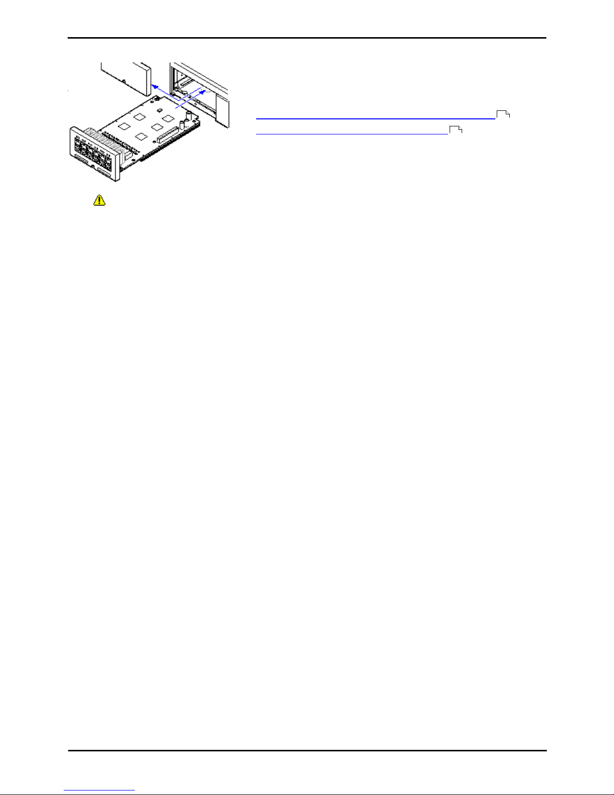
Deploying Avaya IP Office™ Platform IP500 V2 Page 78
15-601042 Issue 30j (18 May 2015)IP Office™ Platform 9.1
Comments on this document? [email protected]
6. Installing the Control Unit Cards
The IP500 base cards and trunk daughter cards should be fitted before power
is applied to the control unit. Ensure that cards are inserted in the order that
matches the planned or pre-built configuration.
This process has 2 stages:
1.Fit the IP500 trunk daughter cards onto the IP500 base cards.
2.Insert the IP500 Base Cards into the Control Unit.
· Warnings
· Correct anti-static protection steps should be taken before handling circuit boards.
· Cards must never be added or removed from the control unit while it has power connected.
· General Notes
· Cards can be fitted in any order into any available slots. The only exception is the IP500 4-Port Expansion
card which can only be installed in right hand slot 4.
79
80
Page 79
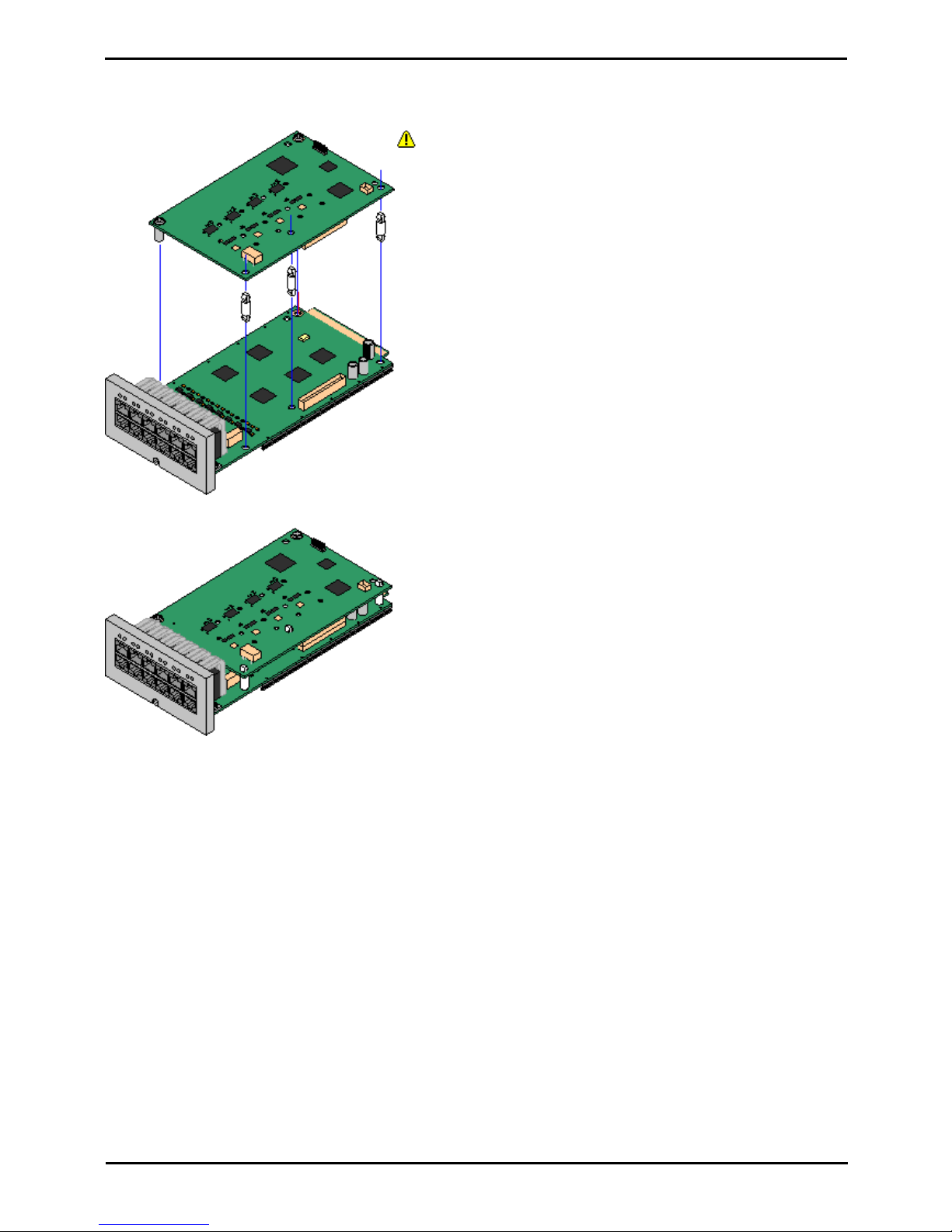
Deploying Avaya IP Office™ Platform IP500 V2 Page 79
15-601042 Issue 30j (18 May 2015)IP Office™ Platform 9.1
Comments on this document? [email protected]
Installing the Control Unit Cards:
6.1 Fitting IP500 Daughter Cards
IP500 trunk daughter cards can be fitted to any IP500 base card except the Unified Communications Module and 4-Port
Expansion card. For IP500 Combination cards, the trunk daughter card is pre-installed and cannot be changed.
Warnings
1.Correct anti-static protection steps should be taken while
handling circuit boards.
Parts and Equipment Required
1.o IP500 Base Card
2.o IP500 Trunk Daughter Card
3.o 3 Stand Off Pillars
These are supplied with the trunk daughter card.
Tools Required.
1.o 5mm Flat-blade screwdriver.
2.o Anti-static wrist strap and ground point.
Procedure: Installing a Trunk Daughter Card
1.Check that correct cards have been supplied.
2.Ensure that you are wearing an anti-static wrist strap connected
to a suitable ground point.
3.On the base card identify the position of 3 holes for the plastic
pillars for the IP500 card. These are along the same edge as the
card connector.
4.Fit the stand off pillars to the IP500 base card.
5.If there is a clip-on metal shield over the connector block on the
base card, remove it.
6.Using minimal force and checking that the pins are correctly
located, push the IP500 trunk card onto its connector block and
the stand off pillars.
7.Check that the card connector has snapped into position.
8.Using the washers and screws provided, secure the metal stand
off pillars to the base card.
9.A set of labels are supplied with the trunk daughter card. Fit the
appropriate label to the front of the base card.
Page 80
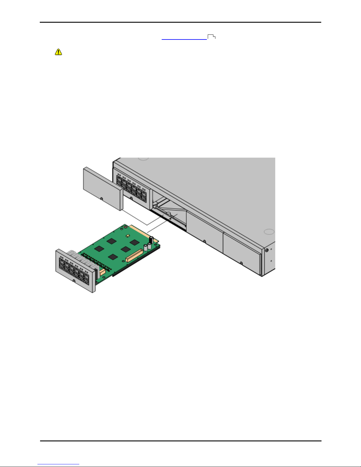
Deploying Avaya IP Office™ Platform IP500 V2 Page 80
15-601042 Issue 30j (18 May 2015)IP Office™ Platform 9.1
Comments on this document? [email protected]
6.2 Inserting IP500 Base Cards
Having prepared each IP500 base card by adding any trunk daughter card , the base card can be inserted into the
control unit.
· Warnings
· Correct anti-static protection steps should be taken while handling circuit boards.
· Cards must never be added or removed from the control unit while it has power connected.
· Tools Required
· o 5mm Flat-blade screwdriver.
· o Anti-static wrist strap and ground point.
Installing an IP500 Card
1.Check that there is no power to the control unit.
2.Using a flat-bladed screwdriver, remove the cover from the slot on the front of the control unit that will be used for
each card being installed. This cover is no longer required but should be retained until installation has been
completed.
3.Allowing the card to rest against the bottom of the slot, begin sliding it into the control unit. When half inserted,
check that the card rails have engaged with the slot edges by trying to gently rotate it. If the card rotates remove
it and begin inserting it again.
4.The card should slide in freely until almost fully inserted. At this point apply pressure at the base of the front of the
card to complete insertion.
5.Using a flat-bladed screwdriver secure the card.
79
Page 81

Deploying Avaya IP Office™ Platform IP500 V2 Page 81
15-601042 Issue 30j (18 May 2015)IP Office™ Platform 9.1
Comments on this document? [email protected]
Installing the Physical
System
Chapter 7.
Page 82
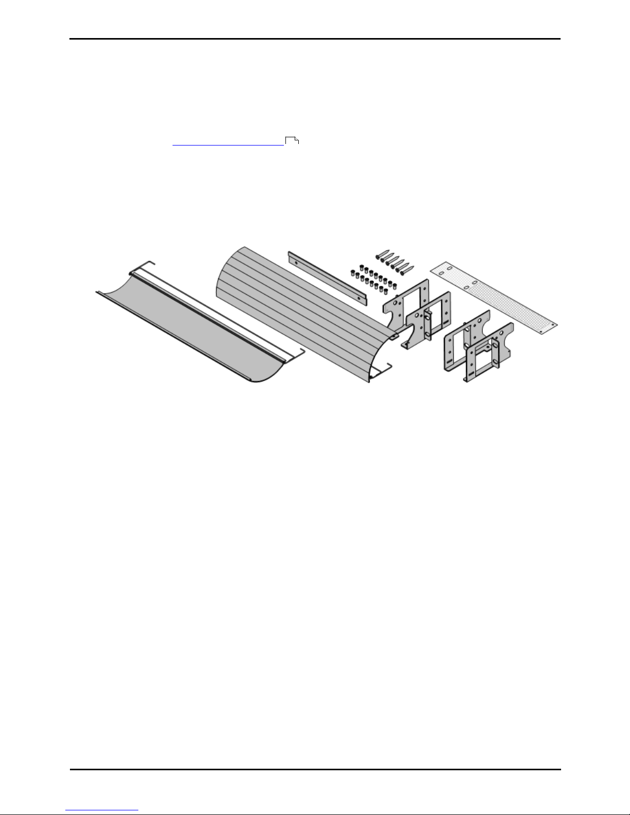
Deploying Avaya IP Office™ Platform IP500 V2 Page 82
15-601042 Issue 30j (18 May 2015)IP Office™ Platform 9.1
Comments on this document? [email protected]
7. Installing the Physical System
Having prepare for installation, this section covers the basic on-site installation.
7.1 Wall Mounting
IP500 V2 control units and IP500 external expansion modules can be wall or rack mounted. To do this, a wall mounting
kit is required in addition to suitable wall fixings.
In addition to the existing environmental requirements for an IP Office system, the following additional requirements
apply when wall mounting a unit:
· The wall surface must be vertical, flat and vibration free. Attachment to temporary walls is not supported.
· Only the screws provided with the mounting kit should used to attach the brackets to the control unit.
The following wall and rack mounting kit is currently available:
· IPO IP500 RACK MNTG KIT V3 (SAP Code 700503160)
These kits can be used for wall and rack mounting of an IP500 V2 control unit and IP500 external expansion
modules. The kits incorporates cable routing at the front and rear of the unit. For wall mounted control units it
allows orientation of the control unit base card slots to the left or to the right.
52
Page 83
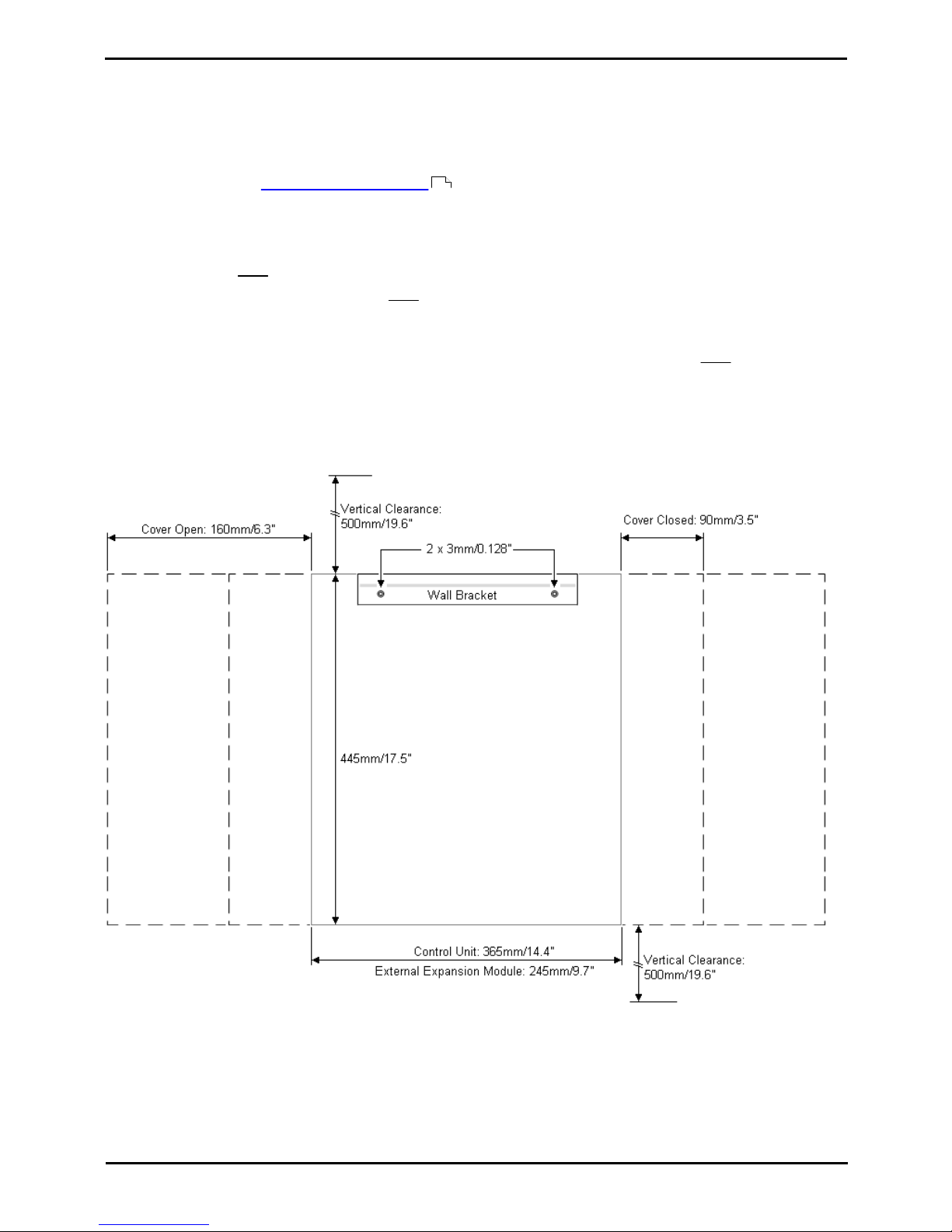
Deploying Avaya IP Office™ Platform IP500 V2 Page 83
15-601042 Issue 30j (18 May 2015)IP Office™ Platform 9.1
Comments on this document? [email protected]
Installing the Physical System: Wall Mounting
7.1.1 Wall Mounting Kit V2/V3
These notes relate to the IPO IP500 RACK MNTG KIT V2 (SAP 700500923) and IPO IP500 RACK MNTG KIT V3
(SAP 700503160). These kits can be used to wall or rack mount IP500 V2 control units and IP500 external expansion
modules.
The kits includes all components necessary for wall mounting onto a plywood surface. The use of the cable covers is
optional.
In addition to the existing environmental requirements for an IP Office system, the following additional requirements
apply when wall mounting a unit:
· The wall surface must be vertical, flat and vibration free. Attachment to temporary walls is not supported.
· Only the screws provided with the mounting kit should used to attach the brackets to the control unit.
· The installation must be done by a service person only.
· For control units, the mesh flame screen must be installed on the bottom edge of the control unit before
mounting.
· For the V3 kit, the flame screen attaches to the outside of the control unit.
· For the V2 kit, the flame screen is inserted inside the control unit chassis. To do this you must wait at least 15
minutes after removing the power cord before fitting the flame screen.
· Ensure that the system has been shutdown and power has been removed from all the units. Shutdown the system
using a shutdown command and then remove power. Do not simply remove the power.
· A suitable mounting surface of at least 19mm (0.75 inch) plywood is required.
· Full installation instructions are included with the kit.
52
Page 84
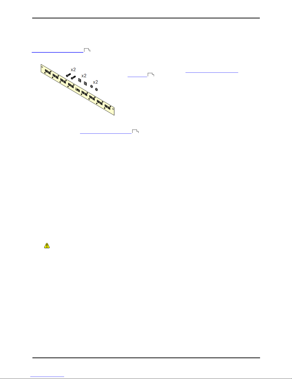
Deploying Avaya IP Office™ Platform IP500 V2 Page 84
15-601042 Issue 30j (18 May 2015)IP Office™ Platform 9.1
Comments on this document? [email protected]
7.2 Rack Mounting
All IP Office control units and external expansion modules can be rack mounted into standard 19" rack systems. Each unit
requires a 2U slot space within the rack. The IPO IP500 RACK MNTG KIT V3 is used for rack mounting of units.
Where IP Office systems are being rack mounted, the effect of conditions within the rack cabinet must be considered. For
example the rack temperature may be above the room temperature and airflow within the rack will be restricted. The
environmental requirements for the individual IP Office units are still applicable inside the rack cabinet.
Barrier Box Rack Mounting Kit
· Barrier Box Rack Mounting Kit (SAP 700293905)
Barrier boxes must be used for out-of-building analog phone
extensions . This bracket allows up to 8 IP Office barrier boxes to
be rack mounted and simplifies the number of connections to the
protective ground point in the rack. This kit must be used when more
than 3 barrier boxes are in use and supports a maximum of 16
barrier boxes for a single external expansion module.
Environmental Requirements
In addition to the existing environmental requirements for an IP Office system, the following additional factors must
be considered when rack mounting a unit:
1.Rack Positioning - Ensure compliance with the rack manufacturers safety instructions. For example check that the
rack legs have been lowered and fixing brackets have been used to stop toppling.
2.Elevated Operating Ambient - If installed in a closed or multi-unit rack assembly, the operating ambient
temperature of the rack environment may be greater than room ambient. Therefore, consideration should be given
to installing the equipment in an environment compatible with the maximum ambient temperature (Tma) specified
by the manufacturer.
· o Operating Temperature: 5°C (40°F) to 40°C (104°F).
· o Operating Humidity: 10% to 95% non-condensing.
3.Reduced Air Flow - Installation of the equipment in a rack should be such that the amount of air flow required for
safe operation of the equipment is not compromised. Proper ventilation must be maintained. The side ventilation
slots on the IP500 control unit should not be covered or blocked.
4.Mechanical Loading - Mounting of the equipment in the rack should be such that a hazardous condition is not
achieved due to uneven mechanical loading.
5.Circuit Overloading - Consideration should be given to the connection of the equipment to the supply circuit and
the effect that overloading of the circuits might have on overcurrent protection and supply wiring. Appropriate
consideration of equipment nameplate ratings should be used when addressing this concern.
6.Reliable Earthing - Reliable earthing of rack-mounted equipment should be maintained. Particular attention should
be given to supply connections other than direct connections to the branch circuit (e.g. use of power strips).
7. Only the screws provided with the mounting kit should used to attach the brackets to the control unit.
52
36
52
Page 85
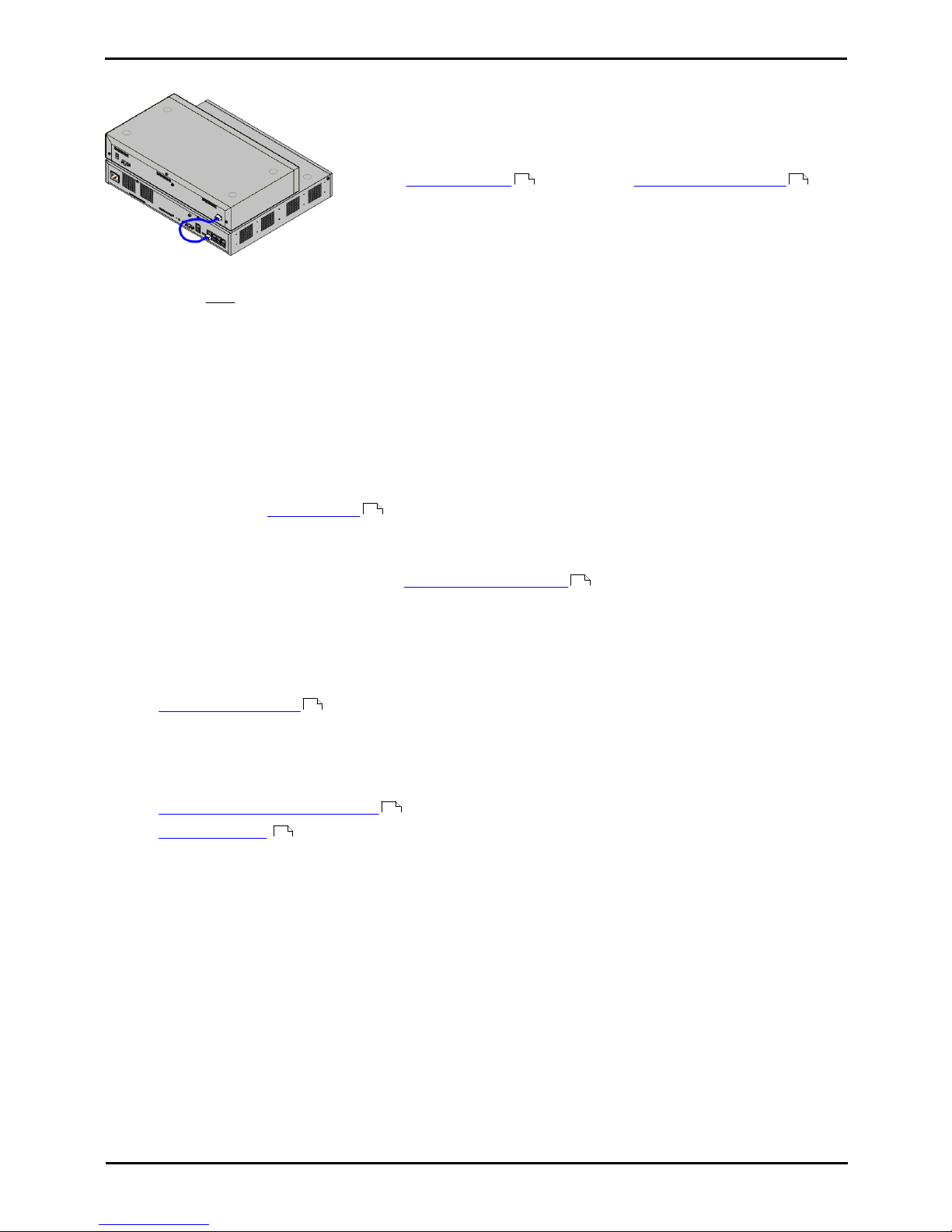
Deploying Avaya IP Office™ Platform IP500 V2 Page 85
15-601042 Issue 30j (18 May 2015)IP Office™ Platform 9.1
Comments on this document? [email protected]
Installing the Physical System: Rack Mounting
7.3 Connecting External Expansion Modules
Any external expansion modules should be connected to the control unit before
power is applied to the control unit. Ensure that modules are attached in the order
that matches the planned or pre-built configuration.
External expansion modules connect to the IP Office control unit using an
expansion interconnect cable. Each module is supplied with an expansion connect
cable and a power supply unit . An appropriate locale specific power cord
for the power supply unit must be ordered separately.
· Each external expansion module is supplied with a blue 1 meter (3'3'') expansion interconnect cable. This
cable must be used when connecting to expansion ports on the rear of a control unit.
· When connecting to expansion ports on an IP500 4-Port Expansion card, a yellow 2 meter (6'6") expansion
interconnect cable can be used in place of the standard blue cable. 4 Yellow cables are supplied with the IP500
4-Port Expansion card.
Installation Requirements
· o Installation space either on or under the existing IP Office control unit.
· o Switched power outlet socket.
· o Available EXPANSION port on the control unit.
· o Grounding Requirements
· o Functional Grounding
Connection of a functional earth is:
· o Recommend for all modules.
· o Connection of a functional ground is mandatory for Analog Trunk modules.
· o Protective Grounding
Connections of a protective ground via surge protection equipment is:
· o Mandatory for Analog trunk modules in the Republic of South Africa.
· o Mandatory for Digital Station and Phone modules connected to out of building extensions.
· o Mandatory for Digital Station V2 and Phone V2 modules.
Tools Required
· o IP Office Manager PC.
· o Tools for rack mounting (optional).
Parts and Equipment Required
· o External Expansion Module.
Each module is supplied with a suitable external power supply unit and a 1m blue interconnect cable. 2m Yellow
interconnect cables are supplied with the IP500 4-Port Expansion card and should only be used with that card.
· o Power cord for the power supply unit .
· o Rack mounting kit (optional).
· o Wall mounting kit - IP500 external expansion modules only (optional).
· o Cable labeling tags.
30 31
35
36
84
31
37
Page 86
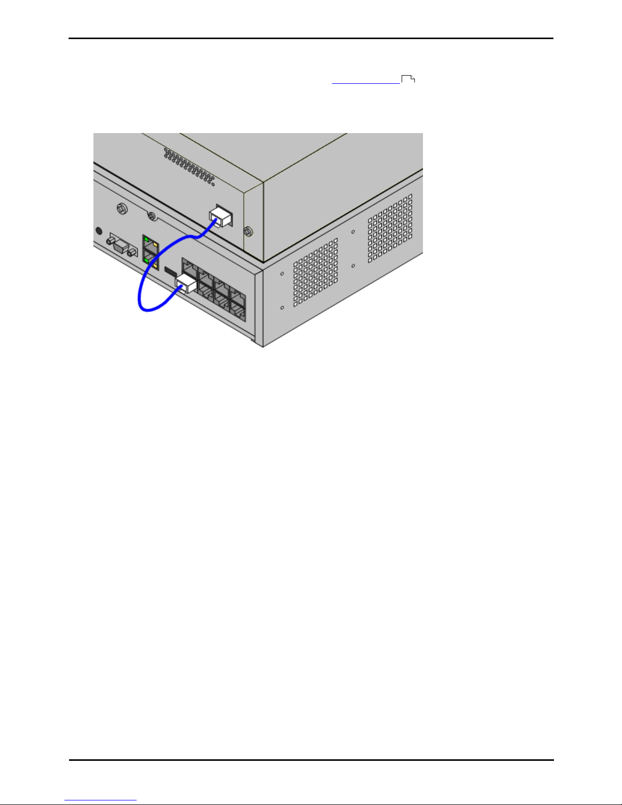
Deploying Avaya IP Office™ Platform IP500 V2 Page 86
15-601042 Issue 30j (18 May 2015)IP Office™ Platform 9.1
Comments on this document? [email protected]
Procedure
1.External expansion modules should not be attached to a control unit that has power.
2.If the IP Office system is being installed in a rack, attach the rack mounting kit to the expansion module.
3.Attach the external expansion module's power supply but do not switch power on.
4.Connect the expansion interconnect cable from the module's EXPANSION port to the EXPANSION port on the
control unit. Make careful note of the port used and include this detail on the cable label and any other system
records.
84
Page 87
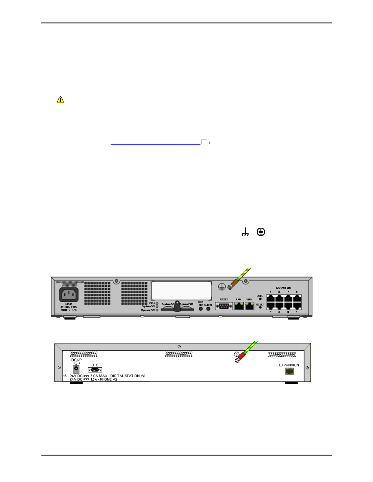
Deploying Avaya IP Office™ Platform IP500 V2 Page 87
15-601042 Issue 30j (18 May 2015)IP Office™ Platform 9.1
Comments on this document? [email protected]
Installing the Physical System: Connecting External Expansion Modules
7.4 Grounding
Use of ground connections reduces the likelihood of problems in most telephony and data systems. This is especially
important in buildings where multiple items of equipment are interconnected using long cable runs, for example phone
and data networks.
All IP Office control units and external expansion modules must be connected to a functional ground. Where the unit is
connected to a power outlet using a power cord with an earth lead, the power outlet must be connected to a protective
earth.
In some cases, such as ground start trunks, in addition to being a protective measure this is a functional requirement for
the equipment to operate. In other cases it may be a locale regulatory requirement and or a necessary protective step,
for example areas of high lightning risk.
· WARNING
During installation do not assume that ground points are correctly connected to ground. Test ground points before
relying on them to ground connected equipment.
· Additional protective equipment
In addition to grounding, additional protective equipment will be required in the following situations.
· On any Digital Station or Phones external expansion module connected to an extension located in another
building. Refer to "Out of Building Telephone Installations ".
· In the Republic of South Africa, on all Analog Trunk external expansion modules (ATM16) and on any control
units containing an analog trunk cards (ATM4/ATM4U).
Tools Required
· o M4 Cross-Head Screwdriver.
· o Tools suitable for crimping a cable spade.
Parts and Equipment Required
· o 14AWG Solid copper wire for ground connection.
· o Cable sleeve matching local regulator requirements. Typically green for a functional ground and green/yellow for
a protective ground.
The ground point on IP Office control units and expansion modules are marked with a or symbol. Ground
connections to these points should use a 14 AWG solid wire with either a green sleeve for a functional ground or green
and yellow sleeve for a protective ground.
IP500 V2 Control Unit
On IP500 V2 control units the ground point is located above the RS232 DTE port.
External Expansion Modules
On expansion modules, the ground point is a 4mm screw located towards the right on the rear of the module.
· On some older modules, the dedicated ground point screw is not present. In those cases, the top-center cover
fixing screw (3mm) can be used as an alternative ground connection point. A toothed washer should be added to
ensure good contact.
36
Page 88

Deploying Avaya IP Office™ Platform IP500 V2 Page 88
15-601042 Issue 30j (18 May 2015)IP Office™ Platform 9.1
Comments on this document? [email protected]
7.5 Network Connection
The section below details how a new IP Office system determines what IP address it should use.
IP Address and DHCP Mode Resolution
When a defaulted or new IP Office control unit is switched on, it requests IP address information from a DHCP Server on
the network. This operation will occur whether a LAN cable is connected or not. The process below is done separately for
both the LAN port (LAN1 in the configuration) and the WAN port (LAN2 in the configuration) on the back of the IP Office
control unit.
· The syste, makes a DHCP request for what IP address information it should use.
· If a DHCP server responds within approximately 10 seconds, the control unit defaults to being a DHCP client and
uses the IP address information supplied by the DHCP server.
· If no DHCP Server responds, the control unit still defaults to being the DHCP client but assumes the following
default addresses:
· LAN Port (LAN1): 192.168.42.1/255.255.255.0.
· WAN Port (LAN2): 192.168.43.1/255.255.255.0.
· Note that the IP Office does not check that these addresses are valid and or available on the network.
· Systems running in IP Office standard modes can be configured as a DHCP server. They can also be configured to
only provide DHCP for Avaya IP phones and or for remote access dial-in connections. DHCP Server options are not
supported for systems running in IP Office Basic Edition modes.
· ! Once an IP500 V2 control unit has obtained IP address and DHCP mode settings, it will retain those settings
even if rebooted without a configuration file present on the System SD card. To fully remove the existing IP
address and DHCP mode settings, the IP Office must be defaulted using IP Office Manager.
PC Connection
Depending on the conditions that applied when the IP Office control unit was first started, a PC can be connected as
follows:
· If the IP Office is not connected to a network:
Connect the PC directly to the IP Office. It must be set to an address valid on the same network as the IP Office
defaults above.
· If the IP Office is connected to a network with no DHCP server:
Connect the PC directly to the IP Office. It must be set to an address valid on the same network as the IP Office
defaults above.
· If the IP Office is connected to a network with a DHCP server:
Connect the PC to the network. It must be set to be a DHCP client or to an address that is valid for the network.
Page 89
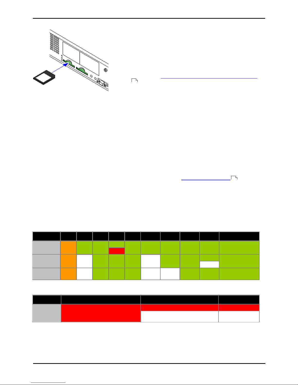
Deploying Avaya IP Office™ Platform IP500 V2 Page 89
15-601042 Issue 30j (18 May 2015)IP Office™ Platform 9.1
Comments on this document? [email protected]
Installing the Physical System: Network Connection
7.6 Starting the System
1.With the IP500 V2 control unit shut down or unpowered, insert the
Avaya System SD card into the System SD slot on the rear of the
control unit.
· On newer controls units, the SD card slots are partially covered by a
plastic tab. Partial release the screw holding the tab so that it can be
moved clear of the required card slot.
· Ensure that you have the correct card.
· Ensure that the card has the level of software required. If necessary
the card can be upgraded to match the version of IP Office Manager
.
2.Apply power to the external expansion modules if any. The power outlet
used must include a switch and in cases where the power cord includes
an earth lead, that outlet must have a protective earth connection.
3.Apply power to the IP500 V2 control unit. The power outlet used must
include a switch and the power outlet must have a protective earth
connection.
4.The control unit will begin loading firmware from the System SD card
with which it will upgrade itself and the components installed in the
control unit.
5.This process takes approximately a minute. The end of this process will
be indicated by LED1 on each base card flashing every 5 seconds. LED9
on each base card fitted with a trunk daughter card will also flash every
5 seconds.
6.The control unit will then begin upgrading the external expansion
modules. This will be indicated by the red center LED on each module
flashing red. The process is completed when the LED changes to steady
green.
7.If a configuration file is already present on the System SD card it is
loaded by the IP Office. If not, the IP Office creates a default
configuration based on the components of the system and copies that
configuration onto the System SD card.
8.It should be possible now to use IP Office Manager to access the
configuration of the IP Office.
Control Unit LEDs
The LEDs on the rear of the control unit go through the following sequence during a normal start up. Note that the times
are approximately only:
LED4s4s
12s5s2s5s5s
10s
10s
Finished
CPU
Orange
Green
Green
Green
Green
Green
Green
Green
Green
Green
Red
System SD
Orange
Off
Green
Green
Green
Off
Green
Green
Green
Green
Flash
Optional SD
If present.
Orange
Off
Green
Green
Green
Off
Off
Green
Green
Green
On the front of the control unit, LED1 on any IP500 base cards fitted is used as follows. LED9 is also used for any trunk
daughter cards fitted.
LED
30s
30s
Finished
LED1/LED9
Red
Red
Red
Fast Flash
Flash every 5
seconds
73
75
Page 90
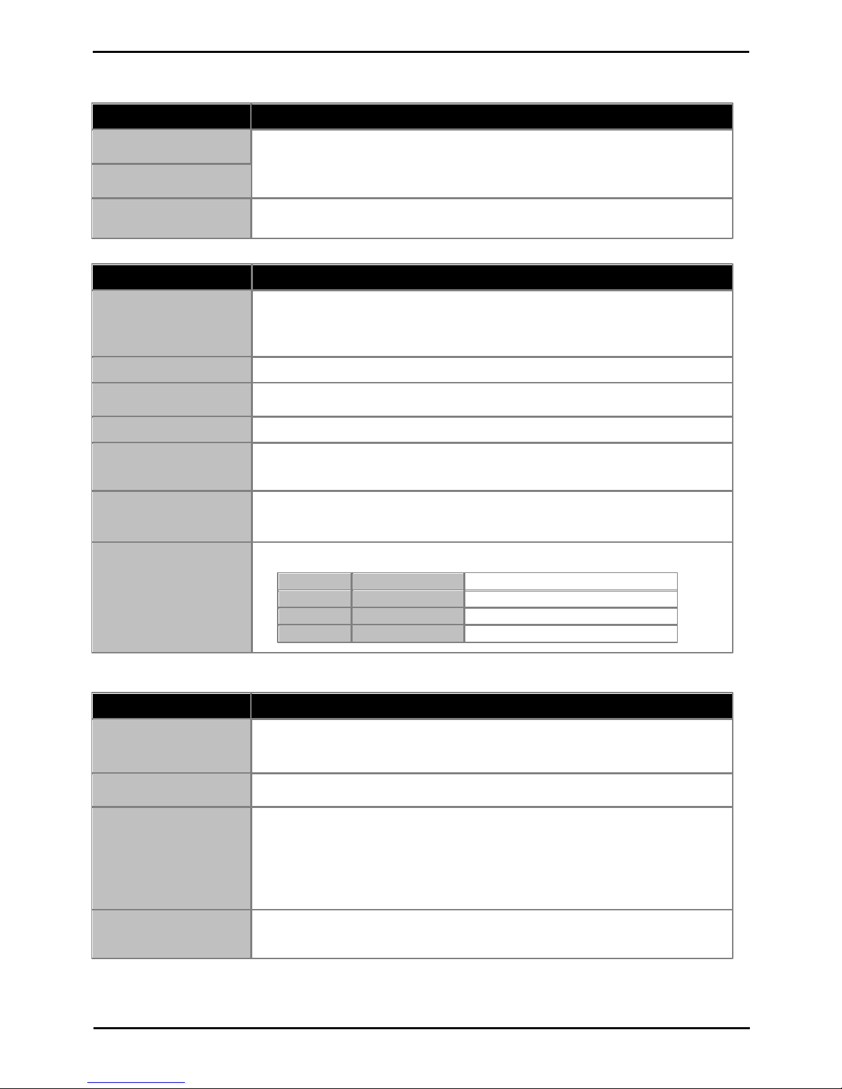
Deploying Avaya IP Office™ Platform IP500 V2 Page 90
15-601042 Issue 30j (18 May 2015)IP Office™ Platform 9.1
Comments on this document? [email protected]
7.7 Checking the LEDs
Control Unit LEDs
LED
Description
Optional SD
· Off = Card shutdown.
· Green on = Card present.
· Green flashing = Card in use.
· Orange steady = Reset imminent.
· Red flashing = Card initializing or
shutting down.
· Red fast flashing = card full
· Red steady = Card failure/wrong type.
System SD
CPU
· Alternate red/green = Starting up.
· Green on = Okay.
· Red on = No software.
· Flashing Red = Error/Shutdown.
Base Card LEDs
Base Card
LEDs 1 to 8 Usage
All Cards
· LED1 is also used for base card status:
· Red On = Error
· Red Slow Flash = Initializing.
· Red Flash every 5 seconds = Card
okay.
· Red Fast Flash = System shutdown.
IP500 Analog Phone
· No status LEDs are used for analog phone extensions.
IP500 Digital Station
· Green Flashing = Phone detected.
· Green On = Phone active.
IP500 TCM8
· Green On = Phone detected.
IP500 Combination
· LEDs 1 to 6
· Green Flashing = Phone detected.
· Green On = Phone active.
IP500 VCM
· LEDs 1 to 8 are unlabelled. They are used to indicate voice compression channel usage.
Each LED lit represents 12.5% of the available voice compression channel capacity in
use (total card capacity rather than licensed capacity).
IP500 4-Port Expansion
· LEDs 1 to 8 are used for the expansion ports on the rear of the control unit. LEDs 9 to
12 are used for the card's own expansion ports.
Green
On
Expansion module present.
Red
Flashing
Initializing.
RedOnError.
Orange
Regular Flash
Base card okay.
Trunk Daughter Card LEDs
Trunk Daughter Card
LEDs 9 to 12 Usage
All cards
· LED 9 is also used for daughter card status.
· Red On = Error
· Red Slow Flash = Initializing.
· Red Flash every 5 seconds = Card okay.
· Red Fast Flash = System shutdown.
Analog Trunk
· Green on = V1: Card installed. V2: Line connected to the port but idle.
· Green flashing = Line in use.
PRI Trunk
· Off = No trunk present.
· Green on = Trunk present.
· Green flashing = Trunk in use.
· Red/Green Fast Flash (port 9) or Green Fast Flash (port 10) = Alarm indication
signal (AIS) from the trunk remote end.
· Red with Green Blink (port 9) or Green Blink (port 10) = Port in loopback mode
(set through IP Office System Monitor).
BRI Trunk
· Off = No trunk present.
· Green on = Trunk present.
· Green flashing = Trunk in use.
Page 91
Deploying Avaya IP Office™ Platform IP500 V2 Page 91
15-601042 Issue 30j (18 May 2015)IP Office™ Platform 9.1
Comments on this document? [email protected]
Installing the Physical System: Checking the LEDs
External Expansion Module LEDs
Module
LEDs
All
The center LED on all external expansion modules is used to indicate the overall state of
the module as follows:
· Red flashing = Module starting up/Loading firmware.
· Red on = Error.
· Green on = Module okay.
· Green flashing = Module starting up/Loading firmware (IP500 DS16A/30A module
only).
Analog Trunk 16
· None.
BRI So8
· Green On = Connected.
· Green Flashing = Activity.
Digital Station 16/30
· Green Flashing = Phone detected.
· Green On = Phone active.
Digital Station 16A/30A
· Green On = Phone detected.
Phone
· None.
Page 92

Deploying Avaya IP Office™ Platform IP500 V2 Page 92
15-601042 Issue 30j (18 May 2015)IP Office™ Platform 9.1
Comments on this document? [email protected]
7.8 Connecting Phones
During initial power up, the IP Office automatically creates extension and user entries for all analog and digital extension
ports (DS and BST) in the system. This allows those devices to be connected without any additional programming.
· ! Warning
If the system has been upgraded from a previous release of IP Office software, all phones will be restricted from
making any calls until a system upgrade license has been entered. The dialing restriction includes not being
able to make emergency calls.
· This section does not cover the installation of DECT, H323 and SIP telephones. For installation of those devices
refer to the appropriate supplementary installation manuals.
7.8.1 Analog Phones
Connect any analog phones to their appropriate Phone ports. Ensure that those connected to power failure ports
are clearly labeled as such.
7.8.2 ETR Phones
Connect any ETR phones to their appropriate ETR ports. These phones do not need to load additional firmware.
7.8.3 DS Digital Station Phones
Connect any digital phones to their appropriate DS ports. These phones may need to upgrade their firmware to match
that supported by the IP Office core software. The appropriate firmware is supplied with the IP Office Manager software
and copied onto the System SD card for IP500 V2 systems.
The phones will automatically load the firmware from the IP Office system if necessary.
· The upgrade process takes approximately 10 minutes during which time the phone will display a warning. The
phone should not be disconnected during this process.
· Once the phone connected to a port has been upgraded, the IP Office will not check whether the phone on that
port needs to be upgraded again except following a system reboot, i.e. multiple phones cannot be upgraded by
swapping the connected phones on the same port.
7.8.4 TCM/BST Phones
Connect any BST phones to their appropriate BST ports. These phones do not need to load additional firmware.
DS30B Module
The IP500 DS16B and DS30B external expansion modules support either BST or DS ports. The port type for a whole
module is configured using IP Office Manager. See DS16B/30B Port Mode Selection .
Default Buttons
For system's with BST phone ports, when a phone is first connected to the port, the button programming of the
associated user is overwritten with the default button programming appropriate for the phone model.
If the new system is being installed with a pre-staged configuration that include user button programming, the automatic
defaulting of buttons to match the phone type will overwrite the user button settings. This behavior can be prevented by
adding the following short code to the user's setup in the pre-programmed configuration:
· Code: *DCP
· Feature: Dial
· Telephone Number: 84000004,1,1,0
The 4000004 part of the string above can also be used to adjust the defaults for the following phone settings:
· The first digit sets the phone contrast = 1 (low) to 9 (high).
· The last digit sets the ringer volume = 0 (high) to 7 (low).
Note that subsequently removing this short code will cause the buttons to return to defaulting according to the phone
type.
Phone Type Setting
For some phones, the phone can only report its general type to the system rather than its specific model. It is
recommended that after connecting all the phones, the phone types should be correctly set in the IP Office configuration.
362
358 49
354
353
110
Page 93
Deploying Avaya IP Office™ Platform IP500 V2 Page 93
15-601042 Issue 30j (18 May 2015)IP Office™ Platform 9.1
Comments on this document? [email protected]
Installing the Physical System: Connecting Phones
· ! Important
The default types cannot be changed after installation without defaulting the configuration. Therefore you must
ensure that you connect the correct type of phone to each port. If you need to swap phones, uses the process for
exchanging extension numbers rather than swapping wiring.
1.Using IP Office Manager, receive the configuration from the system.
2.Select Extension.
3.Selecting each extension in turn, on the Extn tab, check that the Device Type field is set to the correct phone
model.
Default Type
Possible Phone Models
T7100
T7100, M7100, M7100N, Audio Conferencing Unit.
T7208
T7208, M7208, M7208N.
M7310
T7406E, T7406, M7310, M7310N
M7310BLF
T7316, M7310BLF
M7324
M7324, M7324N
4.Save the configuration back to the IP Office system.
7.8.5 IP/SIP Phones
The installation and configuration of H323 and SIP IP telephones is not covered by this document. Refer to the
appropriate IP Office installation manual for the type of phone being installed.
169
Page 94

Page 95

Deploying Avaya IP Office™ Platform IP500 V2 Page 95
15-601042 Issue 30j (18 May 2015)IP Office™ Platform 9.1
Comments on this document? [email protected]
Initial Configuration Using IP
Office Manager
Chapter 8.
Page 96

Deploying Avaya IP Office™ Platform IP500 V2 Page 96
15-601042 Issue 30j (18 May 2015)IP Office™ Platform 9.1
Comments on this document? [email protected]
8. Initial Configuration Using IP Office Manager
This section covers basic configuration changes required for IP Office systems if using the IP Office Manager application.
This covers just the basic configuration, the full range of configuration possible through IP Office Manager is covered in
the IP Office Manager manual.
1.Initial Configuration
The Initial Configuration menu is shown the first time that IP Office Manager connects to a new system.
2.Enter Licenses
Enter licenses for features that require them.
3.Set the System Locale
Setting the correct system locale affects a wide range of settings including trunk settings. The correct locale must
be set for a system to operate correctly.
4.Set the Extension Numbering
Renumber the user extensions if required.
5.Change the IP Address/DHCP Settings
If necessary, the IP address and DHCP mode of the IP Office system can be changed.
6.Remove any Unused Trunks
Disabling the use of trunks and trunk channels that are not available.
7.Select the Clock Source for Digital Lines
Altering which digital trunk is used to provide the IP Office with its clock signal for call synchronization.
8.Enter Trunk Prefixes
On systems where a prefix is being used for external dialing, ensure that the same prefix is added to incoming
numbers in order to allow return calls.
9.DS16B/30B Port Mode Selection
These modules can support Avaya T-Series and M-Series phones by providing BST ports or other Avaya digital
phones by providing DS ports. The port type selection for the whole module is done using IP Office Manager.
97
99
100
102
101
104
106
108
110
Page 97
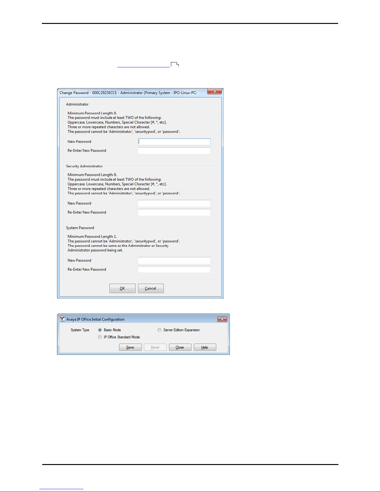
Deploying Avaya IP Office™ Platform IP500 V2 Page 97
15-601042 Issue 30j (18 May 2015)IP Office™ Platform 9.1
Comments on this document? [email protected]
Initial Configuration Using IP Office Manager:
8.1 Initial Configuration
Unless the System SD card contained a pre-built configuration, IP Office Basic Edition is the default mode assumed by a
new or defaulted control unit.
To start the initial configuration:
1.Using IP Office Manager, connect to the system and receive its configuration. The default name and password
are both Administrator.
2.When IP Office Manager is first connected to the new system, you are prompted to change the default
passwords.
3.Enter the new password or passwords and click OK. Once the password changes are confirmed, the Initial
Configuration menu is displayed, prompting you to confirm the required operating mode for the system.
4.Select IP Office Standard Mode and click Save.
68
Page 98
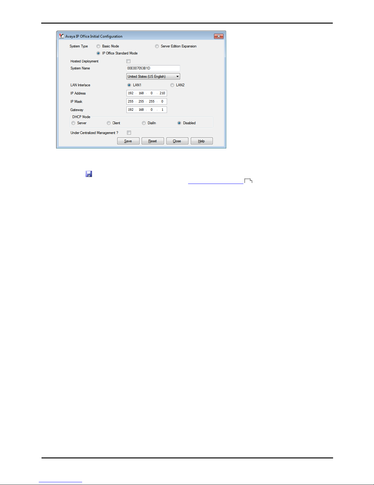
Deploying Avaya IP Office™ Platform IP500 V2 Page 98
15-601042 Issue 30j (18 May 2015)IP Office™ Platform 9.1
Comments on this document? [email protected]
5.The menu prompts you for additional settings:
6.Check that the settings match those required for the customer site.
7.Click Save. The new configuration is opened in IP Office Manager.
8.Click on the save icon and save the updated configuration back to the IP Office system. Once the system has
rebooted, you can continue with the initial configuration using IP Office Manager .
96
Page 99

Deploying Avaya IP Office™ Platform IP500 V2 Page 99
15-601042 Issue 30j (18 May 2015)IP Office™ Platform 9.1
Comments on this document? [email protected]
Initial Configuration Using IP Office Manager: Initial Configuration
8.2 Entering Licenses
For IP500 V2 control units, license files can be pre-loaded onto the System SD card. Those licenses will then be
merged with the configuration when the control unit is powered up. Otherwise for all control units, licenses are entered
into the configuration using IP Office Manager. In addition to the methods below, license can also be added by placing the
addition licenses as a text file on the System SD card .
You must ensure that the licenses being entered have been issue against the FK serial number of the System SD card
fitted in the system. Each license is a unique 32-character string based on the feature being licensed and the serial
number of the SD card plugged into the system control unit.
Entering licenses manually is liable to errors caused by miskeying the correct 32-character string.
To enter licenses:
1.Start IP Office Manager and receive the configuration from the IP Office system.
2.Select System.
3.The field Dongle Serial Number shows the serial number of the System SD card fitted to the system. Check that
this number matches the one against which the licenses have been issued.
4.Select License.
5.To add a license, click Add... .
6.For the license type select ADI and click OK.
7.Enter the new license key and click OK. We recommend that add licenses by cut and pasting them from a supplied
file listing each 32-character license keys. That avoids potential issues with mistyping.
8.The Status of the new license should show Unknown and name the license as expected. If the name is Invalid,
the most likely cause is incorrect entry of the license key characters.
9.Click on the save icon to send the configuration back to the IP Office.
10.Use IP Office Manager to receive the configuration again and check that the status of the license. It should now
be Valid.
75 361
75
68
Page 100

Deploying Avaya IP Office™ Platform IP500 V2 Page 100
15-601042 Issue 30j (18 May 2015)IP Office™ Platform 9.1
Comments on this document? [email protected]
8.3 Setting the System Locale
Setting the correct system locale affects a wide range of settings including trunk settings. The correct locale must be
set for a system to operate correctly. It will also set the default language used for phone displays and for voicemail
prompts. However language settings can be changed separately from the system locale if different language operation is
required.
· ! WARNING
This process requires the IP Office system to reboot in order to complete the changes. The reboot ends any
current calls and services.
· This process can be performed through phone based administration from either of the first two systems in the
system. For details, refer to the Phone Based Administration manual.
To set the system locale:
1.Start IP Office Manager and receive the configuration from the IP Office system.
2.Click on System.
3.Click on the System tab.
4.Use the Locale drop down list to select the required locale. The default language for the locale is shown in
brackets, for some locales there may be more than one entry with different default languages for each.
· The supported countries are Argentina, Australia, Bahrain, Belgium, Brazil, Canada, Chile, China,
Czech, Denmark, Egypt, Finland, France, Germany, Greece, Hong Kong, Hungary, Iceland, India,
Italy, Japan, Korea, Kuwait, Mexico, Morocco, Netherlands, New Zealand, Norway, Oman, Pakistan,
Peru, Philippines, Poland, Portugal, Qatar, Russia, Saudi Arabia, Singapore, South Africa, Spain,
Sweden, Switzerland, Taiwan, Turkey, United Arab Emirates, United States, Venezuela.
· If the option Customize is selected, the following additional fields are available:
· Tone Plan: Default = Tone Plan 1
Select a tone plan to be used for different ringing signals such as dial tone and ring tone.
· CLI Type: Default = FSK V23
Set the method for passing caller ID information to analog extensions. The options are DTMF, FSK Bell
202 or FSK V23.
· IP500 V2 Systems: If the system is configured to use Embedded Voicemail (the default for a new system),
and the correct set of language prompts to match the locale are not present on the System SD card, IP Office
Manager displays an error. The Add/Display VM locales option (File | Advanced | Add/Display VM locales)
can be used to upload the language prompts from IP Office Manager.
5.Click on the save icon and save the updated configuration back to the IP Office system.
43
68
 Loading...