

Page 1
Local: 863-614-1900 Toll Free: 866-770-4930 Fax: 888-782-3072
TelephonemanOfAmerica.com or shop.telephonemanofamerica.com
TELEPHONE MAN OF AMERICA
Earning Your Business Every Step of the Way!
Specializing in Telecom Equipment of all Brands, Carrier Services, Technician
Services, Maintenance Agreements and Purchasing Excess Telecom Equipment!
I will always do my best to match or beat any competitors bid!
Page 2

IP Office Essential Edition
PARTNER Version Reference
- Issue 1a - (30 January 2010)
Page 3

© 2010 AVAYA All Rights Reserved.
Notice
While reasonable efforts were made to ensure that the information in this document was complete and accurate at the time of
printing, Avaya Inc. can assume no liability for any errors. Changes and corrections to the information in this document may be
incorporated in future releases.
Documentation Disclaimer
Avaya Inc. is not responsible for any modifications, additions, or deletions to the original published version of this
documentation unless such modifications, additions, or deletions were performed by Avaya.
Link Disclaimer
Avaya Inc. is not responsible for the contents or reliability of any linked Web sites referenced elsewhere within this
Documentation, and Avaya does not necessarily endorse the products, services, or information described or offered within
them. We cannot guarantee that these links will work all of the time and we have no control over the availability of the linked
pages.
License
USE OR INSTALLATION OF THE PRODUCT INDICATES THE END USER’S ACCEPTANCE OF THE TERMS SET FORTH
HEREIN AND THE GENERAL LICENSE TERMS AVAILABLE ON THE AVAYA WEBSITE AT
http://support.avaya.com/LicenseInfo/ (“GENERAL LICENSE TERMS”). IF YOU DO NOT WISH TO BE BOUND BY THESE
TERMS, YOU MUST RETURN THE PRODUCT(S) TO THE POINT OF PURCHASE WITHIN TEN (10) DAYS OF DELIVERY
FOR A REFUND OR CREDIT.
Avaya grants End User a license within the scope of the license types described below. The applicable number of licenses and
units of capacity for which the license is granted will be one (1), unless a different number of licenses or units of capacity is
specified in the Documentation or other materials available to End User. “Designated Processor” means a single stand-alone
computing device. “Server” means a Designated Processor that hosts a software application to be accessed by multiple users.
“Software” means the computer programs in object code, originally licensed by Avaya and ultimately utilized by End User,
whether as stand-alone Products or pre-installed on Hardware. “Hardware” means the standard hardware Products, originally
sold by Avaya and ultimately utilized by End User.
License Type(s): Designated System(s) License (DS).
End User may install and use each copy of the Software on only one Designated Processor, unless a different number of
Designated Processors is indicated in the Documentation or other materials available to End User. Avaya may require the
Designated Processor(s) to be identified by type, serial number, feature key, location or other specific designation, or to be
provided by End User to Avaya through electronic means established by Avaya specifically for this purpose.
Copyright
Except where expressly stated otherwise, the Product is protected by copyright and other laws respecting proprietary rights.
Unauthorized reproduction, transfer, and or use can be a criminal, as well as a civil, offense under the applicable law.
Third-Party Components
Certain software programs or portions thereof included in the Product may contain software distributed under third party
agreements (“Third Party Components”), which may contain terms that expand or limit rights to use certain portions of the
Product (“Third Party Terms”). Information identifying Third Party Components and the Third Party Terms that apply to them is
available on Avaya’s web site at: http://support.avaya.com/ThirdPartyLicense/
Avaya Fraud Intervention
If you suspect that you are being victimized by toll fraud and you need technical assistance or support, call Technical Service
Center Toll Fraud Intervention Hotline at +1-800-643-2353 for the United States and Canada. Suspected security
vulnerabilities with Avaya Products should be reported to Avaya by sending mail to: [email protected].
For additional support telephone numbers, see the Avaya Support web site (http://www.avaya.com/support).
Trademarks
Avaya and the Avaya logo are registered trademarks of Avaya Inc. in the United States of America and other jurisdictions.
Unless otherwise provided in this document, marks identified by “®,” “™” and “SM” are registered marks, trademarks and
service marks, respectively, of Avaya Inc. All other trademarks are the property of their respective owners.
Documentation information
For the most current versions of documentation, go to the Avaya Support web site (http://www.avaya.com/support) or the IP
Office Knowledge Base (http://marketingtools.avaya.com/knowledgebase/).
Avaya Support
Avaya provides a telephone number for you to use to report problems or to ask questions about your contact center. The
support telephone number is 1 800 628 2888 in the United States. For additional support telephone numbers, see the Avaya
Web site: http://www.avaya.com/support.
PARTNER® Version, Installation and Reference Manual Page 2
- Issue 1a (30 January 2010)IP Office Essential Edition
Page 4

Contents
Introduction1.
..................................................................... 81.1 How this book is structured
..................................................................... 81.2 RoHS
..................................................................... 91.3 Repair
..................................................................... 91.4 Equipment Availability
..................................................................... 91.5 Web Sites
..................................................................... 91.6 Training
System Overview2.
..................................................................... 142.1 Partner® Features
..................................................................... 152.2 Partner® Constraints
..................................................................... 162.3 System Components
..................................................................... 172.4 Control Unit
..................................................................... 182.5 SD Card
..................................................................... 192.6 Base Cards
..................................................................... 202.7 Trunk Cards
..................................................................... 212.8 SIP Cards
..................................................................... 212.9 External Expansion Module
..................................................................... 222.10 Supported Phones
..................................................................... 232.11 Dial Plan
..................................................................... 232.12 Core Software & BIN Files
..................................................................... 242.13 Power Supplies
............................................................................ 242.13.1 Power Supply Backup
Installing PARTNER®3.
..................................................................... 283.1 IP Office Manager
..................................................................... 293.2 Getting Started
............................................................................ 293.2.1 Unpacking
............................................................................ 293.2.2 Environmental Requirements
............................................................................ 303.2.3 Read the Documentation
............................................................................ 303.2.4 Space Requirements
............................................................................ 313.2.5 Tools and Parts Required
............................................................................ 323.2.6 Cabling and Cables
............................................................................ 333.2.7 Grounding
............................................................................ 333.2.8 Rack Mounting
............................................................................ 363.2.9 Wall Mounting
3.2.10 Lightning Protection/Out-of-Building
............................................................................ 38
Connections
..................................................................... 383.3 Install Overview
..................................................................... 393.4 Card Installation
..................................................................... 413.5 Starting
..................................................................... 423.6 Connections
..................................................................... 423.7 Final Actions
System Component Details4.
..................................................................... 464.1 Control Unit
............................................................................ 474.1.1 Rear Connections
..................................................................... 484.2 SD Card
..................................................................... 494.3 Base Cards
............................................................................ 504.3.1 Digital Station
............................................................................ 514.3.2 Analog Phone
............................................................................ 524.3.3 ETR6 Card
............................................................................ 544.3.4 ATM Combination Card
..................................................................... 554.4 Trunk Cards
............................................................................ 564.4.1 Analog Trunk Card
............................................................................ 564.4.2 PRI Trunk Cards
Contents
..................................................................... 574.5 Expansion Modules
............................................................................ 574.5.1 Digital Station
............................................................................ 594.5.2 Phone Module
..................................................................... 614.6 Telephones
............................................................................ 614.6.1 1416
............................................................................ 614.6.2 1408
............................................................................ 624.6.3 1403
............................................................................ 634.6.4 ETR34D
............................................................................ 644.6.5 ETR6D
............................................................................ 654.6.6 ETR18D
............................................................................ 654.6.7 ETR34
............................................................................ 664.6.8 ETR18
............................................................................ 674.6.9 ETR6
............................................................................ 684.6.10 3910
............................................................................ 684.6.11 3920
............................................................................ 694.6.12 POTS
............................................................................ 704.6.13 Phone Add-Ons
..................................................................... 714.7 Out of Building Telephone Installations (COPY)
............................................................................ 724.7.1 DS Phones
............................................................................ 724.7.2 Analog Phone Barrier Box
............................................................................ 734.7.3 Rack Mounting Barrier Boxes
..................................................................... 754.8 Associated Applications
............................................................................ 754.8.1 Voicemail
............................................................................ 764.8.2 System Status Application (SSA)
............................................................................ 764.8.3 Monitor
............................................................................ 774.8.4 TAPI
............................................................................ 784.8.5 Call Logging Applications
..................................................................... 784.9 Physical Ports
............................................................................ 784.9.1 ANALOG Port
............................................................................ 794.9.2 Audio Port
............................................................................ 794.9.3 DS Ports
............................................................................ 804.9.4 ETR Port
............................................................................ 804.9.5 Expansion Port
............................................................................ 804.9.6 EXT O/P Port
............................................................................ 814.9.7 LAN Port
............................................................................ 814.9.8 PF Port
............................................................................ 824.9.9 Phone (POT) Port
............................................................................ 834.9.10 PRI Port
............................................................................ 834.9.11 RS232 DTE Port
Administration5.
..................................................................... 885.1 Initial Configuration
..................................................................... 885.2 Changing the Default Password
..................................................................... 895.3 SD Card Actions
............................................................................ 895.3.1 Removing SD Cards
............................................................................ 905.3.2 Directories and Files
............................................................................ 915.3.3 Booting from the SD Cards
............................................................................ 915.3.4 SD Card Removal
............................................................................ 925.3.5 Recreating an IP Office SD Card
............................................................................ 935.3.6 Backing Up the System SD Card
..................................................................... 945.4 External Trunk Configuration
............................................................................ 945.4.1 Clock Quality
............................................................................ 955.4.2 Unused Trunks
..................................................................... 955.5 Changing Components
............................................................................ 975.5.1 Running SSA
..................................................................... 975.6 Adding Licences
..................................................................... 985.7 Additional Processes
............................................................................ 985.7.1 Upgrading the System
PARTNER® Version, Installation and Reference Manual Page 3
- Issue 1a (30 January 2010)IP Office Essential Edition
Page 5

............................................................................ 1005.7.2 Upgrading the Core Software
............................................................................ 1005.7.3 Changing the IP Address Settings
............................................................................ 1015.7.4 System Shutdown
............................................................................ 1025.7.5 Rebooting the System
Appendices6.
..................................................................... 1066.1 Troubleshooting
..................................................................... 1086.2 Safety Statements
............................................................................ 1086.2.1 Lightning Protection/Hazard Symbols
............................................................................ 1096.2.2 Trunk Interface Modules
............................................................................ 1096.2.3 Further Information and Product Updates
............................................................................ 1096.2.4 Compliance with FCC Rules
............................................................................ 1096.2.5 Port Safety Classification
............................................................................ 1106.2.6 EMC Directive
..................................................................... 1116.3 Regulatory Instructions for Use
............................................................................ 1116.3.1 Canada
............................................................................ 1116.3.2 FCC Notification
...............................................................................113Index
PARTNER® Version, Installation and Reference Manual Page 4
- Issue 1a (30 January 2010)IP Office Essential Edition
Page 6

Chapter 1.
Introduction
PARTNER® Version, Installation and Reference Manual Page 5
- Issue 1a (30 January 2010)IP Office Essential Edition
Page 7

Page 8
1. Introduction
Introduction:
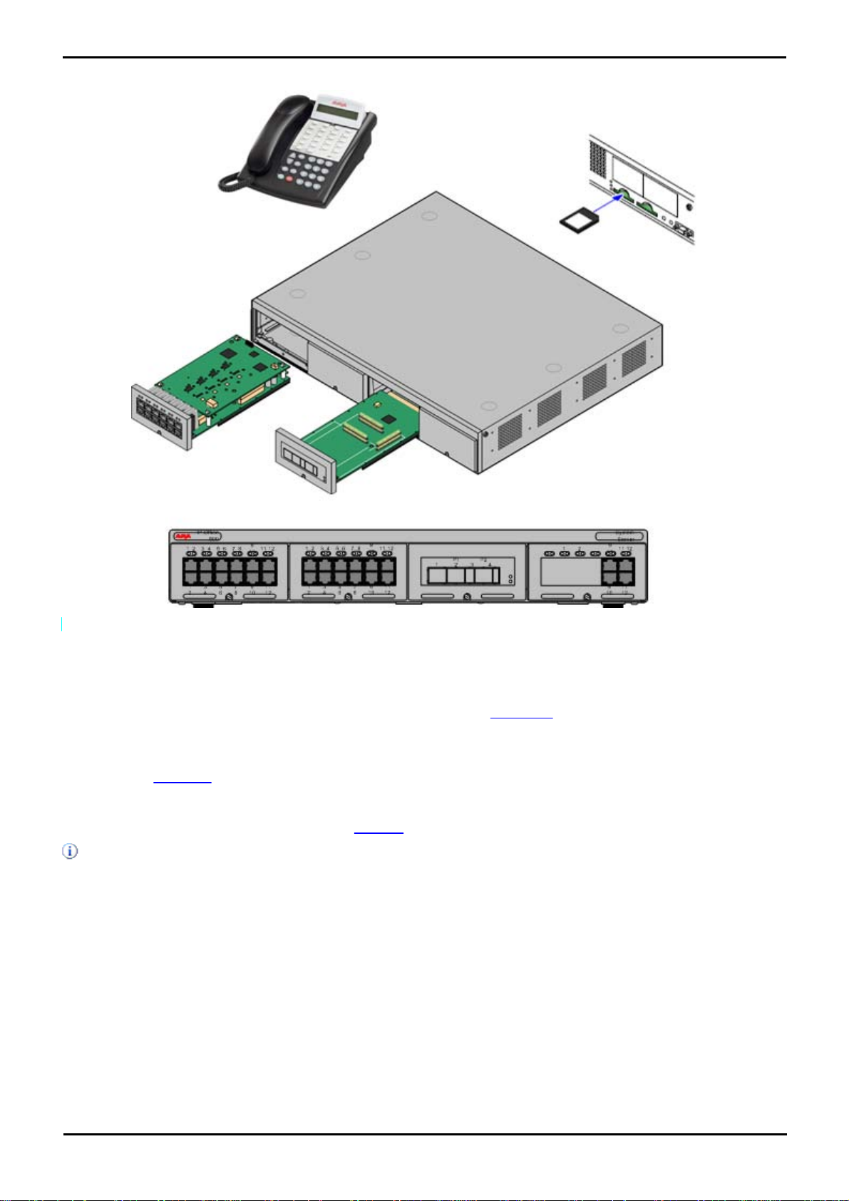
Avaya IP Office Essential Edition - PARTNER® Version is a telephone system designed for single site businesses typically
with 5 to 25 extensions, that need a small business communications solution which is reliable, established, scalable, easy
to use, and can grow as needed. IP Office Essential Edition - PARTNER® Version is an IP / Digital communication system
designed exclusively to meet the unique needs of a small business.
The Essential Edition - PARTNER® Version supports a selection of system telephones, many with displays that show you
programming and operation feedback. But don’t throw that old telephone away, because the Essential Edition PARTNER® Version includes support for many single-line telephones. And you can connect many auxiliary devices, such
as fax machines, answering machines, modems, and credit card scanners, to the system.
On-board basic voice mail eliminates the need for additional hardware.
This document provides system and component descriptions with details to support configuration and maintenance
activities. The main administration and analysis tool used with the Essential Edition - PARTNER® Version is the Essential
Edition - PARTNER® Version admin tool known as Manager which has its own user manual.
For customers or maintainers who do not have access to Manager, almost all settings described in this
document and in the Essential Edition - PARTNER® Version Admin Tool User Manual, can be achieved
through manual TUI commands described in the IP Office Essential Edition ETR Telephone System
Programming User Guide.
Associated documents are:
· IP Office Essential Edition - PARTNER® Version - Quick Install Manual
· IP Office Essential Edition - PARTNER® Version - Administrator Tool Guide
· IP Office Essential Edition - PARTNER® Version - Programming and User Guide
· IP Office Essential Edition - PARTNER® Version - ETR Telephone System Programming and User Guide
· Individual User Guides for associated telephone instruments. (ETR, 1400, 3910, 3920)
IP Office Technical Bulletins
Ensure that you have obtained and read the IP Office Technical Bulletin relating to the IP Office software release which
you are installing. This bulletin will contain important information that may not have been included in this manual. IP
Office Technical Bulletins are available from the Avaya support website http://support.avaya.com).
PARTNER® Version, Installation and Reference Manual Page 7
- Issue 1a (30 January 2010)IP Office Essential Edition
Page 9
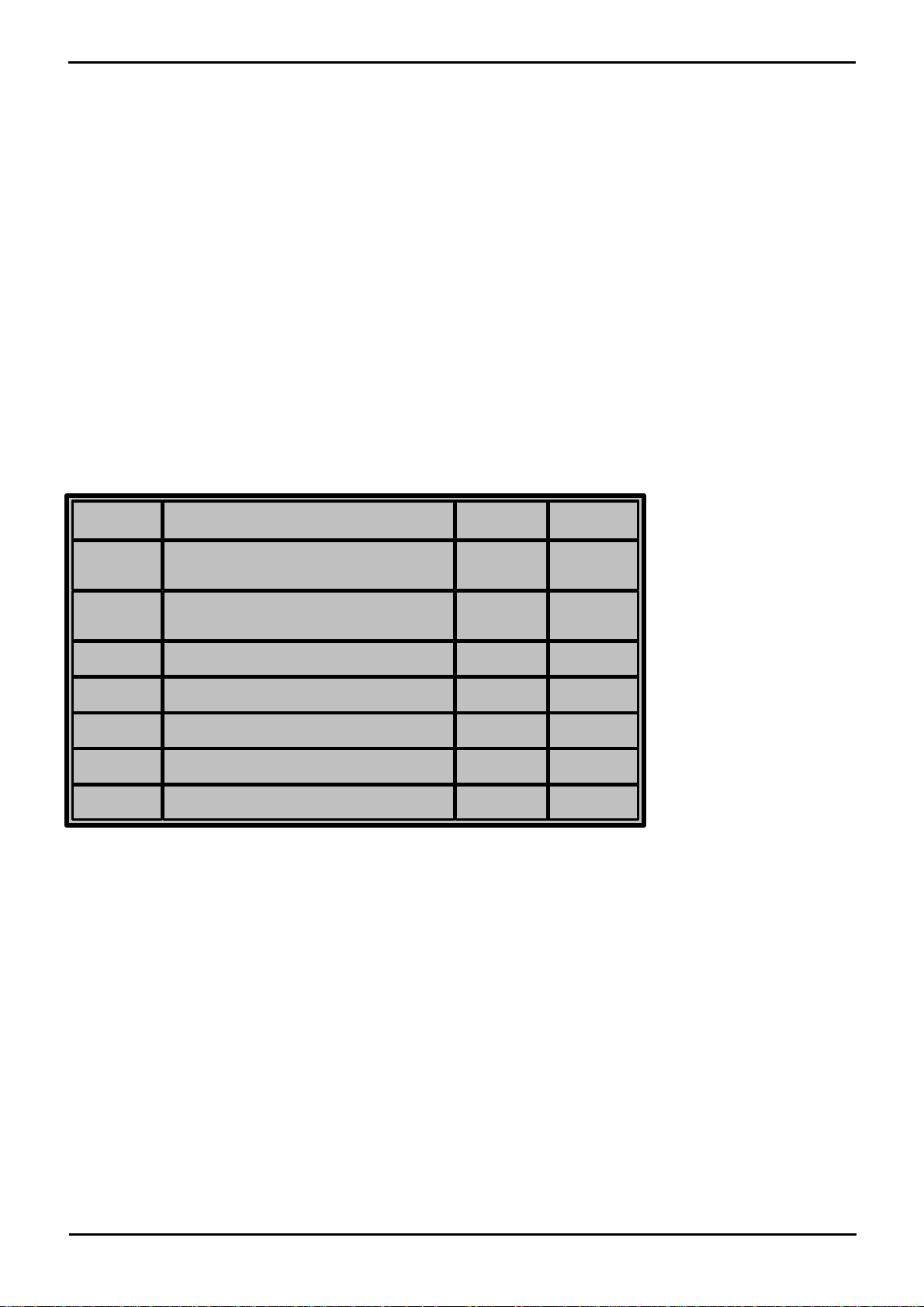
1.1 How this book is structured
Version
Change
Name
Date
Draft 1
Initial issue
V Vella
12 Nov
2009
Draft 2
ER comments
V Vella
20 Nov
2009
Draft 3
Nomenclature correction and edit
V Vella
Draft 4
First review draft
V Vella
12 Jan 2010
Draft 5
Continued editing and review comments
V Vella
22 Jan 2010
Issue 1.0
Issued for final review
V Vella
3 Feb 2010
This book contains seven chapters, which provide information as follows:
Chapter 1, Introduction — briefly details the installation procedure for Essential Edition - PARTNER® and provides
standard Avaya information.
Chapter 2, System Overview — describes the Essential Edition - PARTNER® system structure, the system features,
modes of operation, system capacities.
Chapter 3, Getting Started — briefly describes where and how to mount equipment, equipment checks and unpacking
Chapter 4, Installing IP Office — intended primarily for the technician, explains the physical installation of the control
unit and the telephones.
Chapter 5, Administration — explains how the system configuration can be altered and how software and hardware
can be upgraded as new modules and releases become available.
Chapter 6, System Component Details — descriptions of system components identified in Chapter 2, System
Overview.
Chapter 7, Troubleshooting — how to handle problems occurring during installation and operation. Describes possible
problems with the telephone system and the solutions to these problems.
Appendix — supplementary information
Index
Document History
Document Conventions
The following font attributes are used in this document:
· Bold Used to emphasize, identify commands or highlight menu selections
· Italic Used to identify dialog fields, windows, or documents
· Courier Used for code listings, file names and command line content
1.2 RoHS
RoHS is a European Union directive for the Removal of Certain Hazardous Substances from Electrical and Electronic
Equipment. Similar legislation has been or is being introduced in a number of other countries. Avaya has decided to make
its global product range compliant with the requirements of RoHS.
The actions taken vary:
· In some cases equipment has been discontinued and is no longer available from Avaya.
· In some cases new manufactured stock has been made RoHS compliant and keeps its existing Part number.
· In other cases the equipment has been replaced by a new RoHS compliant alternative with new Part numbers.
PARTNER® Version, Installation and Reference Manual Page 8
- Issue 1a (30 January 2010)IP Office Essential Edition
Page 10

Introduction: RoHS
The Part numbers within this document are for RoHS compliant equipment unless otherwise stated.
1.3 Repair
Essential Edition - PARTNER® Version systems do not contain any user serviceable or repairable components. If a faulty
unit is suspected the whole unit should be replaced.
IP Office 500v2 control units should not be opened under any circumstances.
1.4 Equipment Availability
Part numbers and details of specific items within this documentation are for reference only. Items available in any specific
locale should be confirmed against the local Essential Edition - PARTNER® Version price list for that locale. The local price
list may also include additional items relative to the installation requirements of that locale.
1.5 Web Sites
Information to support the IP Office can be found on a number of web sites.
· Avaya - http://www.avaya.com
The official web site for Avaya. The front page also provides access to individual Avaya web sites for different
countries.
· Avaya Enterprise Portal - http://partner.avaya.com
This is the official web site for all Avaya Business Partners. The site requires registration for a user name and
password. Once accessed, the site portal can be individually customized for what products and information types
you wish to see and to be notified about by email.
· Avaya Support - http://support.avaya.com
Contains documentation and other support materials for Avaya products including IP Office. Copies of the IP Office
CD images are available from this site and updated core software .bin files.
· Avaya IP Office Knowledge Base - http://marketingtools.avaya.com/knowledgebase
Access to an on-line regularly updated version of the IP Office Knowledge Base. Currently this link is only available
to Avaya Business Partners while running an ARA account (Avaya Remote Access) connection.
· Avaya University - http://www.avaya-learning.com This site provides access to the full range of Avaya training courses. That includes both on-line courses, course assessments and access to details of classroom based courses. The site requires users to register in order to provide the user with access to details of their training record. See Training.
· Avaya Community - http://www.aucommunity.com
This is the official discussion forum for Avaya product users. However it does not include any separate area for
discussion of Essential Edition - PARTNER® Version issues.
· Avaya UPS Calculator - http://ups.avayaups.com
An online calculator for uninterruptible power supply (UPS) requirements. Allows specification of a range of
equipment to be supported. See Power Supply Backup (UPS).
· Other Non-Avaya Web Sites
A number of third-party web forums exist that discuss Essential Edition - PARTNER® Version. These can act as
useful source of information about how the Essential Edition - PARTNER® Version is used. Some of these forums
require you to be a member and to register. These are not official Avaya forums and their content is not monitored
or sanctioned by Avaya.
· Tek-Tips: http://www.tek-tips.com.
· IP Office Info: http://www.ipofficeinfo.com.
· Yahoo Groups: http://groups.yahoo.com/group/ipoffice.
· Lycos Forum: http://members.lycos.co.uk/ipoffice.
· PBX Tech: http://www.pbxtech.info/forumdisplay.php?f=8.
1.6 Training
Avaya University provides a wide range of training courses for IP Office and its associated applications. This includes
courses necessary for IP Office resellers to become Avaya Authorized Channel Partners and for individuals to achieve IP
Office certification.
PARTNER® Version, Installation and Reference Manual Page 9
- Issue 1a (30 January 2010)IP Office Essential Edition
Page 11

Details of all the course can be found on the Avaya University web site (http://www.avaya-learning.com). The site can be
used to check course availability and to book course. It also includes on-line courses and on-line course assessments. The
site requires users to setup a user name and password in order to track their personal training record.
PARTNER® Version, Installation and Reference Manual Page 10
- Issue 1a (30 January 2010)IP Office Essential Edition
Page 12

Introduction: Training
PARTNER® Version, Installation and Reference Manual Page 11
- Issue 1a (30 January 2010)IP Office Essential Edition
Page 13

Page 14

Chapter 2.
System Overview
PARTNER® Version, Installation and Reference Manual Page 13
- Issue 1a (30 January 2010)IP Office Essential Edition
Page 15

2. System Overview
This section looks at the components that collectively form the Essential Edition - PARTNER® Version system. This
includes aspects such as cabling and the need for additional non-Avaya IP Office equipment.
The section provides only a general description of individual units. For greater detail, refer to the System
Components section.
2.1 Partner® Features
The following basic features are provided by Essential Edition - PARTNER® Version:
· Prompts and feedback displays on both ETR and 1400 sets, emulate the PARTNER ACS R8 system.
· Integral SD card contains system files, and backup files. Automatic backup every 24 hours
· Up to 48 extensions
· Avaya ETR Telephone support
· Avaya 1400 Digital Telephone support
· Key System Functionality
· Embedded Voicemail
· SIP Trunking (up to 10 trunks)
· Supports the Essential Edition - PARTNER® Version Manager application.
· Supports the System Status Application
· Supports the System Monitor Application
· TAPI
· SMDR
· Supports DS16 Expansion Module (adds 16 additional digital station ports.) and Phone16 Expansion Module (adds
16 additional analog station ports)
· 10-party conferencing
· Supports loudspeaker connectivity via a combination card or one of the 2 built-in POTS port on other cards
· Includes 3 instances of SIP and Mobility.
· Call handling mode will change from key to PBX operation
The following features are pre-assigned:
· Last Number Redial
· Drop
· Recall (CO hook flash)
· Auto Line
· Selection – L1, L2, etc.
· Voice Mail Access, Each extension has voice mailbox assigned with Automatic Voice Mail Coverage turned on.
Control unit slot availability – (maximum of 4 of the following cards):
· Up to 2 Combination cards (each provides 6 DS ports; 2 POTS station ports; 4 POTS line ports; and 10 VCM
channels {supports up to 10 SIP lines})
· Up to 3 Essential Edition - PARTNER® Version ETR6 cards (each provides 6 ETR station ports)
· Up to 3 DS8 cards (each provides 8 digital station ports)
· Up to 3 Phone 8 cards (each provides 8 POTS station ports). Maximum of 3 since a Combination card; DS-8 or
ETR-6 must be present in system
· Up to 3 Phone 2 cards (each provides up to 2 POTS station ports). Maximum of 3 since a Combination card; DS-8
or ETR-6 must be present in system
· An ATM4 daughter card can be added to any ETR6 card or DS card, or Phone card increasing POTS line capacity.
(up to max 3)
· 1 PRI/T1 daughter card may be added to any ETR6 card or DS card or Phone card, increasing digital line capacity.
PARTNER® Version, Installation and Reference Manual Page 14
- Issue 1a (30 January 2010)IP Office Essential Edition
Page 16
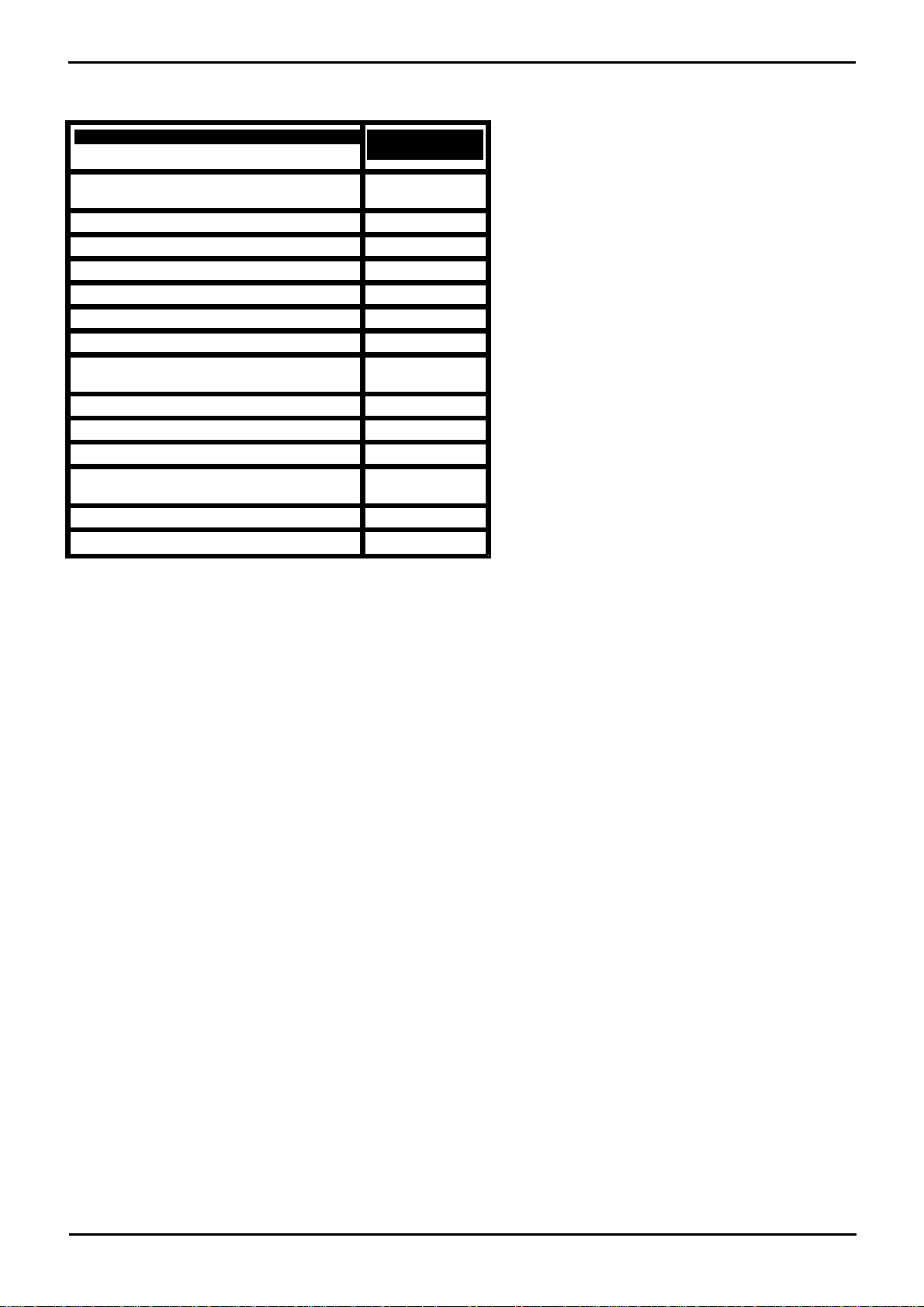
2.2 Partner® Constraints
Max allowed in
system
IP Office Essential Edition - PARTNER®
Version Base Cards:
Phone 8 - Base
3
Phone 2 - Base
3
DS 8 - Base
3
ETR6 – Base
3
6DS+2POTS+VCM10 LE Combination
2
IP Office Essential Edition - PARTNER®
Version Daughter Cards:
ATM 4 Uni - daughter
3
PRI 1 Uni - daughter
1
IP Office Essential Edition - PARTNER®
Version Expansion Modules:
IP Office 500v2 PHONE 16
1
IP Office 500v2 DIGITAL STATION 16
1
System Overview: Partner® Constraints
Essential Edition - PARTNER® Version requires a presence of at least 1 ETR or Digital station to be used for TUI
administration. This needs the presence of at least 1 of the following cards:
· Comination Card
· DS8
· ETR-6
System capacity for the Essential Edition - PARTNER® Version is flexible and can use combinations of the following
hardware components:
Control unit (4 available slots – maximum of 4 of the following cards):
• Up to 2 Combination cards (each provides 6 DS ports; 2 POTS station ports; 4 POTS line ports; and supports
up to 10 SIP lines)
• Up to 3 ETR6 cards (each provides 6 ETR station ports)
• Up to 3 DS8 cards (each provides 8 digital station ports)
• Up to 3 Phone 8 cards (each provides 8 POTS station ports)
o Maximum of 3 because a combination card; DS-8 or ETR-6 must be present in system
• Up to 3 Phone 2 cards (each provides up to 2 POTS station ports)
o Maximum of 3 because a combination card; DS-8 or ETR-6 must be present in system
An ATM4 daughter card can be added to any ETR card or DS card, or Phone card increasing POTS line capacity. 1 PRI/T1
daughter card may be added to any ETR card or DS card or Phone card, increasing digital line capacity.
One expansion module may be added to the main control unit; providing additional growth capability. The supported
expansion modules are:
• DS16 Expansion Module (adds 16 additional digital station ports.)
• Phone 16 Expansion Module (adds 16 additional analog station ports)
Based on these configurations; an Essential Edition - PARTNER® Version may support up to 64 lines (1-PRI; 3 ATM4; up
to 10 SIP trunks) and up to 48 stations (Up to 18 ETR stations and/or 46 digital ports + 2 POTS). Maximum growth
capabilities are software blocked in the system.
Essential Edition - PARTNER® Version will support up to 10 SIP trunks, which can be assigned across multiple SIP service
providers.
PARTNER® Version, Installation and Reference Manual Page 15
- Issue 1a (30 January 2010)IP Office Essential Edition
Page 17
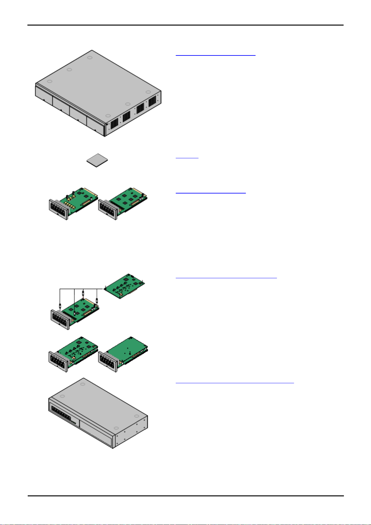
2.3 System Components
· IP Office 500v2 Control Unit
The control unit, holds the main configuration and performs
the routing and switching for telephone calls and data traffic.
The control unit includes LAN ports, slots for additional internal
cards and in some cases integral digital and analog phone
ports.
· SD Card
The IP Office 500v2 control unit uses the Avaya SD flash
memory card which has Essential Edition - PARTNER® Version
software and Embedded Voicemail already installed. Each
Avaya SD card has a unique serial number.
· IP Office 500 Base Cards
The control unit has slots for up to four base cards. These can
be used to add analog and digital extension ports.
· IP Office 500 Digital Station Base Card
· IP Office 500 ATM Combination Card
· IP Office 500v2 ETR6 Base Card
· IP Office 500 Analog Phone Base Card
· IP Office 500 VCM Base Card
· IP Office 500 4-Port Expansion Base Card
· IP Office 500 Trunk Daughter Cards
Some base cards can be fitted with a IP Office 500 daughter
card in order to support various types of trunk connections.
· IP Office 500 Analog Trunk Card
· IP Office 500 T1 Trunk Card
· IP Office 500 PRI Trunk Card
· IP Office 500 SIP Trunk Card
· IP Office 500 Combination Cards
These card are pre-paired base and daughter cards. They
provide 6 digital station ports, 2 analog phone ports and 4
analog trunks.
· IP Office 500 External Expansion Modules
Additional analog and digital extension ports can be added
using an IP Office 500 external expansion module.
· Only one Digital Station 16 or one Phone 16 module may be
used with Essential Edition - PARTNER® Version.
The following are typical components of an Essential Edition - PARTNER® Version system.
PARTNER® Version, Installation and Reference Manual Page 16
- Issue 1a (30 January 2010)IP Office Essential Edition
Page 18
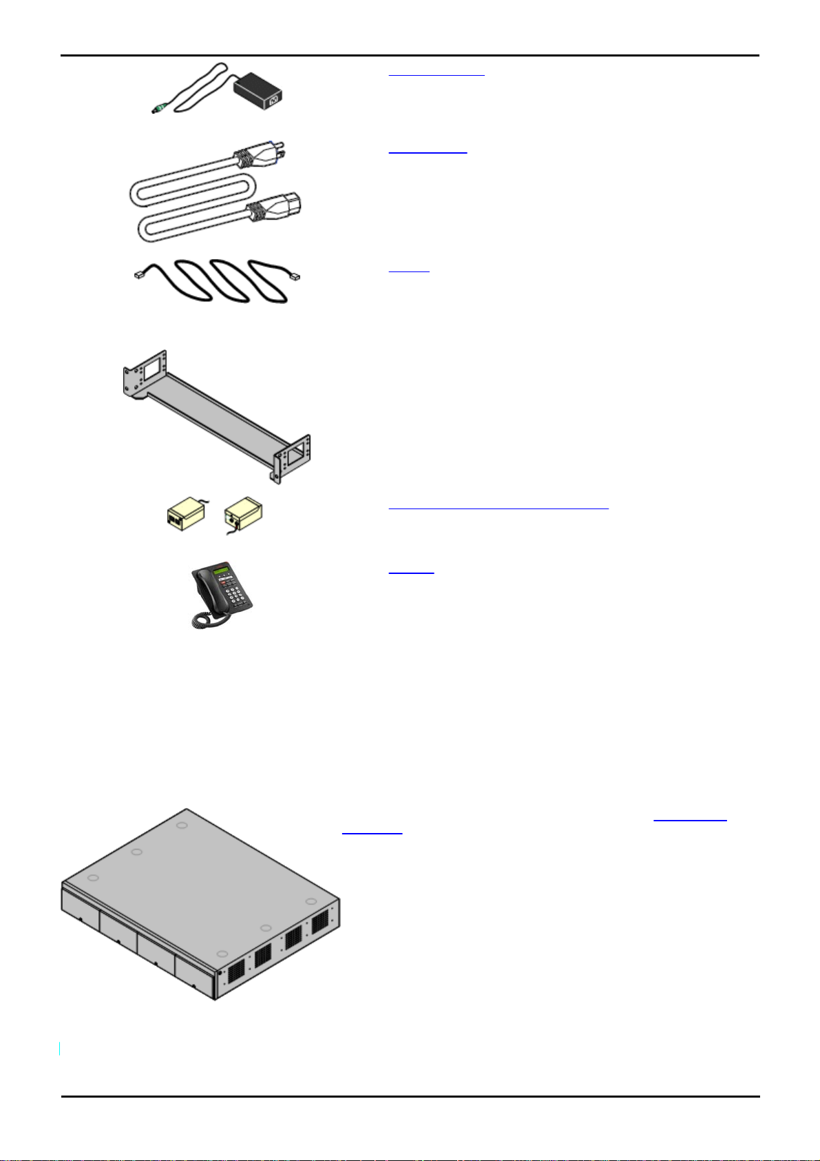
System Overview: System Components
· Power Supplies
The IP Office 500 V2 control unit has an internal power supply
unit. Each external expansion module is supplied with an
external power supply unit. Additional power supply units may
also be required for IP phones and some phone add-ons.
· Power Cords
Depending on the locale, different power cords need to be
ordered for each control unit, external expansion module and
any phones or devices using external power supply units.
· Cables
The Essential Edition - PARTNER® Version is designed
primarily for connection to a structured cabling system using
CAT3 UTP cabling. This approach allows telephone and data
traffic to share the same wiring infrastructure and simplifies
equipment moves.
· Mounting Kits
The IP Office 500v2 control unit can be used free-standing,
with an external expansion module stacked above it. With
optional rack mounting kits, the control unit and external
expansion module can also be rack mounted. Alternatively
with an optional wall mounting kit the control unit can be wall
mounted.
· Surge Protectors and Barrier Boxes
Where the installation includes extensions in other buildings
additional protective equipment is required. This equipment
may also be required in areas where the lightning risk is high.
· Phones
Essential Edition - PARTNER® Version systems support a
variety of Avaya digital and wireless phones plus analog
phones.
The IP Office 500v2 control unit has four front slots for IP Office 500
base cards. It has an internal power supply unit and uses a mandatory
dongle in the form of an SD Card plugged into a rear panel slot. It
includes a 2 port ethernet LAN switch (layer 3 managed) on the rear.
2.4 Control Unit
The base item of the Essential Edition - PARTNER® Version system is the system server or control unit. It stores the
system configuration and controls system operation. Essential Edition - PARTNER® Version uses the IP Office 500v2 R6.0
control unit or above.
A control unit can be customized by adding various internal cards such as trunk cards. external expansion modules can
be also be connected to add additional extension and trunk ports.
The following table summarizes the capacities of the control unit supported by Essential Edition - PARTNER® software.
PARTNER® Version, Installation and Reference Manual Page 17
- Issue 1a (30 January 2010)IP Office Essential Edition
Page 19
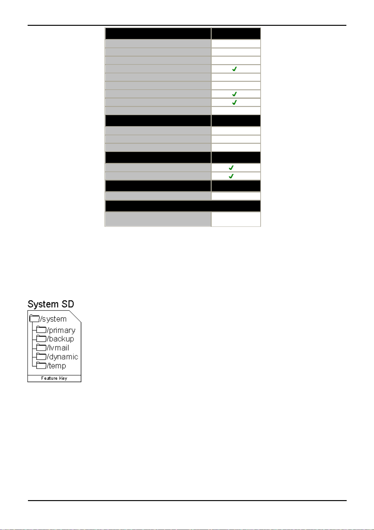
Feature
Provision
Control Unit Digital Station Ports
Up to 30
Control Unit Analog Phone Ports
Up to 26
Control Unit ETR Phone Ports
18
Embedded Voicemail Card
Integral WAN Port
Not used
External Expansion Ports
1
Audio In (MOH) Port
External O/P Switch Port
Conference Parties
10
Maximum Extension Capacity
48
Digital Phones only.
46
Analog Phones only.
42
ETR Phones only.
18
IP500 Trunk Daughter Cards
IP500 Analog trunks
12
IP500 PRI trunk channels
24
VCM Cards
IP500 VCM Cards
2**
Dimensions
Height x Width x Depth
73x445x365mm
2.9"x17.5"x14.4"
** Only supports VCM channels provided by fitting IP500 Combination cards.
2.5 SD Card
The Avaya SD card exercises central control over the Essential Edition - PARTNER® Version system and acts as the
License dongle for the control unit. The SD card is inserted into the System SD slot on the rear of the control unit.
Except during maintenance the System SD slot should contain an Avaya SD card at all times. The files on that card are
used when the system is started and the Feature Key serial number only present on Avaya cards is used for the licensing
of Essential Edition - PARTNER® Version features.
· The SD card stores system files, the system status application (SSA) and a voice mail application providing 2 channels
by default but can be licensed for up to 6 channels total.
· The system SD card is also used to store copies of core software binary files, configuration files and backups.
· Various commands within Manager interface enables the SD card contents to be backed up, restored or copied.
· The control unit has an Optional SD slot as well as the System SD slot. This Optional SD card slot can be used to
store occasional full copies of the System SD card. or as an additional memory card to or from which, files can be
copied. Non-Avaya cards can be used for this as long as they conform to the standard below:
SDHC minimum 4GB FAT32 format (Single partition, SDHC, class2+, FAT32, SPI & SD bus).
o
PARTNER® Version, Installation and Reference Manual Page 18
- Issue 1a (30 January 2010)IP Office Essential Edition
Page 20
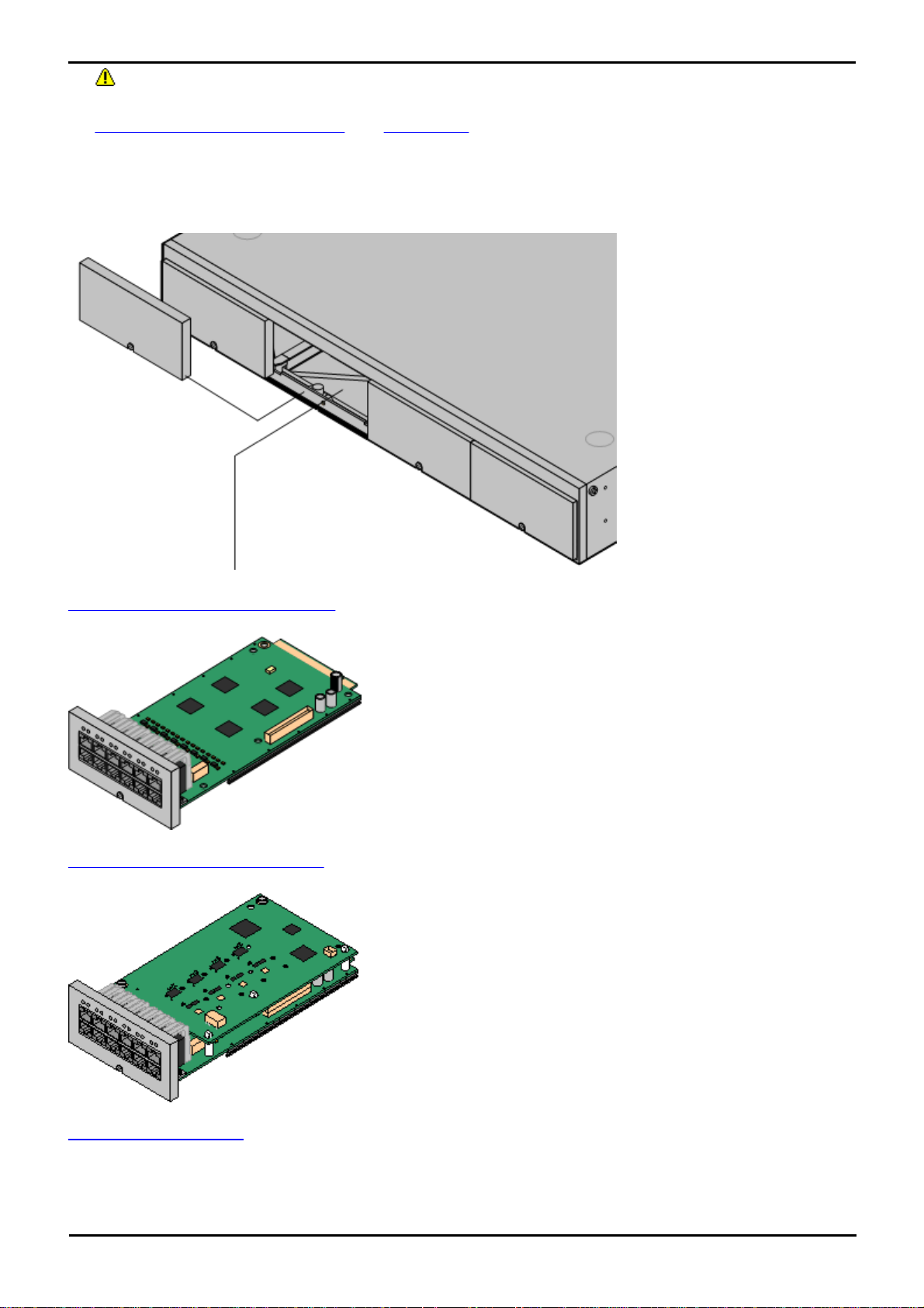
System Overview: SD Card
The IP Office 500v2 control unit
has 4 slots to accomodate base
cards. Each base cards includes
an integral front panel with
ports for cable connections.
The slots are numbered 1 to 4
from left to right. Normally they
can be used in any order,
however if the capacity for a
particular type of card is
exceeded, the card in the
highest slot will be disabled.
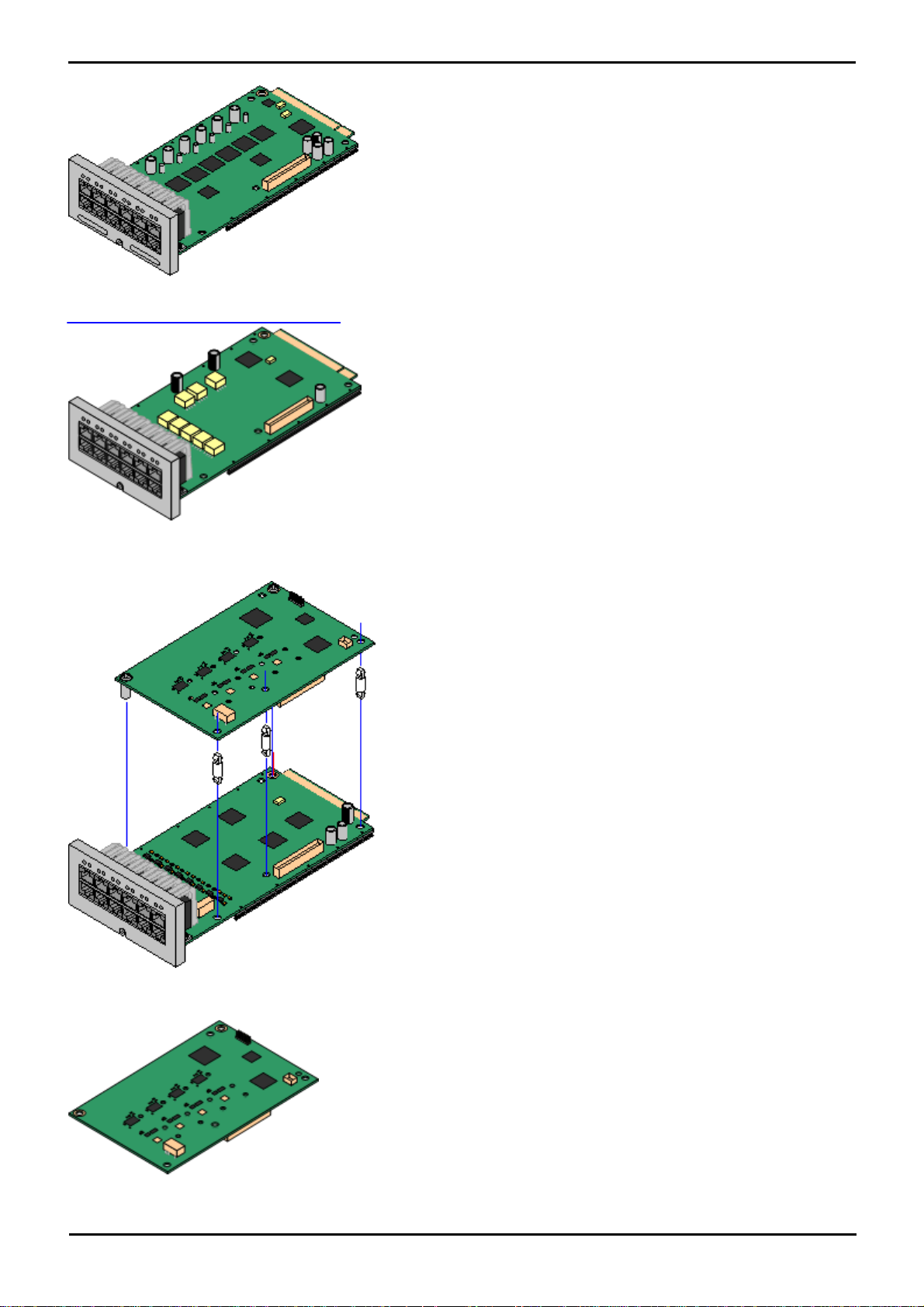
IP Office 500 Analog Phone Base Card
This card has 12 RJ45 ports. The card is available in two variants,
providing 2 or 8 analog extension ports for the connection of analog
phones. The card can be fitted with an IP Office 500 daughter card
which then uses the additional 4 RJ45 ports for connections.
· This card accepts one IP Office 500 daughter card of any type.
· Maximum: 4 per control unit.
· When fitted with an IP Office 500 Analog Trunk daughter card, the
Phone 8 base card supports 1 power failure extension to trunk (loopstart only) connection.
· The analog extension ports do not include a ringing capacitor. Where
this is a requirement, connection should be via a Master socket
containing ringing capacitors.
IP Office 500 ATM Combination Card
This card provides 6 digital station ports (1-6), 2 analog extension
ports (7-8) and 4 analog trunk ports (9-12). The card also includes 10
VCM channels.
· This card has a pre-installed IP Office 500 ATM daughter card.
· Maximum: 2 combination cards per control unit.
· During power failure port 8 is connected to port 12.
IP Office ETR6 Base Card
This card is only supported in an IP500 V2 control unit running in
PARTNER® Version mode. It provides 6 ETR ports for connection of
ETR phones. 2 Analog extension ports are also provided for emergency
use only with an analog trunk card.
SD Card Removal
SD cards should never be removed while being used. Though the SD card slot LEDs indicate when data is being
written to an SD card, lack of flashing LED is not a sufficient safeguard. The IP Office Manager provides methods to
shutdown and restart an individual card or to shutdown the Essential Edition - PARTNER® Version system in order to
allow removal of an SD card. If the System SD card is removed, licensed features will continue operating for up to 2
hours.
2.6 Base Cards
PARTNER® Version, Installation and Reference Manual Page 19
- Issue 1a (30 January 2010)IP Office Essential Edition
Page 21
· The card can be fitted with an IP500 trunk daughter card which uses
the base card ports for trunk connection.
· Maximum: 3 per control unit.
· The analog phone ports do not include a ringing capacitor. Where
this is a requirement, connection should be via a Master socket
containing ringing capacitors.
· If fitted with an IP Office 500 Analog Trunk daughter card, during
power failure phone ports 7 and 8 are connected to analog trunk
port 12. However during normal operation analog phone ports 7 and
8 are not useable.
IP500 Digital Station Base Card
This card provides 8 DS (digital station) ports for the connection of
Avaya digital phones other than IP phones.
· The card can be fitted with an IP Office 500 trunk daughter card
which uses the base card ports for trunk connection.
· Maximum: 3 per control unit.
· 4400 Series phones (4406D, 4412D and 4424D) are not supported
on this card. They are supported on an external expansion module.
IP Office 500 daughter trunk cards can be fitted to IP Office 500
base cards to provide support for trunk. The daughter card uses the
physical ports provided on the front panel of the base card for cable
connection.
The addition of an IP Office 500 daughter card is supported on any
IP Office 500 base card except the IP Office 500 Legacy Card Carrier
base card.
For those base card that support daughter cards, there are no
restrictions on the combination of card types. However in systems
with both analog phone base cards and analog trunk daughter cards,
combining the two types is recommended as it then provides analog
power failure support for one trunk/extension.
Each daughter card is supplied two pre-fitted metal pillars and 3
plastic pillars. Two screws and washers for final attachment of the
metal pillars to the base card are also included.
IP Office 500 Analog Trunk Daughter Card
This card can be added to IP Office 500 base cards. It enables that
base card to then also support four analog loop-start trunks.
· When fitted to an IP Office 500 Analog Phone 8 base card, the
combination supports 1 power failure extension to trunk
(loop-start only) connection.
· Maximum: 2 per IP Office 500v2 control unit.
2.7 Trunk Cards
PARTNER® Version, Installation and Reference Manual Page 20
- Issue 1a (30 January 2010)IP Office Essential Edition
Page 22
System Overview: Trunk Cards
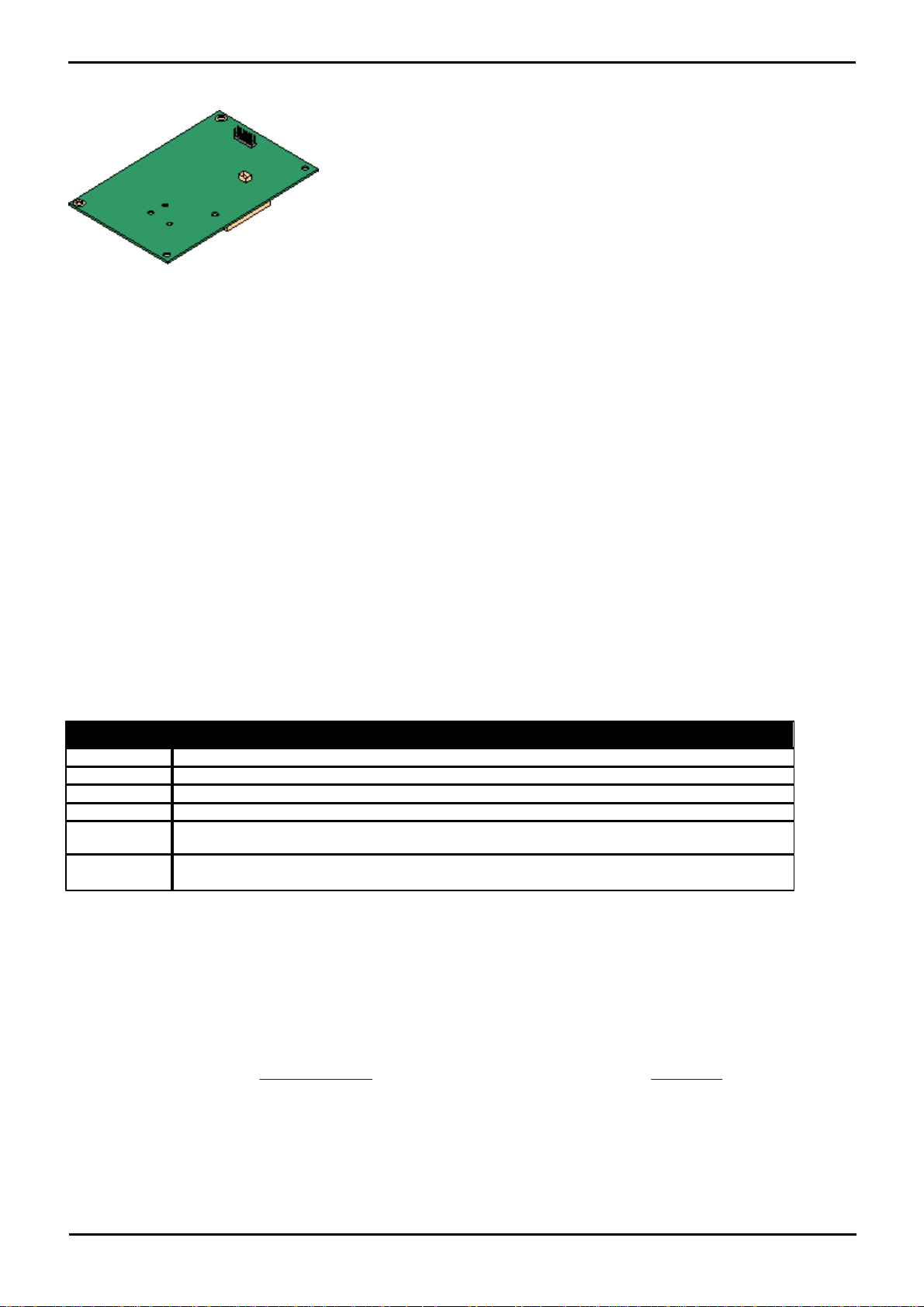
IP Office 500 PRI-U Trunk Daughter Card
This card can be added to an IP Office 500 base card. The card is a
universal card that can be configured in software for E1 PRI, T1
robbed bit, T1 PRI or E1R2. The card is available in single and dual
port variants.
· Maximum: 4 per IP Office 500v2 control unit.
· The IP Office 500 PRI-U card supports E1, T1 and E1-R2 PRI
modes. The Essential Edition - PARTNER® Version system
supports 8 unlicensed B-channels on each IP Office 500 PRI-U port
fitted. Additional B-channels, up to the capacity of ports installed
and PRI mode selected require IP Office 500 Universal PRI
(Additional Channels) licenses added to the configuration.
These additional channels consume the licenses based on which
additional channels are configured as in-service from port 9 of slot
1 upwards. D-channels are not affected by licensing.
RFRFCC
Description
2833 [7]
RTP Payload for DTMF digits, telephony tones and telephony signals.
3261 [8]
SIP Session Initiation Protocol.
3264 [11]
An Offer/Answer Model with Session Description Protocol (SDP).
3323 [14]
A Privacy Mechanism for SIP
3489 [18]
STUN - Simple Traversal of User Data gram Protocol (UDP) Through Network Address
Translators (NATs).
3824 [24]
Using E.164 Numbers with the Session Initiation Protocol (SIP).
E.164 is the ITU-T recommendation for international public telecommunication numbering plans.
2.8 SIP Cards
Essential Edition - PARTNER® Version supports both SIP trunks and SIP extensions. Because there is a wide variety of
SIP devices and interpretations of standards, Avaya cannot give any guarantees of support for all SIP extension devices
and features.
SIP Trunk Providers
Essential Edition - PARTNER® Version SIP trunks have been successfully tested with the following ITSP SIP providers.
This table of providers is a statement of fact and not any form of recommendation from Avaya, nor does it exclude other
service providers. Any details of the expected operation and service should be confirmed in writing with the individual
service provider.
The SIP Gate service does not support RFC2833 for the sending of DTMF tones. SIP Gate uses the alternate SIP INFO
method which is not supported by Essential Edition - PARTNER® Version.
Essential Edition - PARTNER® Version supports SIP trunks using UDP or TCP. For UDP SIP, STUN is supported for NAT
Firewall traversal. Otherwise use of a service provider supporting Session Border Control (SBC) is required. TURN,
sometimes used for TCP SIP traversal of NAT firewalls, is not supported.
The Essential Edition - PARTNER® Version implementation of SIP conforms to the following SIP RFCs.
2.9 External Expansion Module
This module can be used to add additional ports to a Essential Edition - PARTNER® Version system. Only one external
expansion unit is supported
· The external expansion module is supplied with a blue 1 meter (3'3'') expansion interconnect cable. This cable
must be used when connecting to expansion ports on the rear of a control unit.
Each module uses an external power supply unit supplied with the module. A locale specific power cord for the PSU must
be ordered separately.
PARTNER® Version, Installation and Reference Manual Page 21
- Issue 1a (30 January 2010)IP Office Essential Edition
Page 23
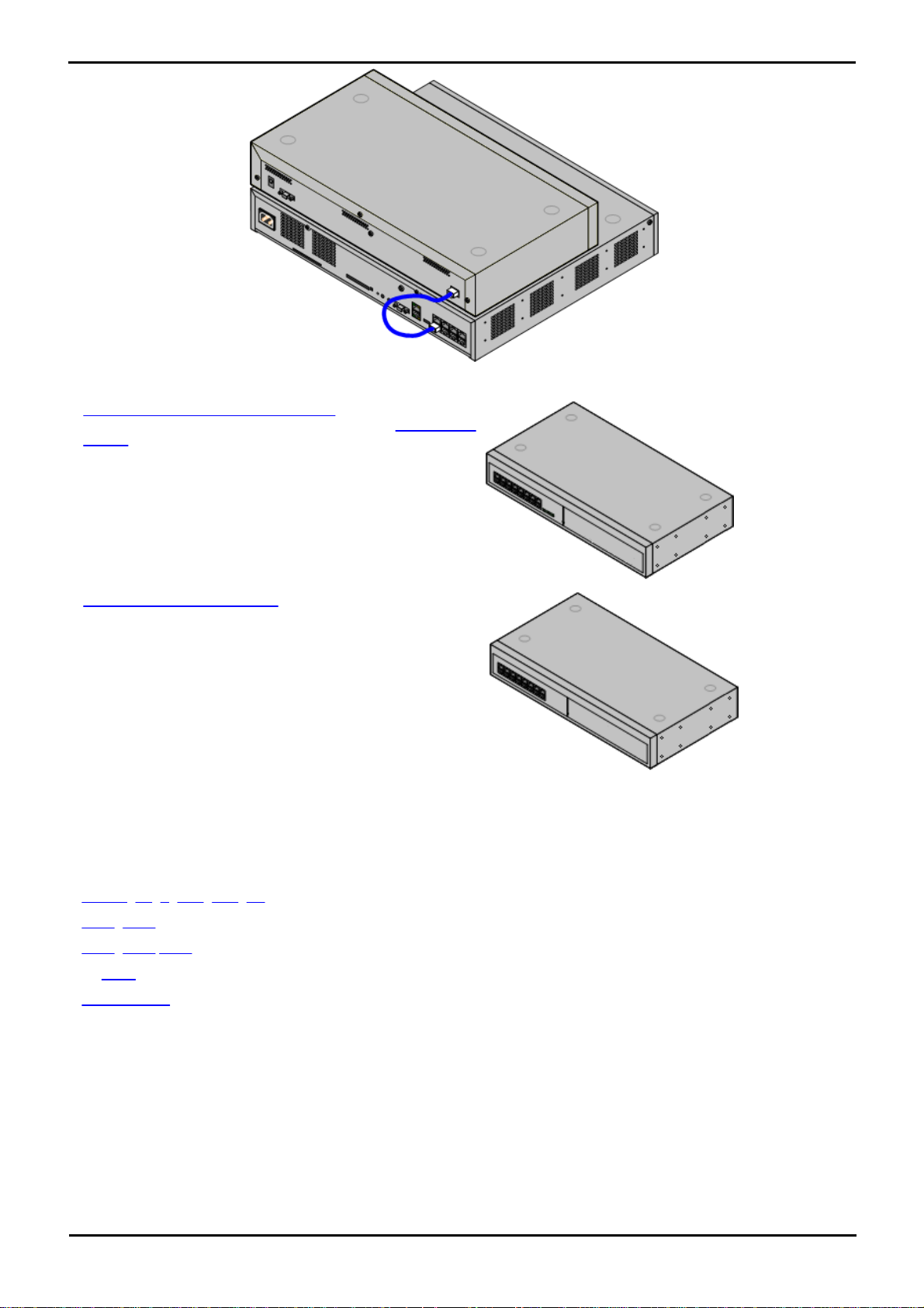
· IP Office 500 Digital Station Module
Provides an additional 16 DS ports for supported Avaya digital
phones.
· IP Office 500 Phone Module
Provides an additional 16 PHONE ports for analog phones.
2.10 Supported Phones
Essential Edition - PARTNER® Version supports the following phones and phone add-ons. Availability may be subject to
local restrictions.
· ETR 34, 18, 6, 34D, 18D, 6D,
· 3910, 3920
· 1403, 1408 1416
· All POTS telephones
· BM32 Buttons
· Digital station connects to the Essential Edition - PARTNER® Version via a DS port.
PARTNER® Version, Installation and Reference Manual Page 22
- Issue 1a (30 January 2010)IP Office Essential Edition
Page 24

System Overview: Dial Plan
0
Dial Physical Extn [1st Port]
10-57
Station extensions
610-657
Directed call pickup
661-664
Group call pickup (pickup groups 1-4)
6801-6864
Directed line pickup
70
Loudspeaker Page
71-74
Group calling (calling groups 1-4)
76
Modem (RAS port)
771-776
Hunt group (hunt groups 1-6)
777
Voicemail Collect
778
Remote Voicemail access
7801
Auto Attendant access
7811
Record Auto Attendant Morning Greeting
7821
Record Auto Attendant Afternoon Greeting
7831
Record Auto Attendant Evening Greeting
7841
Record Auto Attendant Menu Greeting
7851
Record Auto Attendant Out of Hours Greeting
801-864
Idle line pickup
9
Dial access to Idle Line Preference
*
Voice signal (Intercom only)
*70
Loudspeaker Page + Page Calling Group 1
77901 77999
Mobility Features
2.11 Dial Plan
Essential Edition - PARTNER® Version has a fixed 2-digit dial plan. The extensions are numbered from 10 to 57 which
constitutes a 2 digit dial plan. Short codes are used to access the different features:
· 6 – Call Pickup
· 66 – Group Call Pickup
· 68 – Directed Line Pickup
· 7 – Group access
· 8 – Idle Line Pickup
The dial plan below identifies the valid digit sequences that can be dialled from Essential Edition - PARTNER® Version:
2.12 Core Software & BIN Files
Each IP Office 500v2 control unit and expansion module contains and runs its own part of the IP Office core software.
These parts take the form of .bin files (binary files).
The Essential Edition - PARTNER® Version control unit is supplied with a base level of IP Office software that acts as a
software loader for upgrading the unit to the required software level. This software loader supports the LAN connection
necessary for local PC to IP Office upgrade. See IP Office Manager Essential Edition - PARTNER® Version Administrator
User Guide.
The .bin files for each IP Office software level are included on the Essential Edition - PARTNER® Version SD Card for that
software level. They are installed from that SD as part of the Essential Edition - PARTNER® Version Manager application.
Manager can then be used to upgrade the .bin files loaded in the modules within a system.
Updated sets of software and bin files may also be made available through the Avaya support web site. See Web Sites.
· Software Level
The IP Office core software level is expressed in the form X.Y(Z), for example 2.1(27), where X is the major software
level, Y is the minor level and Z is the build number.
The following rules apply to the core software level used by modules within an Essential Edition - PARTNER® Version
system and between linked IP Office systems.
· All modules within an Essential Edition - PARTNER® Version should run the same level of core software. Doing
otherwise will lead to incorrect operation of the system.
PARTNER® Version, Installation and Reference Manual Page 23
- Issue 1a (30 January 2010)IP Office Essential Edition
Page 25
Upgrading
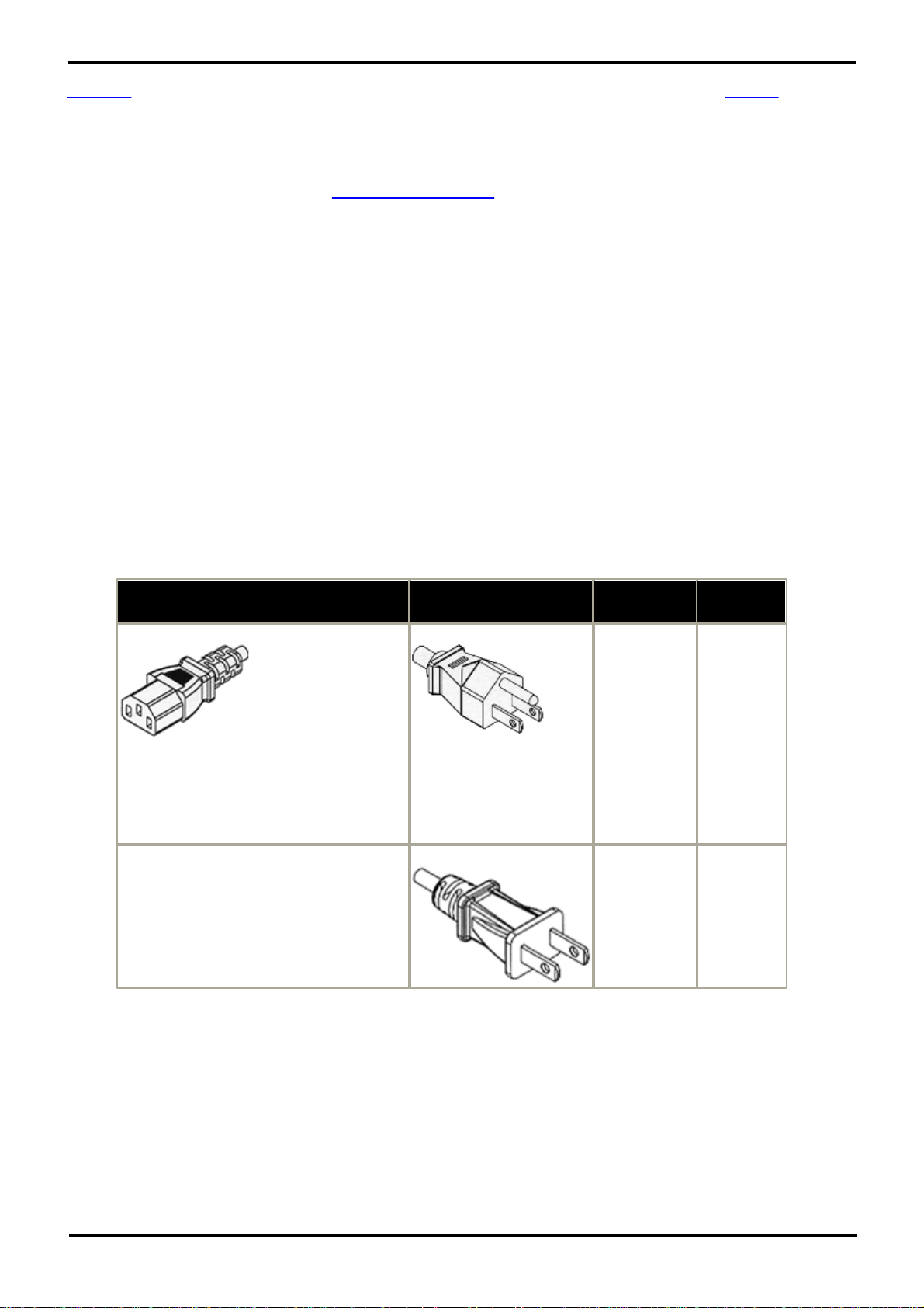
Power Cord Type
Power Outlet Plug Type
Locales
Part
number
Earthed Power Cords (IEC60320 C13)
Control Units
· IP Office 500.
IP Office 500 External Expansion Modules
· Digital Station 16.
· Phone 16.
NEMA5-15P / CS22.2 No.42
North, Central
and South
America.
700289770
NEMA1-15
North, Central
and South
America.
700213390
Upgrading is performed using the Upgrade Wizard tool within the Essential Edition - PARTNER® Version Manager
application (File | Advanced | Upgrade). It displays the systems it can detect, their existing software level and the
levels it has available.
· Check IP Office Technical Bulletins
Whenever upgrading check the latest IP Office Technical Bulletins for the various IP Office software releases involved
before proceeding. These may contain information relating to changes that occurred after this document was
completed. Bulletins are available from http://support.avaya.com.
· Multi-Stage Upgrades
The upgrade path may require several intermediate upgrades. Skipping an intermediate level may lead to incorrect
system operation and configuration corruption. Multi-stage upgrades are only necessary for control units. External
expansion modules can be upgraded directly between any two levels supported by the module.
2.13 Power Supplies
Each control unit and expansion module has an internal power supply unit that requires a switched power outlet socket
rated at 110-240V ac, 50-60Hz. Connection from that power outlet socket requires an appropriate locale specific power
cord which is not supplied with the unit and must be ordered separately.
External expansion modules are supplied with an external power supply unit (PSU). These external power supply units
include an integral 1.5 meter lead for connection to the control unit or expansion module. A power cord for connection
from the PSU to the power outlet is not included as this varies by locale. The appropriate power cord must be ordered
separately or sourced locally.
Power cords must not be attached to the building surface or run through walls, ceilings, floors and similar openings.
Installation measures must be taken to prevent physical damage to the power supply cord, including proper routing of
the power supply cord and provision of a socket outlet near the fixed equipment or positioning of the equipment near a
socket outlet.
For locales not detailed below an appropriate power cord must be obtained locally.
2.13.1 Power Supply Backup
The use of an Uninterrupted Power Supply (UPS) with any telephone system is recommended. Even at sites that rarely
lose electrical power, that power may occasionally have to be switched off for maintenance of other equipment. In
addition, most UPSs also provide an element of power conditioning, reducing spikes and surges.
The capacity of UPS systems and the total equipment load the UPS is expected to support are usually quoted in VA.
Where equipment load is quoted in Watts, multiply by 1.4 to get the VA load.
The calculation of how much UPS capacity is required depends on several choices.
PARTNER® Version, Installation and Reference Manual Page 24
- Issue 1a (30 January 2010)IP Office Essential Edition
Page 26
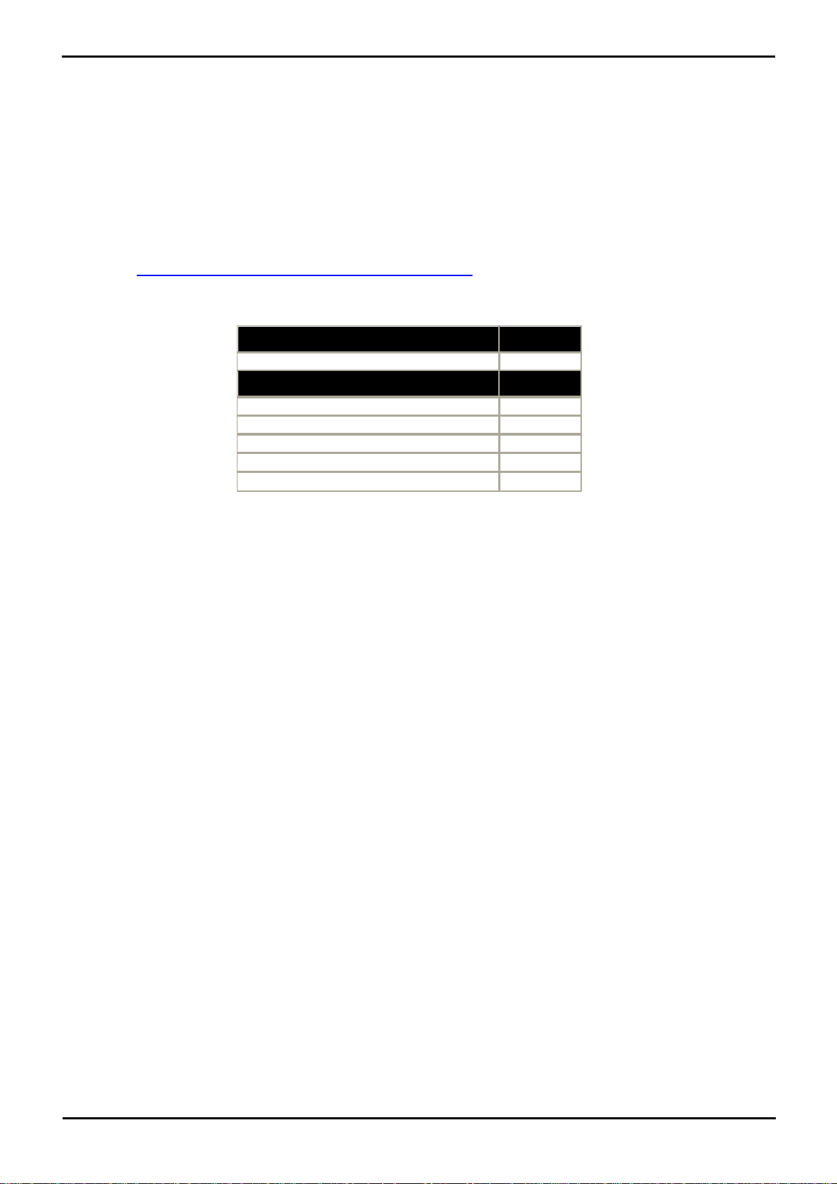
System Overview: Power Supplies
Typical IP Office System
VA
IP Office System
230
Individual Equipment
VA
Phone 8 Module
17
Typical Server PC
600
Typical Desktop PC
400
Mid Span PSU - 6 ports
150
Mid Span PSU - 12/24 ports
300
· What equipment to place on the UPS?
Remember to include server PCs such as the voicemail. It is recommended that the total load on a new UPS is never
greater than 75% capacity, thus allowing for future equipment.
· How many minutes of UPS support is required?
Actual UPS runtime is variable, it depends on what percentage of the UPSs capacity the total equipment load
represents. For example, a 1000VA capacity UPS may only support a 1000VA (100%) load for 5 minutes. This
relationship is not linear, the same UPS would support a 500VA (50%) load for 16 minutes. Therefore the lower the
percentage of capacity used, the increasingly longer the UPS runtime, typically up to 8 hours maximum. Remember
also that for most UPSs the ratio of discharge to full recharge time is 1:10.
· How many output sockets does the UPS provide?
Multiple UPS units may be required to ensure that every item of supported equipment has its own supply socket.
The web site http://powerquality.eaton.com/AVAYA/default.asp?cx=101 provides a calculator into which you can enter
the equipment you want supported on a UPS. It will then display various UPS options. The site uses VA values for typical
IP Office systems. However, if more specific values are required for a particular system, the table below can be used to
enter values.
PARTNER® Version, Installation and Reference Manual Page 25
- Issue 1a (30 January 2010)IP Office Essential Edition
Page 27

PARTNER® Version, Installation and Reference Manual Page 26
- Issue 1a (30 January 2010)IP Office Essential Edition
Page 28

Chapter 3.
Installing PARTNER®
PARTNER® Version, Installation and Reference Manual Page 27
- Issue 1a (30 January 2010)IP Office Essential Edition
Page 29
3. Installing PARTNER®
This section is intended to assist with the installation of the core components of an Essential Edition - PARTNER® Version
telephone system. It describes those components and factors that should be considered for an installation.
· The Essential Edition - PARTNER® Version is a converged voice and data communications system. It should therefore
only be installed by persons with telephony and IP data network experience.
· Installers must be trained on IP Office systems. Through its Avaya University (http://www.avaya-learning.com), Avaya
provides a range of training courses including specific IP Office Essential Edition - PARTNER® Version implementation
and installation training. It also provides certification schemes for installers to achieve various levels of IP Office
accreditation. See Training.
· It is the installer’s responsibility to ensure that all installation work is done in accordance with local and national
regulations and requirements. It is also their responsibility to accurately establish the customer’s requirements before
installation and to ensure that the installation meets those requirements.
· You should read and understand this documentation before installation. You should also obtain and read the Avaya
Technical Bulletins relevant to recent Essential Edition - PARTNER® Version software and hardware releases to ensure
that you are familiar with any changes to the equipment and software.
Quick installation instructions are contained in a separate document.
3.1 IP Office Manager
Installation and maintenance of Essential Edition - PARTNER® Version can be performed through telephone system TUI
commands described in the Avaya IP Office Essential Edition - PARTNER® Version Admin Guide. However the Manager
application provides a comprehensive and easy to use interface for installation and maintenance.
The IP Office Essential Edition - PARTNER® Version Admin Tool (Manager) is an application for viewing and editing an IP
Office system configuration. It is a tool meant primarily for system installers and maintainers. Manager runs on a
Windows PC and connects to the Essential Edition - PARTNER® Version control unit via the Ethernet LAN connection.
Office manager can be used to prepare user lists, permissions, group memberships and other administration tasks on the
telephone system. Manager has its own Administrator User Manual containing comprehensive user instructions.
· CAUTION - Password Change Required
New IP Office systems use default security settings. These settings must be changed to make the system secure.
As a minimum, you should change the default Remote/Administrator Password. Failure to do so will render
the Essential Edition - PARTNER® Version system potentially insecure.
· IMPORTANT
Manager is an off-line editor. It receives a copy of the current configuration settings for the Essential Edition PARTNER® Version system, from the control unit SD Card. Changes may be made to that copy and it is then sent
back to the SD Card for those changes to become active. This means that changes to the active configuration in
the system that occur between Manager receiving and sending back the copy may be overwritten. For example
this may affect changes made by users through their phone or voicemail mailbox after the copy of the
configuration is received by Manager.
Manager is part of the IP Office Admin suite of programs. It is important to note that the software level of IP Office
Manager application is 2 higher than the software level of the IP Office system core software with which it is released. For
example IP Office Manager 8.0 is released with IP Office 6.0 core software.
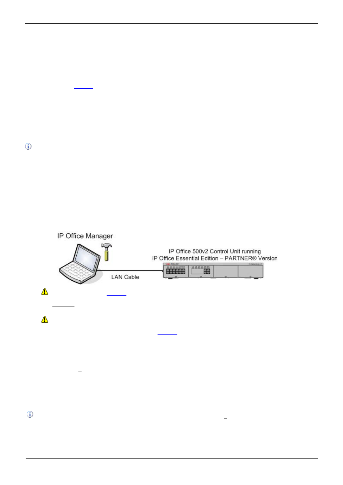
When IP Office Manager is used with Essential Edition - PARTNER® Version, the PC running Manager is connected directly
to the IP Office control unit being installed or updated. IP Office Manager detects that a PARTNER® Version is present
and automatically starts in its Simplified mode designed to manage Essential Edition - PARTNER® Version.
It is important to note that the software level of IP Office Manager application is 2 higher than the software level of
the IP Office system core software with which it is released. For example IP Office Manager 8.0 was released with IP
Office 6.0 core software.
PARTNER® Version, Installation and Reference Manual Page 28
- Issue 1a (30 January 2010)IP Office Essential Edition
Page 30

Installing PARTNER®: Getting Started
Objective - To check that the correct equipment has been supplied and
that no damage has occurred during transit.
Use the following procedure when unpacking any equipment supplied by
Avaya or an Avaya reseller or distributor.
Information Required
· Equipment Checklist.
Draw up an installation checklist of the parts and equipment
expected.
3.2 Getting Started
This section describes tasks that must be planned and executed before commencing installation of Essential Edition PARTNER® Version.
3.2.1 Unpacking
Procedure
· Check for Package Damage.
Before unpacking any equipment, check for any signs of damage that may have occurred during transit. If any
damage exists bring it to the attention of the carrier.
· Check the Correct Parts Have Been Delivered.
Check all cartons against the packing slip and ensure that you have the correct items. Report any errors or
omissions to the equipment supplier.
· Retain All Packaging and Documentation.
While unpacking the equipment, retain all the packaging material. Fault returns are accepted only if repackaged in
the original packaging. If performing a staged installation, the original packaging will also assist when repacking
equipment to be moved to the final install site.
· Ensure that Anti-Static Protection Measures are Observed.
Ensure that anti-static protection measures are observed at all times when handling equipment with exposed
electrical circuit boards.
· Check All Parts.
Visually inspect each item and check that all the necessary documentation and accessory items have been
included. Report any errors or omissions to the dealer who supplied the equipment.
· Check All Documentation.
Ensure that you read and retain any documentation included with the equipment.
3.2.2 Environmental Requirements
Before you begin the physical installation of the system, you must check that all environmental factors are within the
acceptable ranges. The planned location must meet the following requirements. If installing into a rack system, these are
requirements for within the rack:
· Temperature: 0°C to 40°C / 32°F to 104°F.
· Humidity: 10% to 95% non-condensing.
· Check there are no flammable materials in the area.
· Check there is no possibility of flooding.
· Check that no other machinery or equipment needs to be moved first.
· Check that it is not an excessively dusty atmosphere.
· Check that the area is unlikely to suffer rapid changes in temperature and humidity.
· Check for the proximity of strong magnetic fields, sources of radio frequency and other electrical interference.
· Check there are no corrosive chemicals or gasses.
· Check there is no excessive vibration or potential of excessive vibration, especially of any mounting surface.
· Check that where telephones are installed in another building, that the appropriate protectors and protective
grounds are fitted (see Out of Building Telephone Installation).
· Check there is suitable lighting for installation, system programming and future maintenance.
· Check that there is sufficient working space for installation and future maintenance.
· Ensure that likely activities near the system will not cause any problems, e.g. access to and maintenance of any
other equipment in the area.
PARTNER® Version, Installation and Reference Manual Page 29
- Issue 1a (30 January 2010)IP Office Essential Edition
Page 31

· Where ventilation holes are present on any of the Essential Edition - PARTNER® Version units, those holes should
Ensure that you have read this manual in full before starting installation. Also include the
installation documentation for any other equipment and applications being installed as part
of the IP Office system.
not be covered or blocked.
· The surface must be flat horizontal for free-standing or rack mounted installations.
Wall Mounting
In additional to the requirements above, the following are applicable to Essential Edition - PARTNER® Version units that
support wall mounting.
1. Units must only be mounted onto permanent wall surfaces.
2. The surface must be vertical and flat.
3. Orientation of the unit must be as shown in the section on IP Office 500 Wall Mounting.
4. The appropriate Avaya wall mounting kits must be used.
IMPORTANT SAFETY INSTRUCTIONS
When using your telephone equipment, basic safety precautions should always be followed to reduce the risk of fire,
electric shock and injury to persons, including the following:
1. Do not use this product near water, for example, near a bath tub, wash bowl, kitchen sink or laundry tub, in a wet
basement or near a swimming pool.
2. Avoid using a telephone (other than a cordless type) during an electrical storm. There may be a remote risk of electric
shock from lightning.
3. Do not use the telephone to report a gas leak in the vicinity of the leak.
4. Use only the power cord and batteries indicated in this manual. Do not dispose of batteries in a fire. They may
explode. Check with local codes for possible special disposal instructions.
3.2.3 Read the Documentation
· IP Office Technical Bulletins
Ensure that you have obtained and read the IP Office Technical Bulletin relating to the IP Office software release which
you intend to install on the Essential Edition - PARTNER® Version. This bulletin will contain important information that
may not have been included in this manual. IP Office Technical Bulletins are available from the web sites listed below.
Other IP Office Installation Manuals
The following components of IP Office are outside the range of a basic IP Office installation. They are covered by separate
installation and configuration documentation. If those components are to be part of the Essential Edition - PARTNER®
Version system installation, that documentation should be obtained, read and understood prior to the installation.
Information Web Sites
IP Office documentation is available from the following web sites.
· Avaya Support - http://support.avaya.com
Contains documentation and other support materials for Avaya products including IP Office. Copies of the IP Office
CD images are available from this site and updated core software .bin files.
· Avaya IP Office Knowledge Base - http://marketingtools.avaya.com/knowledgebase
Access to an on-line regularly updated version of the IP Office Knowledge Base. Currently this link is only available
to Avaya Business Partners while running an ARA account (Avaya Remote Access) connection.
3.2.4 Space Requirements
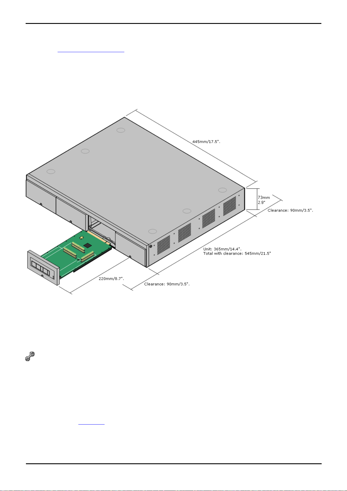
IP Office 500v2 control unit and modules are designed to be installed either in a free-standing stack or into a 19" rack
system. Rack installation requires a rack mounting kit for each control unit and expansion module.
Cable Clearance
Clearance must be provided at the front and rear of all modules for cable access, connections and insertion/removal of
the SD card.
PARTNER® Version, Installation and Reference Manual Page 30
- Issue 1a (30 January 2010)IP Office Essential Edition
Page 32
Installing PARTNER®: Getting Started
· Allow a minimum clearance of 90mm (3.5 inches).
· Additional Clearance
Care should be taken to ensure that the positioning of the modules does not interrupt air flow and other factors that
may affect environmental requirements. This is especially important on IP Office 500 control units which have
ventilation slots at the side.
· Cable Access
Power cords must not be attached to the building surface or run through walls, ceilings, floors and similar openings.
Installation measures must be taken to prevent physical damage to the power supply cord, including proper routing of
the power supply cord and provision of a socket outlet near the fixed equipment or positioning of the equipment near a
socket outlet.
When wall mounted, a clearance of 500mm is required on all sides. The ventilation slots on the rear and sides should not
be covered or blocked.
3.2.5 Tools and Parts Required
This section outlines the tools and miscellaneous parts likely to be required during the installation and setup of an
Essential Edition - PARTNER® Version system. Other tools may also be required.
Tools Required
1. Pozidrive No. 1 screwdriver for removal of module covers.
2. Cutter for cable ties.
3. Pozidrive No. 4 screwdriver.
4. Flat blade screwdriver, medium size
5. Wrist-strap for anti-static grounding or similar.
6. PC running Windows XP/2003.
During the Staging Installation later in this manual, we recommend that you use a Laptop PC with IP Office Manager
Essential Edition - PARTNER® Version installed using a directly connected LAN cable. This will enable you to make any
changes to the basic configuration, system configuration, and set up user lists.
7. Indelible marker for cable labeling.
PARTNER® Version, Installation and Reference Manual Page 31
- Issue 1a (30 January 2010)IP Office Essential Edition
Page 33
Parts Required
Cable
Description
Part
number
Standa
rd
Length
Maximu
m Length
9-Way DTE Cable
Connects to control unit RS232 DTE port.
9-Way D-type plug to 9-way D-type
socket.
–
2m/6'6''
.
2m/6'6''.
Structured Cabling DS Line Cable
Connects from RJ45 sockets to RJ11
socketed DS and analog phones.
7000478
71
4m/13'2
''.
See table
below.
PRI Trunk Cable
Connects PRI trunk ports to the line
providers network termination point. RJ45
to RJ45. Red.
7002134
40
3m/9'10
''.
–
1. Cable ties.
2. Cabling labels.
3. Technical Bulletins
Each Essential Edition - PARTNER® Version software release is normally accompanied by a Technical Bulletin detailing
special installation requirements, known issues, etc. Various software releases and their associated Technical Bulletins
can also be obtained from http://support.avaya.com.
3.2.6 Cabling and Cables
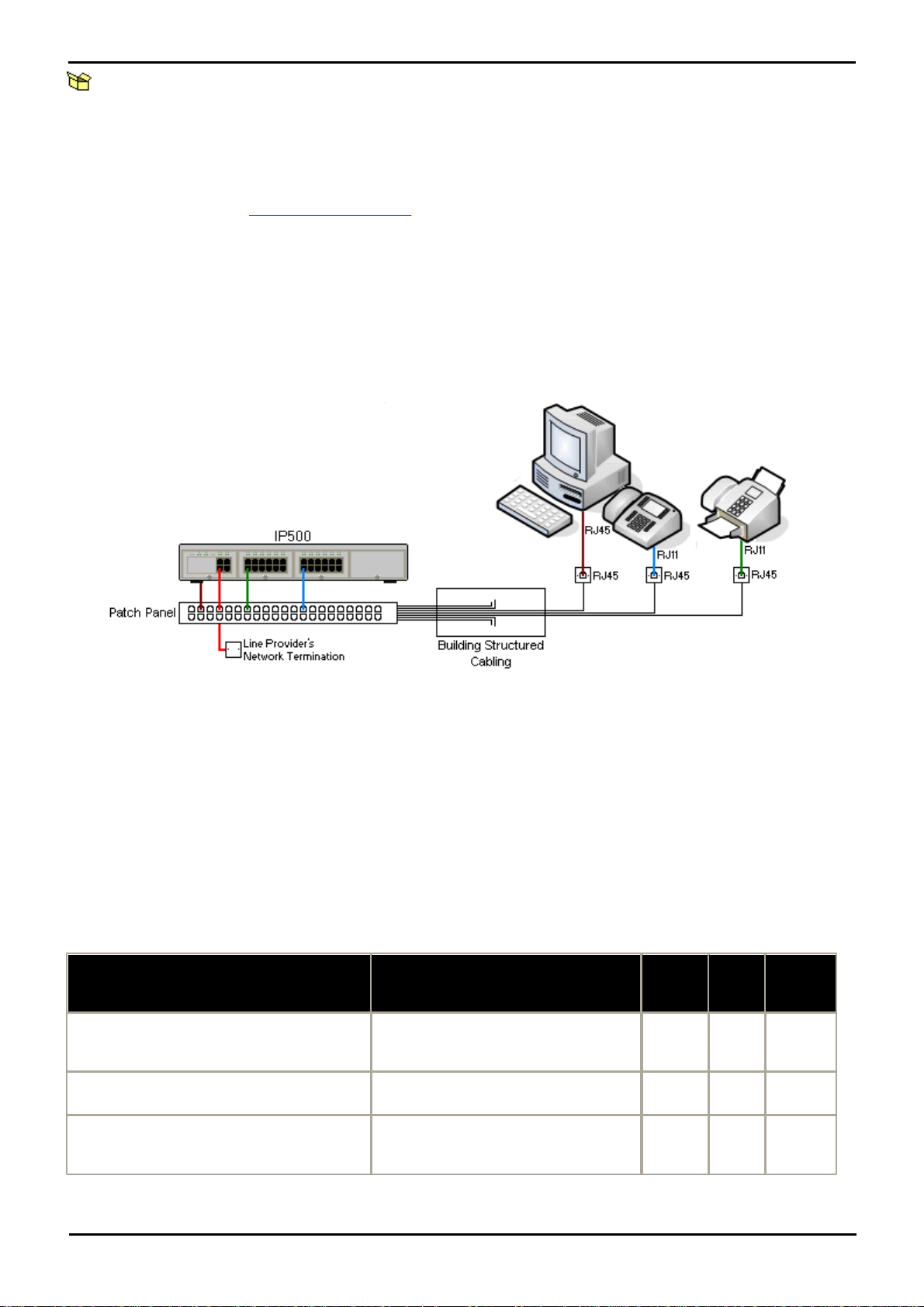
The Essential Edition - PARTNER® Version system is designed primarily for use within an RJ45 structured cabling system
using CAT3 unshielded twisted-pair (UTP) cabling and RJ45 sockets.
A structured cabling system is one where cables are run from a central RJ45 patch panel in the communications/data
room to individual RJ45 sockets at user's desk. All wires in each cable between the patch panel and the desk socket are
connected straight through. This arrangement allows devices connected at the patch panel to be swapped to match the
type of device that needs to be connected at the user socket. For example, making one user socket a phone port and
another user socket a computer LAN port, without requiring any rewiring of the cables in between.
· Traditional IDC Punchdown Wiring Installations
Where necessary, the far end RJ45 plug can be stripped from IP Office cables and wired into traditional wiring systems
using punch-block connectors. This type of installation should be performed by an experienced wiring technician.
· Trunk Connections
The majority of IP Office trunk ports use RJ45 connectors for acceptance of an RJ45-to-RJ45 cable. However,
connection at the line providers end may require use of a different plug type in order to match the line providers
equipment.
· RJ11 Phone Connectors
Many phones use RJ11 sockets and are supplied with RJ11-to-RJ11 cables. RJ11 plugs can be inserted into RJ45
sockets and in many case the connection will work. However this is not recommended or supported as the connection
lock is not truly positive and may become disconnected. An RJ45-to-RJ11 cable is available for these connections.
Standard IP Office Cables
The following are Avaya standard cables available for use with IP Office systems. The maximum length is applicable if the
standard Avaya cable is replaced with an alternative cable.
PARTNER® Version, Installation and Reference Manual Page 32
- Issue 1a (30 January 2010)IP Office Essential Edition
Page 34
Installing PARTNER®: Getting Started
Expansion Interconnect Cable
Connects the control unit to expansion
modules (except WAN3 modules). RJ45 to
RJ45. Blue.
7002134
57
1m/3'3''
.
1m/3'3''.
LAN Cable
Connects from IP Office LAN ports to IP
devices. RJ45 to RJ45. Grey.
7002134
81
3m/9'10
''.
100m/328
'.
Telephone
Unshielded Twisted-Pair (UTP) - 50nf/Km
CW1308
AWG22
(0.65mm)
AWG24
(0.5mm)
AWG26
(0.4mm)
1400 Series
1000m/3280'.
1000m/3280'.
400m/1310'.
400m/1310'.
T3 Series (Upn)
1000m/3280'.
1000m/3280'.
400m/1310'.
–
Analog Phones
1000m/3280'.
1000m/ 3280'.
400m/1640'.
800m/2620'.
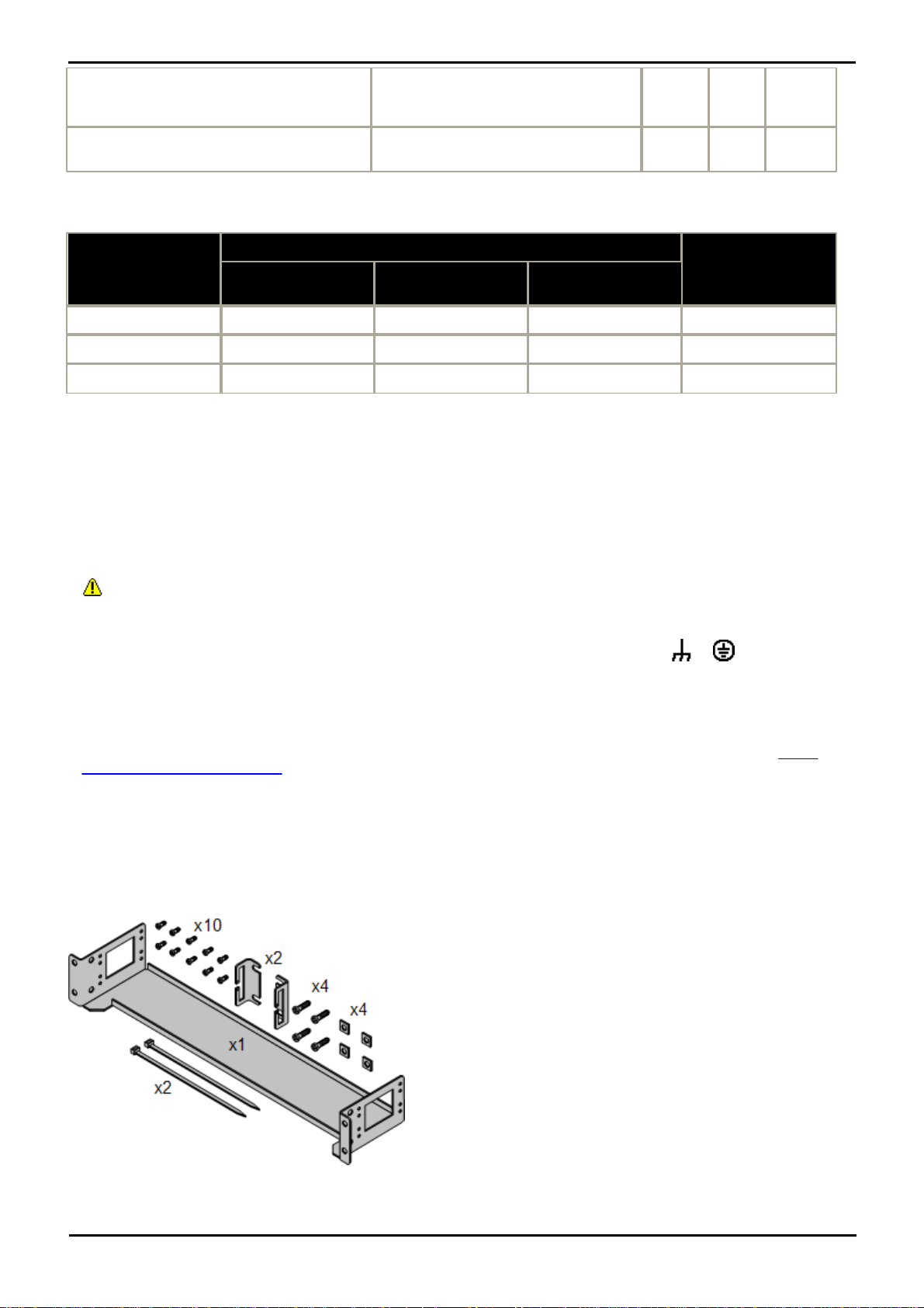
The IP Office 500v2 control unit and IP Office 500 external
expansion units can be rack mounted if required into 19-inch rack
systems. This requires an IP Office 500 Rack Mounting Kit (SAP
700429202) for each unit.
The kit includes:
· A rack mounting bracket and screws for attachment of the
bracket to the unit
· Nuts and bolts for rack attachment.
· Brackets and cable ties for cable tidying.
As indicated in the diagram following, the rack mounting bracket
can be used in several positions on the unit.
The table below details the maximum total cable distances for DS and analog extensions using different cable types.
3.2.7 Grounding
Use of ground connections reduces the likelihood of problems in most telephony and data systems. This is especially
important in buildings where multiple items of equipment are interconnected using long cable runs, for example phone
and data networks.
All IP Office control units and external expansion modules must be connected to a functional ground. In some cases, such
as ground start trunks, in addition to being a protective measure this is a functional requirement for the equipment to
operate. In other cases it may be a locale regulatory requirement and or a necessary protective step, for example areas
of high lightning risk.
· WARNING
During installation do not assume that ground points are correctly connected to ground. Test ground points before
relying on them to ground connected equipment.
The ground point on IP Office control units and external expansion modules are marked with a or symbol.
Ground connections to these points should use a 14 AWG solid wire with either a green sleeve for a functional ground or
green and yellow sleeve for a protective ground.
· Additional protective equipment
In addition to grounding, additional protective equipment will be required in the following situations. Refer to "Out of
Building Telephone Installations".
· On any Digital Station or Phones external expansion module connected to an extension located in another building.
3.2.8 Rack Mounting
PARTNER® Version, Installation and Reference Manual Page 33
- Issue 1a (30 January 2010)IP Office Essential Edition
Page 35

Environmental Requirements
In addition to the existing environmental requirements for an IP Office system, the following additional factors must be
considered when rack mounting a unit:
1.Rack Positioning - Ensure compliance with the rack manufacturers safety instructions. For example check that the
rack legs have been lowered and fixing brackets have been used to stop toppling.
2.Elevated Operating Ambient - If installed in a closed or multi-unit rack assembly, the operating ambient
temperature of the rack environment may be greater than room ambient. Therefore, consideration should be given
to installing the equipment in an environment compatible with the maximum ambient temperature (Tma) specified
by the manufacturer.
· Operating Temperature: 0°C (32°F) to 40°C (104°F).
· Operating Humidity: 10% to 95% non-condensing.
3.Reduced Air Flow - Installation of the equipment in a rack should be such that the amount of air flow required for
safe operation of the equipment is not compromised. Proper ventilation must be maintained. The side ventilation
slots on the IP Office 500 control unit should not be covered or blocked.
4.Mechanical Loading - Mounting of the equipment in the rack should be such that a hazardous condition is not
achieved due to uneven mechanical loading.
5.Circuit Overloading - Consideration should be given to the connection of the equipment to the supply circuit and
the effect that overloading of the circuits might have on over-current protection and supply wiring. Appropriate
consideration of equipment nameplate ratings should be used when addressing this concern.
6.Reliable Earthing - Reliable earthing of rack-mounted equipment should be maintained. Particular attention should
be given to supply connections other than direct connections to the branch circuit (e.g. use of power strips).
7. Only the screws (M3 x 6mm) provided with the mounting kit should used to attach the brackets to the control
unit.
PARTNER® Version, Installation and Reference Manual Page 34
- Issue 1a (30 January 2010)IP Office Essential Edition
Page 36
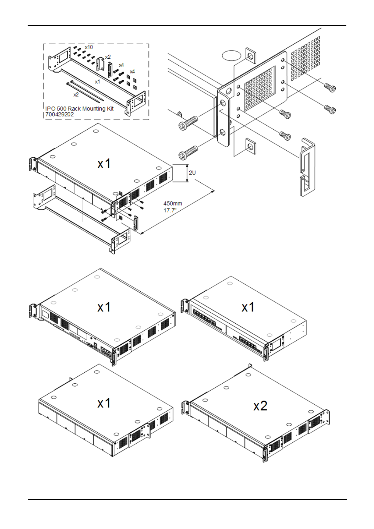
Installing PARTNER®: Getting Started
PARTNER® Version, Installation and Reference Manual Page 35
- Issue 1a (30 January 2010)IP Office Essential Edition
Page 37
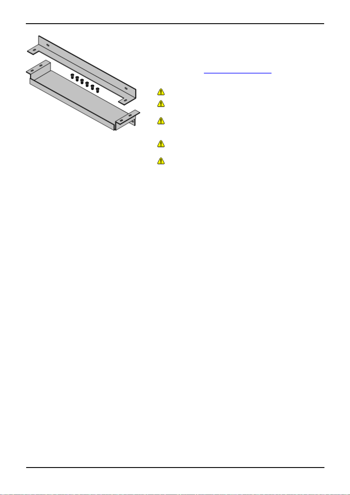
3.2.9 Wall Mounting
The IP Office 500v2 control unit can be wall mounted. This requires an IP
Office 500 Wall Mounting Kit (SAP 700430150) plus additional 4.5mm
fixtures and fittings suitable for the wall type. The wall mounting kit
includes two brackets, one top and one bottom.
Environmental Requirements
In addition to the existing environmental requirements for an IP Office
system, the following additional requirements apply when wall mounting
a unit:
· The wall surface must be vertical, flat and vibration free.
· A minimum clearance of 500mm (19.7 inches) is required on
all sides.
· The unit must be orientated as shown when mounted. That is
with the base card slots facing right when viewed from in front of
the unit.
· The brackets must be used as shown, with the deeper traylike bracket used at the bottom of the wall mounted control unit.
· Only the screws (M3 x 6mm) provided with the mounting kit
should used to attach the brackets to the control unit.
PARTNER® Version, Installation and Reference Manual Page 36
- Issue 1a (30 January 2010)IP Office Essential Edition
Page 38
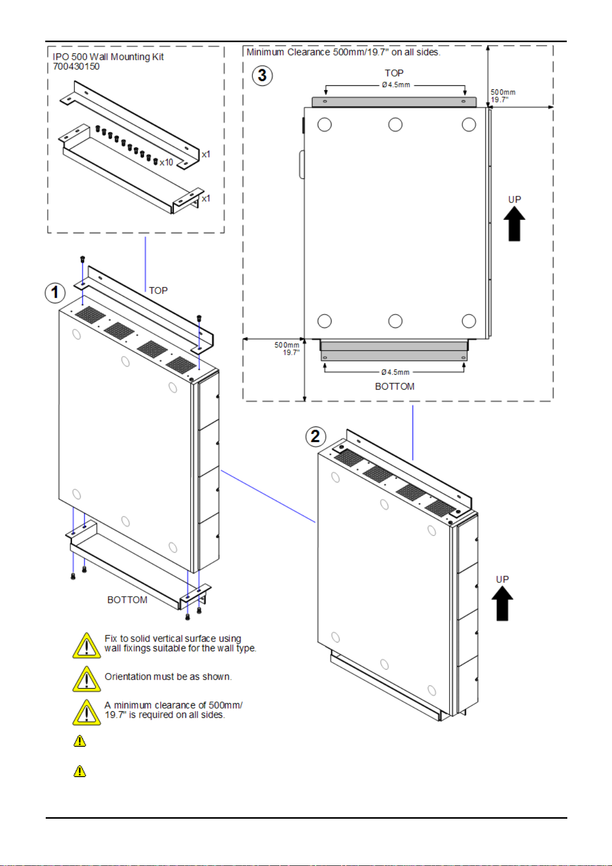
Installing PARTNER®: Getting Started
· The brackets must be used as shown, with the deeper tray-like bracket used at the bottom of the wall
mounted control unit.
· Only the screws (M3 x 6mm) provided with the mounting kit should used to attach the brackets to the control
unit.
PARTNER® Version, Installation and Reference Manual Page 37
- Issue 1a (30 January 2010)IP Office Essential Edition
Page 39
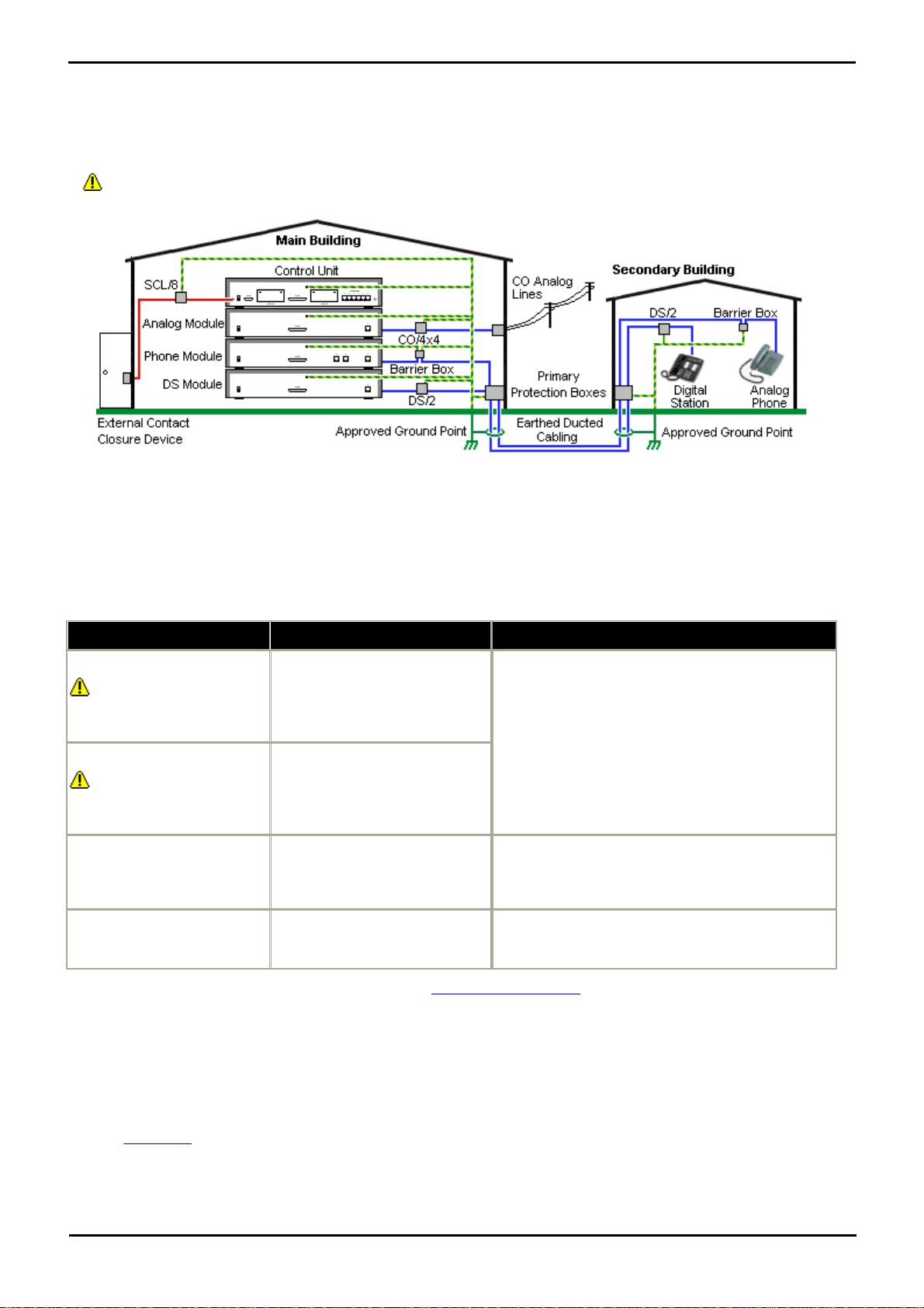
3.2.10 Lightning Protection/Out-of-Building Connections
Connection Type
Protection Device Type
Requirement
DS Phone Extensions
Digital Station Expansion
module DS ports only.
ITWLinx towerMAX DS/2
Supports up to 4 connections.
(This device was previously
referred to as the Avaya 146E).
· Connection from the expansion module to the
phone must be via a surge protector at each end
and via the primary protection point in each
building.
· The IP Office expansion module and control unit
and IROB devices must be connected to the
protective ground point in their building.
· The between building connection must be via
earthed ducting, preferable underground. The
cable must not be exposed externally at any point.
Analog Phone Extensions
Phones Expansion module (
POT or PHONE) ports only.
IP Office Barrier Box
Supports a single connection.
Maximum of 16 on any expansion
module.
Analog Trunks
ITWLinx towerMAX CO/4x4
Supports up to 4 two-wire lines.
(This device was previously
referred to as the Avaya 146C).
For locations where the risk of lightning strikes is felt
to be high, additional protection of incoming analog
trunks is recommended.
External Output Switch
ITWLinx towerMAX SCL/8
(This device was previously
referred to as the Avaya 146G)
Connections from an IP Office Ext O/P port to an
external relay device must be via a surge protector.
The following are the only supported scenarios in which wired extensions and devices outside the main building can be
connected to the IP Office system. In these scenarios, additional protection, in the form of protective grounding and
surge protectors, must be fitted.
· The fitting of additional protection does not remove the risk of damage. It merely reduces the chances of damage.
Cabling Requirements
· Cables of different types, for example trunk lines, extensions, ground and power connections, should be kept separate.
· All cabling between building should be enclosed in grounded ducting. Ideally this ducting should be buried.
· A Primary Protection Box must be provided at the point where the cables enter the building. This should be three point
protection (tip, ring and ground). Typically this would be gas tube protection provided by the local telephone company.
The ground wire must be thick enough to handle all the lines being affected by indirect strike at the same time.
The towerMAX range of devices are supplied by ITWLinx (http://www.itwlinx.com).
3.3 Install Overview
Essential Edition - PARTNER® Version is an out of the box installation and is meant to work correctly when it is switched
on, without requiring any setting up or pre configuration. The efficiency of this automatic procedure is simplified and
guaranteed by following a few basic rules in connecting up cable groups and populating the card slots of the control unit
as follows:
· Insert base cards working from left to right and do not leave unoccupied slots between cards.
· Apply simple housekeeping rules to cables by tying them in associated and clearly labeled bundles.
· Route cables carefully so that they do not intrude the working area or create a hazard
PARTNER® Version, Installation and Reference Manual Page 38
- Issue 1a (30 January 2010)IP Office Essential Edition
Page 40
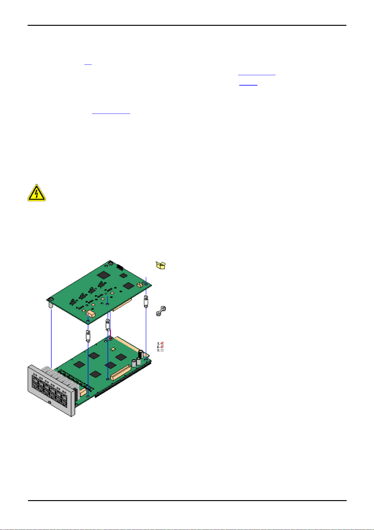
Installing PARTNER®: Install Overview
Parts and Equipment Required
1. IP500 base cards
2. IP500 Trunk cards if required
3. Stand Off Pillars, these are supplied with the trunk daughter card.
Tools Required.
1. 5mm Flat-blade screwdriver.
2. Anti-static wrist strap and ground point.
Procedure:
1.Check that correct cards have been supplied.
2.Ensure that you are wearing an anti-static wrist strap connected to a
suitable ground point.
3.On the base card identify the position of 3 holes for the plastic pillars
for the daughter card. These are along the same edge as the card
connector.
4.Fit the stand off pillars to the base card.
5.If there is a clip-on metal shield over the connector block on the
base card, remove it.
6.Using minimal force and checking that the pins are correctly located,
push the daughter trunk card down onto its connector block and the
stand off pillars.
7.Check that the card connector has snapped into position.
8.Using the washers and screws provided, secure the metal stand off
pillars to the base card.
The basic installation procedure described in the following sections is as follows:
1. Equip the control unit with base cards, pre fitted where necessary with daughter cards.
2. Insert the supplied SD card.
3. Connect a laptop PC that has IP Office Manager 6 or above, to the control unit (Item 5 in tools).
4. Switch ON the control unit. Essential Edition - PARTNER® Version automatically "sniffs" the connected system and
contacts the laptop. To do this, The control unit initializing firmware sends its configuration .ini files to the SD card
where they are checked against the current versions on the card. The control unit performs a boot up sequence that
varies according to what is detected during the discovery phase.
5.Switch ON the laptop. Office Manager on the PC displays the administration home screen which identifies basic system
components and system settings.
6.Plug in telephone handsets.
7.Use Manager to complete system configuration.
3.4 Card Installation
This section describes in order, the procedures to equip an IP 500v2 control unit for use with Essential Edition PARTNER® Version.
Warnings
· Correct anti-static protection steps should be taken before handling circuit boards.
· During this process power to the IP Office control unit must be switched off and disconnected.
IP500 Trunk Daughter Card Preparation
IP500 trunk daughter cards should be fitted to any base card requiring them.
PARTNER® Version, Installation and Reference Manual Page 39
- Issue 1a (30 January 2010)IP Office Essential Edition
Page 41
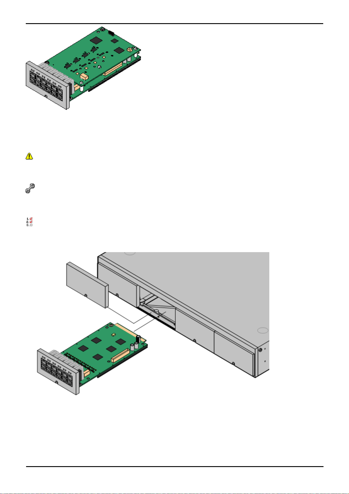
9.A set of labels are supplied with the trunk daughter card. Fit the
appropriate label to the front of the base card.
10.Prepare any other base cards. Then proceed to inserting the base
cards.
Base Card Installation
Having prepared each base card by adding any daughter cards required, the base cards can be inserted into the control
unit.
Warnings
· Correct anti-static protection steps should be taken before handling circuit boards.
· During this process power to the IP Office control unit must be switched off and disconnected.
Tools Required.
· o 5mm Flat-blade screwdriver.
· o Anti-static wrist strap and ground point.
Procedure:
1.Using a flat-bladed screwdriver, remove the covers from the slots on the front of the control unit. This cover is no
longer required but should be retained until installation has been completed.
2.Allowing the card to rest against the bottom of the slot, begin sliding it into the control unit. When half inserted,
check that the card rails have engaged with the slot edges by trying to gently rotate it. If the card does rotate
remove it and begin inserting it again.
3.The card should slide in freely until almost fully inserted. At this point apply pressure at the base of the front of the
card to complete insertion into its connector block.
4.Using a flat-bladed screwdriver secure the base card.
General Notes
PARTNER® Version, Installation and Reference Manual Page 40
- Issue 1a (30 January 2010)IP Office Essential Edition
Page 42
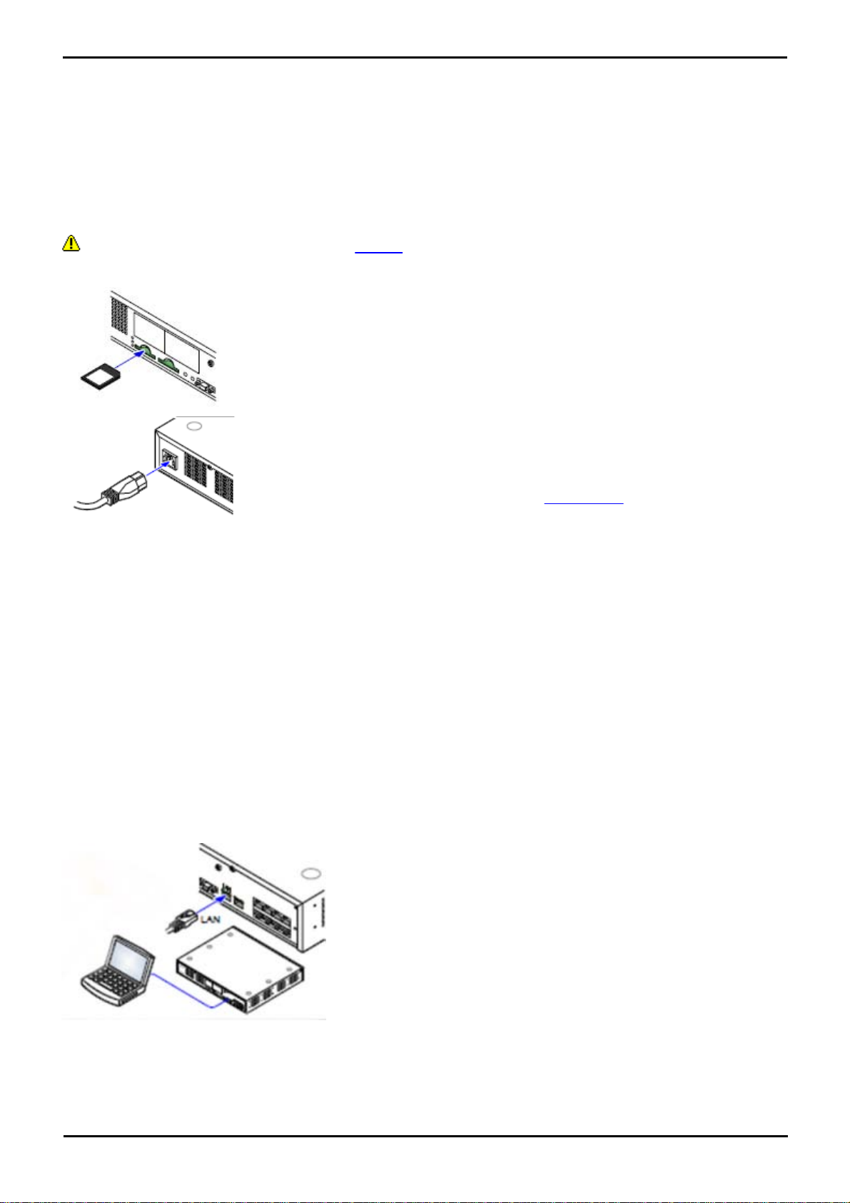
Installing PARTNER®: Card Installation
With power still off, insert the SD card into the first rear panel slot
(System SD) of the control unit.
Apply power to the control unit.
Check that the orange LED lamp on the IP Office LAN port is on. The
green LED may also be flickering as it indicates traffic across the LAN
connection
As the control unit goes through its start-up cycle, make the following
checks:
1.The CPU LED changes to green
When power to the control unit is switched on, the normal sequence for
the CPU LED is as follows.
a) Steady Red for 3 seconds
b) Off for 10 seconds
c) Flashing alternate red/green for 4 seconds.
d) The LED should be steady green following successful start up. Note that
the IP Office 500 cards on the front of the control unit may still be going
through their own start up process.
· Flashing RED
A flashing red CPU LED at this stage indicates an error. The most likely
cause is a missing or loose SD card.
2.The System SD LED changes to green
3.The LAN connection LED flashes and then settles to steady green
4.Card module front lamps light randomly but after approximately 30
second the No.1 lamps flash together once every 5 seconds
Connect the laptop via an R45 lead to the LAN socket on the control unit
rear panel.
Switch on the laptop and start the Manager application. It should
automatically recognize the control unit and the software controlling it.
IP Office Manager can now be used to configure the extensions and trunk
lines. See IP Office Essential Edition - PARTNER® Version Administration
Toll User Manual.
· Cards can be fitted in any order into any available slots. The only exception is the IP500 4-Port Expansion card
which can only be installed in right hand slot 4.
· It is recommended that cards are fitted from left to right.
· There are restrictions to the number of supported cards of some types. When such a limit is exceed, the right-
most card of that type will not function.
· Ensure that you use the labels supplied to identify the card fitted into the control unit.
3.5 Starting
Do not begin this procedure until all cards are installed in the control unit.
PARTNER® Version, Installation and Reference Manual Page 41
- Issue 1a (30 January 2010)IP Office Essential Edition
Page 43

3.6 Connections
If the site already has a patch panel for all outside lines and extensions, you should be able to use the existing wiring to
install the system hardware and connect telephones to the system yourself.
During control unit startup
· Extensions and Users
A user is automatically created for each physical extension port detected in the system. Users are assigned
extension numbers starting from 201. User names take the form Extn201, Extn202, ....
· Hunt Group
A single hunt group 200 called Main is created and the first 10 users are placed into that hunt group as members.
· Incoming Call Routes
Two default incoming call routes are created. Voice calls are routed to the hunt group Main.
Installing Telephones
After you have installed the IP Office 500v2 control unit and have connected the line and extension cords, you are ready
to install the telephones. Installing the telephones includes assembling, testing and connecting, the telephone. As
desired, you also can connect an Intercom Autodialer to certain telephones
Assembling PARTNER® Version Telephones
All PARTNER telephones are shipped with a stand for either desk-mounting or wall-mounting the telephone. For other
telephones, see the instructions that are provided with the telephone.
Gather the line and extension cords hanging from the control unit and twist-tie or wire-wrap them.
Testing the modules
1.Test the base card modules by doing the following:
a.Plug a system telephone into the first port on each module.
b.Press the line button on the telephone for each outside line and listen for a dial tone.
Connecting handsets
2.For telephone systems that are based on a patch (intermediate) connection system:
a.Connect line cords to the line jacks on the modules.
b.Connect the free end of each line cord to the appropriate telephone network interface jack
3. Fill each module before moving to the next module to the right
As each handset is connected any necessary software it contains is automatically checked and updated as necessary.
3.7 Final Actions
You may be required to compile calling lists, build groups and allocate permissions etc. before leaving the customer
premises. This depends on arrangements made between your local office and the customer. If required, use Manager to
create any lists. Changes to the basic Essential Edition - PARTNER® Version configuration, setting up trunks, adding
licenses etc. are detailed in the Avaya IP Office <%SHORTNAME%> Administrator Tool User Guide identified in the
Introduction.
As you use Manager to make changes to the <%SHORTNAME%> setup, you are prompted to save or discard
changes you have made before leaving any administration window to go on to another task. However, you should
remember that you are accumulating these changes in a COPY of the control unit configuration file which must be
saved back to the SD card before changes are effective. Similarly, system changes such as plugging in handsets
during this time are recognized by the <%SHORTNAME%> system control unit but are undetected by Manager which
is working with a copy of the configuration file. Avaya recommend that whilst using Manager you save the
configuration file at frequent intervals to ensure the working copy and Manager copy of the configuration file remain
as compatible as possible.
Do not leave the Manager application open for long periods and particularly when it is not being used.
Check system operation and gather all packing materials for disposal.
If appropriate, obtain sign-off signature.
PARTNER® Version, Installation and Reference Manual Page 42
- Issue 1a (30 January 2010)IP Office Essential Edition
Page 44

Installing PARTNER®: Final Actions
PARTNER® Version, Installation and Reference Manual Page 43
- Issue 1a (30 January 2010)IP Office Essential Edition
Page 45

Page 46

Chapter 4.
System Component Details
PARTNER® Version, Installation and Reference Manual Page 45
- Issue 1a (30 January 2010)IP Office Essential Edition
Page 47
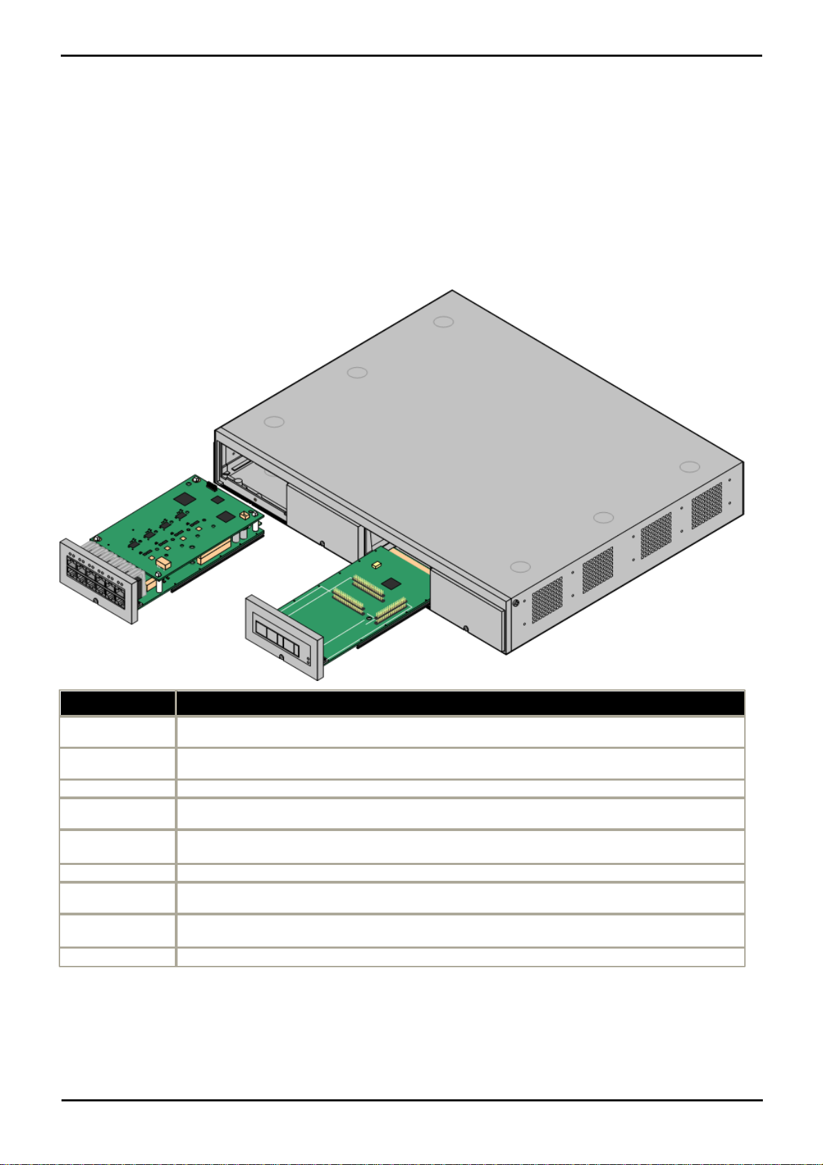
4. System Component Details
Feature
Capacity
Maximum
Extensions
Up to 48 extension ports of which there may be a maximum of 18 ETR ports.
Conference
Parties
10 as standard with no silence suppression.
Trunks Cards
Any combination of IP Office 500trunk daughter cards and up to 2 IP400 trunk cards.
Voicemail
Channels
Maximum 2, expandable to 6 subject to available licenses.
Software Level
· IP Office core software level 6.0 minimum.
· Bin file = ip500v2.bin.
Power Supply
Internal power supply unit.
Mounting
Free-standing, rack mounted (requires IP Office 500Rack Mounting Kit) or wall mounted (requires IP
Office 500Wall Mounting Kit).
Dimensions
Width: 445mm/17.5". Depth: 365mm/14.4". Height: 73mm/2.9"/2U.
Clearance: 90mm minimum all sides, 220m at front. 500mm all side when wall mounted.
Memory
Maximum configuration file size: 2048KB.
This section contains detailed descriptions of each of the component parts of Essential Edition - PARTNER® Version.
4.1 Control Unit
The base item of the IP Office system is the system server or control unit. It stores the system configuration and controls
system operation. The Essential Edition - PARTNER® Version system uses the IP Office 500v2 model R6.0 control unit.
A control unit can be customized by adding various internal cards such as trunk cards. An external expansion module can
be also be connected.
The slots are numbered 1 to 4 from left to right. They can be used in any order. However if the capacity for a particular
type of card is exceeded, the card in the rightmost slot will be disabled. The unit must not be used with uncovered slots.
PARTNER® Version, Installation and Reference Manual Page 46
- Issue 1a (30 January 2010)IP Office Essential Edition
Page 48
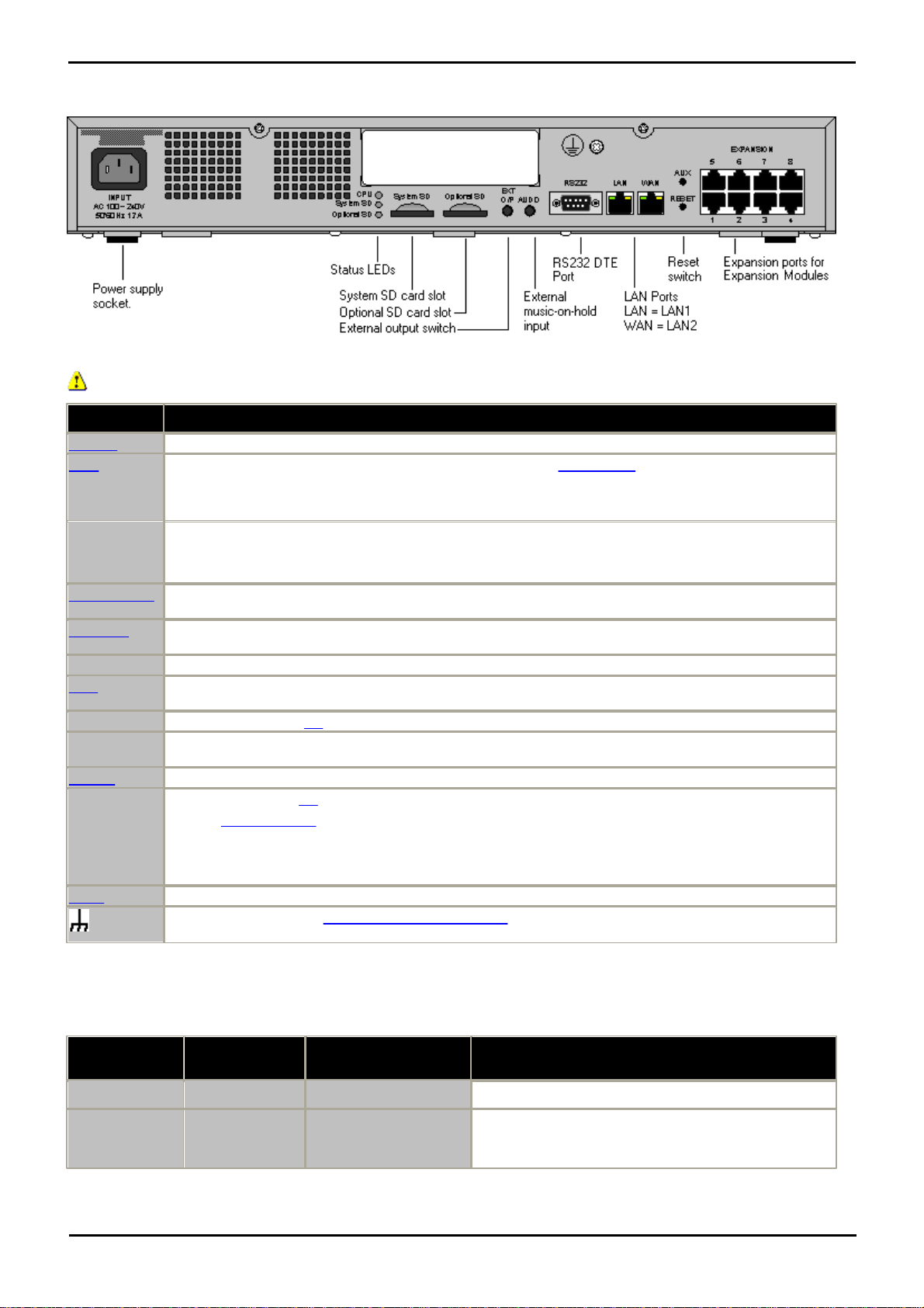
4.1.1 Rear Connections
Ports
Description
AUDIO
3.5mm Stereo jack socket. Used for external music on hold source input.
AUX
If pressed during a restart of the control unit, the control unit skip booting from the /primary folder on
the System SD card.
If pressed for between 5 and 10 seconds when a system is running, the control unit will shutdown for 10
minutes.
CPU
Indicates the status of the control unit.
· Alternate red/green = Starting up.
· Green on = Okay.
· Red on = No software.
· Flashing Red = Error/Shutdown.
EXPANSION
RJ45 socket. Used for direct connection to external expansion modules using the Expansion Interconnect
cable supplied with the expansion module.
EXT O/P
3.5mm Stereo jack socket. Used for switching external relay systems such as door entry controls. The
port contains two independent switches controlled by the IP Office.
INPUT
AC power input port.
LAN
RJ45 socket. With the WAN port forms a managed layer 3 Ethernet switch. The ports are full-duplex
10/100Mbps auto-sensing, MDI crossover ports.
Optional SD
Used for the Optional SD card. The LED is used in the same way as for the System SD (see below).
RESET
This switch is used to restart the IP Office, optionally erasing the configuration and or the core software
in the process. See table below.
RS232
9-Way D-Type socket. Used for system maintenance.
System SD
Used for the System SD card,. The LED is used as follows.
· Off = Card shutdown.
· Green on = Card present.
· Green flashing = Card in use.
· Orange steady = Reset imminent.
· Red flashing = Card initializing or shutting down.
· Red fast flashing = Card full
· Red steady = Card failure/wrong type.
WAN
Not used in Essential Edition - PARTNER® Version
Used for connection of a function or protective ground. Use of a ground for all systems is recommended
and for some locales may be a regulatory requirement.
Press Duration
(seconds)
CPU LED
Action
Summary
0 to 5.
Off
None
None.
5 to 10.
Orange
Reboot When Free
Reboot when free with new incoming/outgoing call
barring. A reboot using the reset button is recorded in
the Audit Trail.
Only Port 1 of the extreme right hand expansion ports should be used.
System Component Details: Control Unit
Reset button.
Pressing the button while the control unit is starting up will pause the start up until the button is released. The effect of
pressing the button during normal operation will depend on how long the button is pressed and is indicated by the CPU
LED.
PARTNER® Version, Installation and Reference Manual Page 47
- Issue 1a (30 January 2010)IP Office Essential Edition
Page 49
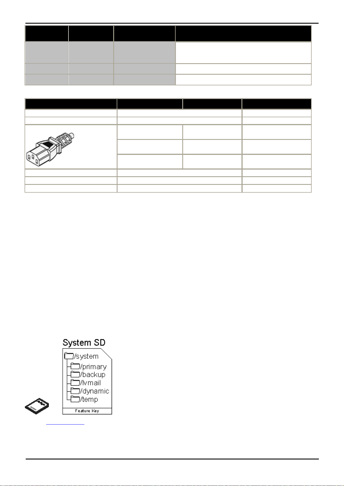
Press Duration
(seconds)
CPU LED
Action
Summary
10 to 30.
Flashing orange
Erase Configuration/
Immediate Reboot
Erase the configuration, alarm log and audit trail.
Immediate reboot without waiting for active calls to end.
30 to 40.
Red
Erase All.
Erase configuration, alarm log and core software.
Over 40.
Flashing green
None
None.
Name
Description
Country
Part number
IPO 500 V2 Base Unit
IP Office 500 V2 Base Unit
700476005
Avaya SD Memory Card
IPO System SD Card Partner® Version
700479728
IEC60320 C13 Earthed Power Cord
CEE7/7
Europe
700289762
BS1363
United Kingdom
700289747
NEMA5-15P
America
700289770
IP Office 500Rack Mounting Kit
IP Office 500Rack Mounting Kit
700429202
IP Office 500Wall Mounting Kit
IP Office 500Wall Mounting Kit
700430150
IP Office 500Blanking Plate Kit
IP Office 500Blanking Plate Kit
700429194
4.2 SD Card
The Avaya SD card exercises central control over the Essential Edition - PARTNER® Version system and acts as the
License authorization for the control unit. The SD card is inserted into the System SD slot on the rear of the control
unit.
Except when necessary during maintenance, the System SD slot should contain an Avaya SD card at all times. The files
on that card are used when the system is started and the Feature Key serial number, only present on Avaya cards, is
used for the licensing of IP Office features.
· The control unit has two SD card slots labeled System SD and Optional SD.
· The system SD card is also used to store copies of core software binary files, configuration files and backups as well as
the voice mail application and the system status application.
· Embedded voicemail on the SD card provides 2 channels by default but can be licensed for up to 6 channels total.
· Various commands within the Manager interface enables the SD card contents to be backed up, restored or copied.
These actions can also be achieved via the handset; instructions to do this are provided in the system TUI guide.
· The additional SD card slot can be used to store occasional full copies of the System SD card. or as an additional
memory card to or from which, files can be copied. Non-Avaya cards can be used for this as long as they conform to
the standard below:
SDHC minimum 4GB FAT32 format (Single partition, SDHC, class2+, FAT32, SPI & SD bus).
See also SD Card Actions
PARTNER® Version, Installation and Reference Manual Page 48
- Issue 1a (30 January 2010)IP Office Essential Edition
Page 50
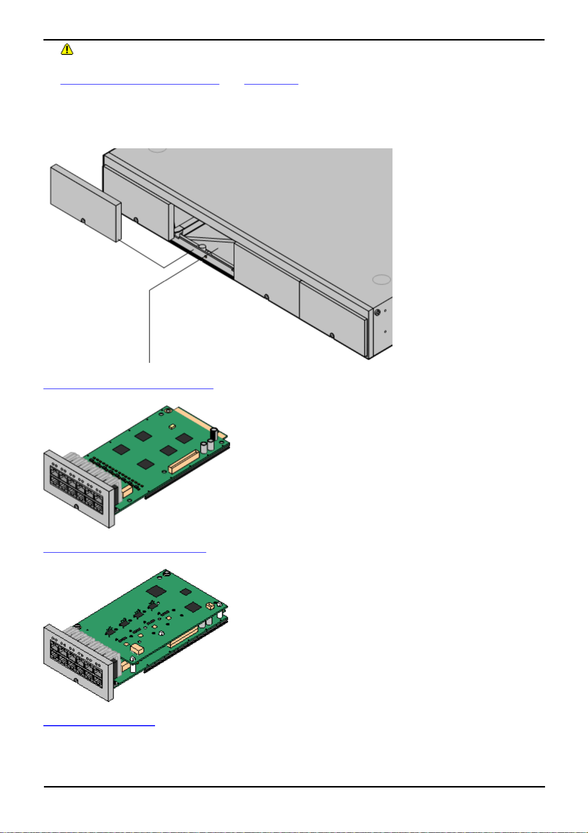
System Component Details: SD Card
The IP Office 500v2 control unit
has 4 slots to accomodate base
cards. Each base cards includes
an integral front panel with
ports for cable connections.
The slots are numbered 1 to 4
from left to right. Normally they
can be used in any order,
however if the capacity for a
particular type of card is
exceeded, the card in the
highest slot will be disabled.
IP Office 500 Analog Phone Base Card
This card has 12 RJ45 ports. The card is available in two variants,
providing 2 or 8 analog extension ports for the connection of analog
phones. The card can be fitted with an IP Office 500 daughter card
which then uses the additional 4 RJ45 ports for connections.
· This card accepts one IP Office 500 daughter card of any type.
· Maximum: 4 per control unit.
· When fitted with an IP Office 500 Analog Trunk daughter card, the
Phone 8 base card supports 1 power failure extension to trunk (loopstart only) connection.
· The analog extension ports do not include a ringing capacitor. Where
this is a requirement, connection should be via a Master socket
containing ringing capacitors.
IP Office 500 ATM Combination Card
This card provides 6 digital station ports (1-6), 2 analog extension
ports (7-8) and 4 analog trunk ports (9-12). The card also includes 10
VCM channels.
· This card has a pre-installed IP Office 500 ATM daughter card.
· Maximum: 2 combination cards per control unit.
· During power failure port 8 is connected to port 12.
IP Office ETR6 Base Card
This card is only supported in an IP500 V2 control unit running in
PARTNER® Version mode. It provides 6 ETR ports for connection of
ETR phones. 2 Analog extension ports are also provided for emergency
use only with an analog trunk card.
SD Card Removal
SD cards should never be removed while being used. Though the SD card slot LEDs indicate when data is being
written to an SD card, lack of flashing LED is not a sufficient safeguard. The IP Office Manager provides methods to
shutdown and restart an individual card or to shutdown the Essential Edition - PARTNER® Version system in order to
allow removal of an SD card. If the System SD card is removed, licensed features will continue operating for up to 2
hours.
4.3 Base Cards
PARTNER® Version, Installation and Reference Manual Page 49
- Issue 1a (30 January 2010)IP Office Essential Edition
Page 51
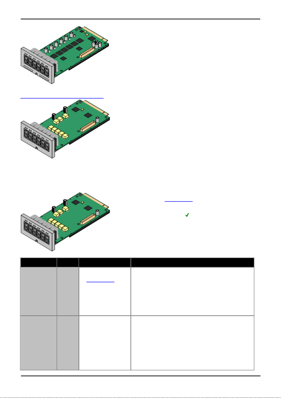
· The card can be fitted with an IP500 trunk daughter card which uses
the base card ports for trunk connection.
· Maximum: 3 per control unit.
· The analog phone ports do not include a ringing capacitor. Where
this is a requirement, connection should be via a Master socket
containing ringing capacitors.
· If fitted with an IP Office 500 Analog Trunk daughter card, during
power failure phone ports 7 and 8 are connected to analog trunk
port 12. However during normal operation analog phone ports 7 and
8 are not useable.
IP500 Digital Station Base Card
This card provides 8 DS (digital station) ports for the connection of
Avaya digital phones other than IP phones.
· The card can be fitted with an IP Office 500 trunk daughter card
which uses the base card ports for trunk connection.
· Maximum: 3 per control unit.
· 4400 Series phones (4406D, 4412D and 4424D) are not supported
on this card. They are supported on an external expansion module.
· Supports
Provides 8 DS ports for digital stations supported
· Maximum per Control Unit: 3.
· IP500 Daughter Card Support: 1.
Port Type
Ports
Features
Port LEDs
Digit Station
1 to 8
Phrase IP500 Analog
PortsProvides DS ports
for digital stations (except
4406D, 4412D and
4424D).
· Green On - Phone detected.
· LED1 is used for base card status:
· Red On = Error
· Red Slow Flash = Initializing.
· Red Flash every
5 seconds =
Card okay.
· Red Fast Flash =
System
shutdown.
Optional Trunk
Card Ports
9 to 12
The card can be fitted
with one of the following
trunk daughter cards. The
trunk daughter card then
uses ports 9 to 12 on the
base card for its trunk
connections.
· IP500 Analog
Trunk Card.
LED use depends daughter card type fitted.
· LED 9 is used for daughter card status.
· Red On = Error
· Red Slow Flash = Initializing.
· Red Flash every
5 seconds =
Card okay.
· Red Fast Flash =
System
shutdown.
Analog Trunk Daughter Card
4.3.1 Digital Station
This card is used to add digital station (DS) extension ports to the IP 500v2 control unit. It provides 8 RJ45 DS extension
ports for use with Avaya digital phones not including IP phones. A further 4 RJ45 ports are provided for trunk connections
when an IP500 trunk card is fitted to this card.
PARTNER® Version, Installation and Reference Manual Page 50
- Issue 1a (30 January 2010)IP Office Essential Edition
Page 52
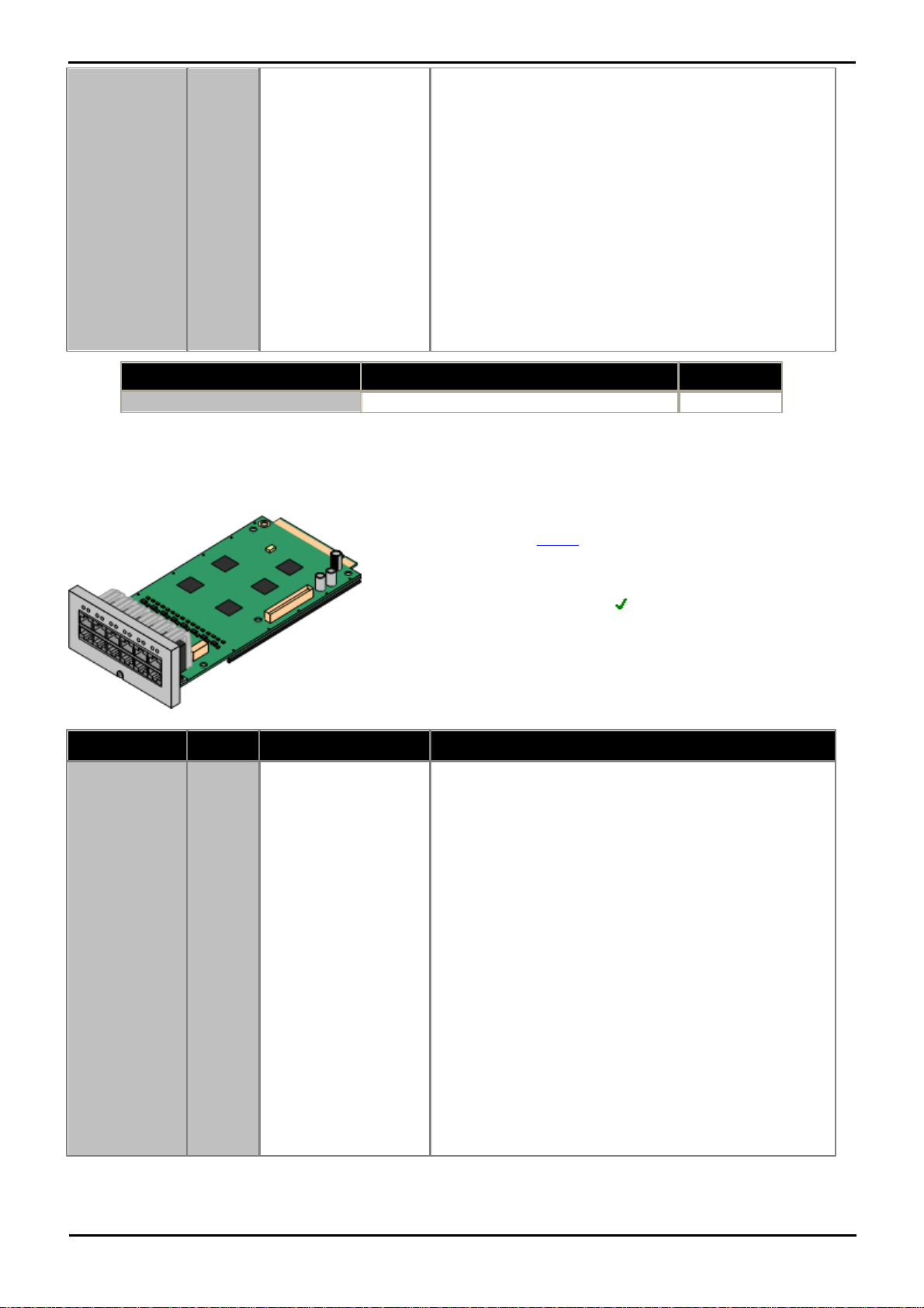
System Component Details: Base Cards
· IP500 PRI Trunk
Card.
· Green on: Card fitted.
· Green flashing: Trunk in use.
PRI Trunk Daughter Card
· Off: No trunk present.
· Green on: Trunk present.
· Green flashing: Trunk in use.
· Red/Green Fast
Flash (port 9) or
Green Fast Flash
(port 10): Alarm
indication signal
(AIS) from the
trunk remote end.
· Red with Green
Blink (port 9) or
Green Blink (port
10): Port in
loopback mode (set
through IP Office
System Monitor).
Name
Description
Part Number
IPO 500 Extn Card Dgtl Sta 8
IP Office 500 Extension Card Digital Station 8
700417330
· Supports
Provides either 8 or 2 analog phone ports depending on card
variant.
· Maximum per control unit: 4.
· IP500 Daughter Card Support: 1.
Port Type
Ports
Features
Port LEDs
Analog
Extension
1 to 8
· Phrase IP500 ETR Port
Supports ICLID modes
DTMFA, DTMFC,
DTMFD, FSK and UK20.
· REN 2 (1 for external
bell device).
· Off-Hook current:
25mA
· Ring Voltage: 40V.
· Intended for
connection to two-wire
analog phones, the
ports do not include a
ringing capacitor. For
connection to 4-wire
analog phones,
connection should be
via a master socket
with ringing capacitors.
· If fitted with an analog
trunk card, for the
Phone 8, during power
failure extension port 8
is connected to the
analog trunk port 12.
No status LEDs are used for analog phone extensions.
· LED1 is used for base card status:
· Red On = Error
· Red Slow Flash = Initializing.
· Red Flash every
5 seconds =
Card okay.
· Red Fast Flash =
System
shutdown.
4.3.2 Analog Phone
This card is used to add analog phone extension ports to the IP 500v2 control unit. It is available in two variants,
providing either 2 or 8 analog extension ports.
PARTNER® Version, Installation and Reference Manual Page 51
- Issue 1a (30 January 2010)IP Office Essential Edition
Page 53

Optional Trunk
Card Ports
9 to 12
The card can be fitted
with one of the following
trunk daughter cards. The
trunk daughter card then
uses ports 9 to 12 on the
base card for its trunk
connections.
· IP500 Analog
Trunk Card.
· IP500 PRI Trunk
Card.
LED use depends daughter card type fitted.
· LED 9 is used for daughter card status.
· Red On = Error
· Red Slow Flash = Initializing.
· Red Flash every
5 seconds =
Card okay.
· Red Fast Flash =
System
shutdown.
Analog Trunk Daughter Card
· Green on: Card fitted.
· Green flashing: Trunk in use.
PRI Trunk Daughter Card
· Off: No trunk present.
· Green on: Trunk present.
· Green flashing: Trunk in use.
· Red/Green Fast
Flash (port 9) or
Green Fast Flash
(port 10): Alarm
indication signal
(AIS) from the
trunk remote end.
· Red with Green
Blink (port 9) or
Green Blink (port
10): Port in
loopback mode (set
through IP Office
System Monitor).
Name
Description
Part Number
IPO 500 Extn Card Phone 2
IP Office 500 Extension Card Phone 2
700431778
IPO 500 Extn Card Phone 8
IP Office 500 Extension Card Phone 8
700417231
4.3.3 ETR6 Card
· Supports
ETR and analog phones.
· Maximum per IP500 Control Unit: 3.
· IP500 Daughter Card Support: 1.
The IP500 BRI trunk daughter card is not supported.
Port Type
Ports
Features
Port LEDs
ETR
Extensions
1 to 6
Each ETR phone can be
used for an ETR or
analog phone. Support
for ETR 34D phone is
limited to a maximum of
2 per ETR6 card and 4
in total.
· REN 1.
· DTMF dialing only.
· Message waiting
indication 51V
stepped.
No status LED are used for ETR ports.
· LED1 is used for base card status:
· Red On = Error
· Red Slow Flash = Initializing.
· Red Flash every 5
seconds = Card okay.
· Red Fast Flash =
System shutdown.
This card is used to add 6 ETR phone extension ports to the IP 500v2 control unit. This card is only supported by IP500
V2 systems running in Essential Edition - PARTNER® Version mode.
It also includes 2 analog extension ports which are for emergency use only when the card is fitted with an analog trunk
daughter card. A further 4 RJ45 ports (9 to 12) are provided for trunk connections when an IP500 trunk daughter card is
fitted to this card.
PARTNER® Version, Installation and Reference Manual Page 52
- Issue 1a (30 January 2010)IP Office Essential Edition
Page 54

System Component Details: Base Cards
Port Type
Ports
Features
Port LEDs
· ICLID mode Bellcore
202.
EF
7 to 8
· If fitted with an IP500
Trunk Daughter card,
during power failure
both these ports are
connected to analog
trunk port 12.
· Phrase IP500 ETR
PortSupports ICLID
modes DTMFA,
DTMFC, DTMFD, FSK
and UK20.
· REN 2 (1 for external
bell device).
· Off-Hook current:
25mA
· Ring Voltage: 40V.
· Intended for
connection to twowire analog phones,
the ports do not
include a ringing
capacitor. For
connection to 4-wire
analog phones,
connection should be
via a master socket
with ringing
capacitors.
No status LEDs are used for analog phone extensions.
Optional
Trunk Ports
9 to 12
The ETR6 can be fitted
with an Analog Trunk
card
LED use depends daughter card type fitted.
· LED 9 is used for daughter card status.
· Red On = Error
· Red Slow Flash = Initializing.
· Red Flash every 5
seconds = Card okay.
· Red Fast Flash =
System shutdown.
Analog Trunk Daughter Card
· Green on: Card fitted.
· Green flashing: Trunk in use.
PRI Trunk Daughter Card
· Off: No trunk present.
· Green on: Trunk present.
· Green flashing: Trunk in use.
· Red/Green Fast Flash
(port 9) or Green Fast
Flash (port 10): Alarm
indication signal (AIS)
from the trunk remote
end.
· Red with Green Blink
(port 9) or Green Blink
(port 10): Port in
loopback mode (set
through IP Office System
Monitor).
Name
Description
Part Number
IPO 500v2 EXTN CARD ETR6
IP Office 500v2 EXTN CARD ETR6
700476039
PARTNER® Version, Installation and Reference Manual Page 53
- Issue 1a (30 January 2010)IP Office Essential Edition
Page 55
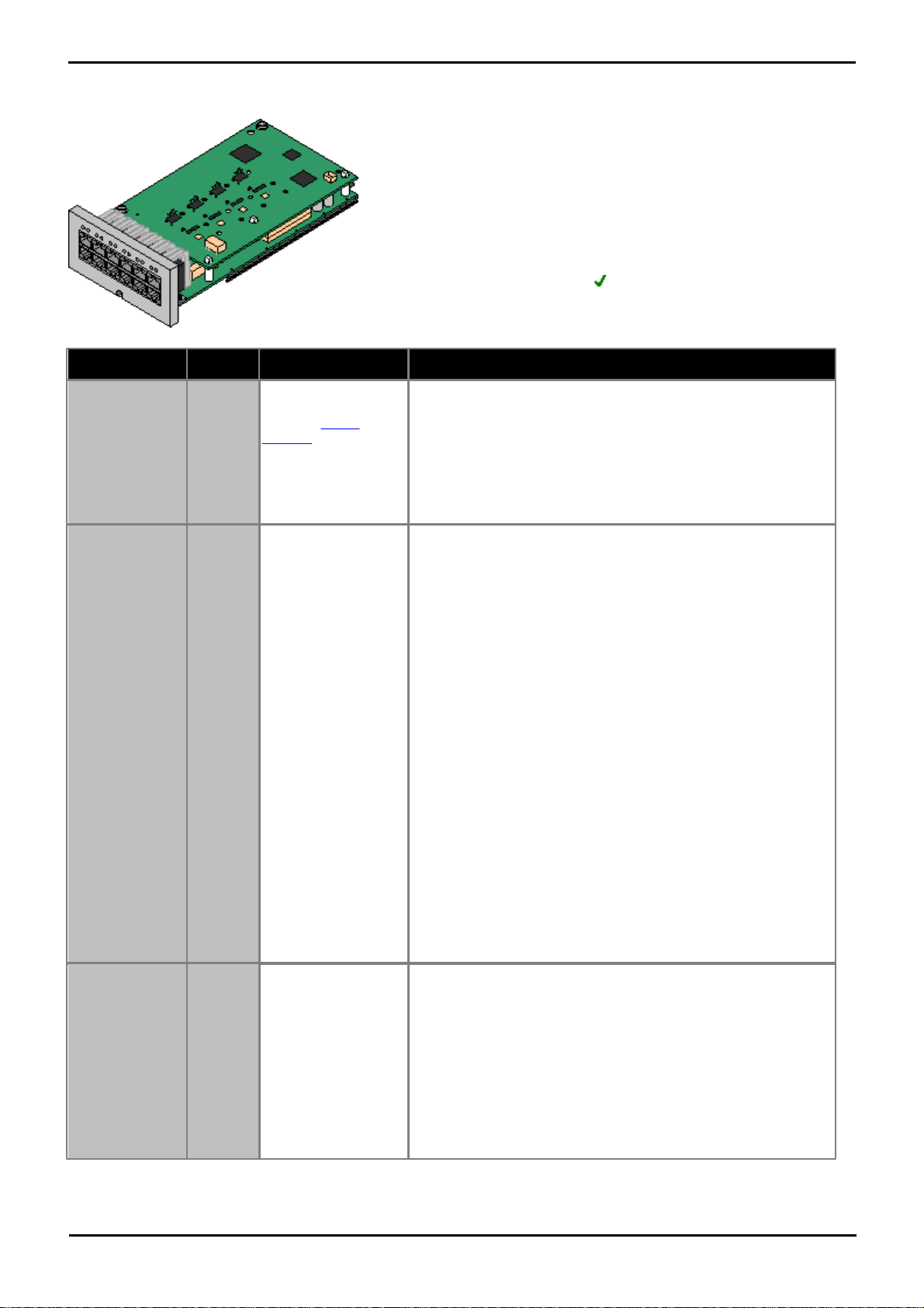
4.3.4 ATM Combination Card
· Supports
· 6 Digital Station ports.
· 2 Analog Extension ports.
· 4 Analog Trunk ports.
· 10 VCM channels.
· Maximum per Control Unit: 2.
· IP500 Daughter Card Support: 1. The trunk daughter card is pre-
installed and cannot be replaced with another card type.
Port Type
Ports
Features
Port LEDs
Digital Station
1 to 6
Phrase IP500 Analog
PortsProvides DS
ports for digital
stations (except
4406D, 4412D and
4424D).
· Green On - Phone detected.
· LED1 is used for base card status:
· Red On = Error
· Red Slow Flash = Initializing.
· Red Flash every 5
seconds = Card
okay.
· Red Fast Flash =
System shutdown.
Analog
Extension
7 to 8
· Phrase IP500 ETR
PortSupports ICLID
modes DTMFA,
DTMFC, DTMFD,
FSK and UK20.
· REN 2 (1 for
external bell
device).
· Off-Hook current:
25mA
· Ring Voltage: 40V.
· Intended for
connection to twowire analog phones,
the ports do not
include a ringing
capacitor. For
connection to 4wire analog phones,
connection should
be via a master
socket with ringing
capacitors.
· During power
failure extension
port 8 is connected
to the analog trunk
port 12.
No status LEDs are used for analog phone extensions.
Analog Trunk
9 to 12
· DTMF, ICLID, Busy
tone detection.
· Over-voltage and
lightning protection.
· DTMF and LD
dialing.
· Adjustable echo
cancellation (default
16ms). Selectable
to Off, 8, 16, 32, 64
and 128
milliseconds.
· Green on: Card fitted.
· Green flashing: Trunk in use.
· LED 9 is used for daughter card status.
· Red On = Error
· Red Slow Flash = Initializing.
· Red Flash every 5
seconds = Card
okay.
· Red Fast Flash =
System shutdown.
This card is used to add a combination of ports to the IP 500v2 control unit.
PARTNER® Version, Installation and Reference Manual Page 54
- Issue 1a (30 January 2010)IP Office Essential Edition
Page 56
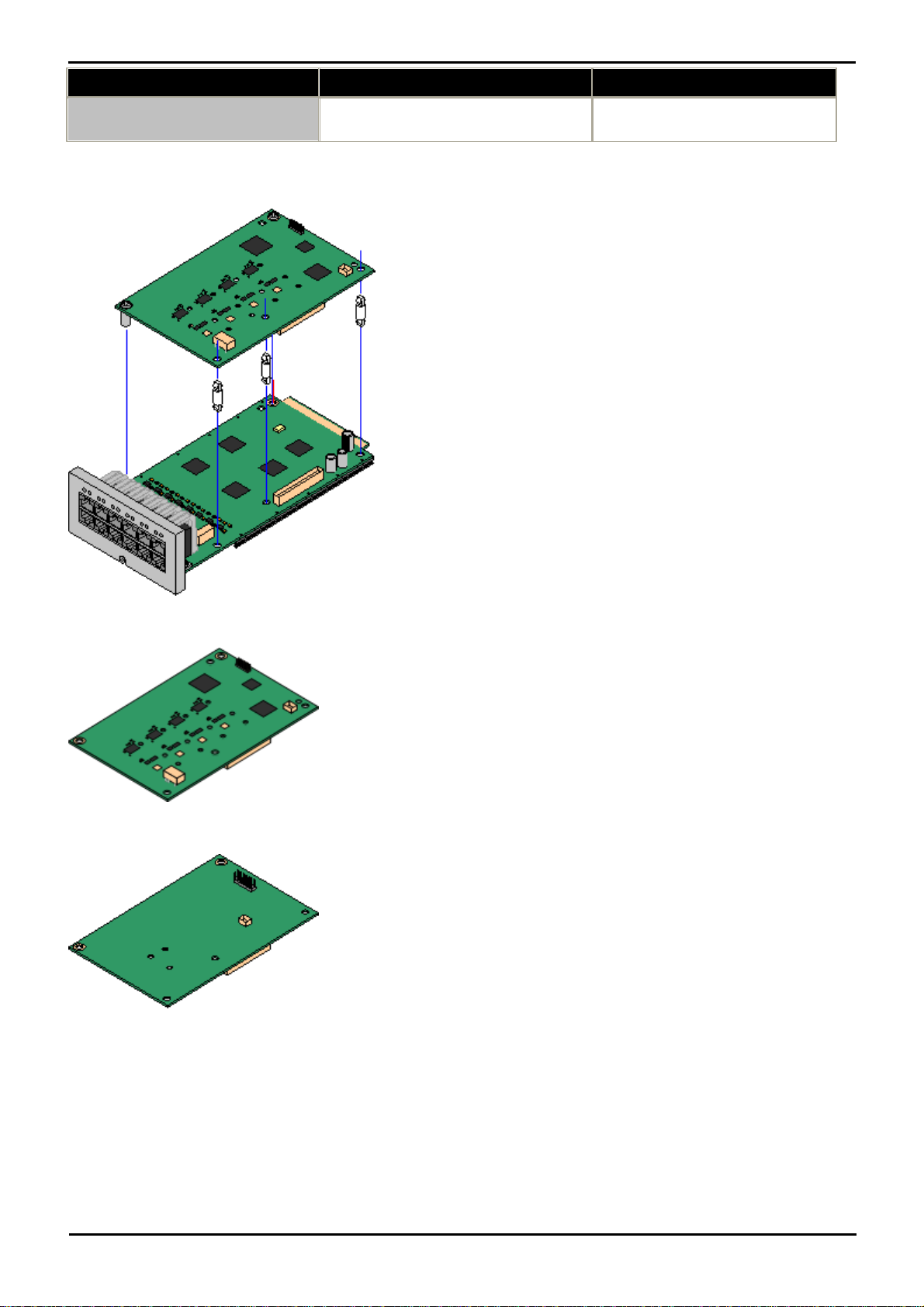
Name
Description
Part Number
IPO 500v2 COMBINATION CARD
ATM
IP Office 500v2 COMBINATION CARD ATM
700476013
4.4 Trunk Cards
IP Office 500 daughter trunk cards can be fitted to IP Office 500
base cards to provide support for trunk. The daughter card uses the
physical ports provided on the front panel of the base card for cable
connection.
The addition of an IP Office 500 daughter card is supported on any
IP Office 500 base card except the IP Office 500 Legacy Card Carrier
base card.
For those base card that support daughter cards, there are no
restrictions on the combination of card types. However in systems
with both analog phone base cards and analog trunk daughter cards,
combining the two types is recommended as it then provides analog
power failure support for one trunk/extension.
Each daughter card is supplied two pre-fitted metal pillars and 3
plastic pillars. Two screws and washers for final attachment of the
metal pillars to the base card are also included.
IP Office 500 Analog Trunk Daughter Card
This card can be added to IP Office 500 base cards. It enables that
base card to then also support four analog loop-start trunks.
· When fitted to an IP Office 500 Analog Phone 8 base card, the
combination supports 1 power failure extension to trunk
(loop-start only) connection.
· Maximum: 2 per IP Office 500v2 control unit.
IP Office 500 PRI-U Trunk Daughter Card
This card can be added to an IP Office 500 base card. The card is a
universal card that can be configured in software for E1 PRI, T1
robbed bit, T1 PRI or E1R2. The card is available in single and dual
port variants.
· Maximum: 4 per IP Office 500v2 control unit.
· The IP Office 500 PRI-U card supports E1, T1 and E1-R2 PRI
modes. The Essential Edition - PARTNER® Version system
supports 8 unlicensed B-channels on each IP Office 500 PRI-U port
fitted. Additional B-channels, up to the capacity of ports installed
and PRI mode selected require IP Office 500 Universal PRI
(Additional Channels) licenses added to the configuration.
These additional channels consume the licenses based on which
additional channels are configured as in-service from port 9 of slot
1 upwards. D-channels are not affected by licensing.
System Component Details: Base Cards
PARTNER® Version, Installation and Reference Manual Page 55
- Issue 1a (30 January 2010)IP Office Essential Edition
Page 57
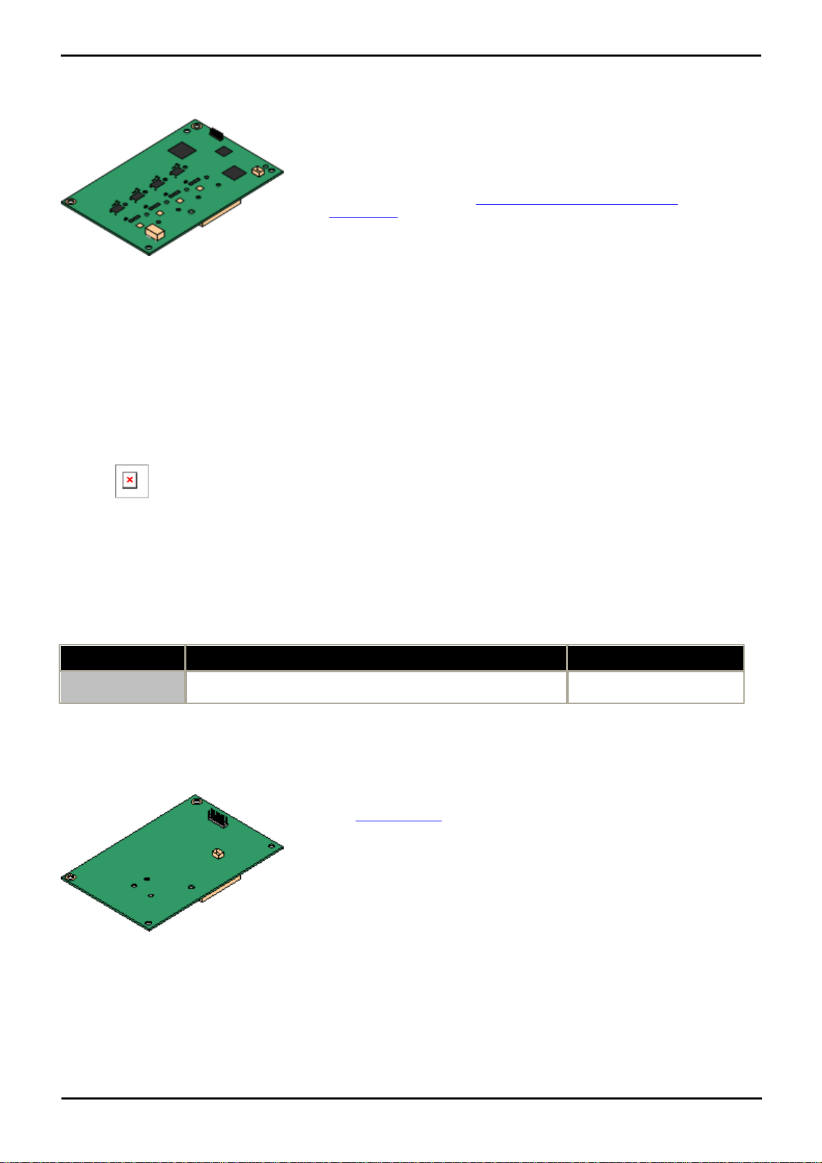
4.4.1 Analog Trunk Card
· Ports/Channels
4 Loop-start analog trunk ports. Connections via the host IP500 base card.
· DTMF, ICLID, Busy tone detection.
· Over-voltage and lightning protection (may still require additional
protection equipment see Lightning Protection/Out-of-Building
Connections.
· DTMF and LD dialing.
· Adjustable echo cancellation (default 16ms). Selectable to Off, 8, 16, 32,
64 and 128 milliseconds.
· Power Failure Port
Regardless of the IP500 card hosting it, during power failure pins 4 and 5
of port 12 are connected to pins 7 and 8. In addition, when fitted to an
IP500 Analog Phone 8 base card, during power failure extension port 8 is
connected to the analog trunk port 12.
· License: No license required.
· Maximum per IP500 Control Unit: 4.
· IP Office Software Level: 4.0+.
Daughter Card Ports (9-12)
The LEDs for ports 9 to 12 of the IP500 base card are used as follows:
· Green on: Card fitted.
· Green flashing: Trunk in use.
· LED 9 is used for daughter card status.
· Red On = Error
· Red Slow Flash = Initializing.
· Red Flash every 5 seconds = Card
okay.
· Red Fast Flash = System shutdown.
Name
Description
Part Number
IPO 500 Trnk Anlg
4 Uni
IP Office 500 Trunk Card Analog 4 Universal
700417405
· Ports/Channels
1 or 2 PRI trunk ports. Each port supports the following PRI line types. On
dual port cards both ports will be the same line type. The line type
selection can be changed using IP Office Manager.
· E1 PRI (30B+D channels per port).
· E1R2 PRI (30B channels per port).
· T1 robbed bit (24B channels per port) or T1 PRI (23B+D channels
per port).
· The required mode can be selected within IP Office Manager by rightclicking on the line icon and selecting Change Universal PRI Card
Line Type and then selecting the required line type.
· Physical trunk connection is via ports 9 and 10 of the host IP500 base
card.
· Port 11 and 12 can be used as test points for connection of test and
monitoring equipment for the adjacent port.
This card can be added to an IP500 base card to provide that card with support for 4 loop-start analog trunks. This card
can be fitted to any IP500 base card except the IP500 Legacy Carrier card and IP500 4-Port Expansion card.
4.4.2 PRI Trunk Cards
This card can be added to an IP500 base card to provide that card with support for PRI trunks. The card is available in
single port or dual port variants.
PARTNER® Version, Installation and Reference Manual Page 56
- Issue 1a (30 January 2010)IP Office Essential Edition
Page 58

System Component Details: Trunk Cards
· Licenses
The IP Office system supports 8 unlicensed B-channels on each IP500 PRIU port fitted. Additional B-channels, up to the capacity of ports installed
and PRI mode selected require IP500 Universal PRI (Additional
Channels) licenses added to the configuration. These additional channels
consume the licenses based on which additional channels are configured as
in-service from port 9 of slot 1 upwards. D-channels are not affected by
licensing.
· Maximum per IP500 Control Unit: 4.
· Software Level: 4.1+.
Daughter Card Ports (9-12)
The LEDs for ports 9 to 12 of the IP500 base card are used as follows:
· Off: No trunk present.
· Green on: Trunk present.
· Green flashing: Trunk in use.
· Red/Green Fast Flash (port 9) or Green
Fast Flash (port 10): Alarm indication
signal (AIS) from the trunk remote end.
· Red with Green Blink (port 9) or Green
Blink (port 10): Port in loopback mode
(set through IP Office System Monitor).
· LED 9 is used for daughter card status.
· Red On = Error
· Red Slow Flash = Initializing.
· Red Flash every 5 seconds = Card
okay.
· Red Fast Flash = System shutdown.
Name
Description
Part Number
IPO 500 TRNK PRI 1 UNI
IP Office 500 Trunk Card Primary Rate 1 Universal
700417439
IPO 500 TRNK PRI 2 UNI
IP Office 500 Trunk Card Primary Rate 2 Universal
700417462
4.5 Expansion Modules
The Essential Edition - PARTNER® Version control unit can support one extension unit as follows:
· Digital Station (DS) module.
or
· Phone module.
4.5.1 Digital Station
IPO 500 Digital Station modules can be used to add additional DS ports to an Essential Edition - PARTNER® Version
system. Note that this requires the IP Office control unit to be configured with an IP Office 500 Upgrade Standard to
Professional license.
The module is referred to as the IPO 500 Digital Station 16.
PARTNER® Version, Installation and Reference Manual Page 57
- Issue 1a (30 January 2010)IP Office Essential Edition
Page 59
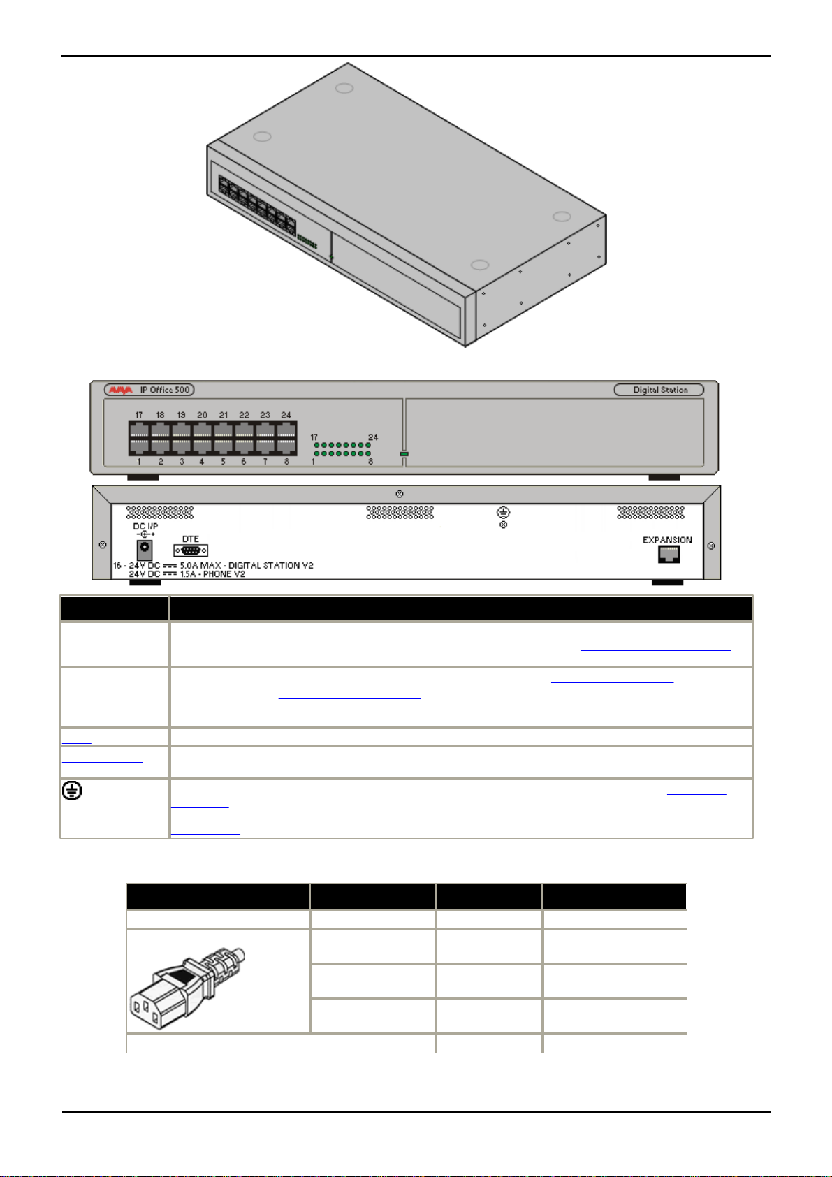
IPO 500 Digital Station Connections
Ports
Description
DC I/P
DC power input port. Used for connection of the power lead from an Avaya earthed 60W external
power supply unit supplied with the expansion module. A locale specific IEC60320 C13 power cord for
the external PSU is required but is not supplied with the module.
DS
RJ45 sockets. Digital Station port. Used for connection of IP Office supported DS phones.
If connected to an out-of-building extension, the connection must be made via additional IROB
barrier devices in addition to the buildings primary protection. The module must also be connected to
a protective ground.
DTE
9-Way D-Type socket. For Avaya use only.
EXPANSION
RJ45 Socket. Used for direct connection to an Expansion port on an IP Office control unit using the
Expansion Interconnect cable supplied with the module.
Protective Ground point. Use of a protective ground is required for all installations, see Grounding
(Earthing). Where the module is connected to analog extensions in another building, an IP Office
Phone Barrier Box V2 (101V) is required at both ends, see Lightning Protection/Out-of-Building
Connections.
Item
Variant
Country
Part number
IPO 500 Digital Station
16 Ports
All
700449499
IEC60320 C13 Power Cord
CEE7/7
Europe
700289762
BS1363
United Kingdom
700289747
NEMA5-15P
America
700289770
IP Office 500Rack Mounting Kit
All
700429202
All expansion modules are supplied with a base software level and should be upgraded to match the core software of the
control unit in the IP Office system.
Expansion modules include an external power supply unit (PSU) and an appropriate interconnect cable. They do not
include a locale specific power cord for the external PSU or any phone extension cables.
PARTNER® Version, Installation and Reference Manual Page 58
- Issue 1a (30 January 2010)IP Office Essential Edition
Page 60
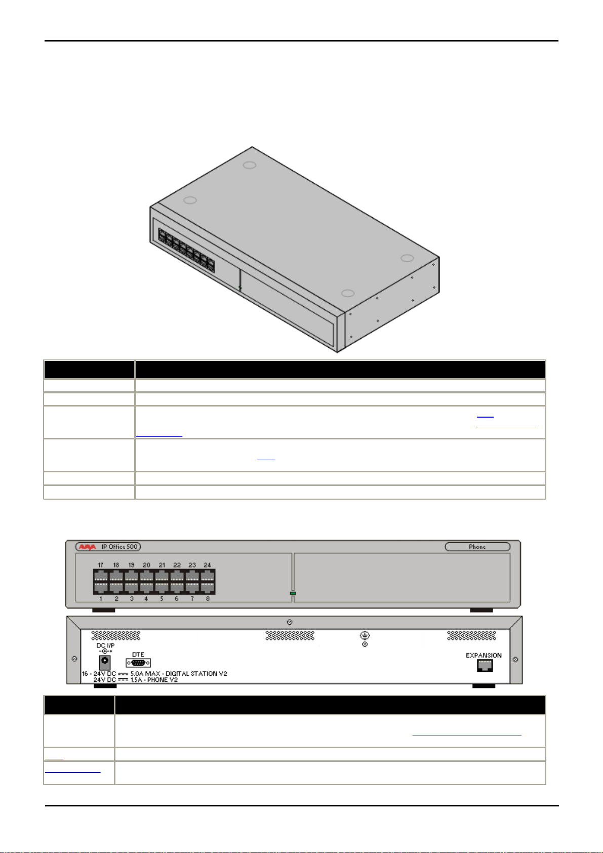
System Component Details: Expansion Modules
Feature
Details
Software Level
IP Office core software level 2.1(36) minimum. Bin file = dvpots.bin.
Included
Power supply unit (see below) and Expansion Interconnect cable.
Power Supply
The module is supplied with a Earthed 3-Pin, 60W external power supply unit. The PSU has an
integral power cord for connection to the module's DC I/P socket. A locale specific IEC60320 C13
power cord for the external PSU is required but is not supplied with the module.
Mounting
The module is designed as a free-standing module that can be stacked on or under other IP Office
modules. The module can be rack
mounted in a 19" rack system using the optional IP Office
500Rack Mounting Kit.
Dimensions
Width: 445mm/17.5". Depth: 245mm/9.7". Height: 71mm/2.8".
Weight
Unboxed: 3.1Kg/6.94lbs. Boxed: 4.4Kg/9.7lbs. (Based on Phone 30 V2)
Ports
Description
DC I/P
DC power input port. Used for connection of the power lead from an Avaya earthed 60W external
power supply unit supplied with the expansion module. A locale specific IEC60320 C13 power cord for
the external PSU is required but is not supplied with the module.
DTE
9-Way D-Type socket. For Avaya use only.
EXPANSION
RJ45 Socket. Used for direct connection to an Expansion port on an IP Office control unit using the
Expansion Interconnect cable supplied with the module.
4.5.2 Phone Module
IPO 500 Phone modules can be used to add additional PHONE ports to an IP Office Partner® Version system. Note that
this requires the IP Office 500 control unit to be configured with an IP Office 500 Upgrade Standard to Professional
license.
The module is referred to as the IPO 500 Phone 16.
IPO 500 Phone Connections
PARTNER® Version, Installation and Reference Manual Page 59
- Issue 1a (30 January 2010)IP Office Essential Edition
Page 61
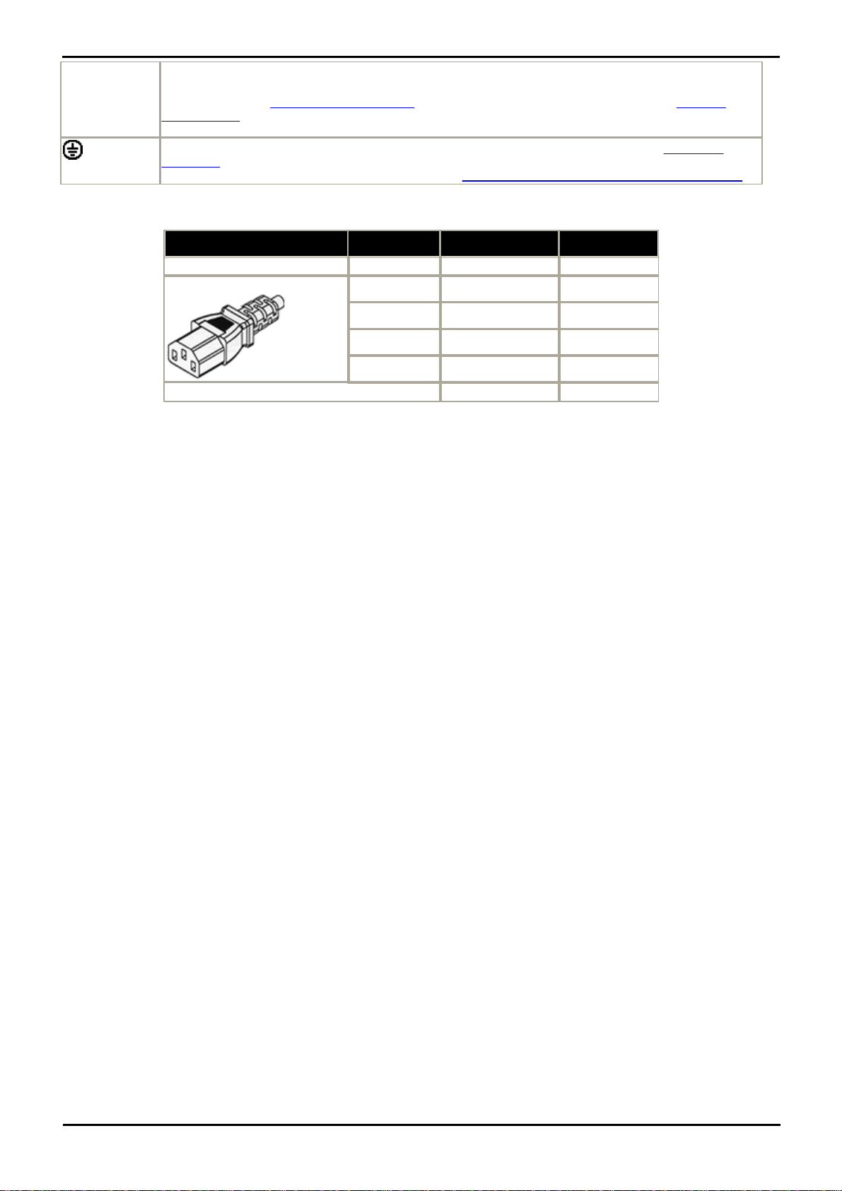
PHONE (front
panel)
RJ45 sockets. Used for connection of analog phones. Intended for two-wire analog phones. For
connection to 4-wire analog phones connection should be via a master socket with ringing capacitors.
If connected to an out-of-building extension, the connection must be made via additional IP Office
Barrier Boxes in addition to the buildings primary protection. The module must also be connected to a
protective ground.
Protective Ground point. Use of a protective ground is required for all installations, see Grounding
(Earthing). Where the module is connected to analog extensions in another building, an IP Office Phone
Barrier Box V2 (101V) is required at both ends, see Lightning Protection/Out-of-Building Connections.
All expansion modules are supplied with a base software level and should be upgraded to match the core software of the
Item
Variant
Country
Part number
IPO 500 Phone
16 Ports
All
700449507
IEC60320 C13 Power Cord
CEE7/7
Europe
700289762
BS1363
United Kingdom
700289747
NEMA5-15P
America
700289770
China
China
700261977
IP Office 500Rack Mounting Kit
All
700429202
control unit in the IP Office system.
Expansion modules include an external power supply unit (PSU) and an appropriate interconnect cable. They do not
include a locale specific power cord for the external PSU or any phone extension cables.
PARTNER® Version, Installation and Reference Manual Page 60
- Issue 1a (30 January 2010)IP Office Essential Edition
Page 62
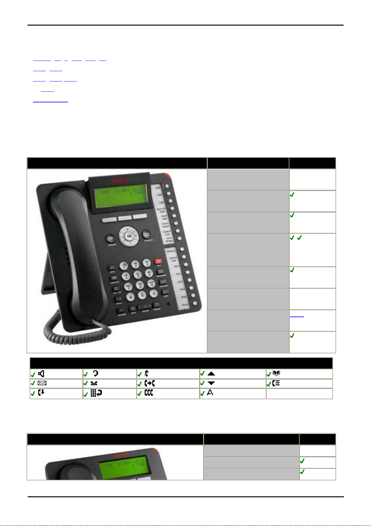
System Component Details: Expansion Modules
1416
Feature
1416
Connects via
DS port.
Programmable Buttons
16
Headset Socket
Hands free Speaker/
Microphone
/
Message Waiting Lamp
Display
4 x 24 Backlit.
Supported Add-Ons
BM32 x 2.
Upgradeable Firmware
Fixed Function Keys
SPEAKER
HEADSET
MUTE
VOLUME UP
CONTACTS
MESSAGE
HOLD
TRANSFER
VOLUME DOWN
CALL LOG
DROP
REDIAL
CONFERENCE
MENU
1408
Feature
1408
Connects via
DS port.
Programmable Buttons
8
Headset Socket
4.6 Telephones
Essential Edition - PARTNER® Version supports the following phones and phone add-ons. Availability may be subject to
local restrictions.
· ETR 34, 18, 6, 34D, 18D, 6D,
· 3910, 3920
· 1403, 1408 1416
· All POTS telephones
· BM32 Buttons
· Digital station connects to the Essential Edition - PARTNER® Version via a DS port.
4.6.1 1416
This phone is supported by the Essential Edition - PARTNER® Version system.
4.6.2 1408
This phone is supported with Essential Edition - PARTNER® Version
PARTNER® Version, Installation and Reference Manual Page 61
- Issue 1a (30 January 2010)IP Office Essential Edition
Page 63
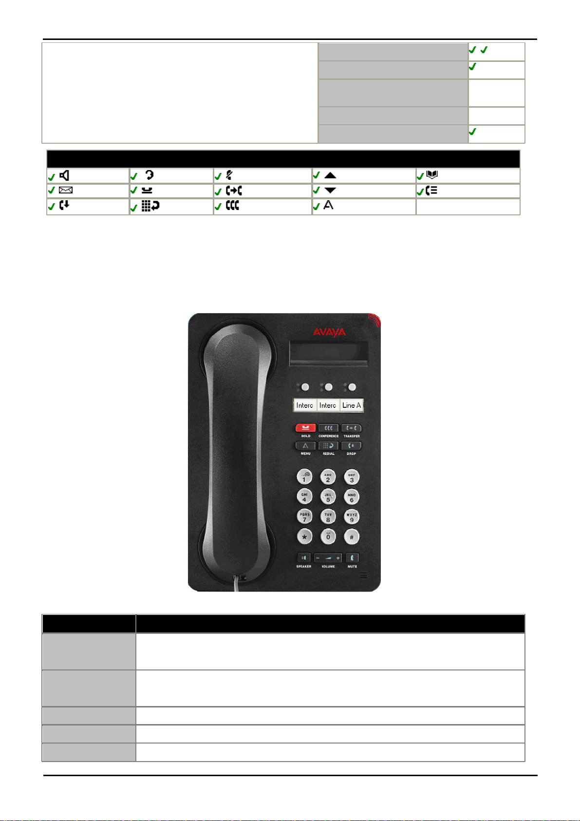
Hands free Speaker/Microphone
/
Message Waiting Lamp
Display
3 x 24
backlit.
Supported Add-Ons
None.
Upgradeable Firmware
Fixed Function Keys
SPEAKER
HEADSET
MUTE
VOLUME UP
CONTACTS
MESSAGE
HOLD
TRANSFER
VOLUME DOWN
CALL LOG
DROP
REDIAL
CONFERENCE
MENU
4.6.3 1403
Name
Description
Message Waiting
Indicator
An illuminated red light in the upper-right corner of your phone indicates you have voicemail
messages waiting. If Visual Alerting is enabled, this light flashes when you receive an incoming
call.
Avaya Menu
Press the A button to access the Avaya menu. Press the A button twice to exit the Avaya menu.
The Avaya menu provides options that allow you to customize phone settings, select the display
language, view network information, and log out.
Redial
Press Redial to dial the last number you dialed.
Hold
Press Hold to put the active call on hold.
Conference
Press Conference to add another party to an existing call.
The 1403 IP telephone is a multi line IP telephone for use with Avaya IP Office. The 1403 IP telephone puts convenient
features and capabilities at your fingertips, including a Conference, Transfer, Hold, and Redial button and a menu of
options and settings to customize your phone.
Not all features described in this user guide may be available on your telephone. If you find that a feature is not
available, contact your system administrator.
PARTNER® Version, Installation and Reference Manual Page 62
- Issue 1a (30 January 2010)IP Office Essential Edition
Page 64
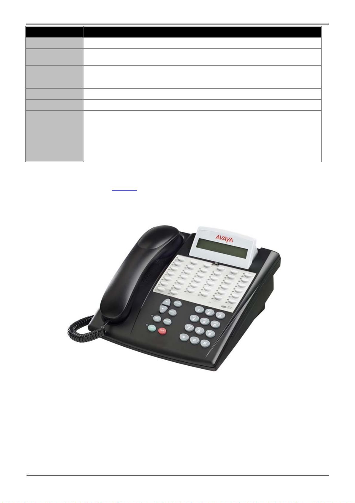
System Component Details: Telephones
Name
Description
Transfer
Press Transfer to transfer a call to another number.
Drop
Press Drop to drop the active call. While on a conference call, press Drop to drop the last person
added to the conference call.
Volume
Press + or - on the volume button while active on the handset or speaker to adjust the volume.
To adjust the volume of the ringer, press + or - on the volume button while the handset and
speaker are inactive.
Mute
Press Mute to mute a call in progress. To take a call off mute, press Mute again.
Speaker
Press Speaker to use the speakerphone. To take a call off speakerphone, lift the handset.
Feature Buttons and
Call/Line
Appearance Buttons
There are 3 buttons that can be programmed by the system administrator as either call/line
appearance buttons or feature buttons. Press a call/line appearance button to make or answer a
call or resume a call on hold. Press a labeled feature button to enable or disable that feature.
Typically, two buttons are administered as call/ line appearance buttons and one button is
administered as a feature button. The feature button provides access to an Avaya call
management system feature that has been administered for your extension. The green LED next
to the feature button indicates if the feature is currently on or off. If the light is on, the feature is
on.
4.6.4 ETR34D
This phone is only supported by an ETR6 card in the Essential Edition - PARTNER® Version system.
All 'Refresh' and 'Euro Style' variants of the phone are supported. An additional analog device using the same extension
number can be connected via the ETR phone AUX socket.
The Essential Edition - PARTNER® Version system supports up to maximum 4 ETR34D handsets (2 per ETR6 module)
The ETR PARTNER® Version telephones have fixed buttons that are already imprinted and line buttons that you can press
to connect to an inside (intercom) or outside line. If a line button is not assigned as an intercom or outside line button,
you can program an extension number or a feature on it. The telephones also have a display, which provides feedback
messages and prompts from the system.
PARTNER® Version, Installation and Reference Manual Page 63
- Issue 1a (30 January 2010)IP Office Essential Edition
Page 65
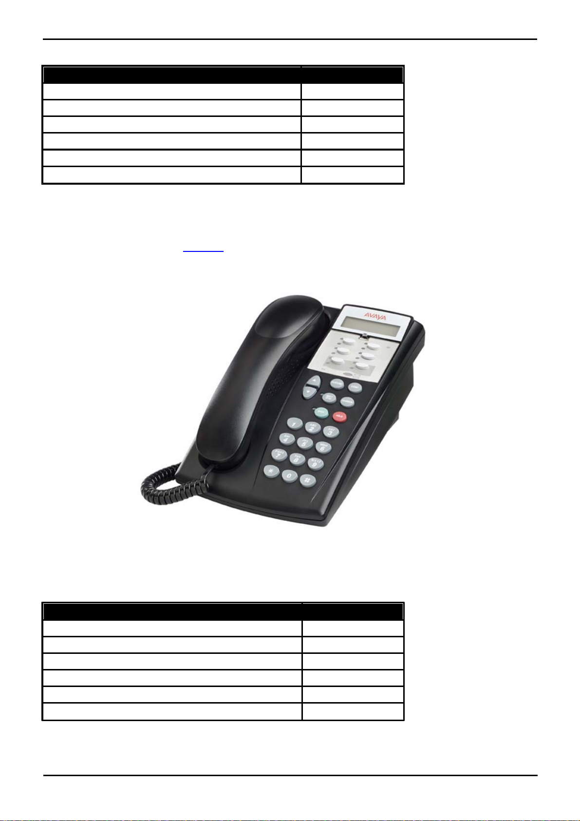
ETR34D Telephone Features
Feature
34
Number of programmable buttons with lights
32
Number of programmable buttons without lights
4
Key mode line button capacity
24
Intercom Buttons
2
Display
Yes
Speakerphone
Yes
Feature
6D
Number of programmable buttons with lights
4
Number of programmable buttons without lights
0
Key mode line button capacity
4
Intercom Buttons
2
Display
Yes
Speakerphone
Yes
4.6.5 ETR6D
This phone is only supported by an ETR6 card in the Essential Edition - PARTNER® Version system.
All 'Refresh' and 'Euro Style' variants of the phone are supported. An additional analog device using the same extension
number can be connected via the ETR phone AUX socket.
The ETR PARTNER® Version telephones have fixed buttons that are already imprinted and line buttons that you can press
to connect to an inside (intercom) or outside line. If a line button is not assigned as an intercom or outside line button,
you can program an extension number or a feature on it. The telephones also have a display, which provides feedback
messages and prompts from the system.
ETR6D Telephone Features
PARTNER® Version, Installation and Reference Manual Page 64
- Issue 1a (30 January 2010)IP Office Essential Edition
Page 66
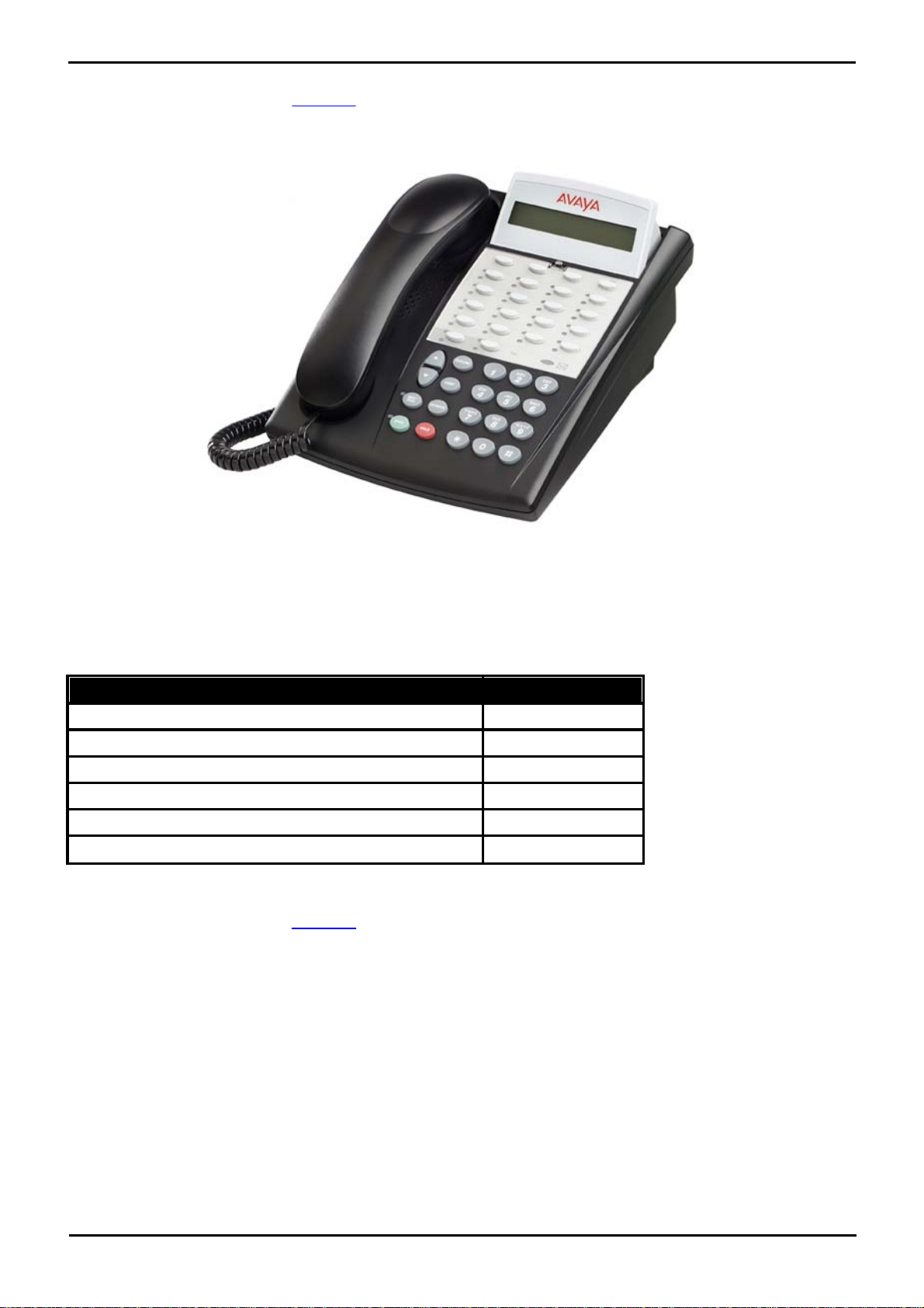
System Component Details: Telephones
Feature
18D
Number of programmable buttons with lights
16
Number of programmable buttons without lights
4
Key mode line button capacity
16
Intercom Buttons
2
Display
Yes
Speakerphone
Yes
4.6.6 ETR18D
This phone is only supported by an ETR6 card in the Essential Edition - PARTNER® Version system.
All 'Refresh' and 'Euro Style' variants of the phone are supported. An additional analog device using the same extension
number can be connected via the ETR phone AUX socket.
The ETR PARTNER® Version telephones have fixed buttons that are already imprinted and line buttons that you can press
to connect to an inside (intercom) or outside line. If a line button is not assigned as an intercom or outside line button,
you can program an extension number or a feature on it. The telephones also have a display, which provides feedback
messages and prompts from the system.
ETR18D Telephone Features
4.6.7 ETR34
This phone is only supported by an ETR6 card in the Essential Edition - PARTNER® Version system.
All 'Refresh' and 'Euro Style' variants of the phone are supported. An additional analog device using the same extension
number can be connected via the ETR phone AUX socket.
The ETR PARTNER® Version telephones have fixed buttons that are already imprinted and line buttons that you can press
to connect to an inside (intercom) or outside line. If a line button is not assigned as an intercom or outside line button,
you can program an extension number or a feature on it.
PARTNER® Version, Installation and Reference Manual Page 65
- Issue 1a (30 January 2010)IP Office Essential Edition
Page 67
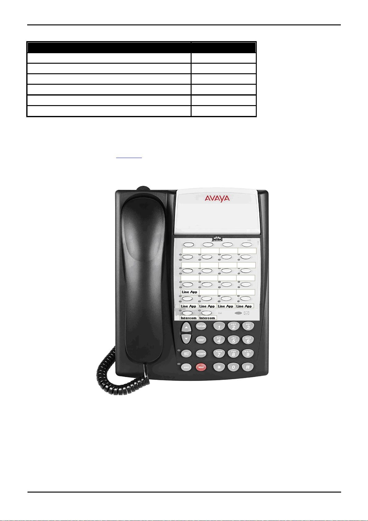
ETR34 Telephone Features
Feature
Number of programmable buttons with lights
32
Number of programmable buttons without lights
4
Key mode line button capacity
24
Intercom Buttons
2
Display
No
Speakerphone
Yes
4.6.8 ETR18
This phone is only supported by an ETR6 card in the Essential Edition - PARTNER® Version system.
All 'Refresh' and 'Euro Style' variants of the phone are supported. An additional analog device using the same extension
number can be connected via the ETR phone AUX socket.
The ETR PARTNER® Version telephones have fixed buttons that are already imprinted and line buttons that you can press
to connect to an inside (intercom) or outside line. If a line button is not assigned as an intercom or outside line button,
you can program an extension number or a feature on it.
PARTNER® Version, Installation and Reference Manual Page 66
- Issue 1a (30 January 2010)IP Office Essential Edition
Page 68
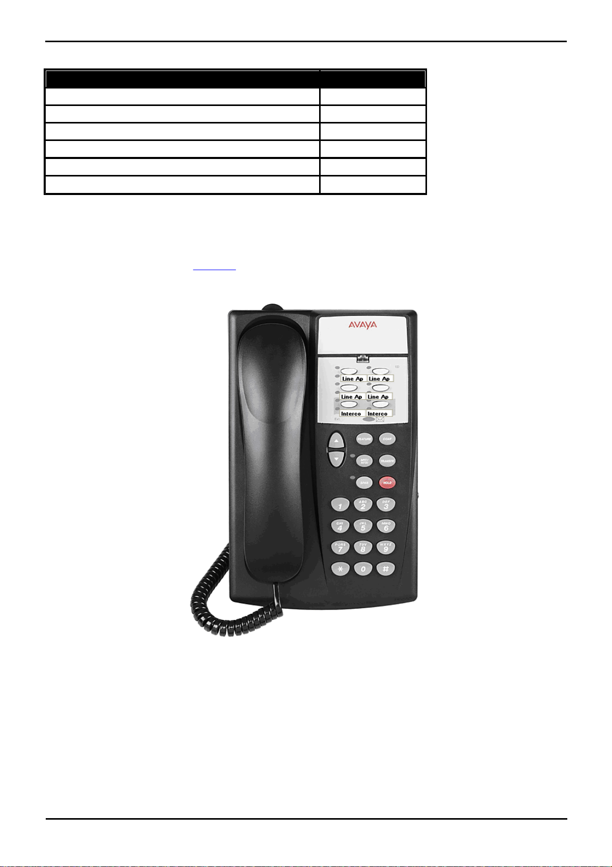
System Component Details: Telephones
Feature
Number of programmable buttons with lights
16
Number of programmable buttons without lights
4
Key mode line button capacity
16
Intercom Buttons
2
Display
No
Speakerphone
Yes
ETR18 Telephone Features
4.6.9 ETR6
This phone is only supported by an ETR6 card in the Essential Edition - PARTNER® Version system.
All 'Refresh' and 'Euro Style' variants of the phone are supported. An additional analog device using the same extension
number can be connected via the ETR phone AUX socket.
The ETR PARTNER® Version telephones have fixed buttons that are already imprinted and line buttons that you can press
to connect to an inside (intercom) or outside line. If a line button is not assigned as an intercom or outside line button,
you can program an extension number or a feature on it.
PARTNER® Version, Installation and Reference Manual Page 67
- Issue 1a (30 January 2010)IP Office Essential Edition
Page 69
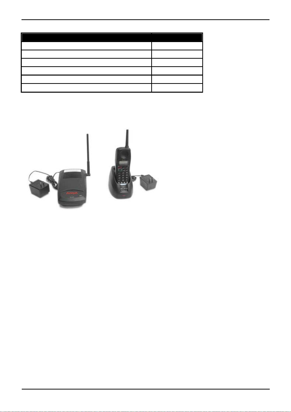
ETR6 Telephone Features
Feature
Number of programmable buttons with lights
4
Number of programmable buttons without lights
0
Key mode line button capacity
4
Intercom Buttons
2
Display
No
Speakerphone
Yes
4.6.10 3910
This single station DECT phone is supported on an IP 500v2 control unit running in Partner® Version mode. The base
station uses an ETR port for connection to the IP Office. This phone is no longer available from Avaya and has been
superseded by the 3920.
4.6.11 3920
The Avaya 3920 is a single station DECT phone wireless telephone, designed specifically for small businesses
Utilizing next-generation digital technology (DECT 6.0), the Avaya 3920 wireless telephone offers high quality voice
communication. DECT, unlike other wireless technologies, uses a dedicated frequency that prevents interference from
other devices and delivers increased coverage in warehouse and campus-like environments.
* Coverage area depends on building construction and environmental conditions.
The base station uses an ETR port for connection to Essential Edition - PARTNER® Version.
PARTNER® Version, Installation and Reference Manual Page 68
- Issue 1a (30 January 2010)IP Office Essential Edition
Page 70
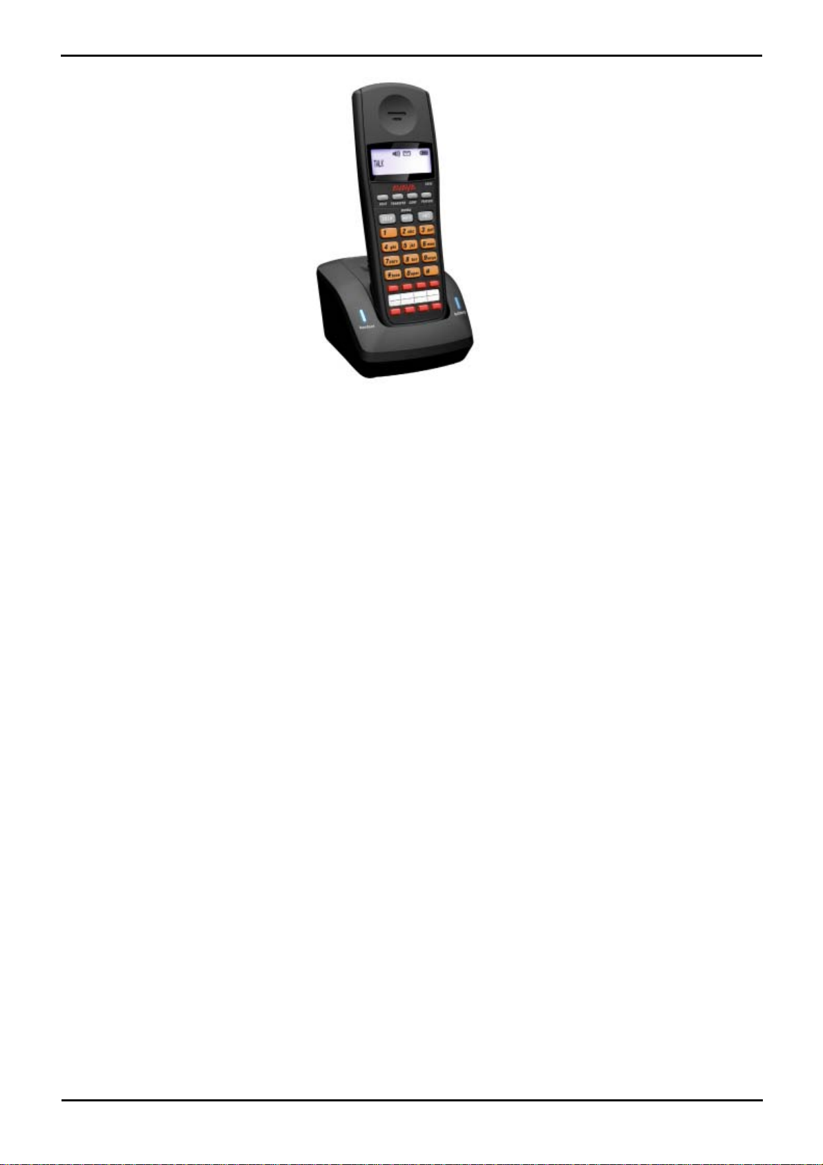
System Component Details: Telephones
4.6.12 POTS
Essential Edition - PARTNER® Version systems support most types of analog phone.
There are differences in behavior between ETR6 POTs and PHONE/Combination POTs that should noted:
· ETR6 POTs are defined as POTs directly connected to the ETR6 module and not to the AUX jack on the back of an ETR
digital telephone. PHONE/Combination POTs are POTs connected to PHONE or Combination system modules.
· PHONE/Combination POTs cannot have line appearances whilst ETR6 POTs can. ETR6 POTs having line appearances is
consistent with PARTNER® ACS operation.
· PHONE/Combination POTs ring with ring patterns consistent with IP Office whilst ETR6 POTs ring with ring patterns
consistent with PARTNER® ACS:
· Intercom calls to PHONE/Combination POTs are one long ring while on ETR6 POTs, they are one long ring
followed immediately by one short ring.
· Outside calls on PHONE/COMBO POTs are one very long ring whilst on ETR6 POTs they are just one long ring.
· Transferred calls on PHONE/COMBO POTs are the same ring as the base call type, inside or outside, while on
ETR6 POTs they are one long ring followed immediately by two short rings.
· Returning held calls on PHONE/Combination POTs are three short rings whilst on ETR6 POTs they are one long
ring followed immediately by two short rings.
· Returning parked calls on PHONE/Combination POTs ring with the base call ringing pattern whilst on ETR6 POTs
they ring with the same ring as the returning held call.
· ETR6 POTs cannot place calls on hold for extended periods like PHONE/Combination POTs. This is consistent with
PARTNER® ACS POT behavior. If a call is placed on hold and the ETR6 POT user hangs up, the call immediately returns
and rings with the returning held call ringing pattern described above.
· The PE Automatic Line Selection feature applies to ETR6 POTs whilst it does not apply to PHONE/Combination POTs.
When a PHONE/Combination POTs user dials 9 to obtain an outside line, it looks for an available line starting at line one
and progressing upwards. When a ETR6 POTs user dials 9 to obtain an outside line, it uses the ALS programming to
select an available line potentially skipping some lines.
· Call Waiting Tone is consistent between ETR6 POTs and PHONE/Combination POTs, which is one short beep of tone.
This is inconsistent (but acceptable) with PARTNER® ACS which is two short beeps of tone.
PARTNER® Version, Installation and Reference Manual Page 69
- Issue 1a (30 January 2010)IP Office Essential Edition
Page 71
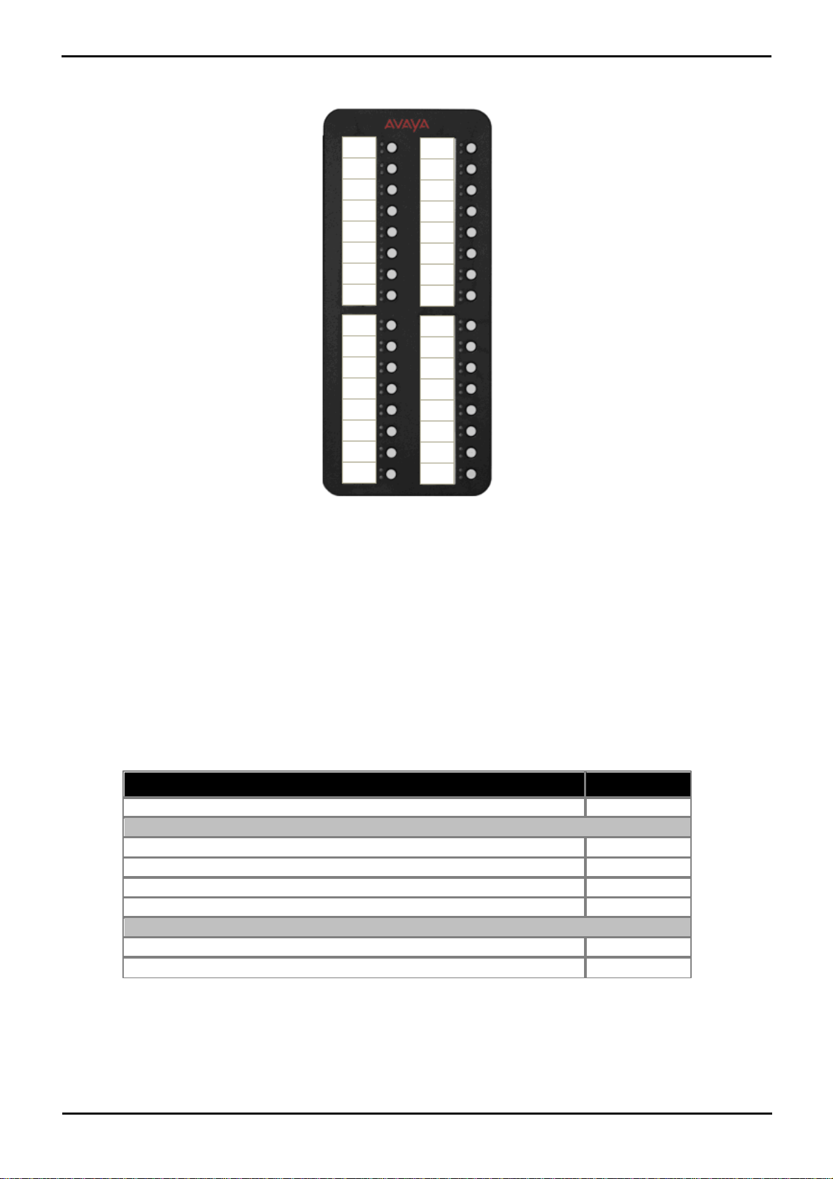
4.6.13 Phone Add-Ons
Item
Part number
BM32 BUTTON MODULE
700415573
Accessories
1600 SERIES BM32 CABLE - REPLACEMENT
700415581
1600 SERIES BM32 BOND BRIDGE - REPLACEMENT
700415599
1616/BM32 PLASTIC LABEL COVERS (20) – REPLACEMENT
700415672
1600 SERIES BM32 FLIP STAND - REPLACEMENT
700432800
Paper Labels
1616/BM32 PAPER DESI LABELS - PACKAGE OF 50 LABELS (8.5" x 11")
700415656
1616/BM32 PAPER DESI LABELS - PACKAGE OF 50 LABELS (A4)
700434236
The 1416 phone supports button modules which provided the phone with additional programmable buttons.
The number of button modules supported per phone and per system are as follow:
· DBM32: (1416)
Up to 32 DBM32s supported (32 buttons each, up to 1024 buttons).
The maximum combined number of buttons per system is 512, regardless of whether the buttons are programmed or
not.
This add on provides an additional 32 twin-LED programmable buttons for 1416 phones. The BM32 does not require its
own power supply connection, instead it draws power from the phone to which it is connected.
· Only two BM32 units can be connected in a chain from a single 1416. Up to three 1416 telephones with BM32s are
supported, i.e. 6 BM32s.
· To support a BM32 the phone must be powered by an individual 1600 Series Power Adapter.
· Up to a maximum of 16 BM32 units are supported on the whole IP Office system.
· The BM32 buttons cannot be used for appearance functions such as call and line appearances.
PARTNER® Version, Installation and Reference Manual Page 70
- Issue 1a (30 January 2010)IP Office Essential Edition
Page 72
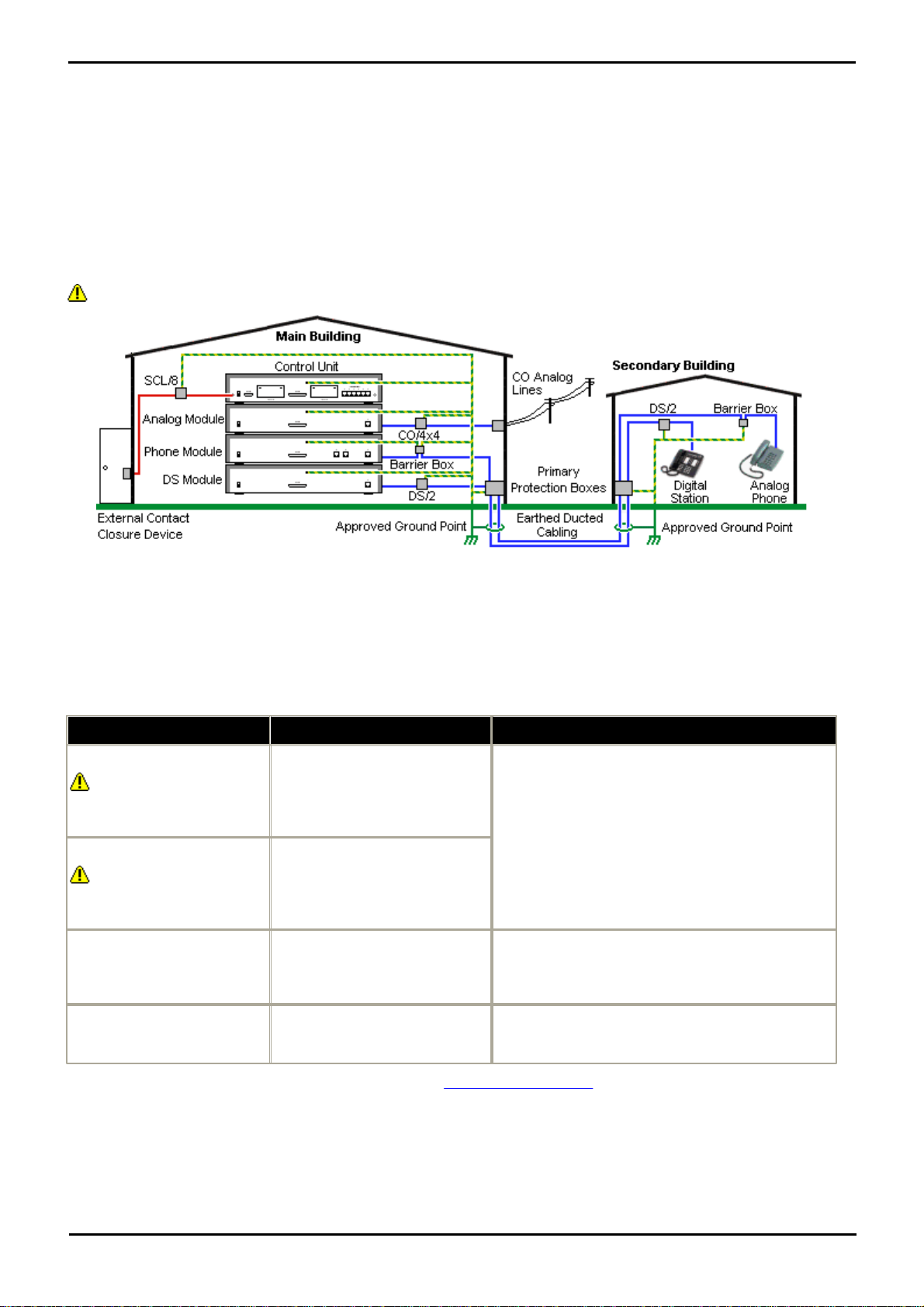
System Component Details: Telephones
Connection Type
Protection Device Type
Requirement
DS Phone Extensions
Digital Station Expansion
module DS ports only.
ITWLinx towerMAX DS/2
Supports up to 4 connections.
(This device was previously
referred to as the Avaya 146E).
· Connection from the expansion module to the
phone must be via a surge protector at each end
and via the primary protection point in each
building.
· The IP Office expansion module and control unit
and IROB devices must be connected to the
protective ground point in their building.
· The between building connection must be via
earthed ducting, preferable underground. The
cable must not be exposed externally at any point.
Analog Phone Extensions
Phones Expansion module (
POT or PHONE) ports only.
IP Office Barrier Box
Supports a single connection.
Maximum of 16 on any expansion
module.
Analog Trunks
ITWLinx towerMAX CO/4x4
Supports up to 4 two-wire lines.
(This device was previously
referred to as the Avaya 146C).
For locations where the risk of lightning strikes is felt
to be high, additional protection of incoming analog
trunks is recommended.
External Output Switch
ITWLinx towerMAX SCL/8
(This device was previously
referred to as the Avaya 146G)
Connections from an IP Office Ext O/P port to an
external relay device must be via a surge protector.
4.7 Out of Building Telephone Installations (COPY)
The following are the only supported scenarios in which wired extensions and devices outside the main building can be
connected to the IP Office system. In these scenarios, additional protection, in the form of protective grounding and
surge protectors, must be fitted.
The fitting of additional protection does not remove the risk of damage. It merely reduces the chances of damage.
Cabling Requirements
· Cables of different types, for example trunk lines, extensions, ground and power connections, should be kept separate.
· All cabling between building should be enclosed in grounded ducting. Ideally this ducting should be buried.
· A Primary Protection Box must be provided at the point where the cables enter the building. This should be three point
protection (tip, ring and ground). Typically this would be gas tube protection provided by the local telephone company.
The ground wire must be thick enough to handle all the lines being affected by indirect strike at the same time.
* The towerMAX range of devices are supplied by ITWLinx (http://www.itwlinx.com).
PARTNER® Version, Installation and Reference Manual Page 71
- Issue 1a (30 January 2010)IP Office Essential Edition
Page 73
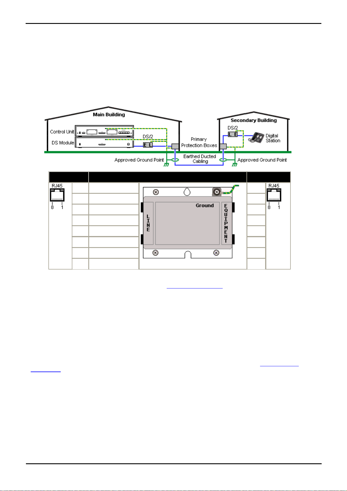
4.7.1 DS Phones
LINE
Signal
EQUIPMENT
1
Not used.
1
2
Not used.
2
3
Ring II (Optional)
3
4
Ring I
4
5
Tip I
5
6
Tip II (Optional)
6
7
Not used.
7
8
Not used.
8
When digital phone extensions are required in another building, additional In-Range Out-Of-Building (IROB) protective
equipment must be used. For phones connected to IP Office DS ports, the supported device supplied by ITWLinx is a
towerMAX DS/2* module. This IROB device was previous badged by Avaya as the 146E IROB.
The protection device should be installed as per the instructions supplied with the device. The ground points on the IP
Office control unit and the DS modules must be connected to a protective ground using 18AWG wire with a green and
yellow sleeve.
Typically the IROB
2 RJ45 EQUIPMENT ports are straight through connected to the 2 RJ45 LINE ports. This allows existing RJ45 structured
cabling, using pins 4 and 5, to be used without rewiring for up to two DS connection. However each of these ports can be
used to connect a second extension using pins 3 and 6.
* The towerMAX range of devices are supplied by ITWLinx (http://www.itwlinx.com).
4.7.2 Analog Phone Barrier Box
Where analog phone extensions are required in another building, additional protective equipment must be used, in the
form of IP Office Phone Barrier Boxes and protective earth connections.
· The correct IP Office specific barrier boxes must be used. These modules have been designed specifically for the
signalling voltages used by the IP Office system:
· Only the IP Office Phone Barrier Box V2 should be used.
· No other type of analog phone barrier box should be used.
· Where more than 3 barrier boxes are required in a building, they must be rack mounted using a Barrier Box rack
mounting kit.
· A maximum of 16 barrier boxes can be used with any Phone module.
· CAUTION: PHONE (POT) ports on the front of control units must not be used for extensions that are external to the
main building.
PARTNER® Version, Installation and Reference Manual Page 72
- Issue 1a (30 January 2010)IP Office Essential Edition
Page 74
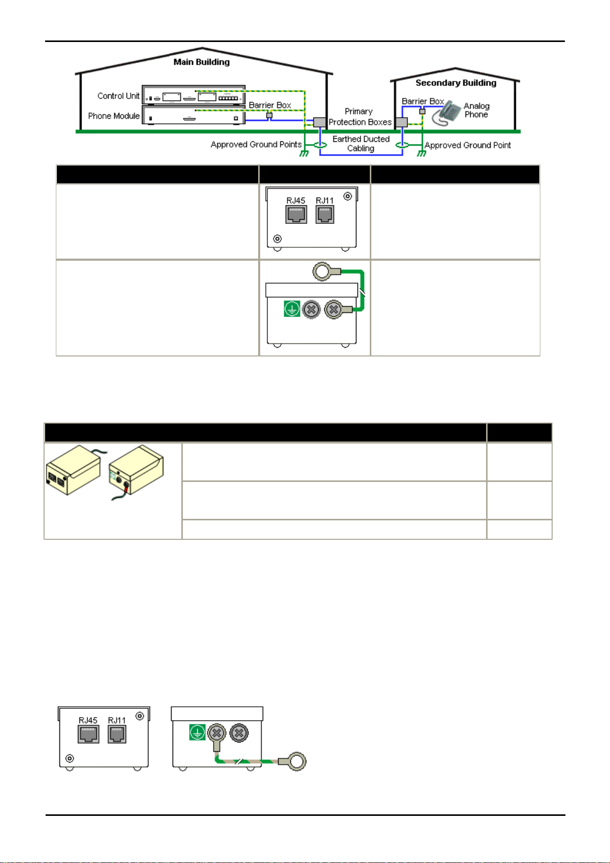
System Component Details: Out of Building Telephone Installations (COPY)
Main Building
Barrier Box
Secondary Building
· RJ11: Connect to PHONE (POT) port on the
Phone module using cable supplied with the
barrier box.
· RJ45: Connect to the secondary building
barrier box via primary protection in both
buildings.
· RJ11: Connect to analog phone.
Cable not supplied.
· RJ45: From main building via
primary protection in both buildings.
· Center Screw: Connect to main building
protective ground (or ground terminal of
Barrier Box Rack Mounting Kit). Use 18AWG
(minimum) wire with a green and yellow
sleeve.
· Right-Hand Screw: Connect to ground point
on Phone module using ground cable supplied
with barrier box.
· Center Screw: Connect to main
building protective ground. Use
18AWG (minimum) wire with a green
and yellow sleeve.
· Right-Hand Screw: Not used.
IP Office Barrier Boxes
Part number
IP Office 500 Phone Barrier Box (81V)
Use with Phone V1 module. Includes an RJ45 to RJ11 cable and a
functional earth lead.
700293897
IP Office 500 Phone Barrier Box V2 (101V)
Use with Phone V2 module. Includes an RJ45 to RJ11 cable and a
functional earth lead.
700385495
Barrier Box Rack Mounting Kit
700293905
Wires from external telephone going directly to the barrier boxes must be kept apart, that is not routed in the same
bundle:
4.7.3 Rack Mounting Barrier Boxes
Where more than 3 Phone Barrier Boxes are used they must be rack mounted. The Barrier Box Rack Mounting Kit (Part
number 700293905) supports up to 8 Phone Barrier Boxes.
1.Unscrew the two screws arranged diagonally at the front of each barrier box and use these same screws to reattach
the barrier box to the rack mounting strip.
2.Each barrier box is supplied with a solid green ground wire connected to its functional ground screw. Remove and
discard this wire. Connect a green/yellow ground wire to the protective earth screw in the center of the Point on the
back of the Barrier Box.
PARTNER® Version, Installation and Reference Manual Page 73
- Issue 1a (30 January 2010)IP Office Essential Edition
Page 75
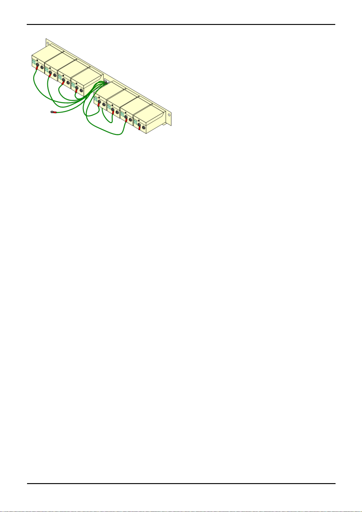
3.The rack mounting strip has threaded M4 earthing pillars. Connect the free end of the barrier box ground wire, using
M4 washers and nuts, to the earthing pillar on that side of the rack mounting strip.
4.Using 14AWG wire with green and yellow sleeve, connect one of the earthing pillars to the buildings protective earth.
5.Using 14AWG wire with green and yellow sleeve, connect the other earthing pillar to the Phone module.
6.Ensure that the following wires are not routed together in the same bundle:
· Earth lead from the barrier box to the Phone 8/16/32.
· Internal wires, e.g. wires going directly to the Phone 8/16/32.
· Wires from external telephone going directly to the barrier boxes.
PARTNER® Version, Installation and Reference Manual Page 74
- Issue 1a (30 January 2010)IP Office Essential Edition
Page 76

System Component Details: Out of Building Telephone Installations (COPY)
4.8 Associated Applications
This section outlines the PC applications supported by Essential Edition - PARTNER® Version. These are just outlines, for
full details refer to the specific installation manuals for those applications and to the IP Office Technical Bulletins.
Note: The use of Windows 2000 operating systems is no longer tested or supported with Essential Edition -
PARTNER® Version applications
The following Windows applications are used to program and maintain an IP Office system. They run on PCs connected to
the IP Office system via its LAN interface. These applications are all provided on the IP Office Administrator Applications
CD and don't require any licenses.
Typically all these applications would be installed onto a single PC (usually a laptop) in order to ensure that each is
available on site if required. Due to the nature of the applications, this should be a secure PC.
· IP Office Manager
This tool is used to access all parts of the Essential Edition - PARTNER® Version configuration. Manager is also
used to upgrade the software files used by the system. When running is can also act as the TFTP server from
which upgradable Avaya phones can request new software.
· Embedded Voicemail
Also called Integral Voicemail, this application is supported by the IP Office 500v2 control unit. It is pre-installed
on the SD Card to store messages and prompts. Embedded Voicemail supports basic voicemail mailbox operation,
simple auto-attendants and hunt group announcements.
· System Status Application
This application can be used to inspect the current status of Essential Edition - PARTNER® Version lines and
extensions and to view records of recent alarms and events. It runs as a Java application.
· TAPI/Devlink
Provides a real-time event stream in addition to the SMDR interface provided in Essential Edition - PARTNER®
Version SMDR. The real-time event stream takes the form of a call record, which is issued whenever the state of
any endpoint of a call changes (typically there are two end points on a call, but for some circumstances, such as
conference calls or intruded calls there may be more)
· Monitor (SysMon)
Monitor is a tool that can show a trace of all activity on the IP Office system in detail. As a consequence,
interpretation of Monitor traces requires a high-level of data and telephony protocol knowledge. Despite that
however, all IP Office installers and maintainers need to understand how to run Monitor when necessary as Avaya
may request copies of Monitor traces to resolve support issues.
4.8.1 Voicemail
Key features are:
• Does not require a license key.
• Maximum Message Length = 120 seconds for any message.
• Maximum of 4 Simultaneous Users
• Supports basic voicemail email and customization.
• Pin code
• Ringback
• Voicemail On/Off
• Email address
• Voicemail email on/off
User, Group and Mailbox Names
The voicemail application creates mailboxes based on the user and hunt group names allocated using the Essential
Edition - PARTNER® Version Manager application. Whenever either the voicemail server or the Control Unit restart,
new mailboxes are created for any new names found.
This method of operation has the following consequences:
· Mailboxes are based on names: For all users and groups, if their name is changed, they may no longer be
associated with their former mailbox.
· Voicemail is case sensitive: If a mailbox or start point name is entered incorrectly within a Manager or
Voicemail Pro, the intended operation will not occur and the call may be disconnected.
· Voicemail removes spaces at the end of mailbox names: If spaces are left at the end of a mailbox user's
name within Manager, when Voicemail creates the directory the space at the end of the name will be dropped.
When this occurs the mailbox cannot be found as there is a miss-match between the user name and directory.
The default configuration for Essential Edition - PARTNER® Version allows almost immediate voicemail operation once the
voicemail server is running. The IP Office default settings are:
• Voicemail on for each user and hunt group on the IP Office.
PARTNER® Version, Installation and Reference Manual Page 75
- Issue 1a (30 January 2010)IP Office Essential Edition
Page 77
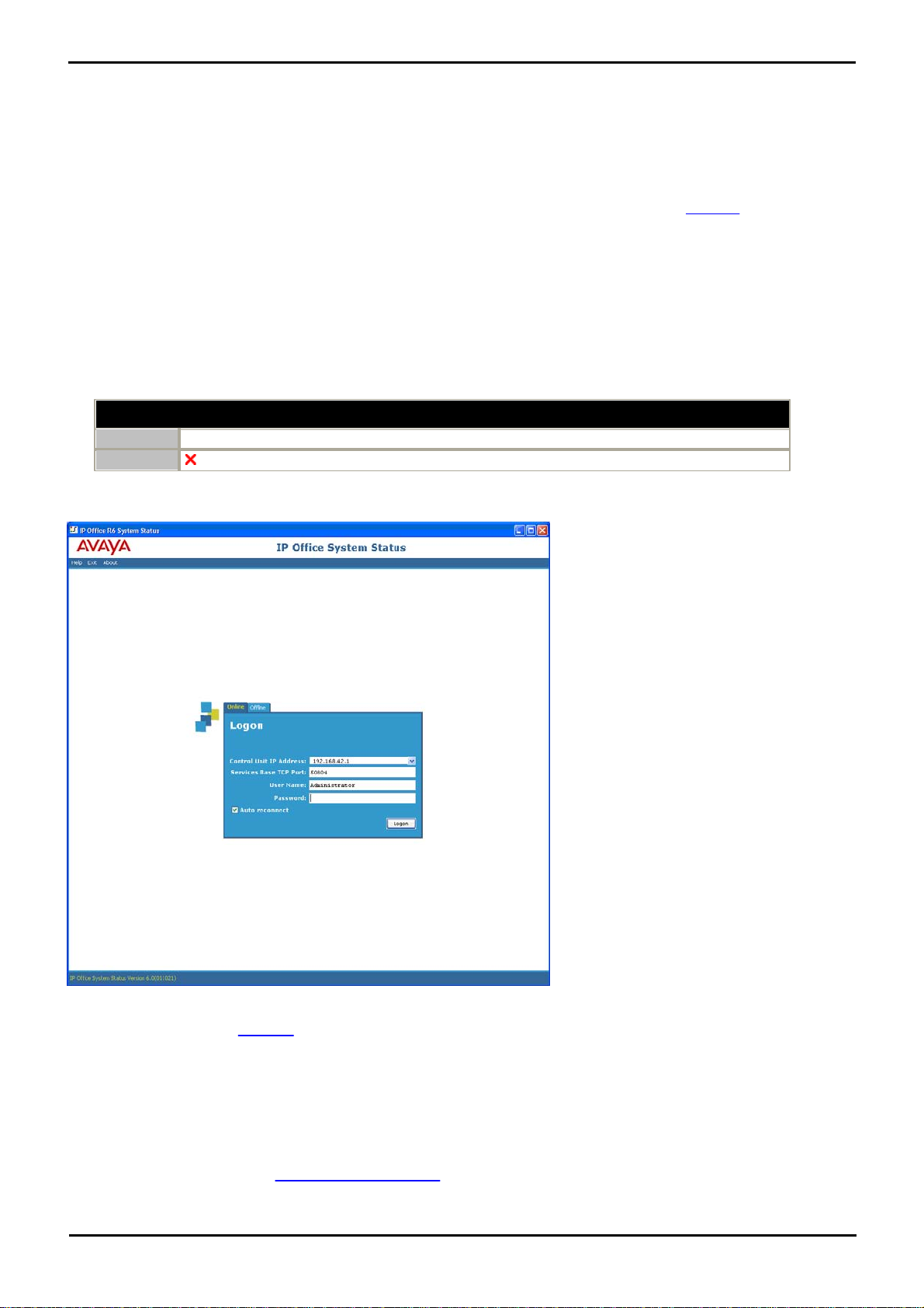
• No Voicemail Code set for any mailboxes. Until a code is entered for a mailbox, it can only be accessed from the
Details
DVD
<%APPSDVD%>
License
No license required.
user's own extension.
• No Voicemail Email or Voicemail Help operational.
• No Voicemail Reception for user mailboxes.
• Whilst hunt group mailboxes are created and used by default, there is no default method for accessing them. A
method for accessing each hunt group mailbox should be programmed. See "Hunt Group Voicemail" on page 36.
A range of settings and controls are accessible through the Essential Edition - PARTNER® Version Manager Application to
configure the voicemail operation.
4.8.2 System Status Application (SSA)
This tool provides a wide range of information about the current status of an Essential Edition - PARTNER® system. It
includes available resources and components within the system. This includes details of current call in progress. Details of
the number of alarms are recorded and the time date of the most recent alarms.
When required for diagnostics escalation SSA is able to take a snap shot image of the IP Office system status including a
copy of its current configuration. Use of SSA requires an IP Office service user name and password that has been
configured for System Status access in the IP Office security settings.
SSA is pre-installed on the system Avaya SD memory card and can be run by selecting File | Advanced | System
Status from the main menu
Respond to the password request.
Further SSA information is available in this document.
4.8.3 Monitor
Monitor (also know as System Monitor) is a tool that can show all activity on the IP Office system in great detail. As a
consequence, interpretation of Monitor traces requires a high-level of data and telephony protocol knowledge. However,
all IP Office installers and maintainers must understand how to run Monitor when necessary as Avaya may request copies
of Monitor traces to resolve support issues.
For IP Office 4.0 and higher, the System Status Application has been added to provide more easily interpreted
information than is provided by Monitor.
PARTNER® Version, Installation and Reference Manual Page 76
- Issue 1a (30 January 2010)IP Office Essential Edition
Page 78
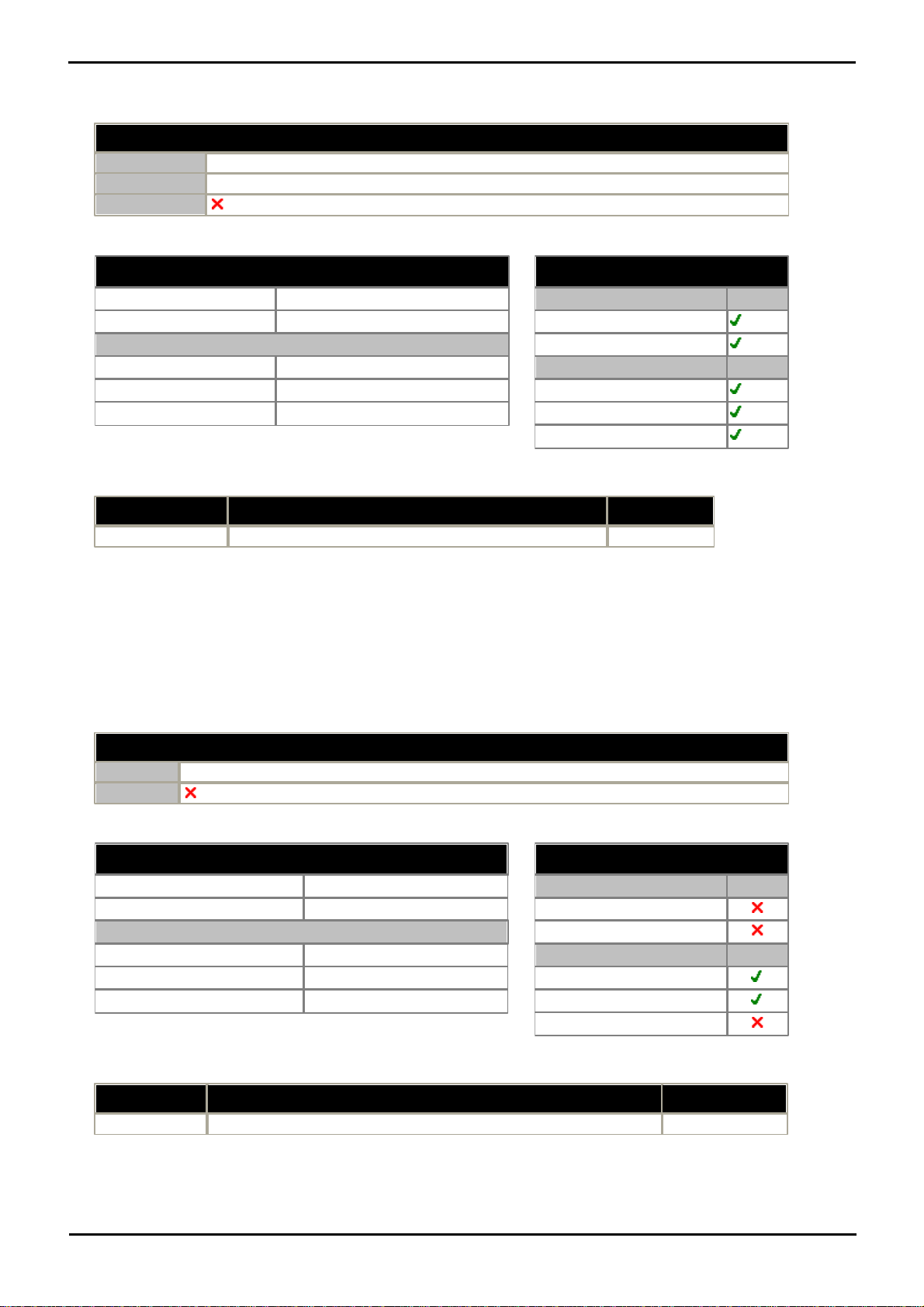
System Component Details: Associated Applications
Details
DVD
<%APPSDVD%>
Languages
English only.
License
No license required.
Minimum PC Requirements
RAM
128MB
Hard Disk Free Space
10GB
Processor:
- Pentium
PIII 800MHz
- Celeron
Celeron 3 800Mhz
- AMD
Athlon B 650MHz
Operating System Support
Server OS:
2003 Server
2008 Server
Client OS:
XP Professional
Vista
Windows 7
Component
Location - %ProgramFiles%\Avaya\IP Office\
Ports
System Monitor
Monitor\sysmonitor.exe
UDP 50794.
Details
DVD
<%APPSDVD%>
License
Optional. Licenses are required for 3rd party TAPI mode operation.
Minimum PC Requirements
RAM
64MB
Hard Disk Free Space
50MB
Processor:
- Pentium
PIII 800MHz
- Celeron
Celeron 3 800Mhz
- AMD
Athlon B 65-0MHz
Operating System Support
Server OS:
2003 Server
2008 Server
Client OS:
XP Professional
Vista
Windows 7
Component
Location - %ProgramFiles%\Avaya\IP Office\
Ports
TAPI2
TAPI\tspi2w.tsp
UDP 50797.
· Two versions of Monitor are included in the IP Office Admin applications suite, one for IP Office 4.0 systems and
one for pre-4.0 IP Office systems. Care should be taken to ensure that the correct version is used when
monitoring an IP Office system.
PC Requirements
Ports
4.8.4 TAPI
IP Office TAPI is a client PC application that allows TAPI compliant applications to interact with the Essential Edition PARTNER® Version. The IP Office TAPI software can be used in one of two modes, depended on whether it is licensed or
not. The same software is installed in either case with the licenses, if any, being entered in the Essential Edition PARTNER® Version system configuration.
· 3rd Party TAPI
In this licensed mode, TAPI software can be used to control call function on multiple user extension. This mode is
used with CTI Developer applications.
PC Requirements:
Ports
PARTNER® Version, Installation and Reference Manual Page 77
- Issue 1a (30 January 2010)IP Office Essential Edition
Page 79
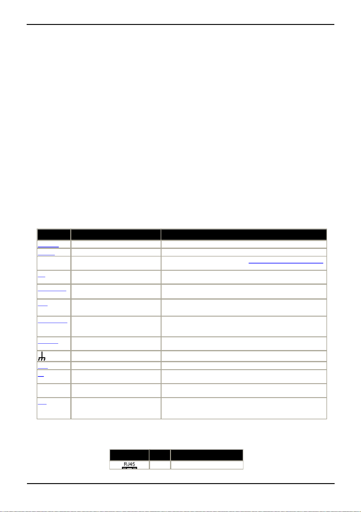
· DevLink
Port
Found on
Description
ANALOG
ATM4 Trunk card (x4).
Used for the connection of external analog trunks.
AUDIO
Rear of IP Office control unit.
Used for input of an external music on hold source.
Digital
Station
ATM4 Combination base card (x2)
Connection of Avaya digital station phones supported by IP Office
DS
Digital Station expansion modules
(x16).
Connection of digital phones
RS232/DTE
All control units (x1).
All expansion modules (x1).
Used for control unit maintenance under Avaya guidance. On
expansion modules not used.
ETR
ETR (Enhanced Tip and Ring),
provided by the ETR6 base card.
Used for the connection of DTMF analog phone devices and Avaya
ETR phones.
EXPANSION
All control units (x various).
All expansion modules except
WAN3 (x1).
Used for interconnection of external expansions modules and
control units.
EXT O/P
All control units (x1).
Used to control external relay systems. The port provides two
switchable (on, off and pulse) controls.
All modules (x1).
Used for connection of functional or protective ground if required.
LAN
All control units (x various).
10/100Mbps Ethernet LAN ports.
PF
Analog Trunk expansion module
(x2).
Analog power fails ports.
PHONE
(POT)
Phones expansion modules (x8/
x16).
Analog phone extension ports. On older units these ports are
labeled as POT ports.
PRI
Single PRI trunk cards (x1).
Dual PRI trunk cards (x2).
PRI trunk ports.
ANALOG
Pin
Description
1
Not used.
Provides a real-time event stream in addition to the SMDR interface provided in Essential Edition - PARTNER® Version
SMDR. The real-time event stream takes the form of a call record, which is issued whenever the state of any endpoint
of a call changes (typically there are two end points on a call, but for some circumstances, such as conference calls,
intruded calls there may be more).
4.8.5 Call Logging Applications
A wide range of 3rd -party applications exist to provide call logging and accounting for telephone systems. The Essential
Edition - PARTNER® Version has a number of options for providing call details to those applications.
· Direct SMDR Output
The IP Office control unit can directly output SMDR records to a specified IP address.
Essential Edition - PARTNER® Version has a feature Call Logs that applies to incoming outside calls when caller ID is
received.
In Essential Edition - PARTNER® Version, both answered and unanswered calls can be logged on a per extension basis,
based on flexible configuration settings that allow logging unanswered calls arriving on specific lines at an extension, and/
or logging all calls answered at the extension regardless of the line they arrive on. Every extension will have logs for its
own internal answered/missed calls, and its own external answered calls. The size of the call log list for every extension
is up to 30.
One extension can be designated to log all incoming outside calls, both answered and unanswered, regardless of where
they terminated in the system. You can designate up to three extensions that can log all incoming outside calls, both
answered and unanswered, regardless of where they terminated in the system. The size of the call log list for these three
extensions is up to 400.
4.9 Physical Ports
The following port types are found on Essential Edition - PARTNER® Version systems:
4.9.1 ANALOG Port
These ports are analog trunk ports. The ATM4 analog trunk cards only support loop-start trunks.
PARTNER® Version, Installation and Reference Manual Page 78
- Issue 1a (30 January 2010)IP Office Essential Edition
Page 80
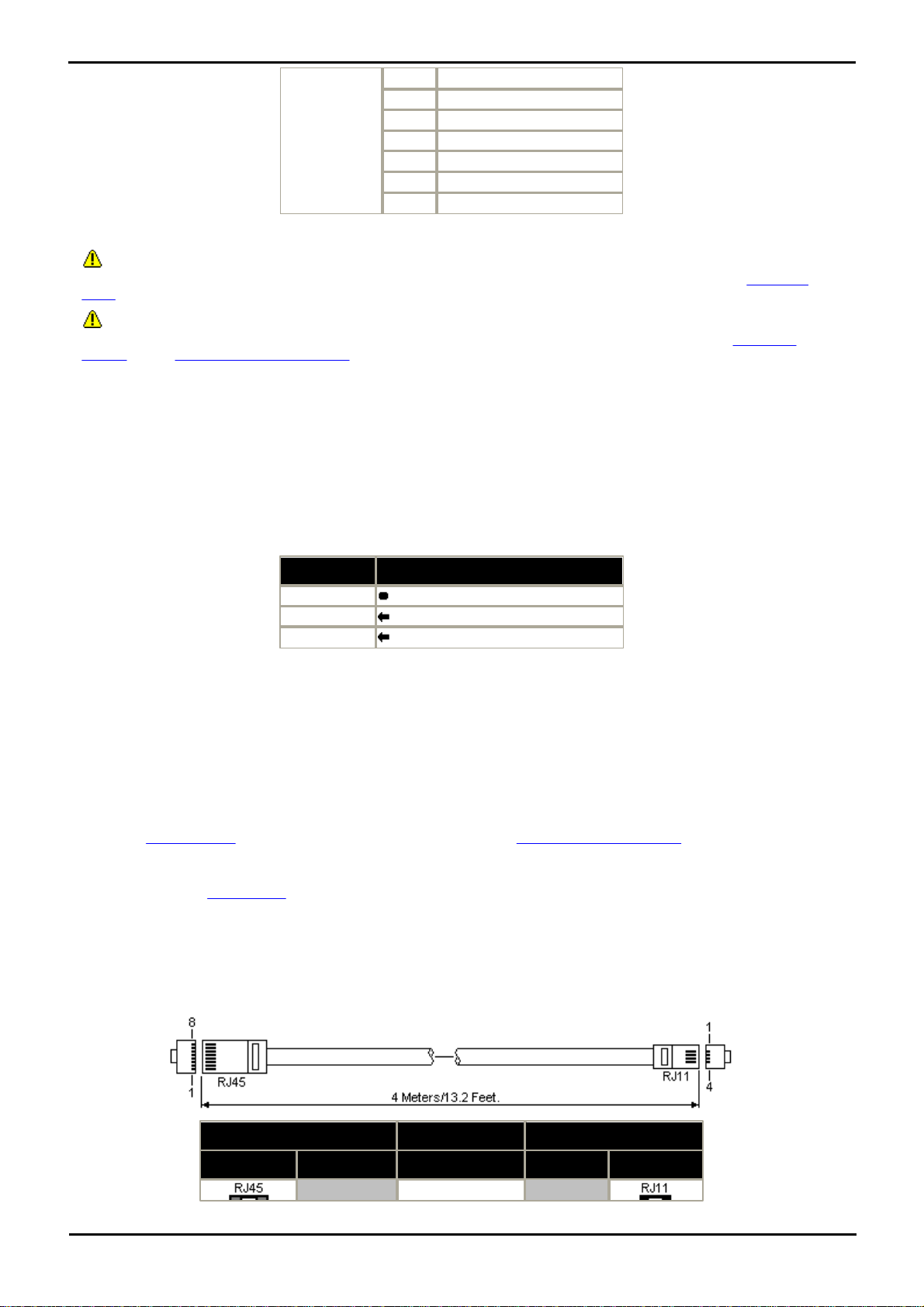
System Component Details: Physical Ports
2
Not used.
3
Not used.
4
Ring.
5
Tip.
6
Not used.
7
Not used.
8
Not used.
Pin No.
Description
Common
Common
Left
Audio In - Left Channel.
Right
Audio In - Right - Channel.
IP Office
Phone
DS Port
Pin
Description
Pin
Port
1
Not used.
–
· Off-Hook Current: 25mA.
· IMPORTANT
In all IP Office installations, any module being used for analog trunk connections must be connected to a functional
earth.
· WARNING
Within areas of high lightning risk, any module using analog trunk connections must be connected to a protective
ground and to surge protection equipment.
4.9.2 Audio Port
This port is found on the rear of the control unit. It is used for the input of an external music-on-hold sound source (not
yet implemented in PARTNER® Version). Note that if the IP Office has loaded an internal music-on-hold sound file, any
input from this socket is ignored.
The port is a 3.5mm stereo jack socket suitable for use with the most standard audio leads and connection to the
'headphone' output socket of most audio systems.
The use of a 'headphone' socket allows simple volume adjustment. Connection via a 'Line Out' socket may require
additional equipment in order to adjust the volume level.
· Input impedance: 10k /channel. Maximum a.c. signal – 200mV rms.
4.9.3 DS Ports
These ports are used for connection from an RJ45 structured cabling system to digital station phones supported by the
Essential Edition - PARTNER® Version.
Though the RJ11 to RJ11 cables supplied with most DS phones can be plugged directly into RJ45 ports including those on
Essential Edition - PARTNER® Version modules, this is not recommend as the connection lock is not positive and may
become disconnected.
DS ports on Digital Station V2 expansion modules can be connected to out-of-building extensions. If this is the case,
connection must be made via suitable protective devices at each end and via each building primary protection. In
addition the Digital Station module must be connected to a protective ground.
DS ports on IP 500v2 control units must not be connected to out-of-building extensions.
Structured Cabling Line Cord
This is an RJ45 to RJ11 cable suitable for connection from a structured cabling system RJ45 port to a DS phone. It can
also be used for two-wire analog phone extensions.
PARTNER® Version, Installation and Reference Manual Page 79
- Issue 1a (30 January 2010)IP Office Essential Edition
Page 81
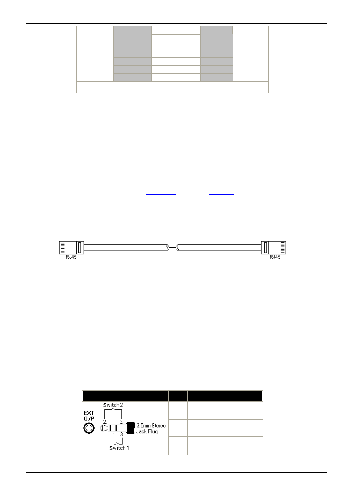
2
Not used.
1
3
Not used.
2
4
Signal 1.
3
5
Signal 2.
4
6
Not used.
5
7
Not used.
6
8
Not used.
–
Part number: 700047871
4.9.4 ETR Port
EXT O/P
Pin
Description
1
Switch 1.
2
Switch 2.
3
0 Volts (Ground/Chassis)
ETR (Enhanced Tip and Ring) ports are provided by the ETR6 base card. They can be used for the connection of DTMF
analog phone devices and Avaya ETR phones.
4.9.5 Expansion Port
This type of port is found on the rear of IP 500v2 control units and external expansion modules. It is used for connecting
the external expansion modules to the parent control unit.
The connection between these ports should only be done using an Avaya Expansion Interconnect Cable. No other cable
type should be used.
Expansion Interconnect Cable
The Expansion Interconnect cable is used to link expansion ports between the control unit and external expansion
module.
· Supply: One cable is normally supplied with each external expansion module.
· Part number: 1m (3'3") Blue cable - 700213457, 2m (6'6") Yellow cable - 700472871.
4.9.6 EXT O/P Port
The Essential Edition - PARTNER® Version control unit is equipped with a EXT O/P port. The port is marked as EXT O/P
and is located on the back of the control unit adjacent to the power supply input socket and uses a standard 3.5mm
stereo jack plug for connection.
The port can be used to control up to two external devices such as door entry relay switches. The usual application for
these switches is to activate relays on door entry systems. However, as long as the criteria for maximum current, voltage
and if necessary protection are met, the switches can be used for other applications.
The IP Office is able to open (high resistance), close (low resistance) or pulse (close for 5 seconds and then open) the
two switches within the port.
· CAUTION: In installations where this port is connected to a device external to the building, connection must be via a
towerMAX SCL/8 Surge Protector and a protective ground connection must be provided on the IP Office control unit.
The towerMAX range of devices are supplied by ITWLinx (http://www.itwlinx.com).
· Switching Capacity: 0.7A.
PARTNER® Version, Installation and Reference Manual Page 80
- Issue 1a (30 January 2010)IP Office Essential Edition
Page 82
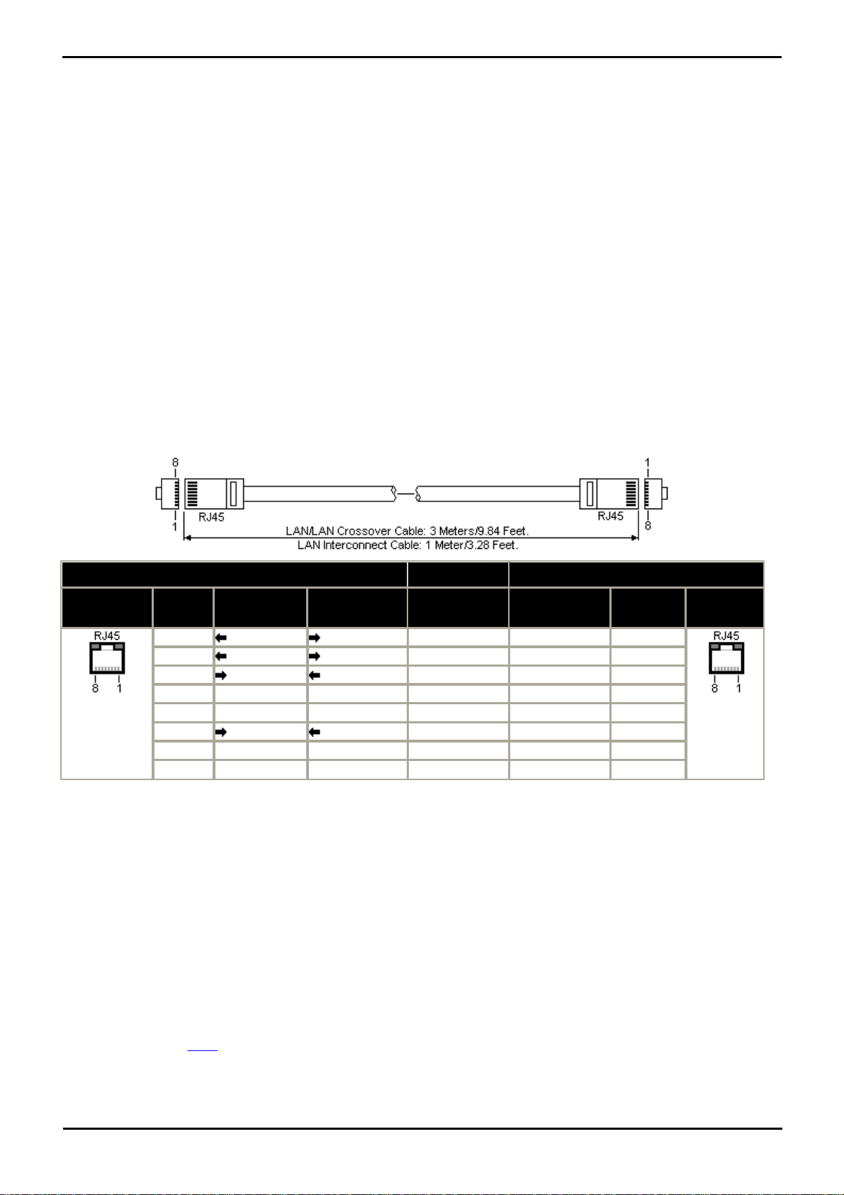
System Component Details: Physical Ports
IP Office
LAN
Pin
MDIX
(Normal)
MDI
(Crossover)
Wire
Standard/
Interconnect
Crossover
1
Rx-A.
Tx-A.
White/Orange
1
3
2
Rx-B.
Tx-B.
Orange/White
2
6
3
Tx-A.
Rx-A.
White/Green
3
1
4
Not used.
Not used.
Blue/White
4
4
5
Not used.
Not used.
White/Blue
5
5
6
Tx-B.
Rx-B.
Green/White
6
2
7
Not used.
Not used.
White/Brown
7
7
8
Not used.
Not used.
Brown/White
8
8
· Maximum Voltage: 55V d.c.
· On state resistance: 0.7 ohms.
· Short circuit current: 1A.
· Reverse circuit current capacity: 1.4A.
· Ensure that pins 1 and 2 are always at a positive voltage with respect to pin 3.
3.5mm stereo audio jack plugs are frequently sold as pre-wired sealed modules. It may be necessary to use a multi-
meter to determine the wiring connections from an available plug. Typically 3 (common to both relays) is the cable
screen.
4.9.7 LAN Port
The IP Office control unit has 2 RJ45 Ethernet ports, marked as LAN and WAN. These form a full-duplex managed layer-3
switch. Within the IP Office configuration, the physical LAN port is LAN1, the physical WAN port is designated LAN2 but
should not be used.
The LAN port LEDs indicate as follows:
· Green: On = connected, Flashing = Activity.
· Yellow: On = 100Mbps, Off = 10Mbps.
LAN Cables
These are CAT5 UTP cables for connection of various IP devices within the IP Office system.
· Part number:
4.9.8 PF Port
These ports are analog extension ports that can be used in conjunction with analog loop-start trunks during power failure
to the IP Office system. There are a number of options to connect analog extension ports to analog trunks during power
failure. In all cases these only work with loop-start analog trunks. Any phones connected to these ports should be clearly
labeled as power fail extensions in accordance with the appropriate national and local regulatory requirements.
When an IP Office 500Analog Phone 8 base card is fitted with an IP Office 500Analog Trunk daughter card, during power
failure extension port 8 is connected to analog trunk port 12. The same applies to the IP Office 500ATM Combination card
and the IP Office 500 ETR6 base card.
Any phones connected to these ports should be clearly labeled as power fail extensions in accordance with the
appropriate national and local regulatory requirements.
PARTNER® Version, Installation and Reference Manual Page 81
· LAN Cable - GREY: 700213481.
Standard straight LAN cable.
· LAN Crossover Cable - Black: 700213473.
LAN crossover cable.
- Issue 1a (30 January 2010)IP Office Essential Edition
Page 83
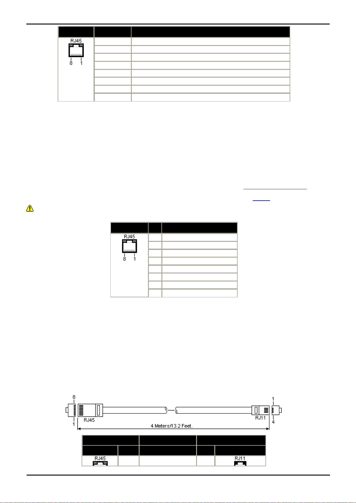
PF
Pin
Description
1
Not used.
2
Pin 2 is internally connected to pin 5 via a ringer capacitor.
3
Not used.
4
Ring.
5
Tip.
6
Pin 6 is internally connected to pin 5 via a ringer capacitor.
7
Not used.
8
Not used.
· Minimum Wire Size: AWG 26.
PHONE
Pin
Description
1
Not used.
2
Not used.
3
Not used.
4
Ring.
5
Tip.
6
Not used.
7
Not used.
8
Not used.
IP Office
Phone
DS Port
Pin
Description
Pin
Port
1
Not used.
–
· Maximum Cable Length:
· AWG26: 500m / 1640'.
· AWG24, AWG22: 1000m / 3280'.
4.9.9 Phone (POT) Port
These ports are analog extension ports. On expansion modules they can be connected to out-of-building extensions. If
this is the case, connection must be made via suitable protective devices (IP Office Barrier Box) at each end and via each
building primary protection. In addition the Phone module must be connected to a protective ground.
PHONE ports on Essential Edition - PARTNER® Version control units must not be connected to out-of-building
extensions.
· REN: 2
· Off-Hook Current: 25mA.
· Ring Voltage: 40V rms.
· Minimum Wire Size: AWG 26.
· Maximum Cable Length:
· AWG26: 0.5km / 1640 feet.
· AWG24, AWG22: 1km / 3280 feet.
Except on some older equipment, these ports do not include a ringing capacitor. Therefore for connection to 4-wire
analog phones where this is a requirement, connection should be via a Master socket containing ringing capacitors.
Message waiting is hard wired, 51 volt stepped
Structured Cabling Line Cord
This is an RJ45 to RJ11 cable suitable for connection from a structured cabling system RJ45 port to a DS phone. It can
also be used for two-wire analog phone extensions.
PARTNER® Version, Installation and Reference Manual Page 82
- Issue 1a (30 January 2010)IP Office Essential Edition
Page 84
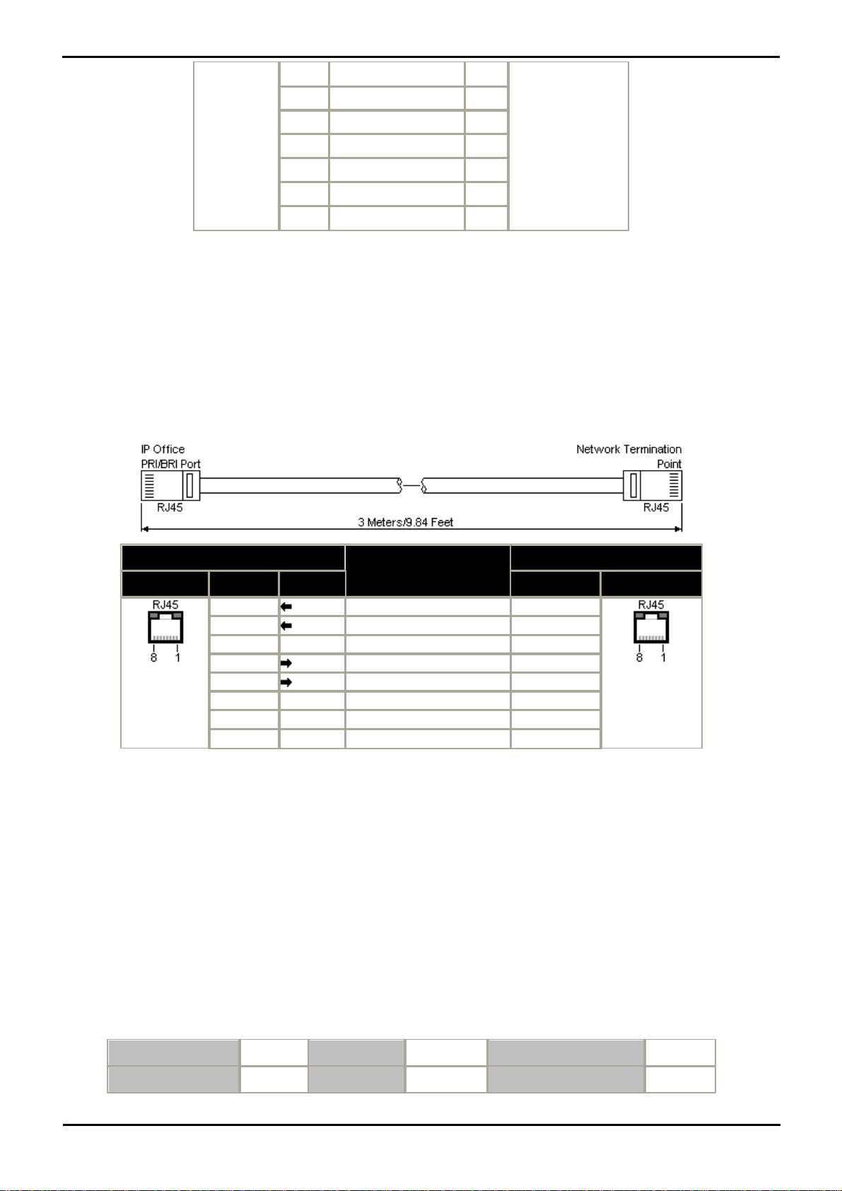
System Component Details: Physical Ports
2
Not used.
1
3
Not used.
2
4
Signal 1.
3
5
Signal 2.
4
6
Not used.
5
7
Not used.
6
8
Not used.
–
IP Office
Wire
Network Termination
RJ45
PRI
PIN
RJ45
1
Rx-A
White/Orange
1
2
Rx-B
Orange/White
2
3–White/Green
3
4
Tx-A
Blue/White
4
5
Tx-B
White/Blue
5
6–Green/White
6
7–White/Brown
7
8–Brown/White
8
Bits per second
38,400
Parity
None
Flow Control
None
Data bits
8
Stop Bits
1
Settings | Emulation
TTY
· Part Number: 700047871.
4.9.10 PRI Port
These ports are used for connection to PRI trunk services including E1, T1 and E1-R2.
PRI Trunk Cable
This cable is used to connect from trunk ports to the line providers network termination equipment. If that equipment
does not use RJ45 sockets, the cable may need to be stripped and rewired or an alternative cable used. The appropriate
signal pin-outs and wire colors are detailed below.
· Supply: PRI trunks cards are not supplied with these cables.
· Cable Color: Red.
· Part number: 700213440.
· Standard Length: 3m/9'10".
4.9.11 RS232 DTE Port
This port is found on the rear of the control unit and external expansion modules. The DTE ports on external expansion
modules are not used.
The RS232 DTE port on the control unit can be used for system maintenance and connection of serial terminal adaptors.
An asynchronous terminal program such as HyperTerminal is also required to manage the serial data exchange.
Configure this for operation via a PC serial port, as follows:
PARTNER® Version, Installation and Reference Manual Page 83
- Issue 1a (30 January 2010)IP Office Essential Edition
Page 85
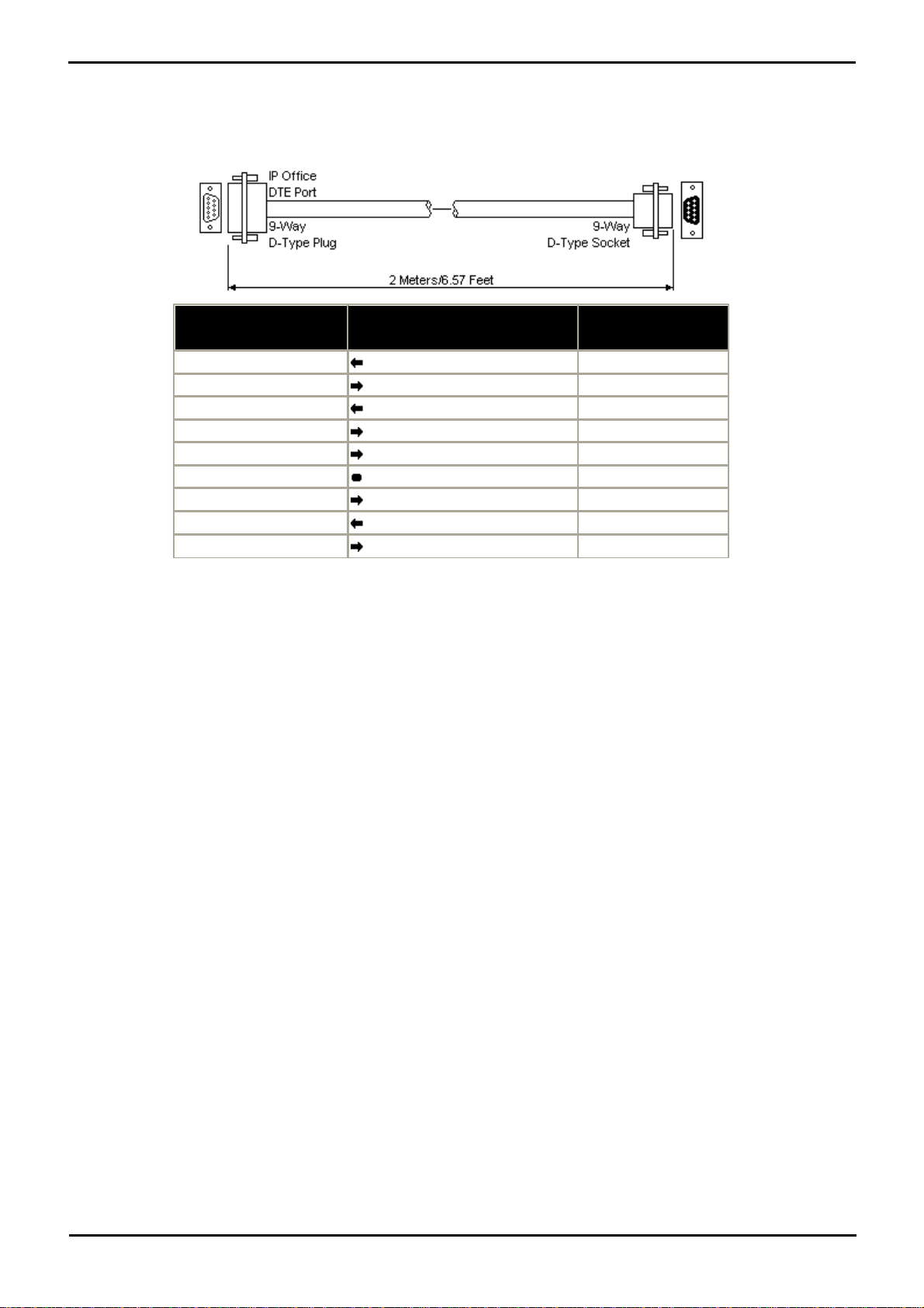
IP Office 9-Way RS232
DTE Port
Signal
PC/Terminal
Adaptor
3
Receive data
3
2
Transmit Data
2
7
RTS (Request To Send)
7
8
CTS (Clear To Send)
8
6
DSR (Data Set Ready)
6
5
Ground
5
1
DCD (Data Carrier Detect)
1
4
DTR (Data Terminal Ready)
4
9
RI (Ring Indicator)
9
DTE Cables
These cables are used for system maintenance and diagnostics under Avaya guidance. They can also be used for
connection of RS232 serial terminal adaptor equipment to the IP Office control unit. The cable required depends on the IP
Office control unit. This cable is a "Straight through DB9 female to DB9 male serial cable".
PARTNER® Version, Installation and Reference Manual Page 84
- Issue 1a (30 January 2010)IP Office Essential Edition
Page 86

System Component Details: Physical Ports
PARTNER® Version, Installation and Reference Manual Page 85
- Issue 1a (30 January 2010)IP Office Essential Edition
Page 87

Page 88

Chapter 5.
Administration
PARTNER® Version, Installation and Reference Manual Page 87
- Issue 1a (30 January 2010)IP Office Essential Edition
Page 89

5. Administration
This section lists the administration tasks that are involved in making any changes to the Essential Edition - PARTNER®
Version set-up. These actions are achieved by using IP Office Manager Essential Edition - PARTNER® Version application.
Please refer to the IP Office Manager Essential Edition - PARTNER® Version Admin Tool User Guide for detail.
· Changes to system parameters
· Changes to users, groups and lists
· Trunk set-up
· Auxiliary equipment connection
· Auto attendant set-up
· STUN settings for networks
· Management of the SD card
5.1 Initial Configuration
.
This section covers basic configuration changes required for all Essential Edition - PARTNER® Version systems.
· Change the Default Passwords
· Change the System Name and IP Address /DHCP Settings
· Trunk Configuration
· Remove Unused Trunks
Disabling the use of trunks and trunk channels that are not available.
· Select the Clock Source for Digital Lines
Altering which digital trunk is used to provide the IP Office with its clock signal for call synchronization.
· Enter Trunk Prefixes
On systems where a prefix is being used for external dialing, ensure that the same prefix is added to incoming
numbers in order to allow return calls.
5.2 Changing the Default Password
WARNING - Password Change Required
New Essential Edition - PARTNER® Version systems use default security settings. These settings must be changed to
make the system secure. As a minimum, you should change the default Remote/Administrator Password if IP Office
Manager Essential Edition - PARTNER® Version is to be attached. Failure to do so will render the Essential Edition PARTNER® Version system potentially unsecured.
Remote administration password
This password controls remote or local access to the Essential Edition - PARTNER® Version system to make
administrative changes to the overall set-up such as changes to the configuration or equipment. The administration
password can only be changed by an administrator.
1.From the Manager home page select Change Remote / Administration Password. A log in dialog is displayed
2.Provide login detail and enter password (case sensitive) as your default password. The change dialog is displayed.
3.Make required changes and click OK.
Remember you are changing the password for accessing the Essential Edition - PARTNER® Version system to which
you are attached, not the manager application.
System Password
Once Essential Edition - PARTNER® Version is installed the responsibility for setting this password rests with the
customer. You should point this fact out and if required, make the change before you leave as follows:
Change system password using Manager
1.Click the hot link "Change System Settings"
PARTNER® Version, Installation and Reference Manual Page 88
- Issue 1a (30 January 2010)IP Office Essential Edition
Page 90

Administration: Changing the Default Password
2.In the System Parameters box, change system password (Field accepts digits only)
Customer's administrator using a telephone handset
1.Dial #403
2.Dial four chosen digits to set the system password
5.3 SD Card Actions
The SD Card exercises the central control of Essential Edition - PARTNER® Version. There are a number of actions that
can be taken as part of IP Office administration as follows:
· Shutdown and start-up an SD card
· Format an SD card
· Read, write and delete files on an SD card
· Copy/Recreate an SD card
· Backup an SD card
5.3.1 Removing SD Cards
SD Card Removal
SD cards should never be removed while being used. Though the SD card slot LEDs indicate when data is being
written to an SD card, lack of flashing LED is not a sufficient safeguard. The IP Office Manager provides methods to
shutdown and restart an individual card or to shutdown the Essential Edition - PARTNER® Version system in order to
allow removal of an SD card. If the System SD card is removed, licensed features will continue operating for up to 2
hours.
5.3.1.1 Card Shutdown
Before a memory card is removed from an Essential Edition - PARTNER® Version system that is running, the card should
be shutdown. Removing a memory card while the system is running may cause file corruption.
Shutting down the memory card disables all services provided by the card including embedded voicemail. Features
licensed by the memory card will continue to operate for up to 2 hours.
Card services can be restarted by either reinserting the card or using a Start Up command.
Card Shutdown Using Manager
1.Using IP Office Manager, select File | Advanced | Memory Card Commands | Shutdown.
2.In the Select IP Office dialog, select the IP Office system containing the memory card.
3.Click OK.
4.At the back of the control unit, confirm that the memory card LED is off.
5.The card can now be removed in order to perform the necessary maintenance actions.
SD Card Removal
SD cards should never be removed while being used. Though the SD card slot LEDs indicate when data is being
written to an SD card, lack of flashing LED is not a sufficient safeguard. The IP Office Manager provides methods to
shutdown and restart an individual card or to shutdown the Essential Edition - PARTNER® Version system in order to
allow removal of an SD card. If the System SD card is removed, licensed features will continue operating for up to 2
hours.
PARTNER® Version, Installation and Reference Manual Page 89
- Issue 1a (30 January 2010)IP Office Essential Edition
Page 91
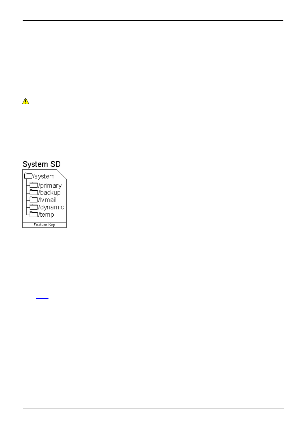
5.3.1.2 Card Startup
· primary
Contains the firmware files for the IP Office control unit, external expansion modules and
supported phones. The folder can also contain music on hold files and license key files. This is the
main set of files used by the IP Office system when booting up. Also contains the stored copy of
the IP Office configuration.
· backup
Contains a copy of the primary folder at some previous point. A backup copy of the primary
contents to this folder can be invoked manually (using Manager or SSA) or as part of the IP Office
software upgrade using Manager.
· lvmail
Contains the prompts used by embedded voicemail and the mailbox messages.
· dynamic
Contains files used by the IP Office and retained through a reboot of the IP Office system.
· temp
Contains temporary files used by the IP Office and not retained through a reboot of the IP Office
system.
Fixed system files comprise:
Dynamic system files comprise:
· IP Office 500 firmware binary
· Expansion binaries
· All current DCP phone binaries
· All current IP phone binaries
· ADMM base station binary
· Embedded voicemail prompts
· Embedded AA clips
· System configuration
· DHCP allocation
· Call logs
· Music On Hold (Not yet implemented)
· Embedded voicemail recordings
· Sysmon logs
· SMDR buffer logs
Reinserting a card into a system that is already switched on will automatically restart the card. Similarly reinserting the
card and rebooting the IP Office system will restart the card. However, if the card has been shutdown but not removed, it
can be restarted using Manager without requiring a reboot.
Card Startup Using Manager
1.Using IP Office Manager, select File | Advanced | Memory Card Commands | Startup.
2.Using the Select IP Office menu, select the IP Office system containing the memory card.
3.Click OK.
After reinsertion, the SD card may not be fully functional until two hours have elapsed.
5.3.2 Directories and Files
The System SD card contains the following folders:
The Optional SD card can contain a similar set of folders. These are used as an additional backup or they can be used as
the source for upgrading the contents of the System SD card.
Files present on an SD system card can be classified into three differing types:
1.Fixed System files – files essential for system operation that are fixed in name and/or location
2.Dynamic System files – files essential for system operation that are dynamic in nature (e.g. voice messages, Sysmon
and SMDR buffer logs)
3.Non system files – all others
PARTNER® Version, Installation and Reference Manual Page 90
- Issue 1a (30 January 2010)IP Office Essential Edition
Page 92
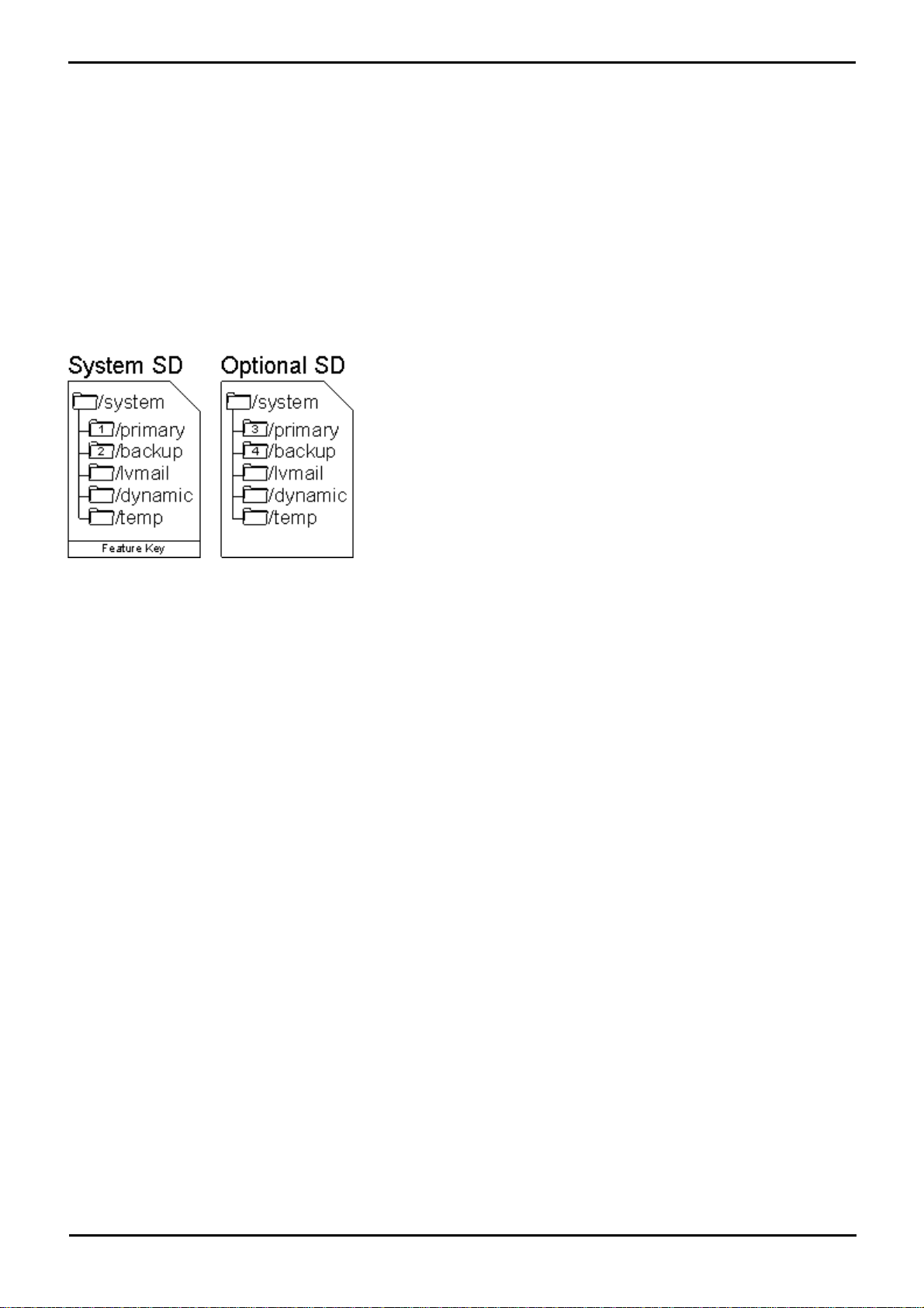
Administration: SD Card Actions
· License merge
Fixed System Files only exist in two
directories: ‘\system\primary’ and
‘\system\backup’. Some fixed system files
must be specifically named. They have the
system and read-only file attributes set to
reduce inadvertent deletion/modification
Dynamic system files only exist in one
directory: ‘\system\dynamic’ and are
usually dynamically named. They have
the system file attribute set to reduce
inadvertent deletion.
During power up, Essential Edition - PARTNER® Version looks for valid
firmware to load into memory in the following order.
1.System SD card primary folder.
2.System SD card backup folder.
3.Optional SD card primary folder.
4.Optional SD card backup folder.
5.BootP request to IP Office Manager.
Non system files can be any type, including copies of any of the above – it is the directory and name that determine the
type of file.
5.3.3 Booting from the SD Cards
The control unit can be forced to bypass the primary folder by pressing the Aux switch on the rear panel when applying
power to the control unit.
5.3.4 SD Card Removal
Before a memory card is removed from an Essential Edition - PARTNER® Version system that is running, the card should
be shutdown. Removing a memory card while the system is running may cause file corruption.
Shutting down the memory card disables all services provided by the card including embedded voicemail. Features
licensed by the memory card will continue to operate for up to 2 hours.
Card services can be restarted by either reinserting the card or using a Start Up command.
Card Shutdown Using Manager
1.Using IP Office Manager, select File | Advanced | Memory Card Commands | Shutdown.
2.In the Select IP Office dialog, select the IP Office system containing the memory card.
3.Click OK.
4.At the back of the control unit, confirm that the memory card LED is off.
5.The card can now be removed in order to perform the necessary maintenance actions.
Card Reinsertion
Reinserting a card into a system that is already switched on will automatically restart the card. Similarly reinserting the
card and rebooting the IP Office system will restart the card. However, if the card has been shutdown but not removed, it
can be restarted using Manager without requiring a reboot.
Card Startup Using Manager
1.Using IP Office Manager, select File | Advanced | Memory Card Commands | Startup.
PARTNER® Version, Installation and Reference Manual Page 91
- Issue 1a (30 January 2010)IP Office Essential Edition
Page 93
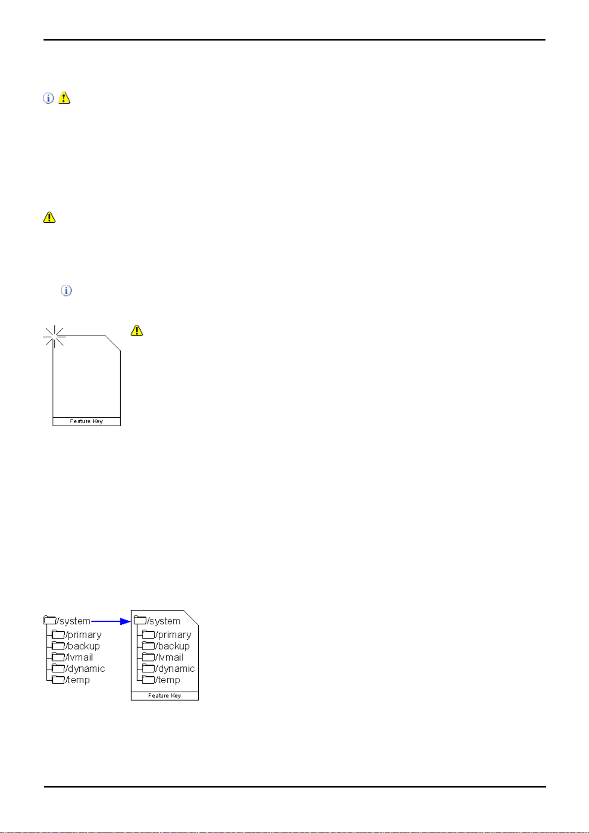
2.Using the Select IP Office menu, select the IP Office system containing the memory card.
· WARNING: All File Will Be Erased
Note that this action will erase any existing files and folders on the card. Once a card has been
formatted, the folders and files required for Essential Edition - PARTNER® Version operation can be
loaded onto the card from the Manager PC using the Recreate IP Office SD Card command.
1.Insert the SD card into a reader slot on the Manager computer.
2.From Manager main menu, select File | Advanced | Format IP Office SD Card.
3.Select IP Office Partner Version. This selection just sets the card label shown when viewing
the card details. It does not affect the actual formatting. Select the label that matches the files
set you will be placing on the card.
4.Browse to the card location and click OK.
5.The status bar at the bottom of Manager displays the progress of the formatting process.
6.When the formatting is complete, you can use the Recreate IP Office SD Card command to
load the IP Office folders and files onto the card from the Manager PC.
1.Note: This process can take up to 20 minutes depending on the PC. Once
started it is recommended that the process is not interrupted.
2.Insert the SD card into a reader slot on the Manager computer.
3.Using Manager, select File | Advanced | Recreate IP Office SD Card.
4.Select IP Office Partner Version. This selection will affect how the Essential
Edition - PARTNER® Version system operates when defaulted with this card
present in its System SD card slot. .
5.Browse to the card location and click OK.
6.Manager starts creating folders on the SD card and copying the required files
into those folders.
3.Click OK.
If the SD card is removed, license information is retained for approximately two hours, thus allowing Essential
Edition - PARTNER® Version to continue operation.
When a card is subsequently reinserted the control unit may not function correctly for the first two hours.
5.3.5 Recreating an IP Office SD Card
The new card must be correctly formatted because, for the System SD slot only Avaya SD cards with a Feature Key
should be used.
WARNING
Avaya supplied SD cards should not be formatted using any other method than the format commands withinEssential
Edition - PARTNER® Version Manager and IP Office System Status Application. Formatting the cards using any other
method will remove the feature key used for IP Office licensing from the card.
Note: This task requires a PC with an SD card read/write drive attached and IP Office Manager Essential Edition PARTNER® Version software installed
Only this method should be used for formatting an Avaya SD card. Using IP Office Essential Edition - PARTNER®
Version Manager ensures that special files required for Essential Edition - PARTNER® Version operation are created
and that the Feature Key information is retained.
Format rules: SDHC minimum 4GB FAT32 format (Single partition, SDHC, class2+, FAT32, SPI & SD bus).
Writing an IP Office SD Card
This process will create the folder structure on the SD card and copy the necessary firmware files from those installed
with Manager onto the SD card. This includes the binary files for the IP Office 500v2 system, any external expansion
modules and phones. It also includes the prompt files for embedded voicemail operation.
This process can be used to upgrade an existing SD card to match the file set installed with Manager. For the card to be
used in an IP Office 500v2 system System SD slot the card must be Avaya SD Feature Key card. The card must be
correctly formatted (see Format IP Office SD card).
PARTNER® Version, Installation and Reference Manual Page 92
- Issue 1a (30 January 2010)IP Office Essential Edition
Page 94
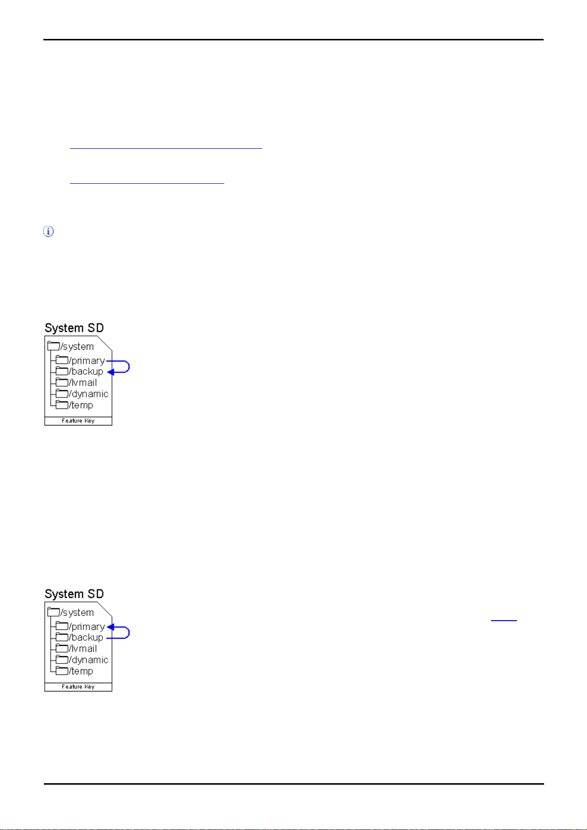
Administration: SD Card Actions
This process copies the contents of the backup folder on the System SD card over the primary
folder. Any files with matching file names will be replaced.
This process copies the contents of the backup folder on the System SD card over the primary
folder. Any files with matching file names will be replaced.
To make the restored files active the IP Office system then needs to be restarted using a reboot.
5.3.6 Backing Up the System SD Card
There are two levels of backup that can be performed.
· Backup the System SD Card Primary Folder
The contents of the primary folder on the card can be copied to the backup folder. They files can then be restored
if necessary. Both actions can be performed remotely.
· Backup the Whole System SD Card
The contents of the whole System SD card can be copied to the Optional SD card. While this can be done
remotely, the contents can only be copied back manually using an SD card reader.
Note that in either case, the configuration file on the System SD card will not contain any changes made by IP Office
users since the last overnight backup or the last system shutdown.
5.3.6.1 Backup the System Primary Folder
Backing up the primary folder to the backup folder using Manager
1.Using Manager main menu, select File | Advanced | Embedded File Management.
2.From the Select IP Office dialog, tick the box beside the IP Office system you want to work with.
3.The file contents of the memory cards are displayed.
4.Select File | Backup System Files.
5.The contents of the primary folder on the System SD card will be copied to the backup folder.
5.3.6.2 Restore from the System Backup Folder
Restoring the system backup folder to the primary using Manager
1.Using Manager main menu, select File | Advanced | Embedded File Management.
2.From the Select IP Office dialog, tick the box beside the IP Office system you want to work with.
3.The file contents of the memory cards are displayed.
PARTNER® Version, Installation and Reference Manual Page 93
- Issue 1a (30 January 2010)IP Office Essential Edition
Page 95

4.Select File | Backup System Files.
This process copies all files on the System SD card to the Optional SD card. It
includes the primary and backup folders and the embedded voicemail files
including message files.
Any matching files and folders on the Optional SD card are overwritten.
There is no in-built method for copying the contents of an Optional SD card
back onto a System SD card. If that is necessary it must be done by
removing the cards and copying files using a PC SDHC compatible card
reader.
5.The contents of the primary folder on the System SD card will be copied to the backup folder.
5.3.6.3 Copying the System Card to the Optional Card
Copying the system card to the optional card using Manager
1.Using Manager main menu, select File | Advanced | Embedded File Management.
2.From the Select IP Office dialog, tick the box beside the IP Office system you want to work with.
3.The file contents of the memory cards are displayed.
4.Select File | Copy System Card.
5.The contents of the System SD card are copied to the Optional SD card.
5.4 External Trunk Configuration
This section cover the basic requirements for external trunk configuration. The exact method of physical connection and
configuration will vary with each trunk provider and so requires local telecoms experience. The topics covered here are
general guidelines.
· Clock Quality
Altering which digital trunk is used to provide the IP Office with its clock signal for call synchronization.
· Unused Trunks
Disabling the use of trunks and trunk channels that are not available.
· Prefix Dialing
On systems where a prefix is being used for external dialing, ensuring that the same prefix is added to incoming
numbers in order to allow return calls.
Details may be found in the IP Office Manager Essential Edition - PARTNER® Version Administrator Tool User Guide
5.4.1 Clock Quality
Any system where digital trunks are being used requires a clock signal for call synchronization between the switches at
each end of the trunk. Typically the clock signal provided by a digital trunk from the central office exchange is the best
quality and most reliable source.
The Essential Edition - PARTNER® Version can obtain and use the clock signal from any of its digital trunks. However it
will only use one trunk for its clock signal at any time and will ignore any other possible clock sources. If no clock source
is available the Essential Edition - PARTNER® Version can use its own internal clock if necessary.
The Clock Quality setting on each line is set to one of the following:
· Network
If available, the clock signal from this trunk can be used as the Essential Edition - PARTNER® Version clock
source.
PARTNER® Version, Installation and Reference Manual Page 94
- Issue 1a (30 January 2010)IP Office Essential Edition
Page 96
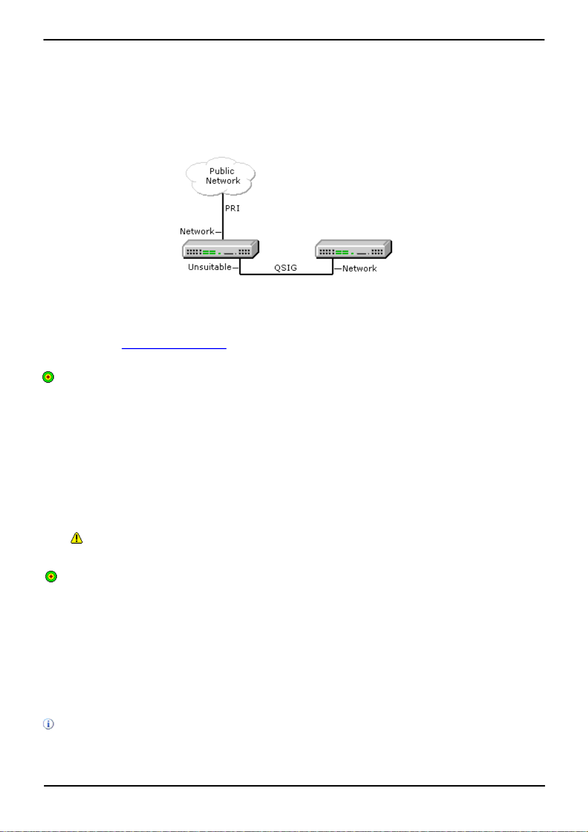
Administration: External Trunk Configuration
· Fallback
If available, the clock signal from this trunk can be used as the clock source only if none of the trunks set to
Network are providing a clock source.
· Unsuitable
The clock source from this trunk is never used as the IP Office clock source.
In the example below the first Essential Edition - PARTNER® Version is set to use the public network trunk as its clock
source and ignoring the possible clock source from the QSIG trunk. However the other system is using the QSIG trunk as
it clock source.
Source Priority
When multiple trunks with the same setting are providing a clock signal, the trunk used is determined in the following
order of slots 1 to 4 and then by port on each slot.
Viewing the Current Clock Source
The current clock source being used by an Essential Edition - PARTNER® Version system is shown on the Resources page
within the IP Office System Status Application.
Objective - Set a chosen digital trunk as the network clock source and set all other digital trunks as fallback or
unsuitable.
Refer to the IP Office Manager Essential Edition - PARTNER® Version Administrator documentation.
5.4.2 Unused Trunks
Each IP Office trunk card provides a fixed number of trunk ports. For digital trunks each trunk provides a set number of
digital channels. In cases where the number of trunks connected to the Essential Edition - PARTNER® Version is lower or
the number of channels provided is lower, those unused trunks and channel must be disabled.
· Failure to do this will cause problems with outgoing calls. For example, on a system with an ATM4 trunk card
fitted but only two analog trunks actually connected, failure to disable the other two trunks within the Essential
Edition - PARTNER® Version configuration will cause 50% of outgoing call attempts to fail.
Objective
Remove unused trunks and channels from the telephone system configuration.
Refer to the IP Office Manager Essential Edition - PARTNER® Version Admin Tool (Manager) User Guide.
5.5 Changing Components
Base cards and external expansions modules must only be removed and added to an Essential Edition - PARTNER®
Version system when that system is switched off.
In the sections below, the term component can refer to a card fitted into the control unit or an external expansion
module.
Note that for extension ports, by default both an extension entry and a user entry will exist in the Essential Edition PARTNER® Version configuration. Extension entries can be deleted without deleting the corresponding user entry. This
allows retention of the user settings and association of the user with a different extension by changing the extensions
Base Extension number to match the user's Extension ID.
PARTNER® Version, Installation and Reference Manual Page 95
- Issue 1a (30 January 2010)IP Office Essential Edition
Page 97

Like for Like Replacement
If replacing with a component of the same type no configuration changes are necessary.
1.Switch off the Essential Edition - PARTNER® Version system.
2.Remove the card or external expansion module. Note the card slot or expansion port used as the replacement
must be installed in the same position.
3.Install the replacement using the appropriate process for the type of component (Fitting IP Office 500 cards).
4.Restart the IP Office system.
Higher Capacity Replacement
If replacing with a component of the same type but higher capacity, when restarted the IP Office will automatically create
configuration entries for the new trunks or extensions/users.
1.Switch off the Essential Edition - PARTNER® Version system..
2.Remove the card or external expansion module. Note the card slot or expansion port used as the replacement
must be installed in the same position.
3.Install the replacement using the appropriate process for the type of component (Fitting IP Office 500 cards).
4.Restart the IP Office system.
5.Use Manager to configure the new trunks or extensions/users.
Lower Capacity Replacement
If replacing with a component of the same type but lower capacity, after restarting the IP Office the configuration will
need to be edited to remove redundant entries.
1.Switch off the Essential Edition - PARTNER® Version system..
2.Remove the card or external expansion module. Note the card slot or expansion port used as the replacement
must be installed in the same position.
3.Install the replacement using the appropriate process for the type of component (Fitting IP Office 500 cards).
4.Restart the IP Office system.
5.Use Manager to delete the trunks or extensions/users in the configuration that are no longer supported by the
component installed.
Adding a New Component
If adding a new component to an available slot or port, when restarted the IP Office will automatically create
configuration entries for the new trunks or extensions/users.
1.Switch off the Essential Edition - PARTNER® Version system..
2.Install the replacement using the appropriate process for the type of component (Fitting IP Office 500 cards).
3.Restart the IP Office system.
4.Use Manager to configure the new trunks or extensions/users.
Permanent Removal
If permanently removing the component, the configuration will need to be edited to remove redundant trunk or
extension/user entries.
1.Switch off the Essential Edition - PARTNER® Version system.
2.Remove the card or external expansion module.
3.Restart the IP Office system.
4.Use Manager to delete the trunks or extensions/users in the configuration that relate to the component removed.
5.In the Control Unit section of the configuration, delete the entry for the component that is no longer present in
the system.
Replacement of a Different Type
If replacing a component with one of a different type, the process should be divided into two stages. First remove the
existing component using the Permanent Removal process above and adjust the configuration and reboot. Then install
the new component using the Adding a New Component process above.
PARTNER® Version, Installation and Reference Manual Page 96
- Issue 1a (30 January 2010)IP Office Essential Edition
Page 98
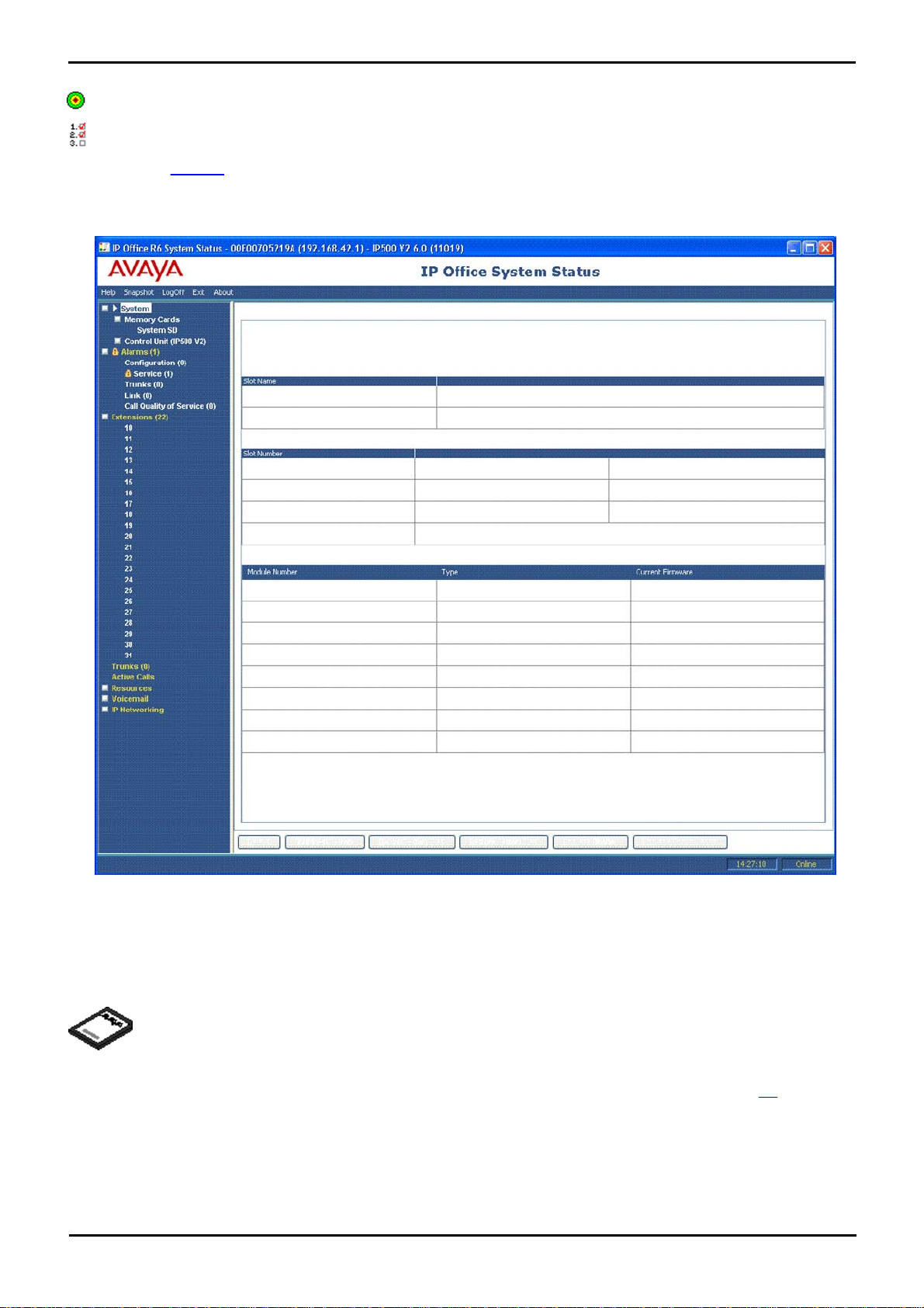
Administration: Changing Components
License keys strings are used to activate various IP Office features of the Essential Edition - PARTNER®
Version system.
5.5.1 Running SSA
Objective - Allow SSA to be used to check the correct installation of additional equipment.
Procedure
1.From the Manager home page select File | Advanced | System Status.
2.Click Logon.
3.SSA shows Waiting for connection and then the Essential Edition - PARTNER® Version system status.
5.6 Adding Licences
Each license is a unique 32-character string based on the feature being licensed and the serial number of the SD card
plugged into the system control unit. It is recommended that you use the Import control to import licenses. Alternatively
the license keys can be cut and pasted into the Key field. Entering licenses manually is liable to errors caused by mis
keying of the correct 32-character string.
PARTNER® Version, Installation and Reference Manual Page 97
- Issue 1a (30 January 2010)IP Office Essential Edition
Page 99
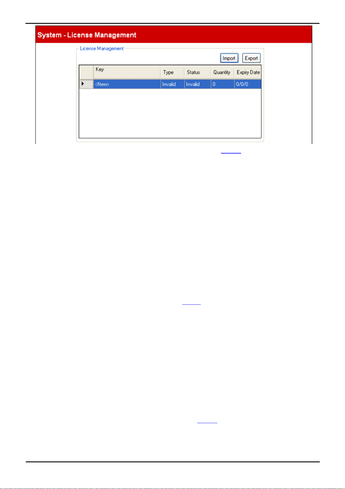
This dialog is reached by selecting System | License Management from the Manager Admin Tasks pane. It is used
to enter licenses required for additional telephone system features. For example licenses are used to enable
additional voicemail ports or the twinning feature.
· Import
Import licenses from a CSV file. Each line of the file should contain a license name and the 32-character license
key, each separated by a comma.
· Export
Export the licenses to a CSV file. (Only if exportable licenses are present on the system)
For each license key entered, the following information is displayed:
· Key
This is the 32-character license string.
· Type: Information field, not editable.
If the Key is recognized, the name of the feature it licenses is shown in this field. If Invalid is displayed it
indicates that the Key has not been correctly entered.
· Status:
This field shows the status of the license.
· Unknown is shown for newly entered licenses until the configuration is sent to the phone system and then
reloaded again.
· Valid is shown if the license key matches the SD card serial number.
· Invalid is shown if the license key does not match the SD card serial number.
· Dormant is shown if the license key is valid but is conditional on another license that is not present.
· Obsolete is shown if the license key is valid but the license is no longer used by the version of software
installed in the phone system.
· Quantity: Information field, not editable.
This field indicates how many items are enabled by the license. The meaning of this will vary depending on the
feature being licensed.
· Expiry Date: Information field, not editable.
Some licenses have an expiry date. This field will indicate that date.
5.7 Additional Processes
5.7.1 Upgrading the System
Upgrade is performed using the Upgrade Wizard tool within the IP Office Manager Essential Edition - PARTNER® Version
application (File | Advanced | Upgrade). It displays the systems it can detect, their existing software level and the levels
it has available.
PARTNER® Version, Installation and Reference Manual Page 98
- Issue 1a (30 January 2010)IP Office Essential Edition
Page 100
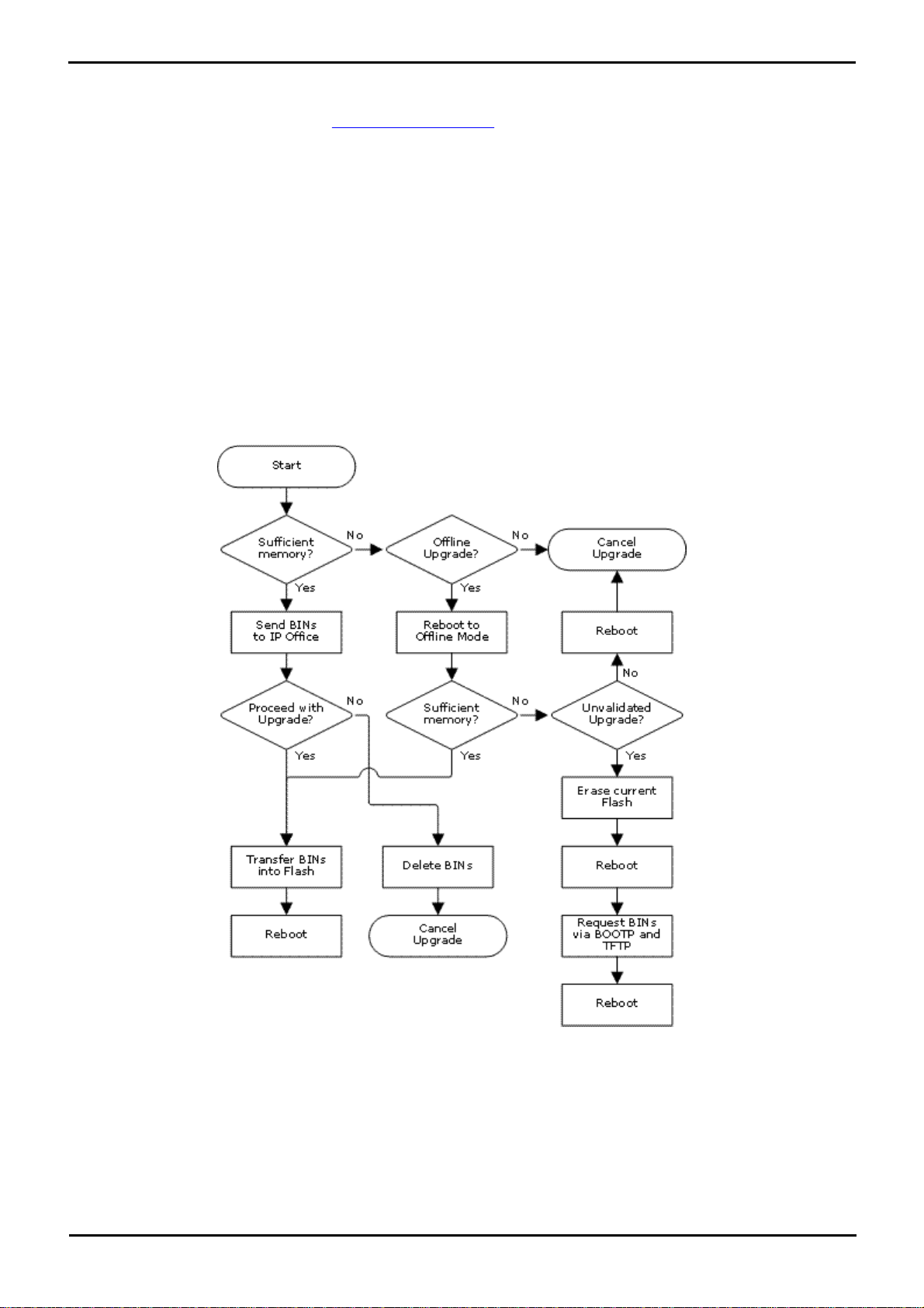
Administration: Additional Processes
· Check IP Office Technical Bulletins
Whenever upgrading check the latest IP Office Technical Bulletins for the various IP Office software releases involved
before proceeding. These may contain information relating to changes that occurred after this document was
completed. Bulletins are available from http://support.avaya.com.
· Multi-Stage Upgrades
The upgrade path may require several intermediate upgrades. Skipping an intermediate level may lead to incorrect
system operation and configuration corruption. Multi-stage upgrades are only necessary for control units. External
expansion modules can be upgraded directly between any two levels supported by the module.
There are two methods that the IP Office may use for upgrading, these are Validated, and Non validated.
· Validated Upgrade
This is the preferred method and can be used with any IP Office system that already has IP Office software. By default
the Validate option within the Upgrade Wizard is pre-selected. During this process, the required BIN files are first
transferred to the IP Office RAM memory. Only when the files are received will the IP Office overwrite the existing
software in its Flash memory and restart using the new files.
· Non validated Upgrade
This is the least preferred upgrade method. It should only be used from a PC directly connected to the IP Office and
with a fixed IP address on the same LAN domain as the IP Office LAN1. This method involves erasing the existing
software in the IP Office Flash memory and then copying the new BIN files directly to the Flash memory. Its uses
BOOTP and TFTP and requires a BOOTP entry for the IP Office system to exist on the Manager PC. This method should
not be used unless absolutely necessary.
Upgrade Process
PARTNER® Version, Installation and Reference Manual Page 99
- Issue 1a (30 January 2010)IP Office Essential Edition
 Loading...