

Page 1

Avaya Solution & Interoperability Test Lab
Connecting Avaya 4600 Series IP Telephones and Avaya
Wireless LAN Access Points with the 3Com SuperStack 3
Switch 4400-PWR (Inline Power Ethernet Switch) - Issue 1.0
Abstract
These Application Notes describe how to connect and configure Avaya 4600 Series IP
Telephones and Avaya wireless LAN access points with the 3Com SuperStack 3 Switch 4400PWR (inline power Ethernet switch). The various Avaya powering arrangements and the
commands for displaying and controlling the powering status of the switch ports are described.
SZ; Reviewed:
WCH 3/19/2004
Solution & Interoperability Test Lab Application Notes
©2004 Avaya Inc. All Rights Reserved.
1 of 14
3com-PoE-Config.doc
Page 2

1. Introduction
“Inline power” is a feature offered on some Ethernet switches. It is a means by which the switch
can supply power to a network device within the same cable that carries the Ethernet signaling.
This simplifies network installation and powering design, removing the need for a separate
power supply for each IP telephone in the network. IEEE 802.3af-2003 defines a standard
protocol to be used by powering and powered devices.
The 3Com SuperStack 3 Switch 4400-PWR is a 24-port (24 10/100Base-TX) Ethernet switch. It
supplies 150 watts of power for PoE applications compatible with the IEEE 802.3af-2003
standard. Avaya 4600 Series IP telephones, Avaya wireless LAN access points, and the 3Com
SuperStack 3 Switch 4400-PWR comply with this standard. These Application Notes show how
Avaya IP telephones and wireless LAN access points can be connected to the 3Com SuperStack
3 Switch 4400-PWR. Web-based configuration that display and control powering status of the
switch ports are also demonstrated.
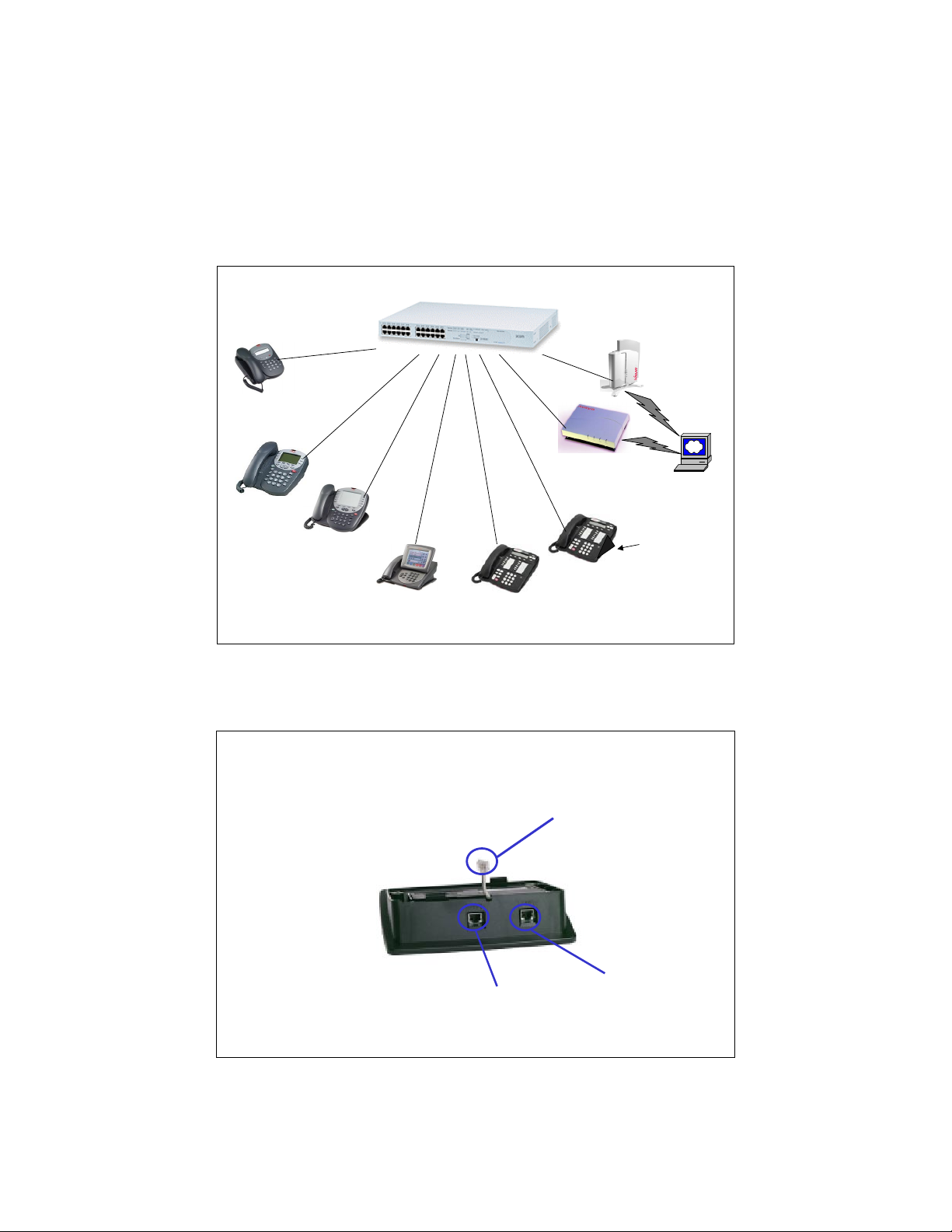
The Avaya product configurations addressed by these Application Notes are shown in Figure 1.
The following Avaya products are directly connected to the switch:
• 4602 and 4602SW IP Telephones
• 4610SW IP Telephone
• 4620 and 4620SW IP Telephones (including the optional EU24 Button Expansion
Module)
• 4630SW IP Screenphone
• Gen-2 4606, 4612, and 4624 IP Telephones
• Gen-1 4612 and 4624 IP Telephones with 30A Ethernet Switch Base
• AP 3 and AP 5 Access Points
The Gen-1 Avaya 4612 and 4624 IP Telephones require the Avaya 30A Switch Base if power
over Ethernet is required. Figure 2 shows the connections for the 30A switch base. The 4612
and 4624 telephones can be identified as Gen-1 or Gen-2 by inspecting the model number. “1A”
in the model number indicates Gen-1; “2A” indicates Gen-2. The model number can be found
by:
• Inspecting the label attached to the bottom of the telephone.
OR
• Pressing Mute, V, I, E, W, # on the keypad and then pressing * until the model number
appears. Press # to exit.
Examples of model numbers are “4612D01A-003” (Gen-1) and 4612D02A-003 (Gen-2).
The powering tests included verification of the following after each product was connected to the
switch:
SZ; Reviewed:
WCH 3/19/2004
Solution & Interoperability Test Lab Application Notes
©2004 Avaya Inc. All Rights Reserved.
2 of 14
3com-PoE-Config.doc
Page 3
• Successful boot operation
• For IP telephones, successful registration with an Avaya Media Server/Gateway and
successful completion of calls using the IP telephones (e.g. initiate calls, receive calls,
etc.)
• For wireless LAN access points, successful registration of a wireless laptop and use of
the administration web interface on the access point from the laptop.
3Com SuperStack 3 Switch
3Com SuperStack 3 Switch
4400--
PWR
4400
PWR
Avaya AP 5
Access Point
Avaya 4602,
4602SW IP
Telephones
Avaya 4610SW
IP Telephone
Telephones with
Avaya 4620,
4620SW IP
EU24
Avaya 4630SW
IP Screenphone
Avaya Gen-2
4606, 4612, 4624 IP
Telephones
Avaya AP 3
Access Point
Avaya Gen-1
4612 & 4624 IP
Telephones
Wireless
Wireless
Laptop
Laptop
Avaya 30A
Ethernet Switch
Base
Figure 1: Avaya 4600 Series IP Telephone and Wireless LAN Access Point Configurations
with the 3Com SuperStack 3 Switch 4400-PWR
To line jack of
4612/4624 IP
Telephone
SZ; Reviewed:
WCH 3/19/2004
To PC
To Ethernet
switch port
Solution & Interoperability Test Lab Application Notes
©2004 Avaya Inc. All Rights Reserved.
3 of 14
3com-PoE-Config.doc
Page 4
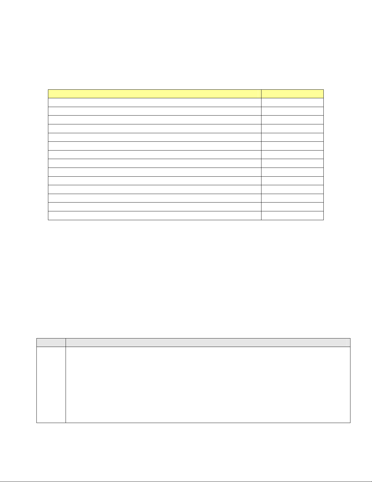
Figure 2: Avaya 30A Switch Base Connections
2. Equipment and Software Validated
The following equipment and software were used for the sample configuration provided:
Equipment Software
Avaya 4602 IP Telephone 1.7
Avaya 4602SW IP Telephone 1.7
Avaya 4610SW IP Telephone 2.0
Avaya 4620 IP Telephone with EU24 Button Expansion Module 2.0
Avaya 4620SW IP Telephone with EU24 Button Expansion Module 2.0
Avaya 4630SW IP Screenphone 1.8
Avaya 4606 IP Telephone (Gen-2) 1.73
Avaya 4612 IP Telephone (Gen-1, Gen-2) 1.73
Avaya 4624 IP Telephone (Gen-1) 1.73
Avaya 4624 IP Telephone (Gen-2) 1.8
Avaya AP 3 Access Point (Version 2) 2.1.2(412)
Avaya AP 5 Access Point 2.1.1(375)
Avaya 30A Ethernet Switch Base 3Com SuperStack 3 Switch 4400-PWR V.3.12
Table 1: Equipment and Software Validated
3. Configure the 3Com SuperStack 3 Switch 4400-PWR
This section describes the configuration steps to control and monitor inline power status. Either
the command line interface (CLI) or the web-based management interface can be used to
accomplish these tasks. These Application Notes demonstrate the configurations using the webbased interface. By default, the switch tries to obtain an IP address from a DHCP or BOOTP
server on the network. If neither server is found, the switch configures itself with its default IP
address 169.254.100.100. In these Application Notes, there is no DHCP server available in the
configuration.
Steps Description
1.
Access the switch using a web browser
• Configure a laptop or PC with an IP address in the 169.254.100.0/24 subnet. Launch a
web browser and point to http://169.254.100.100.
• Log in using the appropriate credentials as shown in Figure 3.
SZ; Reviewed:
WCH 3/19/2004
Solution & Interoperability Test Lab Application Notes
©2004 Avaya Inc. All Rights Reserved.
4 of 14
3com-PoE-Config.doc
Page 5
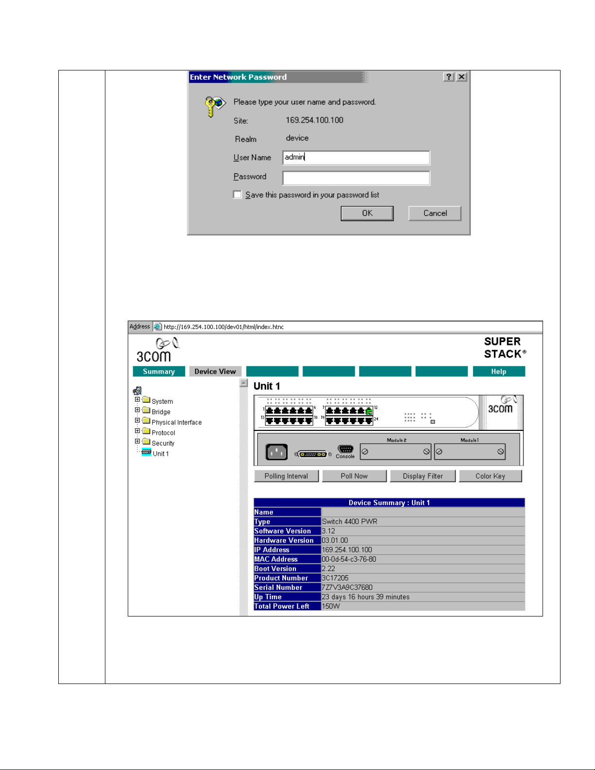
Figure 3: Log in to the Switch
• From the main menu, click Device View to display device information as shown in
Figure 4.
Figure 4: Device View
To access power configuration information, expand the folder Physical interface Æ Power in
the navigation panel as shown in Figure 4.
SZ; Reviewed:
WCH 3/19/2004
Solution & Interoperability Test Lab Application Notes
©2004 Avaya Inc. All Rights Reserved.
5 of 14
3com-PoE-Config.doc
Page 6

2.
Configure switch port inline power
1. Click Device View on the Toolbar.
2. Select Physical Interface -> Power -> Configure in the navigation panel;
3. The following window displays the switch default power configuration.
Figure 5: Port Inline Power Configuration
Note that for all ports, Power State is Inactive and Profile is set to Not Guaranteed, as there
are no Powered Devices (PDs) connected to the switch.
The screen lists the following information for all the switch ports:
Power State
The Power over Ethernet status for that port. This can take one of the following values:
• Active — The port is currently delivering power.
• Inactive — No device is currently requesting power from the port.
SZ; Reviewed:
WCH 3/19/2004
Solution & Interoperability Test Lab Application Notes
©2004 Avaya Inc. All Rights Reserved.
6 of 14
3com-PoE-Config.doc
Page 7

Profile
The Profile that has been selected for a port. This can take one of the following values:
Limited To
The power that has been guaranteed to a device. If no power has been guaranteed, a hyphen
('-') is displayed and the port is limited to 15.4 watts as defined in the Power over Ethernet
specification (IEEE 802.3af-2003).
Current
The power that is currently supplied to a port. If no power is currently supplied, a hyphen ('-')
is displayed.
Peak
The maximum power that has been supplied by a port since the counter was last reset.
The following example can be used to verify that the switch can auto-detect the PDs and
supply power to them.
• Disabled — The port has been configured not to supply power.
• FAULT — The port is in error.
• Guaranteed — The device on the port has power reserved for it, as listed in the Limited
To column.
• Not Guaranteed — The device on the port has no power reserved for it. It will receive
power if the switch is below its maximum power budget, and all ports with higher
priorities are receiving power.
• Plug the Avaya 4620, 4612 and 4602SW IP phones into ports 1-3.
• Click Refresh as shown in Figure 5. Figure 6 shows that all three IP telephones are
automatically powered up, and the power status is changed to Active. Note that the
Current and Peak power for all three IP telephones are displayed also.
SZ; Reviewed:
WCH 3/19/2004
Solution & Interoperability Test Lab Application Notes
©2004 Avaya Inc. All Rights Reserved.
7 of 14
3com-PoE-Config.doc
Page 8

3.
Configure port power profile.
By default, the maximum power for all ports is not guaranteed. To guarantee that PDs get their
specified maximum power, their profile can be configured using the Guaranteed profile.
Guaranteeing Power on a Port
To guarantee power to a port:
In the Port column, select the port or ports that are guaranteed for power.
In the drop-down box:
Or
Repeat for each type of device that needs guaranteed power.
SZ; Reviewed:
WCH 3/19/2004
Figure 6: Display Inline Power Status
• Select the profile that corresponds to the switch ports connecting to that device type.
• Select Guaranteed and enter the maximum power required by the device type in the
text box that appears below.
• Click Apply.
Solution & Interoperability Test Lab Application Notes
©2004 Avaya Inc. All Rights Reserved.
3com-PoE-Config.doc
8 of 14
Page 9

For example, follow the steps above to change ports 1-3 to use the guaranteed profile.
Figure 7 shows all three ports are configured to use the Guaranteed profile. Note the power
limit is set to 15.4 watts for ports 1 and 2, and 7 watts for port 3, since both the 4620 and 4612
IP telephones are class 3 devices and the 4602SW IP phone is a class 1 device.
Table 2 shows the required power allocations defined by IEEE 802.3af-2003, based on the
class.
Class Usage Power
(Watts)
0 Default 15.4
1 optional 4
2 optional 7
3 optional 15.4
Table 2: IEEE 802.3af-2003 Power Classes
SZ; Reviewed:
WCH 3/19/2004
Figure 7: Port Inline Power Profile Configuration
Solution & Interoperability Test Lab Application Notes
©2004 Avaya Inc. All Rights Reserved.
9 of 14
3com-PoE-Config.doc
Page 10

Removing Guaranteed Power from a Port
To remove guaranteed power from a port:
• In the Port column, select the port or ports from which the guaranteed power needs to
be removed.
• Select Not Guaranteed from the drop-down box.
• Click Apply.
Disabling Power on a Port
To disable power on a port:
• In the Port column, select the port or ports for which the power is to be disabled.
• Click Disable.
Enabling Power on a Port
To enable power on a port:
• In the Port column, select the port or ports for which the power is to be enabled.
• Click Enable.
For example, Figure 8 shows the power status for ports 1-3 after disabling inline power.
SZ; Reviewed:
WCH 3/19/2004
Figure 8: Disable Inline Power Configuration
Note the power state for ports 1-3 is changed to Disabled.
Solution & Interoperability Test Lab Application Notes
©2004 Avaya Inc. All Rights Reserved.
10 of 14
3com-PoE-Config.doc
Page 11

4. Verification Steps
The following steps can be used to verify proper connection, configuration, and powering of
Avaya IP telephones.
Steps Description
1.
Disable inline power to port 1 and verify that the telephone loses power.
• In the Port column, select port 1:1 and click Disable as shown in Figure 9.
• Click Refresh for the change to take effect.
Figure 9: Disable Inline Power for Port 1
To view port 1 power status:
• Click Device View on the Toolbar.
• Select Physical Interface -> Power -> Detail in the navigation panel.
• From the Power Detail for Port drop-down box, select port 1.
SZ; Reviewed:
WCH 3/19/2004
Solution & Interoperability Test Lab Application Notes
©2004 Avaya Inc. All Rights Reserved.
11 of 14
3com-PoE-Config.doc
Page 12

2.
The following window is displayed:
Figure 10: Display Port 1 Power Status
Note that the power state is Disabled as shown in Figure 10.
Enable inline power for port 1 and verify that the telephone receives power.
• In the Port column, select port 1:1 and click Enable.
• Click Refresh for the change to take effect.
• Select Physical Interface -> Power -> Detail in the navigation panel.
• From the Power Detail for Port drop-down box, select port 1.
SZ; Reviewed:
WCH 3/19/2004
Solution & Interoperability Test Lab Application Notes
©2004 Avaya Inc. All Rights Reserved.
12 of 14
3com-PoE-Config.doc
Page 13

The following window is displayed. Note that the power state has changed to Active as shown in
Figure 11.
Figure 11: Port 1 Power is enabled
5. Conclusion
The following Avaya IP telephones and wireless LAN access points were tested with the 3Com
SuperStack 3 Switch 4400-PWR inline power switch, and were successfully powered:
• IP telephones:
• 4602 and 4602SW
• 4610SW
• 4620 and 4620SW, including EU24 Button Expansion Module
• 4630SW
• Gen-1 4612 and 4624 with 30A switch base
• Gen-2 4606, 4612, and 4624
• Wireless LAN access points
• AP 3
• AP 5
SZ; Reviewed:
WCH 3/19/2004
Solution & Interoperability Test Lab Application Notes
©2004 Avaya Inc. All Rights Reserved.
13 of 14
3com-PoE-Config.doc
Page 14

©
2004 Avaya Inc. All Rights Reserved.
Avaya and the Avaya Logo are trademarks of Avaya Inc. All trademarks identified by ® and ™
are registered trademarks or trademarks, respectively, of Avaya Inc. All other trademarks are the
property of their respective owners. The information provided in these Application Notes is
subject to change without notice. The configurations, technical data, and recommendations
provided in these Application Notes are believed to be accurate and dependable, but are
presented without express or implied warranty. Users are responsible for their application of any
products specified in these Application Notes.
Please e-mail any questions or comments pertaining to these Application Notes along with the
full title name and filename, located in the lower right corner, directly to the Avaya Solution &
Interoperability Test Lab at interoplabnotes@list.avaya.com
SZ; Reviewed:
WCH 3/19/2004
Solution & Interoperability Test Lab Application Notes
©2004 Avaya Inc. All Rights Reserved.
14 of 14
3com-PoE-Config.doc
 Loading...