

Avaya IP Office 3.2 Phone Installation Guide

IP Office 3.2
Phone Installation Guide
15-601042 Issue 11e (27th June 2006)

© 2006 Avaya Inc. All Rights Reserved.
Notice
While reasonable efforts were made to ensure that the information in this document was complete and accurate at the time of
printing, Avaya Inc. can assume no liability for any errors. Changes and corrections to the information in this document may be
incorporated in future releases.
Documentation Disclaimer
Avaya Inc. is not responsible for any modifications, additions, or deletions to the original published version of this documentation
unless such modifications, additions, or deletions were performed by Avaya.
Link Disclaimer
Avaya Inc. is not responsible for the contents or reliability of any linked Web sites referenced elsewhere within this
Documentation, and Avaya does not necessarily endorse the products, services, or information described or offered within
them. We cannot guarantee that these links will work all of the time and we have no control over the availability of the linked
pages.
License
USE OR INSTALLATION OF THE PRODUCT INDICATES THE END USER’S ACCEPTANCE OF THE TERMS SET FORTH
HEREIN AND THE GENERAL LICENSE TERMS AVAILABLE ON THE AVAYA WEBSITE AT
http://support.avaya.com/LicenseInfo/
(“GENERAL LICENSE TERMS”). IF YOU DO NOT WISH TO BE BOUND BY THESE
TERMS, YOU MUST RETURN THE PRODUCT(S) TO THE POINT OF PURCHASE WITHIN TEN (10) DAYS OF DELIVERY
FOR A REFUND OR CREDIT.
Avaya grants End User a license within the scope of the license types described below. The applicable number of licenses and
units of capacity for which the license is granted will be one (1), unless a different number of licenses or units of capacity is
specified in the Documentation or other materials available to End User. “Designated Processor” means a single stand-alone
computing device. “Server” means a Designated Processor that hosts a software application to be accessed by multiple users.
“Software” means the computer programs in object code, originally licensed by Avaya and ultimately utilized by End User,
whether as stand-alone Products or pre-installed on Hardware. “Hardware” means the standard hardware Products, originally
sold by Avaya and ultimately utilized by End User.
License Type(s): Designated System(s) License (DS).
End User may install and use each copy of the Software on only one Designated Processor, unless a different number of
Designated Processors is indicated in the Documentation or other materials available to End User. Avaya may require the
Designated Processor(s) to be identified by type, serial number, feature key, location or other specific designation, or to be
provided by End User to Avaya through electronic means established by Avaya specifically for this purpose.
Copyright
Except where expressly stated otherwise, the Product is protected by copyright and other laws respecting proprietary rights.
Unauthorized reproduction, transfer, and or use can be a criminal, as well as a civil, offense under the applicable law.
Third-Party Components
Certain software programs or portions thereof included in the Product may contain software distributed under third party
agreements (“Third Party Components”), which may contain terms that expand or limit rights to use certain portions of the
Product (“Third Party Terms”). Information identifying Third Party Components and the Third Party Terms that apply to them is
available on Avaya’s web site at: http://support.avaya.com/ThirdPartyLicense/
Avaya Fraud Intervention
If you suspect that you are being victimized by toll fraud and you need technical assistance or support, call Technical Service
Center Toll Fraud Intervention Hotline at +1-800-643-2353 for the United States and Canada. Suspected security vulnerabilities
with Avaya Products should be reported to Avaya by sending mail to: securityalerts@avaya.com.
For additional support telephone numbers, see the Avaya Support web site (http://www.avaya.com/support).
Trademarks
Avaya and the Avaya logo are registered trademarks of Avaya Inc. in the United States of America and other jurisdictions.
Unless otherwise provided in this document, marks identified by “®,” “™” and “
SM”
are registered marks, trademarks and service
marks, respectively, of Avaya Inc. All other trademarks are the property of their respective owners.
Documentation information
For the most current versions of documentation, go to the Avaya Support web site (http://www.avaya.com/support) or the IP
Office Knowledge Base (http://marketingtools.avaya.com/knowledgebase/).
Avaya Support
Avaya provides a telephone number for you to use to report problems or to ask questions about your contact center. The
support telephone number is 1- 800- 242- 2121 in the United States. For additional support telephone numbers, see the Avaya
Web site: http://www.avaya.com/support.

Phone Installation Guide Page iii
IP Office 3.2 15-601042 Issue 11e (27th June 2006)
Table of Contents
IP Office IP Phones .................................................................................................................... 1
Introduction................................................................................................................................................. 1
Small Installation (5 or less phones)........................................................................................................... 3
Large Installation (More than 5 phones)..................................................................................................... 4
Wireless Installation.................................................................................................................................... 5
Installation Requirements ........................................................................................................................... 6
Network Assessment.................................................................................................................................. 7
Voice Compression Channels .................................................................................................................... 8
QoS ............................................................................................................................................................ 8
Potential VoIP Problems............................................................................................................................. 9
User PC Connection................................................................................................................................. 10
Power Supply Options .............................................................................................................................. 11
Spare Wire Power Options .................................................................................................................. 11
802.3af Power over Ethernet Options.................................................................................................. 12
TFTP Options ........................................................................................................................................... 13
TFTP Introduction ................................................................................................................................ 13
Using a Control Unit Memory Card for TFTP.......................................................................................14
TFTP Application ................................................................................................................................. 15
Installation ................................................................................................................................ 17
1. Preparation ........................................................................................................................................... 17
1a. 4601 and 5601 Installation ................................................................................................................. 18
1b. Creating a 46xxsettings.txt File .......................................................................................................... 18
2. Phone Connection ................................................................................................................................ 19
3a. DHCP Address Installation ................................................................................................................. 19
3b. Static Address Installation .................................................................................................................. 20
4. Phone Registration ............................................................................................................................... 21
5. Extension & User Setup ....................................................................................................................... 21
Manually Creating Extensions .................................................................................................................. 22
Phone Security ......................................................................................................................................... 23
Listing Registered Phones........................................................................................................................ 23
Static Administration............................................................................................................... 25
Static Administration Options ................................................................................................................... 25
Entering Data for Administrative Options ................................................................................................. 25
QoS Option Settings................................................................................................................................. 26
Secondary Ethernet (Hub)/IR Interface Enable/Disable ........................................................................... 26
Appendix A: Miscellaneous .................................................................................................... 27
Error Messages ........................................................................................................................................ 27
View Administrative Details ...................................................................................................................... 28
Reset System Values ............................................................................................................................... 29
Self-Test Procedure.................................................................................................................................. 29
Site Specific Option Number .................................................................................................................... 30
Automatic Gain Control ............................................................................................................................ 30
Appendix B: IP Telephone Files ............................................................................................. 31
IP Telephone Files.................................................................................................................................... 31
The 46XX Upgrade Script File.................................................................................................................. 32
The 46XX Settings Script File................................................................................................................... 32
46XX Settings ...................................................................................................................................... 33
Appendix C: Scenarios for the Restart Process ................................................................... 35
Restart Scenarios ..................................................................................................................................... 35
Boot File Needs Upgrading ...................................................................................................................... 36
No Application File or Application File Needs Upgrading .........................................................................37
Correct Boot File and Application File Already Loaded ............................................................................ 37

IP Phone Installation Manual
Phone Installation Guide Page iv
IP Office 3.2 15-601042 Issue 11e (27th June 2006)
Appendix D: Infrared Dialling.................................................................................................. 39
Infrared Dialling ........................................................................................................................................ 39
Enabling the IR Port ................................................................................................................................. 40
Dialling Phone Numbers........................................................................................................................... 40
Palm Organizer .................................................................................................................................... 40
Windows Pocket PC ............................................................................................................................ 41
Beaming Files During a Call ..................................................................................................................... 41
Palm Organizer .................................................................................................................................... 41
Appendix E: Alternate DHCP Setup........................................................................................ 43
Alternate DHCP Servers for Avaya IP Phone Installation ........................................................................ 43
Using Windows 2000 Server .................................................................................................................... 43
1. Checking for DHCP.......................................................................................................................... 43
2. Windows 2000 DHCP Setup for H.323 IP Phones .......................................................................... 44
Alternate Options...................................................................................................................................... 46
Appendix F: WML Operation................................................................................................... 47
WML Server Setup ................................................................................................................................... 47
What WML is Supported ...................................................................................................................... 47
Testing WML Browsing Using Xitami ....................................................................................................... 48
1. Introduction ...................................................................................................................................... 48
2. Installing the Web Server................................................................................................................. 48
3. Configuring the Xitami Web Server for WAP ................................................................................... 48
4. Installing Sample WML Pages ......................................................................................................... 49
Setting the Home Page ............................................................................................................................ 50
Apache Web Server WML Configuration.................................................................................................. 51
Microsoft IIS Web Server WML Configuration.......................................................................................... 51
Open URL Entry ....................................................................................................................................... 52
Case 1. Input Box Followed by an Anchor Tag.................................................................................... 52
Case 2. Input Box Followed by an A Tag............................................................................................. 52
Case 3. Input Box Followed by a Submit Button.................................................................................. 52
Case 4. Input Box Followed by an Anchor Tag Where the Anchor Tag Already Displays HTTP:// ..... 52
Appendix G: 3616/3620/3626 Installation............................................................................... 53
3616/3620/3626 Spectralink Installation................................................................................................... 53
Access Points ........................................................................................................................................... 53
Index.......................................................................................................................................... 55

Phone Installation Guide Page 1
IP Office 3.2 15-601042 Issue 11e (27th June 2006)
IP Office IP Phones
Introduction
This guide covers the installation of Avaya H.323 IP phones on IP Office systems. Currently, the
following H.323 IP phones are supported on IP Office 3.2.
H.323 IP
Phones
Models Note
4600 Series
4601, 4602, 4602SW,
4606, 4610SW, 4612,
4620, 4620SW, 4621SW
4624, 4625.
These are H.323 IP phones supported on a
number of Avaya phone systems.
5600 Series
5601, 5602, 5602SW,
5610SW, 5620, 5620SW,
5621.
These are H.323 IP phones that are supported
on IP Office only.
3600 Series
3616, 3620 and 3626. These are 801.11b wireless H.323 IP phones.
They work with a Avaya Voice Priority Processor
(AVPP) unit and a range of wireless Access
Points.
PC
Softphone
IP Office Phone Manager
Pro PC Softphone.
This is a VoIP enabled installation of the IP Office
Phone Manager software. It is not covered in this
manual. Refer to the Phone Manager Installation
and Maintenance Manual for details.
Other H.323 IP telephony devices are supported through the entry of an IP Office IP Endpoint license
into the IP Office configuration. However, no functionality on these devices beyond basic call answering
and making is guaranteed by Avaya. Therefore, installation of these devices should be thoroughly tested
before any customer deployment.
The maximum number of H.323 IP phone devices supported by any IP Office system is based on that
system's maximum capacity for extensions of any type, minus the number of non-IP extensions installed
on the control unit and any expansion modules. The number of simultaneous calls between IP and nonIP devices will also be limited by the number of VCM channels installed in the IP Office unit.
IP Office
Unit
Maximum
Extensions
Maximum
VCM Channels
Small Office Edition 28 3 or 16
IP403 100 20
IP406 V1 180 20
IP406 V2 190 30
IP412 360 60

IP Phone Installation Manual
Phone Installation Guide Page 2
IP Office 3.2 15-601042 Issue 11e (27th June 2006)
Notes
• IP Phone Software Version
H.323 IP phones on an IP Office system must
use the IP Phone software installed with the IP
Office Manager application. Other versions of IP Phone software may not have been tested with
IP Office and so should not be used unless IP Office support is specifically mentioned in their
accompanying documentation.
• DHCP versus Static IP Installation
Though static IP installation of H.323 IP phones is possible, installation using DHCP is strongly
recommended. The use of DHCP eases both the installation process and future maintenance
and administration. In addition, following a boot file upgrade, all static address settings are lost
and must be re-entered.
• Network Assessment
High quality voice transmission across an IP network requires careful assessment of many
factors. Therefore:
• We strongly recommend that IP phone installation is only done by installers with VoIP
experience.
• The whole customer network must be assessed for its suitability for VoIP, before
installation. Avaya may refuse to support any installation where the results of a network
assessment cannot be supplied.
IP Office IP Phones
Phone Installation Guide Page 3
IP Office 3.2 15-601042 Issue 11e (27th June 2006)
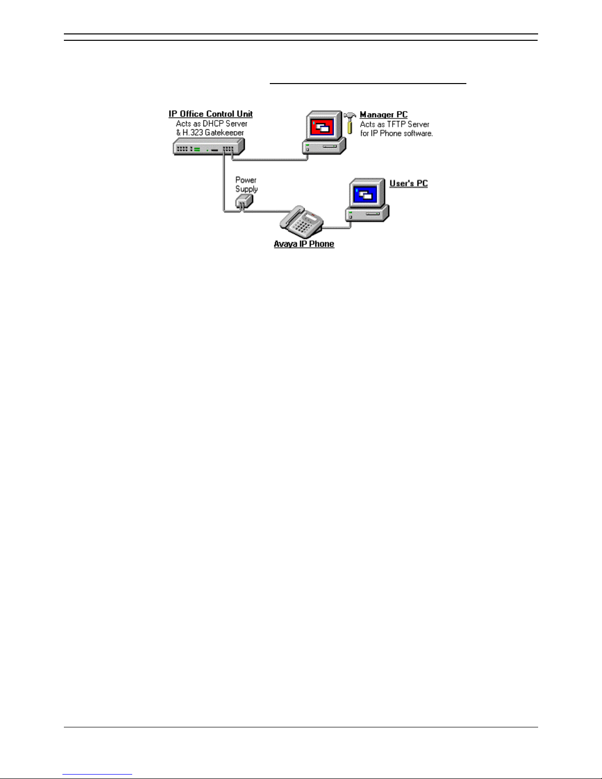
Small Installation (5 or less phones)
The diagram below shows the simplest installation scenario, suitable when only a few H.323 IP phones
are being installed. This type of installation is only supported for up to 5 IP phone devices
.
• DHCP Server
The IP Office unit is acting as the DHCP server for the H.323 IP phones.
• For scenarios where the customer already has a DHCP server or wants to use an
alternate DHCP server, details of configuring 3-party DHCP servers to support H.323 IP
phones are included. See Large Installation.
• H.323 Gatekeeper
The IP Office unit is acting as the H.323 Gatekeeper for the H.323 IP phones.
• TFTP Server
The IP Office Manager application is acting as the TFTP server used to provide the H.323 IP
phones with appropriate software for operation on the IP Office system.
• In this instance, the Manager application is only being run to perform its TFTP role during
the installation process. Once installed, the H.323 IP phones look for a TFTP server
whenever restarted but will eventually restart if no TFTP server is found.
• If a permanent TFTP server is required, use of IP Office Manager is not recommended.
Details of TFTP Server Options are included in the installation process.
IP Phone Installation Manual
Phone Installation Guide Page 4
IP Office 3.2 15-601042 Issue 11e (27th June 2006)
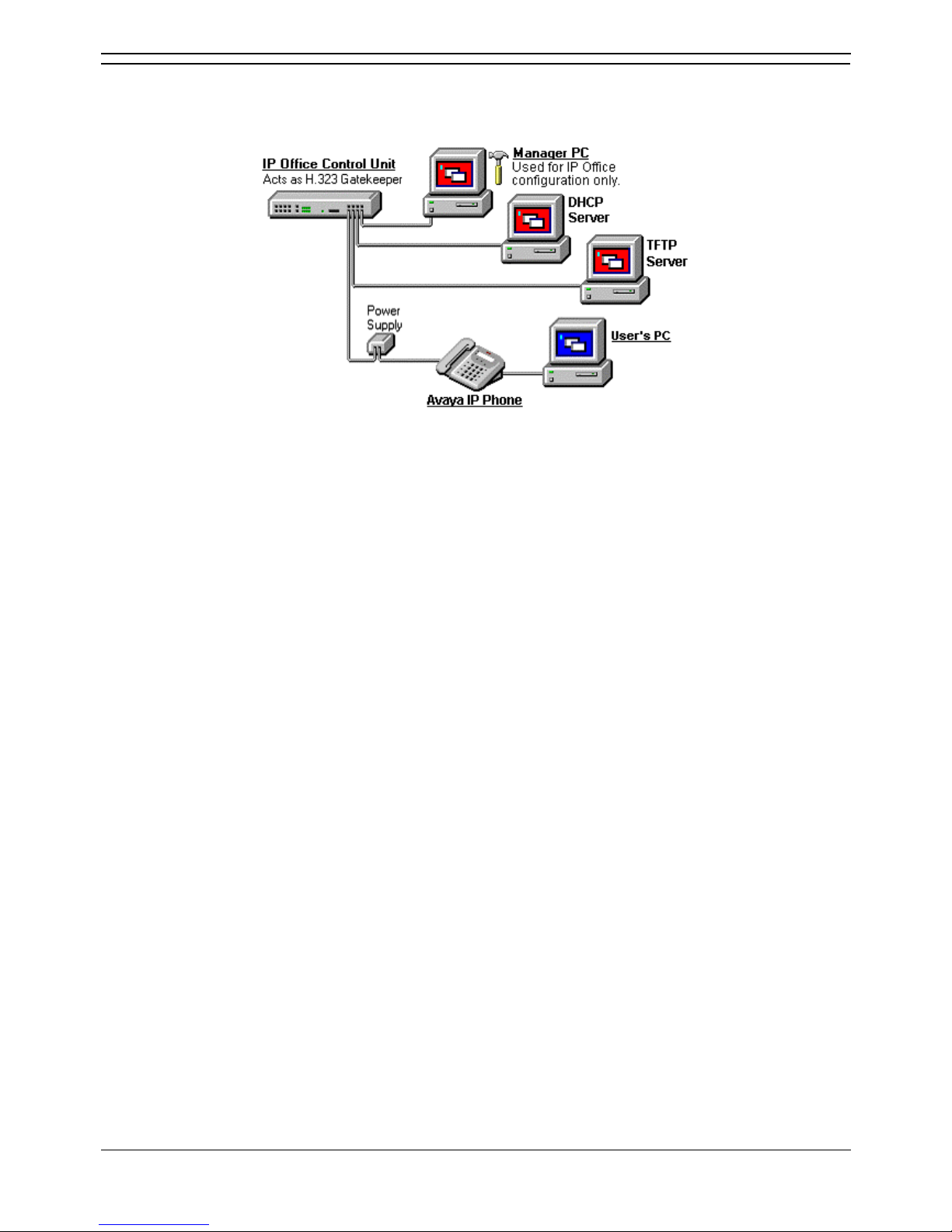
Large Installation (More than 5 phones)
The diagram below shows a scenario where more than 5 IP phone devices are being supported. In this
scenario, the DHCP and TFTP roles must be changed from those used in a small installation.
• DHCP Server
In this scenario, a separate DHCP server is being used. This requires that the DHCP function of
the IP Office unit is switched off. Therefore the IP Office unit must be given a fixed IP address (or
act as a DHCP client). Details of using a Windows 2000 DHCP Server are included in this
documentation but those details are applicable to most DHCP servers.
• H.323 Gatekeeper
The IP Office unit is acting as the H.323 Gatekeeper for the H.323 IP phones.
• TFTP Server
In this instance, the Manager role as TFTP server must be replaced by an alternative TFTP
Server option. The installation process includes details for doing this in several ways:
• On Small Office Edition and IP406 V2 units, a memory card in the Embedded Voicemail
Memory card slot can be used as the TFTP folder.
• A 3rd party TFTP application can be installed and used.
IP Office IP Phones
Phone Installation Guide Page 5
IP Office 3.2 15-601042 Issue 11e (27th June 2006)
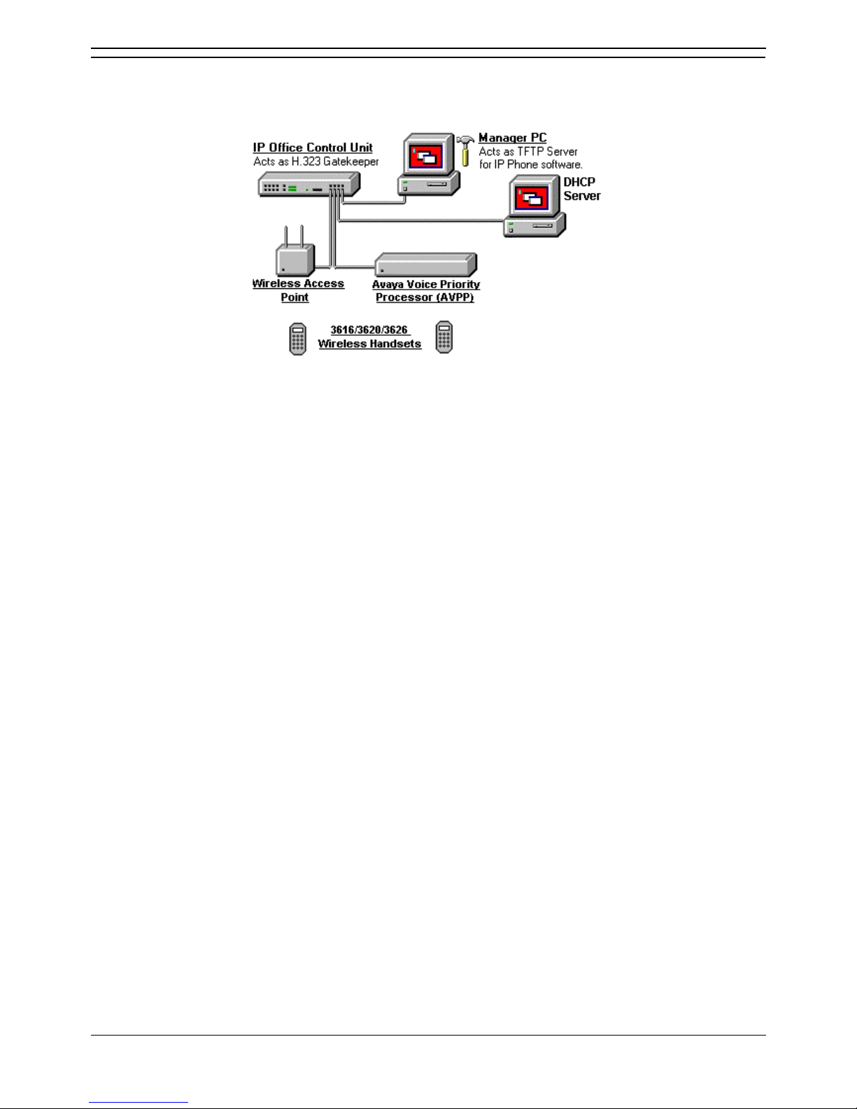
Wireless Installation
The diagram below shows a scenario where Avaya 3616, 3620 and 3626 802.11b wireless H.323 IP
phones are supported.
• DHCP Server
The rules about the use of the IP Office as a DHCP server or the use of a separate DHCP server
still apply. If more than 5 H.323 IP phones are being supported, a separate DHCP server must be
used.
• H.323 Gatekeeper
The IP Office unit is acting as the H.323 Gatekeeper for the H.323 IP phones.
• TFTP Server
The rules about the use of the IP Office Manager as a TFTP server still apply. If more than 5
H.323 IP phones are being supported, a separate TFTP server must be used.
• Avaya Voice Priority Processor (AVPP)
The IP address of the AVPP is entered into the IP Office configuration. This unit applies a
mechanism called Spectralink Voice Priority (SVP) to the wireless voice packets.
• Wireless Access Point
A number of different wireless Access Points have been tested for compliance with the SVP
mechanism applied by the AVPP. Those Access Points are listed in Appendix G:
3616/3620/3626 Installation.

IP Phone Installation Manual
Phone Installation Guide Page 6
IP Office 3.2 15-601042 Issue 11e (27th June 2006)
Installation Requirements
To install an IP phone on IP Office, the following items are required:
• Extension Number and User Details:
A full listing of the planned extension number and user name details is required. The planned
extension number must be unused and is requested by the phone during installation.
• Power Supply:
Each phone requires a power supply. H.323 IP phones do not draw power from the phone switch.
A number of options exist for how power is supplied to the phones. See Power Supply Options.
• LAN Socket:
An RJ45 Ethernet LAN connection point is required for each phone.
• Category 5 Cabling:
All LAN cables and LAN cable infrastructure used with H.323 IP phones should
use CAT5
cabling. Existing CAT3 cabling may be used but will be limited to 10Mbps (maximum).
• LAN Cables:
Check that an RJ45 LAN cable has been supplied with the IP phone for connection to the power
supply unit. You will also need an additional RJ45 LAN cable for connection from the power unit
to the customer LAN.
• A further RJ45 LAN cable can be used to connect the user's PC to the LAN via the IP
phone [not supported on 4601, 4602, 5601 and 5602 H.323 IP phones].
• Voice Compression Module:
The IP Office Unit must have voice compression channels available. The number of voice
compression channels limits the number of simultaneous VoIP calls:
• On Small Office Edition units, either 3 or 16 voice compression channels are pre-built into
the unit.
• On all other control units, voice compression channels are provided by fitting a Voice
Compression Module.
• DHCP Server:
The IP Office Unit can perform this role for up to 5 IP phone devices. If another DHCP server
already exists, this may be able to do DHCP for the H.323 IP phones, see Alternate DHCP
Servers. Static IP addressing can also be used, if required, but is not recommended.
• TFTP Server:
A PC running the IP Office Manager application can perform this role for up to 5 H.323 IP
phones. Otherwise one of the other TFTP Server Options must be used.
• H323 Gatekeeper:
The IP Office Unit performs this role.
• IP Office Manager PC:
A PC running Manager is required for IP Office Unit configuration changes. This PC should have
a static IP address.
• IP Telephone Software:
The software for IP phone installation is installed into the IP Office Manager program folder
during Manager installation.
• Licence Keys:
IP Office supported H.323 IP phones do not need a licence key entered on the system.

IP Office IP Phones
Phone Installation Guide Page 7
IP Office 3.2 15-601042 Issue 11e (27th June 2006)
Network Assessment
WARNING
• A Network Assessment is Mandatory
When installing H.323 IP phones on an IP Office system, it is assumed by Avaya that a network
assessment has been performed. If a support issue is escalated to Avaya, Avaya may request to
see the results of the network assessment and may refuse to provide support if a suitable
network assessment was not performed.
Current technology allows optimum network configurations to deliver VoIP with voice quality close to that
of the public phone network. However, few networks are optimum and so care should be taken
assessing the VoIP quality achievable across a customer network.
Not every network is able to carry voice transmissions. Some data networks have insufficient capacity for
voice traffic or have data peaks that will impact voice traffic on occasion. In addition, the usual history of
growing and developing networks by integrating products from many vendors makes it necessary to test
all the network components for compatibility with VoIP traffic.
A network assessment would include a determination of the following:
• A network audit to review existing equipment and evaluate its capabilities, including its ability to
meet both current and planned voice and data needs.
• A determination of network objectives, including the dominant traffic type, choice of technologies
and setting voice quality objectives.
• The assessment should leave you confident that the implemented network will have the capacity
for the foreseen data and voice traffic, and can support H.323, DHCP, TFTP and jitter buffers in
H.323 applications.
• An outline of the expected network assessment targets is:
Test Minimum Assessment Target
Latency Less than 150ms.
Packet Loss Less than 2%.
Duration Monitor statistics once every minute for a full week.

IP Phone Installation Manual
Phone Installation Guide Page 8
IP Office 3.2 15-601042 Issue 11e (27th June 2006)
Voice Compression Channels
IP Office Voice Compression Channels are used when a voice call goes between a device on the IP
Office's data network (that is, an IP trunk or extension) and a device on the IP Office's TDM telephony
interface (that is, a non-IP trunk or extension).
When using Direct Media (the default), calls between IP device (trunks or extensions) do not normally
need a Voice Compression Channel once the call is connected. However, they do use a VCM channel
for call signalling tones, music-on-hold, etc.
Voice Compression Channels are provided by installing a VCM card into the IP Office unit. These cards
are available in a number of different capacities (i.e. number of Voice Compression Channels). The
maximum capacity of an IP Office system depends on the unit type as follows:
IP Office Unit Voice Compression Channel Capacity
Small Office
Edition
Supplied with either 3 or 16 VCM channels pre-built into the unit. These cannot be
upgraded.
IP403 Supports a single VCM card with up to 20 channels.
IP406 V1 Supports a single VCM card with up to 20 channels.
IP406 V2 Supports a single VCM card with up to 30 channels.
IP412 Supports any two VCM cards totalling up to 60 channels.
The Voice Compression Channels support G.723 (6k3) and G.729a (8k) compression codecs and
provide echo cancellation for high latency circuits. H.323 IP phones support G.711, G.729a and G.729b,
thus G.729a is normally auto-negotiated when these phones are used on IP Office.
VCM cards exist with the following capacities.
• VCM 5, VCM 10, VCM 20 and VCM 30: these cards support 25ms echo cancellation.
• VCM 4, VCM 8, VCM 16 and VCM 24: these cards support 64ms echo cancellation.
QoS
When transporting voice over low speed links it is possible for normal data packets (1500 byte packets)
to prevent or delay voice packets (typically 67 or 31 bytes) from getting across the link. This can cause a
very unacceptable speech quality.
Therefore, it is vital that all traffic routers and switches in the network to have some form of Quality of
Service (QoS) mechanism. QoS routers are essential to ensure low speech latency and to maintain
sufficient audible quality.
IP Office supports the DiffServ (RFC2474) QoS mechanism. This is based upon using a Type of Service
(ToS) field in the IP packet header. On its WAN interfaces, IP Office uses this to prioritize voice and
voice signalling packets. It also fragments large data packets and, where supported, provides VoIP
header compression to minimize the WAN overhead.
Note
• IP Office does not perform QoS for its Ethernet ports including the WAN Ethernet port on the
Small Office Edition.

IP Office IP Phones
Phone Installation Guide Page 9
IP Office 3.2 15-601042 Issue 11e (27th June 2006)
Potential VoIP Problems
It is likely that any fault on a network, regardless of its cause, will initially show up as a degradation in the
quality of VoIP operation. This is regardless of whether the fault is with the VoIP telephony equipment.
Therefore, by installing a VoIP solution, you must be aware that you will become the first point of call for
diagnosing and assessing all potential customer network issues.
Potential Problems
• End-to-End Matching Standards:
VoIP depends upon the support and selection of the same voice compression, header
compression and QoS standards throughout all stages of the calls routing. The start and end
points must be using the same compression methods. All intermediate points must support
DiffServ QoS.
• Avoid Hubs:
Hubs introduce echo and congestion points. If the customer network requires LAN connections
beyond the capacity of the IP Office Unit itself, Ethernet switches should be used. Even if this is
not the case, Ethernet switches are recommended as they allow traffic prioritization to be
implemented for VoIP devices and for other device such as the Voicemail Server PC.
• Power Supply Conditioning, Protection and Backup:
Traditional phone systems provide power to all their attached phone devices from a single
source. In a VoIP installation, the same care and concern that goes into providing power
conditioning, protection and backup to the central phone system, must now be applied to all
devices on the IP network.
• Multicasting:
In a data only network, it is possible for an incorrectly installed printer or hub card to multicast
traffic without that fault being immediately identified. On a VoIP network incorrect multicasting will
quickly affect VoIP calls and features.
• Duplicate IP Addressing:
Duplicate addresses is a frequent issue.
• Excessive Utilization:
A workstation that constantly transmits high traffic levels can flood a network, causing VoIP
service to disappear.
• Network Access:
An IP network is much more open to users connecting a new device or installing software on
existing devices that then impacts on VoIP.
• Cabling Connections:
Technically VoIP can (bandwidth allowing) be run across any IP network connection. In practice,
Cat5 cabling is essential.
IP Phone Installation Manual
Phone Installation Guide Page 10
IP Office 3.2 15-601042 Issue 11e (27th June 2006)
User PC Connection
To simplify the number of LAN connections from the user's desk, it is possible to route their PC Ethernet
LAN cable via some H.323 IP phones. The LAN cable should be connected from the PC to the socket
with a PC symbol (
) at the back of the IP phone. The PC's network configuration does not need to be
altered from that which it previously used for direct connection to the LAN.
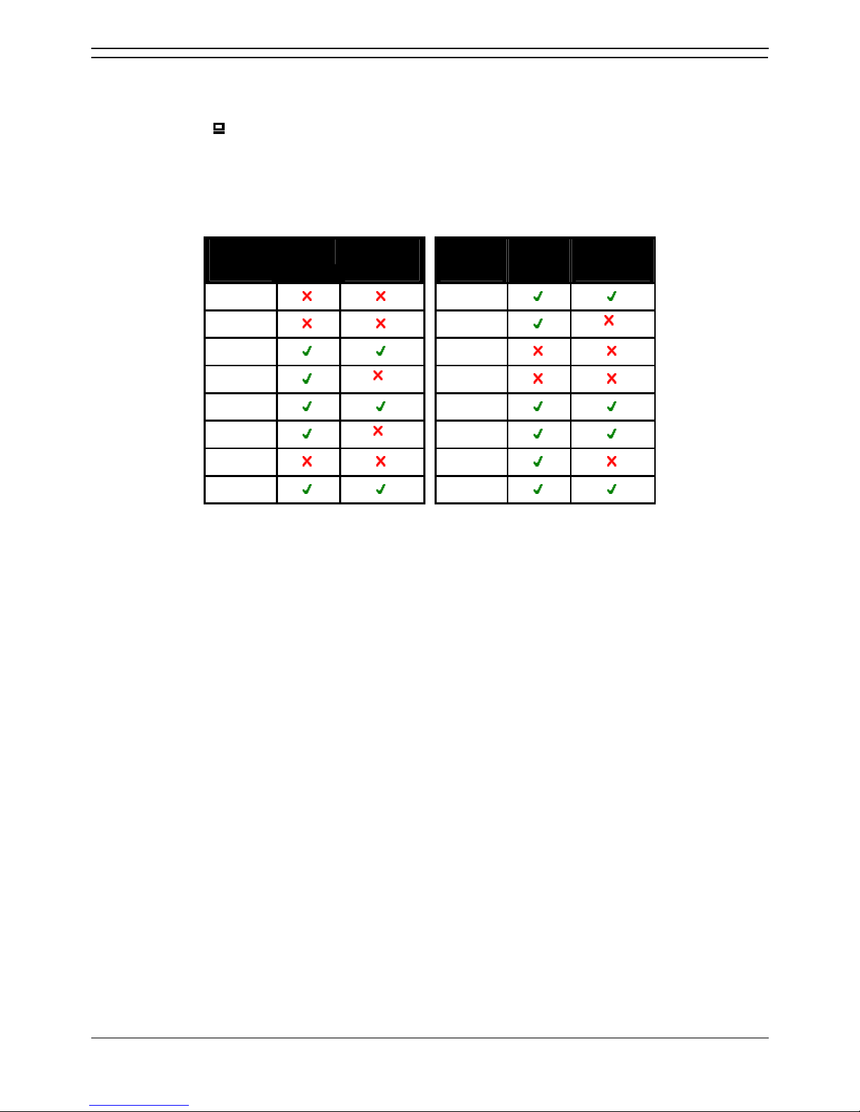
Those phones that include a PC pass-through port and also provide priority to phone voice traffic over
PC data traffic are normally indicated by an SW suffix on the phone name. In addition, some phones
have a PC pass-through port but do not provide switching priority. The table below summarizes the
phones:
H.232
IP Phone
PC Port With Voice
Priority
H.232
IP Phone
PC Port With Voice
Priority
4601
4621
4602
4624
*
4602SW
5601
4606
* 5602
4610SW
5602SW
4612
* 5610SW
4620IP
5620
4620SW
5620SW
• *The 4606, 4612 and 4624 phones can be upgraded to provide voice priority switching by fitting
an Avaya 30A Switch Upgrade Base to the phone. In addition, this base also allows the phone to
be powered from a IEEE 802.3af Power over Ethernet source.
IP Office IP Phones
Phone Installation Guide Page 11
IP Office 3.2 15-601042 Issue 11e (27th June 2006)
Power Supply Options
Each H.323 IP phone requires a power supply. They do not draw power from the IP Office phone
system. Listed below are the power supply options that can be used.
Note
• For phones being used with an EU24 or EU24BL unit, an 1151C1 or 1151C2 must be used. Use
with an EU24 or EU24BL, adds less than 1W. This also applies for 4621SW being used with a
backlight.
Phone Typical Worst Case IEEE 802.3af
4601, 4602, 5601, 5602 3.5W 4.6W Class 2
4602SW, 5602SW 4.1W 5.0W Class 2
4606, 4612, 4624 4.1W 5.0W Class 0
4610SW, 5610 4.0W 6.0W Class 2
4620 7.7W 9.9W Class 3
4621SW 5.9W 8.0W Class 3
4625SW 4.9W 6.45W Class 3
Spare Wire Power Options
The following power supplies use the normally unused pin 7 & 8 connections in the CAT3 or CAT5
network cable. This is referred to as "spare wire" or "mid-span" power supply units.
• Avaya 1151C1 Power Supply Unit (PSU)
A power supply unit for a single IP phone. Has a LINE port for the LAN cable from the IP Office,
and a PHONE port for the LAN cable to the IP phone. Power into the PSU requires a 90 to 264V
AC, 47 to 63HZ mains supply. A green LED indicates when power is available.
• Avaya 1151C2 Power Supply Unit
Same as the 1151C1 above but with integral battery backup. When AC mains supply is removed,
the battery will power the IP phone for between 8 hours at light load (2 Watts) and 15 minutes at
full load (20 Watts). A green LED indicates when power is available. A yellow LED indicates
when the backup is charging. The green LED flashes when the phone is running from the backup
battery.
IP Phone Installation Manual
Phone Installation Guide Page 12
IP Office 3.2 15-601042 Issue 11e (27th June 2006)
802.3af Power over Ethernet Options
IEEE 802.3af is a standard commonly known as Power over Ethernet (PoE). It allows network devices to
receive power via the network cable using the same wires as the data signals. All the H.323 IP phones
supported on IP Office also support this standard.
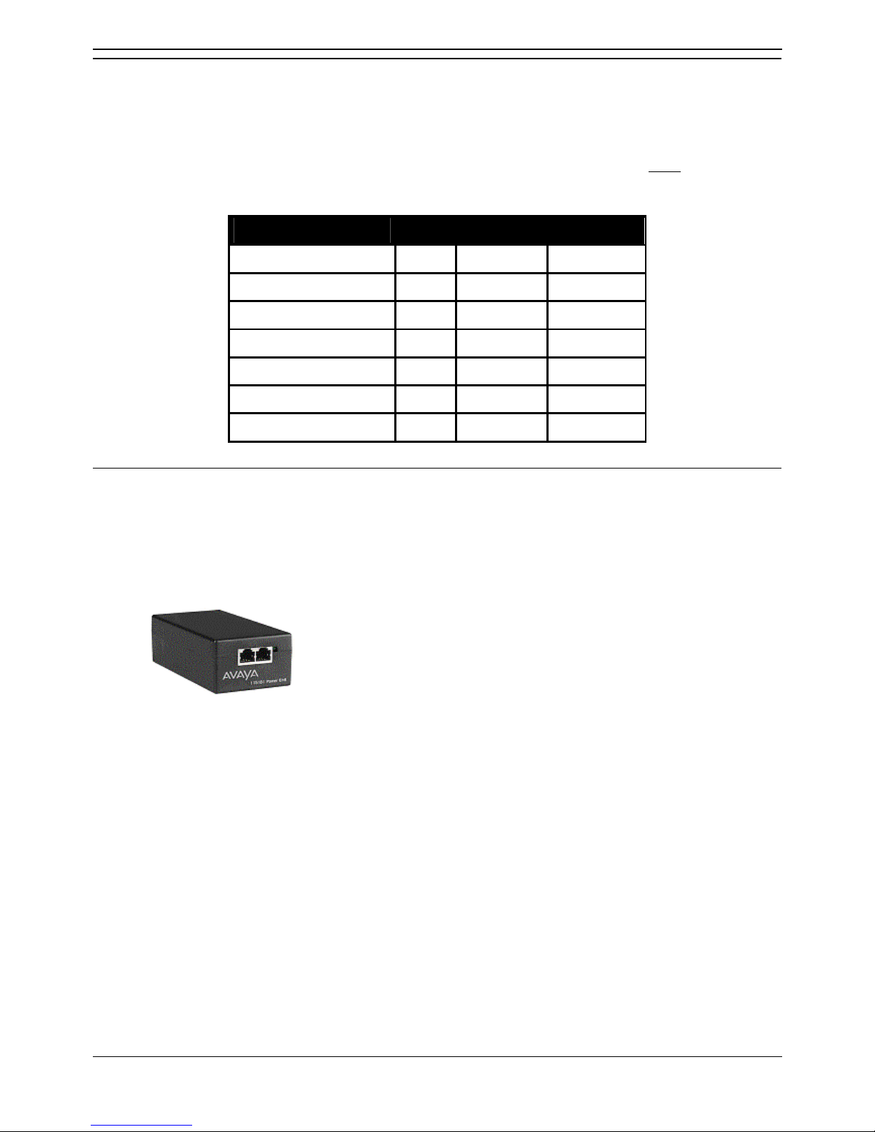
• Avaya 1152A1 Power Distribution Unit (Mid-Span Power Unit)
This is a 1U high 19-inch rack mountable unit. It is available in models to support 6, 12 or 24 PoE
devices including H.323 IP phones. For each device, it provides a RJ45 data in ports and a
matching RJ45 data and power out port. It can support a maximum of 200 Watts or a peak of
16.8 Watts per port.
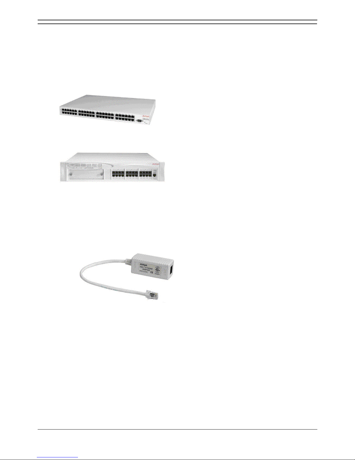
• Power of Ethernet (POE) Switch
The Avaya P333T-PWR Switch is a Ethernet LAN switch which also provides PoE input for up to
24 devices including H.323 IP phones.
• IP Phone Inline Adaptor
This adaptor allows 4602, 4602SW, 4620, 4621 and 4625 H.323 IP phones and 5600 Series
equivalents to be powered from a Cisco Catalyst power blade. Using these adaptors, up to 24
H.323 IP phones can be supported on a single power blade.
Note
• The phones do not provide the Catalyst switch with information on their power
requirements and future changes to Catalyst switch software may affect operation.
*4606, 4612 and 4624 Phones
GEN1 versions of these phones cannot use PoE. The GEN of a phone can be determined from the label
on the base of the phone. The label text giving the phone's type, for example 4624D, is followed by two
digits which give its generation (GEN) number, for example 4624D01. GEN1 4612 and 4624 phones can
be Ethernet powered using a 30A Switch Upgrade Base unit.

IP Office IP Phones
Phone Installation Guide Page 13
IP Office 3.2 15-601042 Issue 11e (27th June 2006)
TFTP Options
TFTP Introduction
In order to load and upgrade their operation software, IP phones search for a TFTP server loaded with
the appropriate files whenever they are restarted.
• If using DHCP, the TFTP server address is set as part of the DHCP options. In the case of the IP
Office being used as the DHCP server, this is done by setting the TFTP Server IP Address in
the IP Office configuration (System | System).
• If not using DHCP, the TFTP server address is entered as part of the static address installation of
each phone.
• A fixed address for the TFTP server is required. However, the TFTP server does not need to be
running permanently. If the phones restart and the TFTP server is not present, they will
eventually timeout waiting for a TFTP response from the server.
The following options are available for TFTP servers:
1. IP Office Manager
When running, the IP Office Manager acts as a TFTP server. TFTP activity is shown in its TFTP
Log (View | TFTP Log). This solution is only supported for simultaneous TFTP request from up
to 5 devices. Due to its role as a system configuration tool, the Manager application should not be
left running permanently.
2. IP Office Unit Memory Card
The Small Office Edition and IP406 V2 control units can act as TFTP servers. To do this, they
require a memory card installed with the IP phone software files. The IP Office Embedded
Voicemail memory cards or third-party memory cards can be used. Transferring the software files
onto the card will reduce its message storage capacity. In this solution, the IP address of the IP
Office LAN1 is used as the TFTP server address. This solution can be used to provide a
permanent TFTP server.
3. Third-TFTP Software
TFTP Server software is available from many sources including Avaya. Depending on the
software, it can be used as a permanent TFTP server, set to run as a service or to autorun during
PC startup. In this solution, the IP address of the PC running the software is used as the TFTP
server address.
What files are required on the TFTP server?
Solutions 2 and 3 above, require that the appropriate software files are copied from the IP Office
Manager application folder to the root directory of the TFTP server.
The .bin files used for H.323 IP phones with IP Office 3.2 are listed below. These files are located in the
IPSets Firmware folder on the IP Office Administrator Applications CD and are installed to the program
directory of the IP Office Manager application. Note that the software level of each file, indicated by the
numeric suffix on the file name, may change.
4601dape1_82.bin
4601dbte1_82.bin
4602dape1_82.bin
4602dbte1_82.bin
4602sape1_82.bin
4602sbte1_82.bin
5601ape1810.bin
5601bte1810.bin
5602dape1806.bin
5602dbte1806.bin
5602sape1806.bin
5602sbte1806.bin
a10d01b2_2.bin
a20d01a2_2.bin
a20d01b2_2.bin
b10d01b2_2.bin
b20d01a2_2.bin
b20d01b2_2.bin
bbla0_83.bin
def06r1_8_3.bin
def24r1_8_3.bin
i10c01a2_2.bin
i10d01a2_2.bin
i20d01a2_2.bin
x10d01a2_2.bin
x20d01a2_2.bin

IP Phone Installation Manual
Phone Installation Guide Page 14
IP Office 3.2 15-601042 Issue 11e (27th June 2006)
Using a Control Unit Memory Card for TFTP
The Compact Flash memory card used with the Small Office Edition and IP406 V2 systems can be used
to store files other than those used for embedded voicemail.
• Non-Avaya supplied Compact Flash memory cards can be used for this type of file storage.
However, they will not support embedded voicemail.
• If an Avaya supplied memory card is used, any files stored in this way will reduce the message
storage capacity of the Compact Flash memory card.
Configuring the File Source
This process allows a specified PC to send files to the memory card and tells the IP Office system to use
the memory card
1. Using Manager, receive the IP Office system's configuration.
2. On the System tab of the System form, set the File Writer IP Address to the IP address of the
PC from which sending files to the memory card will be allowed.
3. Send this configuration back to the IP Office unit and allow it to reboot.
4. Within Windows, select Start | Run.
5. Enter cmd and then click OK.
6. Within the command window, you can use TFTP to upload files to the memory card. For
example:
c:\tftp -i 192.168.42.1 put d:\IPSets Firmware\4601dbtel1_82.bin
7. The above command will send the file d:\IPSets Firmware\4601dbtel1_82.bin to the IP
Office units LAN1 IP address. For additional information about the TFTP command, enter TFTP.
If a destination needs specifying, the memory card is treated as the IP Office's drive a:.
8. Receive the IP Office system's configuration again.
9. On the System tab of the System form, set the TFTP Server IP Address to the unit's own LAN1
IP address.
10. Send this configuration back to the IP Office unit and allow it to reboot. The IP Office system will
now look on the memory card for any files it needs to download following a reboot.
11. If in future an upgrade or file transfer from the Manager PC is required, the TFTP Server IP
Address will first need to be changed back to the Manager PC's IP address.
 Loading...