

Page 1

BayRS Version 14.20
Part No. 308625-14.20 Rev 00
October 2000
600 Technology Park Drive
Billerica, MA 01821-4130
Configuring GRE, NAT, RIPSO, and BFE Services
Page 2

Copyright © 2000 Nortel Networks
All rights reserved. October 2000.
The information in this document is subject to change without notice. The statements, configurations, technical data,
and recommendations in this document are believed to be accurate and reliable, but are presented without express or
implied warranty. Users must take full responsibility for their applications of any products specified in this document.
The information in this document is proprietary to Nortel Networks NA Inc.
The software described in this document is furnished under a license agreement and may only be used in accordance
with the terms of that license. The software license agreement is included in this document.
Trademarks
NORTEL NETWORKS is a trademark of Nortel Networks.
BCN and BLN are registered trademarks and ASN, BCC, BayRS, and BayStack are trademarks of Nortel Networks.
All other trademarks and registered trademarks are the property of their respective owners.
Restricted Rights Legend
Use, duplication, or disclosure by the United States Government is subject to restrictions as set forth in subparagraph
(c)(1)(ii) of the Rights in Technical Data and Computer Software clause at DFARS 252.227-7013.
Notwithstanding any other license agreement that may pertain to, or accompany the delivery of, this computer
software, the rights of the United States Government regarding its use, reproduction, and disclosure are as set forth in
the Commercial Computer Software-Restricted Rights clause at FAR 52.227-19.
Statement of Conditions
In the interest of improving internal design, operational function, and/or reliability, Nortel Networks NA Inc. reserves
the right to make changes to the products described in this document without notice.
Nortel Networks NA Inc. does not assume any liability that may occur due to the use or application of the product(s)
or circuit layout(s) described herein.
Portions of the code in this software product may be Copyright © 1988, Regents of the University of California. All
rights reserved. Redistribution and use in source and binary forms of such portions are permitted, provided that the
above copyright notice and this paragraph are duplicated in all such forms and that any documentation, advertising
materials, and other materials related to such distribution and use acknowledge that such portions of the software were
developed by the University of California, Berkeley. The name of the University may not be used to endorse or
promote products derived from such portions of the software without specific prior written permission.
SUCH PORTIONS OF THE SOFTWARE ARE PROVIDED “AS IS” AND WITHOUT ANY EXPRESS OR
IMPLIED WARRANTIES, INCLUDING, WITHOUT LIMITATION, THE IMPLIED WARRANTIES OF
MERCHANTABILITY AND FITNESS FOR A PARTICULAR PURPOSE.
In addition, the program and information contained herein are licensed only pursuant to a license agreement that
contains restrictions on use and disclosure (that may incorporate by reference certain limitations and notices imposed
by third parties).
ii
308625-14.20 Rev 00
Page 3

Nortel Networks NA Inc. Software License Agreement
NOTICE: Please carefully read this license agreement before copying or using the accompanying software or
installing the hardware unit with pre-enabled software (each of which is referred to as “Software” in this Agreement).
BY COPYING OR USING THE SOFTWARE, YOU ACCEPT ALL OF THE TERMS AND CONDITIONS OF
THIS LICENSE AGREEMENT. THE TERMS EXPRESSED IN THIS AGREEMENT ARE THE ONLY TERMS
UNDER WHICH NORTEL NETWORKS WILL PERMIT YOU TO USE THE SOFTWARE. If you do not accept
these terms and conditions, return the product, unused and in the original shipping container, within 30 days of
purchase to obtain a credit for the full purchase price.
1. License grant. Nortel Networks NA Inc. (“Nortel Networks”) grants the end user of the Software (“Licensee”) a
personal, nonexclusive, nontransferable license: a) to use the Software either on a single computer or, if applicable, on
a single authorized device identified by host ID, for which it was originally acquired; b) to copy the Software solely
for backup purposes in support of authorized use of the Software; and c) to use and copy the associated user manual
solely in support of authorized use of the Software by Licensee. This license applies to the Software only and does not
extend to Nortel Networks Agent software or other Nortel Networks software products. Nortel Networks Agent
software or other Nortel Networks software products are licensed for use under the terms of the applicable Nortel
Networks NA Inc. Software License Agreement that accompanies such software and upon payment by the end user of
the applicable license fees for such software.
2. Restrictions on use; reservation of rights. The Software and user manuals are protected under copyright laws.
Nortel Networks and/or its licensors retain all title and ownership in both the Software and user manuals, including
any revisions made by Nortel Networks or its licensors. The copyright notice must be reproduced and included with
any copy of any portion of the Software or user manuals. Licensee may not modify, translate, decompile, disassemble,
use for any competitive analysis, reverse engineer, distribute, or create derivative works from the Software or user
manuals or any copy, in whole or in part. Except as expressly provided in this Agreement, Licensee may not copy or
transfer the Software or user manuals, in whole or in part. The Software and user manuals embody Nortel Networks’
and its licensors’ confidential and proprietary intellectual property. Licensee shall not sublicense, assign, or otherwise
disclose to any third party the Software, or any information about the operation, design, performance, or
implementation of the Software and user manuals that is confidential to Nortel Networks and its licensors; however,
Licensee may grant permission to its consultants, subcontractors, and agents to use the Software at Licensee’s facility,
provided they have agreed to use the Software only in accordance with the terms of this license.
3. Limited warranty. Nortel Networks warrants each item of Software, as delivered by Nortel Networks and properly
installed and operated on Nortel Networks hardware or other equipment it is originally licensed for, to function
substantially as described in its accompanying user manual during its warranty period, which begins on the date
Software is first shipped to Licensee. If any item of Software fails to so function during its warranty period, as the sole
remedy Nortel Networks will at its discretion provide a suitable fix, patch, or workaround for the problem that may be
included in a future Software release. Nortel Networks further warrants to Licensee that the media on which the
Software is provided will be free from defects in materials and workmanship under normal use for a period of 90 days
from the date Software is first shipped to Licensee. Nortel Networks will replace defective media at no charge if it is
returned to Nortel Networks during the warranty period along with proof of the date of shipment. This warranty does
not apply if the media has been damaged as a result of accident, misuse, or abuse. The Licensee assumes all
responsibility for selection of the Software to achieve Licensee’s intended results and for the installation, use, and
results obtained from the Software. Nortel Networks does not warrant a) that the functions contained in the software
will meet the Licensee’s requirements, b) that the Software will operate in the hardware or software combinations that
the Licensee may select, c) that the operation of the Software will be uninterrupted or error free, or d) that all defects
in the operation of the Software will be corrected. Nortel Networks is not obligated to remedy any Software defect that
cannot be reproduced with the latest Software release. These warranties do not apply to the Software if it has been
(i) altered, except by Nortel Networks or in accordance with its instructions; (ii) used in conjunction with another
vendor’s product, resulting in the defect; or (iii) damaged by improper environment, abuse, misuse, accident, or
negligence. THE FOREGOING WARRANTIES AND LIMITATIONS ARE EXCLUSIVE REMEDIES AND ARE
IN LIEU OF ALL OTHER WARRANTIES EXPRESS OR IMPLIED, INCLUDING WITHOUT LIMITATION ANY
WARRANTY OF MERCHANTABILITY OR FITNESS FOR A PARTICULAR PURPOSE. Licensee is responsible
308625-14.20 Rev 00
iii
Page 4

for the security of its own data and information and for maintaining adequate procedures apart from the Software to
reconstruct lost or altered files, data, or programs.
4. Limitation of liability. IN NO EVENT WILL NORTEL NETWORKS OR ITS LICENSORS BE LIABLE FOR
ANY COST OF SUBSTITUTE PROCUREMENT; SPECIAL, INDIRECT, INCIDENTAL, OR CONSEQUENTIAL
DAMAGES; OR ANY DAMAGES RESULTING FROM INACCURATE OR LOST DATA OR LOSS OF USE OR
PROFITS ARISING OUT OF OR IN CONNECTION WITH THE PERFORMANCE OF THE SOFTWARE, EVEN
IF NORTEL NETWORKS HAS BEEN ADVISED OF THE POSSIBILITY OF SUCH DAMAGES. IN NO EVENT
SHALL THE LIABILITY OF NORTEL NETWORKS RELATING TO THE SOFTWARE OR THIS AGREEMENT
EXCEED THE PRICE PAID TO NORTEL NETWORKS FOR THE SOFTWARE LICENSE.
5. Government licensees. This provision applies to all Software and documentation acquired directly or indirectly by
or on behalf of the United States Government. The Software and documentation are commercial products, licensed on
the open market at market prices, and were developed entirely at private expense and without the use of any U.S.
Government funds. The license to the U.S. Government is granted only with restricted rights, and use, duplication, or
disclosure by the U.S. Government is subject to the restrictions set forth in subparagraph (c)(1) of the Commercial
Computer Software––Restricted Rights clause of FAR 52.227-19 and the limitations set out in this license for civilian
agencies, and subparagraph (c)(1)(ii) of the Rights in Technical Data and Computer Software clause of DFARS
252.227-7013, for agencies of the Department of Defense or their successors, whichever is applicable.
6. Use of software in the European Community. This provision applies to all Software acquired for use within the
European Community. If Licensee uses the Software within a country in the European Community, the Software
Directive enacted by the Council of European Communities Directive dated 14 May, 1991, will apply to the
examination of the Software to facilitate interoperability. Licensee agrees to notify Nortel Networks of any such
intended examination of the Software and may procure support and assistance from Nortel Networks.
7. Term and termination. This license is effective until terminated; however, all of the restrictions with respect to
Nortel Networks’ copyright in the Software and user manuals will cease being effective at the date of expiration of the
Nortel Networks copyright; those restrictions relating to use and disclosure of Nortel Networks’ confidential
information shall continue in effect. Licensee may terminate this license at any time. The license will automatically
terminate if Licensee fails to comply with any of the terms and conditions of the license. Upon termination for any
reason, Licensee will immediately destroy or return to Nortel Networks the Software, user manuals, and all copies.
Nortel Networks is not liable to Licensee for damages in any form solely by reason of the termination of this license.
8. Export and re-export. Licensee agrees not to export, directly or indirectly, the Software or related technical data or
information without first obtaining any required export licenses or other governmental approvals. Without limiting the
foregoing, Licensee, on behalf of itself and its subsidiaries and affiliates, agrees that it will not, without first obtaining
all export licenses and approvals required by the U.S. Government: (i) export, re-export, transfer, or divert any such
Software or technical data, or any direct product thereof, to any country to which such exports or re-exports are
restricted or embargoed under United States export control laws and regulations, or to any national or resident of such
restricted or embargoed countries; or (ii) provide the Software or related technical data or information to any military
end user or for any military end use, including the design, development, or production of any chemical, nuclear, or
biological weapons.
9. General. If any provision of this Agreement is held to be invalid or unenforceable by a court of competent
jurisdiction, the remainder of the provisions of this Agreement shall remain in full force and effect. This Agreement
will be governed by the laws of the state of California.
Should you have any questions concerning this Agreement, contact Nortel Networks, 4401 Great America Parkway,
P.O. Box 58185, Santa Clara, California 95054-8185.
LICENSEE ACKNOWLEDGES THAT LICENSEE HAS READ THIS AGREEMENT, UNDERSTANDS IT, AND
AGREES TO BE BOUND BY ITS TERMS AND CONDITIONS. LICENSEE FURTHER AGREES THAT THIS
AGREEMENT IS THE ENTIRE AND EXCLUSIVE AGREEMENT BETWEEN NORTEL NETWORKS AND
LICENSEE, WHICH SUPERSEDES ALL PRIOR ORAL AND WRITTEN AGREEMENTS AND
COMMUNICATIONS BETWEEN THE PARTIES PERTAINING TO THE SUBJECT MATTER OF THIS
AGREEMENT. NO DIFFERENT OR ADDITIONAL TERMS WILL BE ENFORCEABLE AGAINST
NORTEL NETWORKS UNLESS NORTEL NETWORKS GIVES ITS EXPRESS WRITTEN CONSENT,
INCLUDING AN EXPRESS WAIVER OF THE TERMS OF THIS AGREEMENT.
iv
308625-14.20 Rev 00
Page 5

Contents
Preface
Text Conventions .............................................................................................................xvi
Acronyms ........................................................................................................................xvii
Related Publications ...................................................................................................... xviii
How to Get Help ..............................................................................................................xix
Chapter 1
Configuring GRE Tunnels
GRE Concepts and Terminology .................................................................................... 1-2
How GRE Tunneling Works ......................................................................................1-3
Example of Packet Handling in a GRE Tunnel ...................................................1-4
GRE Packet Headers .........................................................................................1-5
Requirements for GRE Tunnels Encapsulating IP Protocol ..................................... 1-7
Announce Policies .............................................................................................1-7
Accept Policies .................................................................................................. 1-8
Static Routes .....................................................................................................1-8
Number of Tunnels Configurable per Router ............................................................1-9
For IP and IPX ...................................................................................................1-9
For OSI ..............................................................................................................1-9
Creating a GRE Tunnel .................................................................................................1-10
Configuring the Local Tunnel End Point .................................................................1-10
Adding a Protocol to the Local Tunnel End Point ...................................................1-12
Adding an IP Protocol Interface .......................................................................1-12
Adding an IPX Protocol Interface .....................................................................1-13
Adding an IP or an IPX Protocol Interface .......................................................1-13
Adding an OSI Protocol Interface ....................................................................1-14
Configuring the Remote Tunnel End Point ............................................................. 1-16
308625-14.20 Rev 00
v
Page 6

Using the BCC .......................................................................................................1-17
Step 1. Configuring a Remote Physical Interface ............................................1-17
Step 2. Configuring a Remote Logical Interface ..............................................1-17
Using Site Manager ................................................................................................1-19
Configuring a Remote End Point for IP or IPX .................................................1-19
Configuring a Remote End Point for OSI .........................................................1-20
Customizing a GRE Tunnel ........................................................................................... 1-21
Disabling and Reenabling a GRE Tunnel ...............................................................1-21
Disabling and Reenabling a Protocol on a GRE Tunnel .........................................1-22
Deleting a Protocol from a GRE Tunnel .................................................................1-24
Disabling and Reenabling a Remote Tunnel End Point ..........................................1-25
Deleting a Remote Tunnel End Point .....................................................................1-26
Deleting a GRE Tunnel .................................................................................................1-27
Chapter 2
Configuring Network Address Translation
NAT Concepts .................................................................................................................2-2
Unidirectional NAT ....................................................................................................2-3
Advantages ........................................................................................................ 2-3
Requirements ....................................................................................................2-4
For More Information About Unidirectional NAT ................................................2-4
Representing Multiple Hosts with a Single Address: SDPT and N-to-1 ............2-5
For More Information on SDPT and N-to-1 ........................................................2-6
Bidirectional (Multidomain) NAT ...............................................................................2-7
Advantages ........................................................................................................ 2-7
Requirements ....................................................................................................2-7
How DNS Server, DNS Client, and DNS Proxy Work with Bidirectional NAT ....2-8
For More Information on Bidirectional NAT ........................................................2-9
Translation Modes .................................................................................................. 2-10
Static Translation Mode ...................................................................................2-10
Dynamic Translation Mode ..............................................................................2-11
Examining How Different Types of NAT Work ...............................................................2-13
Unidirectional NAT ..................................................................................................2-14
Static Unidirectional Address Translation ........................................................2-14
Dynamic Unidirectional Address Translation ...................................................2-15
vi
308625-14.20 Rev 00
Page 7

Static Destination and Port Translation (SDPT) ...............................................2-20
Network Address Port Translation (N-to-1) ......................................................2-23
Bidirectional NAT ....................................................................................................2-26
Static Bidirectional Address Translation ...........................................................2-26
Dynamic Bidirectional Address Translation with Two Domains ........................ 2-28
Dynamic Bidirectional Address Translation with Three Domains .....................2-29
NAT Implementation Guidelines ...................................................................................2-32
NAT General Configuration Considerations ...........................................................2-32
Protocol Requirements and Compatibilities ...........................................................2-33
NAT Requires IP Forwarding ........................................................................... 2-33
OSPF and BGP Supported for Unidirectional NAT Only ..................................2-33
ISP Mode Not Supported by NAT .................................................................... 2-33
ECMP Mode Supported for Unidirectional NAT Only ....................................... 2-33
Compatibility of NAT and IPsec on a Router Interface .....................................2-34
Special Considerations for Configuring NAT SDPT for FTP ............................2-34
Special Considerations for Configuring NAT SDPT for TFTP ..........................2-34
Multiple Source Address Filters -- Order of Precedence for NAT Types ................2-35
Internet Control Message Protocol and Message Handling ...................................2-39
Starting NAT Services and Configuring Translations ....................................................2-40
Configuring Unidirectional NAT (Dynamic) .............................................................2-40
Using the BCC .................................................................................................2-40
Using Site Manager .........................................................................................2-45
Configuring Bidirectional NAT (Dynamic) ...............................................................2-50
Using the BCC .................................................................................................2-50
Using Site Manager .........................................................................................2-56
Where to Go Next ..................................................................................................2-64
Customizing NAT Global Parameters ...........................................................................2-65
Enabling and Disabling NAT on the Router ............................................................2-66
Configuring the Soloist Slot Mask ..........................................................................2-67
Logging NAT Messages .........................................................................................2-69
Enabling and Disabling the Dynamic Mapping Aging Timer ..................................2-71
Configuring the Dynamic Mapping Timeout Value .................................................2-72
308625-14.20 Rev 00
vii
Page 8

Customizing a NAT Interface ........................................................................................2-74
Adding NAT to an Interface ....................................................................................2-74
Disabling and Reenabling NAT on an Interface ......................................................2-77
Deleting NAT from an Interface ..............................................................................2-79
Configuring NAT Static Address Translation .................................................................2-80
Adding a Static Unidirectional Address Mapping ...................................................2-81
Adding a Static Bidirectional Address Mapping .....................................................2-84
Examples of Configuring Static Bidirectional NAT to Work with or
Independent of DNS Proxy on the NAT Router ...............................................2-87
Adding an SDPT Address and Port Mapping .........................................................2-89
Disabling and Reenabling a Static Address Mapping ............................................2-92
Deleting a Static Address Mapping ........................................................................2-93
Configuring NAT Dynamic Address Translation ............................................................2-95
Adding a Source Address Filter ............................................................................. 2-97
IP Address and Prefix Length Parameter ........................................................2-98
Domain Name Parameter ................................................................................2-98
Translation Pool Parameter .............................................................................. 2-98
Static Nexthop Address Parameter ..................................................................2-99
Unnumbered Circuit Name Parameter .............................................................2-99
Disabling and Reenabling a Source Address Filter ..............................................2-103
Deleting a Source Address Filter ......................................................................... 2-105
Adding a Translation Pool .....................................................................................2-106
Disabling and Reenabling a Translation Pool .......................................................2-109
Deleting a Translation Pool ...................................................................................2-111
Configuring NAT N-to-1 Translation ............................................................................2-113
Chapter 3
Configuring RIPSO on an IP Interface
RIPSO Concepts and Terminology .................................................................................3-2
Security Label Format ..............................................................................................3-3
Inbound IP Datagrams ............................................................................................. 3-4
Forwarded IP Datagrams .........................................................................................3-5
Originated IP Datagrams ..........................................................................................3-5
Unlabeled IP Datagrams ..........................................................................................3-5
Enabling and Disabling RIPSO ....................................................................................... 3-6
Specifying the IP Datagram Type for Stripping Security Options ....................................3-7
viii
308625-14.20 Rev 00
Page 9

Specifying the Outbound Datagram Type Requiring Security Labels ............................. 3-8
Specifying the Inbound Datagram Type Requiring Security Labels ................................3-9
Setting the Security Level for IP Datagrams .................................................................3-10
Choosing Authority Flags in Outbound Datagrams ......................................................3-11
Choosing Authority Flags in Inbound Datagrams .........................................................3-12
Supplying Implicit Labels for Unlabeled Inbound Datagrams ....................................... 3-13
Enabling and Disabling Default Labels for Unlabeled Outbound Datagrams ................3-14
Enabling and Disabling Error Labels for Outbound ICMP Error Datagrams .................3-15
RIPSO Example ...........................................................................................................3-16
Chapter 4
Connecting the Router to a Blacker Front End
Blacker Front End (BFE) Concepts and Terminology .....................................................4-2
BFE Addressing .............................................................................................................. 4-4
Configuring BFE Support ...............................................................................................4-5
Appendix A
Site Manager Parameters
GRE Parameters ........................................................................................................... A-2
GRE Tunnel Parameters ......................................................................................... A-2
Remote Connection Parameters ............................................................................. A-4
NAT Parameters ............................................................................................................. A-7
NAT Global Parameters ........................................................................................... A-7
NAT Interface Parameters ..................................................................................... A-11
NAT Static Translation Parameters ........................................................................ A-12
Adding Static Translation Parameters ............................................................. A-16
NAT Dynamic Mapping Parameters ...................................................................... A-24
NAT Source Address Filter Parameters .......................................................... A-25
Adding Source Address Filter Parameters ..................................................... A-28
NAT Translation Pool Parameters ................................................................... A-31
Adding NAT Translation Pool Parameters ....................................................... A-32
RIPSO Parameters ...................................................................................................... A-34
Appendix B
Sample Bidirectional NAT Configuration
Overview of Configuration Tasks ................................................................................... B-1
Sample Scenario ........................................................................................................... B-2
308625-14.20 Rev 00
ix
Page 10

Configuring Sample Bidirectional NAT Using the BCC .................................................. B-3
Information Used in Bidirectional NAT Configuration .............................................. B-3
Checking Address Translations ................................................................................... B-10
show nat domains (BCC) ...................................................................................... B-11
show nat mappings (BCC) .................................................................................... B-12
show nat translations (Technician Interface) ......................................................... B-13
Index
x
308625-14.20 Rev 00
Page 11

Figures
Figure 1-1. Simple GRE Tunnel Components ............................................................1-3
Figure 1-2. GRE Tunnel Encapsulating the IP Protocol .............................................1-5
Figure 1-3. GRE Packet Headers ...............................................................................1-6
Figure 1-4. Detail of GRE Header ..............................................................................1-6
Figure 2-1. Static Unidirectional NAT Configuration .................................................2-14
Figure 2-2. Network Address Translation Example ..................................................2-16
Figure 2-3. NAT Detects the Source Address ..........................................................2-17
Figure 2-4. NAT Updates the Private/Public Translation Entry List ...........................2-18
Figure 2-5. NAT Replaces the Private Address with a Registered Source
Address .................................................................................................. 2-19
Figure 2-6. Sample Configuration for NAT SDPT .....................................................2-21
Figure 2-7. N-to-1 Translation (Part 1) ......................................................................2-24
Figure 2-8. N-to-1 Translation (Part 2) ......................................................................2-25
Figure 2-9. Static Bidirectional NAT Configuration ...................................................2-26
Figure 2-10. Bidirectional NAT with DNS Proxy ..........................................................2-28
Figure 2-11. Bidirectional NAT with Three Domains ...................................................2-30
Figure 2-12. Network Address Translations Associated with Figure 2-11 ..................2-31
Figure 2-13. Sample Translation Types and Address Ranges ....................................2-36
Figure 2-14. More Sample Translation Types and Address Ranges ..........................2-37
Figure 2-15. Non-overlapping Address Ranges .........................................................2-38
Figure 3-1. RIPSO Security Label ..............................................................................3-3
Figure 3-2. RIPSO Example .....................................................................................3-17
Figure 4-1. BFE Network Configuration .....................................................................4-2
Figure A-1. GRE Create Tunnels List Window ........................................................... A-2
Figure A-2. Create GRE Remote Connection Window .............................................. A-4
Figure A-3. IP Interface List Window ....................................................................... A-34
Figure B-1. Sample Configuration for Bidirectional NAT ............................................ B-2
308625-14.20 Rev 00 xi
Page 12

Page 13

Tabl es
Table 2-1. Comparing NAT Types SDPT and N-to-1 .................................................2-5
Table 2-2. Sample Configuration for a Router Configured with NAT .......................2-22
Table 2-3. NAT Log Message Types ...................................................................... 2-69
Table 4-1. BFE X.25 Packet-Level Parameter Settings ............................................4-6
Table 4-2. BFE X.25 Network Service Record Parameter Settings .........................4-8
Table B-1. Information to Gather Before Configuring NAT ....................................... B-3
Table B-2. Available show nat Commands ............................................................. B-10
308625-14.20 Rev 00
xiii
Page 14

Page 15

Preface
This guide describes the following services and what you do to start and
customize them on a Nortel Networks
• Generic Routing Encapsulation (GRE) tunnels
• Network Address Translation (NAT)
• Basic Revised IP Security Option (RIPSO) security labels
• Blacker front-end (BFE) device connections
You can use Site Manager to configure any of these services on a router. You can
also use the Bay Command Console (BCC
guide, you will find instructions for using both the BCC and Site Manager.
™
router:
™
) to configure GRE and NAT. In this
For instructions on how to start and use the BCC, see Using the Bay Command
Console (BCC); for instructions on how to start and use Site Manager, see
Configuring and Managing Routers with Site Manager.
Before using this guide, you must complete the following procedures. For a new
router:
• Install the router (see the installation guide that came with your router).
• Connect the router to the network and create a pilot configuration file (see
Make sure that you are running the latest version of Nortel Networks BayRS
Site Manager software. For information about upgrading BayRS and Site
Manager, see the upgrading guide for your version of BayRS.
308625-14.20 Rev 00
Quick-Starting Routers, Configuring BayStack Remote Access, or Connecting
ASN Routers to a Network).
™
and
xv
Page 16

Configuring GRE, NAT, RIPSO, and BFE Services
Text Conventions
This guide uses the following text conventions:
angle brackets (< >) Indicate that you choose the text to enter based on the
description inside the brackets. Do not type the
brackets when entering the command.
Example: If the command syntax is:
ping <
ping 192.32.10.12
ip_address
>
, you enter:
bold text
Indicates command names and options and text that
you need to enter.
Example: Enter
Example: Use the
show ip {alerts | routes}.
command.
dinfo
braces ({}) Indicate required elements in syntax descriptions
where there is more than one option. You must choose
only one of the options. Do not type the braces when
entering the command.
Example: If the command syntax is:
show ip {alerts | routes}
show ip alerts or show ip routes
, you must enter either:
, but not both.
brackets ([ ]) Indicate optional elements in syntax descriptions. Do
not type the brackets when entering the command.
Example: If the command syntax is:
show ip interfaces [-alerts]
show ip interfaces
or
, you can enter either:
show ip interfaces -alerts
.
italic text Indicates new terms, book titles, and variables in
command syntax descriptions. Where a variable is two
or more words, the words are connected by an
underscore.
xvi
Example: If the command syntax is:
show at <
valid_route
valid_route
is one variable and you substitute one value
>
for it.
308625-14.20 Rev 00
Page 17

Preface
screen text Indicates system output, for example, prompts and
system messages.
Acronyms
Example:
Set Trap Monitor Filters
separator ( > ) Shows menu paths.
Example: Protocols > IP identifies the IP option on the
Protocols menu.
vertical line (
) Separates choices for command keywords and
|
arguments. Enter only one of the choices. Do not type
the vertical line when entering the command.
Example: If the command syntax is:
show ip {alerts | routes}
show ip alerts
or
show ip routes
, you enter either:
This guide uses the following acronyms::
ACC access control center
BFE Blacker front end
BCN Backbone Concentrator Node
, but not both.
BGP Border Gateway Protocol
BLN Backbone Link Node
DCE data communication equipment
FTP File Transfer Protocol
GRE Generic Routing Encapsulation
HTTP HyperText Transfer Protocol
ICMP Internet Control Message Protocol
IP Internet Protocol
IPX Internetwork Packet Exchange
308625-14.20 Rev 00
xvii
Page 18

Configuring GRE, NAT, RIPSO, and BFE Services
ITU-T International Telecommunication
Union-Telecommunication Standardization Sector
(formerly CCITT)
KDC key distribution center
MAC media access control
NAT Network Address Translation or
Network Address Translator
OSPF Open Shortest Path First
RIP Routing Information Protocol
RIPSO Revised IP Security Option
SAP Service Advertising Protocol
SDPT Static Destination and Port Translation
TCP Transmission Control Protocol
TFTP Trivial File Transfer Protocol
UDP User Datagram Protocol
VPN virtual private network
WAN wide area network
Related Publications
For more information about GRE, NAT, and other IP services, refer to the
following publications:
• Reference for BCC IP show commands
(Nortel Networks part number 308603-14.00 Rev 00)
Provides descriptions of all
commands that display GRE and NAT configuration and statistical data.
• Configuring IP, ARP, RARP, RIP, and OSPF Services
(Nortel Networks part number 308627-14.00 Rev 00)
Provides a description of IP, ARP, RARP, RIP, and OSPF services and
instructions for configuring them.
xviii
commands for IP services, including the
show
308625-14.20 Rev 00
Page 19

• Configuring IP Exterior Gateway Protocols (BGP and EGP)
(Nortel Networks part number 308628-14.00 Rev 00)
Provides a description of Border Gateway Protocol (BGP) and Exterior
Gateway Protocol (EGP) services and instructions for configuring them.
You can print selected technical manuals and release notes free, directly from the
Internet. Go to the support.baynetworks.com/library/tpubs/ URL. Find the product
for which you need documentation. Then locate the specific category and model
or version for your hardware or software product. Use Adobe Acrobat Reader to
open the manuals and release notes, search for the sections you need, and print
them on most standard printers. Go to Adobe Systems at www.adobe.com to
download a free copy of Acrobat Reader.
You can purchase selected documentation sets, CDs, and technical publications
through the Internet at the www1.fatbrain.com/documentation/nortel/ URL.
How to Get Help
If you purchased a service contract for your Nortel Networks product from a
distributor or authorized reseller, contact the technical support staff for that
distributor or reseller for assistance.
Preface
If you purchased a Nortel Networks service program, contact one of the following
Nortel Networks Technical Solutions Centers:
Technical Solutions Center Telephone
EMEA (33) (4) 92-966-968
North America (800) 2LANWAN or (800) 252-6926
Asia Pacific (61) (2) 9927-8800
China (800) 810-5000
An Express Routing Code (ERC) is available for many Nortel Networks products
and services. When you use an ERC, your call is routed to a technical support
person who specializes in supporting that product or service. To locate an ERC for
your product or service, go to the www12.nortelnetworks.com/ URL and click
ERC at the bottom of the page.
308625-14.20 Rev 00
xix
Page 20

Page 21

Chapter 1
Configuring GRE Tunnels
This chapter provides information about Generic Routing Encapsulation (GRE)
tunnels and instructions for configuring them. It includes the following sections:
Topic Page
GRE Concepts and Terminology
Creating a GRE Tunnel 1-10
Customizing a GRE Tunnel 1-21
Deleting a GRE Tunnel 1-27
1-2
308625-14.20 Rev 00
1-1
Page 22

Configuring GRE, NAT, RIPSO, and BFE Services
GRE Concepts and Terminology
Generic Routing Encapsulation (GRE) is a protocol that allows transport of
non-IP traffic through IP-based systems. GRE, which is defined in RFCs 1701 and
1702, encapsulates Internet Protocol (IP) and other layer 3 protocols to enable
data transmission through an IP tunnel. This tunneling mechanism allows:
• Transport of non-IP traffic through intermediate systems that support only IP
• Creation of a virtual private network (VPN) that uses the Internet as a section
of your own private network
• Communication between subnetworks with unregistered or discontiguous
network addresses
A tunnel is a virtual point-to-point connection. It has as its end points the IP
addresses of two router IP interfaces, one serving as the source, the other serving
as the destination. When using GRE, remember that:
• This protocol is slower than native routing because packets require additional
processing.
• IP fragmentation of the packet can occur due to extra bytes introduced by
encapsulation.
1-2
• Troubleshooting the physical link when problems occur is difficult.
GRE tunnels support encapsulation of the following protocols:
• IP - Border Gateway Protocol (BGP), Open Shortest Path First (OSPF), and
Routing Information Protocol (RIP)
• Internet Protocol Exchange (IPX) and IPX RIP/Service Advertising Protocol
(SAP)
• Open Systems Interconnection (OSI)
308625-14.20 Rev 00
Page 23
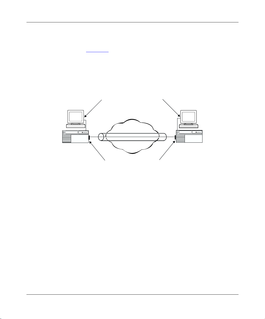
How GRE Tunneling Works
A simple point-to-point GRE tunnel terminates at router interfaces at each end of
the tunnel (Figure 1-1
more logical addresses. For IP and IPX protocols, at each tunnel end point there is
one logical address for each protocol configured for encapsulation over the tunnel.
Because the concept of an interface address does not exist in OSI, only one IP
address is required per router.
Configuring GRE Tunnels
). Each interface has a physical address and may have one or
Remote logical
host interface
Host
B
Router
2
Remote physical
router interface
IP0095A
Host
A
Router
1
Local physical
router interface
Local logical
host interface
GRE tunnel
Figure 1-1. Simple GRE Tunnel Components
The physical address, which is always an IP address, is visible to the devices
making up the intervening network cloud. The logical addresses are not visible to
the devices that make up the intervening network cloud. They are private
addresses, visible only to the networks on either side of the tunnel.
308625-14.20 Rev 00
1-3
Page 24

Configuring GRE, NAT, RIPSO, and BFE Services
The GRE tunnel can use any IP interface configured on the router as a physical
end point. To maximize the robustness of the tunnel, use a circuitless IP address as
a tunnel’s physical end point whenever possible. Because a circuitless IP address
is associated with the whole router, not one physical interface, the tunnel operates
as long as any slot that has a working IP interface stays up. (For instructions on
configuring a circuitless interface, see Configuring IP, ARP, RARP, RIP, and OSPF
Services.)
Example of Packet Handling in a GRE Tunnel
The following steps explain how GRE tunneling takes place. The example
describes a GRE tunnel encapsulating IP or IPX (refer to Figure 1-2
1.
The router interface on router 1 receives a packet from host 1, looks up the
packet’s destination address in its IP routing table, and determines that the
next hop to the destination address is the remote end of a GRE tunnel. The
router interface queues the packet at the tunnel interface for GRE
encapsulation.
2.
Router 1 adds a GRE header to the packet and sends the packet to IP.
3.
IP looks up the route to the remote tunnel end point and sends the
GRE-encapsulated packet to the appropriate next-hop address.
).
1-4
4.
The remote tunnel interface on router 2 removes the outer IP header and the
GRE header.
5.
The remote router interface looks up the packet’s destination address in its
routing table and chooses the next hop to reach host 2.
The same process would take place for IPX.
308625-14.20 Rev 00
Page 25

Configuring GRE Tunnels
Host
1
Key
interface
10.0.0.1
8.0.0.2
Data
Router 1
Router
Tunnel
interface
MAC header
Source IP address
Destination IP address
Transport protocol
Passenger protocol
Internet/Intranet
11.0.0.10
11.0.0.20
10.0.0.1
8.0.0.2
Data
MAC header
Source IP address
Destination IP address
GRE header
Source IP address
Destination address
Router 2
Tunnel
interface
MAC header
Source IP address
Destination IP address
Router
interface
10.0.0.1
8.0.0.2
Data
Host
2
Figure 1-2. GRE Tunnel Encapsulating the IP Protocol
GRE Packet Headers
The previous example followed the path of a GRE packet as it traversed the
tunnel, explaining its handling. Here is some detail about what occurs with the
headers of such a GRE packet. A GRE packet has the following headers
(Figure 1-3
308625-14.20 Rev 00
):
IP0064A
1-5
Page 26

Configuring GRE, NAT, RIPSO, and BFE Services
IP delivery header
GRE header
Payload packet
IP0110A
Figure 1-3. GRE Packet Headers
The outermost (delivery) header is an IP header with protocol type 0x47 (GRE).
For a packet arriving at the router through a tunnel, the destination address is an IP
interface that the network administrator configures as the GRE tunnel remote end
point. The next header is the GRE header (Figure 1-4
payload. The payload could be IP, IPX, or OSI, in which case it would contain an
identifying header of the protocol type.
). The last header is the
1-6
0123
01234567890123456789012345678901
Recur Flag Ver C
K S s
R
Key (optional)
Sequence number (optional)
Routing (optional)
Protocol type
Offset (optional)Checksum (optional)
IP0111A
Figure 1-4. Detail of GRE Header
For a more complete description of the GRE header, see RFC 1701.
308625-14.20 Rev 00
Page 27

Configuring GRE Tunnels
Requirements for GRE Tunnels Encapsulating IP Protocol
If you are using GRE tunneling to encapsulate the IPX or OSI protocol,
Note:
skip this section. The requirements discussed below do not apply to tunnels
encapsulating IPX or OSI.
Before configuring a tunnel encapsulating IP, you should be aware of a limitation
inherent in the use of all tunnels, including GRE tunnels. A tunnel is a virtual
point-to-point connection between two routers that are actually several hops apart.
This point-to-point connection can hide the real distance between the routers from
portions of the network, leading to unintended, suboptimal routing decisions and
in some cases, to routing loops.
In particular, if a router at one end of a tunnel determines that the best route to the
remote physical end point of the tunnel is through the tunnel itself, a loop, internal
to the router, occurs and prevents the tunnel from operating. You must configure
one of the following at each end of the tunnel to prevent routing loops:
• Announce policy
• Accept policy
• Static route
The best choice depends on the network topology to which it is applied.
When configuring a tunnel with IP encapsulation, you must implement
Note:
an announce or accept policy or a static route at each end of the tunnel for the
tunnel to operate correctly.
Announce Policies
An announce policy governs the advertisement of routing information. When
preparing a routing advertisement, IP consults its announce policies to determine
whether to advertise the route. For GRE tunneling, you can configure an announce
policy for each routing protocol (RIP, OSPF, BGP) configured on the logical
tunnel interface to block the advertisement of a range of network addresses that
contains the tunnel’s local physical interface address. For information about
configuring RIP and OSPF announce policies, see Configuring IP, ARP, RARP,
RIP, and OSPF Services. For information about configuring BGP announce
policies, see Configuring IP Exterior Gateway Protocols (BGP and EGP).
308625-14.20 Rev 00
1-7
Page 28

Configuring GRE, NAT, RIPSO, and BFE Services
The disadvantage of using an announce policy is that it prevents the advertisement
of other subnets within the blocked range. Depending on the network topology,
this configuration may not be desirable.
Accept Policies
An accept policy governs the addition of new routes to the routing tables. For
GRE tunneling, you can configure an accept policy for each routing protocol (RIP,
OSPF, BGP) configured on the logical tunnel interface to block the receipt of
advertisements from a range of network addresses that contains the tunnel’s
remote physical interface address. For information about configuring RIP and
OSPF accept policies, see Configuring IP, ARP, RARP, RIP, and OSPF Services.
For information about configuring BGP accept policies, see Configuring IP
Exterior Gateway Protocols (BGP and EGP).
The disadvantage of using an accept policy is that it prevents the receipt of
advertisements of subnets contained in the blocked range. Depending on the
network topology, this configuration may not be desirable.
Static Routes
1-8
A static route is a route configuration that designates a specific router within the
intervening network cloud as the next hop to the remote physical tunnel end point.
Because static routes take precedence over routes that the router learns
dynamically from routing protocols, this configuration forces the router to direct
packets through the cloud to reach the tunnel’s remote physical address.
The disadvantage of using a static route is that it is fixed. If the path through the
chosen next hop to the remote tunnel end point goes down, the tunnel goes down
as well until you manually reconfigure the static route. Similarly, even if the path
through the chosen next hop becomes more costly than the path through some
other attached router, the tunnel continues to use the more costly path unless you
manually intervene.
Note:
When configuring a static route, be careful not to inadvertently create a
loop.
308625-14.20 Rev 00
Page 29

Number of Tunnels Configurable per Router
The number of GRE tunnels you can configure on a router varies, depending on
the type of protocol being encapsulated.
For IP and IPX
You can create up to 64 GRE tunnels on one router; each GRE tunnel can have
multiple end points. You can configure up to 256 remote tunnel end points
distributed over the configured GRE tunnels for IP and IPX.
For OSI
GRE point-to-point and point-to-multipoint tunnels are viewed by OSI as
point-to-point subnetworks as defined by ISO 10589. Each GRE tunnel appears as
a single OSI interface. Configure GRE tunnels for OSI traffic within the following
guidelines:
• Each router interface can support one GRE tunnel configured with OSI.
• A single 32 Mb router slot can support a maximum of 48 interfaces.
Configuring GRE Tunnels
• The maximum number of end points per tunnel is 150.
Theoretically, a single slot could support 48 interfaces, each of which could be a
point-to-multipoint configuration. OSI would treat this configuration as 48 groups
of point-to-point subnetworks with each subnetwork having an adjacency. (An
adjacent router is the next hop on the path toward the destination.) Each adjacency
would have its own state machine, and flooding of data would be resource
intensive because datagrams would need to be propagated along each adjacency.
Such a configuration would have implications for buffer and memory usage.
308625-14.20 Rev 00
1-9
Page 30

Configuring GRE, NAT, RIPSO, and BFE Services
Creating a GRE Tunnel
To create a tunnel:
1. Configure the local tunnel end point.
Add one or more protocols (IP, IPX, or OSI) to the local tunnel end point.
2.
3. Configure the remote tunnel end point.
For instructions, see:
Topic Page
onfiguring the Local Tunnel End Point 1-10
C
Adding a Protocol to the Local Tunnel End Point 1-12
Configuring the Remote Tunnel End Point 1-16
Configuring the Local Tunnel End Point
When you create a GRE tunnel, you assign the tunnel a name and an IP address.
The IP address is the router interface used as the local physical end point for this
tunnel. The IP address must be that of an existing physical router IP interface or
the circuitless address. To maximize the robustness of the tunnel, use a circuitless
IP address as a tunnel’s physical end point whenever possible. (For instructions on
configuring a circuitless IP interface, see Configuring IP, ARP, RARP, RIP, and
OSPF Services.)
Using the BCC
1-10
This IP address is visible to the network cloud that the tunnel passes through.
To configure the local tunnel end point of a GRE tunnel:
1. Navigate to the box or stack prompt and enter:
tunnels
The tunnels prompt appears.
2. Navigate to the tunnels prompt (for example, box; tunnels) and enter the
following command:
gre name
<name>
local-address
<address>
308625-14.20 Rev 00
Page 31

Configuring GRE Tunnels
name
is a unique name for this tunnel.
Using Site Manager
To configure the local tunnel end point of a GRE tunnel, first configure IP on an
interface, and then complete the following tasks:
You do this System responds
1. In the Configuration Manager window,
2. Choose IP. The IP menu opens.
3. Choose GRE. The GRE Create Tunnels List window
4. Click on Add Tunnel. The Create GRE Tunnel window opens.
5. Set the following parameters:
6. Click on OK. You return to the GRE Create Tunnels
address
is a valid IP address of a local router interface expressed in
dotted-decimal notation.
For example, the following command sequence creates the tunnel boston with
the local physical end point 197.1.2.3 and verifies the addition:
tunnels#
gre/boston#
local-address 197.1.2.3
name boston
state enabled
choose Protocols.
•IP Interface
• Tunnel Name
Click on Help or see the parameter
descriptions beginning on page A-3.
gre name boston local-address 197.1.2.3
info
Site Manager Procedure
The Protocols menu opens.
opens.
List window.
308625-14.20 Rev 00
1-11
Page 32

Configuring GRE, NAT, RIPSO, and BFE Services
Adding a Protocol to the Local Tunnel End Point
The Nortel Networks implementation of GRE tunneling supports the
encapsulation of the IP, IPX, and OSI protocols over a GRE tunnel. When you add
a protocol to a tunnel, you are configuring its local logical interface. The local
logical interface is the address of the local host, the tunnel’s local logical end
point. This address is not visible to the network cloud that the tunnel passes
through.
You can configure OSPF on either a GRE tunnel’s physical interfaces
Note:
or its logical interfaces, but not on both. When configuring OSPF on a GRE
tunnel, disable MTU mismatch detection. If the MTU mismatch parameter is
enabled, an OSPF adjacency may fail to form over the tunnel.
Using the BCC
You can use the BCC to add an IP or an IPX protocol interface to a GRE tunnel.
Adding an IP Protocol Interface
To add an IP protocol interface to the local tunnel end point, navigate to the GRE
tunnel interface prompt (for example,
box; tunnels; gre/boston
) and enter:
1-12
ip address
address
is the valid IP address of the host interface at the local end of the tunnel
<address>
mask
<address>
expressed in dotted-decimal notation.
mask
is the mask associated with the IP address.
For example, the following command adds the IP interface 9.9.9.1/255.255.255.0
to the tunnel boston:
gre/boston#
ip/9.9.9.1/255.255.255.0#
ip address 9.9.9.1 mask 255.255.255.0
For a complete description of IP interface configuration, see Configuring IP, ARP,
RARP, RIP, and OSPF Services.
To configure an IPX protocol interface, go to the next section. Otherwise, go to
“Configuring the Remote Tunnel End Point” on page 1-16.
308625-14.20 Rev 00
Page 33

Configuring GRE Tunnels
Adding an IPX Protocol Interface
To add an IPX protocol interface to the local tunnel end point, navigate to the
GRE tunnel interface prompt (for example,
box; tunnels; gre/boston
) and enter:
ipx address
address
eight characters.
host_address
internetwork. Enter up to four characters in hexadecimal format. The IPX host
address maps to a physical data link layer address on a specific circuit or physical
interface.
For example, the following command adds the IPX interface 00112233 with the
host address 4411 to the tunnel boston:
gre/boston#
ipx/00112233#
For a complete description of IPX interface configuration, see Configuring IPX
Services.
Using Site Manager
The steps to add a protocol to the local tunnel end point vary, depending on which
protocol you are assigning.
Adding an IP or an IPX Protocol Interface
<address>
is a valid IPX network ID. Enter a four-byte hexadecimal string of up to
host-address
<host_address>
is a valid IPX host address that is unique within the IPX
ipx address 00112233 host-address 4411
To add an IP or an IPX protocol to the local tunnel end point, complete the
following tasks:
You do this System responds
1. In the Configuration Manager window,
2. Choose IP. The IP menu opens.
3. Choose GRE. The GRE Create Tunnels List window
308625-14.20 Rev 00
Site Manager Procedure
The Protocols menu opens.
choose Protocols.
opens.
(continued)
1-13
Page 34

Configuring GRE, NAT, RIPSO, and BFE Services
Site Manager Procedure
You do this System responds
4. Choose a tunnel from the list, and then
click on Add/Del Prot.
5. Choose one or more protocols from the
list, and then click on OK.
6. Enter the required information to configure
the IP or IPX interface, then click on OK.
For information about any parameter, click
on Help or see the appropriate protocol
guide.
7. Click on Done. You return to the Configuration Manager
(continued)
The Select Protocols window opens.
The appropriate protocol configuration
windows open.
You return to the GRE Create Tunnels
List window.
window.
Adding an OSI Protocol Interface
To add the OSI protocol to the local tunnel end point, complete the following
tasks. These instructions assume that one or more GRE tunnels have already been
configured.
Site Manager Procedure
1-14
You do this System responds
1. In the Configuration Manager window,
choose Protocols.
2. Choose IP. The IP menu opens.
3. Choose GRE. The GRE Create Tunnels List window
4. Choose a tunnel from the list, and then
click on Add/Del Prot.
5. Choose OSI from the list, and then click on
OK.
The Protocols menu opens.
opens.
The Select Protocols window opens.
The OSI Configuration window opens.
(continued)
308625-14.20 Rev 00
Page 35

Configuring GRE Tunnels
Site Manager Procedure
You do this System responds
6. Set the following parameters (required if
OSI has not been configured previously on
any other router interface):
• Router ID (hex)
• Area Address (hex)
For information about any parameter, click
on Help.
7. Click on OK. You are asked whether you want to edit
8. If you answer No, click on Done and skip
the rest of the steps in this table.
9. If you answer Ye s , you can change any of
the following parameters:
• Enable
• Routing Level
• L1 Default Metric
• L2 Default Metric
• L1 Designated Router Priority
• L2 Designated Router Priority
• IIH Hello Timer
• ISH Hello Timer
• ESH Configuration Timer
• Circuit Password
• IIH Hold Time Multiplier
• ISH Hold Time Multiplier
• Redirect Enable/Disable
For information about any parameter, click
on Help or consult the
Services
10. Click on OK. OSI appears next to the tunnel name in
11. Click on Done. You return to the Configuration Manager
guide.
Configuring OSI
(continued)
the OSI interface details (parameters).
OSI appears next to the tunnel name in
the GRE Create Tunnels List window, and
then you return to the Configuration
Manager window.
The Edit OSI Interface window opens.
the GRE Create Tunnels List window.
window.
308625-14.20 Rev 00
1-15
Page 36

Configuring GRE, NAT, RIPSO, and BFE Services
Configuring the Remote Tunnel End Point
A remote tunnel end point can be any IP interface configured on a Nortel
Networks router or another router that complies with RFCs 1701 and 1702. To
maximize the robustness of the tunnel, use a circuitless IP address as a tunnel’s
physical end point whenever possible. For instructions on configuring a circuitless
IP interface, see Configuring IP, ARP, RARP, RIP, and OSPF Services.
When you configure a remote tunnel end point, you assign it a name and specify
the IP address of the remote physical interface. The physical interface is the
physical router interface at the remote end of the tunnel. This address is visible to
the network cloud that the tunnel passes through.
The remote logical interface, required for an IP or an IPX interface, is not visible
to the network cloud.
For a remote tunnel end point of this protocol type
IP ✔✔
IPX ✔✔
OSI ✔
You must configure a remote...
physical interface logical interface
1-16
For a GRE tunnel configured with an IP, IPX, or OSI protocol, you can configure
one or more remote tunnel end points. For more information, see “
Number of
Tunnels Configurable per Router” on page 1-9.
308625-14.20 Rev 00
Page 37

Using the BCC
To configure a remote tunnel end point using the BCC, complete the following
steps.
Step 1. Configuring a Remote Physical Interface
To configure a remote tunnel end point, navigate to the GRE tunnel interface
prompt (for example,
box; tunnels; gre/boston
Configuring GRE Tunnels
) and enter:
remote-endpoint
name
is the unique name for the remote end of the tunnel.
address
is the valid IP address of the router interface at the remote end of the GRE
<name>
address
<address>
tunnel entered in dotted-decimal notation.
For example, the following command sequence configures the remote end point
austin with the physical interface 197.1.2.4 and verifies the entry:
gre/boston#
remote-endpoint/austin#
address 197.1.2.4
logical-ip-address 0.0.0.1
logical-ipx-address 000000000001
name austin
state enabled
Note:
remote-endpoint austin address 197.1.2.4
info
When you configure a remote physical end point, the BCC
automatically inserts a default address value for the remote logical interfaces.
For IP, the default address is 0.0.0.1; for IPX, it is 000000000001. These
addresses are not valid. Until you configure valid logical addresses, the tunnel
will not come up.
Step 2. Configuring a Remote Logical Interface
Using the BCC, you can configure a logical interface for a remote end point.
308625-14.20 Rev 00
1-17
Page 38

Configuring GRE, NAT, RIPSO, and BFE Services
Configuring a Remote Logical IP Interface
To configure a remote logical IP interface, navigate to the remote GRE tunnel
interface prompt (for example,
) and enter:
austin
box; tunnels; gre/boston; remote-endpoint/
logical-ip-address
address
is a valid IP address expressed in dotted-decimal notation.
<address>
For example, the following command sequence configures the remote logical IP
interface 9.9.9.2 for the remote tunnel end point austin and verifies the change:
remote-endpoint/austin#
remote-endpoint/austin#
name austin
address 197.1.2.4
logical-ip-address 9.9.9.2
logical-ipx-address 000000000001
state enabled
logical-ip-address 9.9.9.2
info
Configuring a Remote Logical IPX Interface
To configure a remote logical IPX interface, navigate to the remote GRE tunnel
interface prompt (for example,
) and enter:
austin
logical-ipx-address
address
is a valid IPX address up to 12 characters in length in hexadecimal
<address>
box; tunnels; gre/boston; remote-endpoint/
notation.
1-18
For example, the following command sequence configures the remote logical IPX
interface 00112255 for the remote tunnel end point austin and verifies the change:
remote-endpoint/austin#
remote-endpoint/austin#
name austin
address 197.1.2.4
logical-ip-address 9.9.9.2
logical-ipx-address 000000112255
state enabled
logical-ipx-address 00112255
info
308625-14.20 Rev 00
Page 39

Using Site Manager
Configuring a Remote End Point for IP or IPX
To configure a remote tunnel end point for either an IP or IPX protocol, complete
the following tasks:
You do this System responds
Configuring GRE Tunnels
Site Manager Procedure
1. In the Configuration Manager window,
choose Protocols.
2. Choose IP. The IP menu opens.
3. Choose GRE. The GRE Create Tunnels List window
4. Choose a tunnel from the list, and then
click on Remote Conn.
5. Click on Add. The Create GRE Remote Connection
6. Set the following parameters:
• Connection Name
• Remote Physical IP Address
• Remote Logical IP Address
• Remote Logical IPX Address (hex)
Click on Help or see the parameter
descriptions beginning on page A-5.
7. Click on OK. You return to the GRE Remote
8. Click on Done. You return to the GRE Create Tunnels
9. Click on Done. You return to the Configuration Manager
The Protocols menu opens.
opens.
The GRE Remote Connections List
window opens.
window opens.
Depending on which protocols you added
to the tunnel (IP, IPX, or both), Site
Manager allows you to configure the
Remote Logical IP Address or the
Remote Logical IPX Address (hex)
parameter, or both.
Connections List window.
List window.
window.
308625-14.20 Rev 00
1-19
Page 40

Configuring GRE, NAT, RIPSO, and BFE Services
Configuring a Remote End Point for OSI
To configure a remote tunnel end point for the OSI protocol, complete the
following tasks:
Site Manager Procedure
You do this System responds
1. In the Configuration Manager window,
choose Protocols.
2. Choose IP. The IP menu opens.
3. Choose GRE. The GRE Create Tunnels List window
4. Choose a tunnel from the list, and then
click on Remote Conn.
5. Click on Add. The Create GRE Remote Connection
6. Set the following parameters:
• Connection Name
• Remote Physical IP Address
Click on Help or see the parameter
descriptions beginning on page A-5.
7. Click on OK. The connection name appears in the
8. Click on Done. You return to the GRE Create Tunnels
9. Click on Done. You return to the Configuration Manager
The Protocols menu opens.
opens.
The GRE Remote Connections List
window opens.
window opens.
GRE Remote Connections List window.
List window.
window.
1-20
308625-14.20 Rev 00
Page 41

Customizing a GRE Tunnel
You can customize a configured GRE tunnel, as described in the following
sections:
Topic Page
Disabling and Reenabling a GRE Tunnel 1-21
Disabling and Reenabling a Protocol on a GRE Tunnel 1-22
Deleting a Protocol from a GRE Tunnel 1-24
Disabling and Reenabling a Remote Tunnel End Point 1-25
Deleting a Remote Tunnel End Point 1-26
Disabling and Reenabling a GRE Tunnel
When you create a GRE tunnel, the tunnel is enabled by default. You can use the
BCC or Site Manager to disable or reenable it.
Configuring GRE Tunnels
Using the BCC
To disable or reenable a GRE tunnel, navigate to the GRE tunnel interface prompt
(for example,
<state>
state
state
is one of the following:
enabled
disabled
box; tunnels; gre/boston
(default)
) and enter:
For example, the following command sequence disables the tunnel boston and
verifies the change:
gre/boston#
gre/boston#
local-address 197.1.2.3
name boston
state disabled
state disabled
info
308625-14.20 Rev 00
1-21
Page 42

Configuring GRE, NAT, RIPSO, and BFE Services
Using Site Manager
To disable or reenable a GRE tunnel, complete the following tasks:
Site Manager Procedure
You do this System responds
1. In the Configuration Manager window,
choose Protocols.
2. Choose IP. The IP menu opens.
3. Choose GRE. The GRE Create Tunnels List window
4. Select a tunnel from the list.
5. Set the Enable parameter. Click on Help
or see the parameter description on page
A-4.
6. Click on Apply. The selected tunnel is enabled or
7. Click on Done. You return to the Configuration Manager
The Protocols menu opens.
opens.
disabled.
window.
Disabling and Reenabling a Protocol on a GRE Tunnel
When you configure a protocol interface on a GRE tunnel, the interface is enabled
by default. You can use the BCC or Site Manager to disable or reenable it. If you
want to add an interface to the tunnel for either the IP or IPX protocol, see
“Adding a Protocol to the Local Tunnel End Point” on page 1-12.
Using the BCC
1-22
To disable or reenable either IP or the IPX protocol, navigate to the protocol
interface prompt (for example,
255.255.255.0
<state>
state
state
is one of the following:
enabled
disabled
) and enter:
(default)
box; tunnels; gre/boston; ip/9.9.9.1/
308625-14.20 Rev 00
Page 43

Configuring GRE Tunnels
For example, the following command disables the IP protocol interface
9.9.9.1/255.255.255.0:
ip/9.9.9.1/255.255.255.0#
Using Site Manager
To disable or reenable an IP, IPX, or OSI interface on a GRE tunnel, complete the
following tasks:
You do this System responds
1. In the Configuration Manager window,
2. Choose IP, IPX, or OSI. The IP, IPX, or OSI menu opens.
3. Choose Interfaces. The IP Interface List window, IPX
4. Select the interface that you want to
5. Set the Enable parameter.
6. Click on Done. You return to the Configuration Manager
Site Manager Procedure
choose Protocols.
enable or disable from the list.
state disabled
The Protocols menu opens.
Interfaces window, or the OSI Interface
Lists window opens, as appropriate.
Site Manager displays the parameter
values for that interface.
window.
308625-14.20 Rev 00
1-23
Page 44

Configuring GRE, NAT, RIPSO, and BFE Services
Deleting a Protocol from a GRE Tunnel
Use the BCC or Site Manager to delete a protocol from a GRE tunnel.
Using the BCC
To delete a protocol from a GRE tunnel, navigate to the protocol interface prompt
(for example,
delete
For example, the following command deletes the IP protocol interface
9.9.9.1/255.255.255.0 from the tunnel boston:
box; tunnels; gre/boston; ip/9.9.9.1/255.255.255.0
) and enter:
ip/9.9.9.1/255.255.255.0#
gre/boston#
Using Site Manager
To delete a protocol from a GRE tunnel, complete the following tasks:
You do this System responds
1. In the Configuration Manager window,
2. Choose IP. The IP menu opens.
3. Choose GRE. The GRE Create Tunnels List window
4. Select a tunnel from the list, and then click
5. Deselect the protocol.
6. Click on OK. You return to the GRE Create Tunnels
delete
Site Manager Procedure
The Protocols menu opens.
choose Protocols.
opens.
The Select Protocols window opens.
on Add/Del Prot.
List window.
1-24
308625-14.20 Rev 00
Page 45

Configuring GRE Tunnels
Disabling and Reenabling a Remote Tunnel End Point
When you configure a remote tunnel end point, it is enabled by default. You can
use the BCC or Site Manager to disable or reenable the remote tunnel end point.
If you want to add another remote tunnel end point for the tunnel, see
Note:
“Configuring the Remote Tunnel End Point” on page 1-16.
Using the BCC
To disable or reenable a remote tunnel end point, navigate to the remote GRE
tunnel interface prompt (for example,
remote-endpoint/austin
<state>
state
is one of the following:
state
) and enter:
box; tunnels; gre/boston;
enabled
disabled
(default)
For example, the following command sequence disables the remote tunnel end
point austin and verifies the change:
remote-endpoint/austin#
remote-endpoint/austin#
name austin
address 197.1.2.4
logical-ip-address 9.9.9.2
logical-ipx-address 00112255
state disabled
state disabled
info
308625-14.20 Rev 00
1-25
Page 46

Configuring GRE, NAT, RIPSO, and BFE Services
Using Site Manager
To disable or reenable a remote tunnel end point, complete the following tasks:
Site Manager Procedure
You do this System responds
1. In the Configuration Manager window,
choose Protocols.
2. Choose IP. The IP menu opens.
3. Choose GRE. The GRE Create Tunnels List window
4. Click on Remote Conn. The GRE Remote Connections List
5. Select the remote tunnel end point that
you want to disable or reenable from the
list.
6. Set the Enable parameter. Click on Help
or see the parameter description on page
A-4.
7. Click on Apply. The selected tunnel end point is enabled
Deleting a Remote Tunnel End Point
Use the BCC or Site Manager to delete a remote tunnel end point from a GRE
tunnel.
Using the BCC
The Protocols menu opens.
opens.
window opens.
or disabled.
1-26
To delete a remote tunnel end point, navigate to the remote GRE tunnel interface
prompt (for example,
box; tunnels; gre/boston; remote-endpoint/austin
) and
enter:
delete
For example, the following command deletes the remote tunnel end point austin:
remote-endpoint/austin#
gre/boston#
delete
308625-14.20 Rev 00
Page 47

Using Site Manager
To delete a remote tunnel end point, complete the following tasks:
You do this System responds
Configuring GRE Tunnels
Site Manager Procedure
1. In the Configuration Manager window,
choose Protocols.
2. Choose IP. The IP menu opens.
3. Choose GRE. The GRE Create Tunnels List window
4. Click on Remote Conn. The GRE Remote Connections List
5. Select the remote tunnel end point that
you want to delete, and then click on
Delete.
6. Click on OK. The remote tunnel end point is deleted.
Deleting a GRE Tunnel
Use the BCC or Site Manager to delete a GRE tunnel from the router.
Using the BCC
To delete a GRE tunnel, navigate to the GRE tunnel interface prompt (for
example,
delete
box; tunnels; gre/boston
The Protocols menu opens.
opens.
window opens.
A confirmation window opens.
) and enter:
For example, the following command deletes the tunnel boston:
gre/boston#
tunnels#
308625-14.20 Rev 00
delete
1-27
Page 48

Configuring GRE, NAT, RIPSO, and BFE Services
Using Site Manager
To delete a GRE tunnel, complete the following tasks:
Site Manager Procedure
You do this System responds
1. In the Configuration Manager window,
choose Protocols.
2. Choose IP. The IP menu opens.
3. Choose GRE. The GRE Create Tunnels List window
4. Select the tunnel that you want to delete
from the list, and then click on Del Tunnel.
5. Click on OK. You return to the GRE Create Tunnels
The Protocols menu opens.
opens.
A confirmation window opens.
List window.
1-28
308625-14.20 Rev 00
Page 49

Chapter 2
Configuring Network Address Translation
This chapter describes network address translation (NAT) and provides
instructions for configuring NAT on a router.
Topic Page
NAT Concepts
Examining How Different Types of NAT Work 2-13
NAT Implementation Guidelines 2-32
Starting NAT Services and Configuring Translations 2-40
Customizing NAT Global Parameters 2-65
Customizing a NAT Interface 2-74
Configuring NAT Static Address Translation 2-80
Configuring NAT Dynamic Address Translation 2-95
Configuring NAT N-to-1 Translation 2-113
2-2
308625-14.20 Rev 00
2-1
Page 50

Configuring GRE, NAT, RIPSO, and BFE Services
NAT Concepts
Network Address Translation is a method by which IP addresses are mapped from
one address realm to another, providing transparent routing to hosts (per RFC
2663). The NAT service implementation for BayRS allows network administrators
to configure a Nortel Networks router to be able to translate the source,
destination, or both the source and destination IP addresses of packets, for the
purpose of forwarding traffic between different networks with otherwise
incompatible addresses. For Transmission Control Protocol (TCP) and User
Datagram Protocol (UDP) traffic, NAT can also translate port numbers, allowing
multiple hosts to share a single address.
To understand how NAT works, think of the router configured with NAT (hereafter
referred to as “the NAT router”) as situated between two or more domains. In the
BayRS implementation of NAT, a domain is a network of devices with uniquely
assigned IP addresses, such that datagrams can be routed among them. The NAT
router borders the network domains where the IP addresses will be translated from
or to.
The public Internet can be considered an example of such a domain because any
device that connects to it must have a registered, unique address. Another example
of a domain would be an enterprise using a nonregistered block of addresses,
where care has been taken to avoid duplication of addresses within the enterprise
network. Because the enterprise uses nonregistered addresses, it would require a
NAT router to connect to the Internet.
2-2
You can configure the NAT router for address translations of IP traffic to occur
between two or more domains and for translations to be either unidirectional or
bidirectional. Both unidirectional and bidirectional NAT can be configured using
static and dynamic translation modes.
For more information, see the following topics:
Topic Page
Unidirectional NAT
Bidirectional (Multidomain) NAT 2-7
Translation Modes 2-10
308625-14.20 Rev 00
2-3
Page 51

Unidirectional NAT
For unidirectional NAT, the translation is done for addresses within the source
domain to route traffic to an address in a destination domain. When you are
configuring NAT, this source domain is given the special name of “private” and
the destination domain is given the special name “public.” The translation session
must be initiated from a device in the private domain.
The domain known to NAT services as “private” can include network addresses
that are unregistered or not globally unique. Such addresses are considered private
addresses. They are never advertised outside of their network domain. For
example, addresses 10.0.0.0 through 10.255.255.255 make up a range that is
reserved for use in private networks; it is not valid on the public Internet.
By contrast, the domain known to NAT services as “public” contains standard
registered IP addresses that are globally unique. These addresses are public
addresses. Public addresses are advertised both within and outside of the network
domain known as “public.”
Advantages
Configuring Network Address Translation
Unidirectional NAT offers a solution to two problems facing enterprises accessing
the Internet:
• The diminishing number of available IP addresses for Internet hosts
• Private networks with unregistered addresses that cannot access the Internet
Using NAT, you can create a pool of registered IP network addresses that the
router can dynamically map to the unregistered host addresses in your local
network. If an enterprise does not have enough globally unique IP addresses for
each host on its network, NAT can allow for the sharing of a limited number of
registered IP addresses by allocating them for use only as needed.
308625-14.20 Rev 00
2-3
Page 52

Configuring GRE, NAT, RIPSO, and BFE Services
Requirements
In addition to configuring NAT on the router, unidirectional NAT (including
unidirectional types SDPT and N-to-1) requires that you:
• Configure IP on each router interface to be configured with NAT.
• Configure Routing Information Protocol (RIP), RIP2, or static routes on the
NAT router interfaces. You must also configure RIP or static routes on each
device in the domain “private” that passes traffic into the NAT router for
address translation and on each device in the domain “public” that passes
traffic with translated addresses out of the NAT router.
For More Information About Unidirectional NAT
For an example of how unidirectional NAT works, see:
• “
Static Unidirectional Address Translation” on page 2-14
• “Dynamic Unidirectional Address Translation” on page 2-15
Before you configure unidirectional NAT for the first time, consult the section
“
NAT Implementation Guidelines” on page 2-32.
2-4
To configure unidirectional NAT, see:
Configuring Unidirectional NAT (Dynamic)” on page 2-40
• “
• “Adding a Static Unidirectional Address Mapping” on page 2-81
To view available NAT statistics during or after you configure bidirectional NAT,
consult the following:
For this information See
BCC show nat and show ip commands
NAT log messages “Logging NAT Messages” on page 2-69
Reference for BCC IP show Commands
308625-14.20 Rev 00
Page 53

Configuring Network Address Translation
Representing Multiple Hosts with a Single Address: SDPT and N-to-1
For TCP and UDP traffic, you can configure network address translation of many
private addresses to a single public address. Some applications that use TCP are
File Transfer Protocol (FTP), HyperText Transfer Protocol (HTTP), and Telnet.
Trivial File Transfer Protocol (TFTP) is an application that uses the UDP protocol.
For TCP and UDP traffic, there are two types of possible network address
translation types. Table 2-1 compares these unidirectional types, static destination
and port translation (SDPT) and N-to-1.
Table 2-1. Comparing NAT Types SDPT and N-to-1
SDPT (One to Many) N-to-1 (Many to One)
Definition
Packet type
Translation direction
Static vs. dynamic
configuration:
address and port
Aging
SDPT allows you to configure a single
public IP address to be translated to
many private addresses.
Valid for TCP or UDP packet forwarding
only
Supported for unidirectional NAT only;
the supported translation direction is
public to private
The user must statically configure both
address and port translation.
SDPT uses the translated port to
distinguish between application types
such as FTP and TFTP. The port is also
used to determine the destination host
on the private side of the NAT router.
SDPT mappings remain in the NAT
translation table until you disable or
delete them.
* Although SDPT can be initiated from the private as well the public side, Nortel
Networks recommends that you implement this type of configuration with a
simple static translation; it is not common that a network administrator would
need to translate a port from a host in a private domain to a destination in a
public domain.
*
N-to-1 allows you to configure a range
of addresses in a private network to be
translated into a single, public IP
address.
Valid for TCP or UDP packet forwarding
only
Supported for unidirectional NAT only;
translation direction is
The user must statically configure
address translation. Port numbers are
assigned dynamically when the NAT
router maps a private address to the
public address.
N-to-1 mappings are removed from the
NAT translation table after a specified
timeout period, unless the mapping
aging (timeout) parameter is disabled.
private to public
308625-14.20 Rev 00
2-5
Page 54

Configuring GRE, NAT, RIPSO, and BFE Services
The major difference between SDPT and N-to-1 translation is that N-to-1 applies
only for sessions initiated from the private domain, while SDPT allows sessions to
be initiated from the public domain. By configuring NAT N-to-1, an enterprise
using unregistered addressing on its internal network can use the NAT router to
translate those unregistered addresses into a single registered IP address, or
multiple IP addresses, for the purpose of making connections to the Internet.
SDPT typically provides support for a single application, such as HTTP or FTP,
because with NAT SDPT each private host is uniquely identified by a statically
defined port.
For More Information on SDPT and N-to-1
For an example of how the translation types SDPT and N-to-1 work, see:
• “
Static Destination and Port Translation (SDPT)” on page 2-20
• “Network Address Port Translation (N-to-1)” on page 2-23
Before you configure unidirectional SDPT or N-to-1 for the first time, consult the
section “
NAT Implementation Guidelines” on page 2-32.
To configure these translation types, see:
2-6
Adding an SDPT Address and Port Mapping” on page 2-89
• “
• “Configuring NAT N-to-1 Translation” on page 2-113
To view available NAT statistics during or after you configure SDPT or N-to-1,
consult the following:
For this information See
BCC show nat and show ip commands
NAT log messages “Logging NAT Messages” on page 2-69
Reference for BCC IP show Commands
308625-14.20 Rev 00
Page 55

Bidirectional (Multidomain) NAT
Bidirectional multidomain NAT is a unique feature of BayRS that enables:
• A single NAT router to support address translation among two or more
domains
• Sessions to be initiated from any one domain to any other domain
• Hosts in domains with overlapping address space to communicate with each
other, similar to what is known as “twice NAT” (for more information, see
RFC 2663).
Address translation between the source domain and the destination domain of the
NAT router can be initiated from any domain connected to the NAT router. In
bidirectional multidomain NAT, both the source address and destination address
are translated by the NAT router. For ease of reference in this guide, the term
bidirectional NAT is used interchangeably with, and has the same meaning as,
bidirectional multidomain NAT.
Advantages
Bidirectional NAT allows you to translate IP addresses on a NAT router connected
to two or more domains. As a network administrator, you might use a bidirectional
NAT configuration to allow:
Configuring Network Address Translation
• Users to initiate traffic from either side of a router configured with NAT
• Hosts in two domains with overlapping address space (with duplicate
• A NAT router to represent an address in one domain as a different address in
Requirements
In addition to configuring NAT on the router, bidirectional NAT requires that you:
• Configure IP on each router interface to be configured with NAT
• Configure RIP2 on the NAT router interfaces and on each router that will be
308625-14.20 Rev 00
addresses) to communicate with each other
another domain
exchanging routing updates in the domains of your bidirectional NAT
configuration. Otherwise, you must configure static routes or a combination
of RIP2 and static routes.
2-7
Page 56

Configuring GRE, NAT, RIPSO, and BFE Services
• Install Domain Name System (DNS) server on a machine with a public
interface to the NAT router. (DNS server software is available from third-party
suppliers.)
• Configure BayRS DNS proxy on each interface of a NAT router to be used for
dynamic bidirectional translation. Although you can also configure DNS
proxy for a static bidirectional network address translation, DNS proxy is not
required.
• Configure BayRS DNS client on each device in the domains of your
bidirectional NAT configuration that will be initiating translations on the NAT
router.
The domain names that you specify in your bidirectional NAT configuration can
be any name that is in accordance with RFC 1035. You cannot assign the special
names of “public” and “private” because these are reserved for use in configuring
unidirectional NAT.
How DNS Server, DNS Client, and DNS Proxy Work with Bidirectional NAT
BayRS DNS proxy server enables a Nortel Networks router to act as a DNS server.
Each instance of the DNS proxy server on the router contains a list of servers to
contact on behalf of the client.
2-8
Clients on a local area network (LAN) typically use DNS servers to obtain the IP
address of a host based on the host’s domain name. You must configure BayRS
DNS client software on each device that can initiate translations through the NAT
router in your bidirectional NAT configuration.
Each DNS request from any address domain used by NAT must come through the
NAT router. The DNS proxy server asks NAT for an address translation and
replaces the address information in the DNS packet with the translated addresses.
NAT puts these addresses in its translation table at the same time. When the client
host makes an IP request for the service it asked for in DNS, the client finds the
correct path to the destination because NAT already has the destination IP
addresses in its translation tables.
308625-14.20 Rev 00
Page 57

Configuring Network Address Translation
The DNS proxy server accepts DNS name service requests from hosts on either
side of the router configured for bidirectional NAT and forwards these requests to
a preconfigured external DNS server. When the DNS replies come back, the DNS
proxy server queries NAT services and determines whether the DNS returned
addresses need to be translated. NAT then supplies translated addresses to the
DNS proxy server, as appropriate.
For more information about DNS, see Configuring IP Utilities.
For More Information on Bidirectional NAT
For an example of how bidirectional NAT works, see:
• “
Static Bidirectional Address Translation” on page 2-26
• “Dynamic Bidirectional Address Translation with Two Domains” on page
2-28
• “Dynamic Bidirectional Address Translation with Three Domains” on page
2-29
Before you configure unidirectional NAT for the first time, consult the section
“
NAT Implementation Guidelines” on page 2-32.
To configure bidirectional NAT, see:
• “
• “Adding a Static Bidirectional Address Mapping” on page 2-84
To view available NAT statistics during or after you configure bidirectional NAT,
consult the following:
For this information See
BCC show nat and show ip commands
NAT log messages “Logging NAT Messages” on page 2-69
308625-14.20 Rev 00
Configuring Bidirectional NAT (Dynamic)” on page 2-50
Reference for BCC IP show Commands
2-9
Page 58

Configuring GRE, NAT, RIPSO, and BFE Services
Translation Modes
You can configure your router so that network address translation occurs in one or
more of the following translation modes:
• Static translations are the result of mappings of one address to another as
specified by the user. A static translation remains active until it is disabled or
deleted.
• Dynamic translations are triggered by host traffic whenever the NAT router
receives a packet whose source address falls within a specified filter range.
You configure possible address translations in advance of the translation
request. A dynamic address translation remains active until the specified
timeout.
Static Translation Mode
NAT static mode allows you to statically configure a translation address for a
private or unregistered address. The translated address will then be used to
represent the private host for any packets sent outside its private domain. Static
translations are for addresses from two domains.
2-10
Static address translation is possible on any NAT interface. You can statically
configure addresses for unidirectional NAT (including SDPT and N-to-1) and
bidirectional NAT. When configuring static NAT translations, two mapping entries
cannot share either the same original IP address or the same translated IP address.
Configuring NAT in static mode is especially useful for address translation among
a few hosts. Static address mappings can be used to preserve a translation entry or
to create a connection from a host on the public network to a host on the private
network, or vice versa.
For an example of how a static unidirectional translation works, see
“
Unidirectional NAT” on page 2-14. For instructions on how to configure static
translation, see “
Configuring NAT Static Address Translation” on page 2-80.
A static address translation mapping does not time out as dynamic translations do,
but remains active as long as the static mapping has not been disabled or deleted.
For instructions on how to disable or delete a static mapping, see:
Disabling and Reenabling a Static Address Mapping” on page 2-92
• “
• “Deleting a Static Address Mapping” on page 2-93
308625-14.20 Rev 00
Page 59

Configuring Network Address Translation
Dynamic Translation Mode
NAT dynamic translation mode allows you to configure a temporary mapping of
private domain addresses to an address pool of public addresses in the same
domain or in another domain. For dynamic NAT to function, you must configure a
source address filter and a translation pool.
• A source address filter is a range of addresses that you specify as requiring
dynamic translation by the NAT router. The source addresses are replaced by
NAT with ones from its associated translation pool. The source address filter
is similar to the term local address range used in NAT for BayRS versions
before Version 14.20.
For unidirectional NAT, the translation pool addresses associated with the
source address filter are located in the destination, outbound domain. For
bidirectional NAT, you can specify whether to use a translation pool defined
for the source, inbound domain or the destination, outbound domain.
• A translation pool is a range of IP addresses that you specify for the NAT
router to use when dynamically translating the source address, for
unidirectional NAT, or the source and destination addresses, for bidirectional
NAT for IP packets requiring address translation. The translation pool is
similar to the term global address range used in NAT for BayRS versions
before Version 14.20.
Address range considerations for dynamic translation mode
Using dynamic NAT, you can configure multiple source address filters and
translation pools for use within the same domain, provided the address ranges do
not overlap. That is, the address ranges specified for one source address filter must
not match another source address filter in the same domain, and the same is true of
addresses between translation pools within the same domain. Overlapping address
ranges are allowed between dynamic and static NAT configurations. For more
information on multiple source address filters within the same domain, see
“
Multiple Source Address Filters -- Order of Precedence for NAT Types” on page
2-35.
When configuring source address filters or translation pools for different domains,
you can use the same address range in one source address filter or translation pool
as you use for another source address filter or translation pool in a different
domain. For example, you can configure the address range 22.1.1.1/8 for a
translation pool in both domain1.net and domain2.net.
308625-14.20 Rev 00
2-11
Page 60

Configuring GRE, NAT, RIPSO, and BFE Services
Comparing unidirectional and bidirectional dynamic NAT
You can configure unidirectional or bidirectional NAT for dynamic translation.
For dynamic unidirectional NAT:
• When a router configured with NAT detects an outbound packet from an
address within a configured source address filter, NAT uses the translation
pool from which to map a public, registered address from a domain named
“public.” NAT replaces the packet’s original address with the public address,
and sends the outbound packet to its destination address in the domain named
“public.”
• When a router configured with NAT detects an inbound packet for a
destination address that falls within the configured translation pool, it replaces
the packet’s public destination address with the original address and sends the
packet to its destination on the domain named “private.”
For dynamic bidirectional NAT, when the NAT router detects an address that
matches a source address filter, the source and destination addresses are translated
into the next available address from a translation pool. You specify whether this
translation pool is in the same domain or in a different domain than the source
address filter.
2-12
For more information on dynamic translation mode
For examples of how dynamic network address translation works, see:
Dynamic Unidirectional Address Translation” on page 2-15
• “
• “Dynamic Bidirectional Address Translation with Two Domains” on page
2-28
• “Dynamic Bidirectional Address Translation with Three Domains” on page
2-29
For instructions on how to create and enable dynamic address translation,
including source address filters and translation pools, see “
Configuring NAT
Dynamic Address Translation” on page 2-95.
Dynamic NAT translations are active until the specified mapping timeout value is
reached. The translation remains in a translation table for as long as it is active. An
idle entry is removed after a specified timeout period. If the timeout parameter is
disabled, the mapping is not removed.
308625-14.20 Rev 00
Page 61

Configuring Network Address Translation
For instructions on how to configure mapping aging, see:
Enabling and Disabling the Dynamic Mapping Aging Timer” on page 2-71
• “
• “Configuring the Dynamic Mapping Timeout Value” on page 2-72
Examining How Different Types of NAT Work
The following sample translations illustrate the different ways in which you can
configure NAT for IP address and port translations:
For this type of unidirectional NAT Go to page
Static Unidirectional Address Translation
Dynamic Unidirectional Address Translation 2-15
Static Destination and Port Translation (SDPT) 2-20
Network Address Port Translation (N-to-1) 2-23
For this type of bidirectional NAT Go to page
Static Bidirectional Address Translation
Dynamic Bidirectional Address Translation with Two Domains 2-28
Dynamic Bidirectional Address Translation with Three Domains 2-29
2-14
2-26
To help illustrate how NAT works, the figures in this section contain address
information such as host, interface, source address filter, translation pool, and
translation table addresses. To view similar information about your actual NAT
configuration, use the BCC
show nat
scripts available through the Technician Interface. For more
show ip
or
show nat
commands. There are also
information, refer to “Checking Address Translations” on page B-10.
308625-14.20 Rev 00
2-13
Page 62

Configuring GRE, NAT, RIPSO, and BFE Services
Unidirectional NAT
You can configure the following types of unidirectional NAT: static unidirectional
NAT, dynamic unidirectional NAT, SDPT, and N-to1.
Static Unidirectional Address Translation
For a static, unidirectional network address translation, you must configure:
• A router with IP and NAT
• A private NAT router interface that belongs to the domain “private”
• A public NAT router interface that belongs to the domain “public”
• A static mapping pair of one host IP address (typically unregistered) in the
domain “private” to be translated into a registered IP address of a host in the
domain “public.” For example, you could statically map the private address
10.33.245.8 to the registered address 192.142.59.32 as shown in Figure 2-1
Then, based on this static mapping pair, the NAT router can use the registered,
public IP address 192.142.59.32 for the host 10.33.245.8 when the host needs to
make a connection to the Internet, say for a destination address of 66.123.5.74.
.
2-14
Domain named "private" Domain named "public"
Host A
10.33.245.8
Private
interface
Static mapping on NAT router
Source/inbound
domain
private
Original/private
address
10.33.245.8
NAT Router
Translated/public
address
192.142.59.32
Public
interface
Destination/outbound
domain
public
Figure 2-1. Static Unidirectional NAT Configuration
IP0121A
308625-14.20 Rev 00
Page 63

Configuring Network Address Translation
Dynamic Unidirectional Address Translation
NAT routers translate host addresses from inside private networks into registered
addresses that can be used in the public network. On its return trip, a packet using
a NAT-assigned registered address destined for the internal network is translated
back into its original private address. NAT maintains a table of current
translations. Translations remain in the table until they become inactive and time
out, freeing up the registered public address for use by other hosts.
In the example that follows, company A uses NAT to obtain public Internet access
for its hosts. Hosts on company A’s network need access to resources in
company B’s network. Company B is located in a different network on the
Internet. Its addresses are registered. NAT is configured on the router bordering
company A’s network and the public network. NAT enables communication
between the networks of company A and company B without requiring either
company to restructure its existing network.
The network administrator at company A configures NAT to detect the following
ranges of unregistered private addresses:
• 10.0.0.0 through 10.255.255.255
• 15.0.0.0 through 15.255.255.255
• 50.1.1.0 through 50.1.1.255
The network administrator also configures the following ranges of registered
public addresses:
• 192.55.10.0 through 192.55.10.255
• 192.20.10.0 through 192.20.10.255
In Figure 2-2
address 10.0.0.15 is sent to a destination address in company B’s network. The
destination is a publicly recognized registered address, 192.100.20.2. The packet
follows normal IP routing to the NAT border router at the egress point in
company A, the NAT router in Chicago.
308625-14.20 Rev 00
, a packet from company A’s network with unregistered source
2-15
Page 64

Configuring GRE, NAT, RIPSO, and BFE Services
Company A
Registered destination address
50.1.1.52
10.0.0.50
15.0.0.20
15.0.0.45
New York
Atlanta
10.0.0.1
Boston
Santa Clara
10.0.0.15
Chicago
(NAT router)
Unregistered source address
New York
Figure 2-2. Network Address Translation Example
Company B
192.100.20.2
London
Houston
IP0051A
2-16
308625-14.20 Rev 00
Page 65

Configuring Network Address Translation
When the router’s NAT interface receives a packet, the NAT router extracts the
source address, first checking whether the packet’s source address falls within a
configured source address filter. If it does, NAT compares the source address
against existing address translation entries in its translation table. In Figure 2-3
the NAT router detects a packet on a NAT interface that contains the
address 10.0.0.15.
,
NAT router
Source address
filter list
10.0.0.0 to 10.255.255.255
15.0.0.0 to 15.255.255.255
50.1.1.0 to 50.1.1.255
10.0.0.15 192.100.20.2
Source address Destination address
192.55.10.0 to 192.55.10.255
192.20.10.0 to 192.20.10.255
IP packet
Figure 2-3. NAT Detects the Source Address
If the host’s source address does not appear in the translation table and is within a
configured source address filter, the NAT router does the following:
Translation
pool list
10.0.0.2 192.55.10.2
Current private/public
mapping entry list:
10.0.0.1 192.55.10.1
IP0052A
1.
2.
3.
308625-14.20 Rev 00
Creates a new entry for the host
Dynamically assigns the next available, lowest registered IP address from a
translation pool
Changes the source address of the packet to the registered address
2-17
Page 66

Configuring GRE, NAT, RIPSO, and BFE Services
In Figure 2-4, the NAT router dynamically translates the source address,
10.0.0.15, to one of the available public addresses (in this case, 192.55.10.3) and
creates a new entry in the private/public translation entry list.
Current private/public
10.0.0.2 192.55.10.2
Source address
filter list
10.0.0.0 to 10.255.255.255
15.0.0.0 to 15.255.255.255
50.1.1.0 to 50.1.1.255
10.0.0.15
Source address Destination address
NAT router
Translation
pool list
192.55.10.0 to 192.55.10.255
192.20.10.0 to 192.20.10.255
IP packet
10.0.0.15 192.55.10.3
192.100.20.2
Figure 2-4. NAT Updates the Private/Public Translation Entry List
mapping entry list:
10.0.0.1 192.55.10.1
IP0053A
2-18
308625-14.20 Rev 00
Page 67

Configuring Network Address Translation
In Figure 2-5, the NAT router then replaces the private source address (10.0.0.15)
with the translated public address (192.55.10.3) and sends the packet on its way to
its destination in company B’s network.
Source address
filter list
10.0.0.0 to 10.255.255.255
15.0.0.0 to 15.255.255.255
50.1.1.0 to 50.1.1.255
192.55.10.3
Source address
NAT router
Translation
pool list
192.55.10.0 to 192.55.10.255
192.20.10.0 to 192.20.10.255
IP packet
10.0.0.15
10.0.0.2 192.55.10.2
10.0.0.15 192.55.10.3
192.100.20.2
Destination address
Current private/public
mapping entry list:
10.0.0.1 192.55.10.1
IP0054A
Figure 2-5. NAT Replaces the Private Address with a Registered Source Address
308625-14.20 Rev 00
2-19
Page 68

Configuring GRE, NAT, RIPSO, and BFE Services
The destination host uses the incoming packet’s source address to create a
destination address to send a packet back to the sending host. When the packet
arrives at company A’s NAT router:
1.
The NAT router checks the packet’s destination address. If it is a public
address from a configured translation pool, NAT compares the destination
address to entries in its translation table.
2.
If the NAT router finds the public IP address in the translation table, it
replaces the destination address with the original private address.
After a specified timeout period during which there have been no translated
packets for a particular address translation, company A’s NAT router removes the
mapping, freeing the public address for use by another inside host.
Static Destination and Port Translation (SDPT)
You can use static destination port translation to map a single public address to
many private addresses (one-to-many). SDPT is a unidirectional translation type
that translates from the domain named “public” to the domain named “private.”
NAT SDPT requires that you statically configure an original port and a translated
port. SDPT uses the translated port to distinguish between application types such
as FTP and TFTP.
2-20
Note:
SDPT translation is valid only for TCP or UDP packets. All non-TCP or
non-UDP packets with addresses that fall within the configured local address
range are dropped.
SDPT is intended primarily for situations where a server in the private domain
supports a particular application for users in the public domain. In this example,
the device at host A in a public domain network would like to initiate an HTTP
connection with an HTTP server in a private domain network. To initiate this
connection from a public network to a private network, you can configure a router
with NAT, such as the one shown in the center of Figure 2-6
.
308625-14.20 Rev 00
Page 69

Host A
55.0.0.1
Public
network
domain
Router
Configuring Network Address Translation
10.0.0.2
Private
network
domain
NAT
router
Port 8080
Router
HTTP
server
55.0.0.5
192.32.30.0
55.0.0.2
Host
192.32.28.0
10.0.0.1
Host
IP0113A
Figure 2-6. Sample Configuration for NAT SDPT
The HTTP server actually has a local IP address of 10.0.0.1 and a port number of
8080. However, in the translation table on the central NAT router, the HTTP server
is represented to the public network with a virtual public address of 192.32.29.17
and a virtual port number of 80. So, Host A sends a TCP packet using destination
address 192.32.29.17 and destination port 80.
When the packet arrives at the global IP interface of the NAT router, NAT picks up
the packet and recognizes that the destination address is an SDPT “public
address.” It looks in the NAT translation table to find the translation information.
NAT translates the destination address and destination port to the address and port
of the HTTP server (10.0.0.1 address and 8080 port) in the private network. Then
the packet is forwarded to the HTTP server.
The HTTP server sends a reply to host A with source address 10.0.0.1, source port
8080, and the destination address of host A (55.0.0.2). This packet is received by
the NAT private domain interface of the NAT router. NAT recognizes the source
address as an SDPT “private address” and translates the source address to the
virtual address 192.32.29.17 and the source port to the virtual port 80.
308625-14.20 Rev 00
2-21
Page 70

Configuring GRE, NAT, RIPSO, and BFE Services
It might seem as if this HTTP server has two identities: The server has its actual
identity on the private side (10.0.0.1 address and 8080 port) and the other is its
virtual identity (192.32.29.17 address and 80 port) on the public side. To initiate a
connection with the HTTP server, a host in the private domain uses the server’s
private (actual) identity and a host in the public domain uses the server’s public
(virtual) identity.
The host at 10.0.0.1 (seen in the public domain as having the address
192.32.29.17) could also be used as a TFTP server. For example, assume the
following configuration shown in Tab le 2- 2
Table 2-2. Sample Configuration for a Router Configured with NAT
for the NAT router in Figure 2-6.
NAT
Config.
1 SDPT 55.0.0.1 192.32.29.17 8080 80 TCP (HTTP)
2 SDPT 55.0.0.1 192.32.29.17 69 69 UDP (TFTP)
3 SDPT 55.0.0.2 192.32.29.17 23 2023 TCP (Telnet)
4 Static 55.0.0.1 192.32.29.17 0 0 0 (Any)
5 N-to-1 33.0.0.0/8 192.32.29.17 Any Dynamically
translationtype
private-address public-address private-port public-port protocol
TCP/UDP
assigned
The first row represents the configuration for the server to handle HTTP traffic;
the second row represents the configuration used for this server to act as a TFTP
server. Private-port is the port the server listens to in the private side of the
network; public-port is the port to which hosts in the public domain connect.
To act as a TFTP server, this same server listens for TFTP on private port 69. The
server needs to have a public-address identity that the user configures. The public
address is 192.32.29.17 and the port is 69. By convention, port number 69 is the
reserved port for TFTP. Any host in the public domain network that transfers files
using TFTP from this server sends UDP packets to IP address 192.32.29.17 and
port 69.
To use a different host but the same public address for Telnet services, you could
configure the router with the information in the third row of Tab le 2- 2
.
2-22
308625-14.20 Rev 00
Page 71

Configuring Network Address Translation
When TCP packets with a destination address of 192.32.29.17 arrive in the
NAT-configured public interfaces, the NAT router translates the destination port
and address to direct the packets to private address 10.0.0.2 and port 23. Note that
SDPT translations are exercised first. The static translation (configured in the
fourth row of Tab le 2- 2
) is used only when an SDPT translation is not found or
when the packet is neither TCP or UDP (remembering that SDPT works only with
these types of packets).
The N-to-1 translation configuration (configured in the fifth row of Tab le 2-2
)
uses the same global address (N-to-1 address) as the first SDPT translation.
Network Address Port Translation (N-to-1)
Using network address port translation (N-to-1), you can map many private
addresses to one public address (many-to-one). With N-to-1 translation, you
statically configure the address translation and NAT dynamically executes the port
translation. The original port is determined by the application running on the host
device that is sending packets to the NAT router. N-to-1 is a unidirectional NAT
type that translates addresses from the domain named “private” to a single address
in the domain named “public.”
Note:
N-to-1 translation is valid only for TCP or UDP packets. All non-TCP
or non-UDP packets with addresses that fall within the configured local
address range are dropped.
When NAT receives a packet on the private interface, the following events occur:
1. NAT determines that the private source address falls within the source address
filter configured for N-to-1 translation.
2. NAT assigns the packet a public source address based on the statically
configured N-to-1 address and dynamically assigns the next available unique
port number.
3. NAT transmits the packet on the public interface.
For example, in Figure 2-7
range of 10.0.0.0 through 10.255.255.255 in a source address filter and associated
this range of private addresses with public IP address 192.1.1.1.
308625-14.20 Rev 00
the network administrator has set up a private address
2-23
Page 72

Configuring GRE, NAT, RIPSO, and BFE Services
Host A Host B
Private source address: 10.0.0.1
Port: 2001
Host A Host B
Private source address: 10.0.0.2
Port: 2222
Interface to
domain named "private"
NAT
N-to-1
Public source address: 192.1.1.1
Port: 12000
NAT
N-to-1
Public source address: 192.1.1.1
Port: 54000
Interface to
domain named "public"
IP0075A
Figure 2-7. N-to-1 Translation (Part 1)
The following events occur:
1. NAT receives a packet from host A on the private interface with a source
address of 10.0.0.1 and a port number of 2001.
2-24
2. Determining that the private source address falls within the range configured
for N-to-1 translation, NAT stores the port number, replaces the private source
address with the public address 192.1.1.1, replaces the private port number
with the unique port number 12000, and transmits the packet on the public
interface.
3. Subsequently, NAT receives a packet from host B on the private interface with
private source address 10.0.0.2 and port number 2222. Determining that this
private source address falls in the same configured range, NAT replaces the
private source address with the public address 192.1.1.1, replaces the private
port number with the unique port number 54000, and transmits the packet on
the public interface.
When NAT receives a packet from a remote source on the public interface, the
following events occur:
1. NAT determines that the destination address on the packet is an N-to-1
address.
308625-14.20 Rev 00
Page 73

Configuring Network Address Translation
2. NAT uses the address and the port number to identify the destination host.
3. NAT replaces the destination IP address and TCP (or UDP) port number with
the original private address and port number and transmits it on the private
interface.
For example, in Figure 2-8
the following events occur:
1. NAT receives a packet on the public interface with the destination address
192.1.1.1 and port number 12000.
2. Determining that the destination address is an N-to-1 address, NAT uses the
address and the port number to locate the destination host, host A. NAT
replaces the public destination address and TCP (or UDP) port number with
the private address and port number and transmits the packet on the private
interface.
Host A Host B
NAT
N-to-1
Private destination address: 10.0.0.1
Port: 2001
Host A Host B
N-to-1
Private destination
address: 10.0.0.2
Port: 2222
Public destination address: 192.1.1.1
Port: 12000
NAT
Public destination
address: 192.1.1.1
Port: 54000
IP0076A
Figure 2-8. N-to-1 Translation (Part 2)
3. Subsequently, NAT receives a packet on the public interface with the
308625-14.20 Rev 00
destination address 192.1.1.1 and port number 54000. Determining that the
destination address is an N-to-1 address, NAT uses the address and the port
number to locate the destination host, host B. NAT replaces the public
destination address and TCP (or UDP) port number with the private address
and port number and transmits the packet on the private interface.
2-25
Page 74

Configuring GRE, NAT, RIPSO, and BFE Services
Bidirectional NAT
You can configure bidirectional NAT statically or dynamically, and with two or
more domains.
Static Bidirectional Address Translation
Choose static bidirectional NAT when you want to map just a few individual
addresses for NAT, with translations being initiated from different domains.
Packets sent to the NAT router from statically mapped hosts in either domain will
have their source and destination addresses translated by NAT.
For example, Figure 2-9
presents host A in domain 1 and host B in domain 2, with
a NAT router between these two domains. You could statically map host A’s
address 23.3.3.3 in domain 1 to the translation address 89.9.9.9, identifying the
domain name to which the NAT router will pass the IP packet.
domain1.net
Host A
23.3.3.3
Public
interface
Static mappings on NAT router
Source/inbound
domain
domain1.net
domain2.net
Original/private
address
23.3.3.3
46.6.6.6
NAT Router
Translated/public
address
89.9.9.9
57.7.7.7
domain2.net
Host B
46.6.6.6
Public
interface
Destination/outbound
domain
domain2.net
domain1.net
IP0120A
2-26
Figure 2-9. Static Bidirectional NAT Configuration
308625-14.20 Rev 00
Page 75

Configuring Network Address Translation
When host A transmits packets to the NAT router, NAT replaces the source
address in the IP packet with the translation address 89.9.9.9. Likewise, if host B
in domain 2 transmits packets into the NAT router, the outgoing IP packet would
bear the source address 57.7.7.7.
For bidirectional NAT, you must create a minimum of one such static mapping in
at least two domains so that host devices in either domain can initiate an address
translation by the NAT router. IP packets with translated source addresses can then
be passed out of the router to an alternate domain.
The configuration of DNS proxy, required for dynamic bidirectional NAT, is
optional for static bidirectional NAT. If you do not configure DNS proxy on the
NAT router, you must statically configure one mapping for each domain as
described above. However, if you do configure the NAT router as a DNS proxy
server, you must statically configure a minimum of two address mappings for each
domain, one for the inbound domain and one for the outbound domain. For more
information see “
Adding a Static Bidirectional Address Mapping” on page 2-84.
308625-14.20 Rev 00
2-27
Page 76

Configuring GRE, NAT, RIPSO, and BFE Services
Dynamic Bidirectional Address Translation with Two Domains
Figure 2-10
offers an example of bidirectional multidomain NAT with two
domains. DNS proxy is configured on the NAT router, a requirement for dynamic
bidirectional NAT. In this sample configuration, two private hosts (A and B) with
the same address can communicate with each other in either direction using the
public interfaces on either side of the NAT router configured with DNS proxy.
Host A Host B
8.1.1.1 8.1.1.1
Source Address Filter
(Domain 1)
8.0.0.0 -> 8.255.255.255
Domain 1
Public
interface
Router
interface
NAT router
and DNS proxy
DNS
server
Domain 2
Private
interface
Router
PublicPrivate
interface
Source Address Filter
(Domain 2)
8.0.0.0 -> 8.255.255.255
Translation Pool
(Domain 1)
192.1.0.0 -> 192.1.255.255
Translation Table
8.1.1.1 -> 192.5.0.1(inbound 1, outbound 2)
8.1.1.1 -> 192.1.0.1 (inbound 2, outbound 1)
192.5.0.1 (inbound 2) -> 8.1.1.1 (outbound 1)
192.1.0.1 (inbound 1) -> 8.1.1.1 (outbound 2)
Figure 2-10. Bidirectional NAT with DNS Proxy
2-28
Translation Pool
(Domain 2)
192.5.0.0 -> 192.5.255.255
IP0117A
308625-14.20 Rev 00
Page 77

Configuring Network Address Translation
A source address filter and translation pool are configured in each domain. Host A
in domain 1 generates a request to the DNS server to identify the address of host B
located in domain 2. Because the address of host B, located by the DNS server,
falls within the range of the source address filter configured for domain 2, the
NAT router translates this address and modifies the DNS reply to include the
translated address of host B.
Using the translation address in the destination address field of the IP header, host
A sends the packet to host B. The NAT router translates the destination address
back to its domain 2 representation. At the same time, the NAT router translates
the source address (host A’s private address) to a translation address to represent
host A in domain 2.
For instructions on how to configure a similar dynamic NAT configuration using
the BCC, see Appendix B, “Sample Bidirectional NAT Configuration.”
Dynamic Bidirectional Address Translation with Three Domains
Figure 2-11
shows an example of NAT in which the NAT router has configured
interfaces to three domains. This is a dynamic translation with DNS proxy
configured on the NAT router. In this example, a user at host A makes a
connection request, such as
ftp hostb.domain3
. Host A at domain 1 sends a DNS
request packet to the DNS server in its local domain. The local DNS server
forwards the request to the DNS proxy server on the NAT router, asking for the
address of host B in domain 3.
The DNS request packet is received by the NAT router DNS proxy. DNS proxy
formats a new DNS request packet with the source address equal to the IP address
of the interface (192.33.1.1) that the DNS request came in on, and the destination
address is set to the address of the DNS server (130.1.1.1) in the target host’s
domain.
The DNS server in the target host domain (3) receives the DNS request and sends
back a DNS response containing the address of host B (44.1.1.1), the target host,
to the DNS proxy. The DNS response packet is received by the NAT router DNS
proxy. DNS proxy asks for and receives from NAT a translation address
(128.1.0.2) for host B at domain 3 (44.1.1.1) contained in the DNS response.
DNS proxy modifies the DNS response message using the translation address
(128.1.0.2) it received from NAT. The modified DNS response message is
transmitted to the client host, host A (3.1.1.1) in the originating domain (1).
308625-14.20 Rev 00
2-29
Page 78

Configuring GRE, NAT, RIPSO, and BFE Services
Host A in domain 1 receives the DNS response message and saves the translation
IP address (128.1.0.2) of host B in domain 3. Host A in domain 1 starts to send
packets to host B in domain 3. The first packet is the FTP open packet. The
packets will have a source address of 3.1.1.1 (host A’s IP address) and a
destination address of 128.1.0.2 (host B’s translation address).
Host A
3.1.1.1
8.1.1.1
3.0.0.0
Domain 1 Domain 2
DNS Proxy at interface 192.33.1.1
NAT Router
DNS
server
3.1.1.1
3.0.0.0
Domain 3
Router 3
DNS
Server
130.1.1.1
Host B
44.1.1.1
9.1.1.1
Router 2 Router1
DNS
server
3.1.1.1
3.0.0.0
IP0118A
Figure 2-11. Bidirectional NAT with Three Domains
The NAT router receives packets on domain 1’s interface from host A destined for
host B. NAT replaces the translated destination address (128.1.0.2) with host B’s
domain specific address (44.1.1.1). NAT replaces host A’s domain-specific source
address (3.1.1.1) with the domain 3 translation address for host A (128.3.0.1).
2-30
308625-14.20 Rev 00
Page 79

Configuring Network Address Translation
Host B receives packets from and sends replies back to host A. The reply packets
will have a source address of 44.1.1.1 (host B’s IP address) and a destination
address of 128.3.0.1 (host A’s translation address). NAT receives packets on
domain 3’s interface. NAT replaces the translated destination address (128.3.0.1)
with host A’s domain-specific address (3.1.1.1).
Source Address Filter
(Domain 1)
3.0.0.0 -> 3.255.255.255 (outbound)
8.0.0.0.-> 8.255.255.255 (outbound)
Translation Pool
(Domain 1)
128.1.0.0 -> 128.1.255.255
44.1.1.1 (in3) (out1) (p1) -> 128.1.0.2 128.1.0.2 (in1) -> 44.1.1.1 (out3)
3.1.1.1 (in1) (out3) (p3) -> 128.3.0.1 128.3.0.1 (in3) -> 3.1.1.1 (out1)
3.1.1.1 (in1) (out2) (p2) -> 128.2.0.1 128.2.0.1 (in2) -> 3.1.1.1 (out2)
3.1.1.1 (in2) (out1) (p2) -> 128.1.0.1 128.1.0.1 (in1) -> 3.1.1.1 (out3)
3.1.1.1 (in3) (out2) (p2) -> 128.3.0.1 128.3.0.1 (in2) -> 3.1.1.1 (out3)
9.1.1.1 (in2) (out1) (p2) -> 128.2.0.2 128.2.0.2 (in1) -> 9.1.1.1 (in2)
Source Address Filter
(Domain 2)
3.0.0.0 -> 3.255.255.255 (outbound)
9.0.0.0.-> 9.255.255.255 (inbound)
Translation Pool
(Domain 2)
128.2.0.0 -> 128.2.255.255
Multidomain Translation Table
Source Address Filter
(Domain 3)
3.0.0.0 -> 3.255.255.255 (inbound)
44.0.0.0.-> 44.255.255.255 (outbound)
Translation Pool
(Domain 3)
128.3.0.0-> 128.3.255.255
Figure 2-12. Network Address Translations Associated with Figure 2-11
NAT also replaces host B’s domain-specific source address (44.1.1.1) with
host B’s domain 1 translation address (128.1.0.2). Note that host B’s domain 1
translation address is defined here as the address for packets originating from
host B when they are sent to domain 1. A different translation address may be
used for host B when host B sends packets to other domains.
IP0118B
Host A receives packets from host B. The process is repeated until the FTP
session is done.
308625-14.20 Rev 00
2-31
Page 80

Configuring GRE, NAT, RIPSO, and BFE Services
NAT Implementation Guidelines
Before you implement a NAT configuration, you should be aware of the following
information.
Topic Page
eneral Configuration Considerations 2-32
NAT G
Protocol Requirements and Compatibilities 2-33
Multiple Source Address Filters -- Order of Precedence for NAT Types 2-35
Internet Control Message Protocol and Message Handling 2-39
NAT General Configuration Considerations
For NAT to function, at a minimum you must configure a NAT interface to a
device in each domain. You can configure multiple NAT router interfaces to a
single domain to be used in your NAT configuration.
• For unidirectional NAT, you must configure at least one router interface to be
in the private domain and one interface to be in the public domain. These
interfaces, are known as the private interface (has private address) and the
public interface (has public address), respectively.
2-32
• For bidirectional multidomain NAT, you must configure NAT on a router
interface to each domain that will be used for network address translation. The
interface between the NAT router and each respective domain in a
bidirectional configuration must be a public IP address.
You must configure as a NAT interface any network interface that is used to
forward packets that have been translated by NAT. Otherwise, packets may be
dropped.
The network address translations occurring in one domain must be independent of
the translations occurring in the opposite direction. For this reason, each NAT
interface must be assigned to only one domain. However, a domain can have more
than one NAT interface configured for it.
Note:
NAT does not support address translations for addresses that exist
within a packet payload, with the exception of DNS requests (bidirectional
NAT) and the FTP
command (unidirectional NAT).
port
308625-14.20 Rev 00
Page 81

Configuring Network Address Translation
Protocol Requirements and Compatibilities
Consider the following guidelines related to protocol requirements and
compatibilities when configuring NAT.
NAT Requires IP Forwarding
IP must be configured on the router that you will configure as the NAT router. For
IP forwarding, a unidirectional NAT configuration (including NAT types SDPT
and N-to-1) requires that you configure either the RIP1 or RIP2 routing protocol
or static routes, or a combination of these.
Bidirectional NAT requires that either RIP2 be configured on each interface in
your NAT configuration that will be used for bidirectional NAT, or that you
configure static routes between devices in your configuration.
OSPF and BGP Supported for Unidirectional NAT Only
In your unidirectional NAT configuration, if the NAT router will translate
addresses for OSPF traffic, you must set the value of the Site Manager AS
Boundary Router parameter to Yes (or in the BCC, set the value of
as-boundary-router to true).
The AS boundary router parameter indicates whether or not the router functions as
an AS boundary router. Only AS boundary routers can convert non-OSPF routes
into OSPF routes so that they can be passed along throughout the OSPF routing
domain. The router can be an AS boundary router if one or more of its interfaces
is connected to a non-OSPF network (for example, RIP, BGP, or EGP).
Bidirectional NAT does not support the IP routing protocols OSPF or BGP.
ISP Mode Not Supported by NAT
NAT does not support the ISP mode feature. ISP mode is a BayRS global IP
parameter that allows you to enable the BGP soloist and disable IP forwarding
caches. By default, ISP mode is disabled in BayRS.
ECMP Mode Supported for Unidirectional NAT Only
Unidirectional NAT supports Equal Cost Multi-Path (ECMP) mode. ECMP is a
load-balancing feature that allows IP to distribute traffic over up to five equal-cost
paths to the same destination. By default, ECMP support is disabled in BayRS.
308625-14.20 Rev 00
2-33
Page 82

Configuring GRE, NAT, RIPSO, and BFE Services
Compatibility of NAT and IPsec on a Router Interface
You can configure both unidirectional NAT and Internet Protocol Security (IPsec)
on the same router interface. However, the address ranges you configure for NAT
and those you configure in IPsec policy filters cannot overlap (be the same).
You can configure both IPsec and NAT using either the BCC or Site Manager.
When you configure NAT and IPsec on the same router interface, NAT and IPsec
operate independently and do not pass traffic to each other.
With both protocols configured on the same router interface, NAT takes
precedence over IPsec. For example, if the destination address of an incoming IP
packet does not match any configured NAT public address, then the packet is
processed by IPsec. If the IP packet contains an address that falls within the
configured range of an IPsec policy, then the packet is either protected, bypassed,
or dropped. A packet with a source address not within any IPsec policy range will
be dropped.
Router interfaces configured for bidirectional NAT do not support IPsec.
Special Considerations for Configuring NAT SDPT for FTP
FTP is an application-level protocol that supports the exchange of files between
two hosts. FTP requires clients to satisfy security authorization in the form of a
login and password. FTP is supported by all NAT types.
However, NAT SDPT support requires that you configure two SDPT translations.
One of these translations is for the control connection and one is for the data
connection.
NAT
Config. translation-type private-address public-address private-port public-port protocol
1 SDPT 55.0.0.1 192.32.29.17 21 21 TCP
2 SDPT 55.0.0.1 192.32.29.17 20 20 TCP
Special Considerations for Configuring NAT SDPT for TFTP
TFTP is an application-level protocol that is a simplified version of FTP. Like
FTP, TFTP transfers data files, but unlike FTP, it does not provide password
protection. Also, TFTP runs on top of the connectionless datagram delivery
service, UDP. TFTP is supported by all NAT types.
2-34
308625-14.20 Rev 00
Page 83

Configuring Network Address Translation
However, NAT SDPT support requires that you combine several translation types
in your configuration. Two possible configuration scenarios are as follows:
• Configure SDPT translation “inside” an N-to-1 range, and set the N-to-1
address to be identical to the SDPT translated address.
translation-type private-address public-address private-port public-port protocol
N-to-1 55.0.0.0/255 192.32.29.17 Not applicable Not applicable Not applicable
SDPT 55.0.0.1 192.32.29.17 69 69 UDP
• Configure a static translation with the same original address and translated
address as the SDPT translation.
translation-type private-address public-address private-port public-port protocol
SDPT 55.0.0.1 192.32.29.17 69 69 UDP
Static 55.0.0.1 192.32.29.17 Not applicable Not applicable Not applicable
Multiple Source Address Filters -- Order of Precedence for NAT Types
You can configure NAT so that a source address in a domain falls within two or
more source address filters. When a domain has more than one configured source
address filter, the most specific matching translation determines which type of
NAT is used.
The order of translation precedence for routers configured with NAT is generally
as follows:
1.
2.
3.
4.
308625-14.20 Rev 00
SDPT
Static address translation
N-to-1 dynamic port translation
Dynamic address translation
2-35
Page 84

Configuring GRE, NAT, RIPSO, and BFE Services
When N-to-1 dynamic port translation is enabled, the source address (private
interface) or the destination address (public interface) is looked up in the
translation table to determine which type of translation applies to this packet. For
example, for the ranges illustrated in Figure 2-13
:
If a packet arrives at the interface in the
private domain with a source address of:
55.1.1.1 Dynamic
55.0.1.1 N-to-1 dynamic
55.0.0.0
55.1.0.0
N-to-1 dynamic
range
Dynamic
range
55.1.255.255
This type of address translation
occurs:
2-36
55.255.255.255
IP0114A
Figure 2-13. Sample Translation Types and Address Ranges
308625-14.20 Rev 00
Page 85

Configuring Network Address Translation
Figure 2-14 illustrates a NAT configuration in which a dynamic address range
encloses an N-to-1 dynamic range, which encloses a static translation range. The
static translation is the most specific. For the ranges illustrated in Figure 2-13
:
If a packet arrives at the interface in the
private domain with a source address of:
This type of address translation
occurs:
55.1.2.3 Static
55.1.2.2 N-to-1 dynamic
55.55.1.1 Dynamic
55.0.0.0
55.1.0.0
55.1.2.3
Dynamic
range
N-to-1 dynamic
range
Static
range
55.1.2.3
55.1.255.255
Figure 2-14. More Sample Translation Types and Address Ranges
308625-14.20 Rev 00
55.255.255.255
IP0115A
2-37
Page 86

Configuring GRE, NAT, RIPSO, and BFE Services
Figure 2-15 illustrates configured NAT ranges that do not overlap. Packets with a
source address that falls within any of these ranges will be translated with the
translation type associated with each range. Packets falling outside these ranges
are not delivered to NAT and are processed as normal IP packets.
10.1.0.0
Dynamic
range
10.1.255.255
10.5.0.0
Dynamic
range
10.5.255.255
10.10.10.0
N-to-1 dynamic
range
2-38
10.10.10.255
192.32.29.192
Static
range
192.32.29.192
IP0116A
Figure 2-15. Non-overlapping Address Ranges
308625-14.20 Rev 00
Page 87

Configuring Network Address Translation
Internet Control Message Protocol and Message Handling
NAT automatically allows Internet Control Message Protocol (ICMP)
communication and message handling. However, for N-to-1 network address
translation, ICMP is supported only under the following conditions:
• When initiated from the private side of the network, N-to-1 network address
translation processes ICMP communication between the following pairs. If
any of these requests are received on a unidirectional outbound NAT interface,
the NAT router logs an event message and does not process the packet.
-- ICMP echo request and ICMP echo response
-- ICMP timestamp request and ICMP timestamp response
-- ICMP echo mask request and ICMP echo mask response
• When initiated from either the private or public side of the network, N-to-1
translation supports the following ICMP error messages. If the “ICMP
redirect error” message occurs, the NAT router logs an event message and
does not process the packet.
-- ICMP destination unreachable
308625-14.20 Rev 00
-- ICMP time exceeded
-- ICMP parameter problem
-- ICMP source quench
2-39
Page 88

Configuring GRE, NAT, RIPSO, and BFE Services
Starting NAT Services and Configuring Translations
This section provides instruction in how to start NAT and how to configure
dynamic NAT, whether configuring unidirectional or bidirectional translations.
• For instructions on how to configure unidirectional NAT, see page 2-40
• For instructions on how to configure bidirectional NAT, see page 2-50
You can use the BCC or Site Manager to start NAT on the router. For instructions
on how to start and use the BCC or Site Manager, see Using the Bay Command
Console (BCC) or Configuring and Managing Routers with Site Manager.
Configuring Unidirectional NAT (Dynamic)
The following procedures explain how to start NAT services and configure
unidirectional NAT, using either the BCC or Site Manager.
If you want to configure using Go to the instructions on page
The BCC 2-40
Site Manager 2-45
Using the BCC
To use the BCC to configure a dynamic unidirectional network address translation
on a router using default values for most parameters:
.
.
2-40
1.
Add NAT to a router interface.
2.
Specify the domain named “private.”
3.
Specify a source address filter for the private domain.
4.
Specify the domain named “public.”
5.
Specify a translation pool.
6.
Configure the private NAT interface.
7.
Configure the public NAT interface.
These steps are described in the following sections.
308625-14.20 Rev 00
Page 89

Configuring Network Address Translation
Step 1. Add NAT to a router interface
To configure NAT on a router interface, navigate to an IP interface and add NAT
(for example,
nat
box; ethernet 2/1; ip
<ip_address>
) and enter:
When you first add NAT to a router interface, NAT is globally available on the
router.
Step 2. Specify the domain named “private”
To specify the domain named “private” in NAT using the BCC, navigate to the
NAT prompt (for example,
domain private
box; ip; nat
) enter:
When configuring unidirectional NAT, you must use the special domain name
“private” to identify the domain that you want NAT to translate addresses from.
Step 3. Specify a source address filter for the private domain
For unidirectional NAT, the source address filter specifies to the router which
source addresses from a single domain NAT should translate into public
addresses. For dynamic NAT to work, you must configure at least one source
address filter. For unidirectional NAT, the source address filter contains a range of
private host addresses that NAT uses to translate into public addresses configured
in a translation pool. In unidirectional NAT, you must use the special domain
name “private” to configure a source address filter.
You specify a source address filter as a start address and a prefix length
(from 1 through 32 decimal). The prefix length determines the number of
available addresses in the source domain. For example, if the start address is
10.1.10.0 and its prefix length is 24 (255.255.255.0), then the source address filter
range you specify includes addresses 10.1.10.0 to 10.1.10.255.
To configure a source address filter, navigate to the domain name prompt
(for example,
src-filter
start_address
Use dotted-decimal notation.
308625-14.20 Rev 00
box; ip; nat; domain private
<start_address>/<prefix_length>
) and enter:
specifies the start of the IP address range available for translation.
2-41
Page 90

Configuring GRE, NAT, RIPSO, and BFE Services
prefix_length
specifies the end of the IP address range available for translation.
Use an integer from 1 through 32 that represents the number of contiguous bits in
the network portion.
Example
This example shows the creation of a domain named “private” followed by the
specification of a source address filter with an address range from 10.0.0.0 to
10.255.255.255. (Note that addresses 10.0.0.0 through 10.255.255.255 or address
10.0.0.0 with a prefix length of 8 is a range that is reserved for use in private
networks; it is not valid on the public Internet.)
nat#
domain private
domain/private#
src-filter/10.0.0.0/8/private#
n-to-1 0.0.0.0
next-hop-address 0.0.0.0
prefix-length 8
start-address 10.0.0.0
state enabled
type 1-to-1
unnumbered-circuit-name {}
use-translation-pool outbound
src-filter/10.0.0.0/8/private#
The
command lets you see the values configured so far for this source address
info
src-filter 10.0.0.0/8
info
filter. Because only the start-address and prefix-length parameters have been
configured, the rest of the values displayed by the
command are default
info
values. The values 0.0.0.0 and {} mean that these parameters have not been set, so
they are inactive. The type parameter is a read-only parameter that indicates
whether the type of NAT being configured is static or dynamic (1-to-1) or N-to-1
(n-to-1).
2-42
The use-translation-pool parameter specifies whether the translation pool is
defined for the inbound (source) or outbound (destination) domain. For
unidirectional NAT, the value for use-translation-pool must be
bidirectional NAT, the value can be either
inbound
outbound
or
outbound
. For
(the default).
Step 4. Specify the domain named “public”
To specify the domain named “public” in NAT using the BCC, navigate to the
NAT prompt (for example,
domain public
box; ip; nat
) enter:
308625-14.20 Rev 00
Page 91

Configuring Network Address Translation
When configuring unidirectional NAT, you must use the special domain name
“public” to identify the domain that you want NAT to translate addresses to.
Step 5. Specify a translation pool for the public domain
For unidirectional NAT, a translation pool is a range of IP addresses that you
configure for NAT to use when dynamically translating the source addresses from
IP packets matching a configured source address filter. For dynamic network
address translation to work, you must configure at least one translation pool.
You specify a translation pool as a start address and a prefix length (from
1 through 32 decimal). The prefix length determines the number of available
public addresses. For example, if the start address is 197.1.2.0 and its prefix length
is 24 (255.255.255.0), then the translation pool range you specify includes
addresses 197.1.2.0 through 197.1.2.255.
When configuring unidirectional NAT, you must use the special domain name
“public” to identify the domain for the translation pool.
To configure a translation pool, navigate to the domain name prompt for public
(for example,
box; ip; nat; domain public
) and enter:
trans-pool
start_address
Use dotted-decimal notation.
prefix_length
Use an integer from 1 to 32 that represents the number of contiguous bits in the
network portion.
Example
This example shows the creation of a domain named “public” followed by the
specification of a translation pool with an address range from 199.1.42.0 to
199.1.42.255.
nat#
domain/public#
trans-pool/199.1.42.0/24/public#
trans-pool/199.1.42.0/24/public#
308625-14.20 Rev 00
<start_address>/<prefix_length>
specifies the start of the IP address range available for translation.
specifies the end of the IP address range available for translation.
domain public
trans-pool 199.1.42.0/24
info
prefix-length 24
start-address 199.1.42.0
state enabled
2-43
Page 92

Configuring GRE, NAT, RIPSO, and BFE Services
The
command lets you see the values configured so far for this source address
info
filter. By default, the state of the translation pool is enabled.
Step 6. Configure the NAT private interface
For unidirectional NAT, the private interface is the NAT router interface
connected to a device in the domain specified for the source address filter. The
router performs address translation only on packets from hosts included in the
source address filter. Remember that when you are configuring unidirectional
NAT, you must use the special domain names “private” and “public” to identify
the domains that NAT translates addresses from or to.
To specify the private NAT interface between the router and the domain named
“private,” navigate to the appropriate IP interface prompt (for example,
ethernet/2/2; ip/192.132.45.3/255.255.255.0
nat private
) and enter:
box;
Step 7. Configure the NAT public interface
For unidirectional NAT, the public interface is the NAT router interface connected
to a device in the domain specified for the translation pool. Remember that when
you are configuring unidirectional NAT, you must use the special domain names
“private” and “public” to identify the domains that NAT translates addresses from
or to.
2-44
IP packets arriving at the public interface from the public network are looked up
and, if the source address is within the range of the source address filter, the
address is translated by NAT.
To specify the public NAT interface between the router and the domain named
“public,” navigate to the appropriate IP interface prompt (for example,
ethernet/2/1; ip/192.132.22.10/255.255.255.0
nat public
) and enter:
308625-14.20 Rev 00
box;
Page 93

Configuring Network Address Translation
Using Site Manager
Before you can start NAT on the router, you must configure a circuit that the
protocol can use as an interface to an attached network. For instructions, see
Configuring Ethernet, FDDI, and Token Ring Services or Configuring WAN Line
Services.
To use Site Manager to configure a dynamic unidirectional network address
translation on a router using default values for most parameters:
1.
Configure NAT on the router and specify the private NAT interface.
2.
Configure NAT on the public interface.
3.
Configure a source address filter.
4.
Configure a translation pool.
These steps are described in the following sections.
Step 1. Configure NAT on the router and specify the NAT private
interface
When you first configure NAT on a router interface, NAT is available globally on
the router.
For unidirectional NAT, the private interface is the NAT router interface
connected to a device in the domain specified for the source address filter. When
configuring unidirectional NAT, you must use the special domain name “private”
to identify the domain that you want NAT to translate addresses from. The router
performs address translation only on packets from hosts included in the source
address filter.
After you have already configured IP on the router, follow these steps to configure
NAT on the router and specify the private NAT interface:
You do this System responds
1. In the Configuration Manager window,
308625-14.20 Rev 00
Site Manager Procedure
The Edit Connector window opens.
click on the connector that you want to
configure as the NAT private interface.
(continued)
2-45
Page 94

Configuring GRE, NAT, RIPSO, and BFE Services
Site Manager Procedure
You do this System responds
2. Click on Edit Circuit. The Circuit Definition window opens.
3. Choose Protocols. The Protocols menu opens.
4. Choose Add/Delete. The Select Protocols window opens, with
5. Click on NAT. A check mark appears next to NAT.
6. Click on OK. The NAT Global Configuration window
7. Click on OK to accept the default values
for NAT global parameters.
8. Click on OK to accept the special domain
name “private.”
9. Choose File. The File menu opens.
10. Choose Exit. You return to the Configuration Manager
(continued)
a check mark next to IP.
opens.
The NAT Interface Configuration window
opens.
The Circuit Definition window displays the
circuit configured with NAT.
window.
Step 2. Configure the NAT public interface
For unidirectional NAT, the public interface is the NAT router interface connected
to a device in the domain specified for the translation pool. When configuring
unidirectional NAT, you must use the special domain name “public” to identify the
domain that you want NAT to translate addresses to.
2-46
IP packets arriving at the public interface from the domain public are looked up
and, if their source address matches one in the source address filter, the address is
translated by NAT.
To configure the public NAT interface, complete the following tasks:
Site Manager Procedure
You do this System responds
1. In the Configuration Manager window,
click on the connector that you want to
configure as the NAT public interface.
2. Click on Edit Circuit. The Circuit Definition window opens.
The Edit Connector window opens.
(continued)
308625-14.20 Rev 00
Page 95

Configuring Network Address Translation
Site Manager Procedure
You do this System responds
3. Choose Protocols. The Protocols menu opens.
4. Choose Add/Delete. The Select Protocols window opens.
5. Click on NAT, and then click on OK. The NAT Interface Configuration window
6. Enter public in the Domain Name
parameter to specify the special domain
name “public,” and then click on OK.
7. Choose File. The File menu opens.
8. Choose Exit. You return to the Configuration Manager
(continued)
opens.
You return to the Circuit Definition
window.
window.
Step 3. Configuring a source address filter
For unidirectional NAT, the source address filter specifies to the router which
source addresses from a single domain NAT translates into public addresses. For
dynamic NAT to work, you must configure at least one source address filter.
You specify a source address filter as a starting IP address and a prefix length
(from 1 through 32 decimal). The prefix length determines the number of
available addresses. For example, if the base address is 197.1.2.0 and its prefix
length is 24 (255.255.255.0), then the address range you specify includes
addresses 197.1.2.0 through 197.1.2.255.
To configure a source address filter, complete the following tasks:
You do this System responds
1. In the Configuration Manager window,
2. Choose IP. The IP menu opens.
3. Choose NAT. The NAT menu opens.
4. Choose Dynamic Mapping. The NAT Dynamic Mapping menu opens.
5. Choose Source Address Filter. The NAT Source Address Filter List
308625-14.20 Rev 00
Site Manager Procedure
The Protocols menu opens.
choose Protocols.
window opens.
(continued)
2-47
Page 96

Configuring GRE, NAT, RIPSO, and BFE Services
Site Manager Procedure
You do this System responds
6. Click on Add. The NAT Source Address Filter Add
7. Set the following parameters:
• IP Address
• Prefix Length
• Domain Name
Click on Help or see the parameter
descriptions beginning on page A-28.
8. Click on OK. You return to the NAT Source Address
9. Click on Done. You return to the Configuration Manager
(continued)
window opens.
Filter List window.
window.
Step 4. Configuring a translation pool
The translation pool specifies to the router which registered, public addresses
NAT uses when translating addresses from the source address filter. For dynamic
network address translation to work, you must configure at least one translation
pool.
2-48
To configure a translation pool, complete the following tasks:
Site Manager Procedure
You do this System responds
1. In the Configuration Manager window,
choose Protocols.
2. Choose IP. The IP menu opens.
3. Choose NAT. The NAT menu opens.
4. Choose Dynamic Mapping. The NAT Dynamic Mapping menu opens.
5. Choose Translation Pool. The NAT Translation Pool List window
6. Click on Add. The NAT Translation Pool Add window
The Protocols menu opens.
opens.
opens.
(continued)
308625-14.20 Rev 00
Page 97

Configuring Network Address Translation
Site Manager Procedure
You do this System responds
7. Set the following parameters:
• IP Address
• Prefix Length
• Domain Name
Click on Help or see the parameter
descriptions beginning on page A-32.
8. Click on OK. You return to the NAT Translation Pool
9. Click on Done. You return to the Configuration Manager
(continued)
List window.
window.
308625-14.20 Rev 00
2-49
Page 98

Configuring GRE, NAT, RIPSO, and BFE Services
Configuring Bidirectional NAT (Dynamic)
In the following bidirectional multidomain NAT configuration, a single router has
interfaces to devices in two or more domains. Devices in any of these domains can
initiate address translations on the NAT router. The following procedures explain
how to start NAT services and configure bidirectional NAT using either the BCC
or Site Manager.
If you want to configure using Go to the instructions on page
The BCC 2-50
Site Manager 2-56
Using the BCC
To use the BCC to configure dynamic bidirectional NAT on a router using default
values for most parameters, you must configure the following:
1.
A DNS server with a public address on the same network as the NAT router
2.
IP on router interfaces to be configured with NAT
2-50
3.
RIP2 on the router IP interfaces and on each device that will use NAT
If you do not configure RIP2 on these interfaces, you must configure IP
address forwarding using static routes. The Static Nexthop parameter allows
you to configure the next hop address to a domain from a NAT router
interface. For more information, see “
Static Nexthop Address Parameter” on
page 2-99.
4.
A NAT router interface to a device in each domain that will use NAT
5.
DNS client on each device in the domains that will use NAT
6.
DNS proxy on the router NAT interfaces
7.
A source address filter for each domain that will use NAT
8.
A translation pool for each domain that will use NAT
These steps are described in the following sections.
308625-14.20 Rev 00
Page 99

Configuring Network Address Translation
Step 1. Install DNS server on a device with a public interface to the
NAT router
You must set up at least one Domain Name System (DNS) server. When
configuring DNS proxy on the NAT router (step 6 below), you can specify up to
three of these DNS servers as a forwarding server for address requests.
Install DNS server on a device that has a public address connection to the router
that will be configured with NAT. The DNS server should also be in the same
subnet as the NAT router. DNS is not part of Nortel Networks BayRS; DNS is
usually provided with operating system software, such as UNIX. To set up the
DNS server software, follow the instructions from the supplier of your DNS
server.
Step 2. Configure IP on all router interfaces to be configured with
NAT
Configure a connector and router interface with IP for each domain in your
bidirectional multidomain NAT configuration. At a minimum, you must set up at
least two interfaces on the NAT router, one to each of two domains that will be
able to initiate address translation on the router.
To configure NAT on a router interface, you must first configure a connector and
add IP to it (for example,
globally to the router. The following commands specify an Ethernet interface with
IP address 23.1.1.1 and a mask of 8:
box#
ethernet/2/2#
ip/23.1.1.1/255.0.0.0#
Step 3. Configure RIP2 on the router IP interfaces and on each device
that will use NAT
Configure RIP2 on the router interface to each domain in your bidirectional NAT
configuration. At a minimum, you must configure two interfaces on the NAT
router. In addition, you need to configure RIP2 on each device that will be sending
or receiving traffic in the domains that will use bidirectional NAT.
To add RIP2 to a router interface already configured with IP, enter the command
rip
ip/23.1.1.1/255.0.0.0#
rip/23.1.1.1#
308625-14.20 Rev 00
box; ethernet; ip
ethernet 2/2
ip 23.1.1.1/8
). Configuring one IP interface adds IP
, followed by a command to specify the version. For example:
rip
version rip2
2-51
Page 100

Configuring GRE, NAT, RIPSO, and BFE Services
Step 4. Configure a NAT router interface to a device in each domain
that will use NAT
Configure a NAT router interface to a device in each domain of your bidirectional
NAT configuration. At a minimum, you must configure two NAT interfaces on the
router. Configuring NAT on an interface also adds NAT globally on the router.
To add NAT to a router interface, navigate to the IP interface that you want to
configure and enter the
command, specifying a domain name. A domain name
nat
is a sequence of labels separated by periods. A label can contain up to 63
characters. A label must start with a letter, end with a letter or digit, and have as
interior characters only letters, digits, or a hyphen. For example:
ip/23.1.1.1/255.0.0.0#
nat/23.1.1.1#
domain-name domain1.com
state enabled
info
nat domain-name domain1.com
Step 5. Configure DNS client on each device in the domains that will
initiate IP traffic whose addresses will be translated by NAT
For each domain in your bidirectional multidomain NAT configuration, configure
DNS client on each device that will initiate traffic requiring network address
translation on the NAT router. At a minimum, this would be two devices.
When configuring your DNS client, specify the IP address of the DNS server as
the domain interface to the NAT router.
For example, with IP configured globally on the router, enter the following
command at the box level prompt to accept the default settings for DNS client:
box#
dns
After you create and enable the DNS client on the router (the default setting), you
must specify at least one DNS server with which the DNS client can
communicate. To specify a DNS server, at the dns prompt enter:
name-server
number>
<
address
<ip_address>
2-52
number
ip_address
is 1, 2, or 3.
is the IP address of the DNS proxy (an interface on the NAT router).
308625-14.20 Rev 00
 Loading...