

Page 1

Why the Avaya G860 Media Gateway
Avaya G860 Media Gateway Setup
Why the Avaya G860 Media Gateway
The Avaya G860 Media Gateway allows call center customers to consolidate facilities and
reduce communications costs. The media gateway concentrates incoming PSTN traffic over
several DS3 lines while supporting VoIP telephony in the call center itself.
The use of voice over IP (VoIP) and conversion from DS1 to DS3 lines eliminate the large
number of DS1 interfaces required to support the same amount of call traffic. The Avaya G860
Media Gateway supports up to 6000 channels of session IP (SIP) VoIP telephony. It uses N+1
redundancy of media gateway, Ethernet switch, shelf controller, and power supply modules to
achieve high availability in mission critical applications.
In the sample call center configuration shown here, a simulated PSTN delivers customer calls
using a DS3 interface to the Avaya G860 Media Gateway. The media gateway establishes calls
with the Avaya S8720 Media Server via SIP signaling and routes all Real-time Transport
Protocol (RTP) traffic to the appropriate media resources within the Avaya G650 Media
Gateway or Avaya endpoints. Avaya Communication Manager delivers the calls to an agent
phone.
Sample configuration using the Avaya G860 Media Gateway
COMPACT
2
1
disc
ch
2
1
I
D
U
Duplexch
1
3
5
5
4
4
5
5
4
4
Avaya S8720
2
FAN OR POWER FAIL
FAN AND POWER OK
AC INPUT
DC INPUT
ACTIVE RING
Avaya G650
Media Gateway
cyg860d1 LAO 091207
3
2
2
3
3
2
2
Servers
7 111213 Power1 14
1
0
0
COMPACT
disc
1
1
0
0
103 456 8 9Power
plex
Sim
2
ch
1
I
D
U
Duplexch
plex
Sim
FAN OR POWER FAIL
FAN AND POWER OK
AC INPUT
DC INPUT
ACTIVE RING
Agent
Phones
1
2
DVD
CD-RW
Management Platform
GBE PSTN
ATM
M
X
X
X
X
X
X
LARM
AIL
A
F
ACTLINK/
ACT
LINK
ALARMLINK
ALARMLINK
ALAR
RX/T
RX/T
RX/T
RX/T
RX/T
RX/T
ALRM
ALRM
ALRM
ALRM
ALRM
ALRM
IOIO
6310 Series
12
ABC
1A
2A
3A
2B
3B
1B
GBE PSTN
ATM
FAIL
ACT
LINK/
ACT
LINK
ALARM
LINK
ALARM
LINK
ALARM
RX/TX
RX/TX
RX/TX
RX/TX
RX/TX
RX/TX
ALRM
ALRM
ALRM
ALRM
ALRM
ALRM
OIO
I
6310 Series
12
ABC
1A
2A
3A
2B
3B
SIP SIP T3
IP
Network
SYSTEM
CRITICAL
MAJOR
MINOR
SHELF
ACO
SNMP
EMS
Client
EMS
Server
1B
12
22
18
16
10
20
14
24
T
ACT/LINK
UL
A
SPEED
ACT/LINK
TEM F
SPEED
SWITCH
24 PORT
CPC6600
CONSOLE
CONSOLE
233
PMC
233
PMC
MGMT (MDI)
123456789
SYS
11
21
15
19
13
17
23
LINK SPEED
10/100/1000M
12
22
18
10
16
20
14
24
T
ACT/LINK
AUL
F
SPEED
ACT/LINK
SPEED
SWITCH
24 PORT
CPC6600
YSTEM
MGMT (MDI)
1
1
123456789
S
1
2
15
19
13
17
23
LINK SPEED
10/100/1000M
PMC-B
PMC-A
COM
ACTIVITY
RESET
ABORT
CP2300S-650
PMC-B
PMC-A
COM
ACTIVITY
RESET
ABORT
CP2300S-650
Avaya G860
Media Gateway
FMR-5
PWR
SWAP
READY
Y
PWR
SWAP
READ
POWER
HSR
SWAP
READY
PSU-5/30/DC
POWER
FAULT
PSU-5/30/DC
RESET
10/100M
CompacIPCI
POWER
FAULT
RESET
10/100M
CompacIPCI
PSU-5/30/DC
READY
ALARM
USER
HOT
SWAP
READY
ALARM
USER
HOT
SWAP
PRI
POWER
FAULT
PSTN
Customer
Phones
Avaya G860 Media Gateway Setup 03-601863, Issue 1, November 2007
1
Page 2

Avaya G860 Media Gateway Setup
Agents can also make outbound calls using the same network. In the sample configuration,
multiple TN799DP C-LAN circuit packs support alternate routing and permit load sharing of ca lls
delivered by the Avaya G860 Media Gateway.
What this document covers
This document focuses on the required equipment and the following administration steps for
configuring:
● A SIP trunk between the Avaya G860 Media Gateway and Avaya Communication
Manager
● Inbound and outbound call routing
● Load balancing of inbound traffic among multiple TN799DP C-LAN circuit packs.
● Alternate routing of inbound traffic when the C-LANs become inaccessible or are busied
out
● SNMP trap receivers to which the Avaya G860 Media Gateway reports alarms.
Needed equipment
The Avaya G860 Media Gateway is shipped with the following equipment:
● Avaya G860 Media Gateway, which at a minimum includes the following components:
-
Avaya G860 chassis
-
2 system controllers (Slots 1 & 2)
-
ES6600 Ethernet modules (Slots 3 & 4)
-
Console cable for system controller administration.
-
CD-ROM - Mediant 5000/8000 & EMS documentation.
● A Solaris UNIX-based Sunfire server for the Element Management System (EMS) server
software.
-
Preinstalled Solaris OS Version 9.0
-
1 Console cable for network administration
-
2 CD-ROMs - Solaris 9 Installation for EMS Server CD 1 & 2
-
1 DVD software Installation & Documentation 3.2.113 (media gateway software, EMS
client and server software).
2 Avaya G860 Media Gateway Setup 03-601863, Issue 1, November 2007
Page 3

Why the Avaya G860 Media Gateway
In addition, the following equipment is also required:
● A Windows 2003 server for the EMS client software that is used for operations,
administration, management, and provisioning functions. This server is connected to the
Solaris server. A Windows 2000/XP computers are possible platforms for the EMS client.
Avaya Services has chosen the Windows 2003 server as its standard platform.
● Management platform to handle secure access and control if customer has a maintenance
contract with Avaya. For information on how to install and setup this computer, see Secure
Access and Control at http://support.avaya.com/sac/
.
The customer supplies the following equipment:
● A standard 19-in. (48-cm) 4-post equipment rack that is properly installed and solidly
secured to EIA-310D or equivalent standards. A rack cabinet must have adequate
ventilation.
● DC power supply
● Power cable from gateway to DC power supply. Wiring needs to be stripped and
connectors attached on site.
● CAT5 Ethernet cable (gigabit)
● T3 cable to connect the Trunk Processing Modules (TPMs [TP6310]). This cable requires
a female SMB connector.
● Avaya S8720 Server with a DAL2 board installed, configured, and operating. Only
hardware duplication supports the Avaya G860 Media Gateway.
● Avaya G650 Media Gateway installed and operating. The media gateway must have an
adequate number of TN799DP C-LAN circuit packs and TN2302AP IP Media Processors
or TN2602AP IP Media Resource 320 circuit packs.
The Avaya G860 Media Gateway comes with
● Trunk Processing Modules (TPMs [TP6310])
● 2 Shelf (system) control cards (SCCs)
● 2 Ethernet switch boards
● Active and standby Rear Transition Modules (RTMs), DS-3 interfaces for TPMs
● 2 SA/RTM for System Controllers, 2 RTM for TP6310 (Active/Redundant type depending
on configuration. The active TPM RTM has PSTN interfaces, and the redundant TPM does
not.
● Cable to DS3 line (50-ft [15 m] comes standard.
Other equipment and items:
● DS-3 broadband patch panel with associated monitoring patch panel jacks and cables
(recommended). The patch panel, collocated with the G860 Media Gateway, allows the
unobtrusive observation of incoming and outgoing traffic on the DS3 connection. Contact
your Avaya representative for details.
Avaya G860 Media Gateway Setup 03-601863, Issue 1, November 2007
3
Page 4

Avaya G860 Media Gateway Setup
● Laptop computer with EMS client installed for staging.
● Filled-out planning form with IP addresses. A blank planning form is available on http:/
support.avaya.com within the product documentation for G860 Media Gateway. IP
addresses are required for several items, including certain TN circuit packs, such as
C-LANs, MedPros, and VAL; network servers, such as DNS, NTP, and NMS; and certain
components on the G860 Media Gateway. The following table provides guidance on which
G860 items need IP addresses:
G860 Slots Module IP Address/Mask
10 TP 6310-R
9 TP 6310
8 TP 6310 (optional)
7 TP 6310 (optional)
6
5
N/A
N/A
4 Eth Switch (ES)
3 Eth Switch (ES)
2 Sys Controller (SC)
1 Sys Controller (SC)
GLOBAL Logical Sys Controller (SC)
Laptop access for staging
If you are staging the Avaya G860 Media Gateway, make sure you have the following
equipment and applications available. For detailed information on staging, refer to the internal
Job Aid: Requirements for Staging G860 High Density Trunk Gateway R1 G860 HDTG.
● Laptop computer running Windows XP, service pack 2
● Internet Explorer, version 6.0 or higher.
● EMS client software
● Console cable for EMS server (Cable and serial adapter is shipped with EMS Sunfire
Server.)
● Console cable for the system controller (Cable and serial adapter is shipped with G860
Media Gateway)
4 Avaya G860 Media Gateway Setup 03-601863, Issue 1, November 2007
Page 5

● Ethereal, version 0.10. 12 or higher, or Wireshark, version 0.99.4 or higher, with a specific
AudioCodes plug-in (provided with DVD that ships with G860 Media Gateway)
● ACSyslog093 Server (provided with DVD that ships with G860 Media Gateway)
● Boot-up server (provided with DVD that ships with G860 Media Gateway).
Pre-configuration tasks
Before beginning the configuration, you need to make sure that you have all the equipment and
it is setup to simulate the customer’s environment as much as possible, including using the
customer’s timezone.
In addition, make sure that the
● Avaya G860 Media Gateway has power . Re fer to Installing and Operatin g the Avaya G860
Media Gateway (03-601918).
● AudioCodes EMS server software is installed on the Sun server. Refer to EMS Server
Installation, Operation, and Maintenance Manual (LTRT-94108) and EMS User’s Manual
(LTRT-91006)
Avaya G860 Media Gateway configuration
● AudioCodes EMS client software is installed on the laptop. Refer to EMS Server
Installation, Operation, and Maintenance Manual (LTRT-94108) and EMS User’s Manual
(LTRT-91006)
● EMS server has the latest software version, available from AudioCodes Web site.
● SC and TP boards have the latest firmware version, available from AudioCodes Web site.
● TPM has the right feature key file. See Determining feature key file on page 6 for
procedure.
Avaya G860 Media Gateway configuration
The following sections describe how to configure the SIP and PSTN trunks and call routing for
the Avaya G860 Media Gateway. You configure the media gateway using the GUI-based
Element Management System (EMS). If configuring in a staging area, the EMS client software
is installed on the staging laptop. If configuring at the customer’s site, the EMS client software is
installed on the customer’s client computer.
The first part covers configuring the network support parameters. The second part covers
configuring the Trunk Processing Module (TPM [TP6310]) board, which controls the call
signaling for and routing between the SIP and DS3 interfaces to which it is connected.
Avaya G860 Media Gateway Setup 03-601863, Issue 1, November 2007
5
Page 6
Avaya G860 Media Gateway Setup
!
Important:
Important: You must lock the TPM board before configuring it and unlock it once you are
done. While the board is locked, it is out of service.
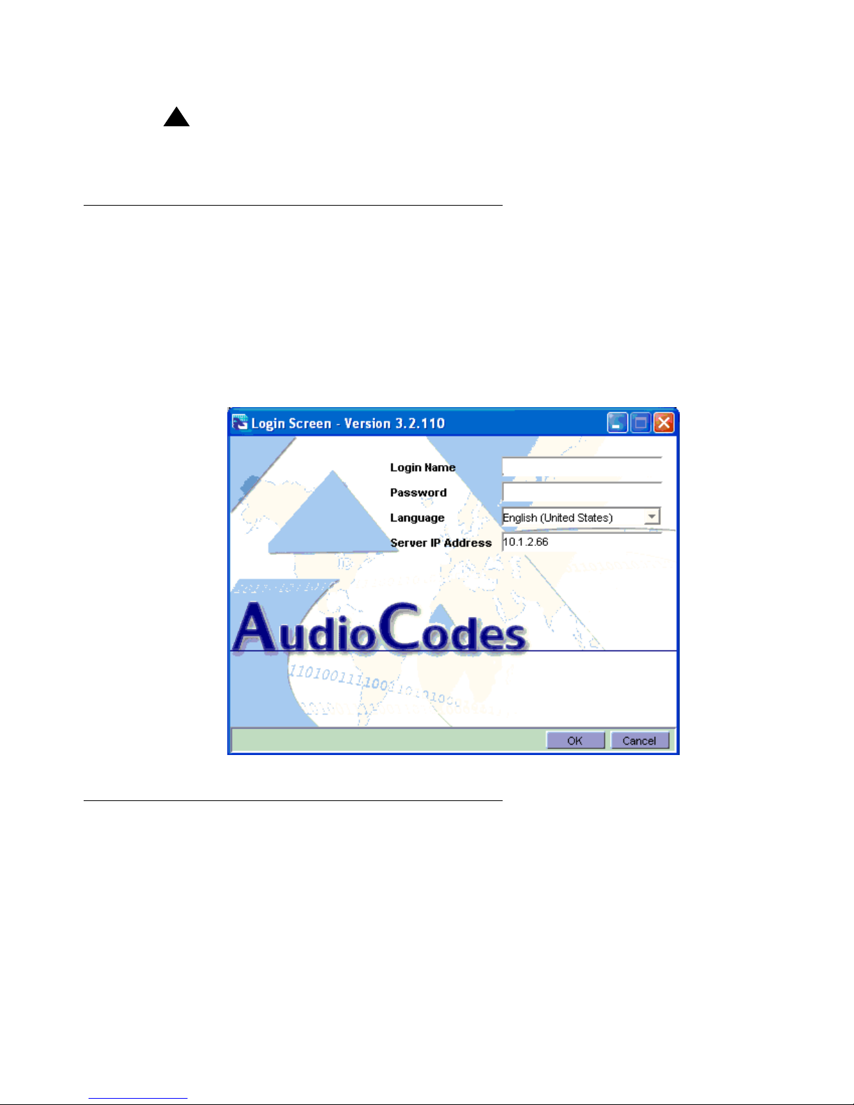
Logging into the EMS
Before starting this procedure, the Element Management System (EMS) server software must
be installed and configured on the Sun server and the EMS clien t so f tware must b e installed on
the Windows 2003 server.
1. Double-click the desktop icon on the computer screen.
2. Type in the login, password, and the server IP address of the EMS server.
Determining feature key file
1. On the menu on the left, click Quick Setup.
6 Avaya G860 Media Gateway Setup 03-601863, Issue 1, November 2007
Page 7
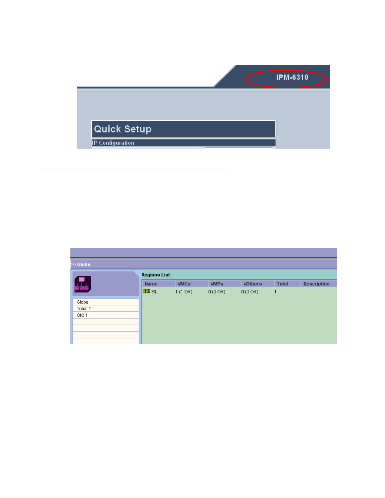
Avaya G860 Media Gateway configuration
2. Look in the upper right-hand corner and make sure it says 6310.
Configuring network support parameters
The main provisioning screen is the logical/geographical area where the media gateway
resides. This procedure configures the IP addresses to be used to access an NTP server and
SNMP trap receivers.
1. On the right pane under Regions List, double-click the first row entry.
Avaya G860 Media Gateway Setup 03-601863, Issue 1, November 2007
7
Page 8
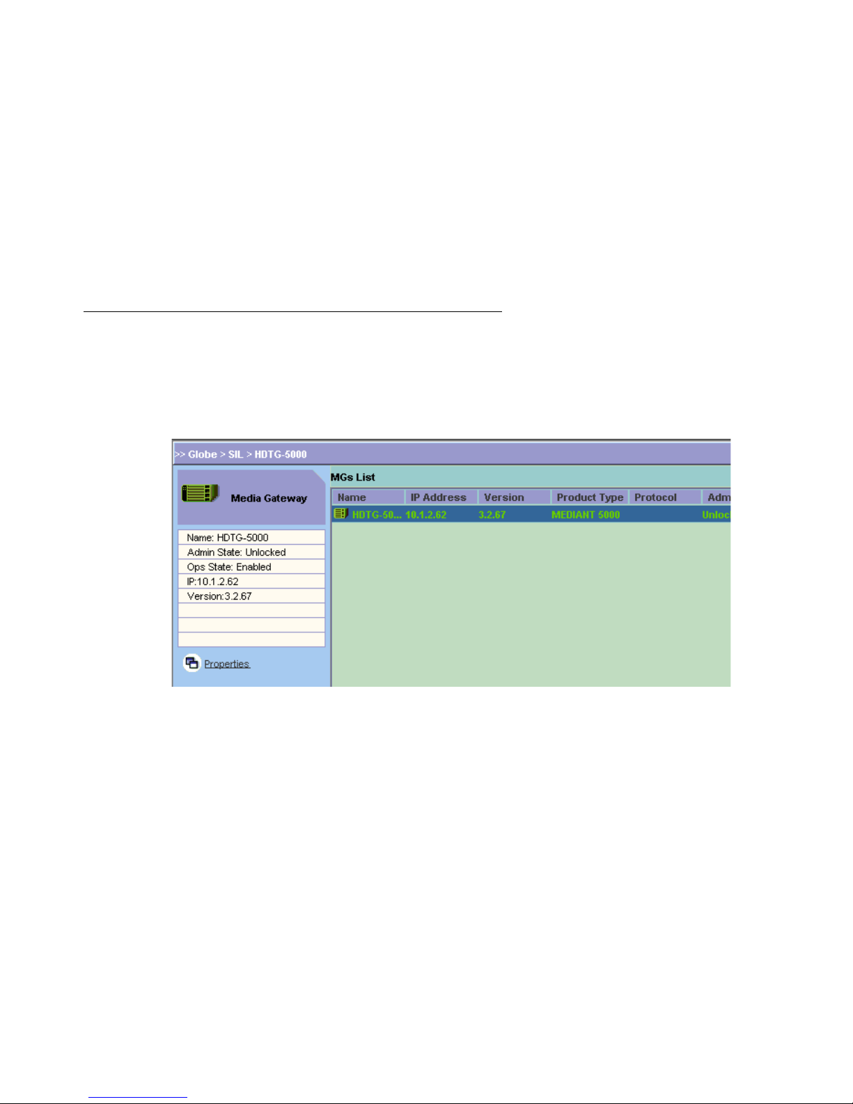
Avaya G860 Media Gateway Setup
2. In the right pane under the MGs List, select the entry corresponding to the Avaya G860
Media Gateway to be configured.
3. Under the Media Gateway pane, click Properties.
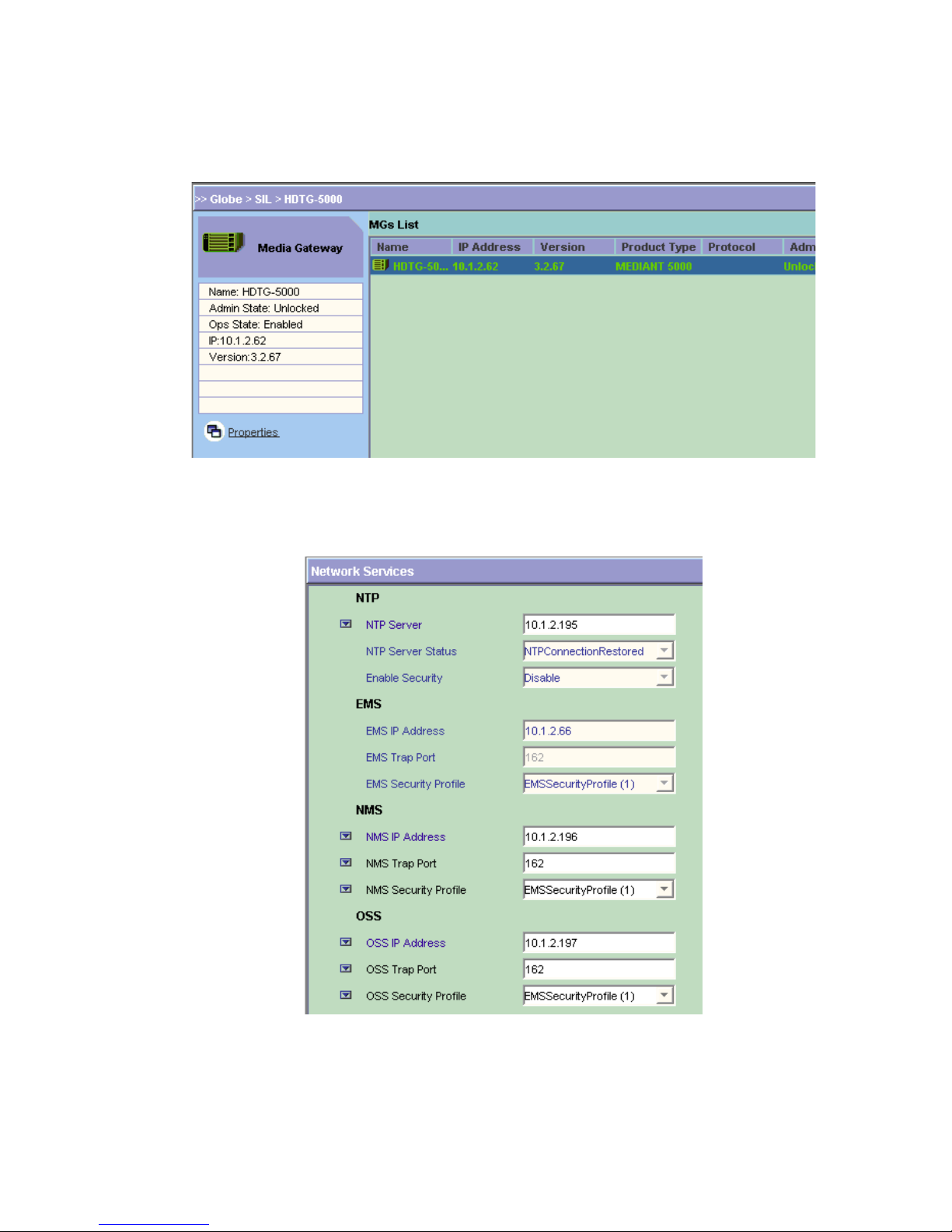
4. Click Network Services.
5. In the NTP server field, type in the IP address for the NTP server.
8 Avaya G860 Media Gateway Setup 03-601863, Issue 1, November 2007
Page 9
6. In the EMS IP Address field, type in the IP address of the trap receiver.
Note:
Note: You can designate 2 SNMP trap receivers by filling in the NMS and OSS sections.
7. In the EMS Trap port field, type in the trap port number (default 162).
8. In the EMS Security Profile field, select EMSSecurityProfile(1).
9. Click Apply and then Close.
Locking the TPM
1. In the right pane under the MGs List, select the entry corresponding to the Avaya G860
Media Gateway to be configured.
Avaya G860 Media Gateway configuration
Avaya G860 Media Gateway Setup 03-601863, Issue 1, November 2007
9
Page 10

Avaya G860 Media Gateway Setup
2. 2. Click on the MG Status tab to display a replica of the front panel.
Board slots are numbered from 1 to 10 from bottom to top, as displayed on the left side of
the front panel. The Trunk Processing Modules (TPM) are in slots 9 and 10.
3. 3. Right-click on the active TPM (TP6310) shown in black and select Maintenance > Lock
4. 4. Click Yes in the confirmation window.
Configuring the TPM parameters
The Trunk Processing Module (TPM [TP6310]) must be locked before starting these steps. See Locking the
TPM on page 9.
1. Double-click on the locked TPM shown in black.
2. Click Properties.
10 Avaya G860 Media Gateway Setup 03-601863, Issue 1, November 2007
Page 11

Avaya G860 Media Gateway configuration
3. Under the Parameters pane on the left, select General Settings.
4. Set the IP Address 1 field to the IP address for this TPM.
5. Set the None Mode Clk Source field to pstn.
6. Set the SSL/TLS Negotiation field to TLSv1Only.
7. Use the default settings for the other fields.
8. Click Apply and Close.
Configuring DS3 trunk on the TPM
The TP6310 board must be locked before starting these steps. See Locking the TPM on page 9.
1. In the right pane under the MGs List, select the entry corresponding to the Avaya G860
Media Gateway to be configured.
2. 2. Select the MG Status tab to display a replica of the front panel.
Avaya G860 Media Gateway Setup 03-601863, Issue 1, November 2007
11
Page 12

Avaya G860 Media Gateway Setup
Board slots are numbered from 1 to 10 from bottom to top, as displayed on the left side of
the front panel. The TPMs are in slots 9 and 10.
3. Double-click on the locked TPM shown in black.
4. In the DS3 tab, double-click on the DS3 entry for the DS1 channel interface parameters
you are configuring.
The DS1 Carriers List pane shows the 28 DS1 interfaces comprising this DS3.
5. Double-click on a particular DS1 interface to set its parameters.
12 Avaya G860 Media Gateway Setup 03-601863, Issue 1, November 2007
Page 13

Avaya G860 Media Gateway configuration
6. Fill in the fields as required by the DS1 service provider.
7. Click Apply.
8. Select the ISDN/DPNSS tab.
9. Set the Termination Side field to the appropriate value.
This is usually userTerminationSide if the PSTN connection is to a service provider.
10. Click Apply.
Tip:
Tip: You can use the Profile Management pane at the bottom to define standard
configuration profiles that you can apply to many DS1 interfaces, saving
configuration steps.
11. Click Save to save this DS1 configuration.
12. In the Profile Name field, type a name for this profile.
13. Click OK.
Avaya G860 Media Gateway Setup 03-601863, Issue 1, November 2007
13
Page 14

Avaya G860 Media Gateway Setup
Configuring SIP trunks on the TPM
The Trunk Processing Module (TPM [TP6310]) must be locked before st arting these steps. See
Locking the TPM
on page 9.
The trunk between the Avaya G860 Media Gateway and Avaya Communication
Transport Layer Security (TLS)1.
1. Double-click on the locked TPM shown in black.
2. Select the SIP tab.
3. Select the Protocol Settings tab
Manager uses
4. In the SIP Destination Port field, type 5061.
5. In the Enable Early Media field, select yes
6. In the Transport Type field, select tls.
7. Click Apply and then Close.
14 Avaya G860 Media Gateway Setup 03-601863, Issue 1, November 2007
Page 15

Avaya G860 Media Gateway configuration
8. Under the SIP tab, select the Coders tab to set the codec preferences to be used on the
SIP calls routed to Avaya Communication Manager.
9. Click on the + icon to add each codec.
Add them in the order of most to least preferred.
10. In the Coders General Settings window, fill in the fields as shown below.
● Name: type a name if desired
● Coder Name: G.711 mu-law 64k
● Packetization Time: 20 ms
Avaya G860 Media Gateway Setup 03-601863, Issue 1, November 2007
15
Page 16

Avaya G860 Media Gateway Setup
● Coder Rate: 64.0
● Payload Type: 0
● St a nce Suppression: Disable
11. Click Apply and then Close.
12. Repeat steps 9 through 12 for each supported codec
Note:
Note: The G860 supports the following codecs: G.711 and G.729.
13. Select the Trunk Groups tab.
14. Click on the + icon to add a trunk group.
15. In the SIP Trunk Groups pane, fill in the fields as shown below.
● Name: All Trunks
● Trunk Group ID: 1
● First Trunk ID: 1
16 Avaya G860 Media Gateway Setup 03-601863, Issue 1, November 2007
Page 17

● Last Trunk ID: 84
● Starting Channel: 1
● Ending Channel: 24
● St arting Phone Number: a 7-digit number. The starting phone number is used when no
ANIinformation is available in incoming PSTN calls. Each DS0 channel in the trunk
group is assigned a unique number based on this starting phone number.
16. Click Apply and then Close to display the SIP Trunk Group List.
17. Select the Trunk Group Settings tab.
18. In the Trunk Group ID and Channel Select Mode fields, fill in the appropriate values.
19. Click Apply and then Close.
Call routing configuration
Similar to Avaya Communication Manager , the Avaya G860 Me dia Gateway must be configured
with SIP and DS3 trunks and with rules to route inbound (DS3 > SIP) and outbound (SIP > DS3)
calls based on information in the incoming call request. You may want to load balance the
incoming traffic from the Avaya G860 Media Gateway across multiple TN799DP C-LAN circuit
packs in the Avaya G650 Media Gateway. All outbound calls should be routed from the
TN799DP C-LAN circuit packs to the Avaya G860 Media Gateway, which routes them to the
DS3 interface on the PSTN side. The routing rules are summarized below.
Avaya G860 Media Gateway configuration
Call Type Routing
Condition
(G860 to/from C-LANs)
Inbound DS3 > SIP > C-LAN1 Last digit of calling
number = 0-4
Inbound DS3 > SIP > C-LAN2 Last digit of calling
number = 5-9
Inbound DS3 > SIP > All All
Outbound C-LANs > SIP > DS3 All
The routing list also has the property that if a call cannot be successfully routed to the
destination specified by a matched rule, then the next rule that matches is used to attempt to
route the call. This can be used implement a failover strategy if one of the TN799DP C-LAN
circuit packs is not responding or not available. For this feature to work most effectively, we
recommend that during maintenance operations, the Ethernet interface be disabled on a
TN799DP C-LAN circuit pack as well as busying it out.
Avaya G860 Media Gateway Setup 03-601863, Issue 1, November 2007
17
Page 18

Avaya G860 Media Gateway Setup
For more information about determining the best routing and alternate routing configurations,
contact an Avaya software specialist.
Configuring inbound call routing on the TPM
The Trunk Processing Module (TPM) must be locked before starting these steps. See Locking
the TPM on page 9.
Note:
Note: The two rules set up in these steps implement a form of loa d sharing that is based
on the calling numbers of the inbound traffic.
1. Double-click the locked TPM shown in black.
2. Select the SIP tab.
3. Select the Routing tab to display the SIP Tel to IP Routing List.
4. Click the + icon to add a routing rule.
Routing rules are applied to inbound calls (DS3 > SIP).
5. In the Name field, type an appropriate name.
6. In the Source Phone Prefix field, type a match specification, where x matches any digit
in the calling number and [x-y] specifies that the digit in hat position should match any
digit in the range x to y.
7. In the Dest Address field, type the IP address of the TN799DP C-LAN circuit pack to
which the incoming PSTN call is sent.
For example, if the last digit of the calling number ends in 0, 1, 2, 3, or 4, then a SIP
INVITE is sent to C-LAN1. See the table in Call Routing Configuration.
8. Click Apply and then Close.
18 Avaya G860 Media Gateway Setup 03-601863, Issue 1, November 2007
Page 19

Avaya G860 Media Gateway configuration
9. Repeat steps 8 and 9, clicking on the + icon to add each rule.
For example, if the last digit of the calling number ends in 5, 6, 7, 8, or 9, then a SIP
INVITE is sent to C-LAN2. See the table in Call Routing Configuration.
10. Select the Routing Setting tab.
11. In the Enable Alternative Routing field, select y.
12. Use the default settings for the other fields.
13. Click Apply and then Close.
The SIP Tel to IP Routing List appears as:
Configuring outbound call routing on the TPM
The Trunk Processing Module (TPM) must be locked before starting these steps. See Locking
the TPM on page 9.
1. Double-click on the locked TPM shown in black.
2. Select the SIP tab.
3. Select the Routing tab
Avaya G860 Media Gateway Setup 03-601863, Issue 1, November 2007
19
Page 20

Avaya G860 Media Gateway Setup
4. Select the IP to Tel tab to display the SIP IP to Tel Routing List.
5. Click the + icon to add a routing rule.
Routing rules are applied to outbound calls (SIP > DS3).
6. In the Name field, type an appropriate name.
7. In the Dest Phone Prefix field, type a match specification.
8. In the Source Phone Prefix field, type a match specification.
9. In the Dest Address field, type a match specification.
For example, if all calls are to be routed to Trunk group 1, type an * in the fields,
specifying a match on any value.
10. In the Trunk Group ID field, type the destination PSTN trunk group number.
20 Avaya G860 Media Gateway Setup 03-601863, Issue 1, November 2007
Page 21

Avaya G860 Media Gateway configuration
11. Click Apply and then Close.
12. Repeat steps 5 through 12, clicking the + icon to add each rule.
13. When done, click the up-arrow icon to return to the MG Status screen.
The SIP IP to Tel Routing List appears as:
Unlocking the TP6310 board
The board must be unlocked for the configuration to be applied to the TP6310 board, after which it is enabled for service.
1. Click the up-arrow icon to display the MG Status screen.
2. In the right pane under the MGs List, select the entry corresponding to the Avaya G860
Media Gateway to be unlocked.
Avaya G860 Media Gateway Setup 03-601863, Issue 1, November 2007
21
Page 22

Avaya G860 Media Gateway Setup
3. Select the MG Status tab to display a replica of the front panel.
Board slots are numbered from 1 to 10 from bottom to top, as displayed on the left side of
the front panel. The TP6310 boards are in slots 9 and 10.
4. Right-click on the active TP6310 card shown in black and select
Maintenance > Unlock
5. Click Yes in the confirmation window.
The TP6310 board resets and returns to service af ter several minutes. The Alarm Browser p ane
at the bottom of the window indicates the status of the board.
Avaya Communication Manager configuration
The following sections describe how to configure call routing in Av aya Communication Manager
for the Avaya G860 Media Gateway. Other information about SIP administration can be found in
the online help that is part of the SIP Administration Web interface.
The first part covers configuring the SIP trunks that communicate with the Avaya G860 Media
Gateway. The second part covers call routing:
● how inbound calls from the Avaya G860 Media Gateway are directly mapped to 5-digit
extensions in Avaya Communication Manager.
● how Automatic Route Selection (ARS) is configured for outbound calls through the Avaya
G860 Media Gateway.
22 Avaya G860 Media Gateway Setup 03-601863, Issue 1, November 2007
Page 23

Verifying system capacities
You must verify that an adequate number of SIP trunk members are administered for the
system.
1. Log into a SAT session as craft or dadmin.
2. Type display system-parameters customer-options and press Enter.
3. Go to the IP Port Capacities page.
4. In the Maximum Administered SIP Trunks field, verify that you have an adequate
number of trunks.
5. In the Maximum TN2602 Boards with 320 VoIP Channels field, verify that you have an
adequate number of channels.
6. In the ARS? field, verify that it is set to y.
Avaya Communication Manager configuration
Assigning IP codec sets
1. Type change ip-codec-set n and press Enter.
2. In the Audio Codec field, type in the codec set you want to use.
For example, type G.711MU for G.711 u-law.
Assigning IP network regions
!
Important:
Important: The authoritative domain must be the same as that used on the signaling group
screen. Domain is case sensitive.
1. Type change ip-network-region and press Enter.
2. In the Authoritative Domain field, type in the desired domain.
For example, type companyx.com.
3. In the Name field, type in a unique name.
4. In the Codec Set field, type in the codec set you want to use for this network region.
5. Set the Intra- and Inter-region IP-IP Direct Audio fields to yes.
Avaya G860 Media Gateway Setup 03-601863, Issue 1, November 2007
23
Page 24

Avaya G860 Media Gateway Setup
Assigning a node name
In Communication Manager, you must first assign a node name and IP address to each active
TPM. This information is used to populate other screens.
1. Type change node-names ip and press Enter.
2. In a blank Name field, type a unique name for the TPM.
3. In the IP Address field, type the IP address of the TPM.
4. Repeat steps 2 and 3 for each additional TPM, if necessary.
5. Press Enter to save your changes
Adding a signaling group
Y ou must a ssign a node name and IP address to active TPM before st arting this procedure. See
Assigning a node nam
IP network regions on page 23.
e on page 24. Y ou must also assign an IP network regio n. See Assigning
You need to create a unique signaling group for each SIP trunk.
1. Type add signaling-group next and press Enter.
The system automatically assigns the next available number.
2. In the Group Type field, type or select sip.
3. Make sure that the value in the Transport Method field is set to tls.
4. In the Near-end Node Name field, type the name of the C-LAN circuit pack to which the
active TPM is registered.
5. In the Far-end Node Name field, type the name of the active TPM.
6. In both the Near-end Listen Port and Far-end Listen Port fields, type 5061.
7. In the Far-end Network Region field, type a network region number if your system is
divided into network regions.
This number is the network region to which the active TPM is assigned.
8. In the Far-end Domain field, type the authoritative domain name for the IP network region
to which the active TPM is assigned.
!
Important:
Important: The Authoritative Domain name on the IP Network Region page and the name in
the Far-end Domain field must match exactly.
9. In the DTMF over IP: field, type rtp-payload.
24 Avaya G860 Media Gateway Setup 03-601863, Issue 1, November 2007
Page 25

10. In the Direct IP-IP Audio Connections?: field, type y.
11. Accept the default values on the remaining fields.
12. Press Enter to save your changes.
If using more than one C-LAN for load balancing, repeat these steps for the each C-LAN.
Adding a trunk group
You must add the active TPM to a signaling group before starting this procedure. See Adding a
signaling group on page 24.
!
Important:
Important: The number of trunk members must be distributed across all the trunk groups
used for the G860 Media Gateway.
1. Type add trunk-group next and press Enter.
Avaya Communication Manager configuration
The system automatically assigns the next available trunk group number, which shows in
the Group Number field.
2. In the Group Type field, type or select sip.
3. In the Group Name field, type a name for this trunk group as it relates to the active TPM.
4. In the COR: field, type 1.
5. In the TAC field, type a valid number that fits your dial plan.
For more information about dial plans in Communication Manager, see the Administrator
Guide for Avaya Communication Manager, 03-300509, at http:// www.avaya.com/support
6. In the Direction field set the value to two-way.
7. In the Service Type field, type or select tie.
8. In the Signaling Group field, type the number of the signaling group to which the active
TPM is assigned.
9. In the Number of Members field, type the number of members that you wish to use for
this trunk group.
Note:
Note: The maximum number of trunk group members in any one signaling group is 2 55.
The maximum number of total members is based upon your license agreement. If
you have more than 255 trunk group members in a signaling group, you must
create additional signaling groups.
.
10. In the Trunk Features section, set the Numbering Format field to public.
Avaya G860 Media Gateway Setup 03-601863, Issue 1, November 2007
25
Page 26

Avaya G860 Media Gateway Setup
11. Accept the default values on the remaining fields.
12. Press Enter to save your changes.
If you have more than one signaling group, repeat these steps for each trunk group.
Defining public numbering format
Avaya Communication Manager must provide the proper calling number when outbound calls
are placed over the SIP trunks. For example, a full 10-digit number includes the CPN prefix plus
5-digit extension.
1. Type change public-unknown-numbering n and press Enter.
2. Fill in all the fields for the number of digits in the extension, the digit with which the
extension starts, and the number of total digits.
Mapping inbound calls (when required)
Inbound calls must be mapped directly to the correct x-digit extensions in Avaya
Communication Manager, if customer requires it.
1. Type change inc-call-handling-trmt trunk-group n and press
Incoming calls arriving at each SIP trunk are routed to the extension specified by the last 5
digits of the called number. The first six digits are deleted if the calling number is of the
form 1AAANNNXXXX, and the first five are deleted for the form AAANNNXXXX.
Mapping outbound calls
Automatic Route Selection (ARS) is used to configure Communication Manager for outbound
calls.
!
Important:
Important: Ensure that all trunk groups are added into any affected routes.
1. Type change dialplan analysis and press Enter to add the feature
outside dialing.
Enter.
access code for
2. Fill in all the fields. For example, type 9 if users must dial 9 to get an outside line, length 1,
and fac for Feature Access Code.
26 Avaya G860 Media Gateway Setup 03-601863, Issue 1, November 2007
Page 27

Verifying network connectivity
3. Type change feature-access-codes and press Enter
4. In the Auto Route Selection (ARS) - Access Code 1 field specify the correct access
code for outside dialing. For example, type 9 if users must dial 9 to get an outside line.
5. Type change ars analysis n and press Enter to configure the route selection based
on the number dialed following the access code.
For example, type 720 if users must dial the area code 720 after dialing 9 for outbound
local calls.
6. Type change route-pattern n and press Enter to define the SIP trunk groups to be
selected for the corresponding route pattern.
7. Set Secure SIP field to N.
8. Type change locations and press Enter.
9. In the Proxy Sel. Rte. Pat. field, designate the SIP trunk routing patterns from step 6. This
provides support for features such as call transfer.
Refer to the Call Routing Guide available on the Avaya Support Web site (h
support.avaya.com) for more information
Ve rifying network connectivity
1. To verify network connectivity on the Avaya G860 Media Gateway:
a. In the right pane under the MGs List, select the entry corresponding to the Avaya
G860 Media Gateway that you configured.
b. Select the MG Status tab to display a replica of the front panel.
c. Double-click on the active TP6310 card shown in black and select
d. Verify that the icons for the DS3 entries are green.
e. Double-click on the DS3 entry for the DS1 channel interface parameters that you
configured.
f. Verify that the icons for the DS1 entries are green.
2. To verify network connectivity on the TN799DP C-LAN circuit packs:
ttp://
a. Log into Communication Manager on the S8720 Media Server and start a SAT
session.
b. Type ping IPAddress board location, where IPAddress is the Ethernet
interface on the G860 Media Gateway and location is the board location of the
C-LAN circuit pack within the G650 Media Gateway.
c. Type status signaling-group and press Enter.
Avaya G860 Media Gateway Setup 03-601863, Issue 1, November 2007
27
Page 28

Avaya G860 Media Gateway Setup
d. Verify that the SIP trunks are up between the A vaya Communication Man ager and the
G860 Media Gateway and that the transport protocols and ports match (TLS and
5061).
Verifying call routing
Verifying call routing means making calls within a session Internet Protocol (SIP) environment
and between SIP and the public switched telephone network (PSTN).
In general, if a SIP device in the network does not receive an expected response to a SIP
message it has transmitted, the standard procedure is to retransmit that message t an
exponentially decreasing interval (0.5 s, then 1 s, etc.) up to 6 more times. Look for this
behavior at various points in the call routing pat h if calls are not successful or if calls only remain
established for about 32 s. Most likely, the expected message was not routed properly because
of NAT, dial-peer, DNS, or firewall configuration errors.
1. Make calls from a telephone on the PSTN to a SIP telephone. If inbound calls fail, verify
that the proper Tel to IP routing rules were defined to support routing SIP calls to the
appropriate C-LANS.
2. Make calls between SIP telephones registered within each proxy to verify successful call
completion.
If outbound calls fail, verify that the proper IP to Tel routing rules were defined to support
routing SIP calls to the appropriate DS3/DS1.
3. Log into a SAT session on the media server.
4. Type list trace station to verify that the call is being properly routed through the
SIP trunk to the G860 Media Gateway.
5. Change the transport protocol to TCP on the SIP trunk and use a SIP-capable protocol
analyzer to monitor the signaling messages.
6. Type change signaling group and press Enter.
7. Change the following fields:
● Transport Method: tcp
● Far-end Listen Port: 5060
8. Log into the G860 Media Gateway.
9. Lock the TPM
10. Double-click on the locked TPM shown in black.
11. Select the SIP tab.
12. Select the Protocol Settings tab
28 Avaya G860 Media Gateway Setup 03-601863, Issue 1, November 2007
Page 29

13. Change the following fields:
● SIP Destination Port tcp
● Transport Type 5060.
14. Click Apply and then Close.
Verifying network connectivity
Avaya G860 Media Gateway Setup 03-601863, Issue 1, November 2007
29
Page 30

Avaya G860 Media Gateway Setup
30 Avaya G860 Media Gateway Setup 03-601863, Issue 1, November 2007
 Loading...