

Page 1

Quick Start
for Hardware Installation:
Avaya S8400 Media Server in an
Avaya G650 Media Gateway
03-300705
Issue 1
February 2006
700385263
Page 2

© 2006 Avaya Inc.
All Rights Reserved.
Notice
While reasonable efforts were made to ensure that
the information in this document was comple te an d
accurate at the time of printing, Avaya Inc. can
assume no liability for any errors. Changes and
corrections to the information in this document may
be incorporated in future releases.
For full legal page information, please see the
complete document, Avaya Legal Page for
Hardware Documentation, document number
03-600759.
To locate this document on our Web site,
simply go to http://www.avaya.com/support
and
search for the document number in the search
box.
Documentation disclaimer
Avaya Inc. is not responsible for any modificat ions,
additions, or deletions to the original published
version of this documentation unless such
modifications, additions, or deletions were
performed by Avaya. Customer and/or End User
agree to indemnify and hold harmless Avaya,
Avaya's agents, servants and employees against
all claims, lawsuits, demands and judgments
arising out of, or in connection with, subsequent
modifications, additions or deletions to this
documentation to the extent made by the Cust omer
or End User.
Warranty
Avaya Inc. provides a limited warranty on this
product. Refer to your sales agreement to establish
the terms of the limited warranty. In addition,
Avaya’s standard warranty language, as well as
information regarding support for this product, while
under warranty, is available through the following
Web site:
http://www.avaya.com/support
.
Copyright
Except where expressly stated otherwise, the
Product is protected by copyright and other laws
respecting proprietary rights. Unauthorized
reproduction, transfer , and o r use can be a crimi nal,
as well as a civil, offense under the applicable law.
Avaya support
Avaya provides a telephone number for you to use
to report problems or to ask questions about your
product. The support telephone number
is 1-800-242-2121 in the United States. For
additional support telephone numbers, see the
Avaya Web site: http://www.avaya.com/support
.
Link disclaimer
Avaya Inc. is not responsible for the contents or
reliability of any linked Web sites referenced
elsewhere within this documentation, and Avaya
does not necessarily endorse the products,
services, or information described or offered within
them. We cannot guarantee that these links will
work all of the time and we have no control over t he
availability of the linked pages.
Page 3
Process and Specifications
1 Verifying the Equipment
2 Installing the Hardware
3 Installing the Circuit Packs
4 Installing the Adapters
5 Connecting the Cables
6 Connecting the Laptop
7 Powering Up the G650
8 Troubleshooting
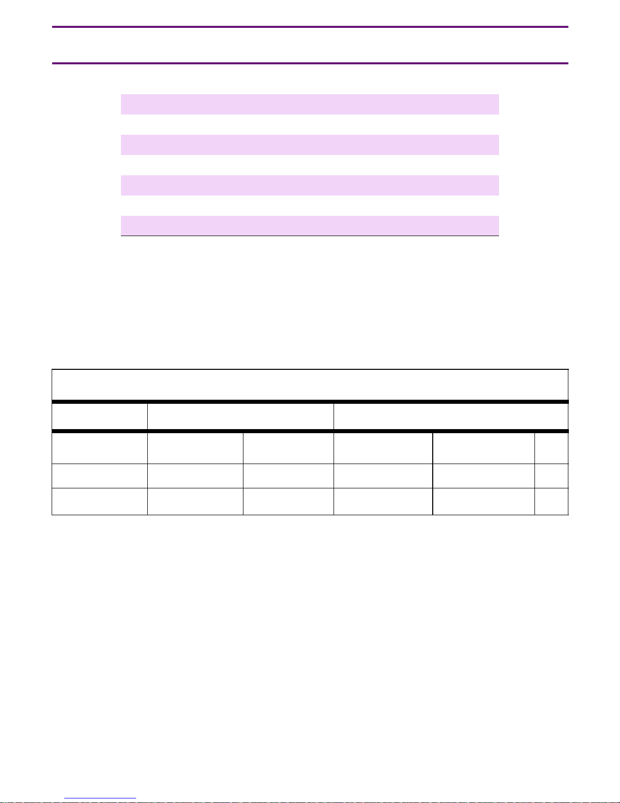
Hardware Specifications
Weight Dimensions
Equipment English (lb) Metric (kg) English (in) Metric (cm) Us
G650 >39 >18 14 x 17.5 x 22 30 x 56 x 48 8
UPS >34 >15 3.5 x 17 x 19 9 x 43 x 48 2
Issue 1 February 2006 3
Page 4
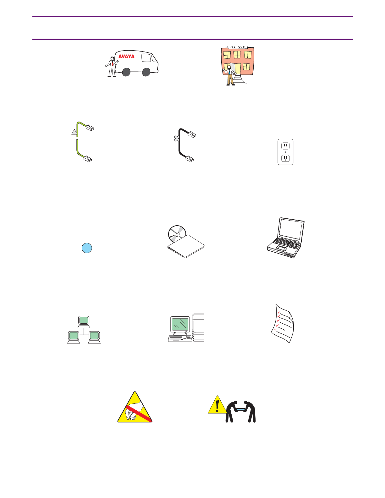
Legend
Avaya technician
or business partner
Customer
Straight-through
CAT5 cable
2
Sequence step
Customer
network
Crossover
cable
Documentation
Product
documentation
System
administration
Nonswitched
electrical outlet
Services
laptop
Filled-out Electronic
Pre-Installation
Worksheet (EPW)
Anti-static wrist
ground strap
required
4 Quick Start for Hardware Installation: S8400 Media Server in a G650 Media Gateway
Warning
Use 2 people
to lift equipment
8400qslg LAO 101405
Page 5
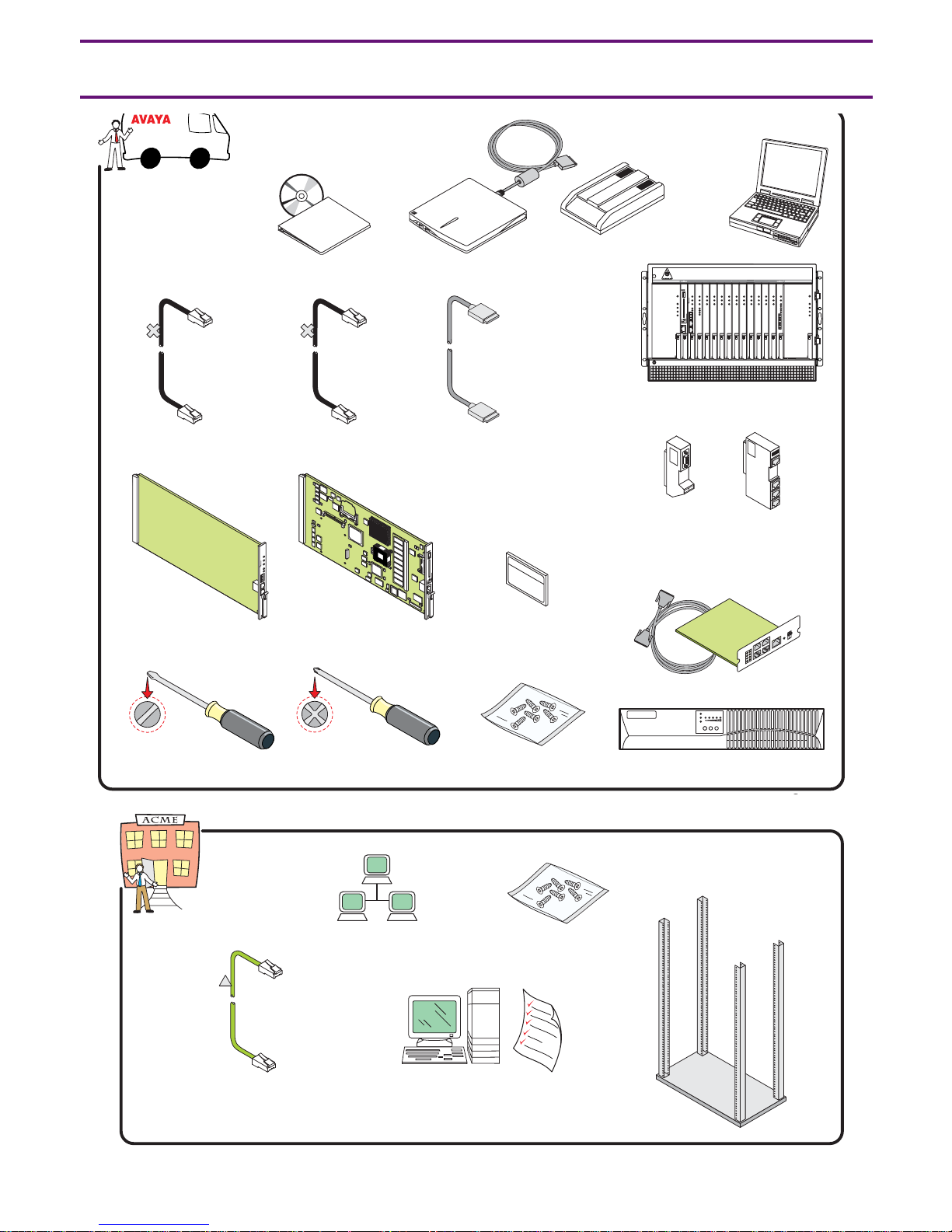
1 Verifying the Equipment
documentation
CAT5 CAT5
IPSI control
network cables
Product
Documentation
(1)
Laptop to
server cable
USB
CD-ROM
(1)
USB modem
E
S
U
IN
D
R
A
C
E
V
O
M
M
R
E
A
L
R
A
TO
K
O
E
IC
V
R
E
S
(1)
cable
Modem
(1)
adapters
Services
laptop
(1)
FAN OR POWER FAIL
FAN AND POWER OK
1
2
E
S
AC INPUT
U
IN
D
E
R
DC INPUT
V
A
O
C
M
E
M
R
ACTIVE RING
R
A
TO
L
K
A
O
E
IC
V
R
E
S
103 456 8 9Power
7 111213 Power
G650 Media Gateway
Cable
RS232 DEBUG
ETHERNET
T
b
0
0
/1
0
1
U
S
B
E
T
H
A
E
T
H
B
E
T
H
C
E
T
H
D
Media server
cable adapter
(3)
(1)
14
FAN OR POWER FAIL
FAN AND POWER OK
AC INPUT
DC INPUT
ACTIVE RING
TN8412AP
circuit pack
Flat-head
screwdriver
CAT5
(1)
TN8400AP
circuit pack
Cross-point
screwdriver
Customer network
Compact
Flash card
(128 Mb)
Screws
Screws
f
f
O
n
O
1 2
SNMP module and cable
UPS (1)
19 in. (48.3 cm)
data rack (1)
Control network
cable
System administration
and filled-out Electronic
Pre-Installation Worksheet (EPW)
Issue 1 February 2006 5
Page 6
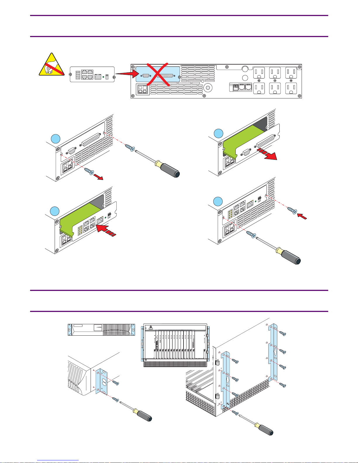
2a Installing the Hardware: SNMP Module*
*If Avaya-supplied UPS
COMM PORT
Off
On
1 2
D
E
T
T
R
A
L
O
O
P
IS
M
R
A
L
1
O
C
3
A
T
R
O
P
M
I
M
IO
IO
ff
O
n
O
1 2
IOIOI
ISOLATED
ALARM PORT
D
E
T
2
O
P
M
I
M
IO
O
C
IO
4
T
R
A
L
O
O
P
IS
M
R
A
L
A
T
R
ff
O
n
O
1 2
85qs2a KLC 021405
2b Installing the Hardware: Mounting Brackets
8400qs2b LAO 101405
FAN OR POWER FAIL
FAN AND POWER OK
1
2
AC INPUT
DC INPUT
ACTIVE RING
103 456 8 9Power
7 111213 Power
14
FAN OR POWER FAIL
FAN AND POWER OK
ACTIVE RING
AC INPUT
DC INPUT
Power
6 Quick Start for Hardware Installation: S8400 Media Server in a G650 Media Gateway
Page 7

2c Installing the Hardware: Carrier Address Settings
2
E
D
C
B
A
E
D
C
B
A
E
D
C
B
A
E
D
C
B
A
TOP
E
D
C
B
A
3
8400qs2c LAO 101405
4
1
2
5
Issue 1 February 2006 7
Page 8

2d Installing the Hardware: Door Removal
1
P
o
w
e
r
FA
FA
1
N
O
R
P
N
A
N
D
P
AC
2
O
W
E
R
F
O
W
E
R
AC
IN
P
D
C
IN
P
T
IV
E
R
IN
3
A
IL
O
K
U
T
U
T
G
3
4
5
6
7
8
9
1
0
1
1
1
2
1
3
1
4
1
P
o
w
e
r
FA
N
O
R
P
O
W
E
R
FA
F
N
A
A
IL
N
D
P
O
W
E
R
O
AC
K
IN
P
U
D
T
C
IN
AC
P
T
U
IV
T
E
R
IN
G
2
8400qs2d LAO 101605
8 Quick Start for Hardware Installation: S8400 Media Server in a G650 Media Gateway
Page 9

2e Installing the Hardware: Rack Installation
P
o
w
e
r
P
o
w
e
r
1
2
3
4
5
6
7
8
9
1
0
1
1
1
2
1
3
1
4
P
o
w
e
r
P
o
w
e
r
1
2
3
4
5
6
7
8
9
1
0
1
1
1
2
1
3
1
4
P
o
w
e
r
8400qs2e LAO 100305
Issue 1 February 2006 9
Page 10

2f Installing the Hardware: Ringer Switch Settings
2
4
OKTO REMOVE
Power
1
1
5
2
CARD IN USE
ALARM
SERVICE
3
4
5
3
OFF 25HZ 20HZ
10 Quick Start for Hardware Installation: S8400 Media Server in a G650 Media Gateway
OFF 25HZ 20HZ
8400qs2f LAO 101605
Page 11

3 Installing the Circuit Packs
2
T
T
T
T
N
8
4
1
2
A
1
P
N
8
4
0
0
A
P
N
7
9
9
D
P
3
N
7
7
1
Pow
er
FA
N
FA
N
T
N
2
T
6
N
0
2
2
3
A
0
P
2
A
P
1
O
R
PO
W
A
N
D
P
O
AC
D
AC
T
IV
2
E
R
F
A
W
E
R
O
IN
PU
C
IN
P
U
E
R
IN
3
IL
K
T
T
G
4
5
6
7
8
9
10
1
1
12
13
14
Pow
er
FA
N
O
R
P
O
W
E
R
FA
F
N
A
A
IL
N
D
P
O
W
E
R
O
AC
K
IN
P
U
D
T
C
IN
AC
P
T
U
IV
T
E
R
IN
G
8400qs3b LAO 102005
Issue 1 February 2006 11
Page 12

4 Installing the Adapters
G
U
B
E
D
32
S2
R
U
S
B
E
T
H
-A
T
E
N
R
E
H
T
E
T
b
0
0
/1
0
1
E
T
H
-B
E
T
H
-C
E
T
H
-D
UG
B
E
232 D
S
R
T
E
N
R
E
H
T
E
T
0b
/10
0
1
8400qs4 LAO 101605
G
U
EB
2 D
23
S
R
T
E
N
R
E
H
T
E
T
b
0
0
/1
0
1
12 Quick Start for Hardware Installation: S8400 Media Server in a G650 Media Gateway
Page 13

5 Connecting the Cables
01
USB
ETH-A
ETH-B
ETH-C
ETH-D
U
S
B
E
T
H
A
E
T
H
B
E
T
H
C
E
T
H
D
01
5
3
6
Off
On
1 2
8400qs5 LAO 102105
A
-48VDC
-48VDC
RETURN
01
U
S
B
E
T
H
-
A
E
T
H
-
B
E
T
H
-
C
E
T
H
-
D
3
4
1
2
Issue 1 February 2006 13
Page 14

6a Connecting the Laptop: Configuring the UPS*
*If Avaya-supplied UPS
Off
On
1 2
A
1
-48VDC
-48VDC
RETURN
01
U
S
B
E
T
H
A
E
T
H
B
E
T
H
-C
E
T
H
-D
2
Documentation
3
8400qs6a LAO 102005
14 Quick Start for Hardware Installation: S8400 Media Server in a G650 Media Gateway
Page 15

6b Connecting the Laptop: Configuring the Media Server
Power
2
1
ALA
OK T
SERVICE
AL
O
K
SERVIC
E
2
1
FAN OR POWER FAIL
FAN AND POWER OK
AC INPUT
DC INPUT
ACTIVE RING
1
2
SE
U
D IN
VE
O
CAR
KTO REM
ALARM
O
E
SERVIC
103 456 8 9Power
7 111213 Power
14
FAN OR POWER FAIL
FAN AND POWER OK
AC INPUT
DC INPUT
ACTIVE RING
3
Documentation
4
8400qs6b LAO 101605
Issue 1 February 2006 15
Page 16

7 Powering up the G650
Off
On
1 2
1
A
US
B
E
T
H
-A
E
T
H-B
E
T
H-C
E
T
H
-D
-48VDC
-48VDC
RETURN
2
8400qs7 LAO 101605
16 Quick Start for Hardware Installation: S8400 Media Server in a G650 Media Gateway
Page 17

8 Troubleshooting
Problem: Solution:
● Avaya equipment is missing ● Contact the project manager
● Customer equipment is missing ● Contact the project manager
● Customer network information is missing ● Contact the project manager
● No power to the UPS ● Is the UPS plugged into the outlet?
● Does the outlet have power?
● The alarm LEDs on the UPS are flashing ● Refer to the UPS user’s guide
● No power to the media server ● Is the media server plugged into the UPS?
● Does the UPS have power?
● Is the TN8400AP fully seated?
● No V on the TN8412AP SIPI LCD ● Check the connection to the network
● Check the connection to the TN8400AP
Issue 1 February 2006 17
Page 18

18 Quick Start for Hardware Installation: S8400 Media Server in a G650 Media Gateway
 Loading...