

Page 1

For bulk discounts, product demonstrations, free product
trials & world-wide Avaya orders, please contact:
Telefonix Voice & Data
UK (+44) 01252 333 888
info@telefonix.co.uk
http://www.telefonix.co.uk/
Page 2

Overview for the Avaya G450 Media
Gateway
03-602058
January 2008
Issue 1
Page 3

© 2008 Avaya Inc.
All Rights Reserved.
Notice
While reasonable efforts were made to ensure that the inform ation in this
document was complete and accurate at the time of printing, Avaya Inc. can
assume no liability for any errors. Changes and corrections to the information
in this document may be incorporated in future releases.
For full legal page information, please see the complete document, A v aya
Legal Page for Software Documentation, Document number 03-600758.
To locate this document on the website, simply go to
http://www.avaya.com/support
the search box.
Documentation disclaimer
Avaya Inc. is not responsible for any modifications, additions, or deletions to
the original published version of this documentation unless such modifications,
additions, or deletions were performed by Avaya. Customer and/or End User
agree to indemnify and hold harmless Avaya, Avaya's agents, servants and
employees against all claims, lawsuits, demands and judgments arising out of,
or in connection with, subsequent modifications, additions or deletions to this
documentation to the extent made by the Customer or End User.
Link disclaimer
Avaya Inc. is not responsible for the contents or reliability of any linked web
sites referenced elsewhere within this documentation, and Avaya does not
necessarily endorse the products, services, or informa tion described or o f fered
within them. We cannot guarantee that these links will work all of the time and
we have no control over the availability of the linked pages.
Warranty
Avaya Inc. provides a limited warranty on this product. Refer to your sales
agreement to establish the terms of the limited warranty. In addition, Avaya’s
standard warranty language, as well as information regarding support for this
product, while under warranty, is available through the following web site:
http://www.avaya.com/support
Copyright
Except where expressly stated otherwise, the Product is protected by copyrigh t
and other laws respecting proprietary rights. Unauthorized reproduction,
transfer, and or use can be a criminal, as well as a civil, offense un der the
applicable law.
Avaya support
Avaya provides a telephone number for you to use to report problems or t o ask
questions about your product. The support telephone number
is 1-800-242-2121 in the United States. For additional support telephone
numbers, see the Avaya web site:
http://www.avaya.com/support
and search for the document number in
Page 4

Contents
About this book . . . . . . . . . . . . . . . . . . . . . . . . . . . . . . . 5
Audience . . . . . . . . . . . . . . . . . . . . . . . . . . . . . . . . . . . . . . . . 5
Downloading this book and updates from the web . . . . . . . . . . . . . . . . . 5
Downloading this book . . . . . . . . . . . . . . . . . . . . . . . . . . . . . . 5
Related resources . . . . . . . . . . . . . . . . . . . . . . . . . . . . . . . . . . . 6
Technical assistance . . . . . . . . . . . . . . . . . . . . . . . . . . . . . . . . . 6
Within the US. . . . . . . . . . . . . . . . . . . . . . . . . . . . . . . . . . . . 6
International . . . . . . . . . . . . . . . . . . . . . . . . . . . . . . . . . . . . 6
Sending us comments. . . . . . . . . . . . . . . . . . . . . . . . . . . . . . . . . 7
Chapter 1: Introduction . . . . . . . . . . . . . . . . . . . . . . . . . . . 9
Features . . . . . . . . . . . . . . . . . . . . . . . . . . . . . . . . . . . . . . . . 10
G450 physical description . . . . . . . . . . . . . . . . . . . . . . . . . . . . . . 13
Chapter 2: Optional components. . . . . . . . . . . . . . . . . . . . . . 15
Supported media modules in the G450 . . . . . . . . . . . . . . . . . . . . . . . 15
S8300 server . . . . . . . . . . . . . . . . . . . . . . . . . . . . . . . . . . . . 16
Telephony media modules . . . . . . . . . . . . . . . . . . . . . . . . . . . . 17
WAN media modules . . . . . . . . . . . . . . . . . . . . . . . . . . . . . . . 22
Media module slot configurations in the G450 . . . . . . . . . . . . . . . . . . . 23
Permitted slots. . . . . . . . . . . . . . . . . . . . . . . . . . . . . . . . . . . 23
G450 media module capacity . . . . . . . . . . . . . . . . . . . . . . . . . . . 24
Chapter 3: Summary of services . . . . . . . . . . . . . . . . . . . . . . 25
Media gateway services. . . . . . . . . . . . . . . . . . . . . . . . . . . . . . . . 25
Voice over IP (VoIP) . . . . . . . . . . . . . . . . . . . . . . . . . . . . . . . . 25
Physical media — G450 . . . . . . . . . . . . . . . . . . . . . . . . . . . . . . 26
Media Gateway Controllers . . . . . . . . . . . . . . . . . . . . . . . . . . . . 27
Additional features . . . . . . . . . . . . . . . . . . . . . . . . . . . . . . . . 30
LAN services. . . . . . . . . . . . . . . . . . . . . . . . . . . . . . . . . . . . . . 31
Physical media. . . . . . . . . . . . . . . . . . . . . . . . . . . . . . . . . . . 31
VLANs . . . . . . . . . . . . . . . . . . . . . . . . . . . . . . . . . . . . . . . 31
Rapid Spanning Tree Protocol (RSTP) . . . . . . . . . . . . . . . . . . . . . . 32
Port mirroring . . . . . . . . . . . . . . . . . . . . . . . . . . . . . . . . . . . 32
Port redundancy . . . . . . . . . . . . . . . . . . . . . . . . . . . . . . . . . . 32
Link Layer Discovery Protocol (LLDP) . . . . . . . . . . . . . . . . . . . . . . 32
WAN services . . . . . . . . . . . . . . . . . . . . . . . . . . . . . . . . . . . . . 32
Physical media. . . . . . . . . . . . . . . . . . . . . . . . . . . . . . . . . . . 33
WAN features . . . . . . . . . . . . . . . . . . . . . . . . . . . . . . . . . . . 34
Issue 1 January 2008 3
Page 5

Contents
Routing features . . . . . . . . . . . . . . . . . . . . . . . . . . . . . . . . . . 35
Chapter 4: Management, Security, Alarms and Troubleshooting . . . . 37
Management applications. . . . . . . . . . . . . . . . . . . . . . . . . . . . . . . 37
Avaya G450 Command Line Interface (CLI) . . . . . . . . . . . . . . . . . . . 37
Avaya G450 Manager and Embedded Web Manager . . . . . . . . . . . . . . 37
Avaya Integrated Management . . . . . . . . . . . . . . . . . . . . . . . . . . 38
Management access security features. . . . . . . . . . . . . . . . . . . . . . . . 38
Network security features. . . . . . . . . . . . . . . . . . . . . . . . . . . . . . . 38
Alarms and troubleshooting features . . . . . . . . . . . . . . . . . . . . . . . . 39
Front panel LEDs . . . . . . . . . . . . . . . . . . . . . . . . . . . . . . . . . 39
Automatic error detection. . . . . . . . . . . . . . . . . . . . . . . . . . . . . 39
SNMP . . . . . . . . . . . . . . . . . . . . . . . . . . . . . . . . . . . . . . . . 40
Packet sniffing . . . . . . . . . . . . . . . . . . . . . . . . . . . . . . . . . . . 40
VoIP debugging using RTP-MIB . . . . . . . . . . . . . . . . . . . . . . . . . 40
Converged Network Analyzer (CNA) test plug. . . . . . . . . . . . . . . . . . 40
Chapter 5: Documentation . . . . . . . . . . . . . . . . . . . . . . . . . 41
Appendix A: G450 capacities. . . . . . . . . . . . . . . . . . . . . . . . 43
G450 maximum media gateway capacities . . . . . . . . . . . . . . . . . . . . . 43
S8300 maximum capacities . . . . . . . . . . . . . . . . . . . . . . . . . . . . . . 45
Appendix B: Supported Avaya telephones . . . . . . . . . . . . . . . . 47
Appendix C: G450 technical specifications . . . . . . . . . . . . . . . . 49
G450 specifications . . . . . . . . . . . . . . . . . . . . . . . . . . . . . . . . . . 49
G450 power cord specifications . . . . . . . . . . . . . . . . . . . . . . . . . . . 50
G450 media module specifications. . . . . . . . . . . . . . . . . . . . . . . . . . 50
Index . . . . . . . . . . . . . . . . . . . . . . . . . . . . . . . . . . 51
4 Administration for the Avaya G450 Media Gateway
Page 6

About this book
This guide contains information that you need to consider before implementing the A vaya G450
Media Gateway. Use this guide to learn what the G450 can d o and to plan how you will deploy a
G450 in your environment.
Audience
The information in this book is intended for use by Avaya technicians, provisioning specialists,
Business Partners, and customers.
Downloading this book and updates from the web
You can download the latest version of Overview for the Avaya G450 Media Gateway from the
Avaya web site. You must have access to the Internet, and a copy of Acrobat Reader must be
installed on your personal computer.
Avaya makes every effort to ensure that the information in this book is complete and accurate.
However, information can change after we publish this book. Therefore, the Avaya web site
might also contain new product information and updates to the information in this book. You can
also download these updates from the Avaya web site.
Downloading this book
1. Access the Avaya web site at http://www.avaya.com/support.
2. Click FIND DOCUMENTATION and TECHNICAL INFORMATION by PRODUCT NAME.
3. Type this book’s document number (03-602058) in the Search box.
4. Click GO.
The search results appear.
5. Locate the latest version of the book.
6. Click the book title. Your browser downloads the book.
Issue 1 January 2008 5
Page 7

About this book
Related resources
Title Number
Quick Start for Hardware Installation for the Avaya G450 Media
Gateway
Installing and Upgrading the Avaya G450 Media Gateway 03-602054
Administration for the Avaya G450 Media Gateway 03-602055
Avaya G450 CLI Reference 03-602056
Maintenance Alarms for Avaya Communication Manager,
Media Gateways and Servers
Maintenance Commands for Avaya Communication Manager,
Media Gateways and Servers
Maintenance Procedures for Avaya Communication Manager,
Media Gateways and Servers
Technical assistance
Avaya provides resources for technical assistance within the US and internationally.
03-602053
03-300430
03-300431
03-300432
Within the US
For help with:
● Feature administration and system applications, call the Avaya Technical Consulting
Support System at 1-800-225-7585
● Maintenance and repair, call the Avaya National Customer Care Support Line at
1-800-242-2121
● Toll fraud, call Avaya Toll Fraud Intervention at 1-800-643-2353
International
For all international resources, contact your local Avaya authorized dealer.
6 Administration for the Avaya G450 Media Gateway
Page 8

Sending us comments
Avaya welcomes your comments about this book. To reach us by:
● Mail, send your comments to:
Avaya Inc.
Product Documentation Group
Room B3-H13
1300 W. 120th Ave.
Westminster, CO 80234 USA
● E-mail, send your comments to:
document@avaya.com
● Fax, send your comments to:
1-303-538-1741
Sending us comments
Ensure that you mention the name and number of this book, Overview for the Avaya G450
Media Gateway, 03-602058.
Issue 1 January 2008 7
Page 9

About this book
8 Administration for the Avaya G450 Media Gateway
Page 10

Chapter 1: Introduction
The Avaya G450 Media Gateway is a multipurpose media gateway that can be deployed in
medium to large sized branch locations or in wiring-closets servicing buildings and floors, in a
campus environment. It works in conjunction with Avaya Communication Manager IP telephony
software running on Avaya S8XXX Servers to help deliver intelligent communications to
enterprises of all sizes.
The G450 combines telephone exchange and data networking, by providing PSTN toll bypass
and routing data and VoIP traffic over the WAN. The G450 features a VoIP engine, an optional
WAN router, and Ethernet LAN connectivity. The G450 provides full support for Avaya IP and
digital telephones, as well as analog devices such as modems, fax machines, and telephones.
The G450 can support up to 450 users when deployed as a branch gateway in a mid to large
branch office of a large enterprise or a call center, and can serve up to 2400 users when
deployed as a campus gateway . Both configura tions require Avaya Communication Manager IP
telephony software running on one or more Avaya S8XXX Servers. The 450 user capacity is
reached when the Avaya S8300 server is used and the 2400 use r cap acity is reached when the
Avaya S8500 Server is used.
Telephone services on a G450 are controlled by an Avaya S8XXX Server operating either as an
External Call Controller (ECC) or as an Internal Call Controller (ICC). The G450 supports the
Avaya S8300 Server as an ICC, or as an ECC when the S8300 is installed in another media
gateway . The G450 also support s the Avaya S8710, S8720, S8730, S8500, and S8400 Servers
as ECCs.
An ICC can be used in addition to an ECC with the ICC installed as a Local Survivable
Processor (LSP) designed to take over call control in the event that the ECC fails or the WAN
link between the branch office and main location breaks. The LSP provides full featured
telephone service survivability for the branch office. The G450 itself also features Standard
Local Survivability (SLS), which provides basic telephone services in the event that the
connection with the primary ECC is lost.
The G450 is a scalable device with a basic configuration consisting of 1 power supply unit
(PSU), 256 MB RAM, and a single DSP childboard supporting either 20 or 80 VoIP channels.
This configuration can be enhanced by adding a redundant PSU, up to two RAM modules of
1 GB each, and up to three additional DSP childboards, increasing the number of VoIP
channels to 240 channels.
Issue 1 January 2008 9
Page 11

Introduction
The G450 is a modular device, adaptable to support different combinations of en dpoint devices.
While fixed front panel ports support the connection of external LAN switches, network data
ports, Ethernet WAN lines and external routers, eight slo ts are provided for plugging in optional
media modules. Pluggable media modules provide interfaces for different types of telephones,
trunks, and WAN links. A combination is selected to suit the needs of the branch. A range of
telephony modules provides full support for legacy equipment such as analog and digital
telephones. A range of WAN modules provide supp ort for Universal Serial Port and E1/T1 W AN
links. IP phones are supported via an external LAN switch.
The G450 chassis features field replaceable RAM, DSPs, PSUs, fan tray, and main board
module for enhanced reliability.
Features
G450 features include:
● Modular gateway features:
- 9-slot chassis (one slot for main board and eight slots for media modules)
- Swappable main board module
- Hot swappable media modules
- Support for two load sharing hot swappable power supply units
- Hot swappable fan tray
- VoIP DSPs (up to 240 channels)
- Memory SIMMs
● Voice features:
- H.248 gateway
- Voice line interfaces:
● IP phones
● Analog phones
● Avaya DCP phones
● BRI Phones
● FXS/Fax
● VoIP
● Fax and modem over IP
- Voice trunk interfaces:
● FXO
● BRI
10 Administration for the Avaya G450 Media Gateway
Page 12

● T1/E1
- Supported CODECs: G.711A/µLaw, G.729a, G.726
- Survivability features for continuous voice services:
● Local Survivable Processor (LSP) (with S8300)
● Standard Local Survivability (SLS)
● Emergency Transfer Relay (ETR)
● Modem Dial Backup
● Dynamic Call Admission Control (CAC) for Fast Ethernet, Serial, and GRE tunnel
interfaces
● Inter-Gateway Alternate Routing (IGAR)
- DHCP and TFTP server to support IP phones images and configuration
- Announcements and Music on Hold (MoH) support
- Contact Closure support
● Routing and WAN features:
Features
- Two WAN 10/100 Ethernet ports with traffic shaping capabilities
- T1/E1 and USP interfaces
- PPPoE, Frame-relay, and PPP
- Routing Protocols: Static, OSPF, RIP
- VRRP
- Equal Cost Multi Path routing (ECMP)
- IPSec VPN (requires license)
-cRTP
- WAN Quality of Service (QoS)
- Policy-based routing
- DHCP relay
- GRE tunneling
- Dynamic IP addressing (DHCP client/PPPoE)
- Object tracking
- Backup Interface
● LAN features:
- Two LAN 10/100/1000 RJ-45 Ethernet ports (w/o POE)
- Auto-negotiation
- 4K MAC table with aging
-64 VLANs
Issue 1 January 2008 11
Page 13

Introduction
● Security hardened gateway features:
- Multi-VLAN binding, 802.1Q support
- Ingress VLAN Security
- Broadcast/Multicast storm control
- Automatic MAC address aging
- Rapid Spanning Tree
- Port mirroring
-RMON statistics
- Port redundancy
-LLDP
- Media and signaling encryption
- Secured management
- Digitally signed gateway firmware
- Managed security service support
- Access list support
● Management features:
- Avaya G450 Device Manager
- Embedded Web Manager
- RADIUS Authentication support
- SNMPv1 traps and SNMPv3 notifications
- Telnet and SSHv2 support
- SCP, TFTP and FTP support
-Syslog
- Modem access for remote administration
- Converged Network Analyzer (CNA) test plug
- Packet Sniffing
-RTP-MIB
- Backup and Restore on Flash drive
12 Administration for the Avaya G450 Media Gateway
Page 14
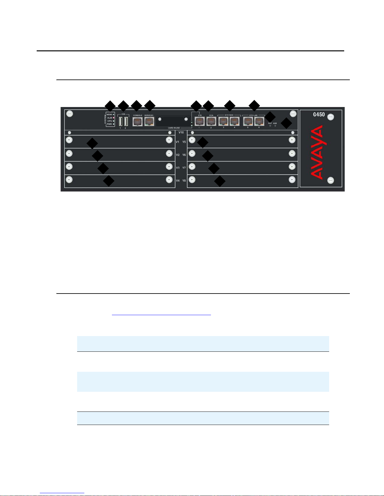
G450 physical description
Figure 1: The Avaya G450 Media Gateway Chassis
G450 physical description
4
3
2
1
11
12
13
14
Figure notes:
1. System LEDs
2. USB ports
3. Console port
4. Services port
5. ETR (Emergency Transfer Relay) port
6. CCA (Contact Closure Adjunct) port
7. ETH WAN ports
8. ETH LAN ports
9. RST button
10. ASB button
6
5
15
16
11. V1 — slot for standard media module or
S8300 Server
12. V2 — standard media module slot
13. V3 — standard media module slot
14. V4 — standard media module slot
15. V5 — standard media module slot
16. V6 — standard media module slot
17. V7 — standard media module slot
18. V8 — standard media module slot
7
17
18
8
9
10
For information about the different media modules that can be housed in the G450 media
module slots, see Chapter 2:
Optional components.
Table 1: Fixed ports and buttons on the G450 front panel
Port/Button Description
CCA RJ-45 port for ACS (308) contact closure adjunct
box.
ETH WAN Two 10/100 Base TX Ethernet WAN ports. RJ-45
connectors.
ETH LAN Two 10/100/1000 Base TX Ethernet LAN ports.
RJ-45 connectors.
1 of 2
Issue 1 January 2008 13
Page 15

Introduction
Table 1: Fixed ports and buttons on the G450 front panel (continued)
Port/Button Description
CONSOLE RS-232 port for services and maintenance access.
RJ-45 connector.
SERVICES Ethernet 10/100 port for services and maintenance
access. RJ-45 connector.
ETR Emergency Transfer Relay port. Controls two
external 808A emergency transfer panels. RJ-45
connector.
USB Two USB ports with USB connectors. Support s the
connection of:
● USB flash drive (no more than one USB
flash drive can be connected)
● The Multitech MultiModemUSB
MT5634ZBA-USB-V92 USB modem (no
more than one USB modem can be
connected)
RST Reset button. Resets chassis configuration.
ASB Alternate Software Bank button. Reboots t he G450
with the software image in the alternate bank.
2 of 2
14 Administration for the Avaya G450 Media Gateway
Page 16

Chapter 2: Optional components
The Avaya G450 Media Gateway is a versatile device with powerful capabilities. To implement
the various services that are supported, a variety of swappable internal components called
media modules are available.
Supported media modules in the G450
Table 2: Supported media modules
Media module Description
S8300 CM server
Telephony media modules
MM711 8 universal analog ports
MM714 4 analog telephone ports and 4 analog trunk ports
MM716 24 analog ports
MM712 8 DCP telephone ports
MM717 24 DCP telephone ports
MM710 1 T1/E1 ISDN PRI trunk port
MM720 8 ISDN BRI trunk or endpoint (telephone or data) ports
MM722 2 ISDN BRI trunk ports
WAN media modules
MM340 1 E1/T1 data WAN port
MM342 1 universal serial data WAN port
Issue 1 January 2008 15
Page 17

Optional components
!
CAUTION:
CAUTION: The MM340 and MM342 are not supported by the Avaya G700 Media Gateway.
Do not insert an MM340 or MM342 media module into an Avaya G700 Media
Gateway.
S8300 server
The S8300 server is a Pentium-based processor that runs a Linux operating system. The G450
supports the S8300 from version S8300B onwards. The S8300 runs Avaya Communication
Manager (CM) to provide call control services to the G450. The G450 is compatible with Avaya
CM from version 5.0.
The S8300 server features:
● Avaya Native Configuration Manager. An administration tool that provides terminal
emulation capabilities and a variety of connectivity options you can save and reuse.
● A 30GB hard disk
● 512 MB RAM
● A WEB server used for the following:
- Backups and restores for customer data
- Easy access to view current alarms
- The ability to perform server maintenance, shutdown, and status of the S8300 server
- Security commands that can enable and disable the modem, start and stop the FTP
server, and view the software license
- SNMP access to configure trap destinations and stop and start the master agent
- S8300 server configuration information and upgrade access
- The ability to download the Avaya Native Configuration Manager from the S8300
server to a PC on the LAN
● Linux operating system (Redhat v8.x)
● Interface for IA770 INTUITY AUDIX Messaging, a software-only version of INTUITY
AUDIX messaging that resides on the hard drive of the S8300 server. For more
information, see the description of the S8300 server in the Hardware Description and
Reference for Avaya Communication Manager, 555-245-207.
● Trivial File Transfer Protocol (TFTP) server
● Security/firewall configuration
● H.248 Media Gateway Signaling Protocol
● Control messages tunneled over H.323 Signaling Protocol
● One 10/100Base-T Ethernet switch port used as a Services port
16 Administration for the Avaya G450 Media Gateway
Page 18

● Two USB ports for modem connections
● SNMP alarming
● Support for remote call out alarming
Figure 2: The S8300 server
Telephony media modules
The G450 supports the MM711, MM714, and MM716 analog media modules, the MM712 and
MM717 DCP media modules, the MM710 E1/T1 media module, and the MM720 and MM722
BRI media modules.
Supported media modules in the G450
MM711 analog media module
The MM711 provides analog trunk and telephone features and functionality.
Configuring MM711 ports
The administrator can configure any of the eight ports of the MM711 as follows:
● Central office trunk, either loop start or ground start
● Analog Direct Inward Dialing (DID) trunks, either wink-start or immediate-start
● 2-wire analog Outgoing CAMA E911 trunks for connectivity to the PSTN
● MF signaling is supported for CAMA ports
● Analog, tip/ring devices, such as single-line telephones with or without LED message
waiting indication
MM711 also supports
● Three ringer loads (ringer equivalency number) for up to 2,000 feet (610 meters) for all
eight ports
● Up to eight simultaneously-ringing ports
Note:
Note: The media gateway achieves this number of ports by staggering the ringing and
pauses between two sets of up to four ports.
● Type 1 Caller ID
Issue 1 January 2008 17
Page 19

Optional components
● Ring voltage generation for a variety of international frequencies and cadences
Figure 3: The MM711 media module
MM714 analog media module
The MM714 analog media module provides four analog telephone ports and four analog trunk
ports.
Note:
Note: The four analog trunk ports cannot be used for analog DID trunks. Instead, the
four analog telephone ports must be used.
Configuring MM714 ports
The MM714 provides you with the capability to configure any of the four trunk ports as:
● A loop start or a ground start central office trunk with a loop current of 18 to 120 mA
● A two -wire analo g Outgoing CAMA E911 trunk, for connectivity to the PSTN. MF signaling
is supported for CAMA ports.
Configuring MM714 line ports
The MM714 provides you with the capability to configure any of the four telephone ports as:
● A wink-start or an immediate-start DID trunk
● Analog tip/ring devices such as single-line telephones with or without LED message
waiting indication
MM714 also supports
● Three ringer loads, which is the ringer equivalency number for up to 2,000 feet (610
meters) for all eight ports
● Up to four simultaneously-ringing ports
● Type 1 caller ID and Type 2 caller ID
● Ring voltage generation for a variety of international frequencies and cadences
18 Administration for the Avaya G450 Media Gateway
Page 20

Figure 4: The MM714 media module
MM716 analog media module
The MM716 provides 24 analog ports supportin g telephones, mo dem, and fax. These ports can
also be configured as DID trunks with either wink-start or immediate-start. The 24 ports are
provided via a 25 pair RJ21X amphenol connector, which can be connected by an amphenol
cable to a breakout box or punch-down block.
Configuring MM716 ports
The MM716 provides you with the capability to configure any of the 24 ports as:
● Analog tip/ring devices such as single-line telephones with or without LED message
waiting indication
Supported media modules in the G450
● A wink-start or an immediate-start DID trunk
MM716 also supports
● Three ringer loads, which is the ringer equivalency number for up to 2,000 feet (610
meters) for all 24 ports
● Up to 24 simultaneously-ringing ports
● Type 1 caller ID
● Ring voltage generation for a variety of international frequencies and cadences
The MM716 is compatible with Avaya Communication Manager release 3.1 and higher, and
branch gateway firmware version 25.0.0 and higher.
Figure 5: The MM716 media module
MM712 DCP media module
The MM712 DCP media module provides eight DCP telephone ports. The ports support
two-wire Digital Communications Protocol (DCP) telephones. See Appendix B:
Avaya telephones for a list of compatible DCP telephones.
Supported
Issue 1 January 2008 19
Page 21

Optional components
Figure 6: The MM712 media module
MM717 DCP media module
The MM717 DCP media module provides 24 DCP ports of two-wire DCP functionality exposed
as a single 25-pair amphenol connector. The DCP ports are exposed by connecting the module
via a standard amphenol cable to a punch-down block with RJ-11 jacks. The MM717 allows you
to use one of the smaller media module slots for a large number of DCP telephones.
Figure 7: The MM717 media module
MM710 E1/T1 media module
The MM710 E1/T1 media module terminates an E1 or T1 trunk. The MM710 has a built-in
Channel Service Unit (CSU) so an external CSU is not necessary. The CSU is only used for the
T1 circuit.
The MM710 features:
● ISDN PRI capability (23B+D or 30B+D)
● Trunk signaling to support US and International CO or tie trunks
● Echo cancellation in either direction
Figure 8: The MM710 media module
MM720 BRI media module
The MM720 BRI media module provides eight ports with RJ-45 jacks that can be administered
either as BRI trunk connections or BRI endpoint (telephone and data module) connections.
20 Administration for the Avaya G450 Media Gateway
Page 22

Supported media modules in the G450
Note:
Note: The MM720 BRI media module cannot be administered to support both BRI
trunks and BRI endpoints at the same time. Also, the MM720 BRI media module
does not support combining both B-channels together to form a 128-kbps
channel. Finally, if the MM720 BRI Media Module is administered to support BRI
endpoints, it cannot be used as a clock synchronization source.
For BRI trunking, the MM720 BRI media module supports up to eight BRI interfaces to the
central office at the ISDN TE reference point. Information is communicated in two ways:
● Over two 64-kbps channels, called B1 and B2, that can be circuit-switched simultaneously
● Over a 16-kbps channel, called the D-channel, that is used for signaling. The MM720
occupies one time slot for all eight D channels.
The circuit-switched connections have an A- or Mu-law option for voice operation. The
circuit-switched connections operate as 64-kbps clear channels when in the data mode.
For BRI endpoints, the MM720 BRI media module supports up to 16 BRI stations and data
modules that conform to AT&T BRI, World Class BRI, and National ISDN NI1/NI2 BRI
standards. The MM720 BRI media module provides -40 volt phantom power to the BRI
endpoints.
Figure 9: The MM720 media module
MM722 BRI media module
The MM722 BRI media module provides two 4 wire S/T ISDN BRI 2B+D access ports with
RJ-45 jacks. Each port interfaces to the central office at the ISDN T reference point. Information
is communicated in the same manner as for the MM720. See MM720 BRI media module
page 20.
Figure 10: The MM722 media module
Note:
Note: The MM722 media module does not support BRI stations or combining both B
channels together to form a 128-kbps channel.
on
Issue 1 January 2008 21
Page 23

Optional components
WAN media modules
The G450 supports the MM340 E1/T1 WAN and MM342 Universal Serial Port WAN media
modules.
MM340 E1/T1 WAN media module
The MM340 E1/T1 WAN media module provides a data WAN access port for the connection of
an E1 or T1 WAN.
Figure 11: The MM340 media module
MM342 universal serial data WAN media module
The MM342 media module provides one universal serial data WAN access port. MM342
supports the following WAN protocols:
● V.35/ RS449
● X.21
Necessary cable
For these connections, one of the following cables is necessary:
● Avaya Serial Cable DTE V.35 (Universal Serial Port to V.35)
● Avaya Serial Cable DTE X.21 (Universal Serial Port to X.21)
Figure 12: The MM342 media module
22 Administration for the Avaya G450 Media Gateway
Page 24

Media module slot configurations in the G450
Media module slot configurations in the G450
When choosing a combination of media modules to install in the G450 chassis, consider the
slots in which each module type can be housed, and the limitations and recommendations
regarding combinations of media modules.
Permitted slots
The G450 chassis has eight media module slots, marked V1, V2, V3, V4, V5, V6, V7, V8 (see
G450 physical description
on page 13). Each media module is restricted to certain slots.
Table 3: Permitted slots for media modules
Media module Permitted slots
MM340 V3, V4, V8
MM342 V3, V4, V8
MM710 Any media module slot, V1-V8
MM711 Any media module slot, V1-V8
MM712 Any media module slot, V1-V8
MM714 Any media module slot, V1-V8
MM716 Any media module slot, V1-V8
MM717 Any media module slot, V1-V8
MM720 Any media module slot, V1-V8
MM722 Any media module slot, V1-V8
S8300 V1
Issue 1 January 2008 23
Page 25

Optional components
G450 media module capacity
The G450 chassis is designed to accommodate:
● Up to eight telephony media modules (MM710, MM711, MM712, MM714, MM716,
MM717, MM720, MM722)
● Up to three WAN media modules (MM340, MM342))
● Up to one S8300 server
24 Administration for the Avaya G450 Media Gateway
Page 26

Chapter 3: Summary of services
The G450 offers various services, which are described in Media gateway services on page 25,
LAN services
Media gateway services
The Avaya G450 Media Gateway provides a telephone exchange service, supporting the
connection of various types of telephones and outside telephone lines. Telephones and lines
are connected to the G450 via media modules on the chassis. Different media modules provide
access ports for different types of telephones and lines.
Telephony services are controlled by a media gateway controller (MGC) running Avaya
Communication Manager (CM) call processing software. You can use the Avaya CM to
configure many advanced telephone exchange functions. For more information, see the
Administrator’s Guide for Avaya Communication Manager, 555-233-506.
This section describes the services the G450 provides as a media gateway.
on page 31, and WAN services on page 32.
Voice over IP (VoIP)
The Avaya G450 Media Gateway features up to four VoIP DSPs that provide voice services
over IP data networks. The G450 allows you to use many types of telephones and trunks that
do not directly support VoIP. The G450 translates voice and signalling data between VoIP and
the system used by the telephones and trunks, as follows: Avaya media modules convert the
voice path of traditional circuits such as analog trunk, T1/E1, and DCP to a TDM bus inside the
G450. The VoIP engine then converts the voice path from the TDM bus to a compressed or
uncompressed and packetized VoIP on an Ethernet connection.
The G450 provides VoIP services over the LAN and WAN. The G450 supports up to four VoIP
DSP childboards. Two types of childboard are supported, one providing 80 active VoIP
channels and the other providing 20 active VoIP channels. The maximum number of active
channels supported is 240. All channels can be bi-directional FAX, G.711 u/A, G.726A, or
G.729A/AB calls.
Issue 1 January 2008 25
Page 27

Summary of services
Physical media — G450
There are various types of telephones and lines supported by the G450 and access ports
provided for their connection.
Telephones
The G450 supports IP telephones, Avaya DCP telephones, analog telephones, and BRI
telephones. For information about which Avaya telephones are supported, see
Appendix B:
Telephones must be connected to the correct type of port for the telephone type. Different types
of telephone ports are provided by different media modules. The table below lists which ports
you can use to connect each type of telephone. See Chapter 2:
information about each type of port and media module.
Table 4: Telephones supported and ports provided
Telephone type Ports
Supported Avaya telephones.
Optional components for more
IP telephones An external LAN switch must be connected to one of the front
Avaya DCP digital
telephones
Analog telephones Analog line ports on the MM711, MM714, and MM716 analog
Voice software
The G450 supports telephone calls between a computer on the network running Avaya
Softphone software and analog telephones connected to the G450.
panel ETH LAN ports.
Note:
Note: The registration and signaling control information
is under the direct control of the S8xxx server.
DCP ports on the MM712 and MM717 media modules.
media modules.
26 Administration for the Avaya G450 Media Gateway
Page 28

Outside telephone lines
The table below lists which modules you can use to connect each type of outside line. See
Chapter 2:
module.
Optional components for more information about each type of port and media
Table 5: Outside telephone lines supported and ports provided
Line Type Ports
ISDN line ISDN ports on the MM720 and MM722 BRI media modules.
Analog trunks Analog trunk ports on the MM714 analog media module.
T1/E1 voice lines The T1/E1 port on the MM710 T1/E1 media module.
Media gateway services
Universal analog ports on MM711.
DID trunk ports with wink-start and immediate-start only on
MM716.
Media Gateway Controllers
A Media Gateway Controller (MGC) controls telephone services on a media gateway. An MGC
may be internal to the media gateway or external to the media gateway. An Internal Call
Controller (ICC) is an internal MGC. An External Call Controller (ECC) is an external MGC that
communicates with the G450 over the network.
An Avaya S8XXX server managed with Avaya Communication Manager (CM) software acts as
an MGC for the Avaya G450 Media Gateway.
Supported S8XXX servers
The MGCs supported by the Avaya G450 Media Gateway include both ECCs and ICCs. The
G450 supports the following MGCs:
Table 6: MGCs supported by the Avaya G450 Media Gateway
MGCs Type Usage
Avaya S8300 Server Media module ICC, ECC or LSP
Avaya S8400 Server External ECC
Avaya S8500 Server External ECC or LSP
Avaya S8710 Server External ECC
Avaya S8720 Server External ECC
Avaya S8730 Server External ECC
Issue 1 January 2008 27
Page 29

Summary of services
See Chapter 2: Optional components for information about the S8300 Server module.
Configuring G450 options
The G450 provides the following configuration options to help you ens ure continuous telephone
services:
● You can configure the G450 to use up to four MGCs. If the MGC is an S8710, S8720, or
S8730, the first server on the list will normally be the primary C-LAN board connected to
the S8xxx server . If the MGC is an S8400 or S8500, the first server on the list will be either
the primary C-LAN board connected to the S8xxx server or an Et hernet port on the server
that has been enabled for processor Ethernet connections. If the MGC is an S8300, the
first server on the list will be the IP address of the S8300. The remaining servers will be
alternate C-LAN boards connected to the S8xxx server (S8400, S8500, or S8700-series
servers), an S8300 configured as an LSP, or the port enabled as the Ethernet processor
port on an S8500 configured as an LSP.
● To maximize the capacity of a G450, you can configure an external Avaya S8500 Server
installed on the local site as the primary MGC.
● Using the connection preserving migration feature, you can configure the G450 to
preserve the bearer paths of stable calls in the event that the G450 migrates to another
MGC (including an LSP), including migration back from an LSP to the primary MGC. A call
for which the talk path between parties in the call has been established is considered
stable. A call consisting of a user listening to announcements or music is not considered
stable and is not preserved. Any change of state in the call prevents the call from being
preserved. For example, putting a call on hold during MGC migration will cause the call to
be dropped. Special features, such as conference and transfer, are not available on
preserved calls. Connection preserving migration preserves all types of bearer connects
except BRI. PRI trunk connections are preserved.
● You can configure Standard Local Survivability (SLS) to enable a local G450 to provide a
degree of MGC functionality when no link is available to an external MGC. SLS is
configured from the individual G450 itself using the CLI. SLS is supported for all analog
interfaces, ISDN BRI/PRI trunk interfaces, non-ISDN digital DS1 trunk interfaces (T1
Robbed Bit and E1-CAS), IP phones, IP softphones, and DCP phones.
● You can configure Enhanced Local Survivability (ELS) by installing an S8300 in the G450
as a Local Survivable Processor (LSP). In this configuration, the S8300 is not the primary
MGC but takes over to provide continuous telephone service if all external MGCs become
unavailable. Calls in progress continue without interruption when the S8300 takes over.
● You can configure the dialer interface to connect to the G450’s primary MGC via a serial
modem in the event that the connection between the G450 and the MGC is lost.
28 Administration for the Avaya G450 Media Gateway
Page 30

● You can configure the Avaya CM to support the auto fallback feature, which enables a
G450 being serviced by an LSP to return to its primary MGC automatically when the
connection is restored between the G450 and the MGC. When the G450 is being served
by its LSP, it automatically attempts to register with its MGC at periodic intervals. The MGC
can deny registration in cases in which it is overwhelmed with call processing, or in other
configurable circumstances. By migrating the G450 to the MGC automatically, a
fragmented network can be unified more quickly, without the need for human intervention.
Note:
Note: Auto fallback does not include survivability. Therefore, there is a short period
during registration with the MGC during which calls are dropped and service is
not available. This problem can be minimized using the connection preserving
migration feature.
● The G450 features a dynamic trap manager, which enables you to ensure that the G450
sends traps directly to the currently active MGC. If the MGC fails, the dynamic trap
manager ensures that traps are sent to the backup MGC.
MGC management
Media gateway services
The MGC is managed by the Avaya Communication Mana ger (CM). The G450 supports Avaya
Communication Manager (CM) release 5.0.
Avaya CM features
Avaya CM is an open, scalable, highly reliable, and secure telephony application. Avaya CM
provides user and system management functionality, intelligent call routing, application
integration and extensibility, and enterprise communications networking. Avaya CM offers over
500 features, in the following categories:
● Telephony features
● Localization
● Collaboration
● Mobility
● Messaging
● Telecommuting
● System management
● Reliability
● Security, privacy, and safety
● Hospitality
● Attendant features
● Networking
Issue 1 January 2008 29
Page 31

Summary of services
● Intelligent call routing
● Application programming interfaces
Avaya CM software applications
● Determine where to connect your telephone call based on the number you dial
● Assign numbers to local telephones
● Play dial tones, busy signals, and prerecorded voice announcements
● Allow or prohibit access to outside lines for specific telephones
● Assign telephone numbers and buttons to special features
● Exchange call switching information with older telephone switches that do not support
VoIP
For more information about Avaya CM software, see Administrator’s Guide for Avaya
Communication Manager, 555-233-506.
Additional features
The G450 also provides voice-related features.
Call center capabilities
With large announcement storage, large voice trunk capacity, and 64 announcement ports for
announcement record and playback, the G450 supports call center features.
Emergency Transfer Relay (ETR)
The Emergency Transfer Relay (ETR) fea ture provides basic telephone service s in the event of
a power outage or a failed connection to Avaya Communication Manager. The ETR supports
the connection of two external 808A ETR panels. Each 808A Emergency Transfer Panel
provides emergency trunk bypass or power-fail transfer for up to five incoming trunk loops to
five analog phones and maintains connections on return from emergency transfer mode.
30 Administration for the Avaya G450 Media Gateway
Page 32

Contact closure
The contact closure feature is a controllable relay providing dry contacts for various
applications. To implement the contact closure feature, connect an Avaya Partner Contact
Closure Adjunct box to the CCA port on the G450 chassis. The adjunct box provides two
contact closures that can be operated in either a “normally closed” or “normally open” st ate. The
contact closures can control devices such as devices that automatically lock or unlock doors or
voice recording units. The CCA port can be configured so that the connected devices can be
controlled by an end device, such as a telephone. For example, a user can unlock a door by
keying a sequence into a telephone keypad.
Fax, modem, TTY over IP
The G450 supports fax, modem, and TTY over IP.
LAN services
LAN services
You can use the Avaya G450 Media Gateway as a LAN switch. You can also integrate the G450
into an existing LAN.
Physical media
The G450 provides LAN services through the fixed LAN ports on the chassis front panel for the
connection of external LAN switches or local data devices. The LAN ports are connected t o the
internal LAN switch and support HP auto-MDIX, which automatically detects and corrects the
polarity of crossed cables. This results in simplified LAN installation and maintenance.
VLANs
In the G450, you can configure VLANs on the fixed LAN ports.
The G450 supports up to 64 VLANs. The following VLAN features are supported:
● VLAN port grouping. Port VLANs can be used to group LAN ports into logical groups.
● Ingress VLAN Security. You configure a list of ingress VLANs on each port. Any packets
tagged with an unlisted VLAN are dropped when received on the port.
● Class of Service (CoS) tagging. Packets are tagged with VLANs per CoS.
● Inter-VLAN routing. You can configure specific VLANs to permit access to the WAN while
others can be configured to deny access to the WAN.
Issue 1 January 2008 31
Page 33

Summary of services
Rapid Spanning Tree Protocol (RSTP)
The IEEE 802.1D (STP) and IEEE 802.1w (RSTP) Spanning Tree Protocols are supported on
the ETH LAN ports.
Port mirroring
The G450 supports network traffic monitoring by port mirroring. You can configure port mirroring
on any LAN port. You implement port mirroring by connecting an external traffic probe device to
one of the LAN ports. The probe device monitors traffic that is sent and received through other
ports by copying the packets and sending them to the monitor port.
Port redundancy
You can configure port redundancy on the G450. Port redundancy allows you to provide both a
primary link and a backup link to an important resource.
Link Layer Discovery Protocol (LLDP)
LLDP simplifies network troubleshooting and enhances the ability of network management tools
to discover and maintain accurate network topologies in multi-vendor environments. LLDP
defines a set of advertisement messages (TLVs), a protocol for transmitting the TLVs, and a
method for storing the information contained in the received TLVs. This allows stations attached
to a LAN to advertise information about the system and about the station’s point of attachment
to the LAN to other stations attached to the same LAN. These can be reported to the
management station via SNMP MIBs.
LLDP is supported on the front panel ETH LAN ports.
WAN services
The G450 has an internal router and provides direct access to outside WAN lines. You can use
the G450 as the endpoint device for a WAN line. You can also use the G450 as the router for a
WAN line with an external endpoint device.
32 Administration for the Avaya G450 Media Gateway
Page 34

Physical media
To use the G450 as the endpoint device for a WAN, install a WAN media module and connect
the WAN line to a port on the media module. Wh en you connect a W AN line to a media module,
the G450 serves as the router for the WAN line.
You can also use the fixed ETH WAN Fast Ethernet port as a WAN endpoint by configuring the
port’s interface for PPPoE encapsulation (ADSL modem) or Ethernet-DHCP/static IP (cable
modem).
To use the G450 as a router, connect the external endpoint device to the ETH WAN port on the
G450 front panel using a standard network cable.
WAN line support
The G450 supports the following types of data WAN line:
● E1/T1
● Universal Serial Port
WAN services
● PPPoE (ADSL modem)
● Ethernet-DHCP/static IP (cable modem)
Media modules necessary for each WAN line
The table below lists which media modules to install to connect each type of outside WAN line.
For more information about each type of media module, see Chapter 2:
Table 7: Outside WAN lines supported and matching media modules
WAN line Media modules
Universal Serial Port MM342
E1/T1 data lines MM340
PPPoE (ADSL modem) Chassis
Ethernet (DHCP/static IP)
(cable modem)
Chassis
Optional components.
Issue 1 January 2008 33
Page 35

Summary of services
WAN features
The G450 supports the following WAN features:
● Traffic shaping. The traffic shaping function estimates the parameters of the incoming
traffic and takes action if it measures traffic exceeding agreed parameters. The action
could be to drop the packets or mark them as being high drop priority.
● PPP over channeled and fractional E1/T1. The G450 has the ability to map several PPP
sessions to a single E1/T1 interface.
● PPP over Universal Serial Port
● PPPoE
● Unframed E1 for enabling full 2.048 Mbps bandwidth usage
● Point-to-Point Frame Relay encapsulation over channelized/fractional/unframed E1/T1
ports or over a Universal Serial Port interface
● Frame Relay LMI types supported: ANSI (Annex D), ITU-T:Q-933 (Annex A0), LMI-Rev1,
and No LMI
● Backup functionality supported between any type of Serial Layer 2 interface
● Dynamic Call Admission Control (CAC) for Fast Ethernet, Serial, and GRE tunnel
interfaces. Dynamic CAC provides enhanced control over WAN bandwidth. When
Dynamic CAC is enabled on an interface, the G450 informs the MGC of the actual
bandwidth of the interface and tells the MGC to block calls when the bandwidth is
exhausted.
● Quality of Service (QoS). The G450 uses Weighted Fair VoIP Queuing (WFVQ) as the
default queuing mode for WAN interfaces. WFVQ combines weighted fair queuing (WFQ)
for data streams and priority VoIP queuing to provide the real-time response time that is
required for VoIP. The G450 also supports the VoIP Queue and Priority Queue legacy
queuing methods.
● Weighted Random Early Detection (WRED). The G450 uses WRED on its ingress and
egress queues to improve the performance of the network when overloaded. The purpose
of WRED is to indicate to transmitting hosts to reduce their transmission speed when the
ingress G450 queues are congested.
● Policy. Each interface on the G450 can have four active policy lists:
- Ingress Access Control List
- Ingress QoS List
- Egress Access Control List
- Egress QoS List
Access control lists define which packets should be forwarded or denied access to the
network. QoS lists change the DSCP and 802.1p priority of routed packets according to
the packet characteristics.
34 Administration for the Avaya G450 Media Gateway
Page 36

WAN services
● Policy-based routing. The G450 features policy-based routing, which uses a policy list
structure to implement a routing scheme based on traffic source, destination, type, and
other characteristics. You can use policy-based routing lists (PBR lists) to determine the
routing of packets that match the rules defined in the list. Common applications include
separate routing for voice and data traffic, routing traffic originating from different sets of
users through different Internet connections (Internet Service Providers), and defining
backup routes for defined classes of traffic.
● RTP Header Compression. The G450 saves up to 60% of the bandwidth necessary using
RTP compression. It also enhances the efficiency of voice transmission over the network
by compressing the headers of Real Time Protocol (R TP) p a cket s , thereby minimizing the
overhead and the delays involved in RTP implementation.
● TCP Header Compression. The G450 uses Transmission Control Protocol (TCP) header
compression to reduce the amount of bandwidth needed for non-voice data. TCP header
compression can be applied either as part of R TP Header Compression via IPCH, or using
the Van Jacobson method defined in RFC 1144.
● Inter-Gateway Alternate Routing (IGAR). The G450 uses IGAR as a means to use the
PSTN as an alternative to the WAN interface under certain definable conditions. In
providing an alternate routing mechanism, IGAR preserves the internal makeup of the call
so that the call can be successfully terminated to its original internal destination.
Routing features
The G450 has an internal router. You can configure the following routing features on the router:
● Interfaces
● Routing table
● VPN
● GRE tunneling
● DHCP and BOOTP relay
● DHCP server
● DHCP client
● Broadcast relay
● ARP table
● ICMP errors
● RIP
● OSPF
● Route redistribution
● VRRP
Issue 1 January 2008 35
Page 37

Summary of services
● Fragmentation
● Static routes
● Policy based routing
● Distribution lists
● Dynamic IP addresses
● DNS resolver
● Unnumbered IP interfaces
● SYN cookies
● Keepalive packets
● Object tracking
● Backup interf aces
36 Administration for the Avaya G450 Media Gateway
Page 38

Chapter 4: Management, Security, Alarms
and Troubleshooting
Management applications
The Avaya G450 Media Gateway can be managed using any of the following applications:
● Avaya G450 Command Line Interfaces
● Avaya G450 Manager and Embedded Web Manager
● Avaya Integrated Management
Avaya G450 Command Line Interface (CLI)
You can use the Avaya G450 CLI to configure the G450 and its media modules. The CLI is a
textual command prompt interface. It is similar to the CLI of many other network devices.
You can access the CLI with any of the following:
● Telnet through the network
● Telnet through dialup, using a dialup PPP network connection
● A console device connected to the Console port or Services port on the G450 front panel
● SSH (Secure Shell), which enables you to establish a remote session over a secured
tunnel
For information about each command in the CLI, see the Avaya G450 CLI Reference,
03-602056.
For information about how to use the CLI to perform specific configuration tasks, see
Administration for the Avaya G450 Media Gateway, 03-602055.
Avaya G450 Manager and Embedded Web Manager
Avaya G450 Manager is a web-enabled graphical administration tool for configuring a single
G450 device. You can use Avaya G450 Manager to configure the G450 chassis and media
modules. You can also use it for status monitoring and troubleshooting. You can open Avaya
G450 Manager in one of the following ways:
● From Avaya Integrated Management software
Issue 1 January 2008 37
Page 39

Management, Security, Alarms and Troubleshooting
● From a web browser on a computer on the same network as the device
For information about Avaya G450 Manager, see the G250/G350/G450 Manager User Guide,
14-300166.
Avaya Integrated Management
Avaya Integrated Management offers a comprehensive set of web-based network and system
management solutions that support Avaya converged voice solutions. You can use Avaya
Integrated Management to monitor SNMP traps on the G450. You can also use Avaya
Integrated Management to access Avaya G450 Manager.
Management access security features
The G450 features the following management security mechanisms:
● A basic authentication mechanism in which users are assigned passwords and privilege
levels
● Support for user authentication provided by an external RADIUS server
● SNMPv3 user authentication
● Secure data transfer via SSH and SCP with user authentication
● ASG authenticatio n for remote service logins. ASG is a challenge-response authentication
method that is more secure than password authentication and does not require a static
password.
Network security features
The Avaya G450 Media Gateway provides the following network security features:
● Private secure connections can be configured between the G450 and a remote p eer , using
VPN (Virtual Private Network). VPN at the IP level is deployed using a standards-based
set of protocols defined by the IETF called IPSec. IPSec provides privacy, integrity, and
authenticity to information transferred across IP networks.
38 Administration for the Avaya G450 Media Gateway
Page 40

● Protection against DoS (Denial of Service) attacks via:
- MSS notifications. The G450 identifies predefined or custom-defined traffic pattern s as
suspected DoS attacks and generates SNMP notifications, referred to as Managed
Security Services (MSS) notifications. MSS notifications are intercepted and, if certain
conditions are met, may be forwarded to the Avaya Security Operations Center (SOC)
as INADS alarms. The SOC is an Avaya service group that handles DoS alerts,
responding as necessary to any DoS attack or related security issue.
- SYN cookies, which protect against a well-known TCP/IP attack in which a malicious
attacker targets a vulnerable device and effectively prevents it from establishing new
TCP connections.
Alarms and troubleshooting features
The G450 has extensive features for error detection, alarms, and troubleshooting. Detailed
diagnostic information and troubleshooting are provided by software-based solutions accessible
by laptops in the field or remotely from an administrator’s computer. Administration for the
Avaya G450 Media Gateway, 03-602055, provides a comprehensive guide to configuring and
using these solutions.
Alarms and troubleshooting features
Front panel LEDs
LEDs on the front panel of the G450 and the media modules give a qu ick overall underst anding
of the health of the system and subsystems. When alarms or problems occur, LEDs indicate
that a technician’s attention is needed.
Automatic error detection
During normal operations, software or firmware automatically detects and attempts to fix or
circumvent error conditions. Errors are detected in two ways:
● Firmware on a system component during ongoing operations
● A “periodic test” or a “scheduled test” started by software
A technician can run more comprehensive tests on demand.
Issue 1 January 2008 39
Page 41

Management, Security, Alarms and Troubleshooting
SNMP
The G450 reports alarms using SNMP traps. The G450 fully supports SNMP versions SNMPv1
and SNMPv3.
Packet sniffing
The G450 features packet sniffing. All packets, including non-Ethernet packets, that pass
through the G450, are recorded. The recorded packet s are st ored in a file that can be up loaded
either to the S8xxx server or to a PC and read by Ethereal for troubleshooting purposes.
VoIP debugging using RTP-MIB
The G450 includes the RTP-MIB feature for debugging QoS-related problems across the VoIP
network without any dedicated hardware. During each RTP stream, counters representing
various QoS metrics increment whenever configured thresholds for the met rics are exceeded. A
limited history of the QoS metric statistics is stored on the G450 for active and terminated RTP
streams. Statistics can be displayed via the G450 CLI. In addition, the G450 can be configured
to send SNMP traps to the SNMP trap manager on the S8xxx server at the termination of each
RTP stream that has QoS problems. The traps are converted to syslog messages and stored
for viewing in the messages file on the S8xxx server hard disk.
Converged Network Analyzer (CNA) test plug
CNA test plugs are a component of CNA, a distributed system tool for real-time network
monitoring that detects and diagnoses converged network-relate d issues. CNA is deployed in the
G450 to identify any network conditions or impairments that can degrade the user experience for
IP telephony and to monitor overall network performance. Test plugs in media gateways provide
the ability to measure end-to-end service to the edge of the PSTN, or at points where codec
changes are required for interworking between high (LAN) and low (WAN) speed links.
40 Administration for the Avaya G450 Media Gateway
Page 42

Chapter 5: Documentation
The following documentation is available to help you implement the G450 in your environment:
● Installing and Upgrading the Avaya G450 Media Gateway, 03-602054. Describes how to
install and upgrade the G450, prepare the G450 for software configuration, and perform
some basic configurations. This guide describes how to insert media modules and connect
external devices to the G450 and media module ports.
● Quick Start for Hardware Installation for the Avaya G450 Media Gateway, 03-602053. A
concise installation guide covering assembly and basic configuration of the G450.
● Administration for the Avaya G450 Media Gateway, 03-602055. Describes how to
configure and manage the G450 after it is already installed. This guide contains detailed
information about all the features of the G450 and how to implement them.
● Avaya G250/G350/G450 Manager User Guide, 14-300166. Describes how to use the
Avaya G250/G350/G450 Manager software to manage the G250/G350/G450.
● Avaya G450 Media Gateway CLI Reference, 03-602056. Describes the commands in the
G450 CLI.
● Maintenance Alarms for Avaya Communication Manager, Media Gateways and Servers,
03-300430. Describes MOs and how to resolve alarms.
● Maintenance Commands for Avaya Communication Manager, Media Gateways and
Servers, 03-300431. Describes all the commands across platforms.
● Maintenance Procedures for Avaya Communication Manager, Media Gateways and
Servers, 03-300432. Describes maintenance procedures such as network recovery.
Issue 1 January 2008 41
Page 43

Documentation
42 Administration for the Avaya G450 Media Gateway
Page 44

Appendix A: G450 cap acities
G450 maximum media gateway capacities
Table 8: G450 media gateway capacities
Description Capacity Comments
Media Gateway Limits
Maximum number of G450
Media Gateways
controlled by an S8500 or
S8700-series server
Maximum number of G450
Media Gateways
controlled by an S8300
server housed in another
G450 Media Gateway.
Maximum number of G450
Media Gateways
controlled by an S8300
server housed in a G700
Media Gateway.
Maximum total number of
telephones supported by
the G450
Maximum number of IP
telephones per G450
Media Gateway
250 This number also applies if the
same external server controls a
combination of Avaya G450,
G350, G250, and G700 Media
Gateways.
50 This number also applies if the
same external server controls a
combination of Avaya G450,
G350, G250, and G700 Media
Gateways.
50 This number also applies if the
same external server controls a
combination of Avaya G450,
G350, G250, and G700 Media
Gateways.
450 Assumes that the MGC is an
S8300 installed in the G450 as an
ICC. Otherwise, the capacity is
greater.
450 Assumes that the MGC is an
S8300 installed in the G450 as an
ICC. Otherwise, the capacity is
greater.
Maximum number of
analog phones per G450
Media Gateway
Maximum number of DCP
phones G450 Media
Gateway
192
192
1 of 2
Issue 1 January 2008 43
Page 45

G450 capacities
Table 8: G450 media gateway capacities (continued)
Description Capacity Comments
Maximum number of BRI
endpoints per G450 Media
Gateway
Simultaneous two-way
conversations with TDM
transcoding from IP phone
to legacy telephone or
trunk.
Simultaneous two-way
conversations with TDM
transcoding from TDM
phones to IP phones
Maximum number of BRI
trunks
Maximum number of
PSTN trunks
Miscellaneous
Simultaneous fax
transmissions
128
206
206
64
184 (T1)
240 (E1)
For E1 trunks: 240 channels are
supported in Tandem mode; 206
channels are supported for IP to
PSTN
240 Fax transmissions using VoIP
resources
Touch-tone recognition
64
(TTR)
Tone Generation unlimited
Announcements ports 63 ports for
playback
1 for record
2 of 2
44 Administration for the Avaya G450 Media Gateway
Page 46

S8300 maximum capacities
Table 9: S8300 capacities
Item Quantity
Number of Users per S8300 450
Number of Trunks per S8300 450
Total Endpoints (Trunks and Users) per S8300 900
MGs per S8300 50
LSPs per S8300 50
MGs per LSP 50
Announcement Sources per S8300 50
S8300 maximum capacities
Supported
Busy Hour Calls (Maximum, non-call center) 10,000
Locations 50
For a complete list of capacities, see Avaya Communication Manager System Cap acities Table,
03-300511.
Issue 1 January 2008 45
Page 47

G450 capacities
46 Administration for the Avaya G450 Media Gateway
Page 48

Appendix B: Supported Avaya telephones
There are various Avaya telephones supported by the G450, including IP, DCP digital, and
analog telephones.
Avaya IP telephones
The G450 supports all Avaya IP telephones, including the Avaya 1602, 1608, and 1616 SAGE
H.323 IP phones.
Avaya DCP digital telephones
The DCP media modules supported by the G450 support the following DCP telephones:
● Avaya 2402 Digital Telephone
● Avaya 2410 Digital Telephone
● Avaya 2420 Digital Telephone
● Avaya 2490 DCP Speakphone
● Avaya 6402 and Avaya 6402D Digital Telephones
● Avaya 6408+ and Avaya 6408D+ Digital Telephones
● Avaya 6416D+ and 6416D+M Digital Telephone
● Avaya 6424D+ and 6424D+M Digital Telephone
● Avaya 8403 Digital Telephone
● Avaya 8405B and Avaya 8405D+ Digital Telephones
● Avaya 8410 and 8410D Digital Telephones
● Avaya 8411D Digital Telephone
● Avaya 8434DX Digital Telephone
● IP softphones that are configured as "Road Warrior" and "Take Over" a DCP station
● Definity Extender – Analog single endpoint
● Definity Extender – ISDN single endpoint 302 series Attendant Console (302D)
● Avaya 603E Call Master III
● Avaya 603F Call Master IV
● Avaya 607A Call Master V
● Avaya 606B1 Call Master VI
Issue 1 January 2008 47
Page 49

Supported Avaya telephones
● Avaya eConsole R1 (PC Console R3 with 8411 digital telephone)
● Avaya IP eConsole
Avaya analog telephones
The G450 supports the following Avaya analog telephones:
● Avaya 6210 Analog Telephone
● Avaya 6211 Analog Telephone
● Avaya 6218 Analog Telephone
● Avaya 6219 Analog Telephone
● Avaya 6220 Analog Telephone
● Avaya 6221 Analog Telephone
48 Administration for the Avaya G450 Media Gateway
Page 50

Appendix C: G450 technical specifications
The G450 technical specifications include physical dimensions and tolerances of the Avaya
G450 Media Gateway, power cord specifications, and media module specifications.
G450 specifications
The table of technical specifications provides detailed information on the physical dimensions
and tolerances of the Avaya G450 Media Gateway:
Table 10: Avaya G450 Media Gateway specifications
Description Value
Height 5.25 in. (133.3 mm)
Width 19 in. (482.6 mm)
Depth 18 in. (460 mm)
Weight of empty chassis 7.5 Kg
Weight of chassis with basic
configuration, including main
board, power supply unit, fan
tray, one DSP, and blank
panels on the media module
slots
Ambient working temperature 32° to 104°F (0° to 40°C)
Operation altitude up to 10,000 ft. (3000 m)
Front Clearance 12 in. (30 cm)
Rear Clearance 18 in. (45 cm)
Humidity 10-90% relative humidity, non-condensing
Power rating 90V-264V AC, 48-62 Hz
BTU 1,780 BTU/h
Max current 6 A
14 Kg
Issue 1 January 2008 49
Page 51

G450 technical specifications
G450 power cord specifications
For North America: The cord set must be UL Listed/CSA Certified, 16 AWG, 3-conductor (3rd
wire ground), type SJT. One end is to be terminated to an IEC 60320, sheet C13 type connector
rated 10A, 250V. The other end is to be terminated to either a NEMA 5-15P attachment plug for
nominal 125V applications or a NEMA 6-15P attachment plug for nominal 250V applications.
For Outside North America: The cord must be VDE Certified or Harmonized (HAR), rated
250V, 3-conductor (3rd wire ground), 1.0 mm2 minimum conductor size. The cord is to be
terminated at one end to a VDE Certified/CE Marked IEC 60320, sheet C13 type connector
rated 10A, 250V and the other end to a 3-conductor grounding type attachment plug rated at a
minimum of 10A, 250V and a configuration specific for the region/country in which it will be
used. The attachment plug must bear the safety agency certifications mark(s) for the region/
country of installation.
G450 media module specifications
Table 11: Media modules
Description Value
Height 0.79 in. (2 cm)
Width 6.69 in. (17 cm)
Depth 12.20 in. (31 cm)
Weight 0.7-0.9 (300-400 grams)
50 Administration for the Avaya G450 Media Gateway
Page 52

Index
Index
A
ACM, see Avaya Communication Manager
Administration for the Avaya G450 Media Gateways . 41
Alarms and troubleshooting. . . . . . . . . . . . . 39
ASB button . . . . . . . . . . . . . . . . . . . . 14
Automatic error detection. . . . . . . . . . . . . . 39
Avaya Communication Manager (ACM)
server integration
Avaya Communication Manager (CM)
feature categories
software uses . . . . . . . . . . . . . . . . . 30
Avaya G450 Manager User Guide . . . . . . . . . 41
Avaya G450 Media Gateway CLI Reference . . . . . 41
Avaya Softphone software . . . . . . . . . . . .26, 27
Avaya telephones, which supported. . . . . . . . . 47
. . . . . . . . . . . . . . . . . 9
. . . . . . . . . . . . . . . 29
B
Buttons
ASB . . . . . . . . . . . . . . . . . . . . . . 14
RST . . . . . . . . . . . . . . . . . . . . . . 14
C
Call center features . . . . . . . . . . . . . . . . 30
Calls, preserving. . . . . . . . . . . . . . . . . . 28
Capacities. . . . . . . . . . . . . . . . . . . . . 43
CCA port . . . . . . . . . . . . . . . . . . . . . 13
Chatter . . . . . . . . . . . . . . . . . . . . . . 40
CM, see Avaya Communication Manager
CNA test plug
Computer, as a telephone . . . . . . . . . . . .26, 27
Console port. . . . . . . . . . . . . . . . . . . . 14
Contact Closure . . . . . . . . . . . . . . . . . . 31
Continuous telephone services . . . . . . . . . . . 28
. . . . . . . . . . . . . . . . . . . 40
D
Diagnostic tools
automatic error detection
LLDP . . . . . . . . . . . . . . . . . . . .32, 40
object tracking . . . . . . . . . . . . . . . . . 40
SNMP . . . . . . . . . . . . . . . . . . . . . 40
Documentation
Administration for the Avaya G450 Media Gateways41
Avaya G450 Manager User Guide . . . . . . . . 41
Avaya G450 Media Gateway CLI Reference . . . 41
. . . . . . . . . . . . 39
Installing and Upgrading the Avaya G450 Media
Gateway
Maintenance Alarms for Avaya Communication Manager
5.0, Media Gateways and Servers . . . . . . . 41
Maintenance Commands for Avaya Communication
Manager 5.0, Media Gateways and Servers . . . 41
Maintenance Procedures for Avaya Communication
Manager 5.0, Media Gateways and Servers . . . 41
Quick Start for Hardware Installation for the Avaya G450
Media Gateway . . . . . . . . . . . . . . . . 41
DoS attacks . . . . . . . . . . . . . . . . . . 38, 39
Dry contacts . . . . . . . . . . . . . . . . . . . . 31
Dynamic trap manager . . . . . . . . . . . . . . . 29
. . . . . . . . . . . . . . . . . . . 41
E
ECC (External Call Controller). . . . . . . . . . . . 27
ELS (Enhanced Local Survivability) . . . . . . . . . 28
Embedded Web Manager . . . . . . . . . . . . . . 37
Emergency Transfer Relay, see ETR
Enhanced Local Survivability (ELS)
ETH LAN port . . . . . . . . . . . . . . . . . . . 13
ETH WAN port . . . . . . . . . . . . . . . . . . . 13
ETR (Emergency Transfer Relay)
feature . . . . . . . . . . . . . . . . . . . . . 30
External Call Controller (ECC). . . . . . . . . . . . .9
. . . . . . . . . .9
F
Fax over IP. . . . . . . . . . . . . . . . . . . . . 31
Features . . . . . . . . . . . . . . . . . . . . . . 10
Fixed LAN port . . . . . . . . . . . . . . . . . . . 31
Front panel. . . . . . . . . . . . . . . . . . . . . 13
LEDs . . . . . . . . . . . . . . . . . . . . . . 39
I
ICC (Internal Call Controller) . . . . . . . . . . . . 27
IEEE 802.1D . . . . . . . . . . . . . . . . . . . . 32
IEEE 802.1w . . . . . . . . . . . . . . . . . . . . 32
Index over IP. . . . . . . . . . . . . . . . . . . . 31
Installing and Upgrading the Avaya G450 Media Gateway41
Internal Call Controller (ICC) . . . . . . . . . . . . .9
Introduction . . . . . . . . . . . . . . . . . . . . .9
K
keepalive . . . . . . . . . . . . . . . . . . . . . 40
Issue 1 January 2008 51
Page 53

Index
L
LAN
ETH LAN port . . . . . . . . . . . . . . . . . 13
media modules . . . . . . . . . . . . . . . . . 22
LAN ports
fixed . . . . . . . . . . . . . . . . . . . . . . 31
switched . . . . . . . . . . . . . . . . . . . . 31
LAN services
overview . . . . . . . . . . . . . . . . . . . . 31
physical media . . . . . . . . . . . . . . . . . 31
port redundancy . . . . . . . . . . . . . . . . 32
RSTP (Rapid Spanning Tree Protocol) . . . . . . 32
VLANs configuration . . . . . . . . . . . . . . 31
LEDs . . . . . . . . . . . . . . . . . . . . . . . 39
LLDP (Link Layer Discovery Protocol). . . . . . .32, 40
LSP (Local Survivable Processor) . . . . . . . . . 9, 28
M
Management
access permissions
alarms and troubleshooting . . . . . . . . . . . 39
applications . . . . . . . . . . . . . . . . . . 37
Management tools . . . . . . . . . . . . . . . . . 37
Command Line Interface (CLI). . . . . . . . . . 37
Device manager . . . . . . . . . . . . . . . . 37
Embedded Web Manager . . . . . . . . . . . . 37
integrated management . . . . . . . . . . . . . 38
QoS manager . . . . . . . . . . . . . . . . . 38
Manuals
Administration for the Avaya G450 Media Gateways41
Avaya G450 Manager User Guide . . . . . . . . 41
Avaya G450 Media Gateway CLI Reference . . . 41
Installing and Upgrading the Avaya G450 Media
Gateway . . . . . . . . . . . . . . . . . . . 41
Maintenance Alarms for Avaya Communication Manager
5.0, Media Gateways and Servers
Maintenance Commands for Avaya Communication
Manager 5.0, Media Gateways and Servers. . . 41
Maintenance Procedures for Avaya Communication
Manager 5.0, Media Gateways and Servers. . . 41
Quick Start for Hardware Installation for the Avaya G450
Media Gateway . . . . . . . . . . . . . . . . 41
Media Gateway Controllers, see MGC
Media Gateway services
MGC (Media Gateway Controller)
overview . . . . . . . . . . . . . . . . . . . . 25
physical media . . . . . . . . . . . . . . . . . 26
Voice over IP (VoIP) . . . . . . . . . . . . . . 40
voice related features . . . . . . . . . . . . . . 30
VoIP (Voice over IP) . . . . . . . . . . . . . . 25
Media modules
analog
. . . . . . . . . . . . . . . . . .17, 18, 19
BRI . . . . . . . . . . . . . . . . . . . . .20, 21
. . . . . . . . . . . . . . . 38
. . . . . . . 41
. . . . . . . . 27
capacity of G450 . . . . . . . . . . . . . . . . 24
DCP . . . . . . . . . . . . . . . . . . . . 19, 20
E1/T1. . . . . . . . . . . . . . . . . . . . . . 20
E1/T1 WAN . . . . . . . . . . . . . . . . . . . 22
LAN . . . . . . . . . . . . . . . . . . . . . . 22
MM340 . . . . . . . . . . . . . . . . . . . . . 22
MM342 . . . . . . . . . . . . . . . . . . . . . 22
MM710 . . . . . . . . . . . . . . . . . . . . . 20
MM710 features. . . . . . . . . . . . . . . . . 20
MM711 . . . . . . . . . . . . . . . . . . . . . 17
MM712 . . . . . . . . . . . . . . . . . . . . . 19
MM714 . . . . . . . . . . . . . . . . . . . . . 18
MM716 . . . . . . . . . . . . . . . . . . . . . 19
MM717 . . . . . . . . . . . . . . . . . . . . . 20
MM720 . . . . . . . . . . . . . . . . . . . . . 20
MM722 . . . . . . . . . . . . . . . . . . . . . 21
permitted slots . . . . . . . . . . . . . . . . . 23
slot configuration . . . . . . . . . . . . . . . . 23
supported. . . . . . . . . . . . . . . . . . . . 15
telephony . . . . . . . . . . . . . . . . . . . . 17
universal serial data WAN . . . . . . . . . . . . 22
WAN . . . . . . . . . . . . . . . . . . . . . . 22
MGC (Media Gateway Controller)
backup options
location . . . . . . . . . . . . . . . . . . . . . .9
modes . . . . . . . . . . . . . . . . . . . . . . 9
overview . . . . . . . . . . . . . . . . . . . . 27
primary . . . . . . . . . . . . . . . . . . . . . .9
S8xxx server management. . . . . . . . . . . . 29
supported models . . . . . . . . . . . . . . . . .9
supported S8xxx servers. . . . . . . . . . . . . 27
MM312 media module . . . . . . . . . . . . . . . 19
MM340 media module . . . . . . . . . . . . . . . 22
MM342 media module . . . . . . . . . . . . . . . 22
MM710 media modules . . . . . . . . . . . . . . . 20
MM711 media module . . . . . . . . . . . . . . . 17
MM712 media module . . . . . . . . . . . . . . . 19
MM714 media module . . . . . . . . . . . . . . . 18
MM716 media module . . . . . . . . . . . . . . . 19
MM717 media module . . . . . . . . . . . . . . . 20
MM720 media module . . . . . . . . . . . . . . . 20
MM722 media module . . . . . . . . . . . . . . . 21
MSS notifications . . . . . . . . . . . . . . . . . . 39
. . . . . . . . . . . . . . . . . .9
O
Object tracking . . . . . . . . . . . . . . . . . . . 40
P
Packet sniffing . . . . . . . . . . . . . . . . . . . 40
Port mirroring . . . . . . . . . . . . . . . . . . . 32
Port redundancy . . . . . . . . . . . . . . . . . . 32
Ports
CCA . . . . . . . . . . . . . . . . . . . . . . 13
52 Administration for the Avaya G450 Media Gateway
Page 54

Index
Console . . . . . . . . . . . . . . . . . . . . 14
ETH LAN. . . . . . . . . . . . . . . . . . . . 13
ETH WAN . . . . . . . . . . . . . . . . . . . 13
for telephone lines . . . . . . . . . . . . . . . 27
for telephones . . . . . . . . . . . . . . . . . 26
LAN . . . . . . . . . . . . . . . . . . . . . . 31
SERVICES. . . . . . . . . . . . . . . . . . . 14
USB . . . . . . . . . . . . . . . . . . . . . . 14
Primary MGC . . . . . . . . . . . . . . . . . . . . 9
Product introduction . . . . . . . . . . . . . . . . . 9
Q
Quick Start for Hardware Installation for the Avaya G450
Media Gateway . . . . . . . . . . . . . . . . . 41
R
RADIUS server . . . . . . . . . . . . . . . . . . 38
Routing features . . . . . . . . . . . . . . . . . . 35
RST button . . . . . . . . . . . . . . . . . . . . 14
RSTP (Rapid Spanning Tree Protocol) . . . . . . . 32
RTP-MIB . . . . . . . . . . . . . . . . . . . . . 40
S
S8300 server
as LSP. . . . . . . . . . . . . . . . . . . . . . 9
described . . . . . . . . . . . . . . . . . . . 16
features . . . . . . . . . . . . . . . . . . . . 16
in standalone deployment . . . . . . . . . . . . . 9
supported . . . . . . . . . . . . . . . . . . . . 9
S8400 server . . . . . . . . . . . . . . . . . . . . 9
S8500 server . . . . . . . . . . . . . . . . . . . . 9
S8710 server . . . . . . . . . . . . . . . . . . . . 9
S8720 server . . . . . . . . . . . . . . . . . . . . 9
S8730 server . . . . . . . . . . . . . . . . . . . . 9
SCP . . . . . . . . . . . . . . . . . . . . . . . 38
Security features. . . . . . . . . . . . . . . . . . 38
Servers
. . . . . . . . . . . . . . . . . . . . . 16
S8300
Services
. . . . . . . . . . . . . . . . . . . . . . 31
LAN
Media Gateway. . . . . . . . . . . . . . . . . 25
summary. . . . . . . . . . . . . . . . . . . . 25
telephone . . . . . . . . . . . . . . . . . . . 25
SERVICES port . . . . . . . . . . . . . . . . . . 14
SNMP. . . . . . . . . . . . . . . . . . . . . .38, 40
Softphone software . . . . . . . . . . . . . . .26, 27
Specifications . . . . . . . . . . . . . . . . . . . 49
SSH . . . . . . . . . . . . . . . . . . . . . . . 38
Standalone deployment . . . . . . . . . . . . . . . 9
Standard Local Survivability (SLS) . . . . . . . . . . 9
STP (Spanning Tree Protocol) . . . . . . . . . . . 32
Survivability . . . . . . . . . . . . . . . . . . . 9, 28
Switched LAN ports. . . . . . . . . . . . . . . . . 31
SYN cookies . . . . . . . . . . . . . . . . . . . . 39
T
Target environment. . . . . . . . . . . . . . . . . .9
Technical specifications. . . . . . . . . . . . . . . 49
Telephones
outside lines . . . . . . . . . . . . . . . . . . 27
ports for different types . . . . . . . . . . . . . 26
services . . . . . . . . . . . . . . . . . . . . 25
supported. . . . . . . . . . . . . . . . . . . . 26
which supported. . . . . . . . . . . . . . . . . 47
Troubleshooting
automatic error detection. . . . . . . . . . . . . 39
front panel LEDs . . . . . . . . . . . . . . . . 39
LLDP . . . . . . . . . . . . . . . . . . . . 32, 40
packet sniffing. . . . . . . . . . . . . . . . . . 40
SNMP . . . . . . . . . . . . . . . . . . . . . 40
Troubleshooting and alarms. . . . . . . . . . . . . 39
TTY over IP . . . . . . . . . . . . . . . . . . . . 31
U
USB port. . . . . . . . . . . . . . . . . . . . . . 14
V
VLAN features . . . . . . . . . . . . . . . . . . . 31
Voice over IP (VoIP) services . . . . . . . . . . 25, 40
Voice software . . . . . . . . . . . . . . . . . 26, 27
VPN . . . . . . . . . . . . . . . . . . . . . . . . 38
W
WAN
ETH WAN port . . . . . . . . . . . . . . . . . 13
WAN features . . . . . . . . . . . . . . . . . . . 34
access control lists . . . . . . . . . . . . . . . 34
inter-gateway alternate routing (IGAR) . . . . . . 35
policy based routing . . . . . . . . . . . . . . . 34
RTP header compression . . . . . . . . . . . . 35
TCP header compression . . . . . . . . . . . . 35
WAN media modules . . . . . . . . . . . . . . . . 22
WAN services
overview
physical media . . . . . . . . . . . . . . . . . 33
routing features . . . . . . . . . . . . . . . . . 35
. . . . . . . . . . . . . . . . . . . . 32
Issue 1 January 2008 53
Page 55

Index
54 Administration for the Avaya G450 Media Gateway
 Loading...