

Page 1

Installation and Upgrades for the Avaya
Branch Gateway G430
Release 6.3.5
03-603233
Issue 2
February 2017
Page 2

©
2010-2017, Avaya, Inc.
All Rights Reserved.
Notice
While reasonable efforts have been made to ensure that the
information in this document is complete and accurate at the time of
printing, Avaya assumes no liability for any errors. Avaya reserves
the right to make changes and corrections to the information in this
document without the obligation to notify any person or organization
of such changes.
Warranty
Avaya provides a limited warranty on Avaya hardware and software.
Refer to your sales agreement to establish the terms of the limited
warranty. In addition, Avaya’s standard warranty language, as well as
information regarding support for this product while under warranty is
available to Avaya customers and other parties through the Avaya
Support website: http://support.avaya.com or such successor site as
designated by Avaya. Please note that if you acquired the product(s)
from an authorized Avaya Channel Partner outside of the United
States and Canada, the warranty is provided to you by said Avaya
Channel Partner and not by Avaya.
Third Party Components
“Third Party Components” mean certain software programs or
portions thereof included in the Software or Hosted Service may
contain software (including open source software) distributed under
third party agreements (“Third Party Components”), which contain
terms regarding the rights to use certain portions of the Software
(“Third Party Terms”). As required, information regarding distributed
Linux OS source code (for those Products that have distributed Linux
OS source code) and identifying the copyright holders of the Third
Party Components and the Third Party Terms that apply is available
in the Documentation or on Avaya’s website at:
http://
support.avaya.com/Copyright or such successor site as designated
by Avaya. You agree to the Third Party Terms for any such Third
Party Components
Preventing Toll Fraud
“Toll Fraud” is the unauthorized use of your telecommunications
system by an unauthorized party (for example, a person who is not a
corporate employee, agent, subcontractor, or is not working on your
company's behalf). Be aware that there can be a risk of Toll Fraud
associated with your system and that, if Toll Fraud occurs, it can
result in substantial additional charges for your telecommunications
services.
Avaya Toll Fraud intervention
If you suspect that you are being victimized by Toll Fraud and you
need technical assistance or support, call Technical Service Center
Toll Fraud Intervention Hotline at +1-800-643-2353 for the United
States and Canada. For additional support telephone numbers, see
the Avaya Support website:
http://support.avaya.com or such
successor site as designated by Avaya. Suspected security
vulnerabilities with Avaya products should be reported to Avaya by
sending mail to: securityalerts@avaya.com.
Documentation disclaimer
“Documentation” means information published by Avaya in varying
mediums which may include product information, operating
instructions and performance specifications that Avaya may generally
make available to users of its products and Hosted Services.
Documentation does not include marketing materials. Avaya shall not
be responsible for any modifications, additions, or deletions to the
original published version of documentation unless such
modifications, additions, or deletions were performed by Avaya. End
User agrees to indemnify and hold harmless Avaya, Avaya's agents,
servants and employees against all claims, lawsuits, demands and
judgments arising out of, or in connection with, subsequent
modifications, additions or deletions to this documentation, to the
extent made by End User.
Link disclaimer
Avaya is not responsible for the contents or reliability of any linked
websites referenced within this site or documentation provided by
Avaya. Avaya is not responsible for the accuracy of any information,
statement or content provided on these sites and does not
necessarily endorse the products, services, or information described
or offered within them. Avaya does not guarantee that these links will
work all the time and has no control over the availability of the linked
pages.
Licenses
THE SOFTWARE LICENSE TERMS AVAILABLE ON THE AVAYA
WEBSITE,
HTTP://SUPPORT.AVAYA.COM/LICENSEINFO OR
SUCH SUCCESSOR SITE AS DESIGNATED BY AVAYA, ARE
APPLICABLE TO ANYONE WHO DOWNLOADS, USES AND/OR
INSTALLS AVAYA SOFTWARE, PURCHASED FROM AVAYA INC.,
ANY AVAYA AFFILIATE, OR AN AVAYA CHANNEL PARTNER (AS
APPLICABLE) UNDER A COMMERCIAL AGREEMENT WITH
AVAYA OR AN AVAYA CHANNEL PARTNER. UNLESS
OTHERWISE AGREED TO BY AVAYA IN WRITING, AVAYA DOES
NOT EXTEND THIS LICENSE IF THE SOFTWARE WAS
OBTAINED FROM ANYONE OTHER THAN AVAYA, AN AVAYA
AFFILIATE OR AN AVAYA CHANNEL PARTNER; AVAYA
RESERVES THE RIGHT TO TAKE LEGAL ACTION AGAINST YOU
AND ANYONE ELSE USING OR SELLING THE SOFTWARE
WITHOUT A LICENSE. BY INSTALLING, DOWNLOADING OR
USING THE SOFTWARE, OR AUTHORIZING OTHERS TO DO SO,
YOU, ON BEHALF OF YOURSELF AND THE ENTITY FOR WHOM
YOU ARE INSTALLING, DOWNLOADING OR USING THE
SOFTWARE (HEREINAFTER REFERRED TO
INTERCHANGEABLY AS “YOU” AND “END USER”), AGREE TO
THESE TERMS AND CONDITIONS AND CREATE A BINDING
CONTRACT BETWEEN YOU AND AVAYA INC. OR THE
APPLICABLE AVAYA AFFILIATE (“AVAYA”).
Avaya grants you a license within the scope of the license types
described below, with the exception of Heritage Nortel Software, for
which the scope of the license is detailed below. Where the order
documentation does not expressly identify a license type, the
applicable license will be a Designated System License. The
applicable number of licenses and units of capacity for which the
license is granted will be one (1), unless a different number of
licenses or units of capacity is specified in the documentation or other
materials available to you. “Software” means Avaya’s computer
programs in object code, provided by Avaya or an Avaya Channel
Partner, whether as stand-alone products, pre-installed , or remotely
accessed on hardware products, and any upgrades, updates, bug
fixes, or modified versions thereto. “Designated Processor” means a
single stand-alone computing device. “Server” means a Designated
Processor that hosts a software application to be accessed by
multiple users. “Instance” means a single copy of the Software
executing at a particular time: (i) on one physical machine; or (ii) on
one deployed software virtual machine (“VM”) or similar deployment.
License types
• Designated System(s) License (DS). End User may install and
use each copy or an Instance of the Software only on a
number of Designated Processors up to the number indicated
in the order. Avaya may require the Designated Processor(s)
to be identified in the order by type, serial number, feature
key, Instance, location or other specific designation, or to be
provided by End User to Avaya through electronic means
established by Avaya specifically for this purpose.
• Concurrent User License (CU). End User may install and use
the Software on multiple Designated Processors or one or
more Servers, so long as only the licensed number of Units
are accessing and using the Software at any given time. A
“Unit” means the unit on which Avaya, at its sole discretion,
bases the pricing of its licenses and can be, without limitation,
an agent, port or user, an e-mail or voice mail account in the
name of a person or corporate function (e.g., webmaster or
helpdesk), or a directory entry in the administrative database
utilized by the Software that permits one user to interface with
the Software. Units may be linked to a specific, identified
Server or an Instance of the Software.
• Database License (DL). End User may install and use each
copy or an Instance of the Software on one Server or on
multiple Servers provided that each of the Servers on which
the Software is installed communicates with no more than an
Instance of the same database.
• CPU License (CP). End User may install and use each copy
or Instance of the Software on a number of Servers up to the
number indicated in the order provided that the performance
capacity of the Server(s) does not exceed the performance
Page 3

capacity specified for the Software. End User may not reinstall or operate the Software on Server(s) with a larger
performance capacity without Avaya’s prior consent and
payment of an upgrade fee.
• Named User License (NU). You may: (i) install and use the
Software on a single Designated Processor or Server per
authorized Named User (defined below); or (ii) install and use
the Software on a Server so long as only authorized Named
Users access and use the Software. “Named User”, means a
user or device that has been expressly authorized by Avaya to
access and use the Software. At Avaya’s sole discretion, a
“Named User” may be, without limitation, designated by name,
corporate function (e.g., webmaster or helpdesk), an e-mail or
voice mail account in the name of a person or corporate
function, or a directory entry in the administrative database
utilized by the Software that permits one user to interface with
the Software.
• Shrinkwrap License (SR). You may install and use the
Software in accordance with the terms and conditions of the
applicable license agreements, such as “shrinkwrap” or
“clickthrough” license accompanying or applicable to the
Software (“Shrinkwrap License”).
Heritage Nortel Software
“Heritage Nortel Software” means the software that was acquired by
Avaya as part of its purchase of the Nortel Enterprise Solutions
Business in December 2009. The Heritage Nortel Software currently
available for license from Avaya is the software contained within the
list of Heritage Nortel Products located at
LicenseInfo/ under the link “Heritage Nortel Products”, or such
successor site as designated by Avaya. For Heritage Nortel
Software, Avaya grants Customer a license to use Heritage Nortel
Software provided hereunder solely to the extent of the authorized
activation or authorized usage level, solely for the purpose specified
in the Documentation, and solely as embedded in, for execution on,
or (in the event the applicable Documentation permits installation on
non-Avaya equipment) for communication with Avaya equipment.
Charges for Heritage Nortel Software may be based on extent of
activation or use authorized as specified in an order or invoice.
Copyright
Except where expressly stated otherwise, no use should be made of
materials on this site, the Documentation, Software, Hosted Service,
or hardware provided by Avaya. All content on this site, the
documentation, Hosted Service, and the Product provided by Avaya
including the selection, arrangement and design of the content is
owned either by Avaya or its licensors and is protected by copyright
and other intellectual property laws including the sui generis rights
relating to the protection of databases. You may not modify, copy,
reproduce, republish, upload, post, transmit or distribute in any way
any content, in whole or in part, including any code and software
unless expressly authorized by Avaya. Unauthorized reproduction,
transmission, dissemination, storage, and or use without the express
written consent of Avaya can be a criminal, as well as a civil offense
under the applicable law.
Virtualization
Each product has its own ordering code and license types. Note that
each Instance of a product must be separately licensed and ordered.
For example, if the end user customer or Avaya Channel Partner
would like to install two Instances of the same type of products, then
two products of that type must be ordered.
How to Get Help
For additional support telephone numbers, go to the Avaya support
Website:
Providing Telecommunications Security
Telecommunications security (of voice, data, and/or video
communications) is the prevention of any type of intrusion to (that is,
http://www.avaya.com/support. If you are:
• Within the United States, click the Escalation Contacts link
that is located under the Support Tools heading. Then click
the appropriate link for the type of support that you need.
• Outside the United States, click the Escalation Contacts link
that is located under the Support Tools heading. Then click
the International Services link that includes telephone
numbers for the international Centers of Excellence.
http://support.avaya.com/
either unauthorized or malicious access to or use of) your company's
telecommunications equipment by some party.
Your company's “telecommunications equipment” includes both this
Avaya product and any other voice/data/video equipment that could
be accessed via this Avaya product (that is, “networked equipment”).
An “outside party” is anyone who is not a corporate employee, agent,
subcontractor, or is not working on your company's behalf. Whereas,
a “malicious party” is anyone (including someone who may be
otherwise authorized) who accesses your telecommunications
equipment with either malicious or mischievous intent.
Such intrusions may be either to/through synchronous (timemultiplexed and/or circuit-based), or asynchronous (character-,
message-, or packet-based) equipment, or interfaces for reasons of:
• Utilization (of capabilities special to the accessed equipment)
• Theft (such as, of intellectual property, financial assets, or toll
facility access)
• Eavesdropping (privacy invasions to humans)
• Mischief (troubling, but apparently innocuous, tampering)
• Harm (such as harmful tampering, data loss or alteration,
regardless of motive or intent)
Be aware that there may be a risk of unauthorized intrusions
associated with your system and/or its networked equipment. Also
realize that, if such an intrusion should occur, it could result in a
variety of losses to your company (including but not limited to,
human/data privacy, intellectual property, material assets, financial
resources, labor costs, and/or legal costs).
Responsibility for Your Company’s Telecommunications
Security
The final responsibility for securing both this system and its
networked equipment rests with you - Avaya’s customer system
administrator, your telecommunications peers, and your managers.
Base the fulfillment of your responsibility on acquired knowledge and
resources from a variety of sources including but not limited to:
• Installation documents
• System administration documents
• Security documents
• Hardware-/software-based security tools
• Shared information between you and your peers
• Telecommunications security experts
To prevent intrusions to your telecommunications equipment, you
and your peers should carefully program and configure:
• Your Avaya-provided telecommunications systems and their
interfaces
• Your Avaya-provided software applications, as well as their
underlying hardware/software platforms and interfaces
• Any other equipment networked to your Avaya products
TCP/IP Facilities
Customers may experience differences in product performance,
reliability and security depending upon network configurations/design
and topologies, even when the product performs as warranted.
Product Safety Standards
This product complies with and conforms to the following
international Product Safety standards as applicable:
• IEC 60950-1 latest edition, including all relevant national
deviations as listed in the IECEE Bulletin—Product Category
OFF: IT and Office Equipment.
• CAN/CSA-C22.2 No. 60950-1 / UL 60950-1 latest edition.
This product may contain Class 1 laser devices.
• Class 1 Laser Product
• Luokan 1 Laserlaite
Page 4

• Klass 1 Laser Apparat
Electromagnetic Compatibility (EMC) Standards
This product complies with and conforms to the following
international EMC standards, as applicable:
• CISPR 22, including all national standards based on CISPR
22.
• CISPR 24, including all national standards based on CISPR
24.
• IEC 61000-3-2 and IEC 61000-3-3.
Avaya Inc. is not responsible for any radio or television interference
caused by unauthorized modifications of this equipment or the
substitution or attachment of connecting cables and equipment other
than those specified by Avaya Inc. The correction of interference
caused by such unauthorized modifications, substitution or
attachment will be the responsibility of the user. Pursuant to Part 15
of the Federal Communications Commission (FCC) Rules, the user is
cautioned that changes or modifications not expressly approved by
Avaya Inc. could void the user’s authority to operate this equipment.
Federal Communications Commission Part 15 Statement:
For a Class A digital device or peripheral:
Note:
This equipment has been tested and found to comply with the
limits for a Class A digital device, pursuant to Part 15 of the
FCC Rules. These limits are designed to provide reasonable
protection against harmful interference when the equipment is
operated in a commercial environment. This equipment
generates, uses, and can radiate radio frequency energy and, if
not installed and used in accordance with the instruction
manual, may cause harmful interference to radio
communications. Operation of this equipment in a residential
area is likely to cause harmful interference in which case the
user will be required to correct the interference at his own
expense.
For a Class B digital device or peripheral:
Note:
This equipment has been tested and found to comply with the
limits for a Class B digital device, pursuant to Part 15 of the
FCC Rules. These limits are designed to provide reasonable
protection against harmful interference in a residential
installation. This equipment generates, uses, and can radiate
radio frequency energy and, if not installed and used in
accordance with the instruction manual, may cause harmful
interference to radio communications. However, there is no
guarantee that interference will not occur in a particular
installation. If this equipment does cause harmful interference
to radio or television reception, which can be determined by
turning the equipment off and on, the user is encouraged to try
to correct the interference by one or more of the following
measures:
• Reorient or relocate the receiving antenna.
• Increase the separation between the equipment and
receiver.
• Connect the equipment into an outlet on a circuit
different from that to which the receiver is connected.
• Consult the dealer or an experienced radio/TV
technician for help.
Equipment With Direct Inward Dialing (“DID”):
Allowing this equipment to be operated in such a manner as to not
provide proper answer supervision is a violation of Part 68 of the
FCC’s rules.
Proper Answer Supervision is when:
1. This equipment returns answer supervision to the public
switched telephone network (PSTN) when DID calls are:
• answered by the called station,
• answered by the attendant,
• routed to a recorded announcement that can be
administered by the customer premises equipment
(CPE) user
• routed to a dial prompt
2. This equipment returns answer supervision signals on all
(DID) calls forwarded back to the PSTN.
Permissible exceptions are:
• A call is unanswered
• A busy tone is received
• A reorder tone is received
Avaya attests that this registered equipment is capable of providing
users access to interstate providers of operator services through the
use of access codes. Modification of this equipment by call
aggregators to block access dialing codes is a violation of the
Telephone Operator Consumers Act of 1990.
Automatic Dialers:
When programming emergency numbers and (or) making test calls to
emergency numbers:
• Remain on the line and briefly explain to the dispatcher the
reason for the call.
• Perform such activities in the off-peak hours, such as early
morning or late evenings.
Toll Restriction and least Cost Routing Equipment:
The software contained in this equipment to allow user access to the
network must be upgraded to recognize newly established network
area codes and exchange codes as they are placed into service.
Failure to upgrade the premises systems or peripheral equipment to
recognize the new codes as they are established will restrict the
customer and the customer’s employees from gaining access to the
network and to these codes.
For equipment approved prior to July 23, 2001:
This equipment complies with Part 68 of the FCC rules. On either the
rear or inside the front cover of this equipment is a label that
contains, among other information, the FCC registration number, and
ringer equivalence number (REN) for this equipment. If requested,
this information must be provided to the telephone company.
For equipment approved after July 23, 2001:
This equipment complies with Part 68 of the FCC rules and the
requirements adopted by the Administrative Council on Terminal
Attachments (ACTA). On the rear of this equipment is a label that
contains, among other information, a product identifier in the format
US:AAAEQ##TXXX. If requested, this number must be provided to
the telephone company.
The REN is used to determine the quantity of devices that may be
connected to the telephone line. Excessive RENs on the telephone
line may result in devices not ringing in response to an incoming call.
In most, but not all areas, the sum of RENs should not exceed 5.0.
L’indice d’équivalence de la sonnerie (IES) sert à indiquer le nombre
maximal de terminaux qui peuvent être raccordés à une interface
téléphonique. La terminaison d’une interface peut consister en une
combinaison quelconque de dispositifs, à la seule condition que la
somme d’indices d’équivalence de la sonnerie de tous les dispositifs
n’excède pas cinq.
To be certain of the number of devices that may be connected to a
line, as determined by the total RENs, contact the local telephone
company. For products approved after July 23, 2001, the REN for
this product is part of the product identifier that has the format
US:AAAEQ##TXXX. The digits represented by ## are the REN
without a decimal point (for example, 03 is a REN of 0.3). For earlier
products, the REN is separately shown on the label.
Means of Connection:
Connection of this equipment to the telephone network is shown in
the following table:
Page 5
Manufactu
rer’s Port
FIC Code SOC/ REN/
A.S. Code
Network
Jacks
Identifier
Off
premises
station
OL13C 9.0F RJ2GX,
RJ21X,
RJ11C
DID trunk 02RV2.T AS.2 RJ2GX,
RJ21X,
RJ11C
CO trunk 02GS2 0.3A RJ21X,
RJ11C
02LS2 0.3A RJ21X,
RJ11C
Tie trunk TL31M 9.0F RJ2GX
Basic Rate
02IS5 6.0F, 6.0Y RJ49C
Interface
1.544
digital
interface
04DU9.BN 6.0F RJ48C,
RJ48M
04DU9.1KN6.0F RJ48C,
RJ48M
04DU9.1SN6.0F RJ48C,
RJ48M
120A4
04DU9.DN 6.0Y RJ48C
channel
service unit
If this equipment causes harm to the telephone network, the
telephone company will notify you in advance that temporary
discontinuance of service may be required. But if advance notice is
not practical, the telephone company will notify the customer as soon
as possible. Also, you will be advised of your right to file a complaint
with the FCC if you believe it is necessary.
The telephone company may make changes in its facilities,
equipment, operations or procedures that could affect the operation
of the equipment. If this happens, the telephone company will provide
advance notice in order for you to make necessary modifications to
maintain uninterrupted service.
If trouble is experienced with this equipment, for repair or warranty
information, please contact the Technical Service Center at
1-800-242- 2121 or contact your local Avaya representative. If the
equipment is causing harm to the telephone network, the telephone
company may request that you disconnect the equipment until the
problem is resolved.
A plug and jack used to connect this equipment to the premises
wiring and telephone network must comply with the applicable FCC
Part 68 rules and requirements adopted by the ACTA. A compliant
telephone cord and modular plug is provided with this product. It is
designed to be connected to a compatible modular jack that is also
compliant.
Connection to party line service is subject to state tariffs. Contact the
state public utility commission, public service commission or
corporation commission for information.
Installation and Repairs
Before installing this equipment, users should ensure that it is
permissible to be connected to the facilities of the local
telecommunications company. The equipment must also be installed
using an acceptable method of connection. The customer should be
aware that compliance with the above conditions may not prevent
degradation of service in some situations.
Repairs to certified equipment should be coordinated by a
representative designated by the supplier. It is recommended that
repairs be performed by Avaya certified technicians.
FCC Part 68 Supplier’s Declarations of Conformity
Avaya Inc. in the United States of America hereby certifies that the
equipment described in this document and bearing a TIA TSB-168
label identification number complies with the FCC’s Rules and
Regulations 47 CFR Part 68, and the Administrative Council on
Terminal Attachments (ACTA) adopted technical criteria.
Avaya further asserts that Avaya handset-equipped terminal
equipment described in this document complies with Paragraph
68.316 of the FCC Rules and Regulations defining Hearing Aid
Compatibility and is deemed compatible with hearing aids.
Copies of SDoCs signed by the Responsible Party in the U. S. can
be obtained by contacting your local sales representative and are
available on the following Web site:
Canadian Conformity Information
This Class A (or B) digital apparatus complies with Canadian
ICES-003.
Cet appareil numérique de la classe A (ou B) est conforme à la
norme NMB-003 du Canada.
This product meets the applicable Industry Canada technical
specifications/Le présent materiel est conforme aux specifications
techniques applicables d’Industrie Canada.
European Union Declarations of Conformity
Avaya Inc. declares that the equipment specified in this document
bearing the "CE" (Conformité Europeénne) mark conforms to the
European Union Radio and Telecommunications Terminal Equipment
Directive (1999/5/EC), including the Electromagnetic Compatibility
Directive (2004/108/EC) and Low Voltage Directive (2006/95/EC).
Copies of these Declarations of Conformity (DoCs) can be obtained
by contacting your local sales representative and are available on the
following Web site:
European Union Battery Directive
Avaya Inc. supports European Union Battery Directive 2006/66/EC.
Certain Avaya Inc. products contain lithium batteries. These batteries
are not customer or field replaceable parts. Do not disassemble.
Batteries may pose a hazard if mishandled.
Japan
The power cord set included in the shipment or associated with the
product is meant to be used with the said product only. Do not use
the cord set for any other purpose. Any non-recommended usage
could lead to hazardous incidents like fire disaster, electric shock,
and faulty operation.
If this is a Class A device:
This is a Class A product based on the standard of the Voluntary
Control Council for Interference by Information Technology
Equipment (VCCI). If this equipment is used in a domestic
environment, radio disturbance may occur, in which case, the user
may be required to take corrective actions.
If this is a Class B device:
This is a Class B product based on the standard of the Voluntary
Control Council for Interference from Information Technology
Equipment (VCCI). If this is used near a radio or television receiver in
a domestic environment, it may cause radio interference. Install and
use the equipment according to the instruction manual.
http://support.avaya.com/DoC.
http://support.avaya.com/DoC.
Page 6

Trademarks
The trademarks, logos and service marks (“Marks”) displayed in this
site, the Documentation, Hosted Service(s), and Product(s) provided
by Avaya are the registered or unregistered Marks of Avaya, its
affiliates, or other third parties. Users are not permitted to use such
Marks without prior written consent from Avaya or such third party
which may own the Mark. Nothing contained in this site, the
Documentation, Hosted Service(s) and Product(s) should be
construed as granting, by implication, estoppel, or otherwise, any
license or right in and to the Marks without the express written
permission of Avaya or the applicable third party.
Avaya is a registered trademark of Avaya Inc.
All non-Avaya trademarks are the property of their respective owners.
Linux® is the registered trademark of Linus Torvalds in the U.S. and
other countries.
Downloading Documentation
For the most current versions of Documentation, see the Avaya
Support website:
designated by Avaya.
Contact Avaya Support
See the Avaya Support website:
or Hosted Service notices and articles, or to report a problem with
your Avaya Product or Hosted Service. For a list of support telephone
numbers and contact addresses, go to the Avaya Support website:
http://support.avaya.com (or such successor site as designated by
Avaya), scroll to the bottom of the page, and select Contact Avaya
Support.
http://support.avaya.com, or such successor site as
http://support.avaya.com for Product
Page 7

Contents
Chapter 1: Before you install................................................................................................. 10
Before you install................................................................................................................... 10
Before going to site.......................................................................................................... 10
Site requirements............................................................................................................ 15
Firmware Specifications................................................................................................... 17
Branch Gateway package contents................................................................................... 18
EM200 package contents................................................................................................. 19
Chapter 2: Installing the Branch Gateway and EM200........................................................ 21
Branch Gateway installations................................................................................................. 21
Roadmap for installing the Branch Gateway...................................................................... 21
Mounting the Branch Gateway chassis.............................................................................. 21
Placing the Branch Gateway on a table............................................................................. 26
Mounting the EM200 expansion module(s).............................................................................. 27
EM200 installation........................................................................................................... 27
Installing the media modules.................................................................................................. 28
Before inserting media modules into the Branch Gateway or EM200 chassis....................... 28
Combination limitations.................................................................................................... 29
Slot allocation................................................................................................................. 29
Inserting the S8300 Server............................................................................................... 31
Inserting media modules.................................................................................................. 32
Ground conductor attachments............................................................................................... 33
General grounding requirements...................................................................................... 34
Approved grounds........................................................................................................... 36
Safety ground connections............................................................................................... 39
Connecting power to the EM200 expansion modules......................................................... 41
Connecting power to the Branch Gateway......................................................................... 42
Chapter 3: Connecting devices............................................................................................. 43
Connecting devices............................................................................................................... 43
Roadmap for connecting devices...................................................................................... 43
Data and voice device connections................................................................................... 44
Circuit protection installation............................................................................................. 52
Connecting an E1/T1 WAN link to the MM340 media module.............................................. 53
Coupled Bonding Conductor installations.......................................................................... 54
Avaya Partner Contact Closure Adjunct installations.......................................................... 54
Chapter 4: Connecting and enabling a USB modem for remote access........................... 56
Connecting and enabling a USB modem for remote access...................................................... 56
Gateways without S8300 modem connections................................................................... 56
Branch Gateways with S8300 USB modems........................................................................... 56
Maintenance web pages.................................................................................................. 57
February 2017 Installation and Upgrades for the Avaya Branch Gateway G430 7
Comments on this document? infodev@avaya.com
Page 8

Contents
Branch Gateways with S8300 modem connections............................................................ 58
Testing the modem connection (Branch Gateway with S8300)............................................ 58
Connecting the USB CD-ROM drive.................................................................................. 59
Chapter 5: Configuring the Branch Gateway....................................................................... 60
Branch Gateway configuration................................................................................................ 60
Configuring basic Branch Gateway connectivity................................................................. 60
Chapter 6: After installation................................................................................................... 63
After installation.................................................................................................................... 63
Roadmap for post installation........................................................................................... 63
Installation testing............................................................................................................ 63
Removing the installation equipment................................................................................. 66
Chapter 7: Adding media modules and devices.................................................................. 68
Media module and device additions........................................................................................ 68
Media module additions................................................................................................... 68
Telephone additions........................................................................................................ 69
Trunk additions............................................................................................................... 70
Connecting the trunk........................................................................................................ 71
Chapter 8: Upgrading and replacing Field Replaceable Units........................................... 74
Field Replaceable Unit upgrades and replacements................................................................. 74
Inserting or removing an MP10, MP20, MP80, or MP120 VoIP module................................ 74
Installing the upgrade memory kit..................................................................................... 80
Chapter 9: Upgrading the Branch Gateway firmware.......................................................... 87
Branch Gateway firmware upgrades....................................................................................... 87
Firmware upgrades using Software Update Manager......................................................... 87
Firmware upgrades from the primary controller.................................................................. 88
Upgrading firmware using the CLI through FTP/TFTP........................................................ 88
Upgrading Branch Gateway firmware using the CLI via a USB device................................. 94
Chapter 10: Upgrading IP phone configuration and firmware files................................... 97
IP phone configuration and firmware file upgrades................................................................... 97
IP telephones supported by the local TFTP Server feature........................................................ 97
Administering the upgrade..................................................................................................... 98
Upgrade administration.................................................................................................... 99
TFTP IP telephone upgrade examples.................................................................................. 101
Upgrading the 4602SW and 4602D phones..................................................................... 101
Upgrading 4620 IP phones............................................................................................. 103
Failure scenarios and repair actions...................................................................................... 103
Upgrading considerations..................................................................................................... 104
Chapter 11: Backing up and restoring the Branch Gateway............................................ 106
Branch Gateway backups and restores................................................................................. 106
Chapter 12: Troubleshooting............................................................................................... 107
Troubleshooting.................................................................................................................. 107
One telephone stops working......................................................................................... 107
February 2017 Installation and Upgrades for the Avaya Branch Gateway G430 8
Comments on this document? infodev@avaya.com
Page 9

Contents
Identifying the problem when one phone stops working.................................................... 107
No power on the Branch Gateway........................................................................................ 108
Proposed Solution......................................................................................................... 108
CLI is not accessible............................................................................................................ 108
NVRAM Init......................................................................................................................... 108
Proposed Solution 1...................................................................................................... 109
Chapter 13: Front panel description................................................................................... 111
Front panel description........................................................................................................ 111
The front panel of the Branch Gateway chassis without media modules............................. 111
The front panel of the Avaya MM710B media module....................................................... 116
The front panel of the Avaya MM711 media module......................................................... 117
The front panel of the Avaya MM712 media module......................................................... 118
The front panel of the Avaya MM714 media module......................................................... 119
The front panel of the Avaya MM714B media module....................................................... 120
The front panel of the Avaya MM716 media module......................................................... 121
The front panel of the Avaya MM717 media module......................................................... 123
The front panel of the Avaya MM720 media module......................................................... 124
Front panel of the MM721 media module......................................................................... 125
The front panel of the Avaya MM722 media module......................................................... 126
Chapter 14: Technical specifications.................................................................................. 128
Technical specifications....................................................................................................... 128
Specifications................................................................................................................ 128
EM200 specifications..................................................................................................... 129
Power cord specifications............................................................................................... 129
USB modems supported by the Branch Gateway............................................................. 130
USB modems supported by the S8300............................................................................ 130
Chapter 15: Power supplies and adjunct systems............................................................ 131
Power supplies and adjunct systems..................................................................................... 131
Typical adjunct power connections.................................................................................. 131
Typical adjunct power connections end-to-end................................................................. 132
Avaya Aura® Communication Manager messaging application.......................................... 133
Call Center................................................................................................................... 133
Chapter 16: Information checklists..................................................................................... 135
Information checklists.......................................................................................................... 135
Installer's checklist......................................................................................................... 135
Serial number and login information................................................................................ 136
Chapter 17: Equipment list.................................................................................................. 139
Equipment list..................................................................................................................... 139
February 2017 Installation and Upgrades for the Avaya Branch Gateway G430 9
Comments on this document? infodev@avaya.com
Page 10

Chapter 1: Before you install
Before you install
Read this chapter carefully before you begin the installation. If you are installing the Branch
Gateway at a customer site, read this chapter before going to the customer site.
Related links
Before going to site on page 10
Site requirements on page 15
Firmware Specifications on page 17
Branch Gateway package contents on page 18
EM200 package contents on page 19
Before going to site
Before going to the site, it is necessary to read the planning documentation and prepare equipment
required for installation.
Related links
Before you install on page 10
Required equipment on page 10
Obtaining the Branch Gateway serial number on page 12
RFA access on page 12
License file with Survivable Remote Server on page 12
Downloading license and authentication files on page 12
ART for the RAS IP address on page 13
Downloading recent firmware on page 15
The EPW on page 15
Required equipment
Make sure you have the necessary equipment to assist you in the installation before you start
working.
Related links
Before going to site on page 10
Equipment required for installation on page 11
February 2017 Installation and Upgrades for the Avaya Branch Gateway G430 10
Comments on this document? infodev@avaya.com
Page 11

Equipment required for mounting on page 11
Equipment required for installing an S8300 Server on page 11
Equipment required if you are not installing an S8300 Server on page 11
Equipment required for installation
• One loop start analog trunk for connecting a modem
• A separate telephone line, if needed, for verbal communication during remote configuration
Related links
Required equipment on page 10
Equipment required for mounting
• A crosspoint screwdriver if rack mounting or wall mounting the Branch Gateway
• If you will mount the Branch Gateway on a flat wall: screws to fasten the Branch Gateway to
the wall
• If you will mount the Branch Gateway on a non-flat wall:
- A 48 in. x 48 in. (1.2 m x 1.2 m) plywood board (US: 3/4 inch plywood), 0.75 in. (20 mm)
thick.
Before you install
- Wood screws to fasten the Branch Gateway to the plywood.
- Screws to fasten the plywood board to the wall (pan head at least ¾ in, #10-12 screw)
Related links
Required equipment on page 10
Equipment required for installing an S8300 Server
• One USB CD-ROM drive
• A laptop computer with Internet Explorer
Related links
Required equipment on page 10
Equipment required if you are not installing an S8300 Server
• A PC on the local network, optionally with a USB flash drive
• A laptop computer running Windows XP or Windows 2000 with an Ethernet port recognized by
the operating system on the laptop. If the port is recognized, it is listed by the Device Manager.
• A modem to connect to the Branch Gateway to enable dial-in configuration.
supported by the Branch Gateway on page 130See USB modems supported by the Branch
Gateway on page 130 for a list of the USB modems supported by the Branch Gateway.
Related links
Required equipment on page 10
USB modems
February 2017 Installation and Upgrades for the Avaya Branch Gateway G430 11
Comments on this document? infodev@avaya.com
Page 12

Before you install
Obtaining the Branch Gateway serial number
About this task
Look for the serial number sticker on the back of the Branch Gateway chassis. If the unit is delivered
directly to the customer and you will not have phone or LAN line access from the customer site to
access the http://rfa.avaya.com website, this task will require a preliminary trip to the customer site.
Related links
Before going to site on page 10
RFA access
You need to obtain a personal Single Sign-On (SSO) for Remote Feature Activation (RFA) website
authentication login before going to the site for installation. You must complete the authentication
process before you can be assigned an SSO authentication login.
As a first-time user:
• Business Partners should point their browsers to the Business Partner portal option
sales_market, services-voice, training tools and procedures to select RFA
• Associates should point their browsers to the Avaya Associate portal
• Contractors should point their browsers to avaya.com
• Alternatively go directly to http://rfa.avaya.com
From that point, log into SSO and complete the process to obtain your personal login.
Related links
Before going to site on page 10
License file with Survivable Remote Server
If you are installing an S8300 as a Survivable Remote Server (SRS), the license file for the S8300
must have a Communication Manager release that is equal to or greater than that of the server that
acts as primary controller (an S8300, S8400, S87xx, or S85xx). This is necessary so that if control
passes to the SRS, it can allow the same level of call processing as that of the primary controller.
Additionally, the SRS must have a version of Avaya Aura® Communication Manager that is identical
to that of the primary controller.
The license file requirements of the SRS should be identified in your planning documentation.
Related links
Before going to site on page 10
Downloading license and authentication files
About this task
If you are installing a Branch Gateway with an S8300 Server as a primary controller, you need
license and authentication files for the Communication Manager.
February 2017 Installation and Upgrades for the Avaya Branch Gateway G430 12
Comments on this document? infodev@avaya.com
Page 13

Before you install
Important:
If you are replacing the installed firmware with version 5.2.1, you must download a 5.2.1
authentication file before replacing the firmware.
Procedure
1. Use Windows File Explorer or another file management program to create a directory on
your laptop for storing license and authentication files (for example, C:\licenses).
2. Access the Internet from your laptop and go to
3. Login using your SSO login and password.
The AFS and RFA information home page appears.
4. Start the RFA application from the RFA information page.
To create and download the license file and authentication file, follow the instructions
outlined in the Avaya Remote Feature Activation (RFA) User Guide, 03-300149.
5. Use the download or email capabilities of the RFA website to download the license and
authentication files to your laptop.
http://rfa.avaya.com.
Result
You can use the Maintenance Web Interface to install the Communication Manager license and
authentication files.
Related links
Before going to site on page 10
ART for the RAS IP address
The Automatic Registration Tool (ART) is a software tool that generates a remote access (RAS) IP
address and password, for accessing a product attached to a customer’s modem. This IP address is
required for configuring remote access to a modem on the S8300 or Branch Gateway. If you need to
configure remote access to both the Branch Gateway and the S8300, follow this procedure twice,
once for the Branch Gateway and once for the S8300. For each procedure, a script file is created
and downloaded or emailed to you. You can use the installation script to automatically set up an IP
address and other alarming parameters.
When you run GIW, you will have the opportunity to import the Electronic Planning Worksheet
(EPW). The ART information will be imported along with all the other information in the EPW.
Alternatively, if the Branch Gateway will be configured using the CLI, keep the installation script to
run as a CLI command at the configuration stage.
If the Branch Gateway will be configured using Gateway Installation Wizard (GIW) or Avaya
Installation Wizard (AIW), and you have an EPW, enter the ART information contained in the
installation script into the EPW.
Note:
You must generate and install a License file and Authentication file for the Communication
Manager installed on the S8300, before you use the ART tool. Follow the applicable process to
February 2017 Installation and Upgrades for the Avaya Branch Gateway G430 13
Comments on this document? infodev@avaya.com
Page 14

Before you install
register the system in the Automatic Registration Tool (ART). Provision the IP Address for
S8300 Remote Access with Configure server by using the Set Modem Interface function. NonAvaya personnel may need to contact their service support or customer care center for IP
addresses, depending on entitlements.
Related links
Before going to site on page 10
Obtaining the RAS IP address and password on page 14
Obtaining the RAS IP address and password
Procedure
1. Access the ART website on your laptop.
2. From the User menu, select Administer an S8xxx, Gxxx, CCS, CVLAN, or ASG Guard II.
The Enter Network Password dialog box appears.
3. Enter your ART user name and password.
4. Click OK.
The Start of Installation script & IP Addr Admin screen appears.
5. In the FL Number field, enter the customer’s FL number.
6. In the Session Type field, select Installation Script Administration.
7. In the Product Type field, select Gxxx MEDIA GATEWAY if you want to configure remote
access for the Branch Gateway, or S8300 SERVER if you want to configure remote access
for the S8300.
8. In the INADS field, enter the number of the telephone line to which you will connect the
modem.
9. Click Start Installation script & IP Addr Admin.
ART validates your input and the Customer Validation screen appears.
10. Read the customer information displayed, to check that it is correct.
11. In the Customer Type field, select Other.
12. Click Continue Installation Script Administration.
A product list appears.
13. Click the number of the product for which you are configuring remote access.
The Gxxx MEDIA GATEWAY Installation Script Administration Data screen appears.
14. In the Product Name field, enter the product name.
15. In the INADS Number field, make sure the correct customer provided dial-in number for the
Branch Gateway appears.
16. Click Continue Installation Script Administration.
February 2017 Installation and Upgrades for the Avaya Branch Gateway G430 14
Comments on this document? infodev@avaya.com
Page 15

Before you install
ART generates the RAS IP address and password (CHAP secret key) and generates an
installation script for the product. Keep the RAS IP address and password to configure your
modem later.
17. Click Download Installation Script File to download the installation script to your laptop, or
Email Installation Script File to have the script emailed to you.
A script file is created and downloaded or emailed to you.
Related links
ART for the RAS IP address on page 13
Downloading recent firmware
About this task
Download any recently updated firmware for the Branch Gateway and media modules to your
laptop. Visit the Avaya Support website
file versions against the factory installed versions in the hardware you are installing. Download any
firmware image file upgrades you need from the Avaya Support website, and any Communication
Manager service packs that may be required for the upgrade.
Related links
Before going to site on page 10
www.avaya.com/supportto check the latest firmware image
The EPW
The EPW is an Excel spreadsheet from which Avaya configuration wizards automatically pull data to
configure and install the S8300 Server and the Branch Gateway. The EPW is filled in by the
customer and project manager, and should be completed before installation.
Note:
For information on the EPW and the Avaya Installation Wizard, see the documentation for
Media Gateways release 5.2.
For greatest efficiency, obtain the Electronic Preinstallation Worksheet (EPW) from the Avaya
Support website at http://support.avaya.com/avayaiw.
Related links
Before going to site on page 10
Site requirements
Inspect the site before you begin the installation. Verify that the site requirements have been met for
adequate environmental conditions, power and grounding availability, safety, and security
conditions. If you find discrepancies between the specifications necessary for proper installation of
equipment and the conditions on site, contact your project manager before proceeding with the
installation.
The Branch Gateway may be installed in a 19" rack, mounted on a wall, or placed on a sturdy table.
Installation instructions are provided in
February 2017 Installation and Upgrades for the Avaya Branch Gateway G430 15
Installing the Branch Gateway on page 21. The ambient
Comments on this document? infodev@avaya.com
Page 16

Before you install
temperature should be in the range 32 to 104˚F (0 to 40˚C). The humidity should not be higher than
90%.
Related links
Before you install on page 10
Verifying temperatures and clearances on page 16
Verifying power outlets on page 16
Verifying the grounds on page 16
Verifying temperatures and clearances
About this task
Verify that temperatures and clearances are within the recommended technical parameters. Consult
the table of Technical Specifications in Technical specifications on page 128.
Warning:
Verify that temperature and clearance ranges are within tolerable limits. The thermal sensors
may shut down equipment if it is subjected to conditions beyond the recommended limits.
Equipment can be damaged if these restrictions are not respected.
Related links
Site requirements on page 15
Verifying power outlets
About this task
Check that an adequate number of power outlets are available. Verify that the Branch Gateway and
the other equipment in the rack do not present a possible overcurrent or overload to the customer's
branch circuit and/or power distribution strip. Power requirements are listed in
specifications on page 129.
Warning:
Do not overload the power circuit.
Related links
Site requirements on page 15
Power cord
Verifying the grounds
About this task
Ensure that the installation site has access to approved grounds and that either a trained technician
or a licensed electrician will be verifying all grounds and installing the Supplementary Ground
Conductor (consult
Attaching ground conductors on page 33).
Warning:
Installation in a Restricted Access Location and secure access are required in Finland, Norway,
and Sweden. The Branch Gateway relies on two ground connections: first, the mains plugs for
the power supplies are required to be connected to AC outlets that have earth contacts; and
second, the Supplementary Ground Conductor provided with the system provides a non-
February 2017 Installation and Upgrades for the Avaya Branch Gateway G430 16
Comments on this document? infodev@avaya.com
Page 17

removable ground even when the AC cords are disconnected. However, because of unreliable
earthing concerns in Finland, Norway, and Sweden, the Branch Gateway must be installed in a
Restricted Access Location (RAL). An RAL is defined as an access that can be gained only by
trained service personnel or customers who have been instructed about the reasons for the
restricted access and any safety precautions that must be taken. In these cases, access to the
Branch Gateway is gained by the use of a tool (such as a lock and key) or other means of
security. If you have any questions about the safety conditions, contact your project manager.
When you have verified that the site is ready for a safe installation, proceed with the installation.
Related links
Site requirements on page 15
Firmware Specifications
New Comcode numbers for G430
Old codes will still be active for G430 with imbedded MP20 and MP80 bundle option.
• 700503274 : G430 120 channel DSP daughter board – Single MP120 for upgrades
Before you install
• 700506957 : G430 MP120 Media Gateway – New bundle no on board MP20 and preinstalled
MP120
• 700506958 : G430 MP120 Media Gateway Non-GSA – New bundle number on board MP20
and preinstalled MP120
• 700508198 : G430 120 CHANNEL DSP daughter board
Minimum firmware requirements for G430
v1a
BGW 5.0 27.31.0 Yes No CM 5.0 (SP)
BGW 5.1 28.27.0 Yes No CM 5.1 (SP)
BGW 5.2 29.24.0 Yes No No BGW support
BGW 5.2.1 30.28.0 Yes No No BGW support
BGW 6.1 31.26.0 Yes No No BGW support
BGW 6.2.1 32.26.0 Yes No No BGW support
v2a
(MP120
Preinstalled)
Comments Recommended CM Version
- Older versions of CM will
work
CM 5.2 (SP)
MP120
CM 5.2.1(SP 16) or higher
MP120
MP120
MP120
(CM blocks more than 105
channels)
CM 6.0.1
(CM blocks more than 105
channels)
AA 6.2 FP1 CM 6.2 sp 4 — Dec
2012
Table continues…
February 2017 Installation and Upgrades for the Avaya Branch Gateway G430 17
Comments on this document? infodev@avaya.com
Page 18

Before you install
v1a v2a
(MP120
Preinstalled)
BGW 6.3 33.13.0 Yes No No BGW support
BGW 6.3.1 34.6.0 Yes No No BGW support
BGW 6.3.5 35.x.y Yes Yes MP120 Support
BGW 6.3.6
JITC
36.x.y Yes Yes AA 6.2 FP 4 CM 6.3.6
Comments Recommended CM Version
MP120
MP120
V150.1 Features
Related links
Before you install on page 10
- Older versions of CM will
work
(CM blocks more than 105
channels)
AA 6.2 FP2 CM 6.3 — May 2013
(CM supports all 120 channels)
AA6.2 FP3 CM6.3.2 — Oct 2013
(CM supports all 120 channels)
AA 6.2 FP3 CM 6.3.2 +
(CM supports all 120 channels)
AA 6.2 FP3 CM 6.3.2 +
(CM supports all 120 channels)
Branch Gateway package contents
The Branch Gateway chassis and accessories are shipped in a box. The package should contain
the following items:
• One Branch Gateway chassis. The required media modules may be installed.
• One accessories box, containing:
- Two 19” mounting brackets
- One cable management assembly
- Two wall mounting brackets
- One Supplementary Ground Conductor
- Nine 4-40 flat head screws
- Four rubber feet
• Auto-run CD
The Avaya Partner Contact Closure adjunct box, if ordered, is packaged separately.
Related links
Before you install on page 10
February 2017 Installation and Upgrades for the Avaya Branch Gateway G430 18
Comments on this document? infodev@avaya.com
Page 19

Before you install
EM200 package contents
The EM200 chassis and accessories are shipped in a box. If you ordered an EM200 expansion unit
or units, each EM200 package should contain the following items:
• One EM200 chassis. The required media modules may be installed.
• One accessories box, containing:
- One expansion cord
- Two standard mounting brackets
- One mounting bracket with cable guides
- One Supplementary Ground Conductor
- Nine 4-40 flat head screws
- Four rubber feet.
Related links
Before you install on page 10
Unpacking and checking package contents on page 19
Unpacking and checking package contents
About this task
For the G430 package and for the EM200 package(s), if ordered:
Procedure
1. Unpack the Branch Gateway and accessories.
Electrostatic alert:
Wear an anti-static wrist ground strap whenever handling components of a Branch
Gateway or EM200. Connect the strap to an approved ground, such as an unpainted
metal surface.
2. Check the contents of the packaging against the customer order.
3. Cross-check the customer order with the planning documentation you have been given.
Media modules, telephones and other equipment are listed on your planning and shipping
documentation. Placement for the media modules and other equipment are also indicated.
4. Verify that all necessary elements have been received and are in good condition.
If there are missing or damaged elements, contact your project manager. The planning
documentation will list contact information for key personnel.
Result
If you have any questions about the equipment order, or if the equipment has been damaged,
contact your project manager.
February 2017 Installation and Upgrades for the Avaya Branch Gateway G430 19
Comments on this document? infodev@avaya.com
Page 20

Before you install
Related links
EM200 package contents on page 19
February 2017 Installation and Upgrades for the Avaya Branch Gateway G430 20
Comments on this document? infodev@avaya.com
Page 21

Chapter 2: Installing the Branch Gateway
and EM200
Branch Gateway installations
Installing the Branch Gateway consists of installing the Branch Gateway chassis, installing the
EM200 expansion module(s) if ordered, installing media modules, attaching ground conductors, and
connecting the power.
Related links
Roadmap for installing the Branch Gateway on page 21
Mounting the Branch Gateway chassis on page 21
Placing the Branch Gateway on a table on page 26
Roadmap for installing the Branch Gateway
About this task
Install these devices in the following order using the appropriate procedure described in this section:
Procedure
1. Branch Gateway chassis
2. EM200 expansion modules
3. Media modules
4. Ground conductors
5. Power to the EM200 expansion modules
6. Power to the Branch Gateway
Related links
Branch Gateway installations on page 21
Mounting the Branch Gateway chassis
You can mount the Branch Gateway in a rack, on a wall, or on a table.
February 2017 Installation and Upgrades for the Avaya Branch Gateway G430 21
Comments on this document? infodev@avaya.com
Page 22

Installing the Branch Gateway and EM200
Electrostatic alert:
When handling any components of an S8300 Server or Branch Gateway, wear an anti-static
wrist ground strap. Connect the strap to an approved ground, such as an unpainted metal
surface.
Note:
Avaya has developed special hardware platforms for customers with harsh environmental
conditions. These platforms have been tested to meet stringent physical and environmental
requirements (i.e., shock, vibration, EMI, etc.) imposed by the United States Navy for use on
their ships. The platforms make use of specialized racks and reinforcements. If you wish to
obtain information about the design and implementation of such a ruggedized solution, contact
the Avaya Navy Shipboard Services organization.
Related links
Branch Gateway installations on page 21
Branch Gateway racks on page 22
Mounting the Branch Gateway on a wall on page 25
Branch Gateway racks
The Branch Gateway mounts in a standard 19-inch rack.
You can fasten the Branch Gateway to the rack either at the front of the Branch Gateway or at the
middle. In either case, mounting brackets must be attached to the Branch Gateway.
There are two types of mounting brackets provided with the Branch Gateway:
• Without cable guides. Two mounting brackets without cable guides are provided.
• With cable guides. One mounting bracket with cable guides is provided. This bracket provides
guides for electrical cables and is useful for cable management.
Related links
Mounting the Branch Gateway chassis on page 21
Brackets without cable guides on page 22
Attaching a mounting bracket to the front of the Branch Gateway on page 23
Attaching a mounting bracket to the middle of the Branch Gateway on page 23
Brackets with cable guides on page 23
Attaching a mounting bracket with cable guides on page 24
Attaching each mounting bracket to the Branch Gateway on page 24
Before mounting the Branch Gateway on page 24
Mounting the Branch Gateway in the rack on page 25
Brackets without cable guides
Mounting brackets without cable guides can be attached in either of the following positions:
• To each side of the front of the Branch Gateway for fastening the chassis to the rack at the
front
February 2017 Installation and Upgrades for the Avaya Branch Gateway G430 22
Comments on this document? infodev@avaya.com
Page 23

• To the middle of each side panel of the Branch Gateway for fastening the chassis to the rack at
the middle
Related links
Branch Gateway racks on page 22
Attaching a mounting bracket to the front of the Branch Gateway
About this task
Related links
Branch Gateway racks on page 22
Attaching a mounting bracket to the middle of the Branch Gateway
About this task
Branch Gateway installations
Related links
Branch Gateway racks on page 22
Brackets with cable guides
You can attach the mounting bracket with cable guides to the front of the Branch Gateway on one
side, as shown in the following figure. If you are fastening the chassis to the rack at the front, use
the mounting bracket with cable guides as one of the two front brackets. If you are fastening the
chassis to the rack at the middle, use the mounting bracket with cable guides at the front of the
chassis, in addition to the two regular mounting brackets on the sides of the chassis. In this case,
the mounting bracket with cable guides serves for cable management only — you do not fasten it to
the rack.
Note:
Connecting a DCP telephone to an MM712 or MM717 media module on page 48
Note:
Connecting a DCP telephone to an MM712 or MM717 media module on page 48
Note:
It is recommended to attached the mounting bracket with cable guides to the right side of the
rack, so as not to block your view of the system LEDs.
Related links
Branch Gateway racks on page 22
February 2017 Installation and Upgrades for the Avaya Branch Gateway G430 23
Comments on this document? infodev@avaya.com
Page 24
Installing the Branch Gateway and EM200
Attaching a mounting bracket with cable guides
About this task
Related links
Branch Gateway racks on page 22
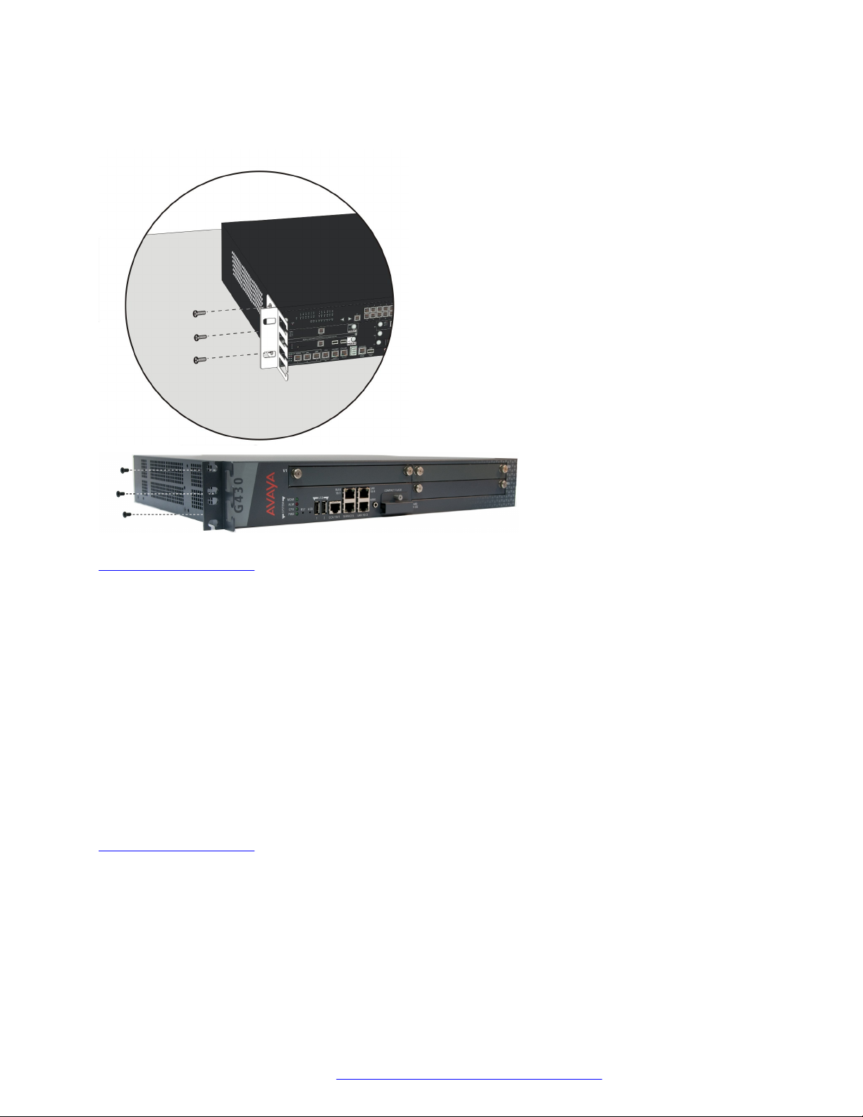
Attaching each mounting bracket to the Branch Gateway
About this task
The Branch Gateway is held in place by mounting screws through the two mounting ears. Fill racks
from the bottom; that is, mount units in the lower positions first, to avoid balancing problems and
cabling complications.
Procedure
1. Position a bracket over the desired mounting position.
2. Affix the bracket to the chassis with three of the nine4-40 flat head screws provided.
3. Tighten with a screwdriver.
Related links
Branch Gateway racks on page 22
Before mounting the Branch Gateway
Procedure
1. Ensure that the rack is bolted to the floor and is earthquake-protected, if required.
If the rack is not securely fixed in place, do not proceed with the installation.
February 2017 Installation and Upgrades for the Avaya Branch Gateway G430 24
Comments on this document? infodev@avaya.com
Page 25

2. If the Branch Gateway is being mounted in a rack with other equipment already installed, the
Branch Gateway must be positioned to avoid imbalance.
Result
Note:
The Branch Gateway weighs under 11 pounds (5 kg) empty and between 13 and 14 pounds
(between 6 and 7 kg) when equipped with media modules. The EM200 weighs under 11 pounds
(5 kg) empty and between 12 and 13 pounds (between 5 and 6 kg) when equipped with media
modules.
Related links
Branch Gateway racks on page 22
Mounting the Branch Gateway in the rack
Procedure
1. Position the Branch Gateway in the rack.
Ensure that there is adequate ventilation.
2. Verify that the screw holes are aligned with the rack hole positions.
Branch Gateway installations
Related links
Branch Gateway racks on page 22
Mounting the Branch Gateway on a wall
About this task
Note:
You can only mount a G430 on a wall if you do not attach any EM200 modules to it.
To mount the Branch Gateway on a wall, use the two wall mounting brackets You can also add a
mounting bracket with cable guides if desired, as explained in
page 23.
Caution:
If you are installing the Branch Gateway in the United States of America:
• The AC power supply cord must not be attached to the building wall, for example with wire
staples, clamps, and so on.
• You must install the Branch Gateway near the AC receptacle (socket outlet) that services
the Branch Gateway.
• You must install the AC power supply cord in a way that minimizes the risk of physical
damage to the cord. The cord must not be hanging on the floor, or routed in any way that
can subject it to physical abuse.
Brackets with cable guides on
Related links
Mounting the Branch Gateway chassis on page 21
Attaching brackets to the Branch Gateway for wall mounting on page 26
February 2017 Installation and Upgrades for the Avaya Branch Gateway G430 25
Comments on this document? infodev@avaya.com
Page 26
Installing the Branch Gateway and EM200
Fastening the Branch Gateway to the wall on page 26
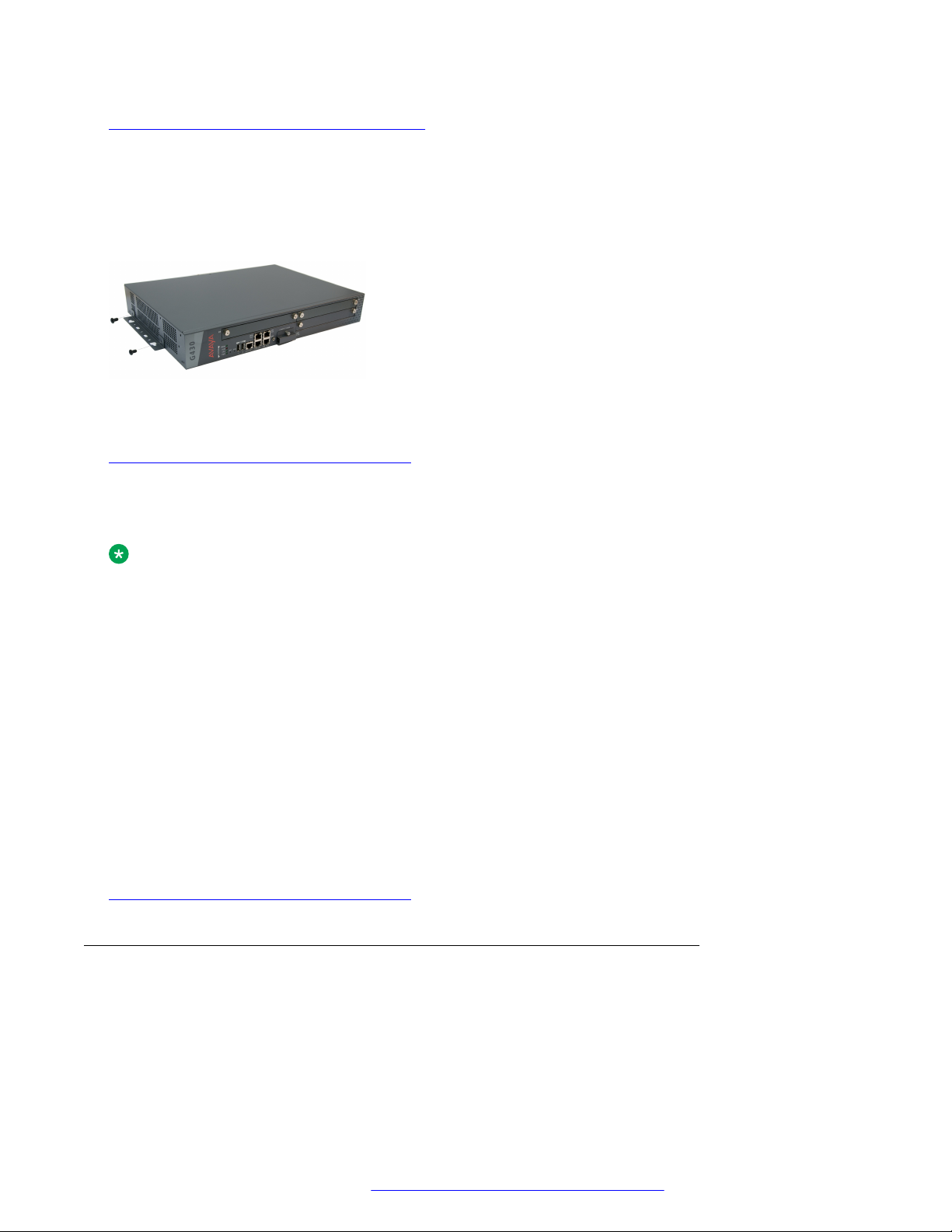
Attaching brackets to the Branch Gateway for wall mounting
About this task
Attach a wall mounting bracket to each side of the Branch Gateway, as shown in the following
figure.
Figure 1: Attaching a bracket to each side of the Branch Gateway
Related links
Mounting the Branch Gateway on a wall on page 25
Fastening the Branch Gateway to the wall
About this task
Note:
The plywood and the hardware to mount the plywood are customer-provided.
Procedure
1. If the wall does not have a portion of plywood available, mount a plywood sheet at least ¾ in
(2.0 cm) thick and at least 4 x 4 ft (1.2 x 1.2 m) in size, horizontally onto the wall.
Make sure the plywood is sufficiently anchored in the wall. Use a minimum of four wood
screws and ensure the screws are driven into wall studs, or use four wall anchors rated not
less than 50 pounds (22.5 kg) shear strength each.
2. Mark the plywood with the location of the Branch Gateway bracket screw holes before
fastening the plywood to the wall.
3. Position the Branch Gateway so that its front panel is facing up, and secure it to the plywood
using a minimum of four screws (pan head at least ¾ in, #10-12 screw).
Related links
Mounting the Branch Gateway on a wall on page 25
Placing the Branch Gateway on a table
About this task
If you install the Branch Gateway as a tabletop unit, affix the provided rubber feet to the underside of
the Branch Gateway.
February 2017 Installation and Upgrades for the Avaya Branch Gateway G430 26
Comments on this document? infodev@avaya.com
Page 27

Mounting the EM200 expansion module(s)
Procedure
1. Remove the four feet from their packaging.
2. Turn the Branch Gateway upside down.
3. Position each foot into one of the mounting sites, near each corner of the chassis.
Related links
Branch Gateway installations on page 21
Mounting the EM200 expansion module(s)
About this task
You can optionally extend the G430 by attaching one or two EM200 expansion modules to the
G430. Since the cables attaching the EM200 expansion modules to the G430 are short, you must
install the Branch Gateway and EM200s directly above or below each other.
The EM200 expansion modules can be mounted in a rack or on a table, similarly to how the Branch
Gateway is mounted. Refer to
although the figures illustrating the mounting instructions depict a Branch Gateway, all rack and
table mounting procedures apply equally to both the G430 and the EM200. Keep in mind the
following:
Mounting the Branch Gateway chassis on page 21. Note that
Procedure
If you are mounting the Branch Gateway and EM200 module(s) on a table, always place the G430
on top of the EM200(s).
This enables easy access in case you need to open the G430 cover in order to add or replace a
DSP module or the RAM card.
Result
Note:
You cannot mount a G430 with EM200 modules on a wall.
Related links
EM200 installation on page 27
EM200 installation
If you mounted one or two EM200 modules for the purpose of expanding the Branch Gateway,
connect each EM200 to the G430 using the expansion cable supplied with each EM200.
• If you mounted one EM200:
1. Connect one end of the expansion cable to the CONNECTOR OUT 1 connector on the
rear of the G430.
February 2017 Installation and Upgrades for the Avaya Branch Gateway G430 27
Comments on this document? infodev@avaya.com
Page 28

Installing the Branch Gateway and EM200
2. Connect the other end of the expansion cable to the CONNECTOR IN connector on the
rear of the EM200.
Figure 2: Connecting an EM200 to the G430
• If you mounted two EM200 modules, connect one EM200 to the CONNECTOR OUT 1
connector on the rear of the G430, and one EM200 to the CONNECTOR OUT 2 connector on
the rear of the G430.
Related links
Mounting the EM200 expansion module(s) on page 27
Installing the media modules
When the Branch Gateway chassis and optionally the EM200 module(s) are installed, you can insert
the media modules. Each module is shipped with two thumb screws for securing the module in the
Branch Gateway or EM200 chassis.
Note:
The required media modules are sometimes pre-installed in the Branch Gateway or EM200
chassis. If this is the case, skip this step. Read this section only if the media modules are not
pre-installed, or if you want to replace modules or add new media modules.
Related links
Before inserting media modules into the Branch Gateway or EM200 chassis on page 28
Combination limitations on page 29
Slot allocation on page 29
Inserting the S8300 Server on page 31
Inserting media modules on page 32
Before inserting media modules into the Branch Gateway or EM200 chassis
• Do not install an unsupported combination of media modules. See Combination limitations on
page 29.
• Allocate a permissible slot to each media module. See
February 2017 Installation and Upgrades for the Avaya Branch Gateway G430 28
Comments on this document? infodev@avaya.com
Allocating slots on page 29.
Page 29

Warning:
Do not operate the Branch Gateway and EM200 with any open slots. Failure to cover empty
slots with the supplied blank plates can cause overheating due to inadequate air distribution.
Related links
Installing the media modules on page 28
Combination limitations
The Branch Gateway chassis is designed to accommodate:
• Up to three of the following telephony media modules: MM710, MM710B, MM711, MM712,
MM714, MM714B, MM720, MM722
• Up to two of the following telephony media modules: MM716, MM717
• Up to one S8300 server, in slot V1 only
Each EM200 chassis is designed to accommodate:
• Up to two of the following telephony media modules: MM710, MM170B, MM711, MM712,
MM714, MM714B, MM716, MM717, MM720, MM722
Installing the media modules
• Up to four MM721 modules
Note:
Although you can insert a total of seven MM710 or MM710B media modules in the extended
G430 (a G430 with two EM200 expansion modules), the optimum number is four MM710 or
MM710B media modules, since the Branch Gateway can support up to 100 VoIP channels.
Related links
Installing the media modules on page 28
Slot allocation
The Branch Gateway chassis has three media module slots, marked V1, V2, and V3the figure on
page 30).Each of the two optional EM200 expansion modules has two media module slots each
the figure on page 111 ). The slots of the EM200 connected to the EXPANSION OUT 1
(see
connector on the rear of the G430 are slots V5 and V6, and the slots of the EM200 connected to the
EXPANSION OUT 2 connector on the rear of the G430 are slots V7 and V8.
lists the permitted slots for each media module.
Allocate a slot for the media module. Make sure your slot allocations allow a permissible slot for
every media module.
Table 1 on page 30
February 2017 Installation and Upgrades for the Avaya Branch Gateway G430 29
Comments on this document? infodev@avaya.com
Page 30
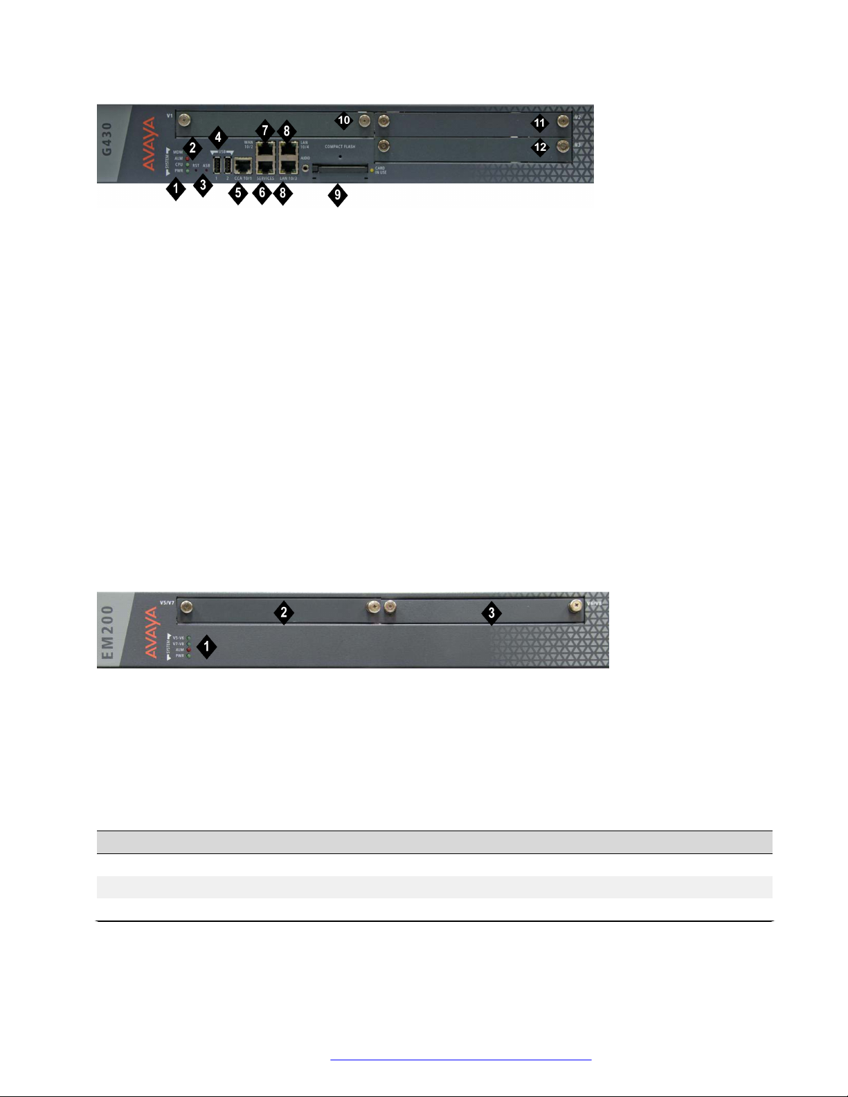
Installing the Branch Gateway and EM200
Figure 3: The G430 Branch Gateway front panel ports and slots
Table 1: Figure notes:
1. System LEDs
2. RST button
3. ASB button
4. USB 2.0 ports
5. CCA (Contact Closure) port
6. 10/100M Services port
7. 10/100M ETH WAN port
8. 10/100M ETH LAN ports
9. Compact Flash slot
10. V1 — slot for media module or S8300 Server
11. V2 — slot for media module
12. V3 — slot for media module
Figure 4: The EM200 front panel slots
Table 2: Figure notes:
1. System LEDs
1. V5/V7 — slot for media module
2. V6/V8 — slot for media module
Table 3: Permitted slots for Branch Gateway and EM200 media modules
Media module
Permitted slots Description
MM710 V1-V3, V5-V8 1 T1/E1 ISDN PRI trunk port
MM710B V1-V3, V5-V8 1 T1/E1 ISDN PRI trunk port
MM711 V1-V3, V5-V8 8 universal analog ports
Table continues…
February 2017 Installation and Upgrades for the Avaya Branch Gateway G430 30
Comments on this document? infodev@avaya.com
Page 31

Installing the media modules
Media module Permitted slots Description
MM712 V1-V3, V5-V8 8 DCP telephone ports
MM714 V1-V3, V5-V8 4 analog telephone ports and 4 analog trunk ports
MM714B V1-V3, V5-V8 4 analog telephone ports, 4 analog trunk ports, and an
emergency transfer relay
MM716 V1-V3, V5-V8 24 analog ports
MM717 V1-V3, V5-V8 24 DCP telephone ports
MM720 V1-V3, V5-V8 8 ISDN BRI trunk or endpoint (telephone or data) ports
MM721 V1-V3, V5-V8 8 ISDN BRI trunk or endpoint (telephone or data) ports
MM722 V1-V3, V5-V8 2 ISDN BRI trunk ports
S8300C or S8300D V1 Communication Manager server
Related links
Installing the media modules on page 28
Inserting the S8300 Server
About this task
You can only install the S8300 in slot V1 on the left side of the Branch Gateway.
Electrostatic alert:
Hold the module only by its edges to avoid damage from static electricity. Do not touch the top
or bottom of the circuit board. If possible, wear a wrist-strap and use an anti-static bag.
Caution:
The connector pins can be bent or damaged if the module is handled roughly, or if misaligned
and then forced into position.
Caution:
Separate ESD paths to the chassis ground connect to the media modules at the spring-loaded
captive screws. Use a screwdriver to ensure the captive screws are securely tightened to
prevent damage to the equipment.
Procedure
1. If you are installing an S8300, remove the plate above slot V1
2. Remove the blank plate from slot V1.
3. Position the server before the V1 bay opening and engage both sides of the module in the
interior guides.
4. Slide the S8300 Server slowly into the chassis, maintaining an even pressure to assure that
the module does not become twisted or disengaged from the guides.
February 2017 Installation and Upgrades for the Avaya Branch Gateway G430 31
Comments on this document? infodev@avaya.com
Page 32

Installing the Branch Gateway and EM200
Figure 5: Inserting the S8300 Server
5. Apply firm pressure to engage the connectors.
The connector has pins of different lengths. The long pins engage first to provide grounding.
Medium length and short pins provide power and signal.
6. Lock the S8300 Server module into the chassis by tightening the spring-loaded captive
screws on the front of the module.
If you are installing an S8300, replace the plate labelled “Remove before removing or
inserting S8300 module” above slot V1
7. After you have inserted the S8300 Server module, if applicable, insert the rest of the media
modules.
Make sure to insert each module in a permissible slot.
Result
Danger:
To prevent access to electrical hazards by unauthorized personnel and to ensure continued
compliance to radiated emissions requirements, all captive screws must be securely tightened
such that they cannot be loosened without the use of a tool.
Related links
Installing the media modules on page 28
Inserting media modules
About this task
After you have inserted the S8300 Server module, if applicable, insert the rest of the media
modules. Make sure to insert each module in a permissible slot. Remove the blank plate from the
empty bay.
Electrostatic alert:
Hold media modules only by the edges to avoid damage from static electricity. Do not touch the
top or bottom of the circuit board. If possible, wear a wrist-strap and use an anti-static bag.
Caution:
The connector pins can be bent or damaged if the module is handled roughly, or if misaligned
and then forced into position.
February 2017 Installation and Upgrades for the Avaya Branch Gateway G430 32
Comments on this document? infodev@avaya.com
Page 33

Ground conductor attachments
Caution:
Separate ESD paths to the chassis ground connect to the media modules at the spring-loaded
captive screws. Use a screwdriver to ensure the captive screws are securely tightened to
prevent damage to the equipment.
Procedure
1. Position the media module before the selected bay on the front of the Branch Gateway or
EM200 chassis and engage both sides of the module in the interior guides.
2. Slide the module slowly into the chassis, maintaining an even pressure to assure that the
module does not become twisted or disengaged from the guides.
Figure 6: Inserting a media module
3. Apply firm pressure to engage the connectors.
The media module connector has pins of different lengths. The long pins engage first to
provide grounding. Medium length and short pins provide power and signal.
4. Lock the media module into the chassis by tightening the spring-loaded captive screws on
the front of the module.
Result
Danger:
To prevent access to electrical hazards by unauthorized personnel and to ensure continued
compliance to international radiated emissions requirements, all captive screws must be
securely tightened such that they cannot be loosened without the use of a tool.
Warning:
After you have connected telephones to the various media modules, be sure to add circuit
protection to the lines.
Related links
Installing the media modules on page 28
Ground conductor attachments
To assure safe installation and operation, carefully read all requirements, recommendations, and
instructions. Pay special attention to all CAUTION, WARNING, and DANGER statements.
February 2017 Installation and Upgrades for the Avaya Branch Gateway G430 33
Comments on this document? infodev@avaya.com
Page 34

Installing the Branch Gateway and EM200
Warning:
System grounding must comply with the general rules for grounding provided in Article 250 of
the National Electrical Code (NEC), National Fire Protection Agency (NFPA) 70, or the
applicable electrical code in the country of installation.
Related links
General grounding requirements on page 34
Approved grounds on page 36
Safety ground connections on page 39
Connecting power to the EM200 expansion modules on page 41
Connecting power to the Branch Gateway on page 42
General grounding requirements
Note:
Grounding requirements differ widely from country to country. In addition to the grounding
instructions presented in this section, you must follow the local electrical installation codes for
your location.
Two safety grounds are required to ensure safe operation of each Branch Gateway and each
EM200: the ground conductor that is part of the AC power cord, and the field-installed green/yellow
conductor referred to as the Supplementary Ground Conductor. Both safety grounds must be
connected to an approved ground. If a power cord accompanies the Branch Gateway or EM200,
use that cord whenever possible.
Related links
Ground conductor attachments on page 33
Installation location on page 34
Ground conductor on page 35
Ground block on page 35
Restricted Access Location on page 35
Installation location
Select a location for the Branch Gateway or EM200 installation that is close enough for use with the
supplied secondary grounding conductor. If this location requirement is not met, contact a licensed
electrician to install a Supplementary Ground Conductor per Article 250 of the National Electrical
Code (NEC).
Warning:
If the installation location is greater than the length of the supplied secondary grounding
conductor from an approved ground, do not install the Branch Gateway or EM200 until a
licensed electrician is present to install a Supplementary Ground Conductor.
February 2017 Installation and Upgrades for the Avaya Branch Gateway G430 34
Comments on this document? infodev@avaya.com
Page 35

Ground conductor attachments
Related links
General grounding requirements on page 34
Ground conductor
A Supplementary Ground Conductor is provided with the equipment, and is constructed of 10 AWG
(4.0 mm2) wire, with an insulated ring terminal crimped to one end that is suitable for the #8 (M4)
stud/screw on the rear of the Branch Gateway or EM200 chassis.
The customer will need to provide a means of connecting this Supplementary Ground Conductor to
an approved ground according to Article 250 of the National Electrical Code (NEC).
Related links
General grounding requirements on page 34
Ground block
A ground block, supplied by the customer and installed by an electrician, is available for use when
you are installing multiple Branch Gateways or EM200s . The ground block, intended for rack
mounting, has ten terminals available for terminating Supplementary Ground Conductors. Up to ten
Branch Gateways or EM200s can be grounded at the block installed close to the equipment (on a
rack) and then a single ground conductor can be routed from the same block to an approved
ground.
Danger:
Failure to install both grounds will void the Product Safety certifications (UL and the CE Mark)
on the product, as well as allow a hazard to be present that could result in death or severe
personal injury.
Related links
General grounding requirements on page 34
Restricted Access Location
In Finland, Norway, and Sweden, the Branch Gateway and EM200s must be installed in a
Restricted Access Location, due to unreliable earthing concerns. A Restricted Access Location is
defined as access that can be gained by only Service Personnel or Customers who have been
instructed about the reasons for the restricted access and any safety precautions that must be
taken. In these cases, access to the Branch Gateway or EM200s is gained by the use of a tool
(such as a lock and key) or other means of security.
Warning:
For installations in Finland, Norway, and Sweden, the Branch Gateway and EM200 rely on two
ground connections (mains plug with an earth contact, and a Supplementary Ground
Conductor).
Related links
General grounding requirements on page 34
February 2017 Installation and Upgrades for the Avaya Branch Gateway G430 35
Comments on this document? infodev@avaya.com
Page 36

Installing the Branch Gateway and EM200
Approved grounds
There are two methods for equipment grounding.
The first is based on NFPA 70: National Electrical Code (NEC – a United States code).
Note:
Compliance with NFPA 70: NEC – or – with the equivalent local electrical code/grounding
requirements is mandatory.
The second is based on ANSI/EIA/TIA-607 (Commercial Building Grounding (Earthing) and Bonding
Requirements for Telecommunications).
Note:
ANSI/EIA/TIA-607 (TIA-607) defines an intra-building ground-wiring scheme for communications
equipment, and specifies equipment connection/grounding points according to that scheme.
TIA-607 assumes the underlying building grounding infrastructure is in compliance with NFPA
70: NEC. Compliance with the NEC (or the equivalent local electrical code/grounding
requirements) is essential for the proper application of TIA-607.
Compliance with NFPA 70: NEC will provide suitable grounding for the Avaya equipment. TIA-607
provides an enhanced, communications-specific grounding scheme: where TIA-607 has been
implemented the Avaya equipment shall be grounded per this method.
Important:
• Ensure that the installation site has access to approved grounds and that either a trained
technician or a licensed electrician will be verifying all grounds and installing the
Supplementary Ground Conductor.
• If you have difficulty interpreting the grounding methods in this document, Avaya
recommends obtaining the services of a certified power contractor or auditor prior to
system installation or cutover.
Warning:
Failure to follow grounding recommendations can result is a system installation that is:
• Unsafe for personnel handling or using the equipment
• Not properly protected from lightning or power transients
• Subject to service interruptions
NFPA 70: NEC
In buildings without a ground-cabling infrastructure meeting TIA-607 the Avaya equipment shall be
grounded by connection to the nearest accessible location on one of the following approved building
grounds:
Note:
The following are approved grounds in keeping with the NFPA 70: National Electrical Code of
the United States (NEC). For additional information regarding these grounds consult the NEC,
Article 250.52.
February 2017 Installation and Upgrades for the Avaya Branch Gateway G430 36
Comments on this document? infodev@avaya.com
Page 37

Ground conductor attachments
AC Service Panel:
• AC ground at the AC service panel serving the Avaya equipment.
Danger:
• Do not perform work inside electrical panels unless you are a qualified electrician.
• Do not try to remove bonding conductors without approval from qualified personnel.
Metal Water Pipe:
The water pipe must meet all the following –
• The entire length of the pipe must be visible – except for short sections passing through walls,
ceilings, etc.
• Be metallic thorough its length, or made electrically continuous by bonding around insulation
joints or insulating pipe.
• Be routed underground for at least 3 meters (10 feet).
Where a metal water pipe is used as an approved ground the following requirements apply to the
host building:
• The building must be industrial, commercial, or institutional, where only qualified persons
service the water piping.
• The building shall not rely only on the metal water pipe for grounding: a supplemental ground is
required. (See NEC Article 250.53 for additional details.)
Metal Frame of the Building:
The metal frame member (I-beam, pillar) must be connected to earth by one of the following
methods –
• Be in direct contact with the earth, or encased in concrete that is in direct contact with the
earth, for at least 3 meters (10 feet).
• Be connected to the reinforcing bars of a concrete-encased electrode. The electrode must be
encased by at least 5.1 cm (2 inches) of concrete and located within and near the bottom of a
concrete foundation or footing in direct contact with the earth. The electrode must be at least
6.1 meters (20 feet) of one or more steel reinforcing bars or rods, 1.3 cm (0.5 inches) in
diameter, or at least 6.1 meters (20 feet) of bare solid copper, 4 AWG (26mm2) wire.
• Be connected to a ground ring. A ground ring is a buried ground that encircles a building,
having a length of at least 6.1 meters (20 feet) of 2 AWG (35mm2) bare copper wire.
• Be connected to rod and pipe electrodes. A rod or pipe electrode consists of one 1.6 cm (5/8
inch) solid rod or 2 cm (3/5 inch) conduit driven to a minimum depth of 2.4 meters (8 feet).
• Be connected to plate electrodes. Plate electrodes have a minimum of 0.185 square meter (2
square feet) of metallic surface exposed to the exterior soil.
Approved floor grounds:
Floor grounds are those grounds on each floor of a high-rise building that are suitable for connection
to the ground terminal in the riser closet and to the equipment single-point ground terminal.
Approved floor grounds may include the following:
• Metal Frame of the Building (in accordance with the criteria specified in
Metal Frame of the
Building on page 37)
February 2017 Installation and Upgrades for the Avaya Branch Gateway G430 37
Comments on this document? infodev@avaya.com
Page 38

Installing the Branch Gateway and EM200
• The grounding conductor for the secondary side of the power transformer feeding the floor
• A grounding point specifically provided in the building for that purpose
Warning:
If the approved ground or approved floor ground can only be accessed inside a dedicated power
equipment room, then connections to the ground must be made by a licensed electrician.
ANSI/EIA/TIA-607:
In buildings where a ground-cabling infrastructure meeting TIA-607 has been implemented the
Avaya equipment shall be grounded according to the TIA-607 standard. In a TIA-607 installation, the
Telecommunications Main Grounding Busbar (TMGB)/Telecommunications Grounding Busbar
(TGB) links the telecommunications equipment to the ground.
Other grounding terminology is:
• Building principle ground, normally in a building with one floor.
• Floor ground bar, normally in buildings with more than one floor.
Refer to
Figure 7: ANSI/TIA/EIA-607 Grounding Schematic on page 38.
Configure telecommunications subsystems, such as groups of frames or equipment, as separate
single-point ground entities connected to the equipment’s dedicated service panel via a single-point
ground bar. The service panel ground connects to the building principle ground via the main service
panel or, in a TIA-607 installation, via the TGB. Refer to
Figure 8: Typical Wiring Plan on page 39.
Figure 7: ANSI/TIA/EIA-607 Grounding Schematic
February 2017 Installation and Upgrades for the Avaya Branch Gateway G430 38
Comments on this document? infodev@avaya.com
Page 39

Ground conductor attachments
Figure 8: Typical Wiring Plan
Related links
Ground conductor attachments on page 33
Safety ground connections
Proper grounding of the Branch Gateway installation safeguards the system, users, and service
personnel by providing protection from lightning, power surges, AC mains faults, power crosses on
central office trunks, and electrostatic discharge (ESD).
Local electrical installation codes must be followed when installing the Branch Gateway.
Proper grounding of the Branch Gateway and EM200s installation safeguards the system, users,
and service personnel by providing protection from lightning, power surges, AC mains faults, power
crosses on central office trunks, and electrostatic discharge (ESD).
Local electrical installation codes must be followed when installing the Branch Gateway or EM200.
Danger:
Connection of both grounds (through the AC Power Cord and the Supplementary Ground
Conductor) is required for safe operation of the Branch Gateway.
Connection of both grounds (through the AC Power Cord and the Supplementary Ground
Conductor) is required for safe operation of the Branch Gateway or EM200.
February 2017 Installation and Upgrades for the Avaya Branch Gateway G430 39
Comments on this document? infodev@avaya.com
Page 40

Installing the Branch Gateway and EM200
Warning:
An improper ground can cause electrical shock as well as equipment failures and service
outages.
Related links
Ground conductor attachments on page 33
Attaching the ground wires on page 40
Attaching the ground wires
About this task
Perform the following in each Branch Gateway and EM200.
Procedure
1. Unscrew the lock nut of the ground screw on the rear of the chassis adjacent to the ground
symbol.
2. Place the ring terminal of the 10 AWG (4.0 mm2) Supplementary Ground Conductor on the
ground screw.
3. Tightly close the lock nut.
Related links
Safety ground connections on page 39
Attaching ground wires for purchased ground blocks on page 40
Attaching ground wires for unused ground blocks on page 41
Attaching ground wires for purchased ground blocks
Procedure
1. Cut the Supplementary Ground Conductor (which has one end attached to the grounding
screw on the chassis) to the length needed to terminate it into one of the terminals of the
ground block.
Do not coil the Supplementary Ground Conductor.
2. Attach one end of the remaining 10 AWG (4 mm2) ground wire to one of the terminals in the
ground block and the other end to an approved ground.
3. Cut this ground wire to the length needed to reach the approved ground.
Do not coil this wire.
Result
Note:
The ground block is for use with more than one Branch Gateway or EM200 in the rack. If the
ground block is to be used, you must supply it and have it installed by an electrician.
Related links
Attaching the ground wires on page 40
February 2017 Installation and Upgrades for the Avaya Branch Gateway G430 40
Comments on this document? infodev@avaya.com
Page 41

Ground conductor attachments
Attaching ground wires for unused ground blocks
Procedure
1. Attach the Supplementary Ground Conductor to an approved ground.
2. Connect the AC power cable to the inlet receptacle on the rear of the chassis.
Result
Note:
If two PSUs are installed in the Branch Gateway, the PWR LED blinks if only one PSU is
connected to power, and stays on if both PSUs are connected to power.
Related links
Attaching the ground wires on page 40
Connecting power to the EM200 expansion modules
About this task
Warning:
Connect power to the EM200 expansion modules before you connect power to the G430.
Failure to do so may cause unexpected results.
For each EM200 module you connected to the G430:
Procedure
1. Connect the power cable to the power connector on the EM200 back panel.
2. Plug the power cable into a mains socket.
The EM200 is now powered.
The V5-V6 LED on the EM200 front panel lights if the EM200 is connected to the
CONNECTOR OUT 1 connector on the rear panel of the G430. This indicates that the two
media module slots are considered slot 5 and slot 6 of the G430.
The V7-V8 LED on the EM200 front panel lights if the EM200 is connected to the
CONNECTOR OUT 2 connector on the rear panel of the G430. This indicates that the two
media module slots are considered slot 7 and slot 8 of the G430.
The PWR LED on the front panel lights, indicating the EM200 is powered.
Result
Warning:
If you wish to move an EM200 in a working system consisting of a G430 and one or two
EM200s housing media modules, you must disconnect the EM200 from power before
reconnecting the expansion cable to the new location. Failure to do so may cause unexpected
results.
February 2017 Installation and Upgrades for the Avaya Branch Gateway G430 41
Comments on this document? infodev@avaya.com
Page 42

Installing the Branch Gateway and EM200
Related links
Ground conductor attachments on page 33
Connecting power to the Branch Gateway
About this task
After you have mounted the Branch Gateway, optionally mounted and connected EM200 device(s),
installed the media modules, and attached grounding conductors, you can connect power to the
Branch Gateway.
Procedure
1. Connect the power cable to the power connector on the Branch Gateway back panel.
2. Plug the power cable into an AC outlet.
The Branch Gateway is now powered.
The PWR LED on the front panel lights. The CPU LED lights up if the firmware is running. At
least one LED on each media module, except the S8300, lights up initially and then goes off
after about 20 seconds.
Related links
Ground conductor attachments on page 33
February 2017 Installation and Upgrades for the Avaya Branch Gateway G430 42
Comments on this document? infodev@avaya.com
Page 43

Chapter 3: Connecting devices
Connecting devices
External endpoint devices can be connected to the ports on the front panels of the installed media
modules and to the fixed front panel ports. Before you connect endpoint devices, the Branch
Gateway, and EM200s if desired, should be mounted and all media modules should be inserted.
Warning:
To reduce the risk of fire, use only 26 AWG or larger telecommunication line cords when
installing telephones or adjuncts, or connecting to any media module telecommunication ports.
Related links
Roadmap for connecting devices on page 43
Data and voice device connections on page 44
Circuit protection installation on page 52
Connecting an E1/T1 WAN link to the MM340 media module on page 53
Coupled Bonding Conductor installations on page 54
Avaya Partner Contact Closure Adjunct installations on page 54
Roadmap for connecting devices
Connect these devices in the following order using the appropriate procedure described in this
section:
1. Data and voice devices
2. Circuit protection
3. Wide Area Network (WAN)
4. Coupled Bonding Conductor (CBC)
5. Avaya Partner Contact Closure Adjunct
Related links
Connecting devices on page 43
February 2017 Installation and Upgrades for the Avaya Branch Gateway G430 43
Comments on this document? infodev@avaya.com
Page 44

Connecting devices
Data and voice device connections
There are various possible ways of connecting different devices. See your planning documentation
for any topology requirements to connect specific devices to specific ports. As you connect devices,
keep a record of the slots and ports into which specific devices are connected. You will need this
information when configuring the Branch Gateway.
Related links
Connecting devices on page 43
Switch or network data port connections on page 44
IP telephone connections on page 44
ISDN BRI station connections on page 45
Connecting an analog telephone on page 46
Connecting a DCP telephone to an MM712 or MM717 media module on page 48
Connecting an analog trunk on page 49
Connecting an analog DID trunk on page 49
Connecting an E1/T1 trunk on page 49
Connecting an ISDN BRI trunk on page 50
Connecting devices to the MM717 and MM716 media modules on page 50
Switch or network data port connections
You can connect one or more LAN switches to either of the ETH LAN ports on the front panel.
Related links
Data and voice device connections on page 44
IP telephone connections
Note:
For a full list of supported phones, see Appendix B, Supported Avaya telephones in Overview
for the Avaya G430.
Connect the IP telephone to an external Ethernet switch that has connectivity with the Avaya Branch
Gateway G430. The IP phone can powered either by the switch or by its own power supply.
Related links
Data and voice device connections on page 44
Connecting the telephone to the Branch Gateway on page 44
Connecting the telephone to the Branch Gateway
Procedure
1. Wire a telephone to a port on the switch connected to the Branch Gateway LAN port.
February 2017 Installation and Upgrades for the Avaya Branch Gateway G430 44
Comments on this document? infodev@avaya.com
Page 45

Connecting devices
If the switch is a PoE switch, you do not need to plug the IP telephone into a power supply.
2. Plug the telephone into the telephone port.
3. If the IP telephone is powered independently, plug the IP telephone into a power supply.
Check that the IP telephone is powered up.
Related links
IP telephone connections on page 44
ISDN BRI station connections
Each ISDN port on the MM720 or MM721 media module supports up to two ISDN BRI stations.
Note:
The MM720 and MM721 BRI media modules cannot be administered to support both BRI trunks
and BRI stations at the same time. However, the MM720 and MM721 BRI media modules
support combining both B-channels together to form a 128-kbps channel. Communication
Manager 3.1 enables combining B-channels, using BONDing, to form a higher bandwidth
connection. Finally, if the MM720 or MM721 BRI media module is administered to support BRI
stations, it cannot be used as a clock synchronization source.
Related links
Data and voice device connections on page 44
Connecting one ISDN BRI station to one ISDN port on page 45
Connecting two ISDN BRI stations to one ISDN port on page 45
Connecting one ISDN BRI station to one ISDN port
Procedure
Connect the station via a standard 8-pin BRI cable to one of the ISDN ports on an MM720 media
module.
Related links
ISDN BRI station connections on page 45
Connecting two ISDN BRI stations to one ISDN port
Procedure
1. Connect each station to an RJ-45 splitter that provides two RJ-45 4-pair jacks, and one
RJ-45 male connector.
See
the figure on page 46 for the correct wiring for the splitter.
2. Connect the male connector of the splitter to one of the ISDN ports on an MM720 or MM721
media module.
February 2017 Installation and Upgrades for the Avaya Branch Gateway G430 45
Comments on this document? infodev@avaya.com
Page 46

Connecting devices
Figure 9: RJ-45 splitter wiring for connecting two ISDN BRI stations to one ISDN port
Figure 10: The MM720 media module
Figure 11: The MM721 media module
Related links
ISDN BRI station connections on page 45
Connecting an analog telephone
About this task
Note:
For a full list of supported phones, see Appendix B, Supported Avaya telephones in Overview
for the Avaya Branch Gateway G430..
February 2017 Installation and Upgrades for the Avaya Branch Gateway G430 46
Comments on this document? infodev@avaya.com
Page 47

Procedure
1. Wire a telephone port to one of the following analog ports:
• A universal analog port on an MM711 media module
• Any analog line port on a punch down block connected to an MM716 media module. To
connect the MM716 media module to a punch down block to enable telephone
connection, see
Connecting devices to the MM717 and MM716 media modules on
page 50.
• A LINE port on an MM714 or MM714B media module
2. Plug the analog telephone into the telephone port.
Result
Figure 12: The MM711 media module
Connecting devices
Figure 13: The MM714 media module
Figure 14: The MM714B media module
Figure 15: The MM716 media module
Note:
Analog line ports support the following maximum distances:
For phone equipment with a ringer load below 3 REN: up to 2,000 feet (609.6 m).
Related links
Data and voice device connections on page 44
February 2017 Installation and Upgrades for the Avaya Branch Gateway G430 47
Comments on this document? infodev@avaya.com
Page 48

Connecting devices
Connecting a DCP telephone to an MM712 or MM717 media module
About this task
Note:
For a full list of supported phones, see Appendix B, Supported Avaya telephones in Overview
for the Avaya Branch Gateway G430..
Warning:
Avaya MM712 and MM717 DCP Lines. DCP lines require the 146E IROB (In-range, Out of
Building) protectors, or the 4C3S-75 solid-state 5-pin protectors, when they are used for any
connection routed out-of-building. These protection devices provide both overvoltage and
overcurrent protection.
Procedure
Wire a telephone port to a DCP port on the Branch Gateway.
The following media modules provide DCP telephone ports:
• MM712. Eight DCP ports
• MM717. Twenty four DCP ports, provided via a single 25-pair amphenol socket on the front
panel. To connect the MM717 media module to a punch down block to enable telephone
connection, see Connecting devices to the MM717 and MM716 media modules on page 50.
Figure 16: The MM312 media module
Figure 17: .The MM712 media module
Figure 18: .The MM717 media module
Related links
Data and voice device connections on page 44
February 2017 Installation and Upgrades for the Avaya Branch Gateway G430 48
Comments on this document? infodev@avaya.com
Page 49

Connecting an analog trunk
Procedure
Connect the trunk to one of the following ports:
• Any universal analog port on an MM711 media module
• One of the ports marked TRUNK on an MM714 or MM714B media module
Related links
Data and voice device connections on page 44
Connecting an analog DID trunk
Procedure
Connect the trunk to one of the following ports
• Any universal analog port on an MM711 media module
• Any analog line port on a punch down block connected to an MM716 media module.
To connect the MM716 media module to a punch down block to enable trunk connection,
Connecting devices to the MM717 and MM716 media modules on page 50.
Connecting devices
• One of the ports marked Line on an MM714 or MM714B media module
• The TRUNK port on the Branch Gateway front panel.
Note:
The TRUNK analog telephone port on the Branch Gateway front panel forms a mechanical
analog relay with the LINE port next to it. See
configured to provide emergency transferred telephone service in the case of a power outage
or disconnection from an external server. During an emergency situation, all incoming calls
on the trunk are directed to the telephone plugged into the LINE port. Conversely, the
telephone plugged into the LINE port can use the trunk during an emergency situation to
make outgoing calls.
Related links
Data and voice device connections on page 44
the figure on page 29. This relay can be
Connecting an E1/T1 trunk
About this task
Connect the trunk cable to the E1/T1 port on an MM710 or MM710B media module. The SIG LED
lights.
Figure 19: The MM710B media module
February 2017 Installation and Upgrades for the Avaya Branch Gateway G430 49
Comments on this document? infodev@avaya.com
Page 50

Connecting devices
Related links
Data and voice device connections on page 44
Connecting an ISDN BRI trunk
About this task
Connect the trunk to any ISDN port on an MM720, MM721 or MM722 media module.
Note:
In the US, you need to connect a separately purchased NT1 device to each ISDN port you use
to connect an ISDN BRI trunk.
Figure 20: The MM720 media module
Figure 21: The MM721 media module
Figure 22: The MM722 media module
Related links
Data and voice device connections on page 44
Connecting devices to the MM717 and MM716 media modules
About this task
The MM716 and MM717 media modules each have a single 25-pair amphenol socket on the front
panel, intended for use with a punch down block.
Procedure
Connect the front panel connector to a punch down block.
You can terminate up to 24 endpoint devices on the connected punch down block.
February 2017 Installation and Upgrades for the Avaya Branch Gateway G430 50
Comments on this document? infodev@avaya.com
Page 51

Connecting devices
Related links
Data and voice device connections on page 44
Connecting the MM716 or MM717 front panel connector to a punch down block on page 51
Connecting the MM716 or MM717 front panel connector to a punch down block
Procedure
1. Connect one end of a CAT5 cable with a 25-pair amphenol connector at each end to the 25pair socket on the MM716 or MM717 front panel, so that the cable extends to the right of the
Branch Gateway.
The cable you use must be such that the connector you plug into the media module is 90˚ to
the cable.
2. Tighten the end screw of the amphenol connector to securely fasten the connector to the left
side of the front panel socket.
3. Thread a tie wrap through the small bracket to the right of the front panel socket.
4. Fasten the tie wrap around the cable to secure the cable to the right side of the front panel
socket.
Figure 23: Attaching and securing the amphenol cable to the MM716 or MM717 25-pair socket
5. Connect the other end of the amphenol cable to a punch down block that converts the single
amphenol connector to 24 RJ-11 jacks, as needed.
February 2017 Installation and Upgrades for the Avaya Branch Gateway G430 51
Comments on this document? infodev@avaya.com
Page 52

Connecting devices
Result
You can now connect endpoint devices to the RJ-11 jacks. For the pin-out of the 25-pair connector,
see the table on page 121.
Related links
Connecting devices to the MM717 and MM716 media modules on page 50
Circuit protection installation
Protection from over-voltages (lightning, power line induction and so forth) and over-currents (sneak
currents) is required for ALL off-premises (out-of-building) trunks, lines, and terminal installations.
Campus installations (interbuilding cabling) of telephones or other standard (tip / ring) devices
require over-voltage and sneak current protection in both buildings.
Over-voltage and sneak current protectors must be Listed devices, and installed in accordance with
NFPA 70: NEC Article 800 (subsections “Protective Devices” and “Cable and Primary Protector
Bonding and Grounding”), or must comply with local safety codes.
Field installed sneak current protectors must have a maximum current rating of 350mA and a
minimum voltage rating of 600V.
The following over-voltage and sneak current protection devices have been approved for use with
the G430 Gateway:
• For the Avaya MM710, MM710B media modules: Over-voltage and sneak current protection for
these interfaces are provided on the media modules themselves.
• For the Avaya MM711, MM714, MM714B, and MM716 Analog media modules: Over-voltage
and sneak current protection for these interfaces is provided on the media modules
themselves.
Note:
Incoming trunks normally have primary over-voltage protection provided by the local
telephone company.
Analog voice terminals require one of the following types of combined over-voltage and sneak
current protection at both building entry points:
- Gas tube with heat coil. 4B1E-W
- Solid state with heat coil. 4C1S
- IROB. 146C (4 - lines) or 146H (25 - lines)
• For the Avaya MM712 and MM717 DCP media modules: out-of-building connections require
either the 146E IROB (In-Range Out-of-Building) or 4C3S-75 solid state protectors for overvoltage and sneak current.
• For the Avaya MM722 ISDN-BRI media modules: over-voltage and sneak current protection
are provided on the media modules themselves.
• For the Avaya MM720 and MM721 ISDN-BRI media modules: All out-of-building installations
(both trunk (network) side and line (customer) side) require either the 146E IROB (In-Range
February 2017 Installation and Upgrades for the Avaya Branch Gateway G430 52
Comments on this document? infodev@avaya.com
Page 53

Connecting devices
Out-of-Building) or 4C3S-75 solid state protectors for over-voltage and sneak current. Trunk
(network) side applications also require an NT-1 device.
Warning:
Only service-trained personnel are to install these circuit protection devices.
Related links
Connecting devices on page 43
Connecting an E1/T1 WAN link to the MM340 media module
About this task
Procedure
Plug the WAN line into the E1/T1 port, marked E1/T1, on the MM340 media module
Use an unshielded twisted pair cable, straight or crossover, depending on the WAN equipment.
Related links
Connecting devices on page 43
Connecting an Ethernet WAN link on page 53
Connecting an external router to the Branch Gateway on page 53
Connecting an Ethernet WAN link
About this task
You must connect the Ethernet WAN line (DSL, firewall, etc.) to the Ethernet WAN port on the front
panel of the Branch Gateway chassis. This port is marked ETH WAN. Use a CAT5 Ethernet cable to
connect the WAN line to the port.
Related links
Connecting an E1/T1 WAN link to the MM340 media module on page 53
Connecting an external router to the Branch Gateway
About this task
Procedure
You can connect a router to any of the following ports on the Branch Gateway:
• The ETH WAN ports on the Branch Gateway front panel
• The ETH LAN ports on the Branch Gateway front panel
Related links
Connecting an E1/T1 WAN link to the MM340 media module on page 53
February 2017 Installation and Upgrades for the Avaya Branch Gateway G430 53
Comments on this document? infodev@avaya.com
Page 54

Connecting devices
Coupled Bonding Conductor installations
The Coupled Bonding Conductor (CBC) provides mutual inductance coupling between the CBC and
the telephone cables that are exposed to lightning. The conductor can be a 10 AWG (4 mm2) wire
tie wrapped to the exposed cables, a metal cable shield around the exposed cables, or six spare
pairs from the exposed cable. In a high-rise building, connect the CBC to an approved building
ground on each floor.
Related links
Connecting devices on page 43
Installing the CBC on page 54
Installing the CBC
About this task
Before you begin, be sure the telephone lines are cross-connected to the appropriate media
module(s).
Procedure
1. Connect one end of the conductor to a telephone cable building entrance protector ground
that is connected to an approved ground.
2. Route the rest of the conductor next to the exposed telephone cables being protected until
they reach the cross-connect nearest to the telephone system.
3. Terminate the other end to the single-point ground block provided for the telephone system.
Result
Note:
Position the non-exposed telephone cables at least 12 in (30.5 cm) away from exposed
telephone cables whenever possible.
Related links
Coupled Bonding Conductor installations on page 54
Avaya Partner Contact Closure Adjunct installations
The Contact Closure feature is a controllable relay providing dry contacts for various applications.
To implement the contact closure feature, you connect an Avaya Partner Contact Closure Adjunct
box to the CCA port on the Branch Gateway chassis. The adjunct box provides two contact closures
that can be operated in either a “normally closed” or “normally open” state. The contact closures can
control auxiliary devices such as devices that automatically lock or unlock doors or voice recording
units. The CCA port can be configured so that the connected devices can be controlled by an end
device, such as a telephone. For example, a user can unlock a door by keying a sequence into a
telephone keypad.
February 2017 Installation and Upgrades for the Avaya Branch Gateway G430 54
Comments on this document? infodev@avaya.com
Page 55

Related links
Connecting devices on page 43
Installing the contact closure on page 55
Installing the contact closure
Procedure
1. Follow the installation instructions in the Avaya Partner Contact Closure Adjunct Installation
Instructions leaflet to install the Contact Closure and connect the auxiliary devices that will
be activated and deactivated by the Contact Closure relays.
2. Note which device is connected to each relay.
You will need this information for configuration.
3. Connect the Avaya Partner Contact Closure adjunct box to the CC port on the Branch
Gateway front panel.
Use a 24 gauge minimum telephone wire, no longer than 200 ft, with a standard four wire
RJ-11 connector.
Related links
Avaya Partner Contact Closure Adjunct installations on page 54
Connecting devices
February 2017 Installation and Upgrades for the Avaya Branch Gateway G430 55
Comments on this document? infodev@avaya.com
Page 56

Chapter 4: Connecting and enabling a USB
modem for remote access
Connecting and enabling a USB modem for remote access
About this task
You can connect a USB modem to the Branch Gateway to enable configuration from a remote
location.
If an S8300 is installed in the Branch Gateway, leave a modem connected permanently to enable
reporting of alarms to remote locations.
Related links
Gateways without S8300 modem connections on page 56
Gateways without S8300 modem connections
You can connect a USB modem to the USB port on the Gateway front panel.
Related links
Connecting and enabling a USB modem for remote access on page 56
Branch Gateways with S8300 USB modems
You can connect a USB modem to a USB port on the S8300 front panel. See USB modems
supported by the S8300 on page 130 for a list of the USB modems supported by the S8300.
Related links
Maintenance web pages on page 57
Branch Gateways with S8300 modem connections on page 58
Testing the modem connection (Branch Gateway with S8300) on page 58
Connecting the USB CD-ROM drive on page 59
February 2017 Installation and Upgrades for the Avaya Branch Gateway G430 56
Comments on this document? infodev@avaya.com
Page 57

Branch Gateways with S8300 USB modems
Maintenance web pages
Most of the preparations you are making require you to access the Maintenance web pages part of
Avaya Integrated Management (Avaya IM) from your laptop. After accessing the Maintenance web
pages, leave the Maintenance web pages open until you have completed all the preparations.
Related links
Branch Gateways with S8300 USB modems on page 56
Changing the modem settings on the Configure Server Maintenance Web Page on page 57
Changing the modem settings on the Configure Server Maintenance Web Page
Procedure
1. Select Configure Server from the left-hand menu on the Maintenance web page.
The Back Up Data page appears.
2. Follow the on-screen instructions to back up the current data.
3. Click Continue.
4. Select Configure individual services.
5. Click Continue.
6. From the left navigation menu, click Set Modem Interface.
The Set Modem Interface page appears.
7. Enter the RAS IP address you obtained using the ART tool.
See Running the Automatic Registration Tool (ART) for the RAS IP address on page 13.
8. Click Change modem settings.
9. Click Continue.
10. Click Close Window.
Result
Note:
You can only change the modem settings on the Configure Server Maintenance Web Pages if
you have an Avaya Maintenance contract.
Related links
Maintenance web pages on page 57
February 2017 Installation and Upgrades for the Avaya Branch Gateway G430 57
Comments on this document? infodev@avaya.com
Page 58

Connecting and enabling a USB modem for remote access
Branch Gateways with S8300 modem connections
If your installation includes an S8300 Server module, you must connect the USB modem to the
S8300. After the Branch Gateway is configured, you can leave the modem permanently connected
to enable the S8300 to report alarms to remote locations.
Note:
If you require a USB CD-ROM drive to download software upgrades, connect the USB CD-ROM
drive to the remaining available USB port on the S8300 Server.
Related links
Branch Gateways with S8300 USB modems on page 56
Connecting and enabling the modem on page 58
Connecting and enabling the modem
Procedure
1. Connect the USB modem to a working telephone line.
2. Connect the modem to one of the USB ports on the S8300 Server.
3. From the navigation menu of the Maintenance Web Pages, select Security > Modem.
The Modem page displays.
4. Select Enable modem for unlimited incoming calls.
5. Click Submit.
Related links
Branch Gateways with S8300 modem connections on page 58
Testing the modem connection (Branch Gateway with S8300)
Procedure
1. Setup a dialup connection on a remote PC with the following settings:
• Automatically detect settings.
• No Username, Password, or Domain.
• Security > Show Terminal Window.
2. Dial in to the modem from the remote PC.
3. When prompted, provide the rasaccess login and password in the Terminal Window.
4. Close the Terminal Window to complete the connection.
5. Activate an SSH session.
6. Login valid authentication to the Linux CLI.
February 2017 Installation and Upgrades for the Avaya Branch Gateway G430 58
Comments on this document? infodev@avaya.com
Page 59

Branch Gateways with S8300 USB modems
Related links
Branch Gateways with S8300 USB modems on page 56
Connecting the USB CD-ROM drive
Procedure
Connect the USB CD-ROM drive to the remaining available USB port on the S8300 Server.
Related links
Branch Gateways with S8300 USB modems on page 56
February 2017 Installation and Upgrades for the Avaya Branch Gateway G430 59
Comments on this document? infodev@avaya.com
Page 60

Chapter 5: Configuring the Branch Gateway
Branch Gateway configuration
The Branch Gateway requires software configuration. The Branch Gateway can be configured using
the Avaya Branch Gateway Command Line Interface (CLI). The CLI is a comprehensive tool for
configuring the gateway and includes all supported configuration tasks. For information about
configuration using the CLI, see Administration for the Avaya Branch Gateway G430, 03-603228.
For detailed information on CLI commands, see the Avaya Branch Gateway G430 CLI Reference,
03-603234.
The Branch Gateway can be accessed:
• At the customer site via a laptop connected to the Services port of the Branch Gateway. For
information about connecting a laptop to the Services port, see Connecting a computer to the
Services port.
• From a remote location via a modem. For information about connecting and enabling a
modem, see
Chapter 4: Connecting and enabling a modem for remote access on page 56.
• Remotely through the network. For information about preparing a newly installed Branch
Gateway for configuration via the network, see Configuring basic gateway connectivity on
page 60.
Related links
Configuring basic Branch Gateway connectivity on page 60
Configuring basic Branch Gateway connectivity
About this task
You can run an installation script on a newly installed Branch Gateway to configure the basic
network parameters required to achieve network connectivity. A remote technician can then further
configure the gateway as required. Note that the installation script does not require running any CLI
command.
Note:
The installation script is supported from Branch Gateway firmware version 29.22.x.
Procedure
1. Prepare a laptop with SSH client software.
February 2017 Installation and Upgrades for the Avaya Branch Gateway G430 60
Comments on this document? infodev@avaya.com
Page 61

Branch Gateway configuration
2. Set the laptop's TCP/IP properties as follows:
• IP address: 192.11.13.5
• Subnet mask: 255.255.255.252
• Disable DNS service
• Disable WINS Resolution
3. Connect the laptop computer to the Branch Gateway Services port, using an Ethernet cable.
4. SSH to 192.11.13.6.
5. At the prompt, enter the default username: root and password: rootroot0.
6. At the prompt, configure a new password.
7. At the prompt, enter y to configure basic gateway connectivity.
Note:
If you enter n but then change your mind, you can use the script-config CLI
command to run the installation script, so long as you have not saved any configuration
changes you may have made.
8. You are prompted to configure the following parameters.
For each parameter, you can enter a value, or press Enter to accept the default value shown
in square brackets:
• VLAN number
• IPv4 enabled or disabled
• IPv4 address for the primary management interface
• IPv4 Subnet mask for the primary management interface
• IPv4 address for the default gateway (router)
• IPv6 enabled or disabled
• IPv6 Unicast global address.
• IPv6 prefix length
• IPv6 Link local address
• IPv6 PMI (Global or Link Local)
• IPv6 Default gateway
• Up to eight IP addresses (four IPv4 and four IPv6) to specify the Media Gateway
Controllers
• Hostname for the Branch Gateway
The settings you configured are displayed, and you are prompted for confirmation.
• If you confirm the settings, they are saved and the Branch Gateway reboots.
February 2017 Installation and Upgrades for the Avaya Branch Gateway G430 61
Comments on this document? infodev@avaya.com
Page 62

Configuring the Branch Gateway
• If you do not confirm the settings, you are prompted to re-configure them. If you enter y,
the parameters are presented again for configuration.
9. Connect the Ethernet port to the network to enable remote access to the gateway.
A remote technician can now further configure the Branch Gateway using the CLI.
Related links
Branch Gateway configuration on page 60
February 2017 Installation and Upgrades for the Avaya Branch Gateway G430 62
Comments on this document? infodev@avaya.com
Page 63

Chapter 6: After installation
After installation
After initial configuration, it is necessary to test the installation, and remove the installation
equipment.
Related links
Roadmap for post installation on page 63
Installation testing on page 63
Removing the installation equipment on page 66
Roadmap for post installation
Perform these post-installation procedures tin the following order using the appropriate procedure
described in this section:
1. Test the installation
2. Remove the installation equipment
Related links
After installation on page 63
Installation testing
When the installation is complete, you must perform simple tests to verify telephone and data
connectivity.
Related links
After installation on page 63
Testing data connectivity on page 64
Testing telephones on page 64
Testing trunks on page 64
Testing LSP failover on page 64
February 2017 Installation and Upgrades for the Avaya Branch Gateway G430 63
Comments on this document? infodev@avaya.com
Page 64

After installation
Testing data connectivity
About this task
Test data connectivity by pinging the IP address of each device to test the device’s connectivity
within the network and outside the network.
Related links
Installation testing on page 63
Testing telephones
Procedure
1. Make outgoing calls from the telephone.
Make sure you hear a dial tone when you pick up the receiver. Make sure you can make
both an internal (within the local network) and an external (outside the local network) call.
2. Make a call to the telephone from both within the network and outside of the network.
Related links
Installation testing on page 63
Testing trunks
About this task
Use the facility test call feature to verify that each trunk is functioning properly.
For information about how to use the facility test call feature, see Maintenance Procedures for
Avaya Aura® Communication Manager, Media Gateways and Servers, 03-300432.
Related links
Installation testing on page 63
Testing LSP failover
About this task
If you have an S8300 Server installed in the Branch Gateway and configured as an LSP, you need
to perform a test to make sure that the LSP takes over control of the Branch Gateway if the Branch
Gateway becomes disconnected from the primary MGCs (Media Gateway Controller).
Note:
If SLS mode is enabled and the primary controller and LSP both fail, then the Branch Gateway
enters SLS mode.
Procedure
1. Verify that valid translations are file synchronized to the LSP by logging into Avaya Aura
Communication Manager from the LSP and listing either stations or trunks, see
Administering Avaya Aura®Communication Manager, 03-300509.
®
Verify that the list of stations or trunks is valid. If the files are not synchronized, verify that
you have correctly configured the required IP address(es) for the primary controller(s)
February 2017 Installation and Upgrades for the Avaya Branch Gateway G430 64
Comments on this document? infodev@avaya.com
Page 65

After installation
(MGC). If you are using Avaya IW to configure the Branch Gateway, the following are key
actions that must be done in the wizard to ensure correct IP address configuration:
a. In the Usage options screen, select the one of the following usage options that
corresponds to the correct primary controller type:
• Install an LSP that is associated with an S8500 Primary Controller.
• Install an LSP that is associated with an S8300 Primary Controller.
If you selected the correct usage option, the Primary Controller IP Address screen
appears later in the wizard, and calls for the required primary controller IP addresses for
your primary controller type. The following IP addresses need to be configured for each
primary controller type:
Primary media
gateway controller
S8300X 1 The IP address of the primary
S85XX 2 The IP address of the S85XX's
Number of IP addresses to be
configured
IP addresses to configure
S8300X
Control-LAN card (CLAN) and the
IP address of the S8500
b. In the Primary Controller IP address screen, enter all the required IP addresses for the
primary controller type.
There may be a delay after running Avaya IW until the LSP is registered with the
primary MGC and the translations are file synchronized.
Note:
You must add the LSP server correctly to the Main Communication Manager Server.
2. If valid translations are not file synchronized to the LSP, do the following:
a. From a SAT session run from the primary controller, verify that the LSP node-name and
IP address are correctly entered.
b. Use the save translation lsp command to start the file synchronization process.
c. Log in again to Avaya Aura® Communication Manager from the LSP and list either
stations or trunks.
d. Verify that the list of stations or trunks is valid.
3. Disconnect the Branch Gateway from the primary controller, ensuring that all telephones are
still connected or have network connectivity to the Branch Gateway.
4. Verify that calls can be made between local telephones using the locally connected outside
lines to the Branch Gateway.
February 2017 Installation and Upgrades for the Avaya Branch Gateway G430 65
Comments on this document? infodev@avaya.com
Page 66

After installation
Result
Note:
See also “Auto Fallback for H.248 Gateways” in Administering Network Connectivity on Avaya
®
™
Aura
command in Avaya Aura
Communication Manager, 555-233-504 and the Migrate H.248 MG to primary" screen
®
™
Communication Manager Screen Reference, 03-602878.
Related links
Installation testing on page 63
IP addresses and controllers on page 66
IP addresses and controllers
Primary media gateway
controller
S8300 The IP address of the primary S8300
S8400 The IP address of the S8400’s C-LAN or the IP address of an Ethernet port
S8500 The IP address of the S8500’s C-LAN or the IP address of an Ethernet port
S8510 The IP address of the S8510’s C-LAN or the IP address of an Ethernet port
1
S8710 The IP address of the S8710’s C-LAN and the IP address of alternate C-LAN
S8720 The IP address of the S8720’s C-LAN and the IP address of alternate C-LAN
S8730 The IP address of the S8730’s C-LAN and the IP address of alternate C-LAN
IP addresses to configure
on the S8400 configured for processor Ethernet connections
on the S8500 configured for processor Ethernet connections
on the S8510 configured for processor Ethernet connections
The IP address of the S8700’s C-LAN and the IP address of alternate C-LAN
boards connected to the S8700 (Server A LAN, Server B LAN)
boards connected to the S8710
boards connected to the S8720
boards connected to the S8730
Related links
Testing LSP failover on page 64
Removing the installation equipment
About this task
Remove all equipment that you used to assist you in the installation process. This may include the
CD-ROM drive, the software upgrade CDs, the laptop computer, and the modem (for installations
without an S8300X module only).
1
February 2017 Installation and Upgrades for the Avaya Branch Gateway G430 66
Comments on this document? infodev@avaya.com
Page 67

Note:
If you have an S8300X Server module installed in the Branch Gateway, leave the modem
connected to enable reporting of alarms to remote locations.
Related links
After installation on page 63
After installation
February 2017 Installation and Upgrades for the Avaya Branch Gateway G430 67
Comments on this document? infodev@avaya.com
Page 68

Chapter 7: Adding media modules and
devices
Media module and device additions
When adding new devices to the Branch Gateway, consult your project manager for topology
requirements for specific ports to be connected to specific devices.
Related links
Media module additions on page 68
Telephone additions on page 69
Trunk additions on page 70
Media module additions
Various media modules can be added to the Branch Gateway.
Related links
Media module and device additions on page 68
Voice module additions on page 68
Voice module additions
You can hot-swap voice modules. This means that you can add or remove a voice module in the
Branch Gateway or EM200 while the system is running, without any disruption to your network.
Configuration of the Branch Gateway is not necessary when you add or remove a voice module.
Configuration is only necessary when you add telephones, fax machines, and trunks to the new
module. See
Some configuration of the Avaya Aura® Communication Manager is necessary when you install an
MM710, MM710B, MM720, MM721, or MM722 media module. See Administrator’s Guide for Avaya
Aura® Communication Manager, 555-233-506. Also, for an MM710, MM720, MM721, or MM722, it
is usually advisable to set the media module as the synchronization source of the Branch Gateway.
For information about setting the synchronization source of the Branch Gateway, see the Avaya
Branch Gateway G430 CLI Reference.
Related links
Media module additions on page 68
Adding a telephone on page 69 and Adding a trunk on page 70.
February 2017 Installation and Upgrades for the Avaya Branch Gateway G430 68
Comments on this document? infodev@avaya.com
Page 69

Media module and device additions
Telephone additions
You must connect, configure and test the telephone before adding the telephone to the Branch
Gateway.
Related links
Media module and device additions on page 68
Telephone connections on page 69
Configuration of telephones on Communication Manager on page 69
Testing the telephone on page 70
Telephone connections
To connect a new telephone, see the following sections:
Connecting an IP telephone on page 44
•
• Connecting an analog telephone on page 46
• Connecting a DCP telephone to an MM312, MM712, or MM717 media module on page 48
Related links
Telephone additions on page 69
Configuration of telephones on Communication Manager
Standalone:
• Configuration may be performed on site by connecting a laptop computer to the Services port
of the Branch Gateway or S8300, or remotely via a modem connected to the Branch Gateway
or S8300, or remotely over the network.
• LSP: Configuration is done on the primary Communication Manager server.
For information about connecting a laptop to the Services port, see Connecting a computer to the
Services port. For information about preparing a modem, see
modem for remote access on page 56. For information about configuration, see Chapter 5:
Configuring the Branch Gateway on page 60.
Related links
Telephone additions on page 69
Telephone information recordings for software configuration on page 69
Telephone information recordings for software configuration
When you add a new telephone - IP, DCP or Analog - note the following information for software
configuration:
Chapter 4: Connecting and enabling a
• Name and location of the owner of the telephone
• Model number of the telephone
• Extension of the telephone
February 2017 Installation and Upgrades for the Avaya Branch Gateway G430 69
Comments on this document? infodev@avaya.com
Page 70

Adding media modules and devices
• Slot and port number on the Branch Gateway to which the telephone connects — this does not
apply to IP telephones.
Related links
Configuration of telephones on Communication Manager on page 69
Testing the telephone
Procedure
1. Make outgoing calls from the telephone.
Make sure you hear a dial tone when you pick up the receiver. Make sure you can make
both an internal (within the local network) and an external (outside of the local network) call.
2. Make a call to the telephone from both within the network and outside of the network.
Related links
Telephone additions on page 69
Trunk additions
You must order, connect, configure, and test the trunk before adding the trunk to the Branch
Gateway.
Related links
Media module and device additions on page 68
Trunk ordering on page 70
Trunk ordering
• Make sure that the telephone service provider installs the trunk near the physical location of the
Branch Gateway and verifies that the trunk is working properly before you contact the
technician who is performing or supervising the configuration
• Note the telephone number of the trunk
Related links
Trunk additions on page 70
Special considerations when ordering an analog trunk on page 70
Special considerations when ordering an analog trunk
When you order an analog trunk, there are several recommendations depending on your system’s
particular needs:
• For optimal functioning of the MM714B Emergency Transfer Relay feature, it is recommended
to use a loop-start trunk
• For access to voice mail systems in the United States, it is recommended to use a ground start
trunk to ensure that calls are properly disconnected when the outside caller disconnects.
- Ground start trunks may be provided via the MM711, MM714B or MM714 media modules.
February 2017 Installation and Upgrades for the Avaya Branch Gateway G430 70
Comments on this document? infodev@avaya.com
Page 71

Note:
If you use the MM714B with ground start, you must use a ground start button for ETR.
• Request conditioned lines to ensure satisfactory voice quality and trunking interactions
Related links
Trunk ordering on page 70
Connecting the trunk
Trunk configurations on Communication Manager
• Standalone: Configuration may be performed on site by connecting a laptop computer to the
Services port of the Branch Gateway or S8300, or remotely via a modem connected to the
Branch Gateway, or remotely over the network.
• LSP: Configuration is done on the primary Communication Manager server.
Note:
Media module and device additions
Sync timing configuration for a T1/E1 trunk is done via the CLI.
For information about connecting a laptop to the Services port, see Connecting a computer to the
Services port. For information about preparing a modem, see Chapter 4: Connecting and enabling a
modem for remote access on page 56. For information about configuration, see Chapter 5:
Configuring the Branch Gateway on page 60.
Related links
Media module and device additions on page 68
Trunk information recordings for software configuration on page 71
Trunk information recordings for software configuration
When you add a new trunk, note the following information for software configuration:
• Slot and port number on the Branch Gateway or EM200 to which the trunk connects
• Telephone number of the trunk
Related links
Trunk configurations on Communication Manager on page 71
Testing the trunk
Procedure
1. Make outgoing calls from the trunk.
Ask the technician that is performing or supervising the configuration for instructions how to
access the trunk. Make sure you can make both an internal (within the local network) and an
external (outside of the local network) call.
2. Make a call into the Branch Gateway trunk.
February 2017 Installation and Upgrades for the Avaya Branch Gateway G430 71
Comments on this document? infodev@avaya.com
Page 72

Adding media modules and devices
Related links
Media module and device additions on page 68
Broadband line additions
You must order, connect, configure and test the Broadband line (xDSL or cable modem) before
adding the line to the Branch Gateway.
Related links
Media module and device additions on page 68
Broadband line ordering on page 72
Broadband line connections on page 72
Broadband line configuration on page 72
Testing the Broadband link on page 72
Broadband line ordering
If you need to order the Broadband line, make sure that the service provider installs the line near the
physical location of the Branch Gateway and verifies that the line is working before you configure
the WAN on the Branch Gateway.
Related links
Broadband line additions on page 72
Broadband line connections
Connect a Broadband line.
Related links
Broadband line additions on page 72
Broadband line configuration
Configuration may be performed on site by connecting a laptop computer to the Services port of the
Branch Gateway, or remotely via a modem connected to the Branch Gateway or S8300, or remotely
over the network.
For information about connecting a laptop to the Services port, see Connecting a computer to the
Services port. For information about preparing a modem, see
USB modem for remote access on page 56. For information about configuration, see Chapter 5:
Configuring the Branch Gateway on page 60.
Related links
Broadband line additions on page 72
Chapter 4: Connecting and enabling a
Testing the Broadband link
About this task
February 2017 Installation and Upgrades for the Avaya Branch Gateway G430 72
Comments on this document? infodev@avaya.com
Page 73

Media module and device additions
After installation of the Broadband line is complete, test the link by pinging the Branch Gateway
WAN FastEthernet IP address, and performing a trace route test in order to test connectivity with the
network and outside the network.
Related links
Broadband line additions on page 72
Avaya Partner Contact Closure Adjunct additions
To install an Avaya Partner Contact Closure Adjunct, follow the instructions in Installing the Avaya
Partner Contact Closure Adjunct on page 54.
Related links
Media module and device additions on page 68
February 2017 Installation and Upgrades for the Avaya Branch Gateway G430 73
Comments on this document? infodev@avaya.com
Page 74

Chapter 8: Upgrading and replacing Field
Replaceable Units
Field Replaceable Unit upgrades and replacements
You can add or remove VoIP modules, the fan tray, or a power supply unit. You can add or replace
a VoIP module, as well as add or remove components of the upgrade memory kit. Refer to
Equipment list for ordering information.
Note:
The G430 v1 has an on board MP20. However, if an MP120 is installed on G430 v1, the on
board MP20 will be disabled. G430 v2 has no on board media processor but a pre-installed
MP120 module. You can identify the G430 version by determining either the C/S number on the
label or the comcode number.
Related links
Inserting or removing an MP10, MP20, MP80, or MP120 VoIP module on page 74
Installing the upgrade memory kit on page 80
Inserting or removing an MP10, MP20, MP80, or MP120 VoIP module
About this task
G430 v1 has one on-board VoIP module providing 25 VoIP channels for G.711 and G.726 and 20
channels for G.729, and an additional slot for the optional insertion of an MP10, MP20, MP80, or
MP120 VoIP module. If an MP120 is installed on G430 v1, the on-board VOIP module is disabled.
G430 v2 has no on-board VOIP module.
Note:
The MP120 is capable of supporting new media services such as V.150.1. In the past, all DSP
cards were capable of supporting all codec types, albeit with various performance differences in
terms of point costs. However, the V.150.1 protocol is not supported on the older DAR cards.
G430 supports a maximum of 120 channels. If an MP120 is installed on a G430 v1, the onboard VoIP module will be disabled.
The field replaceable VoIP module slot is located on the G430 main board. You must remove the
G430 cover to insert or remove a VoIP module.
February 2017 Installation and Upgrades for the Avaya Branch Gateway G430 74
Comments on this document? infodev@avaya.com
Page 75

Field Replaceable Unit upgrades and replacements
Procedure
1. Removing the G430 cover on page 75
Inserting a VoIP module on page 77
2.
3. Removing a VoIP module on page 78 — Skip this step if you are inserting a module into an
empty slot.
Replacing the G430 cover on page 79
4.
Related links
Field Replaceable Unit upgrades and replacements on page 74
Removing the G430 cover on page 75
Inserting a VoIP module on page 77
Removing a VoIP module on page 78
Replacing the G430 cover on page 79
Removing the G430 cover
About this task
Voltage:
Disconnect the G430 from the external power source before proceeding.
Electrostatic alert:
Do not touch any components on the printed circuit board.
Procedure
1. Disconnect the G430 power cable from the mains power supply.
2. Note to which connector each cable is connected, so that you can reconnect them correctly.
3. Disconnect all cables (data and power) connected to the G430 and the media modules, both
front and rear.
4. Remove the G430 from the rack or wall, if it is wall or rack mounted.
5. If mounting brackets are attached to the G430, remove them.
6. Unscrew the 8 cover screws, indicated by small arrows etched into the cover:
• Remove one screw from the top (see
• Remove four screws from the right side (see the figure on page 76).
• Remove three screws from the left side (see
7. Lift the cover off the G430.
the figure on page 76).
the figure on page 76).
February 2017 Installation and Upgrades for the Avaya Branch Gateway G430 75
Comments on this document? infodev@avaya.com
Page 76

Upgrading and replacing Field Replaceable Units
Figure 24: Removing the G430 cover screw from the top of the device
Table 4: Figure notes:
a. G430 top cover screw
Figure 25: Removing G430 cover screws from the right side
Table 5: Figure notes:
a. G430 right-side cover screw
b. G430 right-side cover screw
c. G430 right-side cover screw
d. G430 right-side cover screw
Figure 26: Removing G430 cover screws from the left side
Table 6: Figure notes:
a. G430 left-side cover screw
b. G430 left-side cover screw
c. G430 left-side cover screw
Related links
Inserting or removing an MP10, MP20, MP80, or MP120 VoIP module on page 74
February 2017 Installation and Upgrades for the Avaya Branch Gateway G430 76
Comments on this document? infodev@avaya.com
Page 77

Inserting a VoIP module
About this task
Electrostatic alert:
Hold modules only by the edges to avoid damage from static electricity. Do not touch the top or
bottom of the circuit board. If possible, wear a wrist-strap and use an anti-static bag.
Caution:
The connector pins can be bent or damaged if the module is handled roughly, or if misaligned
and then forced into position.
Procedure
1. The lower board for the MP120 has a plastic standoff. Insert the plastic standoff to MP120.
Note:
This step is applicable only for MP120 installation.
Field Replaceable Unit upgrades and replacements
Figure 27: Insert plastic standoff
2. Locate the VoIP module slot (see the figure on page 78).
3. Position the VoIP module at a 45 degree angle to the main board, and start inserting it into
the VoIP module slot (see the figure on page 78).
February 2017 Installation and Upgrades for the Avaya Branch Gateway G430 77
Comments on this document? infodev@avaya.com
Page 78

Upgrading and replacing Field Replaceable Units
Figure 28: Inserting a VoIP module into the VoIP module slot
Table 7: Figure notes:
a. VoIP module locking screw
4. Push the module in all the way.
Do not use too much force.
5. Flatten the module so it is flush with the main board.
The latches at both sides click shut.
6. Tighten the locking screw affixed to the VoIP module.
This secures the VoIP module to the motherboard.
Related links
Inserting or removing an MP10, MP20, MP80, or MP120 VoIP module on page 74
Removing a VoIP module
About this task
Electrostatic alert:
Hold the module only by its edges to avoid damage from static electricity. Do not touch the top
or bottom of the circuit board. If possible, wear a wrist-strap and use an anti-static bag.
Caution:
The connector pins can be bent or damaged if the module is handled roughly, or if misaligned
and then forced into position.
February 2017 Installation and Upgrades for the Avaya Branch Gateway G430 78
Comments on this document? infodev@avaya.com
Page 79

Procedure
Field Replaceable Unit upgrades and replacements
1. Locate the VoIP module slot (see
the figure on page 77).
2. Unscrew the locking screw attaching the VoIP module to the motherboard (see
page 77).
3. Open the latches on both sides of the module slot.
The module lifts up.
4. Pull out the module.
Hold the module only at the edges.
Related links
Inserting or removing an MP10, MP20, MP80, or MP120 VoIP module on page 74
Replacing the G430 cover
About this task
Electrostatic alert:
Do not touch any components on the printed circuit board.
Procedure
1. Place the G430 cover back on the unit.
the figure on
2. Screw in the 8 cover screws you previously removed.
Their locations are indicated by small arrows etched into the cover:
• One screw on the top (see the figure on page 75).
• Four screws on the right side (see the figure on page 75).
• Three screws on the left side (see
the figure on page 75).
3. Attach the mounting brackets to the G430, if applicable.
4. Replace the G430 in the rack or mount on the wall, if applicable.
5. Re-connect all cables (data and power) that you disconnected from the G430 and its media
modules, both front and rear.
6. Connect the G430 power cable into a mains socket.
7. Use the show platform mainboard CLI command to make sure the G430 is working
properly.
For example, when the G430 is working properly, output includes:
MAINBOARD BOARD
--------------Type : G430
Description : Avaya Inc., G430 Media Gateway
Serial Number : 08IS26191007
HW Vintage : 4
HW Suffix : F
February 2017 Installation and Upgrades for the Avaya Branch Gateway G430 79
Comments on this document? infodev@avaya.com
Page 80

Upgrading and replacing Field Replaceable Units
FW Version : 29.18.0
No Fault Messages : No Fault Messages
When a VoIP module is successfully installed in the optional VoIP module slot, output for the
slot includes:
MEDIA SOCKET #2
-----------------Type : MP80 VoIP DSP Module
Description : VoIP DSP resource with 80 channels
Serial Number : 07IS15812717
HW Vintage : 0
HW Suffix : B
Faults : No Fault Messages
When no VoIP module is installed in the optional VoIP module slot, the output for the slot
includes:
MEDIA SOCKET #2
-----------------Type : UNKNOWN
Description : UNKNOWN
Serial Number : UNKNOWN
HW Vintage : UNKNOWN
HW Suffix : UNKNOWN
Faults : NOT PRESENT
Related links
Inserting or removing an MP10, MP20, MP80, or MP120 VoIP module on page 74
Installing the upgrade memory kit
The upgrade memory kit enables increasing the number of announcement files on the G430 from
256 to 1024, by storing them on a removable compact flash. This also increases the total amount of
announcement time from 45 minutes to four hours. However, since the announcements are played
from RAM, you must also increase RAM to 512 MB.
The upgrade memory kit contains:
• 1 GB compact flash memory card
• Two RAM memory cards. For the G430, use the 512 MB RAM card.
Related links
Field Replaceable Unit upgrades and replacements on page 74
The upgrade memory kit on page 80
Compact flash memory cards on page 82
The upgrade memory kit
The G430 has a single RAM slot housing a 256 MB RAM card. If you wish to support an increased
number of announcement files, you must upgrade the G430 memory by replacing the 256 MB RAM
card with a 512 MB RAM card.
February 2017 Installation and Upgrades for the Avaya Branch Gateway G430 80
Comments on this document? infodev@avaya.com
Page 81

Field Replaceable Unit upgrades and replacements
The RAM slot is located on the G430 main board. You must remove the G430 cover to replace a
RAM card. This procedure includes the following steps:
Removing The G430 cover on page 75.
1.
2. Replacing The RAM card on page 81.
3. Replacing The G430 cover on page 79.
Related links
Installing the upgrade memory kit on page 80
RAM card replacement on page 81
RAM card replacement
About this task
Electrostatic alert:
Hold the module only by its edges to avoid damage from static electricity. Do not touch the top
or bottom of the circuit board. If possible, wear a wrist-strap and use an anti-static bag.
Procedure
1. Locate the RAM slot (see the figure on page 82).
2. Open the latches on both sides of the RAM slot.
The RAM card lifts up.
3. Pull out the 256 RAM card.
4. Insert the 512 RAM card provided in the kit into the RAM slot, and push in all the way.
Do not use too much force.
5. Flatten the RAM card so it is flush with the main board.
The latches at both sides click shut.
February 2017 Installation and Upgrades for the Avaya Branch Gateway G430 81
Comments on this document? infodev@avaya.com
Page 82

Upgrading and replacing Field Replaceable Units
Result
Figure 29: Replacing the RAM card
Related links
The upgrade memory kit on page 80
Compact flash memory cards
The Branch Gateway supports hot insertion and removal of a compact flash memory card without
power drop, provided the compact flash is not in use when it is removed.
Related links
Installing the upgrade memory kit on page 80
Inserting a compact flash memory card on page 82
Compact flash memory card removals on page 83
Inserting a compact flash memory card
Procedure
1. Remove the blank plate covering the compact flash memory card slot, located in the center
of the main board.
2. Position the compact flash memory card so that the vendor name is facing up and the
connector is pointing toward the Branch Gateway, and gently insert it into the compact flash
slot.
3. After installing the compact flash memory card and the additional 256 MB RAM card, the
announcement files are not automatically moved from the internal flash to the compact flash.
To move them:
a. Make sure the Branch Gateway is registered to Communication Manager.
February 2017 Installation and Upgrades for the Avaya Branch Gateway G430 82
Comments on this document? infodev@avaya.com
Page 83

Field Replaceable Unit upgrades and replacements
b. At the Communication Manager, set enable CF to y in the change media-gateway
screen.
c. In the SAT interface of the Communication Manager, enter enable announcement-
board.
d. The announcement files are copied from internal flash to the compact flash, and the
yellow CARD IN USE LED associated with the compact flash flashes.
4. Use the show platform mainboard CLI command to make sure the G430 is working
properly and to check the status of the compact flash and RAM memory.
For example:
MAINBOARD BOARD
-----------------Type : G430
Description : Avaya Inc., G430 Media Gateway
Serial Number : 08IS26191007
HW Vintage : 4
HW Suffix : F
FW Version : 29.18.0
No Fault Messages : No Fault Messages
RAM MEMORY SOCKET #1
-----------------Type : 512MB DDR SDRAM memory module
Serial Number : 0b2c7605
Manufacture Part Num : 64A6M64M8L-A06EWQU
Faults : No Fault Messages
COMPACT FLASH MEMORY
-------------------Type : 2.0 GB
Serial Number : STI1M2a407200161753
Model Number : STI Flash 8.0.0
Faults : OK
Related links
Compact flash memory cards on page 82
Compact flash memory card removals
After installing a compact flash memory card, you may decide to remove it for one of several
reasons. The following sections provide instructions for safe removal of a compact flash memory
card in each possible scenario.
• Replacing a compact flash memory card with a different compact flash memory card on
page 84 holding a different set of announcements
• Replacing a compact flash memory card while retaining The current announcements on
page 84. You may wish to do this because the current compact flash memory card failed, or
you want to have two copies of the announcement files, or you want to use a faster compact
flash card.
•
Downgrading from a compact flash to internal flash memory on page 85
Related links
Compact flash memory cards on page 82
February 2017 Installation and Upgrades for the Avaya Branch Gateway G430 83
Comments on this document? infodev@avaya.com
Page 84

Upgrading and replacing Field Replaceable Units
Swapping compact flash memory cards on page 84
Replacing a compact flash memory card while retaining the current announcements on page 84
Downgrading from a compact flash to internal flash memory on page 85
Swapping compact flash memory cards
Procedure
1. At the SAT interface of the Communication Manager, enter disable announcementboard.
Important:
If you do not enter the SAT command disable announcement-board, then, when
you insert the new compact flash, its contents will be overwritten by the contents of the
old compact flash.
2. Make sure the yellow CARD IN USE LED associated with the compact flash is not flashing.
Warning:
If a compact flash is removed while it is in use, the announcement files on the compact
flash may become corrupted and the Branch Gateway may reset, causing all
announcement files in RAM to be lost.
3. Remove the compact flash memory card.
4. Insert the new compact flash memory card into the compact flash slot.
5. At the SAT interface of the Communication Manager, enter enable announcement-
board.
Related links
Compact flash memory card removals on page 83
Replacing a compact flash memory card while retaining the current announcements
Procedure
1. Make sure the yellow CARD IN USE LED associated with the compact flash is not flashing.
Important:
If a compact flash is removed while it is in use, the announcement files on the compact
flash may become corrupted and the Branch Gateway may reset, causing all
announcement files in RAM to be lost.
2. Remove the compact flash memory card.
3. Insert the new compact flash memory card into the compact flash slot.
The announcement files of the old compact flash are written to the new compact flash.
Related links
Compact flash memory card removals on page 83
February 2017 Installation and Upgrades for the Avaya Branch Gateway G430 84
Comments on this document? infodev@avaya.com
Page 85

Field Replaceable Unit upgrades and replacements
Downgrading from a compact flash to internal flash memory
About this task
You can downgrade from using up to 1024 announcements on a compact flash to using up to 256
announcements on the internal flash.
Important:
The internal flash can only store up to 256 announcement files, totaling no more than 45
minutes.
Procedure
1. Backup the announcements from the compact flash to a USB device by entering the CLI
command backup config usb usb-devicebackup-name announcements-
compact-flash.
Note:
If you have only a few announcement files, you can use the CLI command copy
announcement-file usb to copy them one by one.
2. At the SAT interface of the Communication Manager, enter disable announcementboard, and then set enable CF to n in the change media-gateway screen.
Important:
Make sure the yellow CARD IN USE LED associated with the compact flash is not
flashing.
Important:
If a compact flash is removed while it is in use, the announcement files on the compact
flash may become corrupted and the Branch Gateway may reset, causing all
announcement files in RAM to be lost.
3. Remove the compact flash memory card.
4. Optionally replace the 512 MB RAM card with the 256 MB RAM card (see Replacing a RAM
card on page 80).
5. At the SAT interface of the Communication Manager, enter enable announcement-
board.
6. Make sure there are no more than 256 announcement files in the backup.
If the number of announcement files exceeds 256, manually delete as many as necessary in
the backup directory.
7. Restore the announcements from the USB device to internal flash by entering the CLI
command restore usb usb-devicebackup-name announcements-internal-
flash.
February 2017 Installation and Upgrades for the Avaya Branch Gateway G430 85
Comments on this document? infodev@avaya.com
Page 86

Upgrading and replacing Field Replaceable Units
Note:
If you copied the announcement files one by one, you can restore them one by one
using the CLI command copy ftp announcement-file.
8. Screw on the blank plate to cover the compact flash slot.
Related links
Compact flash memory card removals on page 83
February 2017 Installation and Upgrades for the Avaya Branch Gateway G430 86
Comments on this document? infodev@avaya.com
Page 87

Chapter 9: Upgrading the Branch Gateway
firmware
Branch Gateway firmware upgrades
Software used to control the Branch Gateway itself and media modules installed on the Branch
Gateway is called firmware. You can upgrade the firmware on the Branch Gateway and media
modules using various different tools, each suitable for specific types of installation.
Related links
Firmware upgrades using Software Update Manager on page 87
Firmware upgrades from the primary controller on page 88
Upgrading firmware using the CLI through FTP/TFTP on page 88
Upgrading Branch Gateway firmware using the CLI via a USB device on page 94
Firmware upgrades using Software Update Manager
You can use Avaya Software Update Manager to view your network inventory and the firmware
vintages of devices on your network. Avaya Software Update Manager can also check the software
versions currently in use against the latest versions available from Avaya and recommend updates
when a newer version is available. Based on this information, you can download new firmware to
multiple network devices simultaneously from a single management station, ensuring all devices are
updated.
You can use Avaya Software Update Manager to take a new release from Avaya's website and
store it on your hard disk for subsequent downloading to the appropriate devices.
Avaya Software Update Manager is a server application hosted on the Avaya Network Management
server. The server stores all the software retrieved from the Web and can download the software to
appropriate devices. You may also copy files containing embedded software to the server. You can
reach the server locally or via remote access, so you can update the software on your devices from
anywhere in the world.
Avaya Software Update Manager is part of the Integrated Management Enterprise Package which is
an entitlement for all Avaya Aura® Communication Manager non-introductory offers.
For information about using Avaya Software Update Manager, see the Avaya Integrated
Management Software Update Manager User Guide, 14-300168.
February 2017 Installation and Upgrades for the Avaya Branch Gateway G430 87
Comments on this document? infodev@avaya.com
Page 88

Upgrading the Branch Gateway firmware
Related links
Branch Gateway firmware upgrades on page 87
Firmware upgrades from the primary controller
For a Branch Gateway without an S8300 or for a Branch Gateway with an S8300 installed as an
LSP, you can upgrade Branch Gateway firmware from the remotely located primary controller. The
primary controller may be an S8300, S85XX, S87XX, or S88XX server. See the guide for the
primary controller for information about upgrading firmware from the primary controller. See
Upgrading, Migrating, and Converting Avaya Servers and Gateways, 03-300412.
Note:
You can only upgrade using FTP on the S85XX, S87XX, and S88XX servers.
Related links
Branch Gateway firmware upgrades on page 87
Upgrading firmware using the CLI through FTP/TFTP
About this task
You can upgrade firmware through FTP/TFTP using the CLI. You can perform the upgrade remotely
using a modem connection, but the upgrade files must first be downloaded to an FTP or TFTP
server on the LAN connected to the Branch Gateway.
Procedure
1. Prepare installation worksheets.
Preparing installation worksheets on page 90.
See
2. Set up an FTP or TFTP server on the LAN connected to the Branch Gateway.
For information about setting up a TFTP server, see Setting up a TFTP server on page 91.
Note:
If you use an FTP server, the Branch Gateway prompts you for a username and
password when you enter a command to transfer a file. Also, when opening an FTP
connection to the S8300, all anonymous FTP file transfers are restricted to the /var/
home/ftp/pub directory. Permission for anonymous FTP users to create files in other
directories is denied. You must enable the S8300 FTP server from the Maintenance web
page. The S8300 FTP server disables itself after 15 minutes.
3. Download the firmware files to the FTP or TFTP server.
See `z
Installing firmware from the TFTP server on the S8300 Server on page 93.
4. Connect to the Branch Gateway via modem or via the Services port on the front panel.
February 2017 Installation and Upgrades for the Avaya Branch Gateway G430 88
Downloading Branch Gateway firmware files to a local TFTP server on page 91 or
Comments on this document? infodev@avaya.com
Page 89

Branch Gateway firmware upgrades
For information about connecting the Branch Gateway to the Services port, see Connecting
a computer to the Services port. For information about connecting and enabling a modem for
remote access, see Chapter 4: Connecting and enabling a modem for remote access on
page 56.
5. Run CLI commands.
CLI commands for upgrading Branch Gateway firmware via FTP/TFTP on page 89.
See
Related links
Branch Gateway firmware upgrades on page 87
CLI commands for upgrading Branch Gateway firmware via FTP/TFTP on page 89
Example upgrade via FTP/TFTP using the CLI on page 90
Installation worksheets on page 90
TFTP server setup on page 91
Downloading Branch Gateway firmware files to a local TFTP server on page 91
Installing firmware from the TFTP server on the S8300 Server on page 93
CLI commands for upgrading Branch Gateway firmware via FTP/TFTP
You can use CLI commands to upload an upgrade file to the Branch Gateway. For each of these
commands, include the full path of the file and the IP address of the FTP or TFTP host as
parameters. You must use the specific path to the file on the FTP or TFTP server according to the
home directory of the service (FTP or TFTP) that you are using. When you enter the command, the
CLI prompts you for a username and password.
• Use the copy ftp EW_archive command to upgrade the Java applet for Avaya Gxxx
Manager software from an FTP server
• Use the copy ftp module command, followed by the module number of the module you
want to upgrade, to upgrade the firmware on a media module from an FTP server
• Use the copy ftp SW_imageA command to upgrade the Branch Gateway firmware into
Bank A from an FTP server
• Use the copy ftp SW_imageB command to upgrade the Branch Gateway firmware into
Bank B from an FTP server
• Use the copy tftp EW_archive command to upgrade the Java applet for Avaya Branch
Gateway Manager software from a TFTP server
• Use the copy tftp module command, followed by the module number of the module you
want to upgrade, to upgrade the firmware on a media module from a TFTP server
• Use the copy tftp SW_imageA command to upgrade the Branch Gateway firmware into
Bank A from a TFTP server
• Use the copy tftp SW_imageB command to upgrade the Branch Gateway firmware into
Bank B from a TFTP server
Related links
Upgrading firmware using the CLI through FTP/TFTP on page 88
February 2017 Installation and Upgrades for the Avaya Branch Gateway G430 89
Comments on this document? infodev@avaya.com
Page 90

Upgrading the Branch Gateway firmware
Example upgrade via FTP/TFTP using the CLI
To upgrade the firmware of an MM712 media module in slot 3 from a TFTP server with the IP
address 192.1.1.10, where the home directory is c:\home\ftp\ and the upgrade file is located in the
directory c:\home\ftp\version, use the following command:
copy tftp module \version\mm712v51.fdl 192.1.1.10 3
Note:
When uploading firmware from the S8300, use only the file name, without the directory path, in
the command line. Otherwise, the procedure will fail. For instance, in the example above, you
must use the following command: copy tftp module mm712v51.fdl 192.1.1.10 3
Note:
When uploading firmware from the S8300 using TFTP, you may need to enable TFTP service in
the Set LAN Security parameters of your web server.
The following example uploads a firmware version with the path and file name
C:\gxxx.net from an
FTP server with the IP address 149.49.134.153 to Bank A of the Branch Gateway:
copy ftp SW_imageA C:\gxxx.net 149.49.134.153
Related links
Upgrading firmware using the CLI through FTP/TFTP on page 88
Installation worksheets
Before you perform the upgrade, you must enter the names of the target software and firmware
versions that you need to install in the software and firmware upgrade worksheet. If you will need to
set up a TFTP server, you also need to plan the TFTP server IP address, login, and password.
Related links
Upgrading firmware using the CLI through FTP/TFTP on page 88
Server Values worksheet on page 90
TFTP Server worksheet on page 91
Server Values worksheet
Table 8: Software and firmware upgrade file names
Items for Upgrading
File for LSP and primary controller (not used for individual
files)
Branch Gateway Processor
Branch Gateway Device Manager
New file name for target
MM710 E1/T1 media module
Table continues…
February 2017 Installation and Upgrades for the Avaya Branch Gateway G430 90
Comments on this document? infodev@avaya.com
Page 91

Branch Gateway firmware upgrades
Items for Upgrading New file name for target
MM710B E1/T1 media module
MM711 Analog Port/Trunk media module
MM712 DCP media module
MM714 Analog Port/Trunk media module
MM714B Analog Port/Trunk media module
MM716 Analog Port/Trunk media module
MM717 24-port DCP media module
MM720 BRI media module
MM721 BRI media module
MM722 BRI Trunk media module
Related links
Installation worksheets on page 90
TFTP Server worksheet
Table 9: Global Settings for TFTP Server
TFTP Server IP Address TFTP Server Directory
Related links
Installation worksheets on page 90
TFTP server setup
To load single firmware files on an Branch Gateway, you must put the files on a computer
connected to the customer’s LAN or on an S8300 Server in the customer’s network. You log on to
the Branch Gateway later and use the gateway's TFTP capability to download the new firmware. If
you can use an S8300 Server to stage the firmware, see Installing firmware from the TFTP server
on the S8300 Server on page 93. If not, you must set up a TFTP server on the LAN.
Note:
Use a Linux or Unix TFTP server only if a Linux or Unix TFTP server already exists on the local
network. In this case, download the appropriate files to your laptop and give it to the customer
for proper placement and execution.
Related links
Upgrading firmware using the CLI through FTP/TFTP on page 88
Downloading Branch Gateway firmware files to a local TFTP server
Procedure
1. Access the
February 2017 Installation and Upgrades for the Avaya Branch Gateway G430 91
www.avaya.com/support website.
Comments on this document? infodev@avaya.com
Page 92

Upgrading the Branch Gateway firmware
2. Navigate to Media Gateway downloads.
3. Locate the file names that match the files listed in your installation worksheet.
Sample software and firmware filenames on page 92 for sample firmware file names.
See
4. Double-click the file name of the file you want to download.
A File Download window appears.
Note:
Downloading files can occasionally add a [1] to the file name. Rename the file if
necessary.
5. Select Save this file to disk.
6. Save the file to directory on the TFTP server on the local LAN that was created for this
purpose.
See Setting up a TFTP server on page 91.
Result
Note:
If you are performing the upgrade using the Branch Gateway’s Command Line Interface (CLI),
you can place the upgrade files on an FTP server.
Related links
Upgrading firmware using the CLI through FTP/TFTP on page 88
Sample software and firmware filenames (continued) on page 92
Sample software and firmware filenames (continued)
Component File name Example
Branch Gateway Processors
Branch Gateway Processor gxxx_sw_21_11_0.bin
Branch Gateway Device Manager gxxx_emweb_1_0_7.bin
media modules
MM710 E1/T1 media module mm710v3.fdl
MM710B E1/T1 media module mm710v3.fdl
mm710bv47.fdl
MM711 Analog Port/Trunk media module (version 6 or earlier) mm711v16.fdl
MM711 Analog Port/Trunk media module (version 7) mm711h7v21.fdl
MM711 Analog Port/Trunk media module (version 20 or later) mm711h20v54.fdl
MM712 DCP media module mm712v14.fdl
MM714 Analog Port/Trunk media module mm714v5.fdl
MM714B Analog Port/Trunk media module mm714h10v93.fdl
Table continues…
February 2017 Installation and Upgrades for the Avaya Branch Gateway G430 92
Comments on this document? infodev@avaya.com
Page 93

Branch Gateway firmware upgrades
Component File name Example
MM716 Analog Port/Trunk media module mm716v80.fdl
MM717 DCP media module mm717v3.fdl
MM720 BRI media module mm720v1.fdl
MM721 BRI media module mm721v1.fdl
MM722 BRI media module mm722v3.fdl
Related links
Downloading Branch Gateway firmware files to a local TFTP server on page 91
Installing firmware from the TFTP server on the S8300 Server
About this task
Instead of using a separately configured TFTP server on the LAN, you can use the TFTP server
capability of an S8300 Server to stage the firmware for upgrading the Branch Gateway.
Note:
You only have to do this procedure if you have not upgraded the S8300 first or if you did
upgrade it first and found that the gateway files on the Communication Manager CD were out of
date. Otherwise, when you upgrade the S8300, the files appear in the /tftpboot directory
automatically.
Procedure
1. Copy the individual firmware files to the /var/home/ftp/pub directory on the S8300 Server
using the Download Files web page on the S8300 Server.
2. Copy the files to the /tftpboot directory of the S8300 Server.
3. After copying the files to the /tftpboot directory, you can use the GIW to install the files to the
Branch Gateway or its media modules by specifying the S8300 Server’s IP address as the
TFTP server containing the new firmware files.
Related links
Upgrading firmware using the CLI through FTP/TFTP on page 88
Copying firmware files to the /tftpboot directory of an S8300 Server on page 93
Copying firmware files to the /tftpboot directory of an S8300 Server
Procedure
1. Use ssh craft@<ip address> to access the S8300 Server command line.
2. Address the password/challenge as required for access.
3. At the Linux prompt, type cd /var/home/ftp/pub and press Enter.
The Linux prompt reappears. The current directory has changed to /var/home/ftp/pub.
February 2017 Installation and Upgrades for the Avaya Branch Gateway G430 93
Comments on this document? infodev@avaya.com
Page 94

Upgrading the Branch Gateway firmware
4. At the Linux prompt, type mv <firmware_filename> /tftpboot, and press Enter to
move the firmware file to the /tftpboot directory.
To move multiple firmware files (most firmware files have an .bin suffix; the media module
firmware files have a .fdl suffix), use the command mv *.bin /tftpboot or mv *.fdl /
tftpboot. The Linux prompt reappears. The firmware file has been moved to the /tftpboot
directory. If you copy the firmware using the cp command, remove the files from the /var/
home/ftp/pub directory after you have copied them.
5. Repeat step
6. At the Linux prompt, type cd /tftpboot.
The Linux prompt reappears. The current directory has changed to /tftpboot.
7. At the Linux prompt, type ls, and press Enter.
A list of files in the directory appears.
8. Check the directory to make sure the firmware files you want to install are listed.
Related links
Installing firmware from the TFTP server on the S8300 Server on page 93
4 on page 94, if necessary, for each firmware file you want to install.
Upgrading Branch Gateway firmware using the CLI via a USB device
About this task
You can upgrade firmware via a USB mass storage device using the CLI. The upgrade files must
first be downloaded to a local PC.
Procedure
1. Prepare installation worksheets.
Preparing installation worksheets on page 90.
See
2. Download the firmware files to a PC.
See Downloading Branch Gateway firmware files to a local PC on page 95.
3. Insert a USB mass storage device into the PC’s USB port, and copy the firmware files to the
USB mass storage device.
4. Remove the USB mass storage device from the PC, and insert it into the Branch Gateway
USB port.
5. Run CLI commands to copy the firmware files from the USB mass storage device to the
Branch Gateway.
See
CLI commands for upgrading Branch Gateway firmware via a USB device on page 95.
February 2017 Installation and Upgrades for the Avaya Branch Gateway G430 94
Comments on this document? infodev@avaya.com
Page 95

Branch Gateway firmware upgrades
Related links
Branch Gateway firmware upgrades on page 87
CLI commands for upgrading Branch Gateway firmware via a USB device on page 95
Example upgrade using the CLI via a USB device on page 95
Downloading firmware files to a local PC on page 95
CLI commands for upgrading Branch Gateway firmware via a USB device
You can use CLI commands to upload an upgrade file from a USB mass storage device to the
Branch Gateway. You must use the specific path to the file on the USB mass storage device.
• Use the copy usb EW_archive command to upgrade the Java applet for Avaya Gxxx
Manager software from a USB mass storage device
• Use the copy usb module command, followed by the slot number of the module you want to
upgrade, to upgrade the firmware on a media module from a USB mass storage device
• Use the copy usb SW_imageA command to upgrade the Branch Gateway firmware into
Bank A from a USB mass storage device
• Use the copy usb SW_imageB command to upgrade the Branch Gateway firmware into
Bank B from a USB mass storage device
Related links
Upgrading Branch Gateway firmware using the CLI via a USB device on page 94
Example upgrade using the CLI via a USB device
To upgrade the firmware of an MM712 media module in slot 3 from a USB mass storage device
where the upgrade file is located in the directory \temp\, use the following command:
copy usb module usb-device0 \temp\mm712v51.fdl 3
Related links
Upgrading Branch Gateway firmware using the CLI via a USB device on page 94
Downloading firmware files to a local PC
Procedure
1. Access the
2. Navigate to Media Gateway downloads.
3. Locate the file names that match the files listed in your installation worksheet.
See Sample software and firmware filenames on page 92 for sample firmware file names.
4. Double-click the file name of the file you want to download.
A File Download window appears.
www.avaya.com/support website.
5. Select Save this file to disk.
6. Save the file to a directory on the local PC.
February 2017 Installation and Upgrades for the Avaya Branch Gateway G430 95
Comments on this document? infodev@avaya.com
Page 96

Upgrading the Branch Gateway firmware
Result
Note:
Use WinZip or another zip file tool to unzip the file, if necessary, before you copy the file to the
PC.
Related links
Upgrading Branch Gateway firmware using the CLI via a USB device on page 94
February 2017 Installation and Upgrades for the Avaya Branch Gateway G430 96
Comments on this document? infodev@avaya.com
Page 97

Chapter 10: Upgrading IP phone
configuration and firmware
files
IP phone configuration and firmware file upgrades
The Branch Gateway supports Trivial File Transfer Protocol (TFTP) downloading of configuration
files and firmware files for IP phones. TFTP can be used to download image files, upgrade scripts,
and settings files to IP phones. The local TFTP server stores the files and supports requests to read
files from the its outgoing directory for phone images and scripts.
Note:
TFTP server support is only available on IPv4.
You can use CLI procedures for downloading the files for IP phone upgrade from the Branch
Gateway TFTP server.
Note:
You can also upgrade IP phones using the S8300. For more details, see Downloading Avaya
46xx IP Telephone Software Using Avaya Media Servers.
IP telephones supported by the local TFTP Server feature
• H.323:
- 4601
- 4601+
- 4602
- 4602SW
- 4602SW+
- 4606
- 4610SW
- 4612/24
February 2017 Installation and Upgrades for the Avaya Branch Gateway G430 97
Comments on this document? infodev@avaya.com
Page 98

Upgrading IP phone configuration and firmware files
- 4620
- 4620SW
- 4621SW
- 4622SW
- 4690
• SIP:
- 4602 SIP
- 4602SW
- 4602SW+
- 4610SW
- 4620SW
- 4621SW
IP telephones not supported by the local TFTP Server feature
• 4630
• 4630SW
Note:
If you have an S8300 installed in the Branch Gateway, you can alternatively upgrade IP phones
using the Communication Manager web pages.
Note:
An alternative tool, the Avaya Software Update Manager (4.0 or higher), is a GUI application
that greatly simplifies the IP phone upgrade process, avoiding the need to know the file names
of the necessary upgrade files for each IP phone type. For further information, see Avaya
Software Update Manager User Guide, 14-300168.
Note:
The IP address of the TFTP server is the PMI.
Administering the upgrade
When using supported IP phones with the Branch Gateway, the IP phones require the downloading
of the settings file and the upgrade scripts. These files are stored in the script banks in NVRAM and
are preserved in the event of a reset or power failure. There are two script banks.
In addition, each phone can have a booter application and a phone application. There are four
banks that can store up to two phone images (booter and phone application files) at any given time.
Since the image files are stored in RAM, a reset or power failure erases these files. The image files
are used only for upgrading the IP phone, so there is no need to store them permanently. However,
the scripts are used by the IP phones when they are reset, and are therefore stored in NVRAM. You
February 2017 Installation and Upgrades for the Avaya Branch Gateway G430 98
Comments on this document? infodev@avaya.com
Page 99

Administering the upgrade
can upgrade up to two types of phones and then release the banks for use with another IP phone
type.
There are cases where the image files are the same for different IP phone types. In these cases,
you can download the image files once for the IP phones that use the same image. The scripts are
global to all the supported IP phone images.
You can download and then upload setting script files in order to update their content. It is not
recommended to change the upgrade script.
By default, the RAM allocation for TFTP server is 10 MB. You can increase the RAM allocation for
TFTP server to up to 11.264 MB at the expense of the Sniffer cache application. The maximum
RAM for both applications is 12 MB.
There are four image banks, supporting two IP phone images in RAM, provided the combined file
sizes do not exceed the RAM allocation for TFTP server. The maximum size for a booter application
or phone application file is 4.5 MB. Thus, it is possible that in some cases, the allocation may only
suffice for one complete IP phone image and not two.
Caution:
To activate a change in RAM allocation to the TFTP server, reset is required. Upon reset, any
phone image files stored in RAM are erased.
Note:
Previous releases of TFTP server required the configuration of the DHCP server option 43/176
with the named value pair TFTPDIR=/phonedir/ in order to allow the IP phone to access the files
in this directory. This configuration is still supported but is no longer required.
Related links
Upgrade administration on page 99
Upgrade administration
IP phone upgrade files include script files, boot images files, and phone application image files. You
can download these files to a remote FTP/TFTP/SCP server, or you can download them to a laptop
and copy them to a USB device. You can then copy the upgrade files to the Branch Gateway.
Note:
The Branch Gateway uses the SSH protocol to support the use of SCP for secure file transfer.
When using SCP, the Branch Gateway is the SCP client, and an SCP server must be
configured on the management station. For more information about establishing an SCP
session, see Administration for the Avaya Branch Gateway G430, 03-603228.
1. Check the available memory size for the image files using the show application-
memory command. If the memory size needs to be changed, proceed to step 2 on
page 101, otherwise proceed to step
6 on page 100.
2. Set the memory size for the image files using the ip tftp-server file-system size
command.
February 2017 Installation and Upgrades for the Avaya Branch Gateway G430 99
Comments on this document? infodev@avaya.com
Page 100

Upgrading IP phone configuration and firmware files
3. Copy the running configuration to the start-up configuration using the copy running-
config startup-config command.
4. Reset the Branch Gateway using the reset command.
5. From the Avaya Support website, obtain the desired phone upgrade files (script files, boot
image files, phone application image files), using either of the following methods:
• Download the phone upgrade files to a remote FTP/TFTP/SCP server. Note that SCP can
be used to download script files but not image files.
• Download the upgrade files to a laptop and copy them to a USB mass storage device.
6. Copy the script files for the IP phone family.
• To copy from the remote FTP/SCP/TFTP server, use one of the following commands:
copy scp phone-script
-
copy ftp phone-script
-
copy tftp phone-script
-
• To copy from the USB device, insert the USB device into a Branch Gateway USB port and
copy the files to the resident TFTP server using the copy usb phone-script
command.
7. Copy the boot image files for up to two IP phone types.
• To copy from the remote FTP/TFTP server, use either the copy ftp phone-image
command or the copy tftp phone-image command for each IP phone type.
• To copy from the USB device, insert the USB device into a Branch Gateway USB port and
copy the files to the resident TFTP server using the copy usb phone-image command.
8. Copy the phone application image files for up to two IP phone types.
• To copy from the remote FTP/TFTP server, use either the copy ftp phone-image
command or the copy tftp phone-image command for each IP phone type.
• To copy from the USB device, insert the USB device into a Branch Gateway USB port and
copy the files to the resident TFTP server using the copy usb phone-image command.
9. Reset the phones and wait for the installation to be completed.
Note:
Once the upgrade procedure is complete, you can delete the files using the erase phoneimage command.
Related links
Administering the upgrade on page 98
February 2017 Installation and Upgrades for the Avaya Branch Gateway G430 100
Comments on this document? infodev@avaya.com
 Loading...