

Page 1

Avaya G350
Manager
User Guide
October 2003
Page 2

Avaya G350 Manager User Guide
Copyright 2003 Avaya Inc. ALL RIGHTS RESERVED
The products, specifications, and other technical information regarding the products contained
in this document are subject to change without notice. All information in this document is
believed to be accurate and reliable, but is presented without warranty of any kind, express or
implied, and users must take full responsibility for their application of any products specified in
this document. Avaya disclaims responsibility for errors which may appear in this document,
and it reserves the right, in its sole discretion and without notice, to make substitutions and
modifications in the products and practices described in this document.
Avaya™, G350™, and SMON™ are trademarks of Avaya Inc.
© 2003 Avaya Inc. All rights reserved. All trademarks identified by the ® or TM are registered
trademarks or trademarks, respectively, of Avaya Inc. All other trademarks are the property of
their respective owners.
Release 3.003
Page 3

Table of Contents
Preface . . . . . . . . . . . . . . . . . . . . . . . . . . . . . . . . . . . . . . . . . . . . . . . . . viii
The Purpose of This Guide . . . . . . . . . . . . . . . . . . . . . . . . . . . . . . . viii
Who Should Use This Guide . . . . . . . . . . . . . . . . . . . . . . . . . . . . . . viii
Organization of This Guide . . . . . . . . . . . . . . . . . . . . . . . . . . . . . . . viii
Chapter 1 — Introduction . . . . . . . . . . . . . . . . . . . . . . . . . . . . . . . . . . . 1
Avaya G350 Manager Overview . . . . . . . . . . . . . . . . . . . . . . . . . . . .2
Starting the Avaya G350 Manager . . . . . . . . . . . . . . . . . . . . . . . . . . .3
Avaya G350 Manager as Part of Avaya Network Management .3
Avaya G350 Manager via Web Management . . . . . . . . . . . . . . .4
The User Interface . . . . . . . . . . . . . . . . . . . . . . . . . . . . . . . . . . . . . . . .5
Application Tabs . . . . . . . . . . . . . . . . . . . . . . . . . . . . . . . . . . . . .5
Status Line . . . . . . . . . . . . . . . . . . . . . . . . . . . . . . . . . . . . . . . . . .6
Managing Tables . . . . . . . . . . . . . . . . . . . . . . . . . . . . . . . . . . . . . . . . .7
Chapter 2 — Device Manager. . . . . . . . . . . . . . . . . . . . . . . . . . . . . . . . 8
The User Interface . . . . . . . . . . . . . . . . . . . . . . . . . . . . . . . . . . . . . . . .8
Application Toolbar . . . . . . . . . . . . . . . . . . . . . . . . . . . . . . . . . . .9
Get/Set Toolbar . . . . . . . . . . . . . . . . . . . . . . . . . . . . . . . . . . . . .10
Tree View . . . . . . . . . . . . . . . . . . . . . . . . . . . . . . . . . . . . . . . . . .12
Desktop . . . . . . . . . . . . . . . . . . . . . . . . . . . . . . . . . . . . . . . . . . .12
Chassis View . . . . . . . . . . . . . . . . . . . . . . . . . . . . . . . . . . . . . . .13
Dialog Area . . . . . . . . . . . . . . . . . . . . . . . . . . . . . . . . . . . . . . . .15
Avaya G350 Modes . . . . . . . . . . . . . . . . . . . . . . . . . . . . . . . . . . . . . .15
Refreshing Device Information . . . . . . . . . . . . . . . . . . . . . . . . . . . . .16
Using Dialog Boxes and Tables . . . . . . . . . . . . . . . . . . . . . . . . . . . . .16
Using Avaya G350 Device Manager Help . . . . . . . . . . . . . . . . . . . . .17
Opening the Help to the Contents Page . . . . . . . . . . . . . . . . . .17
Opening the Help to a Topic of Interest . . . . . . . . . . . . . . . . . . .17
Chapter 3 — Device Configuration. . . . . . . . . . . . . . . . . . . . . . . . . . . 18
Viewing Device Information . . . . . . . . . . . . . . . . . . . . . . . . . . . . . . .19
Device Information - General Tab . . . . . . . . . . . . . . . . . . . . . . .20
Viewing Module Configuration . . . . . . . . . . . . . . . . . . . . . . . . . . . .22
Module Configuration - General Tab . . . . . . . . . . . . . . . . . . . .23
Viewing Port Configuration . . . . . . . . . . . . . . . . . . . . . . . . . . . . . . .25
Port Configuration - General Tab . . . . . . . . . . . . . . . . . . . . . . .26
Avaya G350 Manager User Guide iii
Page 4

Table of Contents
Port Configuration - Advanced Tab . . . . . . . . . . . . . . . . . . . . . .30
Resetting the Device . . . . . . . . . . . . . . . . . . . . . . . . . . . . . . . . . . . . .33
Chapter 4 — Power Over Ethernet. . . . . . . . . . . . . . . . . . . . . . . . . . . 35
PoE Overview . . . . . . . . . . . . . . . . . . . . . . . . . . . . . . . . . . . . . . . . . .35
Viewing PoE Information . . . . . . . . . . . . . . . . . . . . . . . . . . . . . . . . .36
Viewing PoE Port Information . . . . . . . . . . . . . . . . . . . . . . . . . .36
Viewing PoE Configuration . . . . . . . . . . . . . . . . . . . . . . . . . . . .36
Chapter 5 — Media Gateway Functions . . . . . . . . . . . . . . . . . . . . . . 40
Media Gateway Overview . . . . . . . . . . . . . . . . . . . . . . . . . . . . . . . .40
Media Gateway Configuration . . . . . . . . . . . . . . . . . . . . . . . . . . . . .41
Viewing Media Gateway Configuration . . . . . . . . . . . . . . . . . .41
Viewing Media Module Configuration . . . . . . . . . . . . . . . . . . .45
Avaya Site Administration . . . . . . . . . . . . . . . . . . . . . . . . . . . . . . . .46
Chapter 6 — VoIP Engine Configuration . . . . . . . . . . . . . . . . . . . . . . 48
VoIP Overview . . . . . . . . . . . . . . . . . . . . . . . . . . . . . . . . . . . . . . . . .48
VoIP Resources . . . . . . . . . . . . . . . . . . . . . . . . . . . . . . . . . . . . .49
VoIP Status . . . . . . . . . . . . . . . . . . . . . . . . . . . . . . . . . . . . . . . .52
Chapter 7 — WAN Configuration. . . . . . . . . . . . . . . . . . . . . . . . . . . . 54
WAN Overview . . . . . . . . . . . . . . . . . . . . . . . . . . . . . . . . . . . . . . . . .54
WAN Expansion Module Configuration . . . . . . . . . . . . . . . . . . . . . .55
E1/T1 Port Configuration . . . . . . . . . . . . . . . . . . . . . . . . . . . . . . . . .56
Viewing Channel Group Information . . . . . . . . . . . . . . . . . . . . . . . .59
Channel Group - PPP Session Information . . . . . . . . . . . . . . . .59
Channel Group - Frame Relay Information . . . . . . . . . . . . . . .66
Managing Channel Groups . . . . . . . . . . . . . . . . . . . . . . . . . . . . . . . .75
Viewing the Channel Groups Table . . . . . . . . . . . . . . . . . . . . . .76
Creating, Editing, and Deleting Channel Groups . . . . . . . . . . .77
The Channel Group Wizard . . . . . . . . . . . . . . . . . . . . . . . . . . . .78
USP Configuration . . . . . . . . . . . . . . . . . . . . . . . . . . . . . . . . . . . . . .84
USP - PPP Interface . . . . . . . . . . . . . . . . . . . . . . . . . . . . . . . . . .84
USP - Frame Relay Interface . . . . . . . . . . . . . . . . . . . . . . . . . . .92
Backup Interface Configuration . . . . . . . . . . . . . . . . . . . . . . . . . . .101
Viewing the Backup Interfaces Table . . . . . . . . . . . . . . . . . . .101
The Backup Interface Wizard . . . . . . . . . . . . . . . . . . . . . . . . .103
Chapter 8 — VLANs . . . . . . . . . . . . . . . . . . . . . . . . . . . . . . . . . . . . . . 109
VLAN Configuration Overview . . . . . . . . . . . . . . . . . . . . . . . . . . .109
VLANs Overview . . . . . . . . . . . . . . . . . . . . . . . . . . . . . . . . . . .110
Master VLAN List . . . . . . . . . . . . . . . . . . . . . . . . . . . . . . . . . . .110
VLAN Tags . . . . . . . . . . . . . . . . . . . . . . . . . . . . . . . . . . . . . . . .110
Viewing the VLAN Configuration Dialog Box . . . . . . . . . . . . . . . .111
iv Avaya G350 Manager User Guide
Page 5

Table of Contents
VLAN Tree . . . . . . . . . . . . . . . . . . . . . . . . . . . . . . . . . . . . . . . .112
Selection List . . . . . . . . . . . . . . . . . . . . . . . . . . . . . . . . . . . . . .113
Port Configuration Area . . . . . . . . . . . . . . . . . . . . . . . . . . . . .114
Managing VLANs . . . . . . . . . . . . . . . . . . . . . . . . . . . . . . . . . . . . . .116
Creating VLANs . . . . . . . . . . . . . . . . . . . . . . . . . . . . . . . . . . . .116
Renaming VLANs . . . . . . . . . . . . . . . . . . . . . . . . . . . . . . . . . .117
Synchronizing VLAN Names . . . . . . . . . . . . . . . . . . . . . . . . . .118
Deleting VLANs . . . . . . . . . . . . . . . . . . . . . . . . . . . . . . . . . . . .119
Managing Port VLAN Settings . . . . . . . . . . . . . . . . . . . . . . . . . . . .119
Selecting Ports . . . . . . . . . . . . . . . . . . . . . . . . . . . . . . . . . . . . .119
Viewing Port VLAN Settings . . . . . . . . . . . . . . . . . . . . . . . . . .120
Using the Port Configuration Area . . . . . . . . . . . . . . . . . . . . .120
Drag-and-Drop . . . . . . . . . . . . . . . . . . . . . . . . . . . . . . . . . . . .121
Updating the Device . . . . . . . . . . . . . . . . . . . . . . . . . . . . . . . . . . . .121
Chapter 9 — Port Mirroring . . . . . . . . . . . . . . . . . . . . . . . . . . . . . . . 122
Port Mirroring Overview . . . . . . . . . . . . . . . . . . . . . . . . . . . . . . . .122
Configuring Port Mirroring . . . . . . . . . . . . . . . . . . . . . . . . . . . . . . .122
The Port Mirroring Wizard . . . . . . . . . . . . . . . . . . . . . . . . . . . . . . .123
Port Mirroring Wizard - Create Welcome . . . . . . . . . . . . . . . .124
Port Mirroring Wizard - Edit/Delete Welcome . . . . . . . . . . . .125
Port Mirroring Wizard - Source Port Selection . . . . . . . . . . . .126
Port Mirroring Wizard - Destination Port Selection . . . . . . . .127
Port Mirroring Wizard - Frames Direction Selection . . . . . . . .128
Port Mirroring Wizard - VLAN Filtering . . . . . . . . . . . . . . . . .129
Port Mirroring Wizard - Confirmation . . . . . . . . . . . . . . . . . .130
Chapter 10 — Port RMON . . . . . . . . . . . . . . . . . . . . . . . . . . . . . . . . . 131
Displaying the Port RMON Window . . . . . . . . . . . . . . . . . . . . . . .132
The Pie Chart . . . . . . . . . . . . . . . . . . . . . . . . . . . . . . . . . . . . . .132
The Traffic Graph . . . . . . . . . . . . . . . . . . . . . . . . . . . . . . . . . . .132
Traffic Types . . . . . . . . . . . . . . . . . . . . . . . . . . . . . . . . . . . . . . .133
Chapter 11 — Port Redundancy . . . . . . . . . . . . . . . . . . . . . . . . . . . . 135
Overview of Port Redundancy . . . . . . . . . . . . . . . . . . . . . . . . . . . .135
Viewing the Port Redundancy Dialog Box . . . . . . . . . . . . . . . . . . .136
Adding a Port Redundancy . . . . . . . . . . . . . . . . . . . . . . . . . . . . . . .138
Port Redundancy Wizard . . . . . . . . . . . . . . . . . . . . . . . . . . . . . . . .139
Port Redundancy Wizard - Welcome . . . . . . . . . . . . . . . . . . .140
Port Redundancy Wizard - Primary Port Selection . . . . . . . . .141
Port Redundancy Wizard - Secondary Port Selection . . . . . . .142
Port Redundancy Wizard - Name and Type . . . . . . . . . . . . . .143
Port Redundancy Wizard - Confirmation . . . . . . . . . . . . . . . .144
Deleting Port Redundancies . . . . . . . . . . . . . . . . . . . . . . . . . . . . . .145
Updating the Device . . . . . . . . . . . . . . . . . . . . . . . . . . . . . . . . . . . .145
Avaya G350 Manager User Guide v
Page 6

Table of Contents
Chapter 12 — Switch Connected Addresses . . . . . . . . . . . . . . . . . . 146
Switch Connected Addresses Overview . . . . . . . . . . . . . . . . . . . . .146
Viewing the Switch Connected Addresses Window . . . . . . . . . . . .147
Sorting the List of Stations . . . . . . . . . . . . . . . . . . . . . . . . . . . .148
Chapter 13 — Trap Managers Configuration . . . . . . . . . . . . . . . . . 149
Trap Manager Overview . . . . . . . . . . . . . . . . . . . . . . . . . . . . . . . . .149
Viewing the Device Trap Managers Table . . . . . . . . . . . . . . . . . . .150
Editing the Trap Managers Table . . . . . . . . . . . . . . . . . . . . . . . . . .152
Adding and Removing Managers . . . . . . . . . . . . . . . . . . . . . .152
Editing Trap Reporting Statuses . . . . . . . . . . . . . . . . . . . . . . .152
Chapter 14 — Routing Manager. . . . . . . . . . . . . . . . . . . . . . . . . . . . 153
The User Interface . . . . . . . . . . . . . . . . . . . . . . . . . . . . . . . . . . . . . .154
Toolbar . . . . . . . . . . . . . . . . . . . . . . . . . . . . . . . . . . . . . . . . . . .155
Tree View . . . . . . . . . . . . . . . . . . . . . . . . . . . . . . . . . . . . . . . . .156
Table Area . . . . . . . . . . . . . . . . . . . . . . . . . . . . . . . . . . . . . . . .156
Form Area . . . . . . . . . . . . . . . . . . . . . . . . . . . . . . . . . . . . . . . .156
Editing Tables . . . . . . . . . . . . . . . . . . . . . . . . . . . . . . . . . . . . . . . . .157
Saving Table Information in a File . . . . . . . . . . . . . . . . . . . . . . . . .158
Saving Configuration Changes . . . . . . . . . . . . . . . . . . . . . . . . . . . .158
Running Changes . . . . . . . . . . . . . . . . . . . . . . . . . . . . . . . . . .158
Committed Changes . . . . . . . . . . . . . . . . . . . . . . . . . . . . . . . .159
Resetting a Router . . . . . . . . . . . . . . . . . . . . . . . . . . . . . . . . . . . . .159
Using Avaya G350 Routing Manager Help . . . . . . . . . . . . . . . . . . .159
Opening the Help to the Contents Page . . . . . . . . . . . . . . . . .159
Opening the Help to a Topic of Interest . . . . . . . . . . . . . . . . . .159
Chapter 15 — Layer 2 . . . . . . . . . . . . . . . . . . . . . . . . . . . . . . . . . . . . 160
Layer 2
Interfaces . . . . . . . . . . . . . . . . . . . . . . . . . . . . . . . . . . . . . . . . . . . .160
Chapter 16 — IP Route . . . . . . . . . . . . . . . . . . . . . . . . . . . . . . . . . . . 162
IP Global Parameters . . . . . . . . . . . . . . . . . . . . . . . . . . . . . . . . . . . .163
IP Interfaces . . . . . . . . . . . . . . . . . . . . . . . . . . . . . . . . . . . . . . . . . .164
Routing Table . . . . . . . . . . . . . . . . . . . . . . . . . . . . . . . . . . . . . . . . .166
ARP Table . . . . . . . . . . . . . . . . . . . . . . . . . . . . . . . . . . . . . . . . . . . .169
DHCP . . . . . . . . . . . . . . . . . . . . . . . . . . . . . . . . . . . . . . . . . . . . . . .171
DHCP/BOOTP Global Parameter . . . . . . . . . . . . . . . . . . . . . . .171
DHCP/BOOTP Parameters . . . . . . . . . . . . . . . . . . . . . . . . . . . .172
RIP . . . . . . . . . . . . . . . . . . . . . . . . . . . . . . . . . . . . . . . . . . . . . . . . .174
RIP Global Parameters . . . . . . . . . . . . . . . . . . . . . . . . . . . . . . .174
RIP Interfaces . . . . . . . . . . . . . . . . . . . . . . . . . . . . . . . . . . . . . .175
OSPF . . . . . . . . . . . . . . . . . . . . . . . . . . . . . . . . . . . . . . . . . . . . . . . .178
OSPF Global Parameters . . . . . . . . . . . . . . . . . . . . . . . . . . . . .178
vi Avaya G350 Manager User Guide
Page 7

Table of Contents
OSPF Interfaces . . . . . . . . . . . . . . . . . . . . . . . . . . . . . . . . . . . .180
OSPF Area Parameters . . . . . . . . . . . . . . . . . . . . . . . . . . . . . . .182
OSPF Link State Database . . . . . . . . . . . . . . . . . . . . . . . . . . . .184
OSPF External Database . . . . . . . . . . . . . . . . . . . . . . . . . . . . .186
OSPF Neighbors . . . . . . . . . . . . . . . . . . . . . . . . . . . . . . . . . . . .187
VRRP . . . . . . . . . . . . . . . . . . . . . . . . . . . . . . . . . . . . . . . . . . . . . . . .188
VRRP Global Parameters . . . . . . . . . . . . . . . . . . . . . . . . . . . . .188
VRRP Table . . . . . . . . . . . . . . . . . . . . . . . . . . . . . . . . . . . . . . .190
CRTP . . . . . . . . . . . . . . . . . . . . . . . . . . . . . . . . . . . . . . . . . . . . . . . .193
CRTP Interfaces . . . . . . . . . . . . . . . . . . . . . . . . . . . . . . . . . . . .193
Appendix A — Menus . . . . . . . . . . . . . . . . . . . . . . . . . . . . . . . . . . . . 195
Device Manager Menus . . . . . . . . . . . . . . . . . . . . . . . . . . . . . . . . .195
File Menu . . . . . . . . . . . . . . . . . . . . . . . . . . . . . . . . . . . . . . . .195
View Menu . . . . . . . . . . . . . . . . . . . . . . . . . . . . . . . . . . . . . . .195
Configure Menu . . . . . . . . . . . . . . . . . . . . . . . . . . . . . . . . . . .196
Actions Menu . . . . . . . . . . . . . . . . . . . . . . . . . . . . . . . . . . . . .196
Tools Menu . . . . . . . . . . . . . . . . . . . . . . . . . . . . . . . . . . . . . . .196
Help Menu . . . . . . . . . . . . . . . . . . . . . . . . . . . . . . . . . . . . . . . .197
Routing Manager Menus . . . . . . . . . . . . . . . . . . . . . . . . . . . . . . . .197
File Menu . . . . . . . . . . . . . . . . . . . . . . . . . . . . . . . . . . . . . . . .197
Edit Menu . . . . . . . . . . . . . . . . . . . . . . . . . . . . . . . . . . . . . . . .198
View Menu . . . . . . . . . . . . . . . . . . . . . . . . . . . . . . . . . . . . . . .198
Action Menu . . . . . . . . . . . . . . . . . . . . . . . . . . . . . . . . . . . . . .198
Help Menu . . . . . . . . . . . . . . . . . . . . . . . . . . . . . . . . . . . . . . . .199
Appendix B — Web Management . . . . . . . . . . . . . . . . . . . . . . . . . . 200
Web Management Overview . . . . . . . . . . . . . . . . . . . . . . . . . . . . .200
Configuring the Avaya G350 Device . . . . . . . . . . . . . . . . . . . . . . .200
Index. . . . . . . . . . . . . . . . . . . . . . . . . . . . . . . . . . . . . . . . . . . . . . . . . . 202
Avaya G350 Manager User Guide vii
Page 8

Preface
Welcome to Avaya G350 Manager. This chapter provides an introduction
to the structure and assumptions of this guide. It includes the following
sections:
• The Purpose of This
guide.
• Who Should Use This
guide.
• Organization of This Guide
contained in the various sections of this guide.
Guide - A description of the goals of this
The Purpose of This Guide
The Avaya G350 Manager guide contains information needed to use the
management system efficiently and effectively.
Who Should Use This Guide
This guide is intended for network managers familiar with network
management and its fundamental concepts.
Guide - The intended audience of this
- A brief description of the subjects
Organization of This Guide
This guide is structured to reflect the following conceptual divisions:
• Avaya G350 Manager - Information pertaining to the entire
Avaya G350 Manager application and all of its aspects.
—
Preface - This section describes the guide’s purpose, intended
audience and organization.
—
Introduction - An introduction to the Avaya G350 Manager,
including instructions on starting the Avaya G350 Manager.
Avaya G350 Manager User Guide viii
Page 9

• Avaya G350 Device Manager - Information pertaining to
Avaya G350 Device management.
—
Device Manager - An introduction to the Avaya G350 Device
Manager including a description of the user interface.
—
Device Configuration - Viewing and modifying the different
device configurations.
—
Power Over Ethernet - An overview of Power over Ethernet
(PoE) and instructions on viewing and configuring PoE
parameters.
—
Media Gateway - An overview of the Media Gateway and
information on viewing and configuring Media Gateway
components.
—
VoIP Engine Configuration - An overview of VoIP Engine
functionality and information on viewing and configuring VoIP
Engine parameters.
Preface
—
WAN Configuration - An overview of and information on
viewing and configuring WAN parameters.
—
Port RMON - Viewing graphical representations of the traffic
on the ports of the Avaya G350 Device.
—
VLANs - Viewing and editing VLAN information.
—
Port Redundancy - Configuring port redundancy for ports in
an Avaya G350 Device.
—
Port Mirroring - Setting up port mirroring for ports in an
Avaya G350 Device.
—
Trap Managers Configuration - Viewing and modifying the
Trap Managers table.
—
Switch-Connected Addresses - Viewing information on
addresses connected to the device.
• Avaya G350 Routing Manager - Information pertaining to
Avaya G350 routing management.
—
Routing Manager - An introduction to configuring routing
and a description of the Avaya G350 Routing Manager user
interface.
—
Device - Detailed descriptions of routing device configuration
that enable you to display and modify global parameters, reset
the module, and upload or download configuration
parameters.
Avaya G350 Manager User Guide ix
Page 10

Preface
—
Layer 2 - Detailed descriptions of layer 2 configuration that
enable you to view layer 2 interfaces at the management
station.
—
IP Route - Detailed descriptions of IP route configuration that
enable you to display and update IP interfaces, the IP routing
table, the ARP table, DHCP/BOOTP parameters, RIP interfaces,
OSPF interfaces, area parameters, link-state database and
neighbors, the IP access control table, and redundancy
parameters.
• Appendices - Additional information about the Avaya G350
Manager.
—
Menus - The full structure of the menus in the Avaya G350
Manager.
—
Web Management - Instructions on how to manage
Avaya G350 devices via the Internet.
x Avaya G350 Manager User Guide
Page 11

1
Introduction
This chapter provides an introduction to the Avaya G350 Manager. It
includes the following sections:
• Avaya G350 Manager Overview
different aspects of Avaya G350 Device management.
• Starting the Avaya G350 Manager
access Avaya G350 Manager from your management platform.
• The User Interface
common to all applications in the Avaya G350 Manager.
• Managing Tables
table rows.
- Detailed descriptions of the user interface
- An explanation of the symbols used to label
- An overview explaining the
- Instructions on how to
Avaya G350 Manager User Guide 1
Page 12

Chapter 1
Avaya G350 Manager Overview
The Avaya G350 Manager provides full management capabilities for
Avaya G350 Devices. This includes the ability to view three aspects of
device management:
• Device Manager - Provides a view of the configuration of the
device, including VLAN configuration, port redundancy, port
mirroring, switch connected addresses and traps. For information
specific to the Avaya G350 Device Manager, refer to chapters 2-13.
• Routing Manager - Provides a view of the Layer 3 routing and
forwarding functions of the device. For information specific
Avaya G350 Routing Manager, refer to chapters 14-18
• Device SMON - Provides advanced monitoring capabilities for the
device. For information specific to Avaya G350 SMON, refer to
Avaya G350 SMON User Guide.
For information on switching between the different views, refer to
“
Application Tabs” on page 5.
to the
.
2 Avaya G350 Manager User Guide
Page 13

Starting the Avaya G350 Manager
This section provides instructions for starting Avaya G350 Manager.
Avaya G350 Manager as Part of Avaya Network Management
If you installed the Avaya G350 Manager as part of Avaya Network
Management, the following sections provide instructions for starting
Avaya G350 Manager.
Introduction
Running
Avaya G350
Manager
from Avaya
Network
Management
Console
Running
Avaya G350
Manager
from
HP NNM
From the management platform map:
1. Select the label representing the Avaya G350 Device you want to
manage.
2. Click .
Or
Double-click the Avaya G350 Device.
Or
Select
From the management platform map:
1. Select the Avaya G350 Device you want to manage.
2. Click in the OpenView toolbar.
Or
Select
Tools > Avaya Device Manager
Tools > Avaya > Device Manager
.
.
Or
1. Right-click the Avaya G350 Device you want to manage.
2. Select
Avaya G350 Manager User Guide 3
Avaya > Device Manager
.
Page 14
Chapter 1
Avaya G350 Manager via Web Management
To start Avaya G350 Web Management:
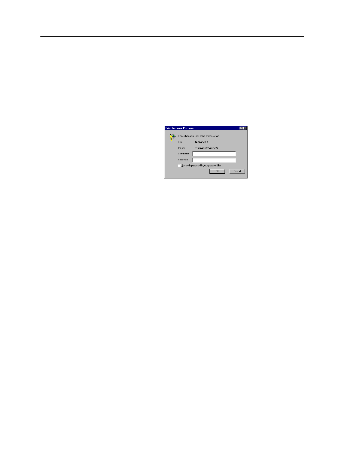
1. Point your web browser to http://xxx.xxx.xxx.xxx, where
xxx.xxx.xxx.xxx is the IP address of the Avaya G350 Device
you want to manage. The Enter Network Password dialog box
opens.
Figure 1-1. Enter Network Password Dialog Box
2. Enter root in the
Password
field. (Use a valid CLI password.)
User Name
field and the correct password in the
3. To save the password on your computer, check the
in your password list
OK
4. Click
—
. The Avaya G350 Welcome page opens.
If the required Java plug-in is installed on your computer, the
checkbox.
Java Plug-in Security Warning dialog box opens after a few
seconds.
—
If the required Java plug-in is not installed, the plug-in is
automatically downloaded to your computer. Follow the
instructions on the Avaya G350 Welcome page to install the
plug-in.
Save this password
4 Avaya G350 Manager User Guide
Page 15

The User Interface
The Avaya G350 Manager user interface is different for each of its
management applications. However, the following elements of the user
interface are common to all views:
Introduction
Application Tabs
You can access the three main components of device management using
the following Application Tabs in the Avaya G350 Manager:
• Application Tabs
Routing Manager, and SMON applications for the Avaya G350
Device.
• Application Area
opens.
• Status Line
Avaya G350 Manager and the Avaya G350 Device.
• Device Manager - View the Avaya G350 Device Manager for
device configuration and Port RMON.
• Device SMON - View SMON (Switch Monitoring) information
for the Avaya G350 Device.
• Routing Manager - View the Avaya G350 Routing configuration.
- Displays the communication status between the
- Tabs for accessing the Device Manager,
- An area where the selected application
To switch to a different view, click the appropriate Application Tab. The
selected application opens.
* Note: When the Avaya G350 Manager is installed as a standalone
manager and when running the Avaya G350 Manager via
Web Management, the Device SMON tab does not appear.
Avaya G350 Manager User Guide 5
Page 16
Chapter 1
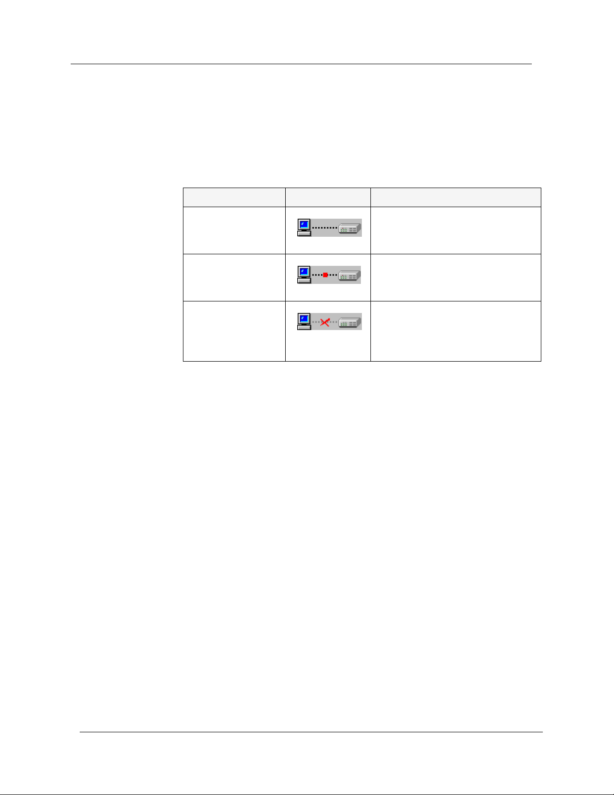
Status Line
The Status Line shows the communication status between the application
and the Avaya G350 Device. The Status Line displays a status message and
an appropriate graphic. The table below shows the possible statuses with
their corresponding graphics, and provides an explanation for each status.
Table 1-1. Communication Statuses
Status Graphic Description
Ready The application is ready to
communicate with the
Avaya G350 Device.
Communicating The application is currently
communicating with the
Avaya G350 Device.
Communication
Error
The last attempted
communication with the
Avaya G350 Device was not
successful.
6 Avaya G350 Manager User Guide
Page 17
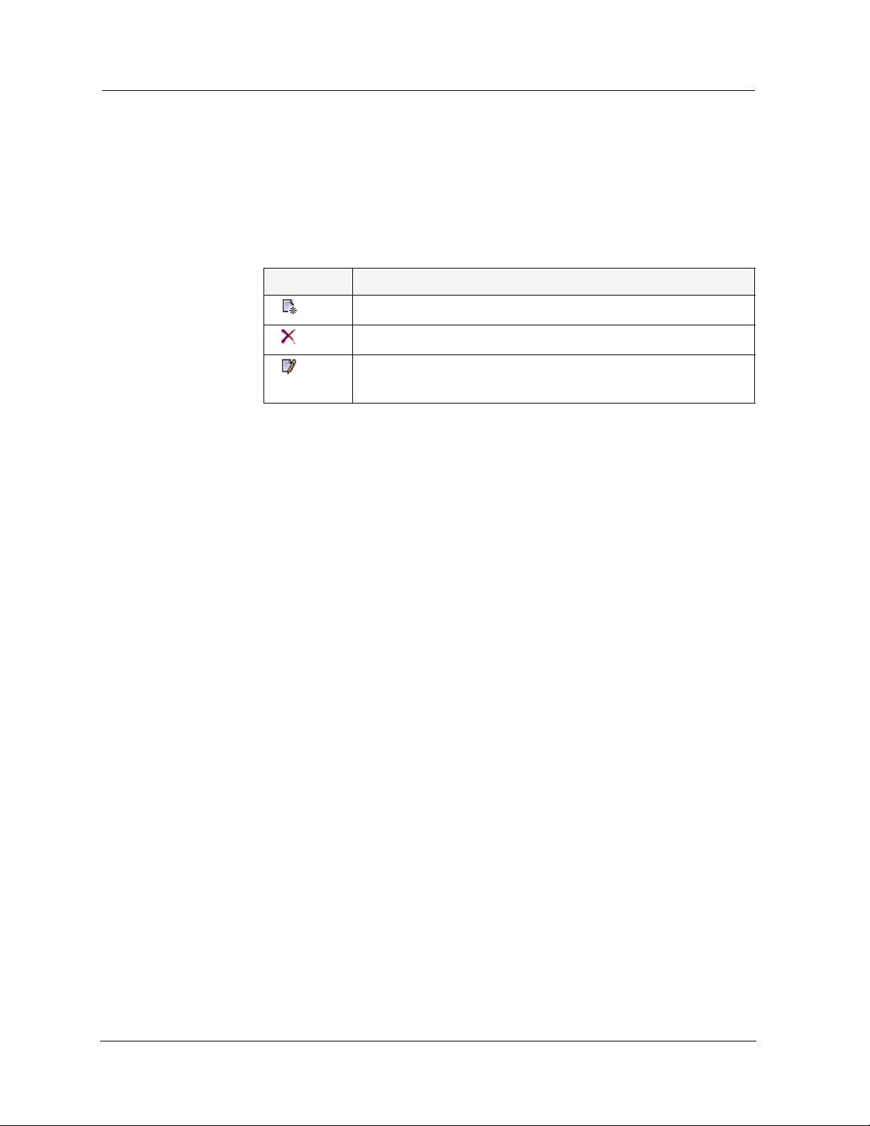
Managing Tables
The Avaya G350 Manager interface displays the status of each row in a
table. The following table shows a list of symbols that can appear at the
start of a table row, with their corresponding explanations.
Symbol Explanation
Introduction
Table 1-2. Table Symbols
The row is a new entry.
The row is to be deleted.
The information in the row has been changed by the
user.
To undo all the changes made to a table, click
Undo
made to a selected row, click
Apply
to update the device.
. When all changes are finalized, click
Refresh
. To undo changes
Avaya G350 Manager User Guide 7
Page 18

2
Device Manager
This chapter provides an introduction to the Avaya G350 Device
Manager. It includes the following sections:
• The User Interface
Manager user interface, including instructions for selecting
elements and using the toolbar buttons.
• Avaya G350 Modes
configuration and Port RMON modes in the Avaya G350 Device
Manager.
• Refreshing Device Information
refresh the information in the Avaya G350 Manager.
• Using Dialog Boxes and Tables
found in the dialog boxes and tables in the Avaya G350 Device
Manager.
• Using Avaya G350 Device Manager Help
the options for accessing on-line help in the Avaya G350 Device
Manager.
The User Interface
The Avaya G350 Device Manager user interface consists of the following
elements:
- An introduction to the Avaya G350 Device
- Instructions on switching between the
- Instructions on how to
- An explanation of the icons
- An explanation of
• Menu Bar - Menus for accessing Avaya G350 Device
management functions. Refer to Appendix A,
• Application Toolbar - Toolbar buttons for accessing
Avaya G350 Device management functions.
• Get/Set Toolbar
configuration of ports.
• Tree View
representation of the modules and ports of the Avaya G350
Device.
• Desktop
floating and minimized dialog boxes and tables are displayed.
Avaya G350 Manager User Guide 8
- A resizeable window containing a hierarchical
- A resizeable window where the Chassis View and all
- Toolbar buttons for viewing and changing the
Menus
Page 19

Device Manager
A
• Chassis View - A graphical representation of the Avaya G350
Device.
• Dialog Area
- A resizeable window where all dialog boxes and
tables first open.
For information on other parts of the user interface, refer to “
The User
Interface” on page 5.
The figure below shows the user interface, with its various parts labeled.
Figure 2-1. The Avaya G350 Device Manager User Interface
pplication
Tabs
Menu
Bar
Application
Toolbar
Tree
View
Get/Set
Toolbar
Chassis
View
Dialog
Area
Status
Line
To resize the three main areas of the user interface, the Tree View, the
Chassis View, and the Dialog Area, use the splitter bars and their arrows.
Application Toolbar
The Application Toolbar provides shortcuts to the main Device Manager
functions.
The table below describes the buttons on the Application Toolbar and
gives the equivalent menu options.
Table 2-1. Application Toolbar
Button Description Menu Item
Sets the Device Manager
to Configuration Mode.
Sets the Device Manager
to Port RMON mode.
Avaya G350 Manager User Guide 9
View > Configuration
View > Port RMON
Page 20

Chapter 2
Table 2-1. Application Toolbar (Continued)
Button Description Menu Item
Shows Switch-Connected
Addresses.
Displays the VLAN
window.
Displays the Port
Redundancy table.
Starts the Port Mirroring
wizard.
Displays the Trap Manager
Table.
Commits configuration
changes.
Launches Avaya Call
Processing on the selected
Media Gateway or Voice
port.
Opens the on-line help.
View > Switch-Connected
Addresses
Configure > VLAN
Configure > Port Redundancy
Configure > Port Mirroring
Configure > Trap Managers
Actions > Commit
Tools > Administer
Station/Gateway
Help > Help On
When you place the cursor on a toolbar icon for one second, a label
appears with the name of the button.
You can toggle the display of the application toolbar. To toggle the display
of the application toolbar, select
Toolbar
Get/Set Toolbar
The Get/Set Toolbar provides buttons for getting and setting configuration
parameters for selected ports. When a port is selected, its configuration is
reflected on the Get/Set Toolbar. Each group of buttons represents the
various possible states of a configuration parameter. For example, the first
group of buttons represents the possible speed of a port - 10 Mbps,
100 Mbps, or 1000 Mbps. If the center button is depressed, the port is
currently configured to operate at 100 Mbps.
Selects a VLAN. Ports that
are not on the selected
VLAN appear dark gray in
the Chassis View.
View > Toolbars > Show Application
.
10 Avaya G350 Manager User Guide
Page 21

Device Manager
Selected ports can be configured using the Get/Set Toolbar. To change the
configuration of a port, click the button that represents the value of the
apply
parameter you want to apply to the port. Click
with the changes. Click
cancel
to discard the changes. Options not
to update the device
applicable to the selected port are greyed out.
Multiple ports can be simultaneously configured using the Get/Set
Toolbar. When multiple ports with non-identical configurations are
selected, only the parameters whose settings are identical on the selected
ports are reflected in the Get/Set Toolbar. For example, if a port operating
at full duplex and a port operating at half duplex are selected, neither of
the duplex mode buttons on the Get/Set Toolbar are depressed.
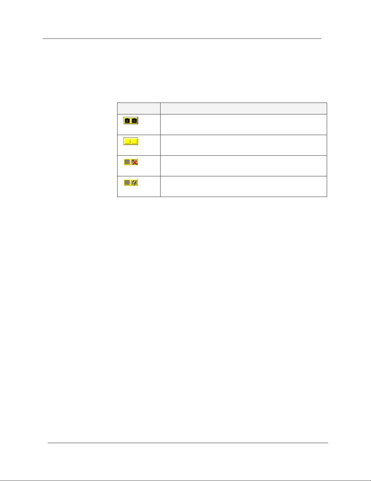
The table below displays the buttons on the Get/Set Toolbar and explains
their functions and settings.
Table 2-2. Get/Set Toolbar
Button Description
Get and set the port’s speed: 10 Mbps, 100 Mbps,
1000 Mbps.
Get and set the port’s status: Enabled, Disabled.
Get and set the port’s mode: Half duplex, Full duplex.
Get and set the port’s auto-negotiation status:
Auto-negotiation Enabled, Auto-negotiation
Disabled.
Get and set the port’s STP mode: Enabled, Disabled.
Get and set the port’s Power over Ethernet
Get and set the port’s priority. Select a priority level
between 1 and 8 using the pull-down listbox.
Apply or cancel the configuration changes made with
the Get/Set Toolbar.
* Note: The Apply/Cancel buttons only appear when changes are
made to the configuration.
You can toggle the display of the Get/Set toolbar. To toggle the display of
the Get/Set toolbar, select
Avaya G350 Manager User Guide 11
View > Toolbars > Show Get/Set Toolbar
.
Page 22

Chapter 2
Tree View
The Tree View shows a hierarchical representation of the structure of the
Avaya G350 Device. To select ports, modules or media modules, click their
icons in the Tree View. When an element is selected in the Tree View, the
corresponding element is selected in the Chassis View.
The highest level of the Tree View represents the device. The second level
shows modules. The third level shows ports. This includes ports on
expansion modules.
To expand the view of a contracted element in the tree or to contract the
view of an expanded element in the tree:
Double-click the element.
Or
Click the handle next to the element you want to expand or
contract.
Desktop
The central section of the application window is the Desktop. This area
can be resized by dragging the vertical splitter bars with the mouse.
Floating dialog boxes and tables can be resized. The Chassis View and
floating dialog boxes and tables can also be minimized. Minimized
windows appear at the bottom of the Desktop.
12 Avaya G350 Manager User Guide
Page 23

Chassis View
Device Manager
The Chassis View is a graphical representation of the Avaya G350 Device.
The Avaya G350 Device can contain several Avaya G350 modules. The
Chassis View shows all of the device’s modules and ports, including ports
on expansion modules (when present). The colors of the modules and
ports in the Chassis View reflect their status.
When you hold the cursor over a port’s icon in the Chassis View, a label
appears with the port number, its VLAN ID, and the last fault that
occurred on the port.
Figure 2-2. Avaya G350 Chassis View
Port
Symbols
Power
Symbols
Module
Identifier
Fixed
Ports
Channel
Group
Symbol
Media
Module
When viewing selected dialog boxes, the color of the port indicates the
status of the port with regard to the application. The port selected to be
the base port appears dark blue. The ports selected to be additional ports
appear cyan.
The following table provides a list of the possible port colors in the Chassis
View and their meaning.
Table 2-3. Chassis View Port Colors
Color Meaning
Green The port is enabled, and its status is Okay.
Yellow The port is enabled, and its status is Warning.
Red The port is enabled, and its status is Fatal.
Light Gray The port is disabled.
Dark Gray The port is not associated with the assignment.
White The port is logically available for assignment.
Dark Blue The port has been assigned the primary position in an
application.
Cyan The port has been assigned a secondary position in an
application.
Avaya G350 Manager User Guide 13
Page 24
Chapter 2
GBIC Ports
The Avaya MM314 media modules contains a GBIC (GigaBit Interface
Converter) port that houses removable transceiver modules. The Chassis
View reflects the management status of this ports. The following table
shows the possible appearances of this port in the Chassis View and
provides the corresponding management status of the port.
Table 2-4. GBIC Port Status
GBIC Port Status
The GBIC port contains a supported transceiver
module.
There is no transceiver module present in the GBIC
port.
The transceiver module in the GBIC port is not
supported.
The transceiver module in the GBIC port is of an
unknown type.
GBIC ports that contain the following types of transceiver modules can be
configured:
Selecting
Elements
• Supported transceiver modules
• No transceiver modules
• Unknown transceiver modules
GBIC ports that contain unsupported transceiver modules cannot be
configured.
You can select modules and ports.
To select a module:
In the Chassis View, click the module’s label.
Or
In the Tree View, click the module’s icon. The module’s label is
highlighted in the Chassis View and the Tree View.
To select a port:
In the Chassis View, click the port.
Or
14 Avaya G350 Manager User Guide
Page 25

Dialog Area
Device Manager
In the Tree View, click the port’s icon. The port is highlighted in the
Chassis View and the Tree View.
—
To select multiple elements, press CTRL while clicking on each
element to be selected.
The area to the right of the Chassis View is where all dialog boxes, tables,
and wizards first appear. This area can be resized by dragging the vertical
splitter bar with the mouse. When a dialog box, table, or wizard opens, it
replaces the current dialog box open in the Dialog Area. To view more
than one dialog box or table simultaneously, click the pushpin in the
upper right-hand corner of the dialog box. The dialog box becomes a
floating dialog box and moves to the Desktop.
To restore a dialog box to the Dialog Area, click the toolbar button or icon
that opened the dialog box. The dialog box returns to the Dialog Area.
Avaya G350 Modes
The Avaya G350 Device Manager has two modes:
• Configuration mode
• Port RMON mode
When in configuration mode, you can view and change the configuration
of the Avaya G350 Device and individual ports. When in Port RMON
mode, you can view graphical representations of the traffic on individual
ports.
To switch to configuration mode:
Click .
Or
Select
To switch to Port RMON mode:
View > Configuration
.
Click .
Or
Select
Avaya G350 Manager User Guide 15
View > Port RMON
.
Page 26

Chapter 2
Refreshing Device Information
You can refresh the information in the Avaya G350 Device Manager. To
refresh Avaya G350 device information, select
Avaya G350 Device Manager refreshes its device information and updates
the display.
Using Dialog Boxes and Tables
Dialog boxes and tables in the Avaya G350 Manager application have a
common set of buttons. The following table displays the buttons and
explains their functions:
Table 2-5. Dialog Box Icons
Icon Function
View > Refresh
. The
Refresh
Apply
Insert
Wizard
Delete
Undo
Refreshes the information in the table or dialog box. This
clears any changes made to the table or dialog box and not
yet sent to the device.
Sends the information from the table or dialog box to
update the device.
Adds a row to the table.
Starts a wizard.
Deletes the selected rows of the table.
Undoes all changes to the selected row in a table.
16 Avaya G350 Manager User Guide
Page 27

Using Avaya G350 Device Manager Help
This section explains how to use the on-line help in the Avaya G350
Device Manager. The on-line help can be opened to the contents page or
directly to a topic of interest.
* Note: When running the Avaya G350 Manager via Web
Management, on-line help is only available if you have
installed the on-line help on your network and configured the
Avaya G350 Device with the location of the help files. For
information on installing the on-line help and configuring the
device with the location of the files, refer to the Avaya G350
User’s Guide.
Opening the Help to the Contents Page
Device Manager
To open the help to the contents page, select
help opens to the contents page.
Opening the Help to a Topic of Interest
To open the help directly to a topic of interest:
1. Click .
Or
Select
with a question mark.
2. Click on a point of interest in the Avaya G350 Device Manager. The
on-line help opens to a topic explaining the feature that was
clicked.
Help > Help On
. The cursor changes to the shape of an arrow
Help > Contents
. The on-line
Avaya G350 Manager User Guide 17
Page 28

3
Device Configuration
This chapter explains how to view and set the various configuration
parameters relevant to the Avaya G350. It includes the following
sections:
• Viewing
about the Avaya G350 Device.
• Viewing
an Avaya G350 module in the device.
• Viewing
ports on the Avaya G350 Device.
• Resetting the Device
To view configuration information, you must be in Configuration mode.
To switch to Configuration mode:
Click .
Or
Select
Device Information
Module Configuration - View information specific to
Port Configuration
- Reset the Avaya G350 Device.
View > Configuration
- View high-level information
- View information specific to the
.
Avaya G350 Manager User Guide 18
Page 29

Viewing Device Information
The Device Information dialog box provides you with high-level
information specific to the Avaya G350 Device. This information is
divided into the following:
Device Configuration
• Device Information - General Tab
information about the device such as the device’s name, addresses,
contact person, location, type, description, the number of modules
in the device, and the management VLAN ID.
• Media Gateway Configuration Tab - Provides detailed
information on the configuration settings of the Media Gateway
function of the device. For more information on Media Gateway
Configuration, refer to Chapter 5,
• Media Gateway Controller Configuration Tab - Provides
detailed Quality of Service statistics for the Media Gateway
function of the device. For more information, refer to Chapter 5,
Media Gateway Functions
• Voice over IP Resources Tab - Provides administration
parameters for the VoIP engine. For more information on VoIP
Resources, refer to Chapter 6,
• Voice over IP Status Tab - Provides detailed operational statistics
for the VoIP engine. For more information, refer to Chapter 6,
Engine Configuration
.
VoIP Engine Configuration
.
- Provides detailed
Media Gateway Functions
.
.
VoIP
Avaya G350 Manager User Guide 19
Page 30

Chapter 3
Device Information - General Tab
To view the General tab of the Device Information dialog box, select
Configure > Device Information
to the General tab.
Figure 3-1. Device Information Dialog Box - General Tab
. The Device Information dialog box opens
The following table provides a list of the fields in the General tab of the
Device Information dialog box and their descriptions.
Table 3-1. Device Information Fields - General Tab
Field Description
System Name
Logical name of the device, as defined on the
SNMP agent of the device.
MG Identifier
FW version
Contact
Identification number of the Media Gateway.
Firmware release the device is running.
The individual responsible for the
maintenance of this device.
Physical Location
System Description
20 Avaya G350 Manager User Guide
The current physical location of this device.
A description of the device.
Page 31

Device Configuration
Table 3-1. Device Information Fields - General Tab (Continued)
Field Description
Number Of Modules
VLAN MAC Address
Current DS Mode
Next DS Mode
Current PMI Interface
Current PMI IP Address
Current PMI Subnet
Mask
Next PMI Interface
The number of Media Modules and expansion
modules in the chassis.
The MAC address of the VLAN interface.
Speed of serial link. Possible values are:
• T1
• E1
Speed of backup serial link, if configured.
Possible values are:
• T1
• E1
Interface currently designated as Primary
Management Interface.
IP address of Primary Management Interface.
Subnet mask of Primary Management
Interface.
Interface designated as backup Primary
Management Interface.
Next PMI IP Address
IP address of backup Primary Management
Interface.
Default Gateway
IP address of the default network gateway
device.
ICC VLAN
VLAN of which the device is a member.
For more information on the user interface, refer to “Using Dialog Boxes
and Tables” on page 16.
Avaya G350 Manager User Guide 21
Page 32

Chapter 3
Viewing Module Configuration
The Module Configuration dialog box provides you with information
specific to a selected module.
• Module Configuration - General Tab
information about the module, such as the module’s position in
the device, the module’s type, description, number of ports, mode
of operation, and any faults occurring on the module.
• Module Configuration - Power Tab - Provides information
about the module’s Power over Ethernet (PoE) configuration. For
more information, refer to Chapter 4,
* Note: The information fields in the Module Configuration dialog
box vary according to the type of module selected.
- Provides detailed
Power Over Ethernet
.
22 Avaya G350 Manager User Guide
Page 33

Module Configuration - General Tab
To view the General tab of the Module Configuration dialog box for a
selected module:
Click the module symbol in the Tree View.
Or
Click the module’s label in the Chassis View. The Module
Configuration dialog box opens to the General tab.
Figure 3-2. Module Configuration Dialog Box - General Tab
Device Configuration
* Note: Module Configuration fields may vary somewhat based on the
Media Module.
Avaya G350 Manager User Guide 23
Page 34

Chapter 3
The following table provides a list of the fields in the Module
Configuration dialog box and their descriptions.
Table 3-2. Module Configuration Dialog Box
Field Description
MM Type
MM Description
Serial #
HW Version
Model of Media Module. Possible values
include:
• MM312
• MM314
• MM340
• MM342
• MM710
• MM711
• MM712
• MM714
• MM720
• MM722
• S8300
Description of Media Module.
Unique identifier for individual Media
Module.
Release version of Media Module hardware.
FW Version
Number of Ports
Operational Status
Release version of Media Module firmware.
The number of ports in the Media Module.
The operational status of the Media Module.
Possible values are:
• OK - Media Module is operating
normally.
• Down - Media Module is reporting
faults making it unable to function.
• Fatal - Media Module is reporting faults
that are unrecoverable.
Fault Messages
Number of fault messages reported by the
Media Module.
For more information on the user interface, refer to “
Using Dialog Boxes
and Tables” on page 16.
24 Avaya G350 Manager User Guide
Page 35

Viewing Port Configuration
The Port Configuration dialog box contains tabs that provide you with
information specific to a selected port.
Device Configuration
• Port Configuration - General Tab
information about the port, such as the port name, type,
functionality, status, VLAN ID, mode of operation, and any faults
occurring on the port.
• Port Configuration - Advanced Tab
information about the port’s STP configuration and port
classification.
• Port Configuration - Power Tab - Provides information about
the port’s PoE configuration. For more information about PoE,
refer to Chapter 4,
• Get/Set Toolbar - Provides an alternative, quick method to view
and change the port’s configuration. For more information on the
Get/Set Toolbar, refer to “
Power Over Ethernet
Get/Set Toolbar” on page 10.
- Provides detailed
- Provides detailed
.
Avaya G350 Manager User Guide 25
Page 36

Chapter 3
Port Configuration - General Tab
To view the General tab of the Port Configuration dialog box for a selected
port:
Click the port symbol in the Chassis View.
Or
Click the port’s icon in the Tree View. The Port Configuration
dialog box opens to the General tab.
Figure 3-3. Port Configuration Dialog Box - General Tab
The following table provides a list of the fields in the Module
Configuration dialog box and their descriptions.
* Note: Some fields will vary based on the Media Module the port is
resident in.
Table 3-3. Module Configuration Dialog Box
Field Description
Port Name
26 Avaya G350 Manager User Guide
The user can define a logical name to the port
for ease of use.
Page 37

Device Configuration
Table 3-3. Module Configuration Dialog Box (Continued)
Field Description
Port Type
Port Functionality
Administrative Status
Tagging Mode
The port type; optionally includes reference to
the module to which it is attached and port
connector type.
The physical media type of the selected port. If
the port conforms to a certain standard
(Repeater, Transceiver, 10BaseT, etc.), this
standard is displayed. If the port does not
conform to any standard, Private is displayed.
The administrative state of the selected port:
Enabled
•
- The port is enabled and can
transmit and receive packets.
Disabled
•
- The port is disabled and
cannot transmit or receive packets.
The port’s operational mode regarding VLANs.
The possible modes are:
Clear
•
- Transmits each outgoing packet in
untagged format if it belongs to the port’s
VLAN. Otherwise, it discards the packet.
IEEE-802.1Q
•
- VLAN tagging, per IEEE
802.1Q VLAN standard. The port will
transmit frames with a VLAN ID of
1 - 3071.
VLAN ID
Port Priority Level
The VLAN number of the port.
The priority level of packets exiting the port or
ports on the module. For effective
transmission, multimedia packets must be
received at regular intervals. To ensure this,
you can assign priorities to packets coming out
of a port.
Whenever traffic load is extreme and a port
cannot accept all incoming packets, packets
sent from a port with the highest priority will
pass through first. However, a fairness
mechanism will allow low priority packets to
eventually enter the bus.
Possible values are
Priority 7
Avaya G350 Manager User Guide 27
User Priority 0...User
Page 38

Chapter 3
Table 3-3. Module Configuration Dialog Box (Continued)
Field Description
Auto Negotiation
Mode
Auto Negotiation
Status
The configured state of the Auto-Negotiation
protocol between two stations. When enabled,
Auto-Negotiation detects the highest common
denominator for communication between
endstations, and sets both to the same highest
common setting. It also delivers remote link
status.
For 10BaseT and 100BaseT ports,
Auto-Negotiation determines the speed and
Duplex Mode of communication between the
endstations. For Gigabit ports, AutoNegotiation determines the Flow Control
setting of the ports.
For more information, refer to Auto-Negotiation
in The Reference Guide.
The operational state of the Auto-Negotiation
protocol between two stations. Possible
statuses are:
Pass
•
- The Auto-Negotiation protocol is
enabled and a common protocol has
been established.
Duplex Mode
In progress
•
- The Auto-Negotiation
protocol is in the process of detecting the
communication capabilities of the
endstations and setting them to the
highest common denominator.
Fail
•
- The Auto-Negotiation protocol was
not able to detect the communication
capabilities of the end station, or was
unable to set them to the highest
common denominator.
Disabled
•
- The Auto-Negotiation protocol
is disabled.
The state of communication of the selected
port. Possible values are:
Full Duplex
•
- The port can send and
receive simultaneously.
Half Duplex
•
- The port can either receive
or send, but cannot do both
simultaneously.
28 Avaya G350 Manager User Guide
Page 39

Device Configuration
Table 3-3. Module Configuration Dialog Box (Continued)
Field Description
Speed Mode
The rate of communication of the selected
port. Possible values are:
• Ethernet
• Fast Ethernet
• Gigabit Ethernet
Flow Control Mode
Operational Status
The state of flow control on the selected port.
The warning level of the selected port.
Possible values are:
• OK
• Warning
• Fatal
Fault Messages
A list of fault messages.
For more information on the user interface, refer to “Using Dialog Boxes
and Tables” on page 16.
Avaya G350 Manager User Guide 29
Page 40

Chapter 3
Port Configuration - Advanced Tab
To view the Advanced tab of the Port Configuration dialog box for a
selected port:
1. Click the port symbol in the Chassis View.
Or
Click the port’s icon in the Tree View. The Port Configuration
dialog box opens to the General tab.
2. Click
Advanced
box appears.
Figure 3-4. Port Configuration Dialog Box - Advanced Tab
. The Advanced tab of the Port Configuration dialog
.
Table 3-4. Module Configuration Dialog Box
Field Description
Port STP Mode
30 Avaya G350 Manager User Guide
Configured status of Spanning Tree. Possible
values are:
• Enable
• Disable
Page 41

Device Configuration
Table 3-4. Module Configuration Dialog Box (Continued)
Field Description
Port STP State
STP Admin Edge
STP Oper Edge
Spanning Tree state on the port. Possible
values are:
• Blocking - Port is blocking attempts to
join Spanning Tree.
• Listening - Port is discovering other
devices in the Spanning Tree.
• Learning - Port is calculating Spanning
Tree values prior to joining the Spanning
Tree.
• Forwarding - Port is forwarding traffic
within the Spanning Tree.
The administrative state of the edge port
parameter. Possible states include:
• TRUE - This port is assumed to be an
edge port.
• FAL SE - This port is assumed not to be
an edge-port.
The operational state of the edge port
parameter.
STP Admin P2P
• TRUE - This port is operating in the state
specified in STP Admin Edge.
• FAL SE - A BPDU was received by the
port.
The administrative point-to-point status of the
LAN segment attached to this port. Possible
statuses include:
• True - The port should always be treated
as if it is connected to a point-to-point
link.
• forceFalse - The port should be treated
as having a shared media connection.
• auto - The port is considered to have a
point-to-point link if it is an Aggregator
and all of its members are aggregative, or
if the MAC entity is configured for full
duplex operation, either through
auto-negotiation or by management
means.
Avaya G350 Manager User Guide 31
Page 42

Chapter 3
Table 3-4. Module Configuration Dialog Box (Continued)
Field Description
STP Oper P2P
STP Admin Path Cost
STP Path Cost
STP Priority
The operational point-to-point status of the
LAN segment attached to this port. It indicates
whether a port is considered to have a
point-to-point connection or not.
The value is determined by STP Admin P2P.
The administratively assigned value for the
contribution of this port to the path cost of
paths towards the spanning tree root. A value
of 0 assigns the automatically calculated
default Path Cost value to the port.
STP Admin Path Cost complements STP Path
Cost, which returns the operational value of
the path cost.
The operational cost factor used by Spanning
Tree Protocol to determine the most efficient
route for forwarding traffic to its destination
while removing loops in the network.
For more information refer to Spanning Tree
Protocol (STA) in The Reference Guide.
The priority factor used by STP to determine
the activity status of an individual port on the
Spanning Tree.
STP Force Migration
When checked and in RSTP mode, the port is
forced to transmit RSTP BPDUs.
Port Classification
The classification of a specific port. Port
Classification allows network managers to
specify each port level’s importance. The
possible states are:
Regular
•
Valuable
•
- Normal users.
- Servers or critical users.
For more information refer to Port Classification
in The Reference Guide.
For more information on the user interface, refer to “Using Dialog Boxes
and Tables” on page 16.
32 Avaya G350 Manager User Guide
Page 43

Resetting the Device
You can reset the entire Avaya G350 Device, or one or more of its
individual modules.
To reset the entire Avaya G350 Device:
Device Configuration
1. Select
2. Click
To reset an individual Avaya G350 module:
1. Click the label of the module you want to reset.
—
2. Select
opens.
3. Click
Action > Reset Device
Yes
. The device resets.
To select multiple modules, press CTRL while clicking
additional module labels.
Actions > Reset Expansion Module
Yes
. The selected module resets.
. A confirmation dialog box opens.
. A confirmation dialog box
Avaya G350 Manager User Guide 33
Page 44

Chapter 3
34 Avaya G350 Manager User Guide
Page 45

4
Power Over Ethernet
This chapter provides information about Power over Ethernet (PoE) and
includes the following sections:
• PoE Overview
• Viewing PoE Information
PoE Overview
PoE provides power to IP telephones over an Ethernet line using an
Avaya G350 device. The power is transmitted via the device’s ports to the
IP telephones over the same cable carrying IP packets.
The Avaya G350 device automatically discovers the connection and
removal of IP telephones from the in-line powered ports and provides
power accordingly.
The Avaya G350 provides the power using an internal 225 watt power
supply over a 48 volt feed. It is possible to attach an external power
supply either for additional power, or as an alternative power supply
should the internal power supply fail.
- An overview of Power over Ethernet
functionality in Avaya G350 devices.
- Information about viewing PoE
port information and configuring PoE on a module and port level.
In addition, you can configure power priorities per port ensuring that
important equipment is guaranteed power whenever necessary.
Avaya G350 Manager User Guide 35
Page 46

Chapter 4
Viewing PoE Information
This section provides information about viewing port information and
configuring PoE on the port and module level, and includes the following:
• Viewing PoE Port Information
• Viewing PoE Configuration
Viewing PoE Port Information
The Chassis View provides immediate information about PoE. Ports that
are currently supplying power to IP telephones are labeled with a
lightning bolt.
Viewing PoE Configuration
You can view PoE configuration information on the module and port
levels.
36 Avaya G350 Manager User Guide
Page 47

Power Over Ethernet
PoE Module
Configuration
To view the PoE configuration on a module that supports PoE, select the
Power
tab in the module’s configuration dialog box. For information on
opening the Module Configuration dialog box, refer to “
Viewing Module
Configuration” on page 22.
Figure 4-1. Module Configuration - Power Tab
The following table provides a list of the fields in the Power tab of the
Module Configuration dialog box and their descriptions:
Table 4-1. Module Configuration - Power Fields
Field Description
Total PoE Available
Power available to distribute to devices
connected to this module.
Total PoE Drawn
Total power currently distributed to devices
connected to this module.
PoE Usage Threshold
The usage threshold expressed in percentage
for comparing the measured power and
initiating an alarm if the threshold is
exceeded. Possible values are 1-99.
Avaya G350 Manager User Guide 37
Page 48

Chapter 4
PoE Port
Configuration
To view the PoE configuration on a port that supports PoE, select the
Power
tab in the port’s configuration dialog box. For more information on
opening the Port Configuration dialog box, refer to “
Configuration” on page 25.
Figure 4-2. Port Configuration - Power Tab
Viewing Port
The following table provides a list of the fields in the Power tab of the
Module Configuration dialog box and their descriptions:
Table 4-2. Port Configuration - Power Fields
Field Description
Administrative Status
38 Avaya G350 Manager User Guide
The administrative state of power on this port.
Possible states include:
• Enable - This port can supply power to
IP telephones.
• Disable - This port cannot supply power
to IP telephones.
Page 49

Power Over Ethernet
Table 4-2. Port Configuration - Power Fields (Continued)
Field Description
Detection Status
Power Priority
Power Maintenance
The operational state of power on this port.
Possible states include:
• Searching - Port is currently being
polled.
• OK - This port is supplying power to an
IP telephone.
• Failed - This port is currently not
supplying power to an IP telephone.
The priority of the power being supplied by
this port. When the demand for power
exceeds the modules capacity, ports with
lower priority will be prevented from
supplying power before ports with a higher
priority. Possible priorities include:
• Critical
• High
• Low
The port’s operational power status. Possible
statuses include:
• OK - The port current is within the
normal range.
• Under Current - The port current is
below the minimum acceptable value.
• MPS Absent - Unable to detect power
status.
Avaya G350 Manager User Guide 39
Page 50

5
Media Gateway Functions
This chapter provides information about the Avaya G350’s Media
Gateway functionality and includes the following sections:
• Media Gateway Overview
functionality in Avaya G350 Devices.
• Media Gateway Configuration
and configuring Media Gateway components.
• Avaya Site Administration
gatekeeper software.
Media Gateway Overview
The Media Gateway is a family of components, which can deliver data,
voice, fax, and messaging capabilities over an IP network. It is a VoIP
system that acts as an IP PBX and messaging server and a VoIP gateway.
In addition, it performs the function of a gatekeeper and an IP media
management resource for tone detection and generation, conferencing,
and call classification.
The Media Gateway components are controlled through the Media
Gateway Processor (MGP). The MGP detects when a media module is
inserted or removed and transfers information from the VoIP engine to
the other components.
- An overview of Media Gateway
- Information about viewing
- Information about Avaya’s
The Avaya G350’s Media Gateway converges the power of Avaya Call
Processing (ACP) software with the power of distributed switching from
the Avaya G350 Device. It provides IP PBX functionality using open
standards and an open operating system. The device connects to ACP
using either an internal or external call controller. The ACP serves as the
G350’s gatekeeper.
Avaya G350 Manager User Guide 40
Page 51

Media Gateway Configuration
This section describes how to view and set the various configuration
parameters relevant to the G350 Media Gateway. It includes the following
sections:
Media Gateway Functions
• Viewing
specific to a G350 Media Gateway module in the device.
• Viewing
specific to a Media Module in the device.
Media Gateway Configuration - View information
Media Module Configuration - View information
Viewing Media Gateway Configuration
The Media Gateway Configuration dialog box provides you with
information about a selected module. To view the configuration of the
Media Gateway:
1. Select
2. Select the MG Config tab. The MG Config dialog box opens.
Configure > Device Configuration
box opens.
. The Device Manager dialog
Avaya G350 Manager User Guide 41
Page 52

Chapter 5
MG Config
The MG Config tab provides information about the Media Gateway QOS
parameters.
Figure 5-1. MG Config Tab
The following table lists the fields in the MG Config tab of the Module
Configuration dialog box and their descriptions.
Table 5-1. MG Config Parameters
Field Description
QoS Control
The source of QoS control. This parameter can
only be changed via the CLI. Possible values are:
• Local - The processor is using the local
QoS parameters. The 802 priority and
DSCP fields can be configured.
• Remote - The processor is receiving QoS
parameters from a remote Media Gateway.
All QoS parameters are read only.
DSCP
Priority based on a technology by which packets
are marked in the IP header Type of Service
(ToS) byte as belonging to a specific class.
Possible values are 0 - 63.
42 Avaya G350 Manager User Guide
Page 53

Table 5-1. MG Config Parameters (Continued)
Field Description
Media Gateway Functions
MGC Config
802 Priority
Priority based on the 802.1p standard, which
assigns rights and privileges to users on a
telephony network. Possible values are 0 - 7.
Operational Status
Operational Status of the Media Gateway.
Possible values are:
• OK - Media Gateway is operating
properly.
• Fatal - Media Gateway is down.
Fault Messages
A list of fault messages.
The MGC Config tab provides information about the Media Gateway
Controller’s settings, IP address, and registration information.
Figure 5-2. MGC Config Tab
The MGC registers with the Media Gateway, after which it receives its IP
address from the Media Gateway. After you register, the Link Status will
be
Up,
and an IP address will appear.
Avaya G350 Manager User Guide 43
Page 54

Chapter 5
The following table lists the MGC IP Settings fields and their descriptions.
Table 5-2. MGC Config - MGC IP Settings Parameters
Field Description
MGC IP Address
Registered status
H248 Link status
Configurable MGC
list
The IP address of the call controller serving the
media gateway.
Shows whether this media gateway is currently
registered with any call controller.
Status of the link connecting the media gateway
to the active call controller.
A list of Media Gateway Controllers accessible
to the G350.
44 Avaya G350 Manager User Guide
Page 55

Viewing Media Module Configuration
To view the Media Module Configuration dialog box:
In Configuration Mode, click the Media Module symbol in the Tree
View.
Or
Click the Media Module’s label in the Chassis View. The Media
Module Configuration dialog box opens.
Figure 5-3. Media Module Configuration Dialog Box
Media Gateway Functions
The Media Module Configuration dialog box provides information about
a specific media module, including a brief description of the media
module, the number of ports, and its operational status.
Avaya G350 Manager User Guide 45
Page 56

Chapter 5
The following table lists the fields in the Media Module Configuration
dialog box and their description.
Table 5-3. Media Module Configuration Parameters
Field Description
MM Type
MM Description
Serial #
HW Version
FW Version
Number of Ports
Operational Status
Fault Messages
The type of Media Module. Possible values are:
• E1/T1
• ISDN BRI
• Analog
• Digital
• ICC
An optional description of the specific Media
Module.
The serial number of the Media Module.
The version of the Media Module’s hardware.
The firmware version of the Media Module.
The number of ports on the Media Module.
The operational status of the Media Module.
A list of fault messages.
Avaya Site Administration
Avaya Site Administration (ASA) is an administration tool for Avaya Call
Processing call control software. ASA is used to configure the current
MGC or an individual voice port.
To launch ASA on an MGC or voice port:
1. Click the component in the Tree View or Chassis View.
2. Click .
Or
Select
configuration form of the selected component.
46 Avaya G350 Manager User Guide
Action > Administer Station/Gateway
. ASA opens with the
Page 57

Media Gateway Functions
If you have a registered call controller MM installed in your G350 Media
Gateway, you can launch ASA on the call controller. To launch ASA on a
registered call controller Media Module:
1. Select the registered call controller Media Module.
2. Select
Tools > Administer Call Controller
. ASA opens on the selected
call controller.
For more information about ASA, refer to Definity Enterprise
Management documentation.
Avaya G350 Manager User Guide 47
Page 58

6
VoIP Engine Configuration
This chapter provides information and instructions for viewing and
configuring the VoIP Engine features. It includes the following sections:
• VoIP Overview
• VoIP Resources
• VoIP Status
VoIP Overview
The VoIP Engine translates information between different VoIP and data
protocols. The Media Gateway comes with an internal VoIP engine that
supports up to 32 simultaneous sessions.
You can view information and configure parameters for the VoIP Engine
using the VoIP Engine dialog box. To view the VoIP Engine dialog box:
In the Device Manager dialog box, there are two tabs for managing the
VoIP engi n e :
- An overview of VoIP Engine functionality
within the Media Gateway.
- Instructions for viewing and configuring VoIP
Engine Parameters.
- Instructions for determining operational status of
the VoIP Engine.
Select
View > Configure.
The Device Manager dialog box opens.
• VoIP Resources
• VoIP Status
Avaya G350 Manager User Guide 48
Page 59

VoIP Resources
The
VoIP engines, such as QoS parameters, RTCP configuration, and RSVP
configuration.
VoIP resources
VoIP Engine Configuration
tab provides administration parameters common to all
Figure 6-1. VoIP resources Tab
General
The upper section of this dialog box displays general information common
to all VoIP engines.
The following table lists the general fields in the
VoIP resources
tab of the
VoIP Engine dialog box and their description.
Table 6-1. VoIP resources - General Parameters
Field Description
RTP Port min
The minimum range of UDP ports assigned by
the call controller for RTP traffic. The value
ranges between 1 - 65534.
RTP Port max
The maximum range of UDP ports assigned by
the call controller for RTP traffic. The value
ranges between 3 - 65535.
Avaya G350 Manager User Guide 49
Page 60

Chapter 6
Table 6-1. VoIP resources - General Parameters (Continued)
Field Description
QOS Control
The source of QoS control. This parameter can
only be changed via the CLI. Possible values are:
• Local - The processor uses the local QoS
parameters. If the processor is using the
local QoS parameters, the
DSCP
, and
BBE DSCP
fields can be
802 Priority, EF
configured.
• Remote - The processor receives its QoS
parameters from the Media Gateway
Controller. All QoS parameters are readonly.
QoS
QoS can be controlled either locally or remotely. If control is local, it is
possible to configure QoS, RTCP, and RSVP parameters. If control is
remote, QoS parameters are determined by the MGC.
The following table lists the QoS fields and their descriptions.
Table 6-2. VoIP resources - QoS Parameters
Field Description
802 Priority
Priority based on a CoS standard which assigns
rights and privileges to users of a telephony
network. Possible values are 0 - 7.
EF DSCP
A type of differentiated service used to provide
guaranteed bandwidth across a network.
If sufficient bandwidth is available, the
Expedited Forwarding class can be used.
The values range are 0 - 63.
BBE DSCP
A DiffServ class which is used per call to achieve
the greatest possible bandwidth. The values
range between 0 - 63.
50 Avaya G350 Manager User Guide
Page 61

VoIP Engine Configuration
RTCP Monitoring
RTCP is an IP protocol that is used to monitor the quality of RTP packets.
Quality is measured in terms of delay, jitter, and packet loss.
If RTCP monitoring is enabled, the VoIP engines send RTCP packets to the
RTCP monitor. You must configure an IP address for the RTCP monitor,
and determine intervals at which the RTCP data is checked.
The following table lists the RTCP monitoring fields and their descriptions.
Table 6-3. VoIP resources - RTCP monitoring Parameters
Field Description
Monitoring enabled
The status of RTCP monitoring.
• Checked - RTCP monitoring is enabled.
• Unchecked - RTCP monitoring is
disabled.
IP address
Port
Report Period
The IP address of the RTCP monitor.
The port monitored by RTCP.
The interval for RTCP reports.
RSVP
RSVP is a protocol that signals the router to reserve bandwidth.
If RSVP is enabled, the Media Gateway tries to reserve a specific amount
of bandwidth per call session. If this fails, the Media Gateway tries to
reallocate the bandwidth during the call session.
The following table lists the RSVP fields and their description.
Table 6-4. VoIP resources - RSVP Parameters
Field Description
RSVP Enabled
The Status of RSVP usage.
• Checked - The Media Gateway will try to
reserve bandwidth per call. If it fails, the
Media Gateway will try again during the
call.
• Unchecked - RSVP is not enabled.
Avaya G350 Manager User Guide 51
Page 62

Chapter 6
Table 6-4. VoIP resources - RSVP Parameters (Continued)
Field Description
VoIP Status
Retry on failure
The action the VoIP engine takes after an RSVP
request fails.
• Checked - The VoIP engine resends a
RSVP request if the first attempt failed.
• Unchecked - The VoIP Engine drops the
RSVP request, and the Retry Delay field is
ignored.
Retry Delay
The interval the VoIP Engine waits after a failed
RSVP request before sending the new request.
The interval ranges between 0.5 - 60 seconds.
Service profile
VoIP status
The
tab provides information about a specific engine’s
The type of service being provided.
operational status, jitter buffer size, and number of sessions open.
Figure 6-2. VoIP status Tab
52 Avaya G350 Manager User Guide
Page 63

VoIP Engine Configuration
The information in the
VoIP status
tab is provided by the VoIP engine and is
refreshed periodically.
The following table lists the fields in the
descriptions.
Table 6-5. VoIP status Parameters
Field Description
Slot
Channels in Use
Total Voice Channels
Jitter Buffer size
The slot the VoIP engine resides in.
The number of channels currently being used.
The total number of voice channels available.
The jitter buffer is a temporary storage area
built into the receiver of each gateway. It uses a
mechanism to remove the random delays
between packets, which occur as the packets are
routed through the network.
VoIP State
Operational Status
The state of the VoIP engine.
The operational status of the VoIP engine.
VoIP status
tab and their
Avaya G350 Manager User Guide 53
Page 64

7
WAN Configuration
This chapter provides information about configuring Avaya WAN
Expansion Modules and includes the following sections:
• WAN Overview
Avaya G350 Devices.
• WAN Expansion Module Configuration
viewing and configuring WAN functions on the G350.
• E1/T1 Port Configuration
configuring E1/T1 ports in WAN Expansion Modules.
• Viewing Channel Group Information
viewing and configuring channel groups on E1/T1 ports.
• Managing Channel Groups
channel groups on E1/T1 ports.
• USP Configuration
configuring the Universal Serial ports (USPs) on a WAN
Expansion Module.
• Backup Interface Configuration
and configuring Backup interfaces.
- An overview of WAN functionality in
- Information about
- Information about viewing and
- Information about
- Information about managing
- Information about viewing and
- Information about viewing
WAN Overview
WAN Expansion Modules add WAN connectivity to the Avaya G350 line.
WAN connectivity provides a link to the WAN, enabling heavy data
transfer over long distances. A WAN connection can connect branch
offices to headquarters. In addition, WAN connectivity is essential for
providing access to the Internet.
Avaya G350 Manager User Guide 54
Page 65

WAN Expansion Module Configuration
The WAN Expansion Module configuration dialog box provides you with
information specific to a selected WAN expansion module. To view the
configuration of an expansion module:
Click the expansion module symbol in the Tree View.
Or
Click the expansion module’s label in the Chassis View. The
Expansion Module dialog box opens.
Figure 7-1. Expansion Module Dialog Box
WAN Configuration
The Expansion Module dialog box provides detailed information about
the module, such as the module’s description, type, ID, and serial number.
For information about the fields in the Expansion Module dialog box,
refer to “
To apply changes to the WAN module configuration, click
Avaya G350 Manager User Guide 55
Viewing Module Configuration” on page 22.
Apply
.
Page 66

Chapter 7
To save the changes to the WAN module configuration to the startup
configuration, click on the Toolbar. The configuration
changes are saved.
E1/T1 Port Configuration
In addition to the Ethernet ports found on an Avaya G350 device, the
WAN expansion module may have E1/T1 ports. This section provides
information on viewing and configuring E1/T1 port parameters.
To display the E1/T1 Port Configuration dialog box, click the E1/T1 port’s
symbol in the Chassis View or the Tree View. The E1/T1 Port
Configuration dialog box opens.
Figure 7-2. E1/T1 Port Configuration Dialog Box
The E1/T1 port is used to connect to an E1 or T1 line. The E1/T1 Port
Configuration dialog box provides configuration and status information
about the E1/T1 port.
56 Avaya G350 Manager User Guide
Page 67

WAN Configuration
The following table lists the E1/T1 Port Configuration fields and their
descriptions:
Table 7-1. E1/T1 Port Configuration Parameters
Field Description
Description
Port Type
Port Functionality
Administrative Status
Operational Status
Framing
The E1/T1 port description.
The type of E1/T1 port. Possible values are:
• E1 - For E1 and ISDN lines with 32
available channels.
• T1 - For T1 lines with 24 available
channels.
The type of E1 or T1 line.
The state of the selected port. Possible values
are:
• Enabled - The port is enabled and can
transmit and receive packets.
• Disabled - The port is disabled and cannot
transmit or receive packets.
The operational status of the port.
The type of framing.
For an E1 line:
• CRC4
• no-CRC4
• Unframed
* Note: If Unframed is selected, all channels are
used for an unframed Channel Group,
and the Advanced tab does not appear in
the Channel Group dialog box.
For a T1 line:
• ESF
• SF
Avaya G350 Manager User Guide 57
Page 68

Chapter 7
Table 7-1. E1/T1 Port Configuration Parameters (Continued)
Field Description
Linecode
The type of linecode. Possible values are:
For an E1 line:
• HDB3
• AMI
For a T1 line:
• B8ZS
• AMI
Cablelength
(T1
The recommended maximum cable length.
only)
Gain
(T1 only) The gain on this interface.
Clock Source
The source of the Transmit Clock. Possible
sources include:
• Line - The recovered receive clock is used
as the transmit clock.
• Internal - The local clock is used as the
transmit clock.
FDL
(T1 only) The type of FDL used on this interface. Possible
types include:
Local Loopback
Remote Loopback
(T1 only)
• ANSI
• AT&T
• Both - ANSI and AT&T FDl are both used
on this interface.
A request to use a local loopback. A local
loopback can be performed using:
• No Loopback
• Payload Loopback
• Line Loopback
• Diag Loopback
A request to use a remote loopback. A remote
loopback can be performed using:
• No Remote Loopback
• Remote Line
• Remote Payload
58 Avaya G350 Manager User Guide
Page 69

WAN Configuration
Table 7-1. E1/T1 Port Configuration Parameters (Continued)
Field Description
Loopback Status
Fault Messages
The type of loopback currently used by the port.
Possible values are:
• Near End Payload
• Near End Line
• Near End Inward
• Far End Payload
• Far End Line
Any faults that occurred on the port.
Viewing Channel Group Information
The Channel Group dialog box contains information specific to a selected
Channel Group. The tabs that appear in the Channel Group dialog box are
dependant on the encapsulation method of the selected Channel Group.
To view the Channel Group dialog box for a specific Channel Group:
1. Click a Channel Group symbol in the Chassis View. A list of
Channel Groups appears.
2. Click the Channel Group for which you want to view information.
The Channel Group dialog box for the selected Channel Group
opens.
* Note: Clicking
creation of a new Channel Group on the selected port. For
information about the Channel Group Wizard, refer to “
Channel Group Wizard” on page 78.
New
opens the Channel Group wizard, enabling
Channel Group - PPP Session Information
The Channel Group dialog box for Channel Groups using PPP Sessions
contains three tabs:
• Channel Group
• Advanced
Channel Group.
• PPP
- Information about PPP on the Channel Group.
- Basic information about the Channel Group.
- Information about the channels that comprise the
The
Avaya G350 Manager User Guide 59
Page 70

Chapter 7
Channel
Group
The Channel Group tab of the Channel Group dialog box provides basic
information about the selected Channel Group.
To view the Channel Group tab of the Channel Group dialog box:
1. Click a Channel Group icon in the Chassis View. A list of Channel
Groups on the port appears.
2. Click the Channel Group you want to configure. The Channel
Group dialog box opens with the Channel Group tab.
Figure 7-3. Channel Group Dialog Box- Channel Group Tab
The following table provides a list of the fields in the Channel Group tab
of the Channel Group dialog box and their descriptions:
Table 7-2. Channel Group Dialog Box -
Channel Group Parameters
Field Description
Description
Port Type
60 Avaya G350 Manager User Guide
A description of the PPP session.
The port type.
Page 71

Table 7-2. Channel Group Dialog Box -
Channel Group Parameters (Continued)
Field Description
WAN Configuration
Port Functionality
Encapsulation
Idle Characters
Bandwidth
Administrative Status
The framing mode of the port. Possible modes
are:
• ds0 bundle
• Unframed E1 (for E1 ports only)
The encapsulation method for the PPP session.
Possible encapsulation types are:
• PPP
• Frame Relay
The bit pattern used to signify an idle line.
Possible patterns include:
• Flags
• Mark
• PSAX
The effective bandwidth of the PPP session.
The administrative state of the PPP session:
• Enable - The PPP session is enabled.
• Disable - The PPP session is disabled.
VoIP Queue
The state of VoIP queuing on the PPP session.
VoIP queuing changes the length of the high
priority queue providing support for the
configuration of a maximum VoIP delay.
Possible states include:
• On - VoIP queuing is active on the PPP
session. This enables the device’s queues
to optimally service VoIP applications.
• Off - VoIP queuing is not active on the
PPP session.
Avaya G350 Manager User Guide 61
Page 72

Chapter 7
Table 7-2. Channel Group Dialog Box -
Channel Group Parameters (Continued)
Field Description
Operational Status
The operational status of the interface.
Possible statuses include:
• Up - The interface is up and can transmit
and receive packets.
• Down - The interface is down due to
some failure, and cannot transmit or
receive packets.
• Testing - The interface is in testing mode
and cannot transmit or receive regular
data.
• Standby - The interface is a backup
interface and cannot transmit or receive
packets unless the primary interface it
backs up fails.
• Disabled - The interface is disabled. It
cannot transmit or receive packets.
• Partially Down - The interface is up.
However, some interfaces (or PVCs)
layered on top of this interface are Down.
Some packets can be transmitted and
received.
Advanced
The Advanced tab of the Channel Groups dialog box provides information
about the channels that comprise the selected Channel Group and the
Channel Group’s speed factor.
To view the Advanced tab of the Channel Group dialog box:
1. Click a Channel Group icon in the Chassis View. A list of Channel
Groups on the port appears.
2. Click the Channel Group you want to configure. The Channel
Group dialog box opens with the Channel Group tab.
62 Avaya G350 Manager User Guide
Page 73

WAN Configuration
3. Click
Advanced
. The Advanced tab of the Channel Group dialog
box appears.
Figure 7-4. Channel Group Dialog Box - Advanced Tab
To configure the channels that comprise the Channel Group, check the
checkboxes next to the channels you want included in the Channel
Group. Uncheck the checkboxes next to the channels you want to
remove from the Channel Group.
* Note: Channels that belong to other Channel Groups appear gray
with the name of the Channel Group to which they belong.
These channels cannot be added to the selected Channel
Group.
To configure the speed factor of the Channel Group, select a Channel
Group speed factor from the
Speed Factor
pull-down listbox.
Avaya G350 Manager User Guide 63
Page 74

Chapter 7
PPP
The PPP tab of the Channel Groups dialog box provides configuration
information for the PPP interface of the selected Channel Group.
To view the PPP tab of the Channel Group dialog box:
1. Click a Channel Group icon in the Chassis View. A list of Channel
Groups on the port appears.
2. Click the Channel Group you want to configure. The Channel
Group dialog box opens with the Channel Group tab.
3. Click
PPP
. The PPP tab of the Channel Group dialog box appears.
Figure 7-5. Channel Group Dialog Box - PPP Tab
The following table provides a list of the fields in the PPP tab of the
Channel Group dialog box and their descriptions:
Table 7-3. Channel Group Dialog Box - PPP Parameters
Field Description
Peer Address
MTU (octets)
The IP address of the PPP session’s peer device.
The size (in octets) of the largest datagram
that can be sent via the PPP session.
64 Avaya G350 Manager User Guide
Page 75

WAN Configuration
Table 7-3. Channel Group Dialog Box - PPP Parameters (Continued)
Field Description
Keepalive
Operational Status
The time, in seconds, between keepalive
messages. A value of 0 means that keepalive
messages are not sent.
The operational status of the PPP interface.
Possible statuses include:
• Up - The interface is up and can transmit
and receive packets.
• Down - The interface is down due to
some failure, and cannot transmit or
receive packets.
• Testing - The interface is in testing mode
and cannot transmit or receive regular
data.
• Standby - The interface is a backup
interface and cannot transmit or receive
packets unless the primary interface it
backs up fails.
• Disabled - The interface is disabled. It
cannot transmit or receive packets.
• Partially Down - The interface is up.
However, some interfaces (or PVCs)
layered on top of this interface are Down.
Some packets can be transmitted and
received.
IPCP Status
IP Control Protocol. The state of IPCP for this
PPP session. IP packets can only be
transmitted and received over the PPP session
when the IPCP status is Open. Possible
statuses include:
• Open
• Not-Opened
Backup Interface
The interface’s backup status. Possible statuses
include:
• Backup By - Interface x - The selected
interface is backed up by interface x.
• Backup Of - Interface x - The selected
interface is the backup interface for
interface x.
• N/A - The selected interface is not
participating in a backup scheme.
Avaya G350 Manager User Guide 65
Page 76

Chapter 7
Channel Group - Frame Relay Information
The Channel Group dialog box for Channel Groups using frame relay
contains five tabs:
Frame Relay
• Channel Group
For information on the fields in the Channel Group tab of the
Channel Group - Frame Relay dialog box, refer to “
Group” on page 60.
• Advanced
Channel Group. For information on the fields in the Advanced tab
of the Channel Group - Frame Relay dialog box, refer to
“
Advanced” on page 62.
• Frame Relay
Group.
• Sub-Interfaces
frame relays.
• DLCIs
The Frame Relay tab of the Channel Group dialog box provides
information about the frame relay configuration of the Channel Group.
To view the Frame Relay tab of the Channel Group dialog box:
- DLCI information for the Channel Group.
- Basic information about the Channel Group.
Channel
- Information about the channels that comprise the
- Information about frame relay on the Channel
- Information about the Channel Group’s sub-
1. Click a Channel Group icon in the Chassis View. A list of Channel
Groups on the port appears.
2. Click the Channel Group you want to configure. The Channel
Group dialog box opens with the Channel Group tab.
66 Avaya G350 Manager User Guide
Page 77

WAN Configuration
3. Click
Frame Relay
. The Frame Relay tab of the Channel Group
dialog box appears.
Figure 7-6. Channel Group Dialog Box - Frame Relay Tab
The following table provides a list of the fields in the Frame Relay tab of
the Channel Group dialog box and their descriptions:
Table 7-4. Channel Group Dialog Box -
Frame Relay Parameters
Field Description
LMI Type
Local Management Interface Type. The Data
Link Connection Management scheme used
by the frame relay interface. Possible values
are:
• ANSI
• q933a
• lmi-rev1
LMI Auto Sense
Local Management Interface Auto-Sensing is
a method for automatically determining the
LMI Type for the interface. Possible values are:
• Enable
• Disable
Avaya G350 Manager User Guide 67
Page 78

Chapter 7
Table 7-4. Channel Group Dialog Box -
Frame Relay Parameters (Continued)
Field Description
Operational Status
The operational status of the interface.
Possible statuses include:
• Up - The interface is up and can transmit
and receive packets.
• Down - The interface is down due to
some failure, and cannot transmit or
receive packets.
• Testing - The interface is in testing mode
and cannot transmit or receive regular
data.
• Standby - The interface is a backup
interface and cannot transmit or receive
packets unless the primary interface it
backs up fails.
• Disabled - The interface is disabled. It
cannot transmit or receive packets.
• Partially Down - The interface is up.
However, some interfaces (or PVCs)
layered on top of this interface are Down.
Some packets can be transmitted and
received.
MTU (octets)
Last Fault Message
Time Since Fault
The size (in octets) of the largest datagram
that can be sent via the interface.
The type of error last occurring on the
interface. Possible values are:
• Unknown Error
• Receive Short
• Receive Long
• Illegal Address
• Unknown Address
• DLCMI Protocol Error
• DLCMI Unknown IE
• DLCMI Sequence Error
• DLCMI Unknown Rpt
• No Error Since Reset
The amount of time the system was up before
the last error occurred.
68 Avaya G350 Manager User Guide
Page 79

Table 7-4. Channel Group Dialog Box -
Frame Relay Parameters (Continued)
Field Description
WAN Configuration
SubInterfaces
Backup Interface
The Sub-Interfaces tab of the Channel Group dialog box provides
information about the configuration of Sub-Frame-Relay interfaces in the
Channel Group.
To view the Sub-Interfaces tab of the Channel Group dialog box:
1. Click a Channel Group icon in the Chassis View. A list of Channel
Groups on the port appears.
2. Click the Channel Group you want to configure. The Channel
Group dialog box opens with the Channel Group tab.
The interface’s backup status. Possible statuses
include:
• Backup By - Interface x - The selected
interface is backed up by interface x.
• Backup Of - Interface x - The selected
interface is the backup interface for
interface x.
• N/A - The selected interface is not
participating in a backup scheme.
Avaya G350 Manager User Guide 69
Page 80

Chapter 7
3. Click
Sub-Interfaces
. The Sub-Interfaces tab of the Channel Group
dialog box appears.
Figure 7-7. Channel Group Dialog Box - Sub-Interfaces Tab
The Sub-Interfaces tab of the Channel Group dialog box provides a list of
Sub-Frame-Relay interfaces in the upper section of the dialog box. To
view configuration information for a specific Sub-Frame-Relay interface,
click the Sub-Frame-Relay interface in the list. Configuration information
for the selected Sub-Frame-Relay interface appears in the bottom of the
dialog box.
You can create, modify, and delete Sub-Frame-Relay interfaces using the
Sub-Interfaces tab of the Channel Group dialog box.
To create a new Sub-Frame-Relay interface:
1. Click
Insert
. A new row appears in the
Sub-Frame-Relay Interfaces
list.
2. Enter the parameters for the Sub-Frame-Relay interface using the
fields at the bottom of the dialog box.
3. Click
Apply
. The Sub-Frame-Relay interface is created.
70 Avaya G350 Manager User Guide
Page 81

WAN Configuration
To modify the parameters of a Sub-Frame-Relay interface:
1. Click the Sub-Frame-Relay interface you want to modify. The
configuration parameters of the selected Sub-Frame-Relay
interface appear in the bottom of the dialog box.
2. Modify the parameters you want to change using the fields at the
bottom of the dialog box.
3. Click
Apply
. The Sub-Frame-Relay interface parameters are
modified.
To delete a Sub-Frame-Relay interface:
1. Click the Sub-Frame-Relay interface you want to delete.
* Note: You can only delete Sub-Frame-Relay interfaces on which no
IP interfaces are defined.
2. Click
3. Click
Delete
Apply
.
. The Sub-Frame-Relay interface is deleted.
The following table provides a list of the fields in the Sub-Frame-Relay
interfaces tab of the Channel Group dialog box and their descriptions:
Table 7-5. Channel Group Dialog Box -
Sub-Interfaces Parameters
Field Description
Name
Description
The name of the interface.
A user defined description of the
Sub-Frame-Relay.
Type
The type of Sub-Frame-Relay interface.
Currently, only Point to Point interfaces are
supported.
Bandwidth (kb/s)
The bandwidth of the Sub-Frame-Relay
interface in bits per second.
Administrative Status
The administrative status of the interface.
Possible statuses include:
• Enable
• Disable
Avaya G350 Manager User Guide 71
Page 82

Chapter 7
Table 7-5. Channel Group Dialog Box -
Sub-Interfaces Parameters (Continued)
Field Description
Operational Status
The operational status of the Sub-FrameRelay interface. Possible statuses include:
• Up - The interface is up and can transmit
and receive packets.
• Down - The interface is down due to
some failure, and cannot transmit or
receive packets.
• Testing - The interface is in testing mode
and cannot transmit or receive regular
data.
• Standby - The interface is a backup
interface and cannot transmit or receive
packets unless the primary interface it
backs up fails.
• Disabled - The interface is disabled. It
cannot transmit or receive packets.
• Partially Down - The interface is up.
However, some interfaces (or PVCs)
layered on top of this interface are Down.
Some packets can be transmitted and
received.
DLCIs
Backup Interface
A list of all DLCIs associated with the
Sub-Frame-Relay interface.
If more than one DLCI is configured on the
Sub-Frame-Relay interface, priority DLCI is
active. The first DLCI is for high priority
traffic, the second DLCI is for medium priority
traffic, etc.
The interface’s backup status. Possible statuses
include:
• Backup By - Interface x - The selected
interface is backed up by interface x.
• Backup Of - Interface x - The selected
interface is the backup interface for
interface x.
• N/A - The selected interface is not
participating in a backup scheme.
72 Avaya G350 Manager User Guide
Page 83

WAN Configuration
DLCIs
The DLCIs tab of the Channel Group dialog box provides information
about the DLCIs (Data Link Connection Identifiers) in the Channel Group
and enables you to create, modify, and delete DLCIs, and associate a DLCI
with a specific Sub-Frame-Relay interface.
To view the DLCIs tab of the Channel Group dialog box:
1. Click a Channel Group icon in the Chassis View. A list of Channel
Groups on the port appears.
2. Click the Channel Group you want to configure. The Channel
Group dialog box opens with the Channel Group tab.
3. Click
DLCIs
. The DLCIs tab of the Channel Group dialog box
appears.
Figure 7-8. Channel Group Dialog Box - DLCIs Tab
The DLCIs tab of the Channel Group dialog box provides a list of available
DLCIs in the upper section of the dialog box. These DLCIs are learned via
LMI. To view configuration information for a specific DLCI, click the DLCI
in the list. Configuration information for the selected DLCI appears in the
bottom of the dialog box.
You can create, modify, and delete DLCIs using the DLCI tab of the
Channel Group dialog box.
Avaya G350 Manager User Guide 73
Page 84

Chapter 7
To create a ne w D L C I :
1. Click
Insert
. A new row appears in the DLCIs list.
2. Enter the parameters for the DLCI using the fields at the bottom of
the dialog box.
3. Click
Apply
. The DLCI is created.
To modify the parameters of a DLCI:
1. Click the DLCI you want to modify. The configuration parameters
of the selected DLCI appear in the bottom of the dialog box.
2. Modify the parameters you want to change using the fields at the
bottom of the dialog box.
3. Click
Apply
. The DLCI parameters are modified.
To delete a DLCI:
1. Click the DLCI you want to delete.
2. Click
3. Click
Delete
.
Apply
. The DLCI is deleted.
The following table provides a list of the fields in the DLCIs tab of the
Channel Group dialog box and their descriptions:
Table 7-6. Channel Group Dialog Box - DLCIs Parameters
Field Description
DLCI
Type
The DLCI for the circuit.
The method used to create the DLCI. Possible
methods include:
• Local - The DLCI was created manually.
• Unused - The DLCI was created using
the LMI interface.
Status
The operational status of the DLCI. Possible
statuses include:
• Active - The DLCI is active.
• Inactive - The DLCI is inactive.
• Deleted - The DLCI has been deleted.
• Invalid - The DLCI is not valid.
Sub Interface
The Sub-Frame-Relay interface associated
with the DLCI.
74 Avaya G350 Manager User Guide
Page 85

WAN Configuration
Table 7-6. Channel Group Dialog Box - DLCIs Parameters (Continued)
Field Description
Primary
Priorities
To configure the priority of DLCI traffic, select the checkboxes for the
priorities to use on the DLCI.
If only one DLCI is configured for the Channel Group, all traffic uses the
DLCI.
If more than one DLCI is configured on the Channel Group, the priorities
must be distributed among the DLCIs, and no priority can be configured
on more than one DLCI. For example, if there are three DLCIs configured
for a Channel Group, the first DLCI may be configured with Primary and
High priority, the second with Medium and Normal, and the third with
Low.
When the
DLCI is the primary carrier of traffic for the
interface.
Select the priority of traffic on the selected
DLCI from the available check boxes. Possible
priorities include:
• High
• Medium
• Normal
• Low
Primary
box is checked, the selected
Managing Channel Groups
The Channel Groups dialog box provides information about existing
channel groups and enables you to modify and delete channel groups. In
addition, you can start the Channel Group Wizard to create and edit
channel groups.
Avaya G350 Manager User Guide 75
Page 86

Chapter 7
Viewing the Channel Groups Table
To view the Channel Groups table, select
Groups
. The Channel Groups dialog box opens.
Figure 7-9. Channel Groups Dialog Box
Configure > WAN > Channel
Each row of the Channel Groups table represents a valid Channel Group.
The following table provides a list of the fields in the Channel Groups
table and their descriptions:
Table 7-7. Channel Groups Table Parameters
Field Description
Module Number
The module that the Channel Group resides
on.
Channel-Group
Bandwidth
Encapsulation
The name of the Channel Group.
The bandwidth of the Channel Group.
The Channel Group’s encapsulation. Possible
values are:
• PPPSession
• FrameRelay
76 Avaya G350 Manager User Guide
Page 87

Table 7-7. Channel Groups Table Parameters (Continued)
Field Description
WAN Configuration
Status
The status of the PPP or Frame Relay
interface. Possible values are:
• Up - The interface is up and can transmit
and receive packets.
• Down - The interface is down due to
some failure, and cannot transmit or
receive packets.
• Testing - The interface is in testing mode
and cannot transmit or receive regular
data.
• Standby - The interface is a backup
interface and cannot transmit or receive
packets unless the primary interface it
backs up fails.
• Disabled - The interface is disabled. It
cannot transmit or receive packets.
• Partially Down - The interface is up.
However, some interfaces (or PVCs)
layered on top of this interface are Down.
Some packets can be transmitted and
received.
Creating, Editing, and Deleting Channel Groups
To create a new channel group, click
The Channel Group Wizard starts.
To edit a channel group:
1. In the Channel Groups Table, select the channel group which you
wish to edit.
2. Click
Wizard
. The Channel Group Wizard starts. The screens in the
Channel Group Wizard display the parameters for the selected
channel group.
To delete a channel group:
1. In the Channel Groups Table, select the channel group which you
wish to delete.
2. Click
Avaya G350 Manager User Guide 77
Delete
. A confirmation box opens.
Wizard
in the Channel Groups table.
Page 88

Chapter 7
3. Click
Yes
. The channel group is deleted.
The Channel Group Wizard
This section provides detailed information on each of the Channel Group
Wizard’s screens. To continue to the next screen, click
an earlier screen, click
making any changes, click
The Channel Group Wizard consists of the following screens:
• Welcome Screen
• Select Name and Encapsulation Screen
• Select E1/T1 Port Screen
• Select Channels and Speed Screen
• Confirmation Screen
The following sections describe each of the Channel Group Wizard
screens.
Next
. To return to
Back
. To exit the Channel Group Wizard without
Cancel
.
78 Avaya G350 Manager User Guide
Page 89

WAN Configuration
Welcome
Screen
The Channel Group Wizard provides a simple, step-by-step method for
creating or editing a Channel Group.
Figure 7-10. Channel Group Wizard - Welcome Screen
Next
To continue, click
"
Select Name and Encapsulation Screen".
. The Channel Group Wizard continues with the
Avaya G350 Manager User Guide 79
Page 90

Chapter 7
Select Name
and
Encapsulation
Screen
The Select Name and Encapsulation screen enables you to assign a name
to the Channel Group and configure the encapsulation method.
Figure 7-11. Channel Group Wizard -
Select Name and Encapsulation Screen
Enter a name for the Channel Group in the
Select an encapsulation method for the Channel Group from the
pull-down listbox. Available encapsulation methods include:
• PPPSession - The Channel Group uses PPP Sessions.
• FrameRelay - The Channel Group uses frame relay.
To continue, click
Select E1/T1 Port Screen".
"
80 Avaya G350 Manager User Guide
Next
. The Channel Group Wizard continues with the
Channel Group Name
field.
Page 91

WAN Configuration
Select E1/T1
Port Screen
The Select E1/T1 Port screen enables you to select the E1/T1 port for your
channel group.
Figure 7-12. Channel Group Wizard - Select E1/T1 Port Screen
To select an E1/T1 port for the channel group, click an E1/T1 port in the
Chassis View. The port designation appears in the Selected Port field. To
continue, click
Select Channels and Speed Screen".
"
Next
. The Channel Group Wizard continues with the
Avaya G350 Manager User Guide 81
Page 92

Chapter 7
Select
Channels
and Speed
Screen
The Select Channels and Speed screen enables you to select channels for
the new Channel Group.
Figure 7-13. Channel Group Wizard -
Select Channels and Speed Screen
To select channels, check the checkboxes next to the channels you want
included in the channel group.
For T1 ports, you can also select a speed factor using the
pull-down listbox.
To continue, click
"
Confirmation Screen".
Next
. The Channel Group Wizard continues with the
Speed Factor
82 Avaya G350 Manager User Guide
Page 93

WAN Configuration
Confirmation
Screen
The Channel Group Wizard displays a summary of the information
entered using the previous screens.
* Note: The Channel Group has not yet been created.
Figure 7-14. Channel Group Wizard - Confirmation Screen
To make any changes to the summary information:
1. Click
2. Change the Channel Group’s parameters.
3. Click
To create the Channel Group or apply the changes to the Channel Group’s
configuration, click
the device, and the Channel Group table is refreshed.
Avaya G350 Manager User Guide 83
Back
until you reach the screen you want.
Next
until you reach the Confirmation screen.
Finish
. The Channel Group information is uploaded to
Page 94

Chapter 7
USP Configuration
A WAN expansion module may have USPs (Universal Serial Ports). This
section provides information on viewing and configuring USP parameters.
The tabs that appear in the USP dialog box are dependant on the
encapsulation method of the selected Channel Group.
To view the USP dialog box, click a USP symbol in the Chassis View or
Tree View. The USP dialog box opens to the Serial Port tab.
USP - PPP Interface
For USPs configured with a PPP interface, the USP dialog box contains
three tabs:
• Serial Port
Serial Port
• Advanced
• PPP
The Serial Port tab of the USP Configuration dialog box provides basic
information about the configuration of the USP.
84 Avaya G350 Manager User Guide
Page 95

WAN Configuration
To view the Serial Port tab of the USP Configuration dialog box, click the
USP symbol in the Chassis View or the Tree View. The USP Configuration
dialog box opens displaying the Serial Port tab.
Figure 7-15. USP Dialog Box - Serial Port Tab
The USP Configuration dialog box provides configuration and status
information about the USP.
The following table lists the configuration fields in the Serial Port tab of
the USP Configuration dialog box and their descriptions:
Table 7-8. USP Dialog Box - Serial Port Parameters
Field Description
Description
Port Type
Port Functionality
The USP port description.
The type of port - Universal Serial Port.
The functionality of the port. Possible values
include:
• V.35 DTE
• X.21 DTE
• EIA530A DTE
Avaya G350 Manager User Guide 85
Page 96

Chapter 7
Table 7-8. USP Dialog Box - Serial Port Parameters (Continued)
Field Description
Encapsulation
Idle characters
Bandwidth (kb/s)
Administrative Status
VoIP Queue
The encapsulation method for channel groups
on the port. Possible methods include:
• PPP
• Frame Relay
The bit pattern used to signify an idle line.
Possible patterns include:
• Flags
• Mark
The configured bandwidth of the port in kilobits
per second.
The state of the selected port. Possible values
are:
• Enable - The port is enabled and can
transmit and receive packets.
• Disable - The port is disabled and cannot
transmit or receive packets.
The state of VoIP queuing on the PPP session.
VoIP queuing changes the length of the high
priority queue providing support for the
configuration of a maximum VoIP delay.
Possible states include:
• On - VoIP queuing is active on the PPP
session. This enables the device’s queues to
optimally service VoIP applications.
• Off - VoIP queuing is not active on the PPP
session.
86 Avaya G350 Manager User Guide
Page 97

WAN Configuration
Table 7-8. USP Dialog Box - Serial Port Parameters (Continued)
Field Description
Operational Status
The operational status of the interface. Possible
statuses include:
• Up - The interface is up and can transmit
and receive packets.
• Down - The interface is down due to
some failure, and cannot transmit or
receive packets.
• Testing - The interface is in testing mode
and cannot transmit or receive regular
data.
• Standby - The interface is a backup
interface and cannot transmit or receive
packets unless the primary interface it
backs up fails.
• Disabled - The interface is disabled. It
cannot transmit or receive packets.
• Partially Down - The interface is up.
However, some interfaces (or PVCs)
layered on top of this interface are Down.
Some packets can be transmitted and
received.
Avaya G350 Manager User Guide 87
Page 98

Chapter 7
Advanced
The Advanced tab of the USP Configuration dialog box provides advanced
information about the USP configuration.
To display the Advanced tab of the USP Configuration dialog box:
1. Click the USP symbol in the Chassis View or the Tree View. The
USP Configuration dialog box opens displaying the Serial Port tab.
2. Click the
Advanced
tab. The Advanced tab of the USP Configuration
dialog box appears.
Figure 7-16. USP Configuration Dialog Box - Advanced Tab
The following table lists the configuration fields in the Advanced tab of
the USP Configuration dialog box and their descriptions:
Table 7-9. USP Configuration - Advanced Parameters
Field Description
Linecode
The type of linecode. Possible values are:
• NRZ
• NRZI
DCD
DSR
88 Avaya G350 Manager User Guide
The port’s Data Carrier Detect status.
The port’s Data Set Ready status.
Page 99

WAN Configuration
Table 7-9. USP Configuration - Advanced Parameters (Continued)
Field Description
DTR
RTS
CTS
Invert Tx Clock
Ignore DCD
Transmitter Delay
Loopback
The port’s Data Terminal Ready status.
The port’s Ready To Send status.
The port’s Clear To Send status.
The state of the Tx clock. Possible states are:
• On - The Tx clock is inverted.
• Off - The Tx clock is not inverted.
The signal type monitored to determine the
interface’s status. Possible values are:
• On - The interface monitors DSR/CTS
signals and ignores DCD signals.
• Off - The interface monitors DCD signals.
The delay between the CTS signal and the
beginning of transmission.
The status of the DTE loopback. Possible values
are:
• On
• Off
Avaya G350 Manager User Guide 89
Page 100

Chapter 7
PPP
The PPP tab of the USP Configuration dialog box provides information
about the USP’s PPP configuration.
To display the PPP tab of the USP Configuration dialog box:
1. Click the USP symbol in the Chassis View or the Tree View. The
USP Configuration dialog box opens displaying the Serial Port tab.
2. Click the
PPP
tab. The PPP tab of the USP Configuration dialog box
appears.
Figure 7-17. USP Configuration Dialog Box - PPP Tab
90 Avaya G350 Manager User Guide
 Loading...