

Page 1

Quick Start for Hardware
Installation
Avaya G250 Media Gateway
03-300433
Issue 3
February 2007
Page 2

© 2007 Avaya Inc.
All Rights Reserved.
Notice
While reasonable efforts were made to ensure that the infor mation in this
document was complete and accurate at the time of printing, Avaya Inc. can
assume no liability for any errors. Changes and corrections to the information
in this document may be incorporated in future releases.
For full legal page information, please see the complete document,
Avaya Legal Page for Hardware Documentation, document number
03-600759.
To locate this document on our Web site, simply go to
http://www.avaya.com/support
the search box.
Documentation disclaimer
Avaya Inc. is not responsible for any modifications, addition s, or deletions to
the original published version of this documentation unless such modifications,
additions, or deletions were performed by Avaya. Customer and/or End User
agree to indemnify and hold harmless Avaya, Avaya's agents, servants and
employees against all claims, lawsuits, demands and judgments arising out of,
or in connection with, subsequent modifications, additions or deletions to this
documentation to the extent made by the Customer or End User.
Link disclaimer
Avaya Inc. is not responsible for the contents or reliability of any linked Web
sites referenced elsewhere within this documentation, and Avaya does not
necessarily endorse the products, services, or informa tion described or o ff ered
within them. We cannot guarantee that these links will work all of the time and
we have no control over the availability of the linked pages.
Warranty
Avaya Inc. provides a limited warranty on this product. Refer to your sales
agreement to establish the terms of the limited warran ty. In addition, Avaya’s
standard warranty language, as well as information regarding support for this
product, while under warranty, is available through the following Web site:
http://www.avaya.com/support
Copyright
Except where expressly stated otherwise, the Product is protected by copyrigh t
and other laws respecting proprietary rights. Unauthorized reproduction,
transfer, and or use can be a criminal, as well as a civil, offense un der the
applicable law.
Avaya support
Avaya provides a telephone number for you to use to report pro blems or t o ask
questions about your product. The support telephone number
is 1-800-242-2121 in the United States. For additional support telephone
numbers, see the Avaya Web site: http://www.avaya.com/support
and search for the document number in
.
.
Page 3

Contents
Chapter 1: Before you Start. . . . . . . . . . . . . . . . . . . . . . . . . 5
Gathering Information. . . . . . . . . . . . . . . . . . . . . . . . . . . . . . . . . 5
Defining the Installation. . . . . . . . . . . . . . . . . . . . . . . . . . . . . . 5
Using the Pre-Installation Worksheet . . . . . . . . . . . . . . . . . . . . . . 5
Preparing Contacts you might need . . . . . . . . . . . . . . . . . . . . . . . 6
Preparing Installation Files . . . . . . . . . . . . . . . . . . . . . . . . . . . . . . 6
Preparing Communication Manager License and Authentication Files . . . . . . 6
Preparing the G250 Serial Number . . . . . . . . . . . . . . . . . . . . . . . . 6
Preparing the Gateway License File . . . . . . . . . . . . . . . . . . . . . . . . . 7
Preparing the Gateway Authentication File . . . . . . . . . . . . . . . . . . . . . 7
Preparing the INADS IP address . . . . . . . . . . . . . . . . . . . . . . . . . . . 7
Preparing Needed Hardware . . . . . . . . . . . . . . . . . . . . . . . . . . . . . 8
Laptop . . . . . . . . . . . . . . . . . . . . . . . . . . . . . . . . . . . . . . . 8
Modem . . . . . . . . . . . . . . . . . . . . . . . . . . . . . . . . . . . . . . . 8
Preparing Needed Tools. . . . . . . . . . . . . . . . . . . . . . . . . . . . . . . . 8
Choosing the Installation Site . . . . . . . . . . . . . . . . . . . . . . . . . . . . 9
Chapter 2: Unpack the Device . . . . . . . . . . . . . . . . . . . . . . . 11
Equipment . . . . . . . . . . . . . . . . . . . . . . . . . . . . . . . . . . . . . . . 11
Documentation. . . . . . . . . . . . . . . . . . . . . . . . . . . . . . . . . . . . . 14
Other Components . . . . . . . . . . . . . . . . . . . . . . . . . . . . . . . . . . 14
Chapter 3: Mount the Device . . . . . . . . . . . . . . . . . . . . . . . . 15
Positioning on a Table. . . . . . . . . . . . . . . . . . . . . . . . . . . . . . . . . 15
Mounting in a Rack . . . . . . . . . . . . . . . . . . . . . . . . . . . . . . . . . . 15
Front mounting bracket placement. . . . . . . . . . . . . . . . . . . . . . . . 16
Middle Mounting Bracket Placement. . . . . . . . . . . . . . . . . . . . . . . 16
Mounting bracket with cable guide. . . . . . . . . . . . . . . . . . . . . . . . 16
Attaching Mounting Brackets. . . . . . . . . . . . . . . . . . . . . . . . . . . 17
Mounting the G250. . . . . . . . . . . . . . . . . . . . . . . . . . . . . . . . . 17
Mounting on the Wall . . . . . . . . . . . . . . . . . . . . . . . . . . . . . . . . . 18
Chapter 4: Install Media Modules. . . . . . . . . . . . . . . . . . . . . . 19
Installing an S8300B Media Server Module . . . . . . . . . . . . . . . . . . . . . 20
Identifying the S8300 . . . . . . . . . . . . . . . . . . . . . . . . . . . . . . . 21
Installing other Media Modules . . . . . . . . . . . . . . . . . . . . . . . . . . . . 22
Supported Modules . . . . . . . . . . . . . . . . . . . . . . . . . . . . . . . . 22
Inserting Media Modules . . . . . . . . . . . . . . . . . . . . . . . . . . . . . 22
Issue 3 February 2007 3
Page 4

Contents
Chapter 5: Power Up . . . . . . . . . . . . . . . . . . . . . . . . . . . . 23
Grounding Requirements . . . . . . . . . . . . . . . . . . . . . . . . . . . . . . . 23
Connecting Ground Conductors . . . . . . . . . . . . . . . . . . . . . . . . . . . 24
Using a Ground Block. . . . . . . . . . . . . . . . . . . . . . . . . . . . . . . 24
Connecting Power . . . . . . . . . . . . . . . . . . . . . . . . . . . . . . . . . . . 25
LED Sequence . . . . . . . . . . . . . . . . . . . . . . . . . . . . . . . . . . . 25
Chapter 6: Prepare for Configuration . . . . . . . . . . . . . . . . . . . 27
Preparing a G250 with an S8300B Media Server. . . . . . . . . . . . . . . . . . . 27
Preparing the G250 with an S8300B for a remote configuration . . . . . . . . 32
Configuring a G250 without an S8300B Media Server . . . . . . . . . . . . . . . 33
Preparing for a remote configuration of the G250. . . . . . . . . . . . . . . . 34
Next Steps . . . . . . . . . . . . . . . . . . . . . . . . . . . . . . . . . . . . . . . 35
Using AIW and GIW . . . . . . . . . . . . . . . . . . . . . . . . . . . . . . . . 35
Using the Command Line Interface. . . . . . . . . . . . . . . . . . . . . . . . 35
4 Quick Start for Hardware Installation Avaya G250 Media Gateway
Page 5

Chapter 1: Before you Start
Before you install your Avaya G250 Media Gateway, prep are all the information, resource s, and
tools that you need during the installation process. Good preparation ensures a smooth
installation with the least amount of interruption.
Note:
Note: The G250, G250-DS1, G250-DCP and G250-BRI will be referred to as the G250
in this Guide and graphics will show the G250 unless there are differences which
affect the documented information.
Gathering Information
Defining the Installation
The G250 can be installed in several different configurations. Before you start the installation,
find out what configuration is needed for your site:
● Are you installing an S8300B Media Server?
● What Media Modules are you installing?
● See Supported Modules on page 22 to review limitations that exist on Media Modules that
the G250 supports.
Using the Pre-Installation Worksheet
The Electronic Pre-installation Worksheet (EPW) is a customized Excel spreadsheet that you
can use to collect configuration information. The EPW verifies that you have a complete set of
installation information. Once filled out, the EPW can b e loaded directly into the AIW or GIW for
configuration. Meet with the customer to complete the EPW before you start the installation
process.
You can download a blank EPW spreadsheet from the Avaya Web site at support.avaya.com/
avayaiw.
Issue 3 February 2007 5
Page 6

Before you Start
Preparing Contacts you might need
Ensure that you have the names and phone numbers of any people you might need to contact
at the installation site. This list might include the people responsible for:
● Network architecture
● System administration
● Site security
● Site deliveries
Preparing Installation Files
Ensure that you load the latest versions of all firmware files for the G250 and S8300B onto your
laptop before configuration. If you install a G250 without an S8300B Media Server, the
configuration process prompts you for the file names of all firmware files needed. You can
download the firmware files needed for your installation from the Avaya Support Web site, at
http://support.avaya.com
.
Preparing Communication Manager License and Authentication Files
If you install a G250 with an S8300B Media Server, you need license and authentication files to
complete the configuration. Browse to http://rfa.avaya.com
detailed information about license and authentication files, see the Avaya Remote Feature
Activation (RFA) User Guide, 03-300149.
Preparing the G250 Serial Number
In order to create the license file, you need the serial number of the G250. The serial number is
printed on a sticker on the back of the G250 chassis.
to download the needed files. For
6 Quick Start for Hardware Installation Avaya G250 Media Gateway
Page 7

Preparing the Gateway License File
Preparing the Gateway License File
If you are installing VPN, you need a VPN license file. Browse to http://rfa.avaya.com to obtain
and download the file. For detaile d information, see the A vaya Remote Feature Activation (RFA)
User Guide, 03-300149.
Preparing the Gateway Authentication File
Avaya services personnel require an authentication file for secure remote access to the
gateway. If you have a service contract, you must obtain a gateway authentication file from the
Authentication File System (AFS). To create and download the authentication file, follow the
instructions outlined in the Authentication File System (AFS) Guide, 03-601703.
Preparing the INADS IP address
The INADS IP address is required in order to configure the S8300B's modem for alarming. If
you are preparing a G250 with an S8300B for a remote install, you must first obtain an INADS
IP address. You use the Automatic Registration Tool (ART) to obtain an IP address for an
INADS alarming modem.
1. Access the ART Web site on your laptop at http://art.dr.avaya.com
2. Select Administer S8x00 Server products for installation script, and then log in.
3. Enter the customer information, select Installation Script, and click Start Installation
script & IP Addr Admin. A script file is created and downloaded or emailed to you.
.
Issue 3 February 2007 7
Page 8
Before you Start
Preparing Needed Hardware
Laptop
To configure the Avaya G250 Media Gateway, you need to prepare a laptop with a serial port.
The laptop must have Internet Explorer installed. If you install a G250 without an S8300B, you
must prepare the laptop with the following software:
● Windows 2000 or Windows XP operating system
● A TFTP server
Modem
In order to configure the G250 remotely , you nee d a serial modem. The G250 currently support s
the MultiTech MT5634ZBA serial modem.
Preparing Needed Tools
Prepare the tools you need to mount the G250, according to the following table:
Table 1: Mounting Tools
If you need to mount on... Prepare these tools
Rack or wall Phillips head screwdriver
Flat wall Screws to fasten G250 to the wall
Uneven wall 415 x 465 mm plywood board 20 mm thick
You might also need wire cutters to attach the grounding conductors, if your site uses a ground
block.
wood screws
Screws to fasten the G250 to the wall
8 Quick Start for Hardware Installation Avaya G250 Media Gateway
Page 9

Choosing the Installation Site
Ensure that the location where you install your G250 fulfills the following requirements:
● Cables are away from sources of electrical noise such as:
● radio transmitters
● broadcast amplifiers
● power lines
● fluorescent light fixtures
● Water or moisture cannot enter the case of the chassis.
● Air can flow freely around all sides of the chassis.
● The vents on the sides of the case are not blocked.
● The installation is no more than 16 feet (5 m) from an approved ground.
!
CAUTION:
CAUTION: If the installation location is more than 16 feet (5 m) feet away from an approved
ground, do not install the Avaya G250 Media Gateway un til a licen sed electrician
is present to install a Supplementary Ground Conductor per Article 250 of the
National Electrical Code (NEC).
Choosing the Installation Site
● The environmental conditions match the requirements listed in Table 2.
Table 2: Environmental Requirements
Condition Acceptable values
o
Ambient temperature 32
to 104oF (0o to 40oC)
Relative humidity 5% to 95%, non-condensing
Minimum clearance for
2.5 in. (6.4 cm)
ventilation
Weight support 22 lb. (10 kg)
See Appendix A of Installing and Upgrading the Avaya G250 Media Gateway, 03-300434, for
additional information on environmental requirements.
Issue 3 February 2007 9
Page 10

Before you Start
10 Quick Start for Hardware Installation Avaya G250 Media Gateway
Page 11
Chapter 2: Unpack the Device
ELECTROSTATIC ALERT:
ELECTROSTATIC ALERT: Wear an anti-static wrist ground strap whenever you handle components of an
Avaya G250 Media Gateway. Connect the strap to an approved ground, such as
an unpainted metal surface.
Equipment
Open the box that contains the Avaya G250 Media Gateway, and ensure that it contains the
following components and accessories:
● One Avaya G250 Media Gateway chassis, with blanking plates over empty module slots.
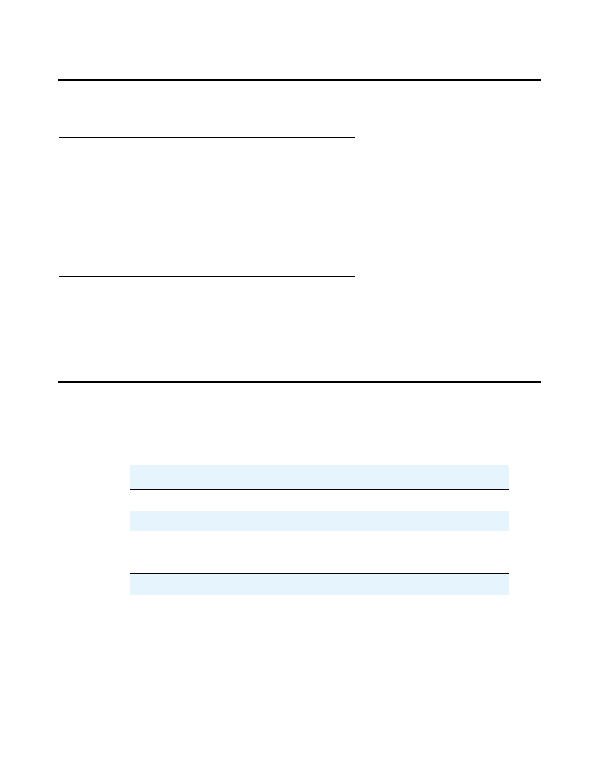
● One Accessory Kit that contains:
One 115V 3 Wire
Power Cable
Note:
Note: Outside the US, the cord must be VDE Certified or Harmonized (HAR), rated 25 0V,
3-conductor (3
rd
wire ground), 1.0 mm2 minimum conductor size.
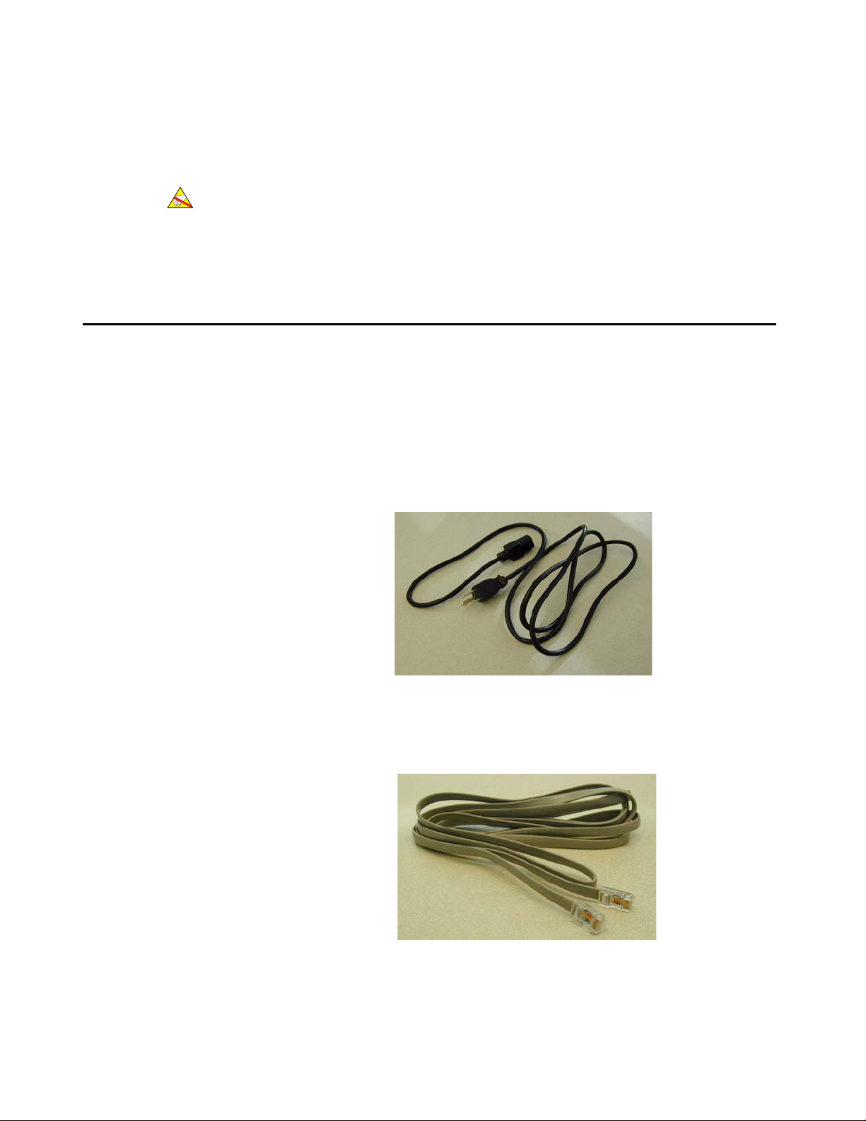
One RJ45 to RJ45
Flat Cable
Issue 3 February 2007 11
Page 12

Unpack the Device
One RJ45 to DB9F
Adapter
One DB25M Adapter
One Grounding
Cable Assembly
Four (4) Rubber
Standoffs
12 Quick Start for Hardware Installation Avaya G250 Media Gateway
Page 13

Two (2) 19"
Rackmount Brackets
One Cable
Management riveting
Assembly
Equipment
Nine (9) 5/16" (8 mm)
Flat-Head Screws
One Bridge for
NVRAM init
Issue 3 February 2007 13
Page 14

Unpack the Device
Documentation
● Release Notes
● Quick Start Guide (this document)
Other Components
Media modules to connect voice and data devices, and out side lines are p ackaged and shipped
in separate boxes. The Avaya Partner Cont act Closure adjunct box, if ordered, is also p ackaged
separately.
14 Quick Start for Hardware Installation Avaya G250 Media Gateway
Page 15

Chapter 3: Mount the Device
You can position the Avaya G250 Media Gateway on a suitable t able, or mount it in a rack or o n
the wall.
Positioning on a Table
To in stall the Avaya G250 Media Gateway as a tabletop unit:
1. Remove the four rubber standoffs from their package.
2. Turn the G250 upside down.
3. Position each foot into one of the mounting sites, near each corner of the chassis.
4. Press the plastic rivet into the foot with a stylus until the rivet is firmly seated on the chassis.
Mounting in a Rack
You can fasten the G250 to a standard 19-inch rack either at the front of the G250 or at its
middle. Attach the mounting brackets to the device before you mount the G250.
Issue 3 February 2007 15
Page 16

Mount the Device
Front mounting bracket placement
Attach a regular mounting bracket to one side of the G250 (refer to Figure 1: Front and Middle
Mounting Bracket Placement on page 16), near the front. You can attach a regular mounting
bracket or a mounting bracket with cable guides to the other side of the G250 (refer to
Figure 2: Attaching a mounting bracket with cable guides
Figure 1: Front and Middle Mounting Bracket Placement
on page 17 for the latter option).
1
Figure notes:
1. Front mounting placement
2. Middle mounting placement
Middle Mounting Bracket Placement
Attach regular mounting brackets to the sides of the G250 (refer to Figure 1: Front and Middle
Mounting Bracket Placement on page 16).
Mounting bracket with cable guide
Attach a mounting bracket with cable guides on one side of the G250, near the front (refer to
Figure 2: Attaching a mounting bracket with cable guides
2
on page 17).
16 Quick Start for Hardware Installation Avaya G250 Media Gateway
Page 17

Figure 2: Attaching a mounting bracket with cable guides
Mounting in a Rack
Attaching Mounting Brackets
Follow these steps to attach the mounting brackets:
1. Position a bracket over the desired mounting position.
2. Affix the bracket to the chassis with three flat-head 5/16" screws.
3. Tighten the screws with the screwdriver.
Mounting the G250
Follow these steps to mount the G250:
1. Position the G250 in the rack. Ensure that there is adequate ventilation.
2. Verify that the screw holes are aligned with the rack hole positions.
3. Insert two mounting screws on each side.
4. Tighten the mounting screws. Do not overtighten the screws.
5. Verify that ventilation vents are not obstructed.
Issue 3 February 2007 17
Page 18

Mount the Device
Mounting on the Wall
To mount the G250 on a wall, use the two mounting brackets without cable guides. If the wall is
flat, you can screw the G250 directly to the wall. If the wall is not flat, screw a 365 x 465 mm
(14.4" x 18.5") plywood board, 20 mm (7/8") thick, to the wall with wood screws. Fasten the
G250 to the plywood board. Affix a bracket to each side of the G250, as shown in Figure 3
Figure 3: Wall mounting bracket placement
.
Note:
Note: Avaya has developed special hardware platforms for customers with harsh
environmental conditions. These platforms were tested to meet strict physical
and environmental requirements imposed by the United States Navy for use on
their ships. The platforms make use of specialized racks and reinforcements.
Customers that want to obtain information about the design and implementation
of such a ruggedized solution can contact Avaya Navy Shipboard Services.
18 Quick Start for Hardware Installation Avaya G250 Media Gateway
Page 19

Chapter 4: Install Media Modules
Install the necessary Media Modules and related components to support the configuration
required for your site. If this Media Gateway needs to function as an ICC or as an LSP, install an
S8300B Media Server module.
Tip:
Tip: If the product is staged, then the media modules are already installed.
Figure 4: The G250 front panel ports and slots
1
9
3
4 5 7 8
10 11 12 13
Figure 5: The G250-BRI front panel ports and slots
1
9
3
4 5 7 86
10 11
2
14
2
14
12
13
Issue 3 February 2007 19
Page 20

Install Media Modules
Figure 6: The G250-DCP front panel ports and slots
1
14
13
3
9
4
5
7 8
10 11
Figure 7: The G250-DS1 front panel ports and slots
1
9
3
4 5 7 8
Figure notes: for Figures 4, 5, 6, and 7
1. V1 - ICC/LSP Slot
2. V2 - WAN (Wide Area Network)
Media Module Slot
3. Analog port LEDs
4. Analog trunk ports
5. Analog line ports
6. ISDN BRI trunk ports (G250-BRI only)
7. System LEDs
8. Console port
10 11
9. USB port
10. CCA (Contact Closure) port
11. WAN port
12. PoE (Power over Ethernet) ports
13. RST (Reset) button
14. ASB (Alternate Software Bank) button
15. DCP ports (G250-DCP only)
16. DCP LEDs
17. T1/E1 ports (G250-DS1 only)
2
12
16
15
2
14
12 1317
Installing an S8300B Media Server Module
Note:
Note: The S8300A is not compatible with the G250. See Identifying the S8300 on
page 21 for information on identifying the S8300 version.
20 Quick Start for Hardware Installation Avaya G250 Media Gateway
Page 21

Identifying the S8300
Figure 8: The S8300B Media Server Module
There are three ways to identify the version of the S8300:
● The S8300B faceplate is grey.
● The S8300B product label contains "AVAYA S8300 ICC/LSP B V1"
● The S8300B has two on-board Dual In-Line Memory Modules (DIMMs): the S8300A has
one.
Note:
Note: You can only insert the S8300B in slot V1 on the left side of the Avaya G250
Media Gateway.
Installing an S8300B Media Server Module
To install an S8300B Media Server Module:
1. Remove the plate labeled "Remove before removing or inserting S8300 module".
2. Remove the blank plate from slot V1.
3. Position the media module squarely before the V1 bay opening and engage both sides of
the module in the interior guides.
4. Slide the S8300B module slowly into the chassis. Maintain an even pressure to ensure that
the module does not become twisted or disengaged from the guides.
Figure 9: Inserting the S8300B media server module.
5. Apply firm pressure to engage the connectors.
6. Tighten the spring-loaded captive screws on the front of the module to lock the S8300B
Media Server module into the chassis.
7. Replace the plate labeled "Remove before removing or inserting S8300 module" above slot
V1. Tighten the screws on the front of the plate.
Issue 3 February 2007 21
Page 22

Install Media Modules
Installing other Media Modules
Supported Modules
The G250 does not support all Media Modules. Before you insert other Media Modules, review
the following list for combination limitations.
The Avaya G250 Media Gateway supports the following modules only:
● S8300B Media Gateway in slot V1
● MM340 in slot V2
● MM342 in slot V2
Inserting Media Modules
Insert the Media Modules needed for your configuration.
Some Media Modules might require additional components.
Media Modules are restricted to slot V2. Ensure that you insert each module in a slot
appropriate for that module. For a list of allowable slots for each Media Module, see Supported
Modules on page 22.
22 Quick Start for Hardware Installation Avaya G250 Media Gateway
Page 23

Chapter 5: Power Up
Grounding Requirements
Note:
Note: Grounding requirements differ widely from country to country. In addition to the
instructions for grounding presented in this section, you must follow the local
electrical installation codes for your location.
You must use two safety grounds to ensure safe operation of the Avaya G250 Media Gateway:
● the ground conductor that is part of the AC power cord.
● the field-installed green/yellow conductor, referred to as the Supplementary Ground
Conductor.
Figure 10: Supplementary Ground Conductor
Both safety grounds must be connected to an approved ground (see Chapter 2 of Installing an d
Upgrading the Avaya G250 Media Gateway, 03-300434, for the definition of an approved
ground). If a power cord accompanies the G250, use that cord whenever possible.
!
WARNING:
WARNING: Connection of both grounds (the AC Power Cord and the Supplementary Ground
Conductor) is required for safe operation of the Avaya G250 Media Gateway.
!
WARNING:
WARNING: An improper ground can cause electrical shock, equipment failures, and service
outages.
Issue 3 February 2007 23
Page 24

Power Up
Connecting Ground Conductors
To attach the ground wires:
1. Remove the ground screw on the rear of the chassis adjacent to the ground symbol.
2. Place the ring terminal of the 14 AWG (1.5 mm
screw.
3. Re-attach the ground screw on the chassis and securely tighten the screw so the screw
cannot be loosened without the use of a tool.
4. Attach the Supplementary Ground Conductor to an approved ground.
Using a Ground Block
A ground block might be provided for use with multiple Media Gateway installations. Usually, the
customer electrician mounts the ground block.
2
) Supplementary Ground Conductor on the
To attach the Supplementary Ground Conductor (that is already attached to the grounding
screw on the chassis) to a ground block:
1. Cut the Supplementary Ground Conductor to the length needed to terminate the conductor
into one of the terminals of the ground block. Do not coil the Supplementary Ground
Conductor.
2. Attach the remaining end of the Supplementary Ground Conductor to a terminal in the
ground block.
3. Cut this ground wire to the length needed to reach the approved ground. Do not coil this
wire.
24 Quick Start for Hardware Installation Avaya G250 Media Gateway
Page 25

Connecting Power
To connect the power:
1. Connect the AC power cable to the inlet receptacle on the rear of the chassis.
2. Connect the other end of the power cable into a mains socket.
LED Sequence
When you turn on the G250, the following LED sequence occurs:
1. The PWR and ALM LEDs on the front panel light.
2. The CPU LED lights up after approximately 15 seconds if the firmware is running.
Connecting Power
Issue 3 February 2007 25
Page 26

Power Up
26 Quick Start for Hardware Installation Avaya G250 Media Gateway
Page 27

Chapter 6: Prepare for Configuration
Before you prepare the G250 for configuration, ensure that you load the completed Electronic
Pre-Installation Worksheet onto the laptop. You should also load any firmware, license, or
authentication files that you have prepared onto the laptop.
Preparations for configuration differ depending on whether your G250 contains an S8300B
Media Server. The following section describes the preparation of a G250 that includes an
S8300B Media Server. If your G250 does not include an S8300B Media Server, skip to
Configuring a G250 without an S8300B Media Server
Preparing a G250 with an S8300B Media Server
You use the Avaya Installation Wizard (AIW) to configure the G250 with an S8300B. If a remote
technician is configuring the G250, see Preparing the G250 with an S8300B for a remote
configuration on page 32.
To prepare the S8300B for configuration:
on page 33.
1. Connect the laptop you prepared to the Services port on the S8300B. Use a standard
Ethernet crossover cable.
2. Configure the network settings on the laptop, according to the following tables:
Table 3: TCP/IP settings
Setting Value
IP Address 192.11.13.5
Subnet Mask 255.255.255.252
DNS disable
WINS Servers do not use (clear out any
values)
Table 4: Internet Explorer Settings
Setting Value
Proxy Server disable
Issue 3 February 2007 27
Page 28

Prepare for Configuration
3. Open Internet Explorer, and browse to 192.11.13.6. The Welcome screen appears.
4. Click Continue on the Welcome screen. The Logon screen appears.
5. Logon on the Logon screen, and click Logon. The main menu for Avaya Integrated
Management appears.
Figure 11: Integrated Management Main Menu
6. Ask a customer representative for a login name and p assword that the customer would like
for the superuser login. If you are a business partner , you can also repeat this procedure to
add the dadmin login.
Note:
Note: Make sure the customer can change this login, its password, or its permissions
later.
7. Under Security, select Administrator Accounts.
The Administrator Accounts screen appears.
28 Quick Start for Hardware Installation Avaya G250 Media Gateway
Page 29

Figure 12: Administrator Accounts screen
Preparing a G250 with an S8300B Media Server
8. Type the login name in the Enter Login ID or Group Name field.
9. Select Add Login, and click Submit.
The Administrator Logins -- Add Login screen appears.
Issue 3 February 2007 29
Page 30

Prepare for Configuration
Figure 13: Administrator Logins -- Add Login screen
10. Type susers in the login group field.
11. Type prof18 in the additional group s field. prof18 is the code for the customer superuser.
12. Select the allow Linux shell access check box.
13. For the select type of authentication option, select password.
14. Complete the following fields:
● enter key or password
● re-enter key or password
30 Quick Start for Hardware Installation Avaya G250 Media Gateway
Page 31

Preparing a G250 with an S8300B Media Server
15. Specify whether to force password/key change on first login.
Note:
Note: Do not lock the account or set the password to be disabled.
16. Leave the defaults in the remaining fields.
17. Click Add.
The system informs that it successfully added the login.
18. From the Integrated Management main menu, select Launch Avaya Inst allation Wizard. The
Avaya Installation Wizard opening screen appears.
To configure the S8300B using the Avaya Installation Wizard:
Step through the pages of the AIW to configure the S8300B and the G250. Take note of the
following items:
1. On the initial AIW page, you can upgrade the wizard if you have a more current version of
the AIW.rpm wizard file. You can download the most current version of the AIW.rpm wizard
file from the Avaya Web site at http://support.avaya.com/avayaiw
2. On the Import EPW page, import the Electronic Pre-Installation Worksheet (EPW) that was
prepared.
.
3. On the Usage Options page, verify the role of this S8300B server.
4. Use the NVRAM Init page to initialize the G250.
5. On the Date/Time page, set the correct date, time, and time zone.
6. If you have a software upgrade file for Co mmunication Manager, use the CM Upgrade page
to select the file and upgrade the software.
7. If you have a software update (patch) file for Communication Manager, use the Software
Update page to select the file and update the software.
8. If you are not using AIW to generate basic translations, select the Translation will be
added after the installation option on the Translation Source page.
9. On the Security Files page, load the License file that you prepared from your laptop.
Note:
Note: If you are using AIW to generate basic translations, initially you load a license file
with the DADMIN feature enabled. At the conclusion of the AIW configuration,
you load a second license file with the DADMIN feature disabled.
10. On the Media Gateway IP Address page, click to configure the G250.
11. On the Firmware page, upgrade G250 and Media Module firmware . New firmware files can
be loaded from your laptop directly into the Media Server /tftpboot directory, if needed.
12. Use the Change Master Key - Optional screen to optionally change the master ke y, which is
used to encrypt gateway secrets (passwords, etc.) in the gateway configuration file.
Issue 3 February 2007 31
Page 32

Prepare for Configuration
13. If you will be using the VPN feature, use the Gateway License screen t o install the gateway
license file.
14. If you have a service contract with Avaya, use the Gateway Authentication screen to install
the gateway authentication file. This file enables secure remote access to the gateway.
15. On the Authentication File page, load the Authentication file that you prepared from your
laptop.
Preparing the G250 with an S8300B for a remote configuration
If you need to prepare the G250 with an S8300B for a remote configuration, you must attach
and enable a modem.
To prepare the G250 with an S8300B for a remote configuration:
1. Connect a USB modem to one of the USB ports on the S8300B Media Server.
2. From the Integrated Management Main Menu select Launch Maintenance Web Interface
(see Figure 11: Integrated Management Main Menu
on page 28).
3. Use the Maintenance Web Pages to enable the modem.
4. To ensure that the modem is enabled correctly, setup a dialup connection on a remote PC
with the following settings:
a. Automatically detect settings.
b. No Username, Password, or Domain.
c. Security > Show Terminal Window.
5. Dial in to the modem from the remote PC.
6. When prompted, provide the rasaccess login and password in the Terminal Window.
7. Close the Terminal Window to complete the connection.
8. A remote technician can now access the S8300B remotely and run AIW. Open Internet
Explorer and browse to 10.3.0.1.
32 Quick Start for Hardware Installation Avaya G250 Media Gateway
Page 33

Configuring a G250 without an S8300B Media Server
Configuring a G250 without an S8300B Media Server
You use the Gateway Installation Wizard (GIW) to configure the Avaya G250 Media Gateway
without an S8300B. Y ou can perform the configuration on site, or prepare the G250 for a remote
configuration.
To configure the G250 using GIW:
1. Install the GIW software on your laptop. You can download the GIW software from the
Avaya support Web site, at http://support.avaya.com/avayaiw/download.html
2. Connect the flat RJ-45 to RJ-45 cable to the DB-9 cable adapter.
3. Plug the RJ-45 cable into the Console port of the G250 (labeled CONSOLE).
4. Plug the DB-9 end of the cable into a COM port of the laptop.
5. Double-click the GIW icon on the laptop to open the Gateway Installation Wizard. The
Overview screen appears.
6. Click Continue. The COM Port Selection screen appears.
.
7. Select the COM port you are using on the laptop to connect to the G250 fro m the COM Port
drop down list.
Note:
Note: Not every COM port works with every laptop. If you have trouble connecting
using the COM port you have selected, try a different COM port.
8. Click Continue. The Wizard Usage Options screen appears.
9. To perform an on site configuration using the GIW, continue with the next section. To
prepare for a remote configuration, continue with Prep aring for a remote configuration of the
G250 on page 34.
To configure the G250 on site:
1. From the Wizard Usage Options screen, select Continue the installation using this
wizard, and click Continue.
2. On the Initialize Components screen, check the options that are appropriate for your
installation.
3. On the Import EPW screen, import the Electronic Pre-Installation Worksheet (EPW) that
was prepared.
Issue 3 February 2007 33
Page 34

Prepare for Configuration
4. Use the IP Address screen to configure addresses and communication parameters for the
G250. Click to configure the following information for the media gateway:
a. Use the PMI screen to specify the details of the Primary Management Interface of the
G250.
b. Use the SNMP screen to specify SNMP community strings and trap destinations.
c. Use the MGC List screen to specify the Media Gateway Controller(s) used to manage the
G250, and the Transition Point information. Click Ping Test to test the accessibility of
each MGC.
5. On the Firmware screen, identify the TFTP server used for file transfer, and specify the
firmware upgrade files to load.
6. Use the Change Master Key - Optional screen to optionally change the master ke y, which is
used to encrypt gateway secrets (passwords, etc.) in the gateway configuration file.
7. If you will be using the VPN feature, use the Gateway License screen t o install the gateway
license file.
8. If you have a service contract with Avaya, use the Gateway Authentication screen to install
the gateway authentication file. This file enables secure remote access to the gateway.
9. Use the G250 Modem Type Selection screen to enable a modem attached to the G250.
10. Use the Change Root Password screen to set the root password for the G250.
11. Click Finish to complete the G250 configuration.
Preparing for a remote configuration of the G250
If you need to prepare the G250 for a remote configuration, you must attach a modem and
enable it using the GIW.
To prepare for a remote configuration:
1. From the Wizard Usage Options screen, select Enable the modem for remote
installation, and click Continue. The Modem Type Selection screen appears.
2. Select the type of modem you are using, and click Continue.
3. Verify that the modem p arameters are correct for the type of modem that you selected. Click
Continue. The Connect Modem screen appears.
4. From the Connect Modem screen, click Finish to exit the Gateway Installation Wizard.
5. Connect the modem that you specified in Step 2.
6. Dial in to the modem to ensure that it is set up correctly.
7. A remote technician can now dial in to the G250 and complete the configuration using the
CLI interface.
34 Quick Start for Hardware Installation Avaya G250 Media Gateway
Page 35

Next Steps
Using AIW and GIW
The full configuration process is performed using the Avaya Installation Wizard or Gateway
Installation Wizard interface. For more detailed information about AIW and GIW:
● See the online help for AIW and GIW at http://support.avaya.com/avayaiw.
● Review Job Aid: Avaya Installation Wizard, 555-245-754, and Job Aid: Avaya Gateway
Installation Wizard, 555-245-756.
Using the Command Line Interface
For information about configuring the G250 with the Command Line Interface:
Next Steps
● For instructions on how to connect to the CLI, review Chapter 3 of Administration for the
Avaya G250 and Avaya G350 Media Gateways, 03-300436, Accessing the Avaya G250/
G350 Media Gateway.
● For detailed information on CLI commands refer to the Avaya G250 and Avaya G350 CLI
Reference, 03-300437.
Issue 3 February 2007 35
Page 36

Prepare for Configuration
36 Quick Start for Hardware Installation Avaya G250 Media Gateway
 Loading...