

Page 1

Avaya Integrated Management
Release 5.0
G250/G350/G450 Manager User Guide
14-300166
Issue 5
October 2007
Page 2

© 2007 Avaya Inc.
All Rights Reserved.
Notice
While reasonable efforts were made to ensure that the infor mation in this
document was complete and accurate at the time of printing, Avaya Inc. can
assume no liability for any errors. Changes and corrections to the information
in this document may be incorporated in future releases.
For full legal page information, please see the complete document, A vaya
Legal Page for Software Documentation, Document number 03-600758.
To locate this document on the website, simply go to
http://www.avaya.com/support
search box.
Documentation disclaimer
Avaya Inc. is not responsible for any modifications, additions, or deletions to
the original published version of this documentation unless such modifications,
additions, or deletions were performed by Avaya. Customer and/or End User
agree to indemnify and hold harmless Avaya, Avaya's agents, servants and
employees against all claims, lawsuits, demands and judgments arising out of,
or in connection with, subsequent modifications, additions or deletions to this
documentation to the extent made by the Customer or End User.
Link disclaimer
Avaya Inc. is not responsible for the contents or reliability of any linked Web
sites referenced elsewhere within this documentation, and Avaya does not
necessarily endorse the products, services, or informa tion described or o ff ered
within them. We cannot guarantee that these links will work all of the time and
we have no control over the availability of the linked pages.
Warranty
Avaya Inc. provides a limited warranty on this product. Refer to your sales
agreement to establish the terms of the limited warran ty. In addition, Avaya’s
standard warranty language, as well as information regarding support for this
product, while under warranty, is available through the following Web site:
http://www.avaya.com/support
Copyright
Except where expressly stated otherwise, the Product is protected by copyrigh t
and other laws respecting proprietary rights. Unauthorized reproduction,
transfer, and or use can be a criminal, as well as a civil, offense un der the
applicable law.
Avaya support
Avaya provides a telephone number for you to use to report pro blems or t o ask
questions about your product. The support telephone number
is 1-800-242-2121 in the United States. For additional support telephone
numbers, see the Avaya Web site:
http://www.avaya.com/support
and search for the document number in the
Page 3

Contents
Preface . . . . . . . . . . . . . . . . . . . . . . . . . . . . . . . . . . 13
The Purpose of This Guide . . . . . . . . . . . . . . . . . . . . . . . . . . . . . . 13
Who Should Use This Guide . . . . . . . . . . . . . . . . . . . . . . . . . . . . . 13
Organization of This Guide . . . . . . . . . . . . . . . . . . . . . . . . . . . . . . 13
Chapter 1: Introduction . . . . . . . . . . . . . . . . . . . . . . . . . . . 17
Avaya G250/G350/G450 Manager Overview . . . . . . . . . . . . . . . . . . . . . 17
Starting the Avaya G250/G350/G450 Manager . . . . . . . . . . . . . . . . . . . . 18
Avaya G250/G350/G450 Device Manager as Part of Avaya Network Management 18
Running Avaya G250/G350/G450 Manager from Avaya Network
Management Console . . . . . . . . . . . . . . . . . . . . . . . . . . . . 18
Avaya G350/G450 Manager via Web Management . . . . . . . . . . . . . . . 18
The User Interface . . . . . . . . . . . . . . . . . . . . . . . . . . . . . . . . . . . 19
Application Tabs. . . . . . . . . . . . . . . . . . . . . . . . . . . . . . . . . . 20
Status Line . . . . . . . . . . . . . . . . . . . . . . . . . . . . . . . . . . . . . 20
Managing Tables. . . . . . . . . . . . . . . . . . . . . . . . . . . . . . . . . . . . 21
Chapter 2: Device Manager . . . . . . . . . . . . . . . . . . . . . . . . . 23
The G250/G350/G450 Device Manager User Interface. . . . . . . . . . . . . . . . 23
Application Toolbar . . . . . . . . . . . . . . . . . . . . . . . . . . . . . . . . 24
Get/Set Toolbar . . . . . . . . . . . . . . . . . . . . . . . . . . . . . . . . . . 25
Tree View. . . . . . . . . . . . . . . . . . . . . . . . . . . . . . . . . . . . . . 27
Desktop. . . . . . . . . . . . . . . . . . . . . . . . . . . . . . . . . . . . . . . 27
Chassis View. . . . . . . . . . . . . . . . . . . . . . . . . . . . . . . . . . . . 27
GBIC Ports . . . . . . . . . . . . . . . . . . . . . . . . . . . . . . . . . . . 30
Selecting Elements . . . . . . . . . . . . . . . . . . . . . . . . . . . . . . 30
Dialog Area. . . . . . . . . . . . . . . . . . . . . . . . . . . . . . . . . . . . . 31
Avaya G250/G350/G450 Modes . . . . . . . . . . . . . . . . . . . . . . . . . . . . 31
Refreshing Device Information . . . . . . . . . . . . . . . . . . . . . . . . . . . . 32
Using Dialog Boxes and Tables. . . . . . . . . . . . . . . . . . . . . . . . . . . . 32
Using Avaya G250/G350/G450 Device Manager Help . . . . . . . . . . . . . . . . 33
Opening the Help to the Contents Page . . . . . . . . . . . . . . . . . . . . . 33
Opening the Help to a Topic of Interest . . . . . . . . . . . . . . . . . . . . . 33
Chapter 3: Device Configuration . . . . . . . . . . . . . . . . . . . . . . 35
Viewing Device Configuration . . . . . . . . . . . . . . . . . . . . . . . . . . . . 35
Device Configuration - General Tab . . . . . . . . . . . . . . . . . . . . . . . 36
Device Configuration - Advanced Tab . . . . . . . . . . . . . . . . . . . . . . 39
Device Configuration - FRU Tab . . . . . . . . . . . . . . . . . . . . . . . . . 41
Issue 5 October 2007 3
Page 4

Contents
Device Configuration - 802.1x Tab . . . . . . . . . . . . . . . . . . . . . . . . 44
Viewing Module Configuration . . . . . . . . . . . . . . . . . . . . . . . . . . . . 45
Module Configuration - General Tab . . . . . . . . . . . . . . . . . . . . . . . 46
Viewing Port Configuration . . . . . . . . . . . . . . . . . . . . . . . . . . . . . . 48
Port Configuration - General Tab . . . . . . . . . . . . . . . . . . . . . . . . . 49
Port Configuration - Advanced Tab . . . . . . . . . . . . . . . . . . . . . . . 52
Port Configuration - 802.1X Tab . . . . . . . . . . . . . . . . . . . . . . . . . 54
Port Configuration - LLDP Tab . . . . . . . . . . . . . . . . . . . . . . . . . . 58
Configuring the External Modem . . . . . . . . . . . . . . . . . . . . . . . . . . . 60
Configuring the Dialer. . . . . . . . . . . . . . . . . . . . . . . . . . . . . . . . . 64
Resetting the Device. . . . . . . . . . . . . . . . . . . . . . . . . . . . . . . . . . 66
Chapter 4: Power over Ethernet . . . . . . . . . . . . . . . . . . . . . . 67
PoE Overview . . . . . . . . . . . . . . . . . . . . . . . . . . . . . . . . . . . . . 67
Viewing PoE Information . . . . . . . . . . . . . . . . . . . . . . . . . . . . . . . 67
Viewing PoE Port Information . . . . . . . . . . . . . . . . . . . . . . . . . . 68
Viewing PoE Configuration . . . . . . . . . . . . . . . . . . . . . . . . . . . . 68
PoE Module Configuration . . . . . . . . . . . . . . . . . . . . . . . . . . 68
PoE Port Configuration . . . . . . . . . . . . . . . . . . . . . . . . . . . . 69
Chapter 5: Media Gateway Functions . . . . . . . . . . . . . . . . . . . 71
Media Gateway Overview . . . . . . . . . . . . . . . . . . . . . . . . . . . . . . . 71
Media Gateway Configuration . . . . . . . . . . . . . . . . . . . . . . . . . . . . 71
Viewing Media Gateway Configuration. . . . . . . . . . . . . . . . . . . . . . 72
MG Config . . . . . . . . . . . . . . . . . . . . . . . . . . . . . . . . . . . 72
MGC Config . . . . . . . . . . . . . . . . . . . . . . . . . . . . . . . . . . 74
Viewing Media Module Configuration . . . . . . . . . . . . . . . . . . . . . . 75
Avaya Site Administration . . . . . . . . . . . . . . . . . . . . . . . . . . . . . . 76
Chapter 6: VoIP Engine Configuration . . . . . . . . . . . . . . . . . . . 77
VoIP Overview . . . . . . . . . . . . . . . . . . . . . . . . . . . . . . . . . . . . . 77
VoIP Resources . . . . . . . . . . . . . . . . . . . . . . . . . . . . . . . . . . 78
VoIP Status. . . . . . . . . . . . . . . . . . . . . . . . . . . . . . . . . . . . . 81
Chapter 7: WAN Configuration . . . . . . . . . . . . . . . . . . . . . . . 85
WAN Overview . . . . . . . . . . . . . . . . . . . . . . . . . . . . . . . . . . . . . 85
WAN Module Configuration . . . . . . . . . . . . . . . . . . . . . . . . . . . . . . 86
E1/T1 Port Configuration . . . . . . . . . . . . . . . . . . . . . . . . . . . . . . . 87
Ethernet LAN Port Configuration. . . . . . . . . . . . . . . . . . . . . . . . . . . 90
4 Avaya Integrated Management Release 4.0.1 Softwa re Update Manager
Page 5

Ethernet LAN Port Configuration - General Tab. . . . . . . . . . . . . . . . . 90
Ethernet LAN Port Configuration - Advanced Tab . . . . . . . . . . . . . . . 93
Ethernet WAN Port Configuration . . . . . . . . . . . . . . . . . . . . . . . . . . 94
Ethernet WAN Port Configuration - General Tab . . . . . . . . . . . . . . . . 95
Ethernet WAN Port Configuration - PPPoE Client Tab . . . . . . . . . . . . . 98
Ethernet WAN Port Configuration - DHCP Client Tab . . . . . . . . . . . . . . 100
Ethernet WAN Port Configuration - Extended Keep Alive Tab . . . . . . . . . 103
Viewing Channel Group Information . . . . . . . . . . . . . . . . . . . . . . . . . 105
Channel Group - PPP Session Information . . . . . . . . . . . . . . . . . . . 105
Channel Group. . . . . . . . . . . . . . . . . . . . . . . . . . . . . . . . . 105
Advanced. . . . . . . . . . . . . . . . . . . . . . . . . . . . . . . . . . . . 107
PPP . . . . . . . . . . . . . . . . . . . . . . . . . . . . . . . . . . . . . . . 108
Channel Group - Frame Relay Information. . . . . . . . . . . . . . . . . . . . 110
Frame Relay . . . . . . . . . . . . . . . . . . . . . . . . . . . . . . . . . . 111
Sub-Interfaces . . . . . . . . . . . . . . . . . . . . . . . . . . . . . . . . . 113
DLCIs . . . . . . . . . . . . . . . . . . . . . . . . . . . . . . . . . . . . . . 116
Managing Channel Groups . . . . . . . . . . . . . . . . . . . . . . . . . . . . . . 119
Viewing the Channel Groups Table. . . . . . . . . . . . . . . . . . . . . . . . 119
Creating, Editing, and Deleting Channel Groups . . . . . . . . . . . . . . . . 120
The Channel Group Wizard . . . . . . . . . . . . . . . . . . . . . . . . . . . . 121
Welcome Screen . . . . . . . . . . . . . . . . . . . . . . . . . . . . . . . . 122
Select Name and Encapsulation Screen . . . . . . . . . . . . . . . . . . . 123
Select E1/T1 Port Screen . . . . . . . . . . . . . . . . . . . . . . . . . . . 124
Select Channels and Speed Screen . . . . . . . . . . . . . . . . . . . . . 125
Confirmation Screen. . . . . . . . . . . . . . . . . . . . . . . . . . . . . . 126
USP Configuration. . . . . . . . . . . . . . . . . . . . . . . . . . . . . . . . . . . 127
USP - PPP Interface . . . . . . . . . . . . . . . . . . . . . . . . . . . . . . . . 127
Serial Port . . . . . . . . . . . . . . . . . . . . . . . . . . . . . . . . . . . 127
Advanced. . . . . . . . . . . . . . . . . . . . . . . . . . . . . . . . . . . . 129
PPP . . . . . . . . . . . . . . . . . . . . . . . . . . . . . . . . . . . . . . . 132
USP - Frame Relay Interface . . . . . . . . . . . . . . . . . . . . . . . . . . . 133
Frame Relay . . . . . . . . . . . . . . . . . . . . . . . . . . . . . . . . . . 134
Sub-Frame-Relays . . . . . . . . . . . . . . . . . . . . . . . . . . . . . . . 136
DLCIs . . . . . . . . . . . . . . . . . . . . . . . . . . . . . . . . . . . . . . 139
Contents
Configuring the ETR Port . . . . . . . . . . . . . . . . . . . . . . . . . . . . . . . 142
The Services Interface. . . . . . . . . . . . . . . . . . . . . . . . . . . . . . . . . 143
Configuring Backup Interfaces . . . . . . . . . . . . . . . . . . . . . . . . . . . . 144
Viewing the Backup Interfaces Table. . . . . . . . . . . . . . . . . . . . . . . 144
The Backup Interface Wizard . . . . . . . . . . . . . . . . . . . . . . . . . . . 145
Welcome Screen . . . . . . . . . . . . . . . . . . . . . . . . . . . . . . . . 146
Issue 5 October 2007 5
Page 6

Contents
Primary Interface Screen . . . . . . . . . . . . . . . . . . . . . . . . . . . 147
Backup Interface Screen . . . . . . . . . . . . . . . . . . . . . . . . . . . 148
Backup Interface Parameters Screen. . . . . . . . . . . . . . . . . . . . . 149
Confirmation Screen. . . . . . . . . . . . . . . . . . . . . . . . . . . . . . 150
Dynamic CAC . . . . . . . . . . . . . . . . . . . . . . . . . . . . . . . . . . . 151
Chapter 8: Embedded Tools . . . . . . . . . . . . . . . . . . . . . . . . 153
Configuring the DHCP Server. . . . . . . . . . . . . . . . . . . . . . . . . . . . . 153
Configuring DHCP . . . . . . . . . . . . . . . . . . . . . . . . . . . . . . . . . 153
Configuring Basic DHCP Options . . . . . . . . . . . . . . . . . . . . . . . . 154
Creating a New DHCP Pool . . . . . . . . . . . . . . . . . . . . . . . . . . . . 155
Configuring DHCP Pool Parameters . . . . . . . . . . . . . . . . . . . . . . . 156
Configuring DHCP Assignment Parameters . . . . . . . . . . . . . . . . . . . 157
Configuring the TFTP Server . . . . . . . . . . . . . . . . . . . . . . . . . . . . . 160
Configuring the Converged Network Analyzer Application. . . . . . . . . . . . . 161
Configuring an External Test Plug . . . . . . . . . . . . . . . . . . . . . . . . 162
Configuring Schedulers . . . . . . . . . . . . . . . . . . . . . . . . . . . . . . 164
Chapter 9: VLANs . . . . . . . . . . . . . . . . . . . . . . . . . . . . . . 165
VLAN Configuration Overview . . . . . . . . . . . . . . . . . . . . . . . . . . . . 165
VLANs Overview . . . . . . . . . . . . . . . . . . . . . . . . . . . . . . . . . . 165
Master VLAN List . . . . . . . . . . . . . . . . . . . . . . . . . . . . . . . . . 166
VLAN Tags . . . . . . . . . . . . . . . . . . . . . . . . . . . . . . . . . . . . . 166
Configuring VLANs . . . . . . . . . . . . . . . . . . . . . . . . . . . . . . . . . . 167
VLAN Tree . . . . . . . . . . . . . . . . . . . . . . . . . . . . . . . . . . . . . 168
Selection List. . . . . . . . . . . . . . . . . . . . . . . . . . . . . . . . . . . . 169
Port Configuration Area . . . . . . . . . . . . . . . . . . . . . . . . . . . . . . 170
Managing VLANs . . . . . . . . . . . . . . . . . . . . . . . . . . . . . . . . . . . 171
Creating VLANs . . . . . . . . . . . . . . . . . . . . . . . . . . . . . . . . . . 172
Renaming VLANs . . . . . . . . . . . . . . . . . . . . . . . . . . . . . . . . . 172
Synchronizing VLAN Names . . . . . . . . . . . . . . . . . . . . . . . . . . . 173
Deleting VLANs . . . . . . . . . . . . . . . . . . . . . . . . . . . . . . . . . . 174
Managing Port VLAN Settings . . . . . . . . . . . . . . . . . . . . . . . . . . . . 175
Selecting Ports. . . . . . . . . . . . . . . . . . . . . . . . . . . . . . . . . . . 175
Viewing Port VLAN Settings . . . . . . . . . . . . . . . . . . . . . . . . . . . 175
Using the Port Configuration Area . . . . . . . . . . . . . . . . . . . . . . . . 176
Configuring VLANs Using Drag-and-Drop . . . . . . . . . . . . . . . . . . . . 176
Updating the Device . . . . . . . . . . . . . . . . . . . . . . . . . . . . . . . . . . 176
6 Avaya Integrated Management Release 4.0.1 Softwa re Update Manager
Page 7

Chapter 10: Port Mirroring . . . . . . . . . . . . . . . . . . . . . . . . . 177
Port Mirroring Overview. . . . . . . . . . . . . . . . . . . . . . . . . . . . . . . . 177
Configuring Port Mirroring . . . . . . . . . . . . . . . . . . . . . . . . . . . . . . 177
The Port Mirroring Wizard. . . . . . . . . . . . . . . . . . . . . . . . . . . . . . . 178
Port Mirroring Wizard - Create Welcome. . . . . . . . . . . . . . . . . . . . . 179
Port Mirroring Wizard - Edit/Delete Welcome . . . . . . . . . . . . . . . . . . 180
Port Mirroring Wizard - Source Port Selection. . . . . . . . . . . . . . . . . . 181
Port Mirroring Wizard - Destination Port Selection . . . . . . . . . . . . . . . 182
Port Mirroring Wizard - Frames Direction Selection. . . . . . . . . . . . . . . 183
Port Mirroring Wizard - Confirmation. . . . . . . . . . . . . . . . . . . . . . . 184
Chapter 11: Port RMON . . . . . . . . . . . . . . . . . . . . . . . . . . . 185
Displaying the Port RMON Window . . . . . . . . . . . . . . . . . . . . . . . . . 185
The Pie Chart. . . . . . . . . . . . . . . . . . . . . . . . . . . . . . . . . . . . 186
The Traffic Graph . . . . . . . . . . . . . . . . . . . . . . . . . . . . . . . . . 186
Viewing Traffic Statistics . . . . . . . . . . . . . . . . . . . . . . . . . . . 186
Zooming In and Out of the Graph. . . . . . . . . . . . . . . . . . . . . . . 186
Scrolling within the Graph . . . . . . . . . . . . . . . . . . . . . . . . . . 187
Unfreezing the Graph . . . . . . . . . . . . . . . . . . . . . . . . . . . . . 187
Traffic Types . . . . . . . . . . . . . . . . . . . . . . . . . . . . . . . . . . . . 187
Contents
Chapter 12: Switch Connected Addresses . . . . . . . . . . . . . . . . 189
Switch Connected Addresses Overview . . . . . . . . . . . . . . . . . . . . . . . 189
Viewing the Switch Connected Addresses Window. . . . . . . . . . . . . . . . . 189
Sorting the List of Stations . . . . . . . . . . . . . . . . . . . . . . . . . . . . 191
Chapter 13: Port Redundancy . . . . . . . . . . . . . . . . . . . . . . . 193
Overview of Port Redundancy . . . . . . . . . . . . . . . . . . . . . . . . . . . . 193
Configuring Port Redundancy . . . . . . . . . . . . . . . . . . . . . . . . . . . . 194
Adding a Port Redundancy . . . . . . . . . . . . . . . . . . . . . . . . . . . . . . 195
Port Redundancy Wizard . . . . . . . . . . . . . . . . . . . . . . . . . . . . . . . 196
Port Redundancy Wizard - Welcome . . . . . . . . . . . . . . . . . . . . . . . 197
Port Redundancy Wizard - Primary Port Selection . . . . . . . . . . . . . . . 198
Port Redundancy Wizard - Secondary Port Selection. . . . . . . . . . . . . . 199
Port Redundancy Wizard - Name and Type . . . . . . . . . . . . . . . . . . . 200
Port Redundancy Wizard - Confirmation. . . . . . . . . . . . . . . . . . . . . 201
Deleting Port Redundancies . . . . . . . . . . . . . . . . . . . . . . . . . . . . . 202
Updating the Device . . . . . . . . . . . . . . . . . . . . . . . . . . . . . . . . . . 202
Issue 5 October 2007 7
Page 8

Contents
Chapter 14: Trap Managers Configuration. . . . . . . . . . . . . . . . . 203
Trap Manager Overview . . . . . . . . . . . . . . . . . . . . . . . . . . . . . . . . 203
Configuring Trap Managers. . . . . . . . . . . . . . . . . . . . . . . . . . . . . . 204
Editing the Trap Managers Table . . . . . . . . . . . . . . . . . . . . . . . . . . . 206
Chapter 15: Routing Manager . . . . . . . . . . . . . . . . . . . . . . . 207
TheRouting Manager User Interface . . . . . . . . . . . . . . . . . . . . . . . . . 207
Toolbar . . . . . . . . . . . . . . . . . . . . . . . . . . . . . . . . . . . . . . . 208
Tree View. . . . . . . . . . . . . . . . . . . . . . . . . . . . . . . . . . . . . . 209
Table/Form Area . . . . . . . . . . . . . . . . . . . . . . . . . . . . . . . . . . 210
Editing Tables . . . . . . . . . . . . . . . . . . . . . . . . . . . . . . . . . . . . . 210
Creating New Table Entries . . . . . . . . . . . . . . . . . . . . . . . . . . 211
Modifying Table Entries . . . . . . . . . . . . . . . . . . . . . . . . . . . . 211
Deleting Table Entries . . . . . . . . . . . . . . . . . . . . . . . . . . . . . 211
Saving Table Information in a File . . . . . . . . . . . . . . . . . . . . . . . . . . 211
Saving Configuration Changes . . . . . . . . . . . . . . . . . . . . . . . . . . . . 212
Running Changes . . . . . . . . . . . . . . . . . . . . . . . . . . . . . . . . . 212
Committed Changes. . . . . . . . . . . . . . . . . . . . . . . . . . . . . . . . 212
Resetting a Router. . . . . . . . . . . . . . . . . . . . . . . . . . . . . . . . . . . 212
Using Avaya G250/G350/G450 Routing Manager Help . . . . . . . . . . . . . . . 213
Opening the Help to the Contents Page . . . . . . . . . . . . . . . . . . . . . 213
Opening the Help to a Topic of Interest . . . . . . . . . . . . . . . . . . . . . 213
Chapter 16: Layer 2 . . . . . . . . . . . . . . . . . . . . . . . . . . . . . 215
Layer 2 Interfaces . . . . . . . . . . . . . . . . . . . . . . . . . . . . . . . . . . . 215
Chapter 17: IP Route . . . . . . . . . . . . . . . . . . . . . . . . . . . . 217
Displaying IP Global Parameters . . . . . . . . . . . . . . . . . . . . . . . . . . . 218
Configuring IP Interfaces . . . . . . . . . . . . . . . . . . . . . . . . . . . . . . . 219
Viewing the Dynamic IP Interfaces Table . . . . . . . . . . . . . . . . . . . . . . 222
Viewing the Routing Table . . . . . . . . . . . . . . . . . . . . . . . . . . . . . . 223
Viewing the Static Routing Table . . . . . . . . . . . . . . . . . . . . . . . . . . . 226
Viewing the ARP Table . . . . . . . . . . . . . . . . . . . . . . . . . . . . . . . . 228
Configuring GRE Tunneling. . . . . . . . . . . . . . . . . . . . . . . . . . . . . . 230
DHCP . . . . . . . . . . . . . . . . . . . . . . . . . . . . . . . . . . . . . . . . . . 233
Viewing DHCP/BOOTP Global Parameters. . . . . . . . . . . . . . . . . . . . 233
Configuring DHCP/BOOTP Parameters . . . . . . . . . . . . . . . . . . . . . 234
RIP . . . . . . . . . . . . . . . . . . . . . . . . . . . . . . . . . . . . . . . . . . . 235
8 Avaya Integrated Management Release 4.0.1 Softwa re Update Manager
Page 9

Viewing RIP Global Parameters. . . . . . . . . . . . . . . . . . . . . . . . . . 235
Configuring RIP Interfaces . . . . . . . . . . . . . . . . . . . . . . . . . . . . 236
OSPF . . . . . . . . . . . . . . . . . . . . . . . . . . . . . . . . . . . . . . . . . . 238
Viewing OSPF Global Parameters . . . . . . . . . . . . . . . . . . . . . . . . 239
Configuring OSPF Interfaces . . . . . . . . . . . . . . . . . . . . . . . . . . . 240
Configuring OSPF Area Parameters . . . . . . . . . . . . . . . . . . . . . . . 242
Viewing the OSPF Link State Database . . . . . . . . . . . . . . . . . . . . . 243
Viewing the OSPF External Database . . . . . . . . . . . . . . . . . . . . . . 245
Viewing OSPF Neighbors . . . . . . . . . . . . . . . . . . . . . . . . . . . . . 246
VRRP . . . . . . . . . . . . . . . . . . . . . . . . . . . . . . . . . . . . . . . . . . 247
Viewing VRRP Global Parameters . . . . . . . . . . . . . . . . . . . . . . . . 247
Viewing the VRRP Table. . . . . . . . . . . . . . . . . . . . . . . . . . . . . . 248
Header Compression . . . . . . . . . . . . . . . . . . . . . . . . . . . . . . . . . 250
Configuring cRTP Interfaces . . . . . . . . . . . . . . . . . . . . . . . . . . . 250
Configuring TCP Header Compression Interfaces . . . . . . . . . . . . . . . 251
Chapter 18: Policy Based Routing Manager. . . . . . . . . . . . . . . . 253
Contents
The Policy Based Routing Manager User Interface . . . . . . . . . . . . . . . . . 253
Toolbar . . . . . . . . . . . . . . . . . . . . . . . . . . . . . . . . . . . . . . . 254
Tree View. . . . . . . . . . . . . . . . . . . . . . . . . . . . . . . . . . . . . . 255
Table View . . . . . . . . . . . . . . . . . . . . . . . . . . . . . . . . . . . . . 255
The Application Editor Tool. . . . . . . . . . . . . . . . . . . . . . . . . . . . . . 255
Saving Configuration Changes . . . . . . . . . . . . . . . . . . . . . . . . . . . . 255
Applied Changes. . . . . . . . . . . . . . . . . . . . . . . . . . . . . . . . . . 256
Committed Changes. . . . . . . . . . . . . . . . . . . . . . . . . . . . . . . . 256
Using Avaya G250/G350/G450 Policy Based Routing Manager Help. . . . . . . . 256
Opening the Help to the Contents Page . . . . . . . . . . . . . . . . . . . . . 256
Opening the Help to a Topic of Interest . . . . . . . . . . . . . . . . . . . . . 256
Chapter 19: Policy Based Routing . . . . . . . . . . . . . . . . . . . . . 257
Policy Based Routing Overview . . . . . . . . . . . . . . . . . . . . . . . . . . . 257
Using the Tree View . . . . . . . . . . . . . . . . . . . . . . . . . . . . . . . . . . 258
Using the Table View . . . . . . . . . . . . . . . . . . . . . . . . . . . . . . . . . 258
Policy Based Routing List. . . . . . . . . . . . . . . . . . . . . . . . . . . . . 259
Adding Policies . . . . . . . . . . . . . . . . . . . . . . . . . . . . . . . . 260
Deleting Policies . . . . . . . . . . . . . . . . . . . . . . . . . . . . . . . . 260
Policy Based Routing Rules List . . . . . . . . . . . . . . . . . . . . . . . . . 260
Adding Rules. . . . . . . . . . . . . . . . . . . . . . . . . . . . . . . . . . 264
Modifying Rules . . . . . . . . . . . . . . . . . . . . . . . . . . . . . . . . 264
Issue 5 October 2007 9
Page 10

Contents
Copying Rules . . . . . . . . . . . . . . . . . . . . . . . . . . . . . . . . . 264
Moving Rules. . . . . . . . . . . . . . . . . . . . . . . . . . . . . . . . . . 265
Deleting Rules . . . . . . . . . . . . . . . . . . . . . . . . . . . . . . . . . 265
Next Hop List. . . . . . . . . . . . . . . . . . . . . . . . . . . . . . . . . . . . 265
Adding Routes . . . . . . . . . . . . . . . . . . . . . . . . . . . . . . . . . 266
Modifying Routes . . . . . . . . . . . . . . . . . . . . . . . . . . . . . . . 267
Copying Routes . . . . . . . . . . . . . . . . . . . . . . . . . . . . . . . . 267
Moving Routes . . . . . . . . . . . . . . . . . . . . . . . . . . . . . . . . . 267
Deleting Routes . . . . . . . . . . . . . . . . . . . . . . . . . . . . . . . . 268
Policy Enforcement Points . . . . . . . . . . . . . . . . . . . . . . . . . . . . 268
Configuration . . . . . . . . . . . . . . . . . . . . . . . . . . . . . . . . . . . 269
Policy Based Routing List Configuration . . . . . . . . . . . . . . . . . . 269
Next Hop List Configuration . . . . . . . . . . . . . . . . . . . . . . . . . 271
Using Address Wildcards . . . . . . . . . . . . . . . . . . . . . . . . . . . . . . . 272
Using the IP Simulate Function. . . . . . . . . . . . . . . . . . . . . . . . . . . . 272
IP Simulate Overview . . . . . . . . . . . . . . . . . . . . . . . . . . . . . . . 272
Using IP Simulate . . . . . . . . . . . . . . . . . . . . . . . . . . . . . . . . . 273
Chapter 20: Applications Editor Tool . . . . . . . . . . . . . . . . . . . 277
Applications Editor Overview. . . . . . . . . . . . . . . . . . . . . . . . . . . . . 277
Using the Applications Editor. . . . . . . . . . . . . . . . . . . . . . . . . . . . . 277
Adding Application Protocols . . . . . . . . . . . . . . . . . . . . . . . . . . 279
Modifying an Application Protocol . . . . . . . . . . . . . . . . . . . . . . . . 279
Deleting an Application Protocol . . . . . . . . . . . . . . . . . . . . . . . . . 279
Applying Changes . . . . . . . . . . . . . . . . . . . . . . . . . . . . . . . . . 279
Reports . . . . . . . . . . . . . . . . . . . . . . . . . . . . . . . . . . . . . . . . . 280
Appendix A: Menus . . . . . . . . . . . . . . . . . . . . . . . . . . . . . 281
Device Manager Menus . . . . . . . . . . . . . . . . . . . . . . . . . . . . . . . . 281
File Menu . . . . . . . . . . . . . . . . . . . . . . . . . . . . . . . . . . . . . . 282
View Menu . . . . . . . . . . . . . . . . . . . . . . . . . . . . . . . . . . . . . 282
Configure Menu . . . . . . . . . . . . . . . . . . . . . . . . . . . . . . . . . . 282
Actions Menu . . . . . . . . . . . . . . . . . . . . . . . . . . . . . . . . . . . 284
Tools Menu. . . . . . . . . . . . . . . . . . . . . . . . . . . . . . . . . . . . . 284
Help Menu . . . . . . . . . . . . . . . . . . . . . . . . . . . . . . . . . . . . . 285
Routing Manager Menus . . . . . . . . . . . . . . . . . . . . . . . . . . . . . . . 285
File Menu . . . . . . . . . . . . . . . . . . . . . . . . . . . . . . . . . . . . . . 285
Edit Menu. . . . . . . . . . . . . . . . . . . . . . . . . . . . . . . . . . . . . . 286
View Menu . . . . . . . . . . . . . . . . . . . . . . . . . . . . . . . . . . . . . 286
Action Menu . . . . . . . . . . . . . . . . . . . . . . . . . . . . . . . . . . . . 286
10 Avaya Integrated Management Release 4.0.1 Software Update Manager
Page 11

Help Menu . . . . . . . . . . . . . . . . . . . . . . . . . . . . . . . . . . . . . 287
Policy Based Routing Menus . . . . . . . . . . . . . . . . . . . . . . . . . . . . . 287
File Menu . . . . . . . . . . . . . . . . . . . . . . . . . . . . . . . . . . . . . . 287
Edit Menu. . . . . . . . . . . . . . . . . . . . . . . . . . . . . . . . . . . . . . 288
View Menu . . . . . . . . . . . . . . . . . . . . . . . . . . . . . . . . . . . . . 288
Tools Menu. . . . . . . . . . . . . . . . . . . . . . . . . . . . . . . . . . . . . 288
Help Menu . . . . . . . . . . . . . . . . . . . . . . . . . . . . . . . . . . . . . 289
Applications Editor Menus . . . . . . . . . . . . . . . . . . . . . . . . . . . . . . 289
File Menu . . . . . . . . . . . . . . . . . . . . . . . . . . . . . . . . . . . . . . 289
Edit Menu. . . . . . . . . . . . . . . . . . . . . . . . . . . . . . . . . . . . . . 290
Help Menu . . . . . . . . . . . . . . . . . . . . . . . . . . . . . . . . . . . . . 290
Appendix B: Web Management. . . . . . . . . . . . . . . . . . . . . . . 291
Web Management Overview . . . . . . . . . . . . . . . . . . . . . . . . . . . . . 291
Configuring the Avaya G350/G450 Device . . . . . . . . . . . . . . . . . . . . . . 291
Appendix C: ICMP Packet Types & Codes. . . . . . . . . . . . . . . . . 293
Contents
ICMP Packet Type/Code List . . . . . . . . . . . . . . . . . . . . . . . . . . . . . 293
Index . . . . . . . . . . . . . . . . . . . . . . . . . . . . . . . . . . 297
Issue 5 October 2007 11
Page 12

Contents
12 Avaya Integrated Management Release 4.0.1 Software Update Manager
Page 13

Preface
Welcome to Avaya G250/G350/G450 Manager. This chapter provides an introduction to the
structure and assumptions of this guide. It includes the following sections:
● The Purpose of This Guide - A description of the goals of this guide.
● Who Should Use This Guide - The intended audience of this guide.
● Organization of This Guide - A brief description of the subjects contained in the various
sections of this guide.
The Purpose of This Guide
The Avaya G250/G350/G450 Manager guide contains information needed to use the
management system efficiently and effectively.
Who Should Use This Guide
This guide is intended for network managers familiar with network management and its
fundamental concepts.
Organization of This Guide
This guide is structured to reflect the following conceptual divisions
● Avaya G250/G350/G450 Manager - Information pertaining to the entire Avaya G250/
G350/G450 Manager application and all of its aspects.
● Preface - This section describes the guide’s purpose, intended audience and
organization.
● Introduction - An introduction to the Avaya G250/G350/G450 Manager, including
instructions on starting the Avaya G250/G350/G450 Manager.
● Avaya G250/G350/G450 Device Manager - Information pertaining to Avaya G250/G350/
G450 Device Management.
Issue 5 October 2007 13
Page 14

Preface
● Device Manager - An introduction to the Avaya G250/G350/G450 Device Manager,
including a description of the user interface.
● Device Configuration - Viewing and modifying the different device configurations.
● Power over Ethernet - An overview of Power over Ethernet (PoE) and instructions on
viewing and configuring PoE parameters.
● Media Gateway Functions - An overview of the Media Gateway functions and
information on viewing and configuring Media Gateway components.
● VoIP Engine Configuration - An overview of VoIP Engine functionality and information
on viewing and configuring VoIP Engine parameters.
● WAN Configuration - An overview of and information on viewing and configuring WAN
parameters.
● Embedded Tools - An overview of and information on configuring the Avaya G250/
G350/G450’s embedded server functions and tools.
● VLANs - Viewing and editing VLAN information.
● Port Mirroring - Configuring port mirroring for ports on an Avaya G250/G350/G450
device.
● Port RMON - Viewing graphical representations of the traffic on the ports of the Avaya
G250/G350/G450 device.
● Port Redundancy - Configuring port redundancy for ports on an Avaya G350 or
G450device.
● Switch-Connected Addresses - Viewing information on addresses connected to the
device.
● Trap Manag ers Configuration - Viewing and modifying the Trap Managers table.
● Avaya G250/G350/G450 Routing Manager - Information pertaining to Avaya G250/G350/
G450 routing management.
● Routing Manager - An introduction to configuring routing and a description of the
Avaya G250/G350/G450 Routing Manager user interface.
● Layer 2 - Detailed descriptions of layer 2 configuration that enable you to view layer 2
interfaces at the management station.
● IP Route - Detailed descriptions of IP route configuration that enable you to display and
update IP interfaces, the IP routing table, the ARP table, GRE tunneling parameters,
DHCP/BOOTP parameters, RIP interfaces, OSPF interfaces, area parameters, link-state
database and neighbors, the IP access control table, and redundancy parameters.
● Avaya G250/G350/G450 Policy Based Routing Manager - Information pertaining to
Avaya G250/G350/G450 Policy Based Routing management.
● Policy Based Routing Manager - An introduction to configuring Policy Based Routing
and a description of the Avaya G250/G350/G450 Policy Based Routing Manager user
interface.
14 Avaya Integrated Management Release 4.0.1 Software Update Manager
Page 15

Organization of This Guide
● Policy Based Routing - Detailed descriptions of Policy Based Routing conf iguration that
enable you to display and update Policy Based Routing lists, Next Hop routing tables,
and Policy Enforcement Points.
● Applications Editor Tool - Detailed description of the Applications Editor Tool, which
enables you to refine protocol traffic through Policy Based Routing by customizing
individual protocols.
● Appendices - Additional information about the Avaya G250/G350/G450 Manager.
● Menus - The full structure of the menus in the Avaya G250/G350/G450 Manager.
● Web Management - Instructions on how to manage Avaya G350 and G450 devices via
the Internet.
● ICMP Packet Types and Codes - A list of ICMP Packet Types and Codes as used in IP
SImulate.
Issue 5 October 2007 15
Page 16

Preface
16 Avaya Integrated Management Release 4.0.1 Software Update Manager
Page 17

Chapter 1: Introduction
This chapter provides an introduction to the Avaya G250/G350/G450 Manager. It includes the
following sections:
● Avaya G250/G350/G450 Manager Overview - An overview explaining the different aspects
of Avaya G250/G350/G450 Device management.
● Starting the Avaya G250/G350/G450 Manager - Instructions on how to access
Avaya G250/G350/G450 Manager from your management platform.
● The User Interface - Detailed descriptions of the user interface common to all applications
in the Avaya G250/G350/G450 Manager.
● Managing Tables - An explanation of the symbols used to label table rows.
Avaya G250/G350/G450 Manager Overview
The Avaya G250/G350/G450 Manager provides full management capabilities for Avaya G450,
Avaya G350, and all G250 Devices. This includes the ability to view three aspects of device
management:
● Device Manager - Provides a view of the configuration of the device, including VLAN
configuration, port redundancy, port mirroring, switch connected addresses and traps. For
more information refer to chapters 2-14.
● Routing Manager - Provides a view of the Layer 3 routing and forwarding functions of the
device. For more information refer to
● Policy Based Routing Manager - Provides a view of the configuration and maintenance
chapters 15-17
.
of Policy Based Routing on the Avaya G250/G350/G450 device. For information, refer to
chapters 18-19.
For information on switching between the different views, refer to “Application Tabs” on page 20
.
Issue 5 October 2007 17
Page 18

Introduction
Note:
Starting the Avaya G250/G350/G450 Manager
This section provides instructions for starting Avaya G250/G350/G450 Manager.
Avaya G250/G350/G450 Device Manager as Part of Avaya Network Management
If you installed the Avaya G250/G350/G450 Device Manager as part of Avaya Network
Management, the following sections provide instructions for starting Avaya G250/G350/G450
Manager.
Running Avaya G250/G350/G450 Manager from Avaya Network Management Console
From the management platform map:
1. Select the label representing the Avaya G250/G350/G450 Device you want to manage.
2. Click .
Or
Double-click the Avaya G250/G350/G450 Device.
Or
Select Tools > Avaya Device Manager.
Avaya G350/G450 Manager via Web Management
Note: The Avaya G250 Device does not support web management.
To start Avaya G350/G450 Web Management:
1. Point your web browser to http://xxx.xxx.xxx.xxx, where xxx.xxx.xxx.xxx is the
IP address of the Avaya G350/G450 Device you want to manage. The Enter Network
Password dialog box opens.
18 Avaya Integrated Management Release 4.0.1 Software Update Manager
Page 19

The User Interface
Note:
Figure 1: Enter Network Password Dialog Box
2. Select the desired SNMP mode of operation.
If SNMPv1 is selected, enter the correct SNMPv1 community string in the Community field.
Or
If SNMPv3 is selected, enter a valid username from the SNMPv3 username list and
corresponding authentication and privacy passwords.
Note: Some operations in the Avaya G250/G350/G450 Manager require SNMPv3
authentication credentials. Verify that you are an SNMPv3 user or use the SAA
application. You can use the CLI to create users on the media gateway.
3. Click OK. The Avaya G350/G450 Welcome page opens.
If the required Java plug-in is installed on your computer, the Java Plug-in Security Warning
dialog box opens after a few seconds.
If the required Java plug-in is not installed, the plug-in is automatically downloaded to your
computer. Follow the instructions on the Avaya G350/G450 Welcome page to install the
plug-in.
The User Interface
The Avaya G250/G350/G450 Manager user interface is different for each of its management
applications. However, the following elements of the user interface are common to all views:
● Application Tabs - Tabs for accessing the Device Manager, Policy Based Routing
Manager, and Routing Manager applications for the Avaya G250/G350/G450 Device.
● Application Area - An area where the selected application opens.
● Status Line - Displays the communication status between the Avaya G250/G350/G450
Manager and the Avaya G250/G350/G450 Device.
Issue 5 October 2007 19
Page 20
Introduction
Application Tabs
You can access the three main components of device management using the following
Application Tabs in the Avaya G250/G350/G450 Manager:
● Device Manager - View the Avaya G250/G350/G450 Device Manager for device
configuration and Port RMON.
● Policy Based Routing Manager - View the Policy Based Routing and Next Hop Routing
configuration for the device.
● Routing Manager - View the Avaya G250/G350/G450 Routing configuration.
To switch to a different view, click the appropriate Application Tab. The selected application
opens.
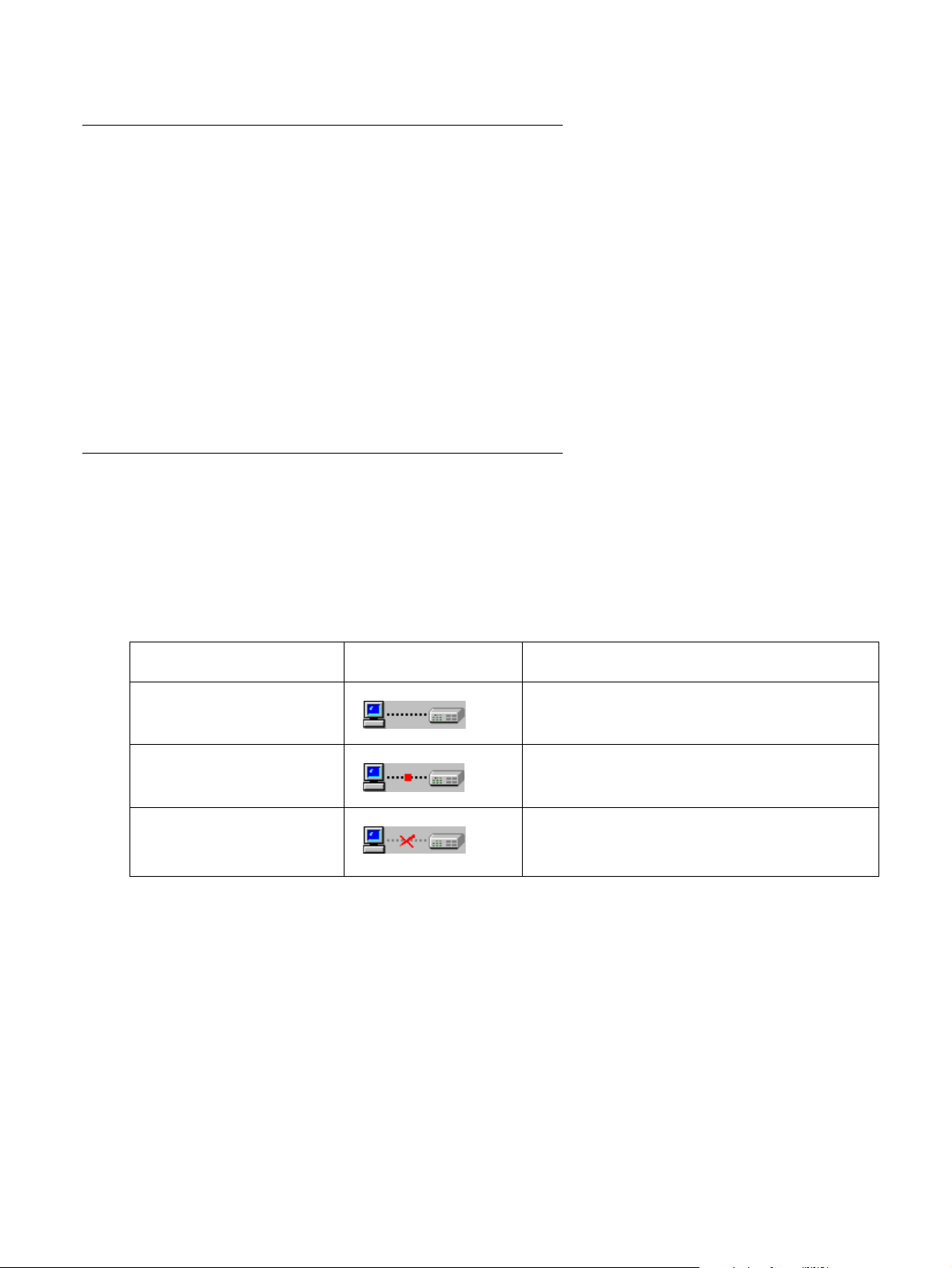
Status Line
The Status Line shows the communication status between the application and the Avaya G250/
G350/G450 Device. The Status Line displays a status message and an appropriate graphic.
The table below shows the possible statuses with the ir corresponding graphics, and provides an
explanation for each status.
Table 1: Communication Statuses
Status Graphic Description
Ready The application is ready to communicate
with the Avaya G250/G350/G450 Device.
Communicating The application is currently communicating
with the Avaya G250/G350/G450 Device.
Communication Error The last attempted communication with the
Avaya G250/G350/G450 Device was not
successful.
20 Avaya Integrated Management Release 4.0.1 Software Update Manager
Page 21
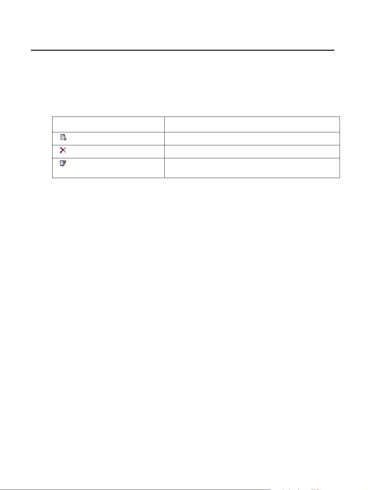
Managing Tables
The Avaya G250/G350/G450 Manager interface displays the status of each row in a table. The
following table shows a list of symbols that can appear at the start of a table row, with their
corresponding explanations.
Table 2: Table Symbols
Symbol Explanation
To undo all the changes made to a table, click Refresh. To undo changes made to a selected
row, click Undo. When all changes are finalized, click Apply to update the device.
Managing Tables
The row is a new entry.
The row is to be deleted.
The information in the row has been changed by the
user.
Issue 5 October 2007 21
Page 22

Introduction
22 Avaya Integrated Management Release 4.0.1 Software Update Manager
Page 23

Chapter 2: Device Manager
This chapter provides an introduction to the Avaya G250/G350/G450 Device Manager. It
includes the following sections:
● The G250/G350/G450 Device Manager User Interface - An introduction to the Avaya
G250/G350/G450 Device Manager user interface, including instructions for selecting
elements and using the toolbar buttons.
● Avaya G250/G350/G450 Modes - Instructions on switching between the configuration and
Port RMON modes in the Avaya G250/G350/G450 Device Manager.
● Refreshing Device Information - Instructions on how to refresh the information in the Avaya
G250/G350/G450 Manager.
● Using Dialog Boxes and Tables - An explanation of the icons found in the dialog boxes and
tables in the Avaya G250/G350/G450 Device Manager.
● Using Avaya G250/G350/G450 Device Manager Help - An explanation of the options for
accessing on-line help in the Avaya G250/G350/G450 Device Manager.
The G250/G350/G450 Device Manager User Interface
The Avaya G250/G350/G450 Device Manager user interface consists of the following elements:
● Application Tabs - Tabs for toggling between Avaya G250/G350/G450 Manager functions
(Device Manager, Routing Manager, Policy-Based Routing Manager).
● Menu Bar - Menus for accessing Avaya G250/G350/G450 Device management functions.
For more information, refer to Appendix A: Menus.
● Application Toolbar - Toolbar buttons for accessing Avaya G250/G350/G450 Device
management functions.
● Get/Set Toolbar - Toolbar buttons for viewing and changing the configuration of ports.
● Tree View - A resizeable window containing a hierarchical representation of the modules
and ports of the Avaya G250/G350/G450 Device.
● Chassis View - A graphical representation of the Avaya G250/G350/G450 Device.
● Dialog Area - A resizeable window where all dialog boxes and tables first open.
For information on other parts of the user interface, refer to “The User Interface” on page 19
.
Issue 5 October 2007 23
Page 24
Device Manager
Application
Tabs
Menu
Bar
Application
Toolbar
Tree
View
Get/Set
Toolbar
Chassis
View
Dialog
Area
Status
Line
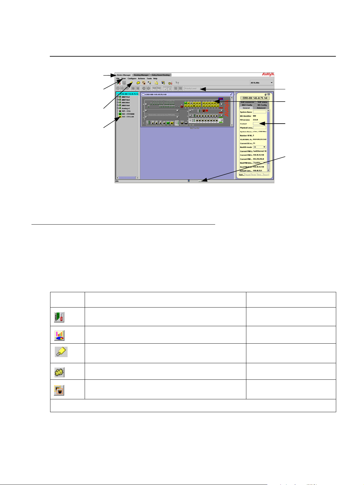
The figure below shows the user interface, with its various parts labeled.
Figure 2: The Avaya G250/G350/G450 Device Manager User Interface
To resize the three main areas of the user interface, the Tree View, the Chassis View, and the
Dialog Area, use the splitter bars and their arrows.
Application Toolbar
The Application Toolbar provides shortcuts to the main Device Manager functions.
The table below describes the buttons on the Application Toolbar and gives the equivalent
menu options.
Table 3: Application Toolbar
Button Description Menu Item
Sets the Device Manager to Configuration Mode. View > Configuration
Sets the Device Manager to Port RMON mode. View > Port RMON
Shows Switch-Connected Addresses. View > Switch-Connected
Displays the VLAN window. Configure > VLAN
Displays the Port Redundancy table. Configure > Port
Addresses
Redundancy
1 of 2
24 Avaya Integrated Management Release 4.0.1 Software Update Manager
Page 25
The G250/G350/G450 Device Manager User Interface
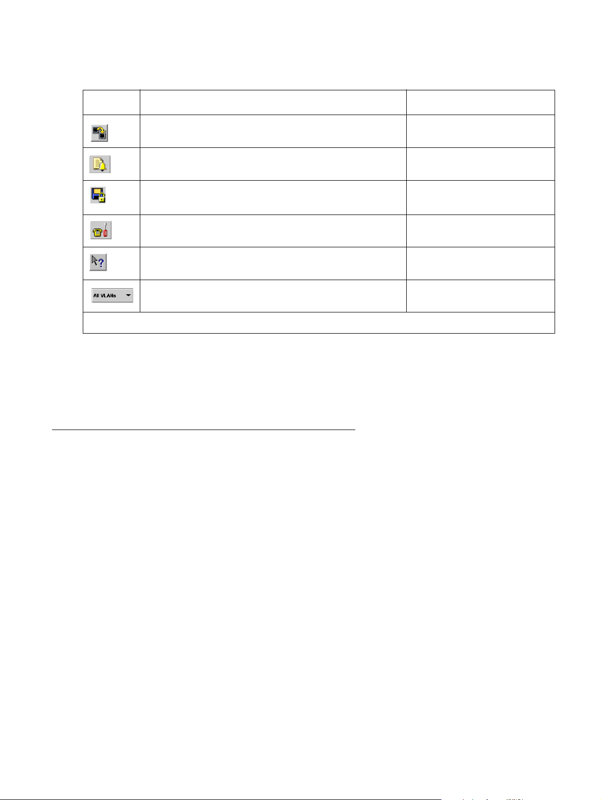
Table 3: Application Toolbar (continued)
Button Description Menu Item
Starts the Port Mirroring wizard. Configure > Port
Mirroring
Displays the Trap Manager Table. Configure > Trap
Managers
Commits configuration changes. Actions > Commit
Launches Avaya Call Processing on the selected
Media Gateway or Voice port.
Opens the on-line help. Help > Help On
Selects a VLAN. Ports that are not on the selected
VLAN appear dark gray in the Chassis View.
When you place the cursor on a toolbar icon for one second, a label appears with the name of
the button.
You can toggle the display of the application toolbar. To toggle the display of the application
toolbar, select View > Toolbars > Show Application Toolbar.
Get/Set Toolbar
The Get/Set Toolbar provides buttons for getting and setting configuration parameters for
selected ports. When a port is selected, its configuration is reflected on the Get/Set Toolbar.
Each group of buttons represents the various possible states of a configuration parameter. For
example, the first group of buttons represents the possible speed of a port - 10 Mbps,
100 Mbps, or 1000 Mbps. If the center button is depressed, the port is currently configured to
operate at 100 Mbps.
Tools > Administer
Station/Gateway
2 of 2
Selected ports can be configured using the Get/Set Toolbar. To change the configuration of a
port, click the button that represents the value of the parameter you want to apply to the port.
Click apply to update the device with the changes. Click cancel to discard the changes.
Options not applicable to the selected port are greyed out.
Multiple ports can be simultaneously configured using the Get/Set Toolbar. When multiple ports
with non-identical configurations are selected, only the parameters whose settings are identical
on the selected ports are reflected in the Get/ Set Toolbar. For example, if a port operating at full
duplex and a port operating at half duplex are selected, neither of the duplex mode buttons on
the Get/Set Toolbar are depressed.
Issue 5 October 2007 25
Page 26
Device Manager
Note:
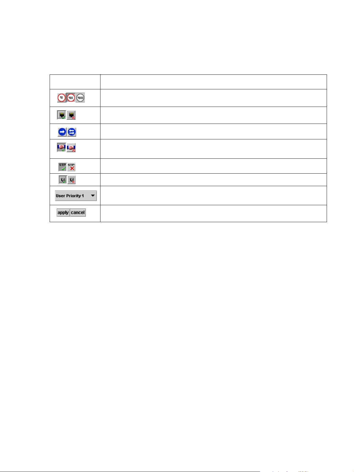
The table below displays the buttons on the Get/Set Toolbar and explains their functions and
settings.
Table 4: Get/Set Toolbar
Button Description
Get and set the port’s speed: 10 Mbps, 100 Mbps, 1000 Mbps.
Get and set the port’s status: Enabled, Disabled.
Get and set the port’s mode: Half duplex, Full duplex.
Get and set the port’s auto-negotiation status:
Auto-negotiation Enabled, Auto-negotiation Disabled.
Get and set the port’s STP mode: Enabled, Disabled.
Get and set the port’s Power over Ethernet (not relevant for G450).
Get and set the port’s priority. Select a priority level between 1 and 8 using
the pull-down listbox.
Apply or cancel the configuration changes made with the Get/Set Toolbar.
Note: The Apply/Cancel buttons only appear when changes are made to the
configuration.
You can toggle the display of the Get/Set toolbar. To toggle the display of the Get/Set toolbar,
select View > Toolbars > Show Get/Set Toolbar.
26 Avaya Integrated Management Release 4.0.1 Software Update Manager
Page 27

Tree View
The Tree View shows a hierarchical representation of the structure of the Avaya G250/G350/
G450 Device. To select ports, modules or media modules, click their icons in the Tree View.
When an element is selected in the Tree View, the corresponding element is selected in the
Chassis View.
The highest level of the Tre e View represents the device. The second level shows modules. The
third level shows ports. This includes ports on expansion modules.
To expand the view of a contracted element in the tree or to contract the view of an expanded
element in the tree:
Double-click the element.
Or
Click the handle next to the element you want to expand or contract.
The G250/G350/G450 Device Manager User Interface
Desktop
The central section of the application window is the Desktop. This area can be resized by
dragging the vertical splitter bars with the mouse. Floating dialog boxes and tables can be
resized. The Chassis View and floating dialog boxes and tables can also be minimized.
Minimized windows appear at the bottom of the Desktop.
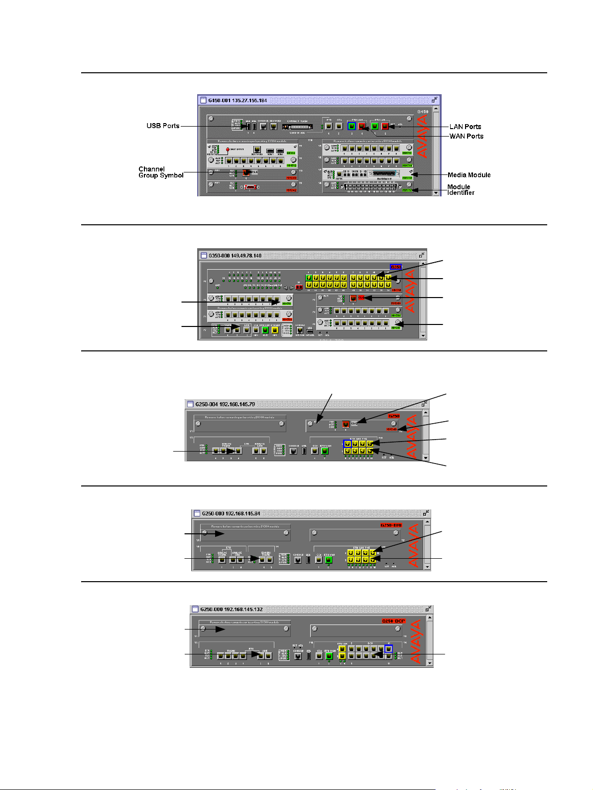
Chassis View
The Chassis View is a graphical representation of the Avaya G250/G350/G450 device. The
Avaya G250/G350/G450 device can contain several Avaya G250/G350/G450 modules. The
Chassis View shows all of the devices’ modules and ports. The colors of the modules and port s
in the Chassis View reflect their status.
When you hold the cursor over a port’s icon in the Chassis View, a label appears with the port
number, its VLAN ID, and the last fault that occurred on the port.
Issue 5 October 2007 27
Page 28
Device Manager
Modul e
Identifier
Fixed Ports
Power
Symbols
Port
Symbols
Channel
Group Symbol
Media
Module
Media
Module
Module
Identifier
Fixed
Ports
Channel
Group
Symbol
Power
Symbols
Port
Symbols
Module
Expansion
Slot
Power
Symbols
Port
Symbols
Fixed
Ports
Module
Expansion
Slot
Port
Symbols
Fixed
Ports
Figure 3: Avaya G450 Chassis View
Figure 4: Avaya G350 Chassis View
Figure 5: Avaya G250 Chassis View
Figure 6: Avaya G250 - BRI Chassis View
Figure 7: Avaya G250 - DCP Chassis View
28 Avaya Integrated Management Release 4.0.1 Software Update Manager
Page 29

The G250/G350/G450 Device Manager User Interface
Media
Module
Fixed
Ports
Power
Symbols
Port
Symbols
Module
Identifier
Figure 8: Avaya G250 - DS1 Chassis View
When viewing selected dialog boxes, the color of the port indicates the status of the port with
regard to the application. The port selected to be the base port appears dark blue. The ports
selected to be additional ports appear cyan.
The following table provides a list of the possible port colors in the Chassis Vi ew and their
meaning.
Table 5: Chassis View Port Colors
Color Meaning
Green The port is enabled, and its status is Okay.
Yellow The port is enabled, and its status is Warning.
Red The port is enabled, and its status is Fatal.
Light Gray The port is disabled.
Dark Gray The port is not associated with the assignment.
White The port is logically available for assignment.
Dark Blue The port has been assigned the primary position in an application.
Cyan The port has been assigned a secondary position in an application.
Issue 5 October 2007 29
Page 30
Device Manager
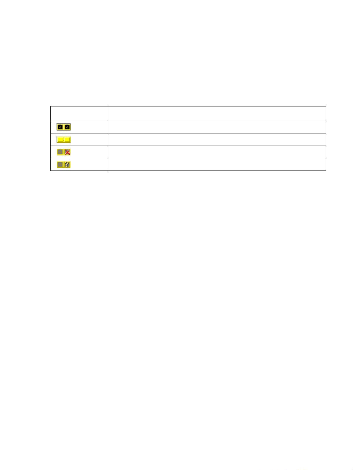
GBIC Ports
The Avaya MM314 media modules contain a GBIC (GigaBit Interface Converter) port that
houses removable transceiver modules. The Chassis View reflects the management status of
this ports. The following table shows the possible appearances of this port in the Chassis View
and provides the corresponding management status of the port.
Table 6: GBIC Port Status
GBIC Port Status
GBIC ports that contain the following types of transceiver modules can be configured:
● Supported transceiver modules
The GBIC port contains a supported transceiver module.
There is no transceiver module present in the GBIC port.
The transceiver module in the GBIC port is not supported.
The transceiver module in the GBIC port is of an unknown type.
● No transceiver modules
● Unknown transceiver modules
GBIC ports that contain unsupported transceiver modules cannot be configured.
Selecting Elements
You can select modules and ports.
To select a module:
In the Chassis View, click the module’s label.
Or
In the Tree View, click the module’s icon. The module’s label is highlighted in the Chassis
View and the Tree View.
To select a port:
In the Chassis View, click the port.
Or
In the Tree View, click the port’s icon. The port is highlighted in the Chassis View and the
Tree View.
To select multiple elements, press CTRL while clicking on each element to be selected.
30 Avaya Integrated Management Release 4.0.1 Software Update Manager
Page 31

Dialog Area
Note:
The area to the right of the Chassis View is where all dialog boxes, tables, and wizards first
appear. This area can be resized by dragging the vertical splitter bar with the mouse. When a
dialog box, table, or wizard opens, it replaces the current dialog box open in the Dialog Area. To
view more than one dialog box or table simultaneously, click the pushpin in the upper
right-hand corner of the dialog box. The dialog box becomes a floating dialog box and moves to
the Desktop.
To restore a dialog box to the Dialog Area, click the toolbar button or icon that opened the dialog
box. The dialog box returns to the Dialog Area.
Avaya G250/G350/G450 Modes
The Avaya G250/G350/G450 Device Manager has two modes:
Avaya G250/G350/G450 Modes
● Configuration mode
● Port RMON mode
Note: When the Avaya G250/G350/G450 Manager is installed as a standalone
manager and when running the Avaya G350/G450 Manager via Web
Management, Port SMON is not available.
When in configuration mode, you can view and change the configuration of the Avaya G250/
G350/G450 Device and individual ports. When in Port RMON mode, you can view graphical
representations of the traffic on individual ports.
Issue 5 October 2007 31
Page 32

Device Manager
To switch to configuration mode:
Click .
Or
Select View > Configuration.
To switch to Port RMON mode:
Click .
Or
Select View > Port RMON.
Refreshing Device Information
You can refresh the information in the Avaya G250/G350/G450 Device Manager. To refresh
Avaya G250/G350/G450 Device information, select View > Refresh. The Avaya G250/G350/
G450 Device Manager refreshes its device information and updates the display.
Using Dialog Boxes and Tables
Dialog boxes and tables in the Avaya G250/G350/G450 Manager application have a common
set of buttons. The following table displays the buttons and explains their functions:
Table 7: Dialog Box Buttons
Button Function
Refreshes the information in the table or dialog box. This clears any changes
made to the table or dialog box and not yet sent to the device.
Sends the information from the table or dialog box to update the device.
Adds a row to the table.
Deletes the selected rows of the table.
Undoes all changes to the selected row in a table.
32 Avaya Integrated Management Release 4.0.1 Software Update Manager
Page 33

Using Avaya G250/G350/G450 Device Manager Help
Note:
Using Avaya G250/G350/G450 Device Manager Help
This section explains how to use the on-line help in the Avaya
G250/G350/G450 Device Manager. The on-line help can be opened to the contents page or
directly to a topic of interest.
Note: When running the Avaya G350/G450 Manager via Web Management, on-line
help is only available if you have installed the on-line help on your network and
configured the device with the location of the help files.
Opening the Help to the Contents Page
To open the help to the contents page, select Help > Contents. The on-line help opens to the
contents page.
Opening the Help to a Topic of Interest
To open the help directly to a topic of interest:
1. Click .
Or
Select Help > Help On. The cursor changes to the sha pe of an arrow with a question mark.
2. Click on a point of interest in the Avaya G250/G350/G450 Device Manager. The on-line
help opens to a topic explaining the feature that was clicked.
Issue 5 October 2007 33
Page 34

Device Manager
34 Avaya Integrated Management Release 4.0.1 Software Update Manager
Page 35

Chapter 3: Device Configuration
This chapter explains how to view and set the various configuration parameters relevant to the
Avaya G250/G350/G450 Device. It includes the following sections:
● Viewing Device Configuration - View high-level information about the Avaya G250/G350/
G450 Device.
● Viewing Module Configuration - View information specific to an Avaya G250/G350/G450
module in the device.
● Viewing Port Configuration - View information specific to the ports on the Avaya G250/
G350/G450 Device.
● Configuring the External Modem - View information specific to an external modem
connected to the Avaya G250/G350/G450 Device.
● Configuring the Dialer - View information specific to an external dial-up modem connected
to the Avaya G250/G350/G450 Device.
● Resetting the Device - Reset the Avaya G250/G350/G450 Device.
To view configuration information, you must be in Configuration mode. To switch to Configuration
mode:
Click .
Or
Select View > Configuration.
Viewing Device Configuration
The Device Configuration dialog box provides you with high-level configuration information
specific to the Avaya G250/G350/G450 Device. This information is divided into the following:
● Device Configuration - General Tab - Provides detailed information about the device such
as the device’s name, addresses, contact person, location, type, description, the number
of modules in the device, and the management VLAN ID.
● Media Gateway Configuration Tab - Provides detailed information on the configuration
settings of the Media Gateway function of the device. For more information on Media
Gateway Configuration, refer to “Media Gateway Functions” on page 71
● Media Gateway Controller Configuration Tab - Provides detailed Quality of Service
statistics for the Media Gateway function of the device. For more information, refer to
“Media Gateway Functions” on page 71
● Voice over IP Resources Tab - Provides administration parameters for the VoIP engine.
For more information on V oIP Resources, refer to “VoIP Engine Configuration” on page 77
● Voice over IP Status Tab - Provides detailed operating statistics for the VoIP engine. For
more information, refer to “VoIP Engine Configuration” on page 77
.
.
.
.
Issue 5 October 2007 35
Page 36

Device Configuration
Device Configuration - General Tab
To view the General tab of the Device Configuration dialog box:
Select Configure > Device Information. The Device Configuration d ialog box opens to the
General tab.
Figure 9: Device Configuration Dialog Box - General Tab
36 Avaya Integrated Management Release 4.0.1 Software Update Manager
Page 37

Viewing Device Configuration
The following table provides a list of the fields in the General tab of the Device Configuration
dialog box and their descriptions.
Table 8: Device Configuration Fields - General Tab
Field Description
System Name Logical name of the device, as defined on the SNMP agent of the
device.
MG Identifier Identification number of the Media Gateway.
FW version Firmware release the device is running.
Contact The individual responsible for the maintenance of this device.
Physical Location The current physical location of this device.
System Description A description of the device.
Number Of Modules The number of Media Modules and expansion modules in the
chassis.
Chassis Serial
Number
Chassis
Configuration
The serial number of the chassis (read only) (relevant only for the
Avaya G450 Device).
The configuration symbol of the chassis (read only) (relevant only for
the Avaya G450 Device).
Symbol
VLAN MAC Address The MAC address of the VLAN interface.
WAN1 MAC Address The MAC address of the WAN1 port (relevant only for the
Avaya G450 Device).
WAN2 MAC Address The MAC address of the WAN2 port (relevant only for the
Avaya G450 Device).
SERVICES MAC
Address
The MAC address of the Services port (relevant only for the
Avaya G450 Device).
Current DS Mode Speed of serial link. Possible values are:
● T1
● E1
Next DS Mode Speed of backup serial link, if configured. Possible values are:
● T1
● E1
Current PMI
Interface currently designated as Primary Management Interface.
Interface
1 of 2
Issue 5 October 2007 37
Page 38

Device Configuration
Table 8: Device Configuration Fields - General Tab (continued)
Field Description
Current PMI IP
IP address of Primary Management Interface.
Address
Current PMI Subnet
Subnet mask of Primary Management Interface.
Mask
Next PMI Interface Interface configured by the gateway to be the new Primary
Management Interface. If you set this parameter using the CLI, the
new setting only takes effect after the next device reset.
Next PMI IP Address IP address configured by the gateway to be the new Primary
Management Interface. If you set this parameter using the CLI, the
new setting only takes effect after the next device reset.
Default Gateway IP address of the default network gateway device.
ICC VLAN VLAN of which the device is a member.
Operational Status The operational status of the device. Possible values are:
● OK - Device is operational.
● Down - Device is reporting faults making it unable to function.
● Fatal - Device is reporting faults that are unrecoverable.
Fault Messages Number of fault messages reported by the device.
2 of 2
For more information on the user interface, refer to “Using Dialog Boxes and Tables” on
page 32.
38 Avaya Integrated Management Release 4.0.1 Software Update Manager
Page 39

Device Configuration - Advanced Tab
Note:
The Device Configuration Dialog Box - Advanced Tab provides you with network bridging
information about the Avaya G250/G350/G450 Device.
Note: Avaya G250 Devices do not support the spanning tree protocol, therefore the
STP fields do not appear for an Avaya G250 Device.
Figure 10: Device Configuration Dialog Box - Advanced Tab
Viewing Device Configuration
The following table provides a list of the fields in the Advanced tab of the Device Configuration
dialog box and their descriptions.
Table 9: Device Configuration Fields - Advanced Tab
Field Description
STP Mode Spanning Tree status of the device.
STP Priority Priority value used in Spanning Tree calculations.
1 of 2
Issue 5 October 2007 39
Page 40

Device Configuration
Table 9: Device Configuration Fields - Advanced Tab (continued)
Field Description
STP Version Version of Spanning Tree on the device. Possible values are:
STP Max Age The maximum amount of time before the Spanning Tree table
STP Hello Time The amount of time between sending Spanning Tree updates if
STP Forward Delay The amount of time for the device to begin forwarding packet s when
STP Bridge Max Age The maximum amount of time before Spanning recalculates if there
● STP Compatible - Standard Spanning-Tree Protocol
● RSTP - Rapid Spanning-Tree Protocol
recalculates if there is no change in the device status, measured in
milliseconds.
there are no detected changes in the device’s network connections,
measured in milliseconds.
first joining a network, measured in milliseconds.
is no change in network bridging status, measured in milliseconds.
STP Bridge Hello
Time
The amount of time between sending Spanning Tree updates if
there are no detected changes in the overall bridged network
topology, measured in milliseconds.
STP Bridge Forward
Delay
The amount of time for the device to begin forwarding packets after
recalculating its Spanning Tree table based on a change in network
topology, measured in milliseconds.
Aging Time (sec) The amount of time MAC addresses remain in the CAM table.
LLDP Mode The status of Link Layer Discovery Protocol (LLDP) Mode on the
device:
● Enable - Use LLDP Mode.
● Disable - Do not use LLDP Mode.
LLDP Tx Interval The amount of time between packet transmissions on the device.
LLDP Tx Hold
Multiplier
The LLDP time-to-live value expressed as a multiple of the value
configured in the LLDP Tx Interval field.
LLDP Tx Delay The delay between successive LLDP frame transmissions initiated
by status changes in LLDP.
LLDP Re-Init Delay The amount of time the device is instructed to wait before
re-initiating LLDP.
2 of 2
For more information on the user interface, refer to “Using Dialog Boxes and Tables” on
page 32.
40 Avaya Integrated Management Release 4.0.1 Software Update Manager
Page 41

Device Configuration - FRU Tab
The Device Configuration Dialog Box - FRU Tab provides you with information about the Field
Replaceable Units (FRU) of the Avaya G450 Device.
Figure 11: Device Configuration Dialog Box - FRU Tab
Viewing Device Configuration
The following table provides a list of the fields in the FRU tab of the Device Configuration dialog
box and their descriptions.
Table 10: Device Configuration Fields - FRU Tab
Field Description
Mainboard Serial Number The serial number of the mainboard.
Mainboard Configuration
Symbol
The configuration symbol of the mainboard.
1 of 3
Issue 5 October 2007 41
Page 42

Device Configuration
Table 10: Device Configuration Fields - FRU Tab (continued)
Field Description
PSU #1 Operational Status The operational status of Power Supply 1. Possible values are:
PSU #1 Fault Message The fault message reported by Power Supply 1. Possible
PSU #2 Operational Status The operational status of Power Supply 2. Possible values are:
● OK - The power supply is operational.
● Fault - The power supply is reporting faults making it
unable to function.
● Not Present - The power supply is not installed.
● Unknown - The power supply is reporting an unknown
fault.
values are:
● No Fault
● Malfunction
● AC Fault
● Malfunction & AC Fault
● Single Fan Fault
● Multiple Fan Fault
● OK - The power supply is operational.
● Fault - The power supply is reporting faults making it
unable to function.
● Not Present - The power supply is not installed.
● Unknown - The power supply is reporting an unknown
fault.
PSU #2 Fault Message The fault message reported by Power Supply 2. Possible
values are:
● No Fault
● Malfunction
● AC Fault
● Malfunction & AC Fault
● Single Fan Fault
● Multiple Fan Fault
Fan Tray Operational
Status
The operational status of the fan tray. Possible values are:
● OK - The fan tray is operational.
● Fault - The fan tray is reporting faults making it unable
to function.
● Not Present - The fan tray is not installed.
● Unknown - The fan tray is reporting an unknown fault.
2 of 3
42 Avaya Integrated Management Release 4.0.1 Software Update Manager
Page 43

Viewing Device Configuration
Table 10: Device Configuration Fields - FRU Tab (continued)
Field Description
Fan Tray Fault Message The fault message reported by the fan tray. Possible values
are:
● None
● Malfunction
● AC Fault
● Malfunction & AC Fault
● Single Fan Fault
● Multiple Fan Fault
Memory #1 Displays a description of the memory installed in slot 1.
Memory #2 Displays a description of the memory installed in slot 2.
Media Resource #1 Displays a description of the media resource installed in slot 1.
Media Resource #2 Displays a description of the media resource installed in slot 2.
Media Resource #3 Displays a description of the media resource installed in slot 3.
Media Resource #4 Displays a description of the media resource installed in slot 4.
3 of 3
Issue 5 October 2007 43
Page 44
Device Configuration
Note:
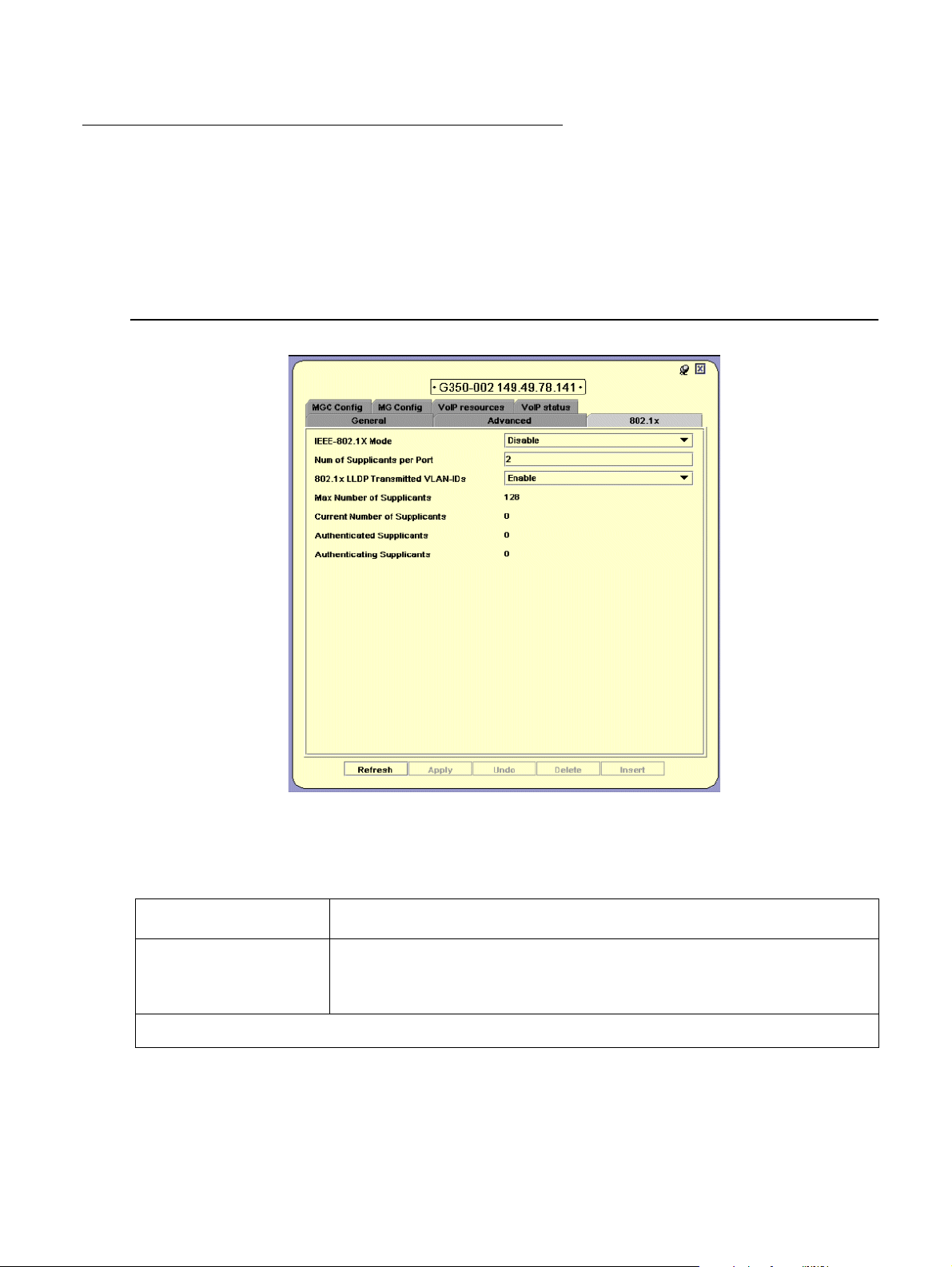
Device Configuration - 802.1x Tab
The Device Configuration Dialog Box - 802.1x tab provides you with support for the general
configuration of the 802.1x application.
Note: Avaya G450 Devices do not support the 802.1x protocol, therefore the 802.1x tab
does not appear for an Avaya G450 Device.
Figure 12: Device Configuration Dialog Box - 802.1x Tab
The following table provides a list of the fields in the 802.1x tab of the Device Configuration
dialog box and their descriptions.
Table 11: Device Configuration Fields - 802.1x Tab
Field Description
IEEE-802.1x Mode 802.1x application status of the device. Possible values are:
● Enable
● Disable
44 Avaya Integrated Management Release 4.0.1 Software Update Manager
1 of 2
Page 45

Note:
Table 11: Device Configuration Fields - 802.1x Tab (continued)
Field Description
Viewing Module Configuration
Num of Supplicants
per Port
802.1x LLDP
Transmitted
VLAN-IDs
Max Number of
Supplicants
Current Number of
Supplicants
Authenticated
Supplicants
Authenticating
Supplicants
Number of supplicants per port allowed in
MAC-Based-Authentication. This parameter is not relevant in
port-based-authentication mode.
Possible values are 1-8. The default value is 2.
When enabled, allows transmission of port LLDP information (PVID,
Port Vlan) in the LLDP packet sent to the A vaya IP phone connected
to the port.
The device/system maximum number of supplicants.
The current number of supplicants connected to the device/system.
The number of authenticated supplicants connected to the device/
system.
Number of supplicants connected to the device/system being
authenticated (not authenticated yet).
2 of 2
Viewing Module Configuration
The Module Configuration dialog box provides you with information specific to a selected
module.
● Module Configuration - General Tab - Provides detailed information about the module,
such as the module’s position in the device, the module’s type, description, number of
ports, mode of operation, and any faults occurring on the module.
● Module Configuration - Power Tab - Provides information about the module’s Power over
Ethernet (PoE) configuration. For more information, refer to “Power over Ethernet” on
page 67.
Note: The information fields in the Module Configuration dialog box vary according to
the type of module selected.
Issue 5 October 2007 45
Page 46

Device Configuration
Note:
Module Configuration - General Tab
To view the General tab of the Module Configuration dialog box for a selected module:
Click the module symbol in the Tree View.
Or
Click the module’s label in the Chassis View. The Module Configuration dialog box opens to
the General tab.
Figure 13: Module Configuration Dialog Box - General Tab
Note: Module Configuration fields may vary somewhat based on the Media Module.
46 Avaya Integrated Management Release 4.0.1 Software Update Manager
Page 47

Viewing Module Configuration
Module Description G250 G350 G450
MM710 1 x voice T1/E1 port Y Y
MM711 8 x universal analog Y Y
MM712 8 x DCP 2 wire ports Y Y
MM714 Analog 4 line + 4 trunk Y Y
MM720 8 x ISDN BRI Y Y
MM722 2 x ISDN BRI Y Y
MM717 24 x DCP 2 wire ports Y Y
MM716 24 analog stations Y Y
MM340 1 x T1/E1 data Y Y Y
MM342 1 x USP (V.35/X.21) Y Y Y
S8300B Locally hosted CM server in ICC or LSP mode Y Y Y
S8300C Locally hosted CM server in ICC or LSP mode Y Y Y
Mm312 24 DCP phone ports Y
MM314 24 PoE Ethernet Y
MM316 48 PoE Ethernet expansion module Y
The following table provides a list of the fields in the Module Configuration dialog box and their
descriptions.
Table 12: Module Configuration Dialog Box
Field Description
MM Type Model of Media Module.
Support for the different devices is described below:
MM Description Description of Media Module.
Serial # Unique identifier for individual Media Module.
HW Version Release version of Media Module hardware.
FW Version Release version of Media Module firmware.
Number of Ports The number of ports in the Media Module.
1 of 2
Issue 5 October 2007 47
Page 48

Device Configuration
Table 12: Module Configuration Dialog Box (continued)
Field Description
Operational
Status
The operational status of the Media Module. Possible values are:
● OK - Media Module is operational.
● Down - Media Module is reporting faults making it unable to
function.
● Fatal - Media Module is reporting faults that are unrecoverable.
Fault Messages Number of fault messages reported by the Media Module.
Viewing Port Configuration
The Port Configuration dialog box contains tabs that provide you with information specific to a
selected port.
● Port Configuration - General Tab - Provides detailed information about the port, such as
the port name, type, functionality, status, VLAN ID, mode of operation, and any faults
occurring on the port.
● Port Configuration - Advanced Tab - Provides detailed information about the port’s STP
configuration and port classification.
2 of 2
● Port Configuration - Power Tab - Provides information about the port’s PoE configuration.
For more information about PoE, refer to “Power over Ethernet” on page 67
● Port Configuration - 802.1X Tab - Provides detailed information about the port’s 802.1x
.
security configuration.
● Port Configuration - LLDP Tab - Provides detailed information about the port’s LLDP
configuration.
● Get/Set Toolbar - Provides an alternative, quick method to view and change the port’s
configuration. For more information on the Get/Set Toolbar, refer to “Get/Set Toolbar” on
page 25.
48 Avaya Integrated Management Release 4.0.1 Software Update Manager
Page 49

Port Configuration - General Tab
Note:
To view the General tab of the Port Configuration dialog box for a selected port:
Click the port symbol in the Chassis View.
Or
Click the port’s icon in the Tree View. The Port Configuration dialog box opens to the
General tab.
Figure 14: Port Configuration Dialog Box - General Tab
Viewing Port Configuration
The following table provides a list of the fields in the Port Configuration Dialog Box - General tab
and their descriptions.
Note: Some fields will vary based on the Media Module on which the port resides.
Table 13: Port Configuration Dialog Box - General Tab
Field Description
Port Name The user can define a logical name to the port for ease of use.
1 of 3
Issue 5 October 2007 49
Page 50

Device Configuration
Table 13: Port Configuration Dialog Box - General Tab (continued)
Field Description
Port Type The port type; optionally includes reference to the module to which it
Port Functionality The physical media type of the selected port. If the port conforms to
is attached and port connector type.
a certain standard (Repeater, Transceiver, 10BaseT, etc.), this
standard is displayed. If the port does not conform to any standard,
Private is displayed.
Administrative
Status
The administrative state of the selected port:
● Enabled - the port is enabled and can transmit and receive
packets.
● Disabled - the port is disabled and cannot transmit or receive
packets.
Tagging Mode The port’s operational mode regarding VLANs. The possible modes
are:
● Transmits each outgoing packet in untagged format if it
belongs to the port’s VLAN. Otherwise, it discards the packet.
● VLAN tagging, per IEEE 802.1Q VLAN standard. The port will
transmit frames with a VLAN ID of 1 - 3071 for Avaya G250/
G350 Devices and 1 - 4090 for Avaya G450 Devices.
VLAN ID The VLAN number of the port.
Port Priority Level The priority level of packets exiting the port or ports on the module.
For effective transmission, multimedia packets must be received at
regular intervals. To ensure this, you can assign priorities to packets
coming out of a port.
Whenever traffic load is extreme and a port cannot accept all
incoming packets, packets sent from a port with the highest priority
will pass through first. However, a fairness mechanism will allow low
priority packets to eventually enter the bus.
Possible values are: User Priority 0...User Priority 7
Auto Negotiation
Mode
The configured state of the Auto-Negotiation protocol between two
stations. When enabled, Auto-Negotiation detects the highest
common denominator for communication between endstations, and
sets both to the same highest common setting. It also delivers
remote link status.
For 10BaseT and 100BaseT ports, Auto-Negotiation determines the
speed and Duplex Mode of communication between the endstations.
For Gigabit ports, Auto-Negotiation determines the Flow Control
setting of the ports.
For more information, refer to Auto-Negotiation in The Reference
Guide.
50 Avaya Integrated Management Release 4.0.1 Software Update Manager
2 of 3
Page 51

Table 13: Port Configuration Dialog Box - General Tab (continued)
Field Description
Viewing Port Configuration
Auto Negotiation
Status
The operational state of the Auto-Negotiation protocol between two
stations. Possible statuses are:
● Pass - the Auto-Negotiation protocol is enabled and a
common protocol has been established.
● In Progress - the Auto-Negotiation protocol is in the process
of detecting the communication capabilities of the endstations
and setting them to the highest common denominator.
● Fail - the Auto-Negotiation protocol was not able to detect the
communication capabilities of the end station, or was unable
to set them to the highest common denominator.
● Disabled - The Auto-Negotiation protocol is disabled.
Duplex Mode The state of communication of the selected port. Possible values
are:
● Full Duplex - the port can send and receive simultaneously.
● Half Duplex - the port can either receive or send, but cannot
do both simultaneously.
Speed Mode The rate of communication of the selected port. Possible values are:
● Ethernet
● Fast Ethernet
● Gigabit Ethernet
Flow Control Mode The state of flow control on the selected port.
Operational Status The warning level of the selected port. Possible values are:
● OK
● Warning
● Fatal
Fault Messages A list of fault messages.
For more information on the user interface, refer to “Using Dialog Boxes and Tables” on
page 32.
Issue 5 October 2007 51
3 of 3
Page 52

Device Configuration
Note:
Port Configuration - Advanced Tab
To view the Advanced tab of the Port Configuration dialog box for a selected port:
1. Click the port symbol in the Chassis View.
Or
Click the port’s icon in the Tree View. The Port Configuration dialog box opens to the
General tab.
2. Click the Advanced tab. The Port Configuration Dialog Box - Advanced Tab opens.
Note: Avaya G250 Devices do not support the spanning tree protocol, therefore the
STP fields do not appear for Avaya G250 Device ports.
Figure 15: Port Configuration Dialog Box - Advanced Tab
52 Avaya Integrated Management Release 4.0.1 Software Update Manager
Page 53

Viewing Port Configuration
The following table provides a list of the fields in the Port Configuration Dialog Box - Advanced
Tab and their descriptions.
Table 14: Port Configuration Dialog Box - Advanced Tab
Field Description
Port STP Mode Configured status of Spanning Tree. Possible values are:
● Enable
● Disable
Port STP St ate Spanning Tree state on the port. Possible values are:
● Blocking - Port is blocking attempts to join Spanning Tree.
● Listening - Port is discovering other devices in the Spanning
Tree.
● Learning - Port is calculating Spanning Tree values prior to
joining the Spanning Tree.
● Forwarding - Port is forwarding traffic within the Spanning
Tree.
STP Admin Edge The administrative state of the edge port parameter. Possible states
include:
● TRUE - This port is assumed to be an edge port.
● FALSE - This port is assumed not to be an edge-port.
STP Oper Edge The operational state of the edge port parameter.
● TRUE - This port is operating in the state specified in STP
Admin Edge.
● FALSE - A BPDU was received by the port.
STP Admin P2P The administrative point-to-point st atus of the LAN segment attached
to this port. Possible statuses include:
● True - The port should always be treated as if it is connected to
a point-to-point link.
● forceFalse - The port should be treated as having a shared
media connection.
● Auto - The port is considered to have a point-to-point link if it is
an Aggregator and all of its members are aggregative, or if the
MAC entity is configured for full duplex operation, either
through auto-negotiation or by management means.
STP Oper P2P The operational point-to-point status of the LAN segment att ach ed to
this port. It indicates whether or not a port is considered to have a
point-to-point connection.
The value is determined by STP Admin P2P.
1 of 2
Issue 5 October 2007 53
Page 54

Device Configuration
Table 14: Port Configuration Dialog Box - Advanced Tab (continued)
Field Description
STP Admin Path
Cost
The administratively assigned value for the contribution of this port to
the path cost of paths towards the spanning tree root. A value of 0
assigns the automatically calculated default Path Cost value to the
port.
STP Admin Path Cost complements STP Path Cost, which returns
the operational value of the path cost.
STP Path Cost The operational cost factor used by Spanning Tree Algorithm to
determine the most efficient route for forwarding traffic to its
destination while removing loops in the network.For more
information, refer to Spanning T ree Algorithm (STA) in The Reference
Guide.
STP Priority The priority factor used by STP to determine the activity status of an
individual port on the Spanning Tree.
STP Force Migration When checked and in RSTP mode, the port is forced to transmit
RSTP BPDUs.
Port Classification The classification of a specific port. Port Classification allows network
managers to specify each port level’s importance. The possible
states are:
● Regular - Normal Users
● Valuable - Servers or critical users.
For more information refer to Port Classification in The Reference
Guide.
For more information on the user interface, refer to “Using Dialog Boxes and Tables” on
page 32.
Port Configuration - 802.1X Tab
802.1x port security requires a user connected to a port on the network to be authenticated by
an authentication server.
When a user connects to a port configured with 802.1x port security, the port forwards an
authentication packet to a Radius authentication server. The authentication server checks if the
user is authorized to use the port, and either allows or blocks the user’s access to the port.
The port can be configured to automatically reauthenticate the user . If the reauthentication fails,
the user is denied further access to the port. For more information, refer to “Port Configurat ion -
General Tab” on page 49.
2 of 2
54 Avaya Integrated Management Release 4.0.1 Software Update Manager
Page 55

Viewing Port Configuration
Note:
The 802.1x application supports two modes of operation:
● Port-based-authentication, which is backwards compatible to the previous 802.1x
application behavior, and is used for a single-supplicant case.
● MAC-based-authentication for cases where multiple supplicants are connected per port.
For more information, refer to “Device Configuration - 802.1x Tab” on page 44
.
The 802.1X tab of the Port Configuration dialog box provides you with detailed 802.1X
authentication information about the selected port.
Note: Avaya G450 Devices do not support the 802.1x protocol, therefore the 802.1x t ab
does not appear for an Avaya G450 Device.
Figure 16: Port Configuration Dialog Box - 802.1X Tab
Issue 5 October 2007 55
Page 56

Device Configuration
The following table provides a list of the fields in the 802.1X table of the Port Configuration
dialog box and their descriptions:
Table 15: Port Configuration Dialog Box - 802.1X Tab Parameters
Field Description
EAP State Entry Access Protocol authentication status. Possible values are:
Backend Auth State The current status of the Backend Authentication state machine.
● Initialize
● Disconnected
● Connecting
● Authenticating
● Authenticated
● Aborting
● Held
● Force Auth
● Force Unauth
Possible values are:
● Request
● Response
● Success
● Fail
● Timeout
● Idle
● Initialize
Controlled Port
Status
Controlled Port
Control
IEEE-802.1X Port
Mode
The current value of the Controlled Port status. Possible values are:
● Authorized
● Unauthorized
The current status of the Controlled Port control. Possible values
are:
● Force Authorized
● Force Unauthorized
The 802.1x mode of operation. Possible values are:
● Port Based Authentication - used for a single-supplicant case.
This mode is backwards compatible to the previous 802.1x
application behavior.
● MAC Based Authentication - for cases where multiple
supplicants are connected per port. For more information,
refer to “Device Configuration - 802.1x Tab” on page 44
.
Initialize Forces initialization of the port. Checking the Initialize checkbox and
clicking Apply forces the port to be initialized immediately. This
checkbox is only active when IEEE-802.1x mode is enabled.
1 of 2
56 Avaya Integrated Management Release 4.0.1 Software Update Manager
Page 57

Viewing Port Configuration
Table 15: Port Configuration Dialog Box - 802.1X Tab Parameters (continued)
Field Description
Reauthenticate Forces reauthentication of the port. Checking the Reauthenticate
checkbox and clicking Apply forces the port to be reauthenticated
immediately. This checkbox is only active when IEEE-802.1x mode
is enabled.
Quiet Period (sec) The amount of time, in seconds, between sending authentication
requests.
Tx Period (sec) The amount of time, in seconds, in which an authentication request
must be answered.
Supp Timeout (sec) The amount of time, in seconds, after which an authentication
request is suppressed.
Server Timeout (sec) The amount of time, in seconds, before timing out an authentication
request.
Max Request The maximum number of times a request for authentication is sent
before timing out.
ReAuthPeriod (sec) The amount of time, in seconds, after which the port connection
should be reauthenticated.
ReAuth Enabled The state of reauthentication on the port. Possible values are:
● True - The port connection is reauthenticated after the reAuth
Period.
● False - The port connection is not reauthenticated. The
reAuth Period is ignored.
Current Number of
The current number of supplicants on this port.
Supplicants
Authenticated
The number of authenticated supplicants on this port.
Supplicants
Authenticating
Supplicants
The number of supplicants connected to the port being
authenticated (not authenticated yet).
For more information on the user interface, refer to “Using Dialog Boxes and Tables” on
page 32.
2 of 2
Issue 5 October 2007 57
Page 58

Device Configuration
Note:
Port Configuration - LLDP Tab
Link Layer Discovery Protocol (LLDP) is a neighbor discovery protocol, which allows Ethernet
network devices to search for , and request informatio n from, other LLDP enabled de vices on the
network. LLDP defines a standard method for Ethernet network devices, such as switches,
routers, and wireless LAN access points, to advertise information about themselves to other
nodes on the network.
LLDP also allows Ethernet network devices to search for, and request information from, other
devices using the LLDP protocol.
The following details can be advertised using LLDP on the Avaya G250/G350/G450 Device:
● System Name
● Chassis ID
● Port ID
● System Description
● System Capabilities
● Port Description
● Management Address
Note: Chassis ID and Port ID are always advertised when LLDP is enabled.
To view the LLDP tab of the Port Configuration dialog box for a selected port:
1. Click the port symbol in the Chassis View.
Or
Click the port’s icon in the Tree View. The Port Configuration dialog box opens to the
General tab.
2. Click LLDP. The Port Configuration dialog box - LLDP Tab opens.
58 Avaya Integrated Management Release 4.0.1 Software Update Manager
Page 59

Figure 17: Port Configuration Dialog Box - LLDP Tab
Viewing Port Configuration
The following table provides a list of the fields in the LLDP tab of the Port Configuration dialog
box and their descriptions:
Table 16: Port Configuration Dialog Box - LLDP Tab Parameters
Field Description
LLDP Admin Status The status of LLDP mode on the device. Possible values are:
● Tx Only - LLDP mode is enabled, and is configured to only
accept Tx traffic.
● Rx Only - LLDP mode is enabled, and is configured to only
accept Rx traffic.
● Tx and Rx - LLDP mode is enabled and is configured to
accept both Tx and Rx traffic.
● Disabled - LLDP mode is disabled.
LLDP TLVs Transmission
System Name The system’s network name. When checked, the system advertises
its name to the network.
System Description A brief description of the system (i.e., G250/G350/G450). When
checked, this TLV is advertised.
System Capabilities A brief description of the system’s capabilities. When checked, this
TLV is advertised.
Port Description A brief description of the device port. When checked, this TLV is
advertised.
1 of 2
Issue 5 October 2007 59
Page 60

Device Configuration
Note:
Table 16: Port Configuration Dialog Box - LLDP Tab Parameters (continued)
Field Description
Management Addr The device’s management address. When checked, this TLV is
LLDP TLVs Reception
Chassis Id The received Chassis ID TLV.
Port Id The received Port ID TLV of the device port.
Port Description The received Port Description TLV of the device port.
System Name The received System Name TLV associated with the Chassis ID.
System Description The received System Description TLV associated with the Chassis
System Capabilities The received System Capabilities TLV associated with the Chassis
advertised.
ID.
ID.
Management
Address
The received IP Management Address TLV associated with the
Chassis ID.
Configuring the External Modem
You can configure and view information specific to an external modem connected via the
Console or USB ports using the L2 Device Manager dialog box. These ports are context
sensitive, and the Modem tab for each port is distinct.
Note: To configure a dial-up modem, refer to “Configuring the Dialer” on page 46.
2 of 2
60 Avaya Integrated Management Release 4.0.1 Software Update Manager
Page 61

Configuring the External Modem
To view the L2 Device Manager for the Console port:
In the Chassis View, click the Console icon.
Or
In the Tree View, click the Console icon. The L2 Device Manager for the Console port
opens.
Figure 18: L2 Device Manager - Console Port
The following table provides a list of the fields in the L2 Device Manager for the Console port.
Table 17: L2 Device Manager - Console Port
Field Description
Asynch Mode The interface admin status of the console port. Possible values
include:
● Interactive - the admin status is active.
● Terminal - the admin status is inactive.
Modem Init String The string used to initialize the external modem.
1 of 2
Issue 5 October 2007 61
Page 62

Device Configuration
Note:
Table 17: L2 Device Manager - Console Port (continued)
Field Description
Connection Speed The connection speed of the modem.
Operational Status The operational status of the external modem. Possible states
To view the L2 Device manager for a USB port:
Note: This field is only visible when a modem is
connected.
include:
● Modem Undetected - no modem is detected.
● Modem Ready - the modem is ready.
● Modem Connected Dial-In - the modem detected in a dial-in
modem.
● Modem Connected Dial-Out - the modem detected a
dial-out modem.
2 of 2
In the Chassis View, click a USB icon.
Or
In the Tree View, click a USB icon. The L2 Device Manager for the USB port opens.
Figure 19: G250/G350 L2 Device Manager Dialog Box - USB Port
62 Avaya Integrated Management Release 4.0.1 Software Update Manager
Page 63

Figure 20: G450 L2 Device Manager Dialog Box - USB Port
Note:
Note:
Configuring the External Modem
Note: The Avaya G450 Media Gateway has two USB ports. However, the Avaya G450
Manager cannot identify on which of the ports a modem is connected. Therefore,
when you click either of the ports, you can configure a modem connected to
either of the ports.
The following table provides a list of the fields in the L2 Device Manager for the USB port.
Table 18: L2 Device Manager Dialog Box - USB Port Parameters
Field Description
Modem Init String The string used to initialize the external modem.
Connection Speed The connection speed of the modem.
Note: This field is only visible when a modem is
connected.
Operational Status The operational status of the external modem. Possible states
include:
● Modem Undetected - no modem is detected.
● Modem Ready - the modem is ready.
● Modem Connected Dial-In - the modem detected in a dial-in
modem.
● Modem Connected Dial-Out - the modem detected a
dial-out modem.
Issue 5 October 2007 63
Page 64

Device Configuration
Configuring the Dialer
You can configure an external dial-up modem attached to the device using the Dialer
Configuration dialog box.
To view the Dialer:
Select Configure > Dialer.
Figure 21: Dialer Configuration Dialog Box
The following table provides a list of the fields in the Dialer Configuration dialog box.
Table 19: Dialer Configuration Parameters
Field Description
Dialer Modem Port The port through which the dialer operates. Possible values include:
● Console
● USB
● None
Selecting Console or USB will automatically create the “Dialer PPP”
interface.
64 Avaya Integrated Management Release 4.0.1 Software Update Manager
1 of 3
Page 65

Configuring the Dialer
Table 19: Dialer Configuration Parameters (continued)
Field Description
Dialer Admin Status The admin status of the dialer. Possible values include:
● Enable
● Disable
Persistent Delay The number of seconds the dialer waits, after an error disrupts the
system, before attempting the reestablish a connection. The default
value is 0.
Persistent Initial
Delay
The number of seconds the dialer waits, after the system is
configured or rebooted, before attempting to establish a connection.
The default value is 0.
Maximum Attempts The maximum number of connection attempts the dialer will make
after an error has disrupted the system. The default value is 0.
Re-enable Delay The amount of time the dialer will wait before re-enabling. The
default value is 0.
IPCP Timeout The number of seconds the dialer waits for a reply before
considering the request a failure. The default value is 45.
Dialer Order The order the dialer attempts its connection in. Possible values are:
● Sequential - the dialer attempts each dial string in sequential
order.
● Round Robin - the dialer attempts each dial string in random
order.
● Last Successful - the dialer attempts the last dial string with
which it made a successful connection.
Dial String 1 A string the dialer is instructed to dial.
Dial String 2 A string the dialer is instructed to dial.
Dial String 3 A string the dialer is instructed to dial.
Dial String 4 A string the dialer is instructed to dial.
Dial String 5 A string the dialer is instructed to dial.
2 of 3
Issue 5 October 2007 65
Page 66

Device Configuration
Table 19: Dialer Configuration Parameters (continued)
Field Description
Dialer Status The status of the dialer. Possible values include:
Last Dialed String The last string to which the dialer attempted to connect.
● Init Modem
● Idle
● Waiting for Modem
● Max Attempts Disabled
● Pre Dial Reset
● Wait for Connect
● Wait for DCD
● Hang Up
● Persistent Delay
● Wait for IPCP
● Connected
3 of 3
Resetting the Device
You can reset the entire Avaya G250/G350/G450 Device, or one or more of its individual
modules.
To reset the entire Avaya G250/G350/G450 Device:
1. Select Action > Reset Device. A confirmation dialog box opens.
2. Click Yes. The device resets.
To reset an individual Avaya G250/G350/G450 Media Module:
1. Click the label of the Media Module you want to reset.
To select multiple modules, press CTRL while clicking additional module labels.
2. Select Actions > Reset Media Module(s). A confirmation dialog box opens.
3. Click Yes. The selected Media Module resets.
To reset an external modem (Console or USB):
1. Click the label of the modem you want to reset.
2. Select Actions > Reset Modem. A confirmation dialog box opens.
3. Click Yes. The selected modem resets.
66 Avaya Integrated Management Release 4.0.1 Software Update Manager
Page 67

Chapter 4: Power over Ethernet
Note:
This chapter provides information about Power over Ethernet (PoE) and includes the following
sections:
● PoE Overview - An overview of Power over Ethernet functionality in Avaya G250/G350
devices.
● Viewing PoE Information - Information about viewing PoE port information and configuring
PoE on a module and port level.
Note: The Avaya G450 Device does not provide support for PoE.
PoE Overview
PoE provides power to IP telephones over an Ethernet line. The power is transmitted via the
device’s ports to the IP telephones over the same cable carrying IP packets.
The Avaya G250/G350 Device automatically discovers the connection and removal of IP
telephones from the in-line powered ports and provides power accordingly.
The Avaya G250/G350 Device provides power using an internal power supply over a 48 volt
feed.
In addition, you can configure power priorities per port ensuring that important equipment is
guaranteed power whenever necessary.
Viewing PoE Information
This section provides information about viewing port information and configuring PoE on the
port and module level, and includes the following:
● Viewing PoE Port Information
● Viewing PoE Configuration
Issue 5 October 2007 67
Page 68

Power over Ethernet
Viewing PoE Port Information
The Chassis View provides immediate information about PoE. Ports that are currently supplying
power to IP telephones are labeled with the icon.
Viewing PoE Configuration
You can view PoE configuration information on the module and port levels.
PoE Module
To view the PoE configuration on a module that supports PoE, select the Power tab in the
module’s configuration dialog box. For information on opening the Module Configuration dialog
box, refer to “Viewing Module Configuration” on page 45
Figure 22: Module Configuration - Power Tab
Configuration
.
68 Avaya Integrated Management Release 4.0.1 Software Update Manager
Page 69

Viewing PoE Information
The following table provides a list of the fields in the Power tab of the Module Configuration
dialog box and their descriptions:
Table 20: Module Configuration - Power Fields
Field Description
Total PoE Available Power available to distribute to devices connected to this module.
Total PoE Drawn Total power currently distributed to devices connected to this
module.
PoE Usage
Threshold
PoE Notifications When checked, PoE notifications are available at the module level.
PoE Port
To view the PoE configuration on a port that supports PoE, select the Power tab in the port’s
configuration dialog box. For more information on opening the Port Configuration dialog box,
refer to “Viewing Port Configuration” on page 48
Figure 23: Port Configuration - Power Tab
Percentage of total available power currently distributed to devices
connected to this module.
Configuration
.
Issue 5 October 2007 69
Page 70

Power over Ethernet
The following table provides a list of the fields in the Power tab of the Module Configuration
dialog box and their descriptions:
Table 21: Port Configuration - Power Fields
Field Description
Administrative
Status
The administrative state of the port in terms of power management.
Possible states include:
● Enable - This port can supply power to IP telephones.
● Disable - This port cannot supply power to IP telephones.
Detection Status The operational status of port power detection. Possible states
include:
● Searching - This port is currently being polled.
● Delivering Power - This port is supplying power to an IP
telephone.
● Fault - This port is currently not supplying power to an IP
telephone due to a fault condition on the port.
● Disabled - This port is currently not configured to supply
power to an IP telephone.
● Test - This port is being tested for its ability to deliver power.
● Other Fault - This port is currently not delivering power to an
IP telephone due to a fault condition other than on the port.
Power Priority The priority of the port in terms of power management. When the
demand for power exceeds the modules capacity, ports with lower
priority will be prevented from supplying power before ports with a
higher priority. Possible priorities include:
● Critical
● High
● Low
Power Consumption
The power consumption of the port in milliwatts.
(mW)
70 Avaya Integrated Management Release 4.0.1 Software Update Manager
Page 71

Chapter 5: Media Gateway Functions
This chapter provides information about the Avaya G250/G350/G450’s Media Gateway
functionality and includes the following sections:
● Viewing Media Gateway Configuration - An overview of Media Gateway functionality in
Avaya G250/G350/G450 Devices.
● Media Gateway Configuration - Information about viewing and configuring Media Gateway
components.
● Avaya Site Administration - Information about Avaya’s gatekeeper software.
Media Gateway Overview
The Media Gateway is a family of components, which can deliver data, voice, fax, and messaging
capabilities over an IP network. It is a VoIP system that acts as an IP PBX and messaging server
and a VoIP gateway. In addition, it performs the function of a gatekeeper and an IP media
management resource for tone detection and generation, conferencing, and call classification.
The Media Gateway components are controlled through the Media Gateway Processor (MGP).
The MGP detects when a media module is inserted or removed and transfers information from
the VoIP engine to the other components.
The Avaya G250/G350/G450’s Media Gateway converges the power of Avaya Call Processing
(ACP) software with the power of distributed switching from the Avaya G250/G350/G450
Device. It provides IP PBX functionality using open standards and an open operating system.
The device connects to ACP using either an internal or extern al call controlle r. The ACP serves
as the Avaya G250/G350/G450 Device’s gatekeeper.
Media Gateway Configuration
This section describes how to view and set the various configuration parameters relevant to the
G250/G350/G450 Media Gateway. It includes the following sections:
● Media Gateway Configuration - View information specific to a G250/G350/G450 Media
Gateway module in the device.
● Viewing Media Module Configuration - View information specific to a Media Module in the
device.
Issue 5 October 2007 71
Page 72

Media Gateway Functions
Viewing Media Gateway Configuration
The Media Gateway Configuration dialog box provides you with information about a selected
module.
To view the configuration of the Media Gateway:
1. Select Configure > Device Configuration. The Device Manager dialog box opens.
2. Select the MG Config tab. The MG Config dialog box opens.
MG Config
The MG Config tab provides information about the Media Gateway QoS parameters.
Figure 24: MG Config Tab
72 Avaya Integrated Management Release 4.0.1 Software Update Manager
Page 73

Media Gateway Configuration
The following table lists the fields in the MG Config tab of the Module Configuration dialog box
and their descriptions.
Table 22: MG Config Parameters
Field Description
QOS Control The source of QoS control. This parameter can only be changed via
the CLI. Possible values are:
● Local - The processor is using the local QoS parameters. The
802 priority and DSCP fields can be configured.
● Remote - The processor is receiving QoS parameters from a
remote Media Gateway. All QoS parameters are read only.
DSCP Priority based on a technology by which packets are marked in the IP
header Type of Service (ToS) byte as belonging to a specific class.
Possible values are 0 - 63.
802 Priority Priority based on the 802.1p standard, which assigns rights and
privileges to users on a telephony network. Possible values are 0 - 7.
Operational Status Operational Status of the Media Gateway. Possible values are:
● OK - Media Gateway is operating properly.
● Fatal - Media Gateway is down.
Fault Messages A list of fault messages.
Issue 5 October 2007 73
Page 74

Media Gateway Functions
MGC Config
The MGC Config tab provides information about the Media Gateway Controller’s settings, IP
address, and registration information.
Figure 25: MGC Config Tab
The MGC registers with the Media Gateway, after which it receives its IP address from the
Media Gateway. After you register, the H.248 Link Status changes to Up, and an IP address
appears.
The following table lists the MGC IP Settings fields and their descriptions.
Table 23: MGC Config - MGC IP Settings Parameters
Field Description
MGC IP Address The IP address of the call controller serving the media gateway.
Registered status Shows whether this media gateway is currently registered with any
call controller.
H248 Link status Status of the link connecting the media gateway to the active call
controller.
Configurable MGC
list
74 Avaya Integrated Management Release 4.0.1 Software Update Manager
A list of Media Gateway Controllers accessible to the G250/G350/
G450 Device and their associated IP addresses.
Page 75

Viewing Media Module Configuration
The Media Module Configuration dialog box enables you to view the hardware and firmware
information for a specific Media Module, and its operational status.
To view configuration for a selected Media Module:
In Configuration Mode, click the Media Module symbol in the Tree View.
Or
Click the Media Module’s label in the Chassis View. The Media Module Configuration dialog
box opens.
Figure 26: Media Module Configuration Dialog Box
Media Gateway Configuration
Issue 5 October 2007 75
Page 76

Media Gateway Functions
The following table lists the fields in the Media Module Configuration dialog box and their description.
Table 24: Media Module Configuration Parameters
Field Description
MM Type The type of Media Module.
MM Description An optional description of the specific Media Module.
Serial # The serial number of the Media Module.
HW Version The version of the Media Module’s hardware.
FW Version The firmware version of the Media Module.
Number of Ports The number of ports on the Media Module.
Operational Status The operational status of the Media Module. Possible values are:
● OK - The Media Module is operating normally.
● Down - The Media Module is down due to a fault.
● Fatal - The Media Module is down due to a fatal error.
Fault Messages A list of fault messages.
Avaya Site Administration
Avaya Site Administration (ASA) is an administration tool for Avaya Call Processing call control
software. ASA is used to configure the current MGC or an individual voice port.
To launch ASA on an MGC or voice port:
1. Click the MGC or voice port in the Tree View or Chassis View.
2. Click .
Or
Select Action > Administer Station/Gateway. ASA opens with the configuration form of
the selected MGC or voice port.
If you have a registered call controller MM installed in your Avaya
G250/G350/G450 Media Gateway, you can launch ASA on the call controller.
To launch ASA on a registered call controller Media Module:
1. Select the registered call controller Media Module.
2. Select Tools > Administer Call Controller. ASA opens on the selected call controller.
For more information about ASA, refer to Definity Enterprise Management documentation.
76 Avaya Integrated Management Release 4.0.1 Software Update Manager
Page 77

Chapter 6: VoIP Engine Configuration
This chapter provides information and instructions for viewing and configuring the VoIP Engine
features. It includes the following sections:
● VoIP Overview - An overview of VoIP Engine functionality within the Media Gateway.
● VoIP Resources - Instructions for viewing and configuring VoIP Engine Parameters.
● VoIP Status - Instructions for determining operational status of the VoIP Engine.
VoIP Overview
The VoIP Engine translates information between different VoIP and data protocols. The Media
Gateway comes with an internal VoIP engine that supports up to 32 simultaneous sessions.
Each media gateway supports different numbers of channels.
You can view information and configure parameters for the VoIP Engine using the VoIP Engine
dialog box.
To view the VoIP Engine dialog box:
Select View > Configure. The Device Manager dialog box opens.
In the Device Manager dialog box, there are two tabs for managing the VoIP engine:
● VoIP Resources - Administrative parameters common to all VoIP engines.
● VoIP Status - Operating Status for a selected VoIP engine.
Issue 5 October 2007 77
Page 78

VoIP Engine Configuration
VoIP Resources
The VoIP resources tab provides administration parameters common to all VoIP engines, such
as QoS parameters, RTCP configuration, and RSVP configuration.
Figure 27: VoIP resources Tab
General
The upper section of this dialog box displays general information common to all VoIP engines.
The following table lists the general fields in the VoIP resources tab of the VoIP Engine dialog
box and their description.
Table 25: VoIP resources - General Parameters
Field Description
RTP Port min The minimum range of UDP ports assigned by the call controller for
RTP traffic. The value ranges between 1 - 65534.
RTP Port max The maximum range of UDP ports assigned by the call controller for
RTP traffic. The value ranges between 3 - 65535.
78 Avaya Integrated Management Release 4.0.1 Software Update Manager
1 of 2
Page 79

VoIP Overview
Table 25: VoIP resources - General Parameters (continued)
Field Description
QOS Control The source of QoS control. This parameter can only be changed via
the CLI. Possible values are:
● Local - The processor uses the local QoS parameters. If the
processor is using the local QoS parameters, the 802 Priority,
EF DSCP, and BBE DSCP fields can be configured.
● Remote - The processor receives its QoS parameters from the
Media Gateway Controller. All QoS parameters are read-only.
2 of 2
QoS
QoS can be controlled either locally or remotely. If control is local, it is possible to configure
QoS, RTCP, and RSVP parameters. If control is remote, QoS p arameters are determined by the
MGC.
The following table lists the QoS fields and their descriptions.
Table 26: VoIP resources - QoS Parameters
Field Description
802 Priority Priority based on a CoS standard which assigns rights and privileges
to users of a telephony network. Possible values are 0 - 7.
EF DSCP A type of differentiated service used to provide guaranteed bandwidth
across a network.
If sufficient bandwidth is available, the Expedited Forwarding class can
be used.
The values range are 0 - 63.
BBE DSCP A DiffServ class which is used per call to achieve the greatest possible
bandwidth. The values range between 0 - 63.
Issue 5 October 2007 79
Page 80

VoIP Engine Configuration
RTCP Monitoring
RTCP is an IP protocol that is used to monitor the quality of RTP packets. Quality is measured
in terms of delay, jitter, and packet loss. If RTCP monitoring is enabled, the VoIP engines send
RTCP packets to the RTCP monitor. You must configure an IP address for the RTCP monitor,
and determine intervals at which the RTCP data is checked.
The following table lists the RTCP monitoring fields and their descriptions.
Table 27: VoIP resources - RTCP monitoring Parameters
Field Description
Monitoring enabled The status of RTCP monitoring.
IP address The IP address of the RTCP monitor.
Port The port monitored by RTCP.
Report Period The interval for RTCP reports.
● Checked - RTCP monitoring is enabled.
● Unchecked - RTCP monitoring is disabled.
RSVP
RSVP is a protocol that signals the router to reserve bandwidth. If RSVP is enabled, the Media
Gateway tries to reserve a specific amount of bandwidth per call session. If this fails, the Media
Gateway tries to reallocate the bandwidth during the call session.
The following table lists the RSVP fields and their description.
Table 28: VoIP resources - RSVP Parameters
Field Description
RSVP Enabled The Status of RSVP usage.
● Checked - The Media Gateway will try to reserve bandwidth per
call. If it fails, the Media Gateway will try again during the call.
● Unchecked - RSVP is not enabled.
Retry on failure The action the VoIP engine takes after an RSVP request fails.
● Checked - The VoIP engine resends a RSVP request if the first
attempt failed.
● Unchecked - The VoIP Engine drops the RSVP request, and the
Retry Delay field is ignored.
Retry Delay The interval the VoIP Engine waits after a failed RSVP request before
sending the new request. The interval ranges between 0.5 - 60 seconds.
Service profile The type of service being provided.
80 Avaya Integrated Management Release 4.0.1 Software Update Manager
Page 81

VoIP Status
The VoIP status tab provides information about a spe cific engine’s operational st atus, jitter buffer
size, and number of sessions open.
VoIP Overview
For Avaya G450 Devices, the
table displays information about the VoIP DSP Cores in the DSP media resource cards for the
VoIP engine selected in the VoIP Status table.
Figure 28: VoIP Status Tab - G250/G3 50
VoIP status tab also provides the VoIP DSP Core Status table. This
Issue 5 October 2007 81
Page 82

VoIP Engine Configuration
Figure 29: VoIP Status Tab - G450
The information in the VoIP Status tab is provided by the VoIP engine and is refreshed
periodically.
The following table lists the fields in the VoIP Status tab and their descriptions.
Table 29: VoIP Status Parameters
Field Description
Slot # The slot in which the VoIP engine resides.
Socket # The socket number of the VoIP engine (relevant only for the
Avaya G450 Device).
Channels in Use The number of channels currently being used.
Total Voice
The total number of voice channels available.
Channels
Jitter Buffer size The jitter buffer is a temporary storage area built into the receiver of
each gateway. It uses a mechanism to remove the random delays
between packets, which occur as the packets are routed through the
network.
1 of 2
82 Avaya Integrated Management Release 4.0.1 Software Update Manager
Page 83

VoIP Overview
Table 29: VoIP Status Parameters (continued)
Field Description
VoIP State The administrative state of the DSP core (read only). Possible values
are:
● Busy Out
● Release
● Camp-On Busy Out
● Unknown
Operational Status The operational status of the VoIP engine.
2 of 2
The following table lists the fields in the VoIP DSP Core Status table and their descriptions.
Table 30: VoIP DSP Cores Status Parameters
Field Description
Core # The identification number of the DSP core in the selected DSP VoIP
engine.
Total Channels The total number of available DSP core channels.
Channels in Use The number of channels currently in use in the DSP core.
VoIP State The administrative state of the DSP core (read only). Possible values
are:
● Busy Out
● Release
● Camp-On Busy Out
● Unknown
Operational Status The operational status of the DSP core.
For more information on the user interface, refer to “Using Dialog Boxes and Tables” on
page 32.
Issue 5 October 2007 83
Page 84

VoIP Engine Configuration
84 Avaya Integrated Management Release 4.0.1 Software Update Manager
Page 85

Chapter 7: WAN Configuration
This chapter provides information about configuring Avaya WAN Modules and includes the
following sections:
● WAN Overview - An overview of WAN functionality in Avaya G250/G350/G450 Devices.
● WAN Module Configuration - Information about viewing and configuring W AN functions on
Avaya G250/G350/G450 Devices.
● E1/T1 Port Configuration - Information about viewing and configuring E1/T1 ports in WAN
Modules.
● Ethernet LAN Port Configuration - Information about viewing and configuring built-in
Ethernet LAN ports on Avaya G250/G350/G450 Devices.
● Ethernet WAN Port Configuration - Information about viewing and configuring built-in
Ethernet WAN ports on Avaya G250/G350/G450 Devices.
● Viewing Channel Group Information - Information about viewing and configuring channel
groups on E1/T1 ports.
● Managing Channel Groups - Information about managing channel groups on E1/T1 ports.
● USP Configuration - Information about viewing and configuring the Universal Serial ports
(USPs) on a WAN Expansion Module.
● Configuring the ETR Port - Information about viewing and configuring the ETR port.
● The Services Interface - Information about the Services port.
● Configuring Backup Interfaces - Information about viewing and configuring Backup
interfaces.
WAN Overview
WAN Modules add W AN connectivity to the A vaya G250/G350/G450 Device. WAN connectivity
provides a link to the WAN, enabling heavy data transfer over long distances. A WAN
connection can connect branch offices to headquarters. In addition, WAN connectivity is
essential for providing access to the Internet.
Issue 5 October 2007 85
Page 86

WAN Configuration
Note:
WAN Module Configuration
The WAN Module Configuration dialog box provides you with information specific to a selected
WAN module.
To view the configuration of a module:
Click the module symbol in the Tree View.
Or
Click the module’s label in the Chassis View. The Module Configuration dialog box opens.
Figure 30: Module Configuration Dialog Box
The Module Configuration dialog box provides detailed information about the module, such as
the module’s description, type, ID, and serial number. Exact fields vary based on the module
selected.
To apply changes to the WAN module configuration, click Apply.
To save the changes to the WAN module configuration to the startup configuration,
click on the Toolbar. The configuration changes are saved.
Note: WAN Modules MM340 and MM342 can be installed in the Avaya G450 in
slots 3,4, and 8 and in any slot in the Avaya G250/G350.
86 Avaya Integrated Management Release 4.0.1 Software Update Manager
Page 87

E1/T1 Port Configuration
In addition to the Ethernet ports found on an A vaya G250/G350/G450 Device, the WAN module
may have E1/T1 ports. This section provides information on viewing and configuring E1/T1 port
parameters.
To display the E1/T1 Port Configuration dialog box:
Click the E1/T1 port’s symbol in the Chassis View or the Tree View. The E1/T1 Port
Configuration dialog box opens.
Figure 31: E1/T1 Port Configuration Dialog Box
E1/T1 Port Configuration
The E1/T1 port is used to connect to an E1 or T1 line. The E1/T1 Port Configuration dialog box
provides configuration and status information about the E1/T1 port.
Issue 5 October 2007 87
Page 88

WAN Configuration
Note:
The following table lists the E1/T1 Port Configuration fields and their descriptions:
Table 31: E1/T1 Port Configuration Parameters
Field Description
Description A user-created text string describing the E1/T1 port. This field is optional.
Port Type The type of E1/T1 port. Possible values are:
● E1 - For E1 and ISDN lines with 32 available channels.
● T1 - For T1 lines with 24 available channels.
Port
Functionality
The type of E1 or T1 circuit. Possible values are:
● Fractional/Channelized - The circuit is divided into logical
channels that can be grouped together.
● Full - The circuit is considered a single logical channel.
Administrative
Status
The state of the selected port. Possible values are:
● Enable - The port is enabled and can transmit and receive packets.
● Disable - The port is disabled and cannot transmit or receive
packets.
Operational
Status
The operational status of the port. Possible values are:
● Up - The port is operating normally.
● Down - The port is down due to a fault.
● Fatal - The port is down due to a fatal error.
Framing The type of framing.
For an E1 line:
● CRC4
● no-CRC4
● Unframed
Note: If Unframed is selected, all channels are used for an
unframed Channel Group, and the Advanced tab does
not appear in the Channel Group dialog box.
For a T1 line:
● ESF
● SF
Linecode The type of linecode. Possible values are:
For an E1 line:
● HDB3
● AMI
For a T1 line:
● B8ZS
● AMI
88 Avaya Integrated Management Release 4.0.1 Software Update Manager
1 of 2
Page 89

Table 31: E1/T1 Port Configuration Parameters (continued)
Field Description
E1/T1 Port Configuration
Cablelength
(T1
The recommended maximum cable length.
only)
Gain (T1 only) The gain on this interface. Gain represents the level of signal boost
required to transmit across the circuit at the maximum cable length.
Clock Source The source of the Transmit Clock. Possible sources include:
● Line - The recovered receive clock is used as the transmit clock.
● Internal - The local clock is used as the transmit clock.
FDL (T1 only) The type of FDL used on this interface. Possible types include:
● ANSI
● AT&T
● Both - ANSI and AT&T FDL are both used on this interface.
● None - FDL is not used on this circuit.
Local Loopback A request to use a local loopback. A local loopback can be performed
using:
● No Loopback
● Payload Loopback
● Line Loopback
● Diag Loopback
Remote
Loopback
(T1 only)
A request to use a remote loopback. A remote loopback can be performed
using:
● No Remote Loopback
● Remote Line
● Reset Remote Loopback
Loopback
Status
The type of loopback currently used by the port. Possible values are:
● No Loopback
● Near End Payload
● Near End Line
● Near End Inward
● Far End Payload
● Far End Line
Fault Messages Any faults that occurred on the port.
2 of 2
Issue 5 October 2007 89
Page 90

WAN Configuration
Ethernet LAN Port Configuration
This section provides information on viewing and configuring parameters for the built-in
Ethernet LAN port of the Avaya G250/G350 Device (the Avaya G450 Device has two LAN
ports). The Ethernet LAN port can be used to connect to the campus switched backbone
network or to an end-user device.
To display the Ethernet LAN Port Configuration dialog box:
Click the Ethernet LAN port’s symbol in the Chassis View or the Tree View. The Ethernet
LAN Port Configuration dialog box opens, displaying two tabs:
● Ethernet LAN Port Configuration - General Tab
● Ethernet LAN Port Configuration - Advanced Tab
Ethernet LAN Port Configuration - General Tab
The General tab of the Ethernet LAN Port Configuration dialog box enables you to set general
functional parameters for the built-in Ethernet LAN port(s) on the Avaya G250/G350/G450
device. These parameters define how the port interfaces with the network in terms of VLAN
assignment, speed, duplex and flow control.
Figure 32: Ethernet LAN Port Configuration Dialog Box - General Tab
90 Avaya Integrated Management Release 4.0.1 Software Update Manager
Page 91

Ethernet LAN Port Configuration
The following table lists the fields in the Ethernet LAN Port Configuration - General t ab and their
descriptions:
Table 32: Ethernet LAN Port Configuration - General Tab
Field Description
Port Name The user can define a logical name to the port for ease of use.
Port Type The port type; optionally includes reference to the module to which it is
attached and port connector type.
Port Functionality The physical media type of the selected port. If the port conforms to a
certain standard (Repeater, Transceiver, 10BaseT, etc.), this standard
is displayed. If the port does not conform to any standard, Private is
displayed.
Administrative
Status
The administrative state of the selected port:
● Enable - The port is enabled and can transmit and receive
packets.
● Disable - The port is disabled and cannot transmit or receive
packets.
Tagging Mode The port’s operational mode regarding VLANs. The possible modes
are:
● Clear - Transmits each outgoing packet in untagged format if it
belongs to the port’s VLAN. Otherwise, it discards the packet.
● IEEE-802.1Q - VLAN tagging, per IEEE 802.1Q VLAN
standard. The port will transmit frames with a VLAN ID of
1 - 3071 for Avaya G250/G350 Devices and 1 - 4090 for Avaya
G450 Devices.
VLAN ID The VLAN number of the port.
Port Priority Level The priority level of packets exiting the port or ports on the module. Fo r
effective transmission, multimedia packet s must be received at regular
intervals. To ensure this, you can assign priorities to packets coming
out of a port.
Whenever traffic load is extreme and a port cannot accept all incoming
packets, packets sent from a port with the highest priority will pass
through first. However, a fairness mechanism will allow low priority
packets to eventually enter the bus.
Possible values are: User Priority 0, User Priority 7.
1 of 2
Issue 5 October 2007 91
Page 92

WAN Configuration
Table 32: Ethernet LAN Port Configuration - General Tab (continued)
Field Description
Auto Negotiation
Mode
The configured state of the Auto-Negotiation protocol between two
stations. When enabled, Auto-Negotiation detects the highest
common denominator for communication between endstations, and
sets both to the same highest common setting. It also delivers remote
link status.
For 10BaseT and 100BaseT ports, Auto-Negotiation determines the
speed and Duplex Mode of communication between the endstations.
For Gigabit ports, Auto-Negotiation determines the Flow Control
setting of the ports.
For more information, refer to Auto-Negotiation in The Reference
Guide.
Auto Negotiation
Status
The operational state of the Auto-Negotiation protocol between two
stations. Possible statuses are:
● Pass - The Auto-Negotiation protocol is enabled and a common
protocol has been established.
● In Progress - The Auto-Negotiation protocol is in the process of
detecting the communication capabilities of the endstations and
setting them to the highest common denominator.
● Fail - The Auto-Negotiation protocol was not able to detect the
communication capabilities of the end station, or was unable to
set them to the highest common denominator.
● Disabled - The Auto-Negotiation protocol is disabled.
Duplex Mode The state of communication of the selected port. Possible values are:
● Full Duplex- The port can send and receive simultaneously.
● Half Duplex - The port can either receive or send, but cannot
do both simultaneously.
Speed Mode The rate of communication of the selected port. Possible values are:
● Ethernet
● Fast Ethernet
● Gigabit Ethernet
Flow Control Mode The state of flow control on the selected port.
Operational Status The warning level of the selected port. Possible values are:
● OK
● Warning
● Fatal
Fault Messages A list of fault messages.
92 Avaya Integrated Management Release 4.0.1 Software Update Manager
2 of 2
Page 93

Ethernet LAN Port Configuration
Ethernet LAN Port Configuration - Advanced Tab
The Advanced tab of the Ethernet LAN configuration dialog box enables you to define port
classification for the built-in Ethernet LAN port(s) on the Avaya G250/G350/G450 Device. Port
classification is used to identify the port as being connected to normal- or higher-priority users
and devices.
Figure 33: Ethernet LAN Port Configuration Dialog Box - Advanced Tab
The following table lists the fields in the Ethernet LAN Port Configuration - Advanced tab, and
their descriptions:
Table 33: Ethernet LAN Port Configuration - Advanced Tab
Field Description
Port
Classification
The classification of a specific port. Port Classification allows network
managers to specify each port level’s importance. The possible states are:
● Regular - Normal users.
● Valuable - Servers or critical users.
For more information refer to Port Classification in The Reference Guide.
Issue 5 October 2007 93
Page 94

WAN Configuration
Ethernet WAN Port Configuration
This section provides information on viewing and configuring parameters for the built-in
Ethernet WAN port of the Avaya G250/G350/G450 Device (the Avaya G450 Device has two
WAN ports). Ethernet W AN port s are generally used to connect to an enterprise W AN or receive
an Ethernet handoff from an Internet Service Provider.
To display the Ethernet WAN Port Configuration dialog box:
Click the Ethernet WAN port’s symbol in the Chassis View or the Tree View.
The Ethernet WAN Port Configuration dialog box displays the following tabs:
● Ethernet WAN Port Configuration - General Tab
● Ethernet WAN Port Configuration - PPPoE Client Tab
● Ethernet WAN Port Configuration - DHCP Client Tab
● Ethernet WAN Port Configuration - Extended Keep Alive Tab
The tabs that are visible depend on the value for the Encapsulation parameter (this parameter
can be viewed in the WAN Port Configuration tab but can only be changed via the CLI). The
following table describes the WAN Port Configuration tab options:
Table 34: WAN Port Configuration Tab Options
Encapsulation Value Visible Tabs
ARPA General, PPPoE, DHCP Client, Extended Keep Alive
PPoE General, PPPoE
94 Avaya Integrated Management Release 4.0.1 Software Update Manager
Page 95

Ethernet WAN Port Configuration
Ethernet WAN Port Configuration - General Tab
The General tab of the Ethernet WAN Configuration dialog box enables you to set general
functional parameters for the built-in Ethernet WAN port. These parameters define how the port
interfaces with the network in terms of speed, duplex, and Voice over IP (VoIP) queuing.
Figure 34: Ethernet WAN Port Configuration Dialog Box - General Tab
The following table lists the fields in the Ethernet WAN Port Configuration - General tab and
their descriptions:
Table 35: Ethernet WAN Port Configuration - General Tab
Field Description
Description The user can define a logical name to the port for ease of use.
Port Type The port type; optionally includes reference to the module to which it is
attached and port connector type.
Port Functionality The physical media type of the selected port. If the port conforms to a
certain standard (Repeater, Transceiver, 10BaseT, etc.), this standard
is displayed. If the port does not conform to any standard, Private is
displayed.
1 of 3
Issue 5 October 2007 95
Page 96

WAN Configuration
Table 35: Ethernet WAN Port Configuration - General Tab (continued)
Field Description
Administrative
Status
The administrative state of the selected port:
● Enable - The port is enabled and can transmit and receive
packets.
● Disable - The port is disabled and cannot transmit or receive
packets.
MAC Address The MAC address of the WAN port.
Operational Status The operational status of the WAN port. Possible values are:
● OK
● Down
● Fatal
Auto Negotiation
Mode
The configured state of the Auto-Negotiation protocol between two
stations. When enabled, Auto-Negotiation detects the highest
common denominator for communication between endstations, and
sets both to the same highest common setting. It also delivers remote
link status.
For 10BaseT and 100BaseT ports, Auto-Negotiation determines the
speed and Duplex Mode of communication between the endstations.
For Gigabit ports, Auto-Negotiation determines the Flow Control
setting of the ports.
Possible values are:
● Enable - Auto-Negotiation is enabled for this interface.
● Disable - Auto-Negotiation is disabled for this interface.
For more information, refer to Auto-Negotiation in The Reference
Guide.
Duplex Mode The state of communication of the selected port. Possible values are:
● Full Duplex - The port can send and receive simultaneously.
● Half Duplex - The port can either receive or send, but cannot
do both simultaneously.
Speed Mode The rate of communication of the selected port. Possible values are:
● Ethernet
● Fast Ethernet
● Gigabit Ethernet
96 Avaya Integrated Management Release 4.0.1 Software Update Manager
2 of 3
Page 97

Ethernet WAN Port Configuration
Note:
Note:
Table 35: Ethernet WAN Port Configuration - General Tab (continued)
Field Description
Encapsulation The WAN encapsulation method of the selected port. Possible values
are:
● ARPA - The port uses the ARPA protocol to establish a
connection.
● PPPoE - The port uses PPP over Ethernet to establish a
connection.
Note: This field is read-only.
Traffic Shaper Rate
(bps)
Reserved bandwidth for VoIP traffic.
Possible values are:
● Integer values in the range 64000 - 2048000
● Disable
VoIP Queue The state of VoIP queuing. VoIP queuing changes the length of the
high priority queue providing support for the configuration of a
maximum VoIP delay. Possible states include:
● On- Standard VoIP queuing is active.
● Off - VoIP queuing is not active.
● Fair-VoIP Queue - VoIP fair queuing is active.
Note: This option is not available when Traffic Shaper Rate
is set to Disable.
3 of 3
Issue 5 October 2007 97
Page 98

WAN Configuration
Ethernet WAN Port Configuration - PPPoE Client Tab
The PPPoE Client tab enables you to view configuration and status information for the PPPoE
client available for the embedded Ethernet WAN port. PPPoE allows you to set up PPP WAN
connections over long-haul Ethernet media.
Figure 35: Ethernet WAN Port Configuration Dialog Box - PPPoE Client Tab
The following table lists the fields in the Ethernet WAN Port Configuration - PPPoE Client tab
and their descriptions:
Table 36: Ethernet WAN Port Configuration - PPPoE Client Tab
Field Description
Encapsulation The encapsulation method used for the PPPoE connection. Possible values
are:
● PPP
● N/A
98 Avaya Integrated Management Release 4.0.1 Software Update Manager
1 of 2
Page 99

Ethernet WAN Port Configuration
Note:
Note:
Table 36: Ethernet WAN Port Configuration - PPPoE Client Tab (continued)
Field Description
Status The operational status of the PPPoE connection. Possible values are:
● Up - The interface is up and can transmit and receive packets.
● Down - The interface is down due to a fault and cannot transmit or
receive packets.
● Testing - The interface is in testing mode and cannot transmit or
receive regular data.
● Partially Down - The interface is up. However, some interfaces
layered on top of this interface are Down. Some packets can be
transmitted and received.
● Admin Down - The interface has been shut down in the device
configuration and cannot transmit or receive packets.
● Dormant Down - The interface is down due to no packets being sent
or received for a long period of time. For more information, refer to the
Administration for the Avaya G250 and A v aya G350 Me dia Gateways.
● KeepAlive Down - The interface is down due to not having received a
KeepAlive packet in the configured interval. For more information,
refer to Administration for the Avaya G250, Avaya G350, and Avaya
G450 Media Gateways.
● N/A
Negotiated IP Enable/Disable PPP-IPCP IP address negotiation. When enabled, the WAN
fast Ethernet interface receives an IP address from the remote peer.
IP Address The IP address received from the remote peer during the IP negotiation
phase.
Request DNS
Servers
Whether to request DNS server information from the remote peer. Possible
values are:
● Enable - Request DNS server information from the remote peer.
● Disable - Do not request DNS server information from the remote
peer.
2 of 2
Note: If the Encapsulation field of the Ethernet WAN Port Configuration - General Tab
is set to ARPA, the PPPoE client is not supported and returns a result of N/A in
all fields of the Ethernet WAN Port Configuration - PPPoE Client Tab.
Note: All fields in the Ethernet WAN Port Configuration - PPPoE Client tab are
read-only except for Negotiated IP and Request DNS Servers.
Issue 5 October 2007 99
Page 100

WAN Configuration
Note:
Ethernet WAN Port Configuration - DHCP Client Tab
The DHCP Client tab enables you to view configuration and status information for the DHCP
client available for the embedded Ethernet WAN port.
Note: The DHCP Client tab only appears if Encapsulation is set to ARPA in the
Ethernet WAN Port Configuration - General Tab.
Figure 36: Ethernet WAN Port Configuration Dialog Box - DHCP Client Tab
The following table lists the fields in the Ethernet W AN Port Configuration - DHCP Client tab and
their descriptions:
Table 37: Ethernet WAN Port Configuration - DHCP Client Tab
Field Description
Mode The row status for creating a new DHCP client on the VLAN or WAN
fast ethernet connection. Possible values include:
● Enable
● Disable
IP Address The IP Address allocated for the DHCP client.
100 Avaya Integrated Management Release 4.0.1 Software Update Manager
1 of 3
 Loading...