

Page 1

Installation and Configuration of the G150 Media Gateway
03-300395
Issue 1
June 2005
Page 2

Copyright 2005, Avaya Inc.
All Rights Reserved
Notice
Every effort was made to ensure that the information in this document
was complete and accurate at the time of printing. However, information
is subject to change.
Warranty
Avaya Inc. provides a limited warranty on this product. Refer to your
sales agreement to establish the terms of the limited warranty. In
addition, Avaya’s standard warranty language as well as information
regarding support for this product, while under warranty, is available
through the following Web site: http://www.avaya.com/support
.
Preventing Toll Fraud
"Toll fraud" is the unauthorized use of your telecommunications system
by an unaut horized party (for ex ample, a person who is not a corporate
employee, agent, subcontractor, or is not working on your company's
behalf). Be aware that there may be a risk of toll fraud associated with
your system and that, if toll fraud occurs, it can result in substantial
additional charges for your telecommunications services.
Avaya Fraud Intervention
If you suspect that you are being victimized by toll fraud and you need
technical assistance or support, in the United States and Canada, call the
Technical Service Center's Toll Fraud Intervention Hotline at
1-800-643-2353.
Disclaimer
Avaya is not responsible for any modifications, additions or deletions to
the original published version of this documentation unless such
modifications, additions or deletions were performed by Avaya. Customer
and/or End User agree to indemnify and hold harmless Avaya, Avaya's
agents, servants and employees against all claims, lawsuits, demands
and judgments arising out of, or in connection with, subsequent
modifications, additions or deletions to this documentation to the extent
made by the Customer or End User.
How to Get Help
For additional support telephone numbers, go to the Avaya support Web
site: http://www.avaya.com/support
• Within the United States, click the Escalation Management
link. Then click the appropriate link for the type of support you
. If you are:
need.
• Outside the United States, click the Escalation Management
link. Then click the Internationa l Service s link that includes
telephone numbers for the international Centers of
Excellence.
Providing Telecommunications Security
Telecommunications security (of voice, data, and/or video
communications) is the prevention of any type of intrusion to (that is,
either unauthorized or malicio us access to or use of) your company's
telecommunications equ ipm ent by some party.
Your company's "telecommunications equipment" includes both this
Avaya product and any other voice/data/video equipment that could be
accessed via this Avaya product (that is, "networked equipment").
An "outside party" is anyone who is not a corporate employee, agent,
subcontractor, or is not working on your company's behalf. Whereas, a
"malicious party" is anyone (including someone who may be otherwise
authorized) who accesses your telecommunications equipment with
either malicious or mischievous intent.
Such intrusions may be either to/through synchronous (time-multiplexed
and/or circuit-based), or asynchronous (character-, message-, or
packet-based) equipment, or interfaces for reasons of:
• Utilization (of capabilities special to the accessed equipment)
• Theft (such as, of intellectual property, financial assets, or toll
facility access)
• Eavesdropping (privacy invasi ons to humans)
• Mischief (troubling, but apparently innocuous, tampering)
• Harm (such as harmful tampering, data loss or alteration,
regardless of motive or intent)
Be aware that there may be a risk of unauthorized intrusions associated
with your system and/or its networked equipment. Also realize that, if
such an intrusion should occur, it could result in a variety of losses to your
company (including but not limited to, human/data privacy, intellectual
property, material assets, financial resources, labor costs, and/or legal
costs).
Responsibility for Your Company’s Telecommunications Security
The final responsibility for securing both this system and its networked
equipment rests with you - Avaya’s customer system administrator, your
telecommunications peers, and your managers. Base the fulfillment of
your responsibility on acquired knowledge and resources from a variety
of sources including but not limited to:
• Installation docume nts
• System administration documents
• Security documents
• Hardware-/software-based security tools
• Shared information between you and your peers
• Telecommunications security experts
To prevent intrusions to your telecommunications equipment, you and
your peers should carefully program and configure:
• Your Avaya-provided telecommunications systems and their
interfaces
• Your Avaya-provided software applications, as well as their
underlying hardware/software platforms and interfaces
• Any other equipment networked to your Avaya products
TCP/IP Facilities
Customers may expe rien ce dif fer ences i n prod uct per forma nce, relia bility
and security depending upon network configurations/design and
topologies, even when the product performs as warranted.
Standards Compliance
Avaya Inc. is not responsible for any radio or television interference
caused by unauthorized modifications of this equipment or the
substitution or attachment of connec ting cab les and equ i pme nt oth er
than those specified by Avaya Inc. The correction of interference caused
by such unauthorized modifications, substitution or attachment will be the
responsibility of the user. Pursuant to Part 15 of the Federal
Communications Commission (FCC) Rules, the user is cautioned that
changes or modifications not expressly approved by Avaya Inc. could
void the user’s authority to operate this equipment.
Product Safety Standards
This product complies with and conforms to the following international
Product Safety standards as applicable:
Safety of Information Technology Equipment, IEC 60950, 3rd Edition, or
IEC 60950-1, 1st Edition, including all relevant national deviations as
listed in Compliance with IEC for Electrical Equipment (IECEE) CB-96A.
Safety of Information Technology Equipment, CAN/CSA-C22.2
No. 60950-00 / UL 60950, 3rd Edition, or CAN/CSA-C22.2 No.
60950-1-03 / UL 60950-1.
Safety Requirements for Customer Equipment, ACA Technical Standard
(TS) 001 - 1997.
One or more of the following Mexican national standards, as applicable:
NOM 001 SCFI 1993, NOM SCFI 016 1993, NOM 019 SCFI 1998.
The equipment described in this document may contain Class 1 LASER
Device(s). These devices comply with the following standards:
• EN 60825-1, Edition 1.1, 1998-01
• 21 CFR 1040.10 and CFR 1040.11.
The LASER devices used in Avaya e quipment typically operate within th e
following parameters:
Typical Center Wavelength Maximum Output Power
830 nm - 860 nm -1.5 dBm
1270 nm - 1360 nm -3.0 dBm
1540 nm - 1570 nm 5.0 dBm
Luokan 1 Laserlaite
Klass 1 Laser Apparat
Use of controls or adjustments or performance of procedures other than
those specified herein may result in hazardous radiation exposures.
Contact your Avaya representative for more laser product information.
Page 3

Electromagnetic Compatibility (EMC) Standards
This product complies with and conforms to the following international
EMC standards and all relevant national deviations:
Limits and Methods of Measurement of Radio Interference of Information
Technology Equipment, CISPR 22:1 99 7 and EN5 50 22: 199 8.
Information Technology Equipment - Immunity Characteristics - Limits
and Methods of Measurement, CISPR 24:1997 and EN55024:1998,
including:
• Electrostatic Discharge (ESD) IEC 61000-4-2
• Radiated Immunity IEC 61000-4-3
• Electrical Fast Transient IEC 61000-4-4
• Lightning Effects IEC 61000-4-5
• Conducted Immunity IEC 61000-4-6
• Mains Frequency Magnetic Field IEC 61000-4-8
• Voltage Dips and Variations IEC 61000-4-11
Power Line Emissions, IEC 61000-3-2: Electromagnetic compatibility
(EMC) - Part 3-2: Limits - Limits for harmonic current emissions.
Power Line Emissions, IEC 61000-3-3: Electromagnetic compatibility
(EMC) - Part 3-3: Limits - Limitation of voltage changes, voltage
fluctuations and flicker in public low-voltage supply systems.
Federal Communications Commission Statement
Part 15:
Note: This e quip m en t ha s b ee n test e d a nd fo un d t o comp l y w it h
the limits for a Class A digital device, pursuant to Part 15 of the
FCC Rules. These limits are designed to provide reasonable
protection against harmful interference when the equipment is
operated in a commercial environment. This equipment
generates, uses, and can radiate radio frequency energy and, if
not installed and used in accordance with the instruction
manual, may cause harmful interference to radio
communications. Operation of this equipment in a residential
area is likely to cause harmful interference in which case the
user will be required to correct the i n terference at his own
expense.
Means of Connection
Connection of this equipment to the telephone network is shown in the
following tables.
For MCC1, SCC1, CMC1, G600, and G650 Media Gateways:
Manufacturer’s Port
Identifier
FIC Code SOC/
REN/
Network
Jacks
A.S. Code
Off premises station OL13C 9.0F RJ2GX,
RJ21X,
RJ11C
DID trunk 02RV2-T 0.0B RJ2GX,
RJ21X
CO trunk 02GS2 0.3A RJ21X
02LS2 0.3A RJ21X
Tie trunk TL31M 9.0F RJ 2GX
Basic Rate Interface 02IS5 6.0F, 6.0Y RJ49C
1.544 digital interface 04DU9-BN 6.0F RJ48C,
RJ48M
04DU9-IKN 6.0F RJ48C,
RJ48M
04DU9-ISN 6.0F RJ48C,
RJ48M
120A4 channel service
04DU9-DN 6.0Y RJ48C
unit
Part 68: Answer-Supervision Signaling
Allowing this equipment to be operated in a manner that does not provide
proper answer-supervision signaling is in violation of Part 68 rules. This
equipment returns answer-supervision signals to the public switched
network when:
• answered by the called station,
• answered by the attendant, or
• routed to a recorded announcement that can be administered
by the customer premises equipment (CPE) user.
This equipment returns answer-supervision signals on all direct inward
dialed (DID) calls forwarded back to the public switched telephone
network. Permissible exceptions are:
• A call is unanswered.
• A busy tone is received.
• A reorder tone is received.
Avaya at test s that thi s re gis tere d eq ui pmen t is cap abl e o f pr ovid ing u ser s
access to interstate providers of operator services through the use of
access codes. Modification of this equipment by call aggregators to block
access dialing codes is a violation of the Telephone Operator Consumers
Act of 1990.
REN Number
For MCC1, SCC1, CMC1, G600, and G650 Media Gateways:
This equipment complies with Part 68 of the FCC rules. On either the
rear or inside the front cover of this equipment is a label that contains,
among other information, the FCC registration number, and ringer
equivalence number (REN) for this equipment. If requested, this
information must be provided to the telephone company.
For G350 and G700 Media Gateways:
This equipment complies with Part 68 of the FCC rules and the
requirements adopted by the ACTA. On the rear of this equipment is a
label that contains, among other information, a product identifier in the
format US:AAAEQ##TXXXX. The digits represented by ## are the ringer
equivalence number (REN) without a decimal point (for example, 03 is a
REN of 0.3). If requested, this number must be provided to the telephone
company.
For all media gateways:
The REN is used to determine the quantity of devices that may be
connected to the telephone line. Excessive RENs on the telephone line
may result in devices not ringing in response to an incoming call. In most,
but not all areas, the sum of RENs should not exceed 5.0. To be certain
of the number of devices that may be co nnected to a line, as determined
by the total RENs, contact the local telephone company.
REN is not required for some types of analog or digital facilities.
For G350 and G700 Media Gateways:
Manufacturer’s Port
Identifier
FIC Code SOC/
REN/
A.S. Code
Network
Jacks
Ground Start CO trunk 02GS2 1.0A RJ11C
DID trunk 02RV2-T AS.0 RJ11C
Loop Start CO trunk 02LS2 0.5A RJ11C
1.544 digital interface 04DU9-BN 6 .0Y R J48C
04DU9-DN 6.0Y RJ48C
04DU9-IKN 6.0Y RJ48C
04DU9-ISN 6.0Y RJ48C
Basic Rate Interface 02IS5 6.0F RJ49C
For all media gateways:
If the terminal equipment (for example, the media server or media
gateway) causes harm to the telephone network, the telephone company
will notify you in advance that temporary discontinuance of service may
be required. But if advance notice is not practical, the telephone
company will notify the customer as soon as possible. Also, you will be
advised of your right to file a complaint with the FCC if you believe it is
necessary.
The telephone company may make changes in its facilities, equipment,
operations or procedures that could affect the operation of the
equipment. If this happens, the telephone company will provide advance
notice in order for you to make necessary modifications to maintain
uninterrupted service.
If trouble is experienced with this equipment, for repair or warranty
information, please contact the Technical Service Center at
1-800-242- 2121 or contact your local Avaya representative. If the
equipment is causing harm to the telephone network, the telephone
company may request that you disconnect the equipment until the
problem is resolved.
Page 4

A plug and jack used to connect this equipment to the premises wiring
and telephone network must comply with the applicable FCC Part 68
rules and requirements adopted by the ACTA. A compliant telephone
cord and modular plug is provided with this product. It is designed to be
connected to a compatible modular jack that is also compliant. It is
recommended that repairs be performed by Avaya certified technicians.
The equipment cannot be used on public coin phone service provided by
the telephone company. Connection to party line service is subject to
state tariffs. Contact the state public utility commission, public service
commission or corporation commission for information.
This equipment, if it uses a telephone receiver, is hearing aid compatible.
Canadian Department of Communications (DOC) Interference
Information
This Class A digital apparatus complies with Canadian ICES-003.
Cet appareil numérique de la classe A est conforme à la norme
NMB-003 du Canada.
This equipment meets the applicable Industry Canada Terminal
Equipment Technical Specifications. This is confirmed by the registration
number. The abbreviation, IC, before the registration number signifies
that registration was performed based on a Declaration of Conformity
indicating that Industry Canada technical specifications were met. It does
not imply that Industry Canada approved the equipment.
Installation and Repairs
Before installing this equipment, users should ensure that it is
permissible to be connected to the facilities of the local
telecommunications company. The equipment must also be installed
using an acceptable method of connection. The customer should be
aware that compliance with the above conditions may not prevent
degradation of service in some situations.
Repairs to certified equipment should be coordinated by a representative
designated by the supplier. Any repairs or alterations made by the user to
this equipment, or equipment malfunctions, may give the
telecommunications company c ause to request the user to disconnect
the equipment.
Declarations of Conformity
United States FCC Part 68 Supplier’s Declaration of Conformity (SDoC)
Avaya Inc. in the United States of America hereby certifies that the
equipment described in this document and bearing a TIA TSB-168 label
identification number complies with the FCC’s Rules and Regulations 47
CFR Part 68, and the Administrative Council on Terminal Attachments
(ACTA) adopted technical criteria.
Avaya further asserts that Avaya handset-equipped terminal equipment
described in this document complies with Paragraph 68.316 of the FCC
Rules and Regulations defining Hearing Aid Compatibility and is deemed
compatible with hearing aids.
Copies of SDoCs signed by the Responsible Party in the U. S. can be
obtained by contacting your local sales representative and are available
on the following Web site: http://www.avaya.com/support
All Avaya media servers and media gateways are compliant with FCC
Part 68, but many have been registered with the FCC before the SDoC
process was available. A list of all Avaya registered products may be
found at: http://www.part68.org
manufacturer.
European Union Declarations of Conformity
by conducting a search using "Avaya" as
.
To order copies of this and other documents:
Call: Avaya Publications Center
Voice 1.800.457.1235 or 1.207.866.6701
FAX 1.800.457.1764 or 1.207.626.72 69
Write: Globalware Solutions
200 Ward Hill Avenue
Haverhill, MA 01835 USA
Attention: Avaya Account Management
E-mail: totalware@gwsmail.com
For the most current versions of documentation, go to the Avaya support
Web site: http://www.avaya.com/support
.
Avaya Inc. declares that the equipment specified in this document
bearing the "CE" (Conformité Europeénne) mark conforms to the
European Union Radio and Telecommunications Terminal Equipment
Directive (1999/5/EC), including the Electromagnetic Compatibility
Directive (89/336/EEC ) and Low Voltage Directive (73/23/ EEC ) .
Copies of these Declarations of Conform ity (DoCs) can be obtaine d by
contacting your local sales representative and are available on the
following Web site: http://www.avaya.com/support
Japan
This is a Class A product based on the standard of the Voluntary Control
Council for Interference by Information Technology Equipment (VCCI). If
this equipment is used in a domestic environment, radio disturbance may
occur, in which case, the user may be required to take corrective actions.
.
Page 5

Contents
About This Book . . . . . . . . . . . . . . . . . . . . . . . . . . . . 13
Overview . . . . . . . . . . . . . . . . . . . . . . . . . . . . . . . . . . . . . . . . 13
Audience . . . . . . . . . . . . . . . . . . . . . . . . . . . . . . . . . . . . . . . . 13
Using this book . . . . . . . . . . . . . . . . . . . . . . . . . . . . . . . . . . . . 13
Conventions . . . . . . . . . . . . . . . . . . . . . . . . . . . . . . . . . . . . . . 14
Terminology . . . . . . . . . . . . . . . . . . . . . . . . . . . . . . . . . . . . 15
Typography . . . . . . . . . . . . . . . . . . . . . . . . . . . . . . . . . . . . 15
Commands . . . . . . . . . . . . . . . . . . . . . . . . . . . . . . . . . . . 15
Keys. . . . . . . . . . . . . . . . . . . . . . . . . . . . . . . . . . . . . . . 15
User input . . . . . . . . . . . . . . . . . . . . . . . . . . . . . . . . . . . 16
System output and field names. . . . . . . . . . . . . . . . . . . . . . . . 16
Downloading this book . . . . . . . . . . . . . . . . . . . . . . . . . . . . . . . . 16
Downloading this book . . . . . . . . . . . . . . . . . . . . . . . . . . . . . . 17
Safety labels and security alert label s . . . . . . . . . . . . . . . . . . . . . . . . 17
Related resources . . . . . . . . . . . . . . . . . . . . . . . . . . . . . . . . . . . 18
Technical assistance . . . . . . . . . . . . . . . . . . . . . . . . . . . . . . . . . 18
International . . . . . . . . . . . . . . . . . . . . . . . . . . . . . . . . . . . . 18
Trademarks. . . . . . . . . . . . . . . . . . . . . . . . . . . . . . . . . . . . . . . 19
Ordering Documentation . . . . . . . . . . . . . . . . . . . . . . . . . . . . . . . 19
Sending us comments. . . . . . . . . . . . . . . . . . . . . . . . . . . . . . . . . 19
Chapter 1: Installing Hardware for the G150 Media Gateway . . . . 21
Plan the Installation . . . . . . . . . . . . . . . . . . . . . . . . . . . . . . . . 21
Use the Planning Documentation. . . . . . . . . . . . . . . . . . . . . . . 21
Site Verification . . . . . . . . . . . . . . . . . . . . . . . . . . . . . . . . 22
Unpack and Check the Order . . . . . . . . . . . . . . . . . . . . . . . . . . . 22
Port Capacity. . . . . . . . . . . . . . . . . . . . . . . . . . . . . . . . . . . . 23
Signaling Group Capacity. . . . . . . . . . . . . . . . . . . . . . . . . . . . . 23
G150 Models . . . . . . . . . . . . . . . . . . . . . . . . . . . . . . . . . . . . . . 24
G150 4T + 4A (16 VoIP) . . . . . . . . . . . . . . . . . . . . . . . . . . . . . . 24
G150 2T + 4A (4 VoIP) . . . . . . . . . . . . . . . . . . . . . . . . . . . . . . . 26
Back Panel of the G150 (all models) . . . . . . . . . . . . . . . . . . . . . . . 28
Connections . . . . . . . . . . . . . . . . . . . . . . . . . . . . . . . . . . 28
WAN Interface Cards . . . . . . . . . . . . . . . . . . . . . . . . . . . . . 29
Using the PCMCIA slot for Wireless Access (for data applications) . . . . 31
Quality of Service (QoS). . . . . . . . . . . . . . . . . . . . . . . . . . . . 32
Issue 1 June 2005 5
Page 6

Contents
Typical Configurations . . . . . . . . . . . . . . . . . . . . . . . . . . . . . . 33
Sample Small Branch Office Setup. . . . . . . . . . . . . . . . . . . . . . 33
A Sample Medium Branch Office . . . . . . . . . . . . . . . . . . . . . . . 34
Preparing for Installation . . . . . . . . . . . . . . . . . . . . . . . . . . . . . . . 36
Tools & Parts Required . . . . . . . . . . . . . . . . . . . . . . . . . . . . . . 36
Space requirements . . . . . . . . . . . . . . . . . . . . . . . . . . . . . . . . 37
Environmental requirements . . . . . . . . . . . . . . . . . . . . . . . . . . . 37
Power Supply Requirements . . . . . . . . . . . . . . . . . . . . . . . . . . . 38
Functional Ground. . . . . . . . . . . . . . . . . . . . . . . . . . . . . . . . . 39
Installi ng a New G150 System . . . . . . . . . . . . . . . . . . . . . . . . . . . . 39
Initial Assembly - Overview . . . . . . . . . . . . . . . . . . . . . . . . . . . . 39
G150 Shelf/Wall Mounting. . . . . . . . . . . . . . . . . . . . . . . . . . . . . 40
Installation of Integral Modules. . . . . . . . . . . . . . . . . . . . . . . . . . 42
Chapter 2: Communication Manager Administration
for the Avay a G150 Media Gateway. . . . . . . . . . . . 45
Sample configuration . . . . . . . . . . . . . . . . . . . . . . . . . . . . . . . . . 45
Administer customer options. . . . . . . . . . . . . . . . . . . . . . . . . . . . . 46
Direct IP-IP Audio and IP Hairpinning . . . . . . . . . . . . . . . . . . . . . . 50
Administer IP Boards . . . . . . . . . . . . . . . . . . . . . . . . . . . . . . . . . 51
Instructions . . . . . . . . . . . . . . . . . . . . . . . . . . . . . . . . . . . . 51
Administer circuit packs . . . . . . . . . . . . . . . . . . . . . . . . . . . 51
Administer CODECs. . . . . . . . . . . . . . . . . . . . . . . . . . . . . . . . . . 57
CODEC bandwidth usage . . . . . . . . . . . . . . . . . . . . . . . . . . . . . 57
Administer network regions . . . . . . . . . . . . . . . . . . . . . . . . . . . . . 59
Multinational locations . . . . . . . . . . . . . . . . . . . . . . . . . . . . . . 59
Instructions . . . . . . . . . . . . . . . . . . . . . . . . . . . . . . . . . . . . 60
UDP Port Assignments . . . . . . . . . . . . . . . . . . . . . . . . . . . . . . 65
Administer multiple locations. . . . . . . . . . . . . . . . . . . . . . . . . . . . . 67
Administer Remote office . . . . . . . . . . . . . . . . . . . . . . . . . . . . . . . 69
Instructions . . . . . . . . . . . . . . . . . . . . . . . . . . . . . . . . . . . . 69
Set up a signaling group and digital trunk group . . . . . . . . . . . . . . . . . . 71
Instructions . . . . . . . . . . . . . . . . . . . . . . . . . . . . . . . . . . . . 71
Set up a signaling group and an analog trunk group . . . . . . . . . . . . . . . . 75
Instructions . . . . . . . . . . . . . . . . . . . . . . . . . . . . . . . . . . . . 75
Administer loss plan. . . . . . . . . . . . . . . . . . . . . . . . . . . . . . . . . . 78
Add phones to remote office location . . . . . . . . . . . . . . . . . . . . . . . . 79
Administer features and codes . . . . . . . . . . . . . . . . . . . . . . . . . . . . 83
6 Installation and Configuration of the G150 Media Gateway
Page 7

Chapter 3: Configuring the G150 Media Gateway with Manager . . 85
G150 Media Gateway Overview. . . . . . . . . . . . . . . . . . . . . . . . . . 85
G150 WAN Considerations . . . . . . . . . . . . . . . . . . . . . . . . . . . . 86
Before going to the Customer’s Site . . . . . . . . . . . . . . . . . . . . . . . 86
Quick Reference Install and Configuration . . . . . . . . . . . . . . . . . . . 87
The Manager Application Soft ware. . . . . . . . . . . . . . . . . . . . . . . . . . 88
Programming Tools . . . . . . . . . . . . . . . . . . . . . . . . . . . . . . . . 88
PC to G150 LAN Port Connection . . . . . . . . . . . . . . . . . . . . . . . . 88
Installing the Manager Software . . . . . . . . . . . . . . . . . . . . . . . . . 89
Editing a Configuration . . . . . . . . . . . . . . . . . . . . . . . . . . . . . . 90
Saving a Configuration . . . . . . . . . . . . . . . . . . . . . . . . . . . . . . 91
Update Manager Account Information . . . . . . . . . . . . . . . . . . . . . . 93
Creating Additional Operator Accounts . . . . . . . . . . . . . . . . . . . 94
Specify an IP Address to the G150 . . . . . . . . . . . . . . . . . . . . . . . . 95
Change System Password . . . . . . . . . . . . . . . . . . . . . . . . . . . . 97
Configure G150 for the Communication Manager. . . . . . . . . . . . . . . . . . 99
Identifying the G150 to the Communication Manager. . . . . . . . . . . . . . 99
Gatekeeper Registration . . . . . . . . . . . . . . . . . . . . . . . . . . . . . 100
RAS UDP Port Configuration . . . . . . . . . . . . . . . . . . . . . . . . . . . 102
Time Settings for Interaction Between G150 and Communication Manager . 103
Contents
Trunk Configuration . . . . . . . . . . . . . . . . . . . . . . . . . . . . . . . . . . 104
Incoming Trunk Call with No DID (DDI) Information. . . . . . . . . . . . . . . 104
Configure Trunk Queuing . . . . . . . . . . . . . . . . . . . . . . . . . . . . . 104
DiffServe Settings for VoIP Calls . . . . . . . . . . . . . . . . . . . . . . . . . 105
Analog Trunk Configuration . . . . . . . . . . . . . . . . . . . . . . . . . . . 106
Quad BRI Trunk Configuration . . . . . . . . . . . . . . . . . . . . . . . . . . 110
PRI Trunk Configuration . . . . . . . . . . . . . . . . . . . . . . . . . . . . . 113
T1 Trunk (In-band Signaling) Configuration . . . . . . . . . . . . . . . . . . . 116
Dial Plan Administration . . . . . . . . . . . . . . . . . . . . . . . . . . . . . . . 119
Extension Numbering within G150 . . . . . . . . . . . . . . . . . . . . . . . . 120
Setting up Users . . . . . . . . . . . . . . . . . . . . . . . . . . . . . . . . . . 121
Dial Plan Support in Survivable Mode . . . . . . . . . . . . . . . . . . . . . . 122
Create an Incoming Call Route . . . . . . . . . . . . . . . . . . . . . . . . . . 123
Sample Incoming Call Route . . . . . . . . . . . . . . . . . . . . . . . . . 123
Hunt Group . . . . . . . . . . . . . . . . . . . . . . . . . . . . . . . . . . . . . 124
SNMP Traps . . . . . . . . . . . . . . . . . . . . . . . . . . . . . . . . . . . . 126
Connecting G150 to the Network & Communication Manager . . . . . . . . . . . 128
Configuration without IP Phones . . . . . . . . . . . . . . . . . . . . . . . 128
Configuration Options with IP Phones . . . . . . . . . . . . . . . . . . . . 129
Using LAN2 for Connection to Communication Manager. . . . . . . . . . 129
Issue 1 June 2005 7
Page 8

Contents
Configuring LAN1 . . . . . . . . . . . . . . . . . . . . . . . . . . . . . . . 133
Configuring LAN2 . . . . . . . . . . . . . . . . . . . . . . . . . . . . . . . 136
Configuring the WAN Expansion Card for Connection to the
Communication Manager . . . . . . . . . . . . . . . . . . . . . . . . . . 138
Using LAN1 for IP Phones and Connection to Communication Manager . 140
Testing an Installation . . . . . . . . . . . . . . . . . . . . . . . . . . . . . . . . . 144
Verificaton in Survivable Mode . . . . . . . . . . . . . . . . . . . . . . . . 144
Verification in Sub-tending Mode. . . . . . . . . . . . . . . . . . . . . . . 144
Using Shortcodes . . . . . . . . . . . . . . . . . . . . . . . . . . . . . . . . . . . 145
Short Code Parameters . . . . . . . . . . . . . . . . . . . . . . . . . . . . 145
Short Code Characters . . . . . . . . . . . . . . . . . . . . . . . . . . . . 146
Telephone Number Characters . . . . . . . . . . . . . . . . . . . . . . . . 147
System default shortcodes for a G150 set to a US locale: . . . . . . . . . 147
System default shortcodes for a G150 set to a UK locale: . . . . . . . . . 148
Shortcode Features . . . . . . . . . . . . . . . . . . . . . . . . . . . . . . 149
Sample Shortcode Setups. . . . . . . . . . . . . . . . . . . . . . . . . . . 150
Modem Control Shortcode . . . . . . . . . . . . . . . . . . . . . . . . . . 151
Mapping Communication Manager Features to G150. . . . . . . . . . . . . . 152
Remote Access . . . . . . . . . . . . . . . . . . . . . . . . . . . . . . . . . . . . 154
Remote Dial-up PC Setup . . . . . . . . . . . . . . . . . . . . . . . . . . . 157
Remote Access on an Analog Line. . . . . . . . . . . . . . . . . . . . . . 158
Complete the Configuration Process. . . . . . . . . . . . . . . . . . . . . . . . . 158
Chapter 4: Voic email for G150 Media Gateway. . . . . . . . . . . . 159
Requirements for Installing Voicemail Pro. . . . . . . . . . . . . . . . . . . . 159
SMTP Requirements . . . . . . . . . . . . . . . . . . . . . . . . . . . . . . 159
PC Requirements . . . . . . . . . . . . . . . . . . . . . . . . . . . . . . . 159
Network Requirements . . . . . . . . . . . . . . . . . . . . . . . . . . . . 160
Disk Space . . . . . . . . . . . . . . . . . . . . . . . . . . . . . . . . . . . 160
Installing Voicemail Pro . . . . . . . . . . . . . . . . . . . . . . . . . . . . . . 160
Starting the Voicemail Pro Server . . . . . . . . . . . . . . . . . . . . . . 168
User Specific Voicemail . . . . . . . . . . . . . . . . . . . . . . . . . . . . 170
G150 Voicemail with Interchange/Network Messaging . . . . . . . . . . . . . . . 171
Addressing Messages Sent From Voicemail Pro . . . . . . . . . . . . . . 171
Mailbox Mapping via G150 Manager . . . . . . . . . . . . . . . . . . . . . . . 171
Examples of Mailbox Mapping Usage . . . . . . . . . . . . . . . . . . . . 173
Upgrading Voicemail Pro . . . . . . . . . . . . . . . . . . . . . . . . . . . . . 176
8 Installation and Configuration of the G150 Media Gateway
Page 9

Chapter 5: G150 Media GatewayTe lephone Support. . . . . . . . . 177
Telephone Support . . . . . . . . . . . . . . . . . . . . . . . . . . . . . . . . . . 177
Telephone Support in Survivable Mode . . . . . . . . . . . . . . . . . . . . . 177
IP Telephone Firmware Version . . . . . . . . . . . . . . . . . . . . . . . . . 178
IP Telephone Registration. . . . . . . . . . . . . . . . . . . . . . . . . . . . . 179
TFTP Server Application for IP Phones . . . . . . . . . . . . . . . . . . . . . 180
Configuring Survivable Warning Message for IP Phones. . . . . . . . . . . . 181
Telephone Installation. . . . . . . . . . . . . . . . . . . . . . . . . . . . . . . . . 182
Connecting and Testing G150 Telephones . . . . . . . . . . . . . . . . . . . 182
Connecting & Checking Two-Wire Telephones . . . . . . . . . . . . . . . . . 183
Power Fail Telephones and Sockets . . . . . . . . . . . . . . . . . . . . . . . 183
Appendix A: Technical Data . . . . . . . . . . . . . . . . . . . . . . 185
Port Pinouts and Cables . . . . . . . . . . . . . . . . . . . . . . . . . . . . . . . 185
Analog Trunk Ports (RJ45) . . . . . . . . . . . . . . . . . . . . . . . . . . . . 185
Power Fail and Phone Ports (RJ45) . . . . . . . . . . . . . . . . . . . . . . . 186
DS Ports . . . . . . . . . . . . . . . . . . . . . . . . . . . . . . . . . . . . . . 186
ISDN Port and Cable - PRI. . . . . . . . . . . . . . . . . . . . . . . . . . . . . 186
PRI ISDN Cable. . . . . . . . . . . . . . . . . . . . . . . . . . . . . . . . . 187
WAN/LAN Port - 10/100 BaseT . . . . . . . . . . . . . . . . . . . . . . . . . . 188
WAN Port Cable . . . . . . . . . . . . . . . . . . . . . . . . . . . . . . . . 188
LAN Cable . . . . . . . . . . . . . . . . . . . . . . . . . . . . . . . . . . . 189
DTE Port and Cable . . . . . . . . . . . . . . . . . . . . . . . . . . . . . . . . 190
DTE Cable . . . . . . . . . . . . . . . . . . . . . . . . . . . . . . . . . . . 191
Audio Port (3.5mm Stereo Jack Socket) . . . . . . . . . . . . . . . . . . . . . 191
Functional Ground (3.5mm Jack Socket) . . . . . . . . . . . . . . . . . . . . 191
External Control Port (3.5mm Stereo Jack Socket) & Cable . . . . . . . . . . 192
WAN Port (37 Way D-Type Socket) . . . . . . . . . . . . . . . . . . . . . . . . 193
X.21 WAN Cable . . . . . . . . . . . . . . . . . . . . . . . . . . . . . . . . 194
V.35 WAN Cable . . . . . . . . . . . . . . . . . . . . . . . . . . . . . . . . 195
Telephone Converter Cables . . . . . . . . . . . . . . . . . . . . . . . . . . . 196
Port Safety Classification . . . . . . . . . . . . . . . . . . . . . . . . . . . . . 198
Compliance with FCC Rules . . . . . . . . . . . . . . . . . . . . . . . . . 199
Technical Specifications . . . . . . . . . . . . . . . . . . . . . . . . . . . . . 200
General . . . . . . . . . . . . . . . . . . . . . . . . . . . . . . . . . . . . . 200
Interfaces . . . . . . . . . . . . . . . . . . . . . . . . . . . . . . . . . . . . 200
Contents
Issue 1 June 2005 9
Page 10

Contents
Appendix B: Information Checklists . . . . . . . . . . . . . . . . . 203
Installer’s Checklist . . . . . . . . . . . . . . . . . . . . . . . . . . . . . . . . . . 203
Serial Number and Login Information . . . . . . . . . . . . . . . . . . . . . . . . 205
G150 Serial Numbers . . . . . . . . . . . . . . . . . . . . . . . . . . . . . . . 205
Logins . . . . . . . . . . . . . . . . . . . . . . . . . . . . . . . . . . . . . . . 205
G150 Configuration Information . . . . . . . . . . . . . . . . . . . . . . . . . . . 205
G150 Server Status . . . . . . . . . . . . . . . . . . . . . . . . . . . . . . . . 206
Survivable Mode Related Questions . . . . . . . . . . . . . . . . . . . . . 207
Installation Site Information. . . . . . . . . . . . . . . . . . . . . . . . . . . . . . 208
Appendix C: Safety Statements . . . . . . . . . . . . . . . . . . . . 209
Lithium Batteries. . . . . . . . . . . . . . . . . . . . . . . . . . . . . . . . . . 209
Lightning Protection/Hazard Symbols . . . . . . . . . . . . . . . . . . . . . . 209
Electromagnetic Interference Information . . . . . . . . . . . . . . . . . . . . 210
Federal Communications Commission (FCC) . . . . . . . . . . . . . . . . 210
Canadian Department of Communications (DOC). . . . . . . . . . . . . . 210
Appendix D: Upgrading the G150 Media Gateway . . . . . . . . . . 211
Pre-Upgrade Checks. . . . . . . . . . . . . . . . . . . . . . . . . . . . . . . . 211
Static IP address for Manager PC. . . . . . . . . . . . . . . . . . . . . . . 211
Preferences Setting . . . . . . . . . . . . . . . . . . . . . . . . . . . . . . 211
Check Manager Program’s Binary Directory. . . . . . . . . . . . . . . . . 212
Obtain the .bin files . . . . . . . . . . . . . . . . . . . . . . . . . . . . . . 212
Make Copy of Configuration File . . . . . . . . . . . . . . . . . . . . . . . 213
Upgrading Manager . . . . . . . . . . . . . . . . . . . . . . . . . . . . . . . . 213
Upgrading G150 Core Software. . . . . . . . . . . . . . . . . . . . . . . . . . 214
Appendix E: Install the Avaya TFTP Server . . . . . . . . . . . . . 217
Create a tftpboot directory . . . . . . . . . . . . . . . . . . . . . . . . . . . . . . 217
Download the TFTP software . . . . . . . . . . . . . . . . . . . . . . . . . . . . . 217
Install the TFTP software . . . . . . . . . . . . . . . . . . . . . . . . . . . . . . . 218
Appendix F: Monitoring G150 . . . . . . . . . . . . . . . . . . . . . 223
Overall Gateway Status . . . . . . . . . . . . . . . . . . . . . . . . . . . . . . 224
Port . . . . . . . . . . . . . . . . . . . . . . . . . . . . . . . . . . . . . . . . . 225
Type. . . . . . . . . . . . . . . . . . . . . . . . . . . . . . . . . . . . . . . . . 225
ID . . . . . . . . . . . . . . . . . . . . . . . . . . . . . . . . . . . . . . . . . . 225
10 Installation and Configuration of the G150 Media Gateway
Page 11

Host. . . . . . . . . . . . . . . . . . . . . . . . . . . . . . . . . . . . . . . . . 226
State . . . . . . . . . . . . . . . . . . . . . . . . . . . . . . . . . . . . . . . . 226
Last Response . . . . . . . . . . . . . . . . . . . . . . . . . . . . . . . . . . . 226
Registration Count. . . . . . . . . . . . . . . . . . . . . . . . . . . . . . . . . 229
Appendix G: Loss Plan Settings . . . . . . . . . . . . . . . . . . . 231
Australia settings . . . . . . . . . . . . . . . . . . . . . . . . . . . . . . . . . . . 233
Belgium settings. . . . . . . . . . . . . . . . . . . . . . . . . . . . . . . . . . . . 235
France settings . . . . . . . . . . . . . . . . . . . . . . . . . . . . . . . . . . . . 237
Germany settings . . . . . . . . . . . . . . . . . . . . . . . . . . . . . . . . . . . 239
Italy settings . . . . . . . . . . . . . . . . . . . . . . . . . . . . . . . . . . . . . . 241
Japan settings . . . . . . . . . . . . . . . . . . . . . . . . . . . . . . . . . . . . . 243
Netherlands settings . . . . . . . . . . . . . . . . . . . . . . . . . . . . . . . . . 245
Nordic settings. . . . . . . . . . . . . . . . . . . . . . . . . . . . . . . . . . . . . 247
United Kingdom (UK) settings . . . . . . . . . . . . . . . . . . . . . . . . . . . . 249
United States (US) settings . . . . . . . . . . . . . . . . . . . . . . . . . . . . . . 251
Contents
Index . . . . . . . . . . . . . . . . . . . . . . . . . . . . . . . . 253
Issue 1 June 2005 11
Page 12

Contents
12 Installation and Configuration of the G150 Media Gateway
Page 13

About This Book
Overview
This document provides procedures to install and configure an Avaya G150 Media Gateway
controlled by an Avaya S8300, S8500, S8700/S8710, G3si or G3csi Media Server. It also
includes information on connecting telephones and adjuncts to the G150. This document is
intended for use after a Communication Manager 2.2 has been installed and configured with
one of the above listed Media Servers.
This chapter provides information about the document including: the intended audience, the
organization, conventions used, how to get help, and how to downl oad, order, and comment on
the document.
Audience
This book is for the following audiences:
● Trained field installation and maintenance personnel
● Technical support personnel
● Network engineers and technicians
● Authorized Business Partners
Using this book
This book is organized into five installation and/or administrati on scenarios:
● Chapter 1: Installing Hardware for the G150 Media Gateway
● Chapter 2: Communication Manager Administration for the Avaya G150 Media Gateway
● Chapter 3: Configuring the G150 Media Gateway with Manager
● Chapter 4: Voicemail for G150 Media Gateway
● Chapter 5: G150 Media GatewayTelephone Support
Issue 1 June 2005 13
Page 14

About This Book
Read Chapter 1: Installing Hardware for t he G150 Media Gateway for instructions on installing
and cabling the hardware.
Read Chapter 5: G150 Media GatewayTelephone Support
if you need to install phones or
adjuncts. interrupt ible Power Supply (UPS), Universal Serial Bus (USB) Modems, and other
adjuncts.
See the following appendices for system specifications, forms you must complete for the
installation, and comcodes and other information that you need to order equipment:
● Appendix A: Technical Data contains specifications and other technical information that
you need to install a G150 Media Gateway.
● Appendix B: Information Checklists cont ains the pre-installation worksheets that you will
need to have filled in before you star t an installation or upgrade.
● Appendix C: Safety Statements contains the safety information in relation to the G150.
● Appendix D: Upgrading the G150 Media Gateway contains inst ructions for upgrading a
G150.
● Appendix E: Install the Avaya TFTP Server contains instructions for installing and
configuring the Avaya TFTP Server software.
● Appendix F: Monitoring G150 contains informat ion on using the Monitor appl ication to help
monitor the status of G150.
● Appendix G: Loss Plan Settings contains information on Communication Manager’s loss
plan parameters.
Conventions
This section describes the conventions that we use in thi s book.
Physical dimensions
● All physical dimensions in this book are in English units followed by metric units in
parentheses.
● Wire gauge measurements are in AWG followed by the diameter in millimeters in
parentheses.
14 Installation and Configuration of the G150 Media Gateway
Page 15

Terminology
Avaya Communication Manager is the application that provides call control and the Avaya
telephony feature set. This applic ation was referred to as MultiVantage Software or as Avaya
Call Processing (ACP) in previous releases. The term Multivantage is still used in some CLI
commands and in the Web interface. In most of these cases, it is synonymous with
Communication Manager.
Typography
This section describes the typographical conventions for commands, keys, user input, system
output, and field names.
Commands
● Commands are in constant-width bold type.
Conventions
Keys
Example:
Type change-switch-time-zone and press Enter.
● Command variables are in bold italic type when they are part of what you must t ype,
and in plain italic type when they are not part of what you must type.
Example:
Type ch ma machine_name, where machine_name is the name of the call delivery
machine.
● Command options are in bold type inside squar e brackets.
Example:
At the DOS prompt, type copybcf [-F34].
● The names of keys are in bold sans serif type.
Example:
Use the Down Arrow key to scroll through the fields.
● When you must press and hold a key and then press a second or third key, we separate
the names of the keys are separated with a plus sign (+).
Example:
Press ALT+D.
Issue 1 June 2005 15
Page 16

About This Book
● When you must press two or more keys in sequence, we separate the names of the keys
are separated with a space.
Example:
Press Escape J.
● When you must press a function key, we provi de the function of the key in parentheses
after the name of the key.
Example:
Press F3 (Save).
User input
● User input is in bold type, whether you must type the input, select the input from a menu,
or click a button or similar element on a screen or a Web page.
Example:
- Type exit, and then press Enter.
- On the File menu, click Save.
- On the Network Gateway page, clic k Configure > Hardware.
System output and field names
● System output and field names on the screen are in monospaced type.
Example:
- The system displays the following message :
The installation is in progress.
- Type y in the Message Transfer? field.
Downloading this book
You can view or download the latest version of the Installation and Configur ation for Avaya
G150 Media Gateway, 03-300395, from the Avaya Web site at: http://support.avaya.com
must have access to the Internet, and a copy of Acrobat Reader must be instal led on your
personal computer.
Avaya makes every effort to ensure that the information in this book is complete and accurate.
However, information can change after we publish this book. Therefore, the Av aya Web site
might also contain ne w product informati on and updates t o the infor mation in t his book. You can
also download these updates from the Avaya Support Web site.
. You
16 Installation and Configuration of the G150 Media Gateway
Page 17

Downloading this book
!
To download the latest version of this book:
Safety labels and security alert labels
1. Access the Avaya web site at http://support.avaya.com
2. On the left side of the page, click Product Documentation.
3. The system displays the Welcome to Product Documentation page.
4. On the right side of the page, type 03-300395, and then click Search.
5. The system displays the Product Document ation Search Results page.
6. Scroll down to find the la test i ssue number, and then click the book title t hat is to the ri ght of
the latest issue number.
7. On the next page, scroll down and click one of the following options:
- PDF Format to download the book in regular PDF format
- ZIP Format to download the book in zipped PDF format
Safety labels and security alert labels
Observe all caution, warning, and danger st atement s to help prevent loss of servic e, equipment
damage, personal injury, and security problems. This book uses the following safety labels and
security alert labels:
.
CAUTION:
CAUTION: A caution statement calls attention to a situation that can result in har m to
software, loss of data, or an interruption in service.
!
WARNING:
WARNING: A warning statement calls attention to a situation that can result in harm to
hardware or equipment.
!
WARNING:
WARNING: Use an ESD war ning t o call att ention to situat ions t hat can res ult in ESD d amage
to electronic components.
!
DANGER
DANGER: A danger statement calls attention to a situation that can result in harm to
:
personnel.
Issue 1 June 2005 17
Page 18

About This Book
!
SECURITY ALERT:
SECURITY ALERT: A security alert calls attention to a situation that can increase the potential for
unauthorized use of a telecommunications system.
Related resources
The CD, Documentation for Avaya Communication Manager, Medi a Gateways and Servers,
03-300151, contains a comprehensive library of documents.
For a summary of what is new in the June 2004 r elease of Avaya Communication Manager, see
Highlights of Av aya Communication Manager, 555-245-704.
Technical assistance
Avaya provides the following resources for technical assistance.
Within the United States
For help with:
● Feature administration and system applications, call the Avaya Technical Consulting -
System Support at
1-800-225-7585
● Maintenance and repair, call the Avaya National Customer Care Suppor t Line at
1-800-242-2121
● Toll fraud, call Avaya Toll Fraud Intervention at 1-800-643-2353
● Security issues, call Avaya Corporate Securi ty at 1-877-993-8442
International
For technical assistance, call the International Technical Assistance Center (ITAC) at
+905-943-8801.
For all international resources, contact your local Avaya authorized dealer.
18 Installation and Configuration of the G150 Media Gateway
Page 19

Trademarks
All trademarks identified by the ® or ™ are registered trademarks or trademarks, respectively,
of Avaya Inc. All other trademarks are the property of their respective owners.
Ordering Documentation
In addition to this book, other description, installation, maintenance, and administration books,
and documentation library CDs, are available.
This document (555-234-100) and an y other A vaya document ati on can be ordered directl y from
the Avaya Publications Center toll free at 1-800-457-1235 (voice) and 1-800-457-1764 (fax).
International customers should use +1.207.866.6701 (voice) and +1.207.6 26.7269 (fax).
Trademarks
Sending us comments
Avaya welcomes your comments about this book. To reach us by:
● Mail, send your comments to:
Avaya Inc.
Product Documentation Group
Room B3-H13
1300 W. 120th Ave.
Westminster, CO 80234 USA
● E-mail, send your comments to:
document@avaya.com
● Fax, send your comments to:
1-303-538-1741
Ensure that you mention the name and number of this book, Installation and Configuration for
Avaya G150 Media Gateway, 03-300395.
Issue 1 June 2005 19
Page 20

About This Book
20 Installation and Configuration of the G150 Media Gateway
Page 21

Chapter 1: Installing Hardware for the G150 Media
Gateway
Plan the Installation
In the following sections of this installation guide, you will be guided through the installation of
several configurations. Befor e the G150 Media Gateway component s are physically ins talled on
the customer’s site, several steps will already have been completed to assure that the actual
installation wil l go smoothly:
● Sales personnel have verified that the product is suited to the customer’s applicati on.
● Planning and implementation personnel have conducted prel iminary inspecti ons of th e site
and of the other equipment to assure that the G150 solution will operate at its full potential.
● A data network readiness assessment has been completed to assure that the sol ution will
function optimally within the customer's network.
Each of these processes have been documented before the installation. You should verify that
you have all the necessary information before going to the site (see Appendix B: Information
Checklists).
Use the Planning Documentation
To guide you in your preparations for the installation, use the Installer's Checklists (see
Appendix B: Information Checklists
that you need to install the G150.
The planning documentation will provide you wit h information about:
● What equipment you will be installing
● What kind of system you will be integrating
● Whom to contact on site about delivery, system questions, or network concerns
● Whom to contact at your home office in case of questions
● Whether you need a special pass or an escort
● How to gain entrance to the installation location if it is locked
● Where to install equipment
● Where to find a telephone near the installation location
) to verify that you have the tools, software, and information
Issue 1 June 2005 21
Page 22

Installing Hardware for the G150 Media Gateway
!
Site Verification
A pre-installation sit e inspection allows you to verify that the site requirements have been met
for adequate environmental conditions, power and grounding availability, safety, and security
conditions. If you find discr epancies between the specifi cations necessary f or proper inst allation
of equipment and the conditions on site, contact your Project Manager before proceeding with
the installation.
Unpack and Check the Order
Cross-check your customer’s order with the planning documentation you have been given.
Verify that all necessary elements ha ve been recei ved and are in good condition. If there are
missing or damaged elements, contact the Project Manager for instructions. The planning
documentation will list contact information for the Project Manager and other key personnel.
CAUTION:
CAUTION: Wear an anti-static wrist ground strap whenever handling components of an
Avaya™ G150 Media Gateway. Connect the strap to an approved ground, such
as an unpainted metal surface.
If you have any questions about the equipment order, or if the equipment has been damaged,
contact your Project Manager. When you have verified that the order is complete and that you
have all of the necessary components and tools, proceed with the installation.
G150 Gateway Capacity
The G150 Media Gateway is supported with Avaya Communication Manager release 2. 2 on the
Media Servers listed in the table below. This table also outlines the gateway capacity for each
media server.
Table 1: G150 Gateway Capacity for supported Media Servers
Supported
Media Servers
Maximum
Gateways
S8700/
S8710
250 250 50 80 80
S8500 S8300
(G700)
G3si G3csi
22 Installation and Configuration of the G150 Media Gateway
Page 23

Port Capacity
Each analog port counts as one IP station for the Communication Manager server’s capacity
limits. Each analog trunk port and each DS0 channel on the BRI and T1 digital trunks count as
one IP trunk against the Communication Manager feature server’s capacity limits.
The table below lists the port capacity for the supported Media Servers.
Table 2: Port Capacity for supported Media Servers
Total IP stations (max) 12000 2400 450 1500 390
Total IP trunks (max) 8000 800 450 400 400
Signaling Group Capacity
The Communication Manager switch software supports IP signaling group for each
administered G150 gateway as follows:
● All analog trunks in that gateway that are administered and enabled appear as a group of
"virtual" managed 64 Kbps trunk group members.
● Each digital trunk in that gateway that is administered and enabled appear as a group of
"virtual" managed 64 Kbps trunk group members.
The number of signaling groups supported is d efined by the following table.
Table 3: Signaling Group Capacity for suppor ted Media Servers
S8700/
S8710
S8700/
S8710
S8500 S8300
(G700)
S8500 S8300
(G700)
G3si G3csi
G3si G3csi
Number of supported
signaling groups
650 650 450 110 110
Issue 1 June 2005 23
Page 24

Installing Hardware for the G150 Media Gateway
G150 Models
The G150 Media Gateway is supplied in the following models (each model is available in two
versions to support either North American or International CO trunks):
● G150 2T + 4A (4 VoIP): Two Analog Trunks + 4 analog telephones + 4 VoIP compressors.
- North America version - SAP code: 700343569
- International version - SAP code: 700343577
● G150 4T + 4A (16 VoIP): Four Analog Trunks + 4 analog telephones + 16 VoIP
compressors.
- North America version - SAP code: 700343601
- International version - SAP code: 700343619
The layer 3 routing provided by G150 includes two Ethernet port s, LAN1 and LAN2. For LAN1,
G150 provides an in-built layer 2 Ethernet Switch, giving 4 switched ports (1 - 4), typically used
for attaching IP phones and PCs. For LAN2, G150 provides a single Ethernet port, typically
used for connection to a W AN service.
In the back of all G150 models, the following are suppor ted:
● An additional WAN slot to support other network connections such as T1, PRI and BRI
central office li nes and V.35, X.21.
● A twin PCMCIA socket for a Wireless LAN card when using the system as an Access Point
for 802.11b support of a wireless data application.
● The second PCMCI slot may be used to house a 64M flash memory card for providing a
TFTP server.
● A serial port dongle, plugged directly into the unit, for licensed appli cations.
G150 4T + 4A (16 VoIP)
This variant of the G150 includes the following:
● Four Analog Loop Start Trunks (Two-way CO Trunks)
● Four Analog Extension interfaces
● Sixteen VoIP Codecs (G.723.1, G.711a, G.711u and G.729a)
● 4 Switched Ethernet ports (Layer 2)
● Dedicated Switched Ethernet WAN port (Layer 3)
● 2x PCMCIA slots for Wireless and memory card support
● WAN slot for optional voice/data WAN card (V24, V35, X.21, quad-BRI and T1/PRI)
24 Installation and Configuration of the G150 Media Gateway
Page 25

● DTE port
● Audio port (not used)
● External O/P socket (not used)
Figure 1: G150 4T + 4A + DS (16 VoIP) front view
G150 Models
Port connections
● DS Ports: Not currently supported on the G150.
● Analog Trunk Port s: These port s are used fo r connecti on to st andard analog t runks (loop
start). Using standar d structu red wir ing, t hese RJ45 port s can be ext ended to the requi red
trunk sockets. In the event of mains power supply failure, Analog Port 2 is automatically
switched to Phone port 1.
● Analog Telephone Ports: These ports are used for connection to standard analog
telephones, fax machines and modems. Using standard structured wiring, these RJ45
ports can be extended to the required telephone location. When telephones are equipped
with line cords that termina te in RJ11 plugs, then pin-to-pin RJ11/RJ45 adapters should be
used.
● LAN Ports: These are LAN 10/100Mbps Layer 2 Ethernet switches and are used for PC
and server connectivity. They have Auto MD1/MD1X capability and hence avoid the need
Issue 1 June 2005 25
Page 26

Installing Hardware for the G150 Media Gateway
for LAN crossover cables when connecting to a hub. They can also be used to connect to
IP telephones (Avaya 4600 IP series). LAN ports allow information relating to incoming
and outgoing telephone call s to be f or warded to PC based appli cati ons. They als o provi de
access to the router functionality/configuration of the G150 platform for both data and
Voice over IP (VoIP) calls. Within the configuration software application (Manager), these
ports are referred to as LAN1.
● WAN Port: This is a 10/100Mbs Ethernet LAN port for connection to an IP routed WAN
(e.g. DSL). Within the configuration software application (Manager), this port is referred to
as LAN2.
Cables
G150 is supplied with one red CAT 5E cable. For Port Pinouts and Cables, refer to Appendix
A: Technical Data.
G150 2T + 4A (4 VoIP)
This variant of the G150 includes the following:
● Two Analog Loop Start Trunks (Two-way CO Trunks)
● Four Analog Extension interfaces
● Three VoIP Codecs (G.723.1, G.711a, G. 711u and G.729a)
● 4 Switched Ethernet ports (Layer 2)
● Dedicated Switched Ethernet WAN port (Layer 3)
● 2x PCMCIA slots for Wireless and memory card support
● WAN slot for optional voice/data WAN card (V24, V35, X.21, quad-BRI and T1/PRI)
● DTE port
● Audio port (not used)
● External O/P socket (not used)
26 Installation and Configuration of the G150 Media Gateway
Page 27
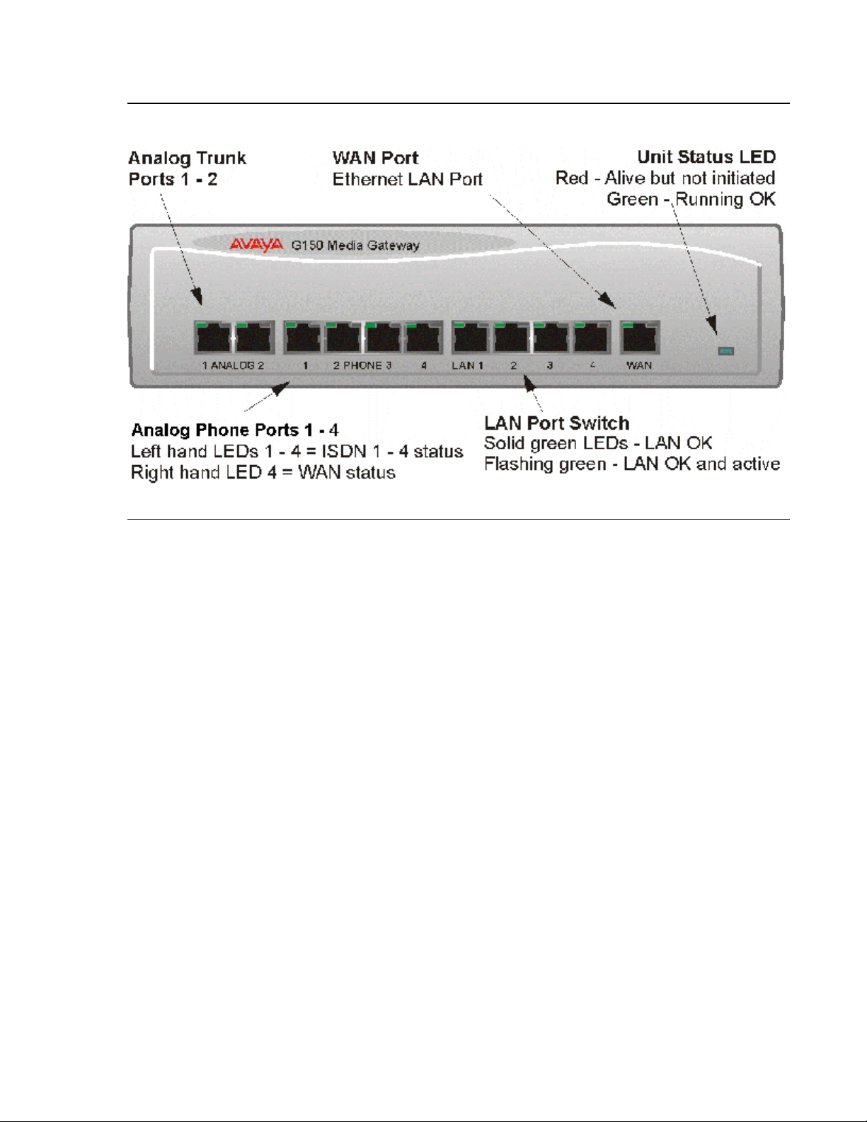
Figure 2: G150 2T + 4A (4 VoIP) front view
Note:
G150 Models
Port connections
● Analog Trunk Port s: These port s are used fo r connecti on to st andard analog t runks (loop
start). Using standar d structu red wir ing, t hese RJ45 port s can be ext ended to the requi red
trunk sockets. In the event of mains power supply failure, Analog Port 2 is automatically
switched to Phone port 1.
● Analog Telephone Ports: These ports are used for connection to standard analog
telephones, fax machines and modems. Using standard structured wiring, these RJ45
ports can be extended to the required telephone location. When telephones are equipped
with line cords that termina te in RJ11 plugs, then pin-to-pin RJ11/RJ45 adapters should be
used.
Note: Fax/modem ports are used with local G150 trunks onl y.
● LAN Ports: These are LAN 10/100Mbps Layer 2 Ethernet switches and are used for PC
and server connectivity. They have Auto MD1/MD1X capability and hence avoid the need
for LAN crossover cables when connecting to a hub. They can also be used to connect to
IP telephones (Avaya 4600 IP series). LAN ports allow information relating to incoming
and outgoing telephone call s to be f or warded to PC based appli cati ons. They als o provi de
access to the router functionality/configuration of the G150 platform for both data and
Voice over IP (VoIP) calls. Within the configuration software application (Manager), these
ports are referred to as LAN1.
Issue 1 June 2005 27
Page 28
Installing Hardware for the G150 Media Gateway
● WAN Port: This is a 10/100Mbs Ethernet LAN port for connection to a WAN (e.g. DSL).
Within the configuration software application (Manager), thi s port is referred to as LAN2.
Cables
G150 is supplied with one red CAT 5E cable. For Port Pinouts and Cables, refer to Appendix
A: Technical Data.
Back Panel of the G150 (all models)
All models of the G150 have the same configuration when viewing the back of the control unit.
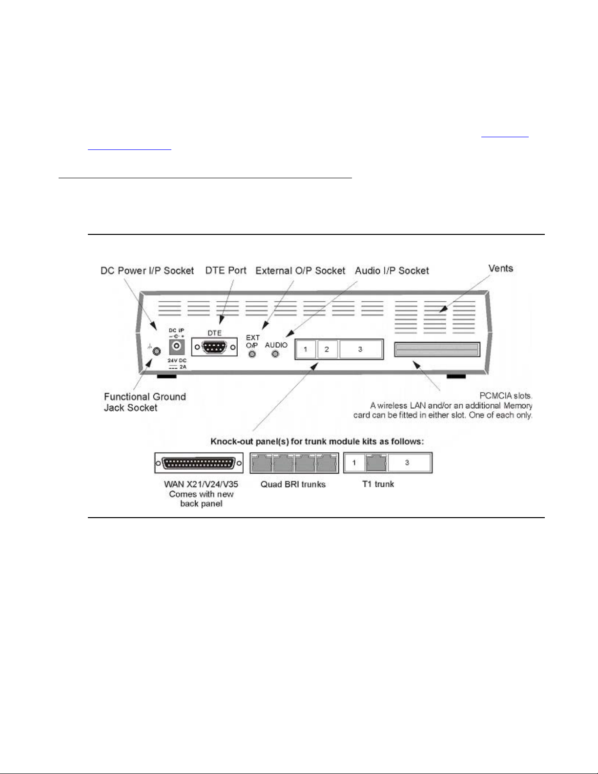
Figure 3: G150 back view
Connections
● External O/P Socket: Not used with the G150.
● DC Power I/P Socket: Socket for the external 24V DC unregulated power supply.
● DTE Port: A 9-way D-type socket. Used for applicati ons Licence Key devi ce (Dongl e) and
connection to PCs, Servers and EFTPOS terminals.
28 Installation and Configuration of the G150 Media Gateway
Page 29

G150 Models
!
● WAN Slot: This slot support s a s ingle synchronous voi ce/dat a PSTN W AN inte rface of the
following types:
- G150 Quad BRI Card (Euro ISDN)
- G150 WAN Expansion Card (V35/V24/X21)
- G150 T1/PRI Card (23B+1D or 24B trunks)
● PCMCIA slots: Used for a Wireless LAN card when using the system as an Access Point
for 802.11b support of a wireless data application. The second PCMCIA slot may be used
to house a 64M flash memory card for providing a TFTP server.
● Audio I/P Socket: Not used with the G150.
● Functional Earth Socket: A single 3.5mm jack socket with all 3 pins connected to ground.
For use in areas with high lightning and/or ESD. Connect a 3.5mm jack plug (not
supplied), fitted with a green sleave 14swg wire, to the buildings approved earth point
(must conform to local grounding (earthing) regul ations).
CAUTION:
CAUTION: This is not a protective ground poi nt. The uni t is al so earth ed via the power cable
(through the lump in line PSU).
WAN Interface Cards
These WAN interface cards provide for the ability of customers to expand their voice PSTN
trunk options to include BRI and T1/ISDN PRI. The local serving PSTN provider may offer one
or the other of these interfaces in the giv en country of destination for this gateway. The WAN
slot in the back panel of the G150 supports voice/data PSTN WAN interface of the following
types:
● G150 ISDN Basic Rate Expansion Card
- SAP code: 700352412
● G150 WAN Expansion Card
- SAP code: 700352347
● G150 T1/ISDN PRI 24 Expansion Card
- SAP code: 700352354
The following wireless LAN card fits into the PCMCIA slot in the back of the G150:
● G150 Wireless LAN Card
- SAP code: 700352420
T1 WAN interfaces are capable of supporting robbed bit service, ISDN Primary Rate service
both in full T1 and FT1 modes for both voice and data WAN servi ces. In the North Ameri can T1
interface, this is capable of supporting up to twenty-three 64 Kbp s channels for PRI and
twenty-four channels for robbed bit signaling.
Issue 1 June 2005 29
Page 30

Installing Hardware for the G150 Media Gateway
Note:
Data services are for use with local G150 analog phone sets only.
Note: QSIG is not supported on G150.
G150 ISDN Basic Rate
This WAN card offers a quad interface consisting of 4 individual 4-wire ISDN ST interfaces.
ISDN Basic rate provides 2 x 64K speech channels using Q.931 signaling and CRC error
checking. Both point to point and point to multipoint operation is supported. Multipoint lines
allow multiple devices to share the same line, however, point-to-point is the preferred mode.
Basic rate supports the foll owing services:
● Dialed Number Identification (DNIS) - Prov ides a str ing of digi t s t o the G150 depending o n
the number dialed by the incoming caller.
● Automatic Number Identification (ANI) - Provides G150 with the incoming caller’s phone
number.
● Multiple Subscriber Number - Provides up to 10 numbers for routing purposes. This
services is usually mutually exclusive with the DDI/DID service.
G150 WAN Expansion Card
The WAN expansi on card is f itted to the G150 t o provide a si ngle W AN connec tion (X21, V35 o r
V24 via a 37-way D-type socket). Line speeds up to and including 2Mbp s are supported on the
interface. The carrier providing the line dicates the actual operating speed. In some territories,
the maximum speed may be 1.544M.
G150 T1 - North American T1 with In-Band Signaling Support
T1 Primary Rate provides up to 24 56K channels over a 1.54M circuit.
Each 64Kbps channel of the T1 trunk can be independently configured to support the following
signaling emulations (with handshak e types of immediate, delay or wink):
● Loop-Start
● Ground-Start
● E&M Tie Line
● E&M DID
● E&M Switched 56K
● DID - Channels configured for DID/DDI support incoming calls only. The carrier or central
office will provide the last X digits that were dialed to be used for call routing.
● Wink-Start
30 Installation and Configuration of the G150 Media Gateway
Page 31

Where available from the central office, G150 T1 trunks support the following services:
Note:
● Dialed Number Identification (DNIS) - Prov ides a str ing of digi t s t o the G150 depending o n
the number dialed by the incoming caller.
● Automatic Number Identification (ANI) - Provides G150 with the incoming caller’s phone
number.
G150 PRI - North American Primary Rate Interface (ISDN)
G150 supports Primary Rate trunks on 5ESS or DMS100 central of fice switches provided by
AT&T, Sprint, WorldCom and other local telcos. Channels can be pre-configured for the
supported services or negotiated on a call-by-call basis.
G150 also supports the Calling Name service over Primary Rate trunks, 4ESS and National
ISDN 2 (NI2) signalling modes.
Using the PCMCIA slot for Wireless Access (for dat a applications)
To use the G150 as a wireless access point, the G150 must be fitted with a Wireless LAN card
and the Wireless LAN Access Point license key.
G150 Models
The G150 supports the following in relation to wireless access capabities:
● 2.4 GHz to 2.5 GHz band
● Automatic fallback 11Mbits/s, 5.5Mbits/s, 2Mbits/s or 1Mbits/s
● IEEE 802.11 and IEEE 802.11b compliance
● Wireless Fidelity Wi-Fi™ compliance
● Interoperable with other 802.11b compliant devices
● WEP or RC4 security
● Range up to 550M (1750 ft)
All G150 models can be configured to become Wireless LAN acc ess points by inserting an
802.11B PCMCIA card in a dedicated twin slot on the back panel of the G150. An access point
acts as a hub in a wireless network providing connectivity between devices in the vicinity. In
ideal conditions, a range of up to 550M (1750 ft) is achievable; although this range will be
decreased if walls and other obstacles are present. See Table 4
. G150 can be used with
external access points where loca l condit ions imp ai r coverage and addi tional access point s are
needed to cover the black spots.
Note: G150 does not support QoS on WiFi connections using the 802.11b PCMCIA
card.
Issue 1 June 2005 31
Page 32

Installing Hardware for the G150 Media Gateway
The G150 wireless network can be secured against intrud ers using either the Wired Eq uivalent
Privacy (WEP) or RC4. WEP uses 64 bit encr yption key and RC4 uses a 128 bi t encrypti on key.
Only devices with a matching security key can participate in the network. G150 complies to the
IEEE 802.11 and IEEE 802.11b st andards me eting th e Wireless Ether net Comp atibi lit y Alli ance
(WECA) Wireless Fidelity Wi-Fi™ requirements for interoperability.
Table 4: G150 WiFi Range Specifications
RANGE
11 MBIT/S 5.5 MBIT/S 2 MBIT/S 1 MBIT/S
(METERS/FT)
Open 160m (525 ft) 270m (885 ft) 400m (1300 ft) 550m (1750 ft)
Semi-open 50m (165 ft) 70m (230 ft) 90m (300 ft) 115m (375 ft)
Closed 25m (80 ft) 35m (115 ft) 40m (130 ft) 50m (165 ft)
Receiver
-82 -87 -91 -94
Sensitivity dBm
Delay Spread
65ns 225ns 400ns 500ns
(at FER of
<1%)
Quality of Service (QoS)
The G150 supports two IP routi ng queu es on each of i t s WAN ports (Ethernet WAN on the front
panel and the optional WAN interface on the back panel). One routing queue is dedicated to
Voice Traffic, the second to any other data. Voice traffic and signaling can be independently
marked using Differentiated Services. This ensures that calls in-progress take priority over call
signaling and other traf fic on slow bandwid th links. When operating over Fra me Relay, G150 will
mark non-voice traffic that exceeds the committed information rate as discard to ensure voice
receives priority. Traff ic that is bei ng sent over a G150 Ethernet i nterface is Di ffServ mark ed, but
treated as a single queue.
Silence suppression allows the best use of available bandwidth. Silence suppression works by
sending descriptions of the background noise, rather t han the actual noise itsel f, during gaps in
conversation, thereby reducing the packet size needed.
Large packets traveling over lo w bandwid th links such as F rame Relay or PPP connections are
also fragmented to allow voice packet to be interleaved.
Supported QoS related standards
● Silence Suppression
● Frame Relay Discard Eligibility
● Local End Echo Cancellation 25ms
● Out-of-band DTMF
32 Installation and Configuration of the G150 Media Gateway
Page 33

● 5 frames of jitter buffer
● RFC 2507, 2508, 2509 - Header Compression
● RFC 2474 - DiffServ, Type of service field configurable
● RFC 1990 - PPP Fragmentation
● RFC 1490 - Encapsulation for Frame Relay
● RFC 2686 - Multiclass Extension to Multilink PPP
● FRF 12 - Frame Fragmentation
G150 Models
For information on configuring QoS on the G150, see DiffSer ve Settings for VoIP Calls
Chapter 3.
Typical Configurations
The following sections illustrate two t ypical scenar ios for usage of the por t s on the G150. These
are configuration examples only and are intended to demonstrate the flexibility of the G150.
Sample Small Branch Office Setup
A small branch office that requi res the following connectivity:
● Two analog trunks
● One IP WAN connection to the Communication Manager (shown as a DSL connection in
Figure 4
● Two analog telephones & one fax
● Up to four IP telephones
● One printer
● Voicemail at company HQ
.
in
Solution (for this sample scenario only)
● G150 2T +4A (4 VoIP)
● Wireless LAN card - 802.11b (Optional)
● Licence Key Device & Access Point RFA
● Up to 4 x IP trunks via 10/100 WAN port
● 2 x Analog trunks for local calls or fall-back
● 4 x IP phones (each with 1151B1 PoE PSU)
● 1 x spare analog extension port
Issue 1 June 2005 33
Page 34

Installing Hardware for the G150 Media Gateway
Figure 4: Sample of a Small Branch Office Setup
A Sample Medium Branch Office
Connectivity example for a medium-sized branch office:
● 2 analog trunks
● 1 IP WAN connection
● 2 fax machines
● 6 IP phones
● Workgroup switch for data & voice devices
● Voicemail at company HQ
34 Installation and Configuration of the G150 Media Gateway
Page 35

Sample Solution
● G150 4T + 4A (16 VoIP)
● IP trunks via 10/100 WAN port
● 2 analog trunks for local calls or fallback
● 3rd party LAN switch with QoS
● 6 IP phones (each with 1151B1 PoE PSU)
● Capacity for 10 additional IP phones
● 8 DS ports for future use. Not currently supported on the G150.
Figure 5: Sample of a Medium Branch Office Setup
G150 Models
Issue 1 June 2005 35
Page 36

Installing Hardware for the G150 Media Gateway
Note:
Preparing for Installation
This section reviews the requirements for installing an G150 system. You must meet these
requirements for the system to operate saf e ly and in the intended manner.
This section covers :
● Tools & Parts Required
● Space requirements
● Environmental requirements
● Power Supply Requirements
Tools & Parts Required
General :
● Pozidrive No. 1 screwdriver for removal of unit covers.
● Cutte r/knife for cable ties.
● Cable ties
● Pozidrive No. 4 screwdriver for Analog Trunk 16 expansion module grounding post.
Note: In addition, ensure that you have sufficient cables that are not supplied with the
modules, e.g. Line Cords for structured cabli ng and power supply cables.
Programming :
These are the tools required for programming of a newly installed G150 system.
● PC running Windows 98 (2nd Edition), 2000 Professional (SP2) & Server (SP2), XP
Professional Server & XP Home, NT4 Workstation (SP6) & NT4 Server (SP6a) or 2003
Server:
Intel Pentium ll 333Mhz or faster, 100MB HD space, CD-ROM drive, COM port, terminal
emulation (e.g. HyperTerminal) and a super VGA Monitor (set to 1024 by 768). PC should
have a LAN card with either a fixed IP address (allocat ed by your system administrator) or
be using DHCP to obtain an IP address.
● IP Cat. 5E patch cable (red - supplied with system).
● G150 Administration CD.
● G150 Feature Key device (Dongle).
36 Installation and Configuration of the G150 Media Gateway
Page 37

Space requirements
Check that the planned location meets the following requirements.
Height : 76mm (3 inches)
Width : 255mm (10 inches)
Depth : 235mm (9.3 inches)
● Where a G150 is free standing, allow a minimum clearance of 62mm (2.5 inches) either
side for cable trunking.
● Check there is suitable lighting for installation, system programming and future
maintenance.
● Check that there is sufficient working space for installation and future maintenance.
● Ensure that likely activities near the system will not cause any problems, e. g. access to
and maintenance of any other equipment in the area.
Preparing for Installation
Environmental requirements
The planned location must meet the following requirements:
● Check that the area is a well ventilated area, having a temperature range of 0*C to +40*C
and a humidity range of 10% to 95% non-condensing.
● Check there are no flammable materials in the area.
● Check there is no possibility of flooding.
● Check that no other machinery or equipment needs to be moved first.
● Check that it is not an excessively dusty atmosphere.
● Check that the area is unlikely to suffer rapid changes in temperature and humidity.
● Check for the proximity of strong magnetic fields, sources of radio frequency and other
electrical interference.
● Check there are no corrosive chemicals or gasses.
● Check there is no excessive vibration or potential of excessive vibra tion, especially of the
cabinet mounting surface.
● USA only: Telephones may not be installed in a building that is separate from the one
housing the G150.
Issue 1 June 2005 37
Page 38

Installing Hardware for the G150 Media Gateway
!
IMPORTANT SAFETY INSTRUCTIONS
When using your telephone equipment, basic safety precaut ions should always be followed to
reduce the risk of fire, electric shock and injury to persons, including the following:
● Do not use this product near water, for example, near a bath tub, wash bowl, kitchen sink
or laundry tub, in a wet basement or near a swimming pool.
● Avoid using a telephone (other than a cordl ess type) duri ng an electr ical s torm. There may
be a remote risk of electric shock from ligh tning.
● Do not use the telephone to report a gas leak in the vicinity of the leak.
● Use only the power cord and batteries indicated in this manual. Do not dispose of batteries
in a fire. They may explode. Check with local codes for possible special disposal
instructions.
Power Supply Requirements
G150 should only be connected to a clean power supply or to a UPS with 3-pin connectors
including earth.
CAUTION:
CAUTION: The Lump-in-Line PSUs supplied with each G150 module must only be
connected to a 50/60Hz, 100-240V power source.
UPS Equipment :
The use of UPSs to support the G150 system during mains power failure is highly
recommended. Such equipment also provides mains conditioning. Contact Avaya for details of
preferred and tested suppliers and models.
38 Installation and Configuration of the G150 Media Gateway
Page 39

Functional Ground
!
This is an optional feature. Functional grounding protects t he component in which it is attached
to. The functional ground jack socket on the back of the G150 can be connected by following
the instructions below.
CAUTION:
CAUTION: This functional ground is not a protective gr ound.
To connect the functional ground:
1. Use a 3.5mm Jack Plug (not supplied with kit) fitted with a suitable length of #14 AWG
(minimum) solid insulated cable. The sleeve must not be green/yellow.
2. Insert this Jack Plug into the Fun ctional Ground Jack Socket (i n the back of the G150 Media
Gateway).
3. Connect, using a fastening that satisfies local regulations, the other end of the #14 AWG
wire to the approved ground, such as building steel or an earthed metal cold water pipe.
Installing a New G150 System
Installing a New G150 System
Initial Assembly - Overview
Prior to initial assembly and mounting (shelf/wall mounting or free standing) of your system,
check that:
● The required Trunk Interface Modules have been installed and are of the correct country
variant type.
● Where structured cabling is to be used it has been installe d, conforms to all local
regulations and is clearly labeled.
To start assembling the G150 Media Gateway, do the following:
1. Mount the G150 module in its final location.
2. Run the Lump-in-Line PSU cable back to the switchable mains supply but do not
switch-on or connect the PSU to the G150.
3. Connect the Tr unks, using BRI ISDN Cables, to your provider’s trunk sockets.
4. Connect the Phone Port s, using Li ne Cords, to t he structured cable socket s or dire ctly to the
appropriate telephone. Note that in default, the lowest port number corresponds to the
lowest extension number (201 by default).
Issue 1 June 2005 39
Page 40

Installing Hardware for the G150 Media Gateway
!
!
!
5. Install all telephones in their appropriate locations. For wall mounting, see G150 Shelf/Wall
Mounting below.
6. Connect your PC LAN Port to one of the LAN Ports on the front of an G150 using a LAN
Cable.
7. Switch on the ac mains supply.
8. The Manager software (provided on the Administrator CD) can now be installed on the PC.
For detailed instructions on installing Manager, see The Manager Application Software
Chapter 3.
G150 Shelf/Wall Mounting
The G150 is not designed for rack mounting. All vari ant s of the G150 can be either shel f or wall
mounted. Four retaining slots (item 1 below) enable the G150 control unit to be mounted and
secured either:
● Horizontally on a shelf - leaving suf fici ent sp ace for the cabling at bot h front and r ear of the
unit.
in
● Vertically fro m a wall - with the front panel facing down only.
Figure 6: Wall Mounting Sample
A Z-bracket (item 2 below, supplied with unit) is used to retain the G150 control unit in position.
CAUTION:
CAUTION: The Z-bracket must not be used as the sole mounting fixture.
CAUTION:
CAUTION: When mounting vertically, the weight of the control unit must be held by the two
No. 8 Panhead screws located into the retaining slots.
CAUTION:
CAUTION: When mounted vertically, the air vents (on the rear panel of the G150) must be
on the top surface. e.g. item 2 below must be fitted above the unit.
40 Installation and Configuration of the G150 Media Gateway
Page 41

Installing a New G150 System
To mount the G150:
1. Drill two holes 16cm apart (hori zontally or vertically - see Caution above).
Using suitable wall f ixings (wall plugs), i nsert two No.8, Panhead scr ews (25mm long min. -
not supplied) into wall leaving approximately 1cm proud of wall.
2. Fit the Z-bracket (item 2 below) onto the base of the unit using the M3 Plastite self tappi ng
screw supplied.
3. Slide the G150 unit onto the two screws, locating them into the two retaining slots (item 1
below).
4. Mark the position of the retaini ng screw (No. 8 Panhead or similar - not supplied) that is to
be used through the slot of the Z-bracket .
5. Remove the unit from the wall and, using suitable wall fixings , drill a hole for the Z-bracket
retaining screw.
6. Re-position the G150 and secure with a No. 8 Panhead (or similar) through the slot of the
Z-bracket.
Figure 7: G150 for Mounting
Issue 1 June 2005 41
Page 42

Installing Hardware for the G150 Media Gateway
Installation of Integral Modules
A G150 can be fitted with a WAN module, a quad BRI module or a PRI/T1 module. In addition,
either or both the o ptional PCMCIA cards (Memory and/or Wireless LAN) can be fi tted. All items
referenced in the procedural steps below are in relation to Figure 8
Procedure:
1. To add either a wireless LAN or additional Memory card you do not need to de-assemble a
module, simply insert the card (item 1) into either of the PCMCIA slots in the rear panel .
These slots are universal , hence th e location do es not matt er. Only one Memory or wireless
LAN card can be fitted.
2. To add a WAN or BRI or PRI/T1 module:
Remove the top cover (item 2) by removing th e four retai ning screws (two eit her side - items
3) and proceed as follows.
3. Remove the rear panel (item 4).
Only discard if a WAN module is being fitted (see step 4 below).
.
On the rear panel, press out all of the knock-out panels (item 5) for a Quad BRI or just the
middle one for a PRI/T1.
● Plug the trunk board (item 7) onto it’s sockets and stand-off hex. pillars.
● Ensure that the trunk module sockets slot into the hole in the rear panel (item 5).
Secure the trunk board in position and with the two snap-in spacers.
● Mount the existing rear panel s if a WAN module is not being fitted .
If a WAN module is being fitted, see the next step.
4. To add a WAN module:
● Remove and discard the rear panel (item 4).
● Fit the new rear panel (supplied with the WAN module and has a slot for WAN port
27-way D-type, item 4).
● On the rear panel, press out all of the knock-out panels (item 5)
● Mount WAN module (item 7) in position and secure with the two snap-in spacers.
42 Installation and Configuration of the G150 Media Gateway
Page 43

Figure 8: Installing Integral Modules
Installing a New G150 System
You have now completed the initial hardware installation of the G150 Media Gateway.
Issue 1 June 2005 43
Page 44

Installing Hardware for the G150 Media Gateway
44 Installation and Configuration of the G150 Media Gateway
Page 45

Chapter 2: Communication Manager Administration
Note:
for the Avaya G150 Media Gateway
The Communication Manager software on the media server (DEFINITY Server SI or CSI, or an
S8300, S8500, S8700, or S8710 Media Server) must be configured, in accordance with the
Communication Manager Remote Office Feature group, to recognize, communicate with, and
control the Avaya G150 Media Gateway. Use the following instructions to help you configure
and administer the G150 Media Gateway within Communication Manager software.
Note: Whenever you make substantial changes to the server, such as entering new
stations and trunks, it is a good idea to save translations both before and after.
Sample configuration
A sample configuration is used for illustration purposes in thi s chapter. In this configuration, the
media server (S8500 or S8700-series) and central gateway (G650, SCC1 , MCC1, CMC1, or
G600) have the following characteristics:
● Server with name mainS8500HQ physically located in Chicago
● Administered in Network Region 1, which uses Codec 1 as primary
● Administered with location of 1
● Gateway with at least one TN799 C-LAN and at least one TN2302 IP Media Processor
The G150 Media Gateway with name
● Physically located in Denver
● Administered in Network Region 3, which uses Codec 2 as primary
● Administered with location of 2
remoG150denver has the following characteristics:
Issue 1 June 2005 45
Page 46

Communication Manager Administration for the Avaya G150 Media Gateway
Figure 9: G150 sample configuration
Network Region 1
(with codec 1 as primary)
Server
(mainS8500HQ)
Location 1
Central
Gateway
C-LAN
IP MedPro
LAN
Administer cu sto me r optio ns
Instructions
IP-routed
WAN
LAN
Location 2
Network Region 3
(with code c 2 as primary)
G150
(remoG150denver)
E1/T1
T.G.
Analog
T.G.
PSTN
Verify that the following fields are administered on the System Parameters Customer Options
screen. An Avaya representative must administer these fields or install a license fil e that
enables the options identified by these fields.
1. Type display system-parameters customer-options and press ENTER to display the
screen. Press NEXT to display page 2.
The system displays Page 2 of the Optional Features screen.
46 Installation and Configuration of the G150 Media Gateway
Page 47

Figure 10: Optional Features screen (page 2)
Note:
display system-parameters customer-options Page 2 of 10
Optional Features
I
P PORT CAPACITIES
Maximum Concurrently Registered IP Stations: 100
Maximum Administered Remote Office Trunks: 10
Maximum Concurrently Registered Remote Office Stations: 10
Maximum Concurrently Registered IP eCons: 0
Maximum Number of DS1 1 Boards with Echo Cancellation:0
(NOTE: You must logoff & login to effect permission changes.)
Administer customer options
Maximum Administered H.323 Trunks: 50
Maximum Administered SIP Trunks:0
Maximum TN2501 VAL Boards:0
Maximum G700/G350 VAL Sources:0
2. Verify that the following fields are enabled:
● Maximum Administered H.323 Trunks:Total number of H.323 (IP) trunks available to
the Communication Manager for communication between all endpoints, port networks,
and remote gateways.
● Maximum Concurrently Registered IP Stations: Total number of IP stations for all
gateways, including G150 Media Gateways, t hat may be re gis tered at one t ime. Must be
less than or
● Maximum Administered Remote Office T r unks: Total number of tr unk group members
equal to the Maximum Ports field on page one of this screen.
for all G150 media Gateways supported by t his media serv er ( a single B-chann el of a T1
or BRI is a trunk group member).
● Maximum Concurrently Administered Remote Office Stations: Total number of
stations (analog) for all G150 Media Gateways su pported by this media server.
Note: If these values are not large enough, you may have to request a new RFA license
file to increase them. Please contact your sales representative.
3. Press NEXT until you see page 4.
The system displays Page 4 of the Optional Features screen.
Issue 1 June 2005 47
Page 48

Communication Manager Administration for the Avaya G150 Media Gateway
Note:
Figure 11: Optional Features screen (page 4)
display system-parameters customer-options Page 4 of x
OPTIONAL FEATURES
Emergency Access to Attendant? y IP Stations? y
Enable ‘dadmin’ Login? y Internet Protocol (IP) PNC? y
Enhanced Conferencing? y ISDN Feature Plus? y
Enhanced EC500? y ISDN Network Call Redirection? y
Enterprise Wide Licensing? y ISDN-BRI Trunks? y
Extended Cvg/Fwd Admin? y ISDN-PRI? y
External Device Alarm Admin? y Local Survivable Processor? y
Extended Cvg/Fwd Admin? y Malicious Call Trace? y
External Device Alarm Admin? y Mode Code for Centralized Voice Mail? y
Five Port Networks Max per MCC? y
Flexible Billing? y Multifrequency Signaling? y
Forced Entry of Account Codes? y Multimedia Appl. Server Interface (MASI)? y
Global Call Classification? y Multimedia Call Handling (Basic)? y
Hospitality (Basic)? y Multimedia Call Handling (Enhanced)? y
Hospitality (G3V3 Enhancements)? y
IP Trunks? y
IP Attendant Consoles? y
(NOTE: You must logoff & login to effect the permission changes.)
4. Verify that the following fields are enabled:
● IP Trunks: y (yes)
● ISDN-BRI T runks: y (yes)
● ISDN-PRI: y (yes)
Note: If these features are not enabled, you may have to request a new RFA license file
to enable them. Please contact your sales representative.
5. Press NEXT to display page 5.
The system displays Page 5 of the Optional Features screen.
48 Installation and Configuration of the G150 Media Gateway
Page 49

Administer customer options
Figure 12: Optional Features screen (page 5)
display system-parameters customer-options page 5 of x
OPTIONAL FEATURES
Multinational Locations? Station and Trunk MSP? n
Multiple Level Precedence and Preemption? Station as Virtual Extension? n
Multiple Locations? y Survivable Remote Processor? n
System Management Data Transfer? n
Personal Station Access (PSA)? y
Posted Messages? n Tenant Partitioning? n
PNC Duplication? n Terminal Trans. Init. (TTI)? y
Port Network Support? y Time of Day Routing? y
Processor and System MSP? n Uniform Dialing Plan? y
Private Networking? y Usage Allocation Enhancements? y
Processor Ethernet? y TN2501 VAL Maximum Capacity? y
Remote Office? y Wideband Switching? y
Restrict Call Forward Off Net? y Wireless? n
Secondary Data Module? y
6. Verify that the following fields are enabled:
● Multiple Locations: y (yes)
● Remote Office: y (yes)
7. Press NEXT until you see page 9.
The system displays Page 9 of the Optional Features screen.
Figure 13: Maximum IP Registrations by Product ID screen
MAXIMUM IP REGISTRATIONS BY PRODUCT ID
Product ID_Rel. Limit Product ID_Rel. Limit Product ID_Rel. Limit
IP_Agent__ ___. 50___ __________ ___. _____ __________ ___. _____
IP_Phone__ ___. 20___ __________ ___. _____ __________ ___. _____
IP_ROMax__ ___. 10___ __________ ___. _____ __________ ___. _____
IP_Soft___ ___. 50___ __________ ___. _____ __________ ___. _____
__________ ___. _____ __________ ___. _____ __________ ___. _____
__________ ___. _____ __________ ___. _____ __________ ___. _____
Page 9 of x
Issue 1 June 2005 49
Page 50

Communication Manager Administration for the Avaya G150 Media Gateway
Note:
8. Verify data for the following fields:
● Product ID: IP_ROMax.
● Limit: Total number of remote office stations for IP_ROMax.
Note: If these values are not large enough, you may have to request a new RFA license
file to increase them. Please contact your sales representative.
Direct IP-IP Audio and IP Hairpinning
Verify that the following fields are administered on the Feature-Related System Parameters
screen.
1. Type change system-p ar ameters f eatures and press ENTER to display the screen. Press
NEXT until you can see page 14.
The system displays Page 14 of the Feature-related System Parameters screen.
Figure 14: Direct IP-IP Audio and IP Hairpinning screen
change system-parameters features page 14
FEATURE-RELATED SYSTEM PARAMETERS
AUTOMATIC EXCLUSION PARAMETERS
Automatic Exclusion by COS? y
Automatic Exclusion Coverage/Hold? y
Automatic Exclusion with Whisper Page? y
Recall Rotary Digit: 2
Password to Change COR by FAC: *
Duration of Call Timer Display (seconds): 3
WIRELESS PARAMETERS
Radio Controllers with Download Server Permission (enter board location)
1. 2. 3. 4. 5.
IP PARAMETERS
Direct IP-IP Audio Connections? y
IP Audio Hairpinning? n
RUSSIAN MULTI-FREQUENCY PACKET SIGNALING
Re-try?
T2 (Backward Signal) Activation Timer (secs):
50 Installation and Configuration of the G150 Media Gateway
Page 51

2. Type y in the Direct IP-IP Audio Connections field to enable shuff li ng.
Note:
Note:
Note:
3. Set the IP Audio Hairpinning field to y (yes) to enable or n (no ) to di sable hairpinning
system-wide. However, see the following note.
Note: For the G150 Media Gateway, IP Audio Hairpinning should be turned off for
optimal performance. However, if most gateways in the Communication
Manager’s configuration, such as G700 or G350 Media Gateways, support
hairpinning, you may want to set IP Audio Hairpinning to y.
Administer IP Boards
Log into the system using a customer login with super-user permission.
Note: The following information is requir ed prior to performing the Communication
Manager administration:
Administer IP Boards
● The IP Address of the G150 Media Gateway
● Security Codes (passwords) for each G150 Media Gateway station.
Instructions
Administer circuit packs
Note: For an S8300 Media Server, skip this procedure. This procedure does not apply.
Verify that the system is administered to provide C-LAN and IP Med ia Processor support.
1. Type display circuit-packs and press ENTER to display the Circuit Packs screen.
The system displays Page 1 of the Circuit Packs screen.
Issue 1 June 2005 51
Page 52

Communication Manager Administration for the Avaya G150 Media Gateway
Note:
Figure 15: Circuit Packs screen (page 1)
display circuit-packs Page 1 of 5
Circuit Packs
Cabinet: 1 Carrier: A
Cabinet Layout: five-carrier Carrier Type: port
Slot Code SF Mode Name Slot Code SF Mode Name
11 TN754 C Digital Line
01: TN767 B DS1 Interface 12 TN754 C Digital Line
02: TN746 B Analog Line 13
03: TN2302 AP IP Media Processor 14
04: TN748 D Tone Detector 15
05: ______ _ 16
06: ______ _ 17
07: ______ _ 18
08: TN799 D Control LAN 19
09: ______ _ 20
10: ______ _
2. Confirm the administration of the C-LAN (TN799) and IP Media Processor (TN23 02). Verify
these board codes are specified in the list of cir cuit packs supported by the syste m.
3. Press NEXT to page through the Circuit Packs screen , if necessary, to locate the TN799
and TN2302 circuit packs.
Note: If administration was not performed on these circuit packs, refer to the
Administration for Network Connectivity for Communication Manager,
555-234-504, document for instructions.
52 Installation and Configuration of the G150 Media Gateway
Page 53

Administer IP Boards
Note:
Note:
Administer IP Addresses and Interfaces
1. Type change node-names IP and press ENTER to display the IP Node Names screen.
The system displays the IP Node Names screen.
Figure 16: IP Node Names screen
change node-names ip Page 1 of 1
IP NODE NAMES
Name IP Address Name
default 0 .0 .0 .0 __________________ ___.___.___.___
remoG150denver 134.23.107.22 __________________ ___.___.___.___
__________________ ___.___.___.___ __________________ ___.___.___.___
__________________ ___.___.___.___ __________________ ___.___.___.___
__________________ ___.___.___.___ __________________ ___.___.___.___
__________________ ___.___.___.___ __________________ ___.___.___.___
__________________ ___.___.___.___ __________________ ___.___.___.___
__________________ ___.___.___.___ __________________ ___.___.___.___
__________________ ___.___.___.___ __________________ ___.___.___.___
__________________ ___.___.___.___ __________________ ___.___.___.___
2. Complete the following fields:
● Name: Assign a unique name to the G150 Media Gateway.
Note: This name must match exactly the name of t he G150 Media Gate way as en ter ed
on the System | SO Gateway | Gateway Name configuration in the G150
Manager. See Identifying the G150 to the Communication Manager
in Chapter 3
for detailed information on configuring this information on the G150 Manager
interface.
● IP Address: Type the IP address associated with the G150 Media Gateway (LAN1
interface). Check with your LAN administrator, if necessary, for the appropriate address.
Note: This IP address must match exactly the IP address of the G150 Media Gateway
as entered on the Configuration screen in the G150 Manager. See Connecting
G150 to the Network & Communication Manager in Chapter 3.
3. Press ENTER to effect the changes.
4. Type list ip-interfaces and press ENTER to display the IP Interfaces screen.
The system displays the IP Interfaces screen.
Issue 1 June 2005 53
Page 54

Communication Manager Administration for the Avaya G150 Media Gateway
Figure 17: IP Interfaces screen (DEFINITY Servers and S8500, S8700, and S8710 Media
Servers)
list ip-interface Page 1 of 4
IP INTERFACES
ON Type Slot Code Sfx Node Name Subnet Mask Gateway Address Rgn VLAN
y C-LAN 01C07 TN799 C clan1_______ 255.255.255.0 192.11.128.254 1__ n
y MEDPRO 01C08 TN2302 AP medpro1_____ 255.255.255.0 192.11.128.258_ 1__ n
_____ ____ ____________ 255.255.255.0 ___.___.___.___ ___ n
_____ ____ ____________ 255.255.255.0 ___.___.___.___ ___ n
_____ ____ ____________ 255.255.255.0 ___.___.___.___ ___ n
_____ ____ ____________ 255.255.255.0 ___.___.___.___ ___ n
_____ ____ ____________ 255.255.255.0 ___.___.___.___ ___ n
_____ ____ ____________ 255.255.255.0 ___.___.___.___ ___ n
_____ ____ ____________ 255.255.255.0 ___.___.___.___ ___ n
_____ ____ ____________ 255.255.255.0 ___.___.___.___ ___ n
Net
Figure 18: IP Interfaces screen (S8300 Media Server)
list ip-interface Page 1 of 4
IP INTERFACES
Net
ON Type Slot Code Sfx Node Name Subnet Mask Gateway Address Rgn VLAN
y PROCR ____ ____ _ procr_______ 255.255.255.0 192.11.128.254 1__ n
_____ ____ ____________ 255.255.255.0 ___.___.___.___ ___ n
_____ ____ ____________ 255.255.255.0 ___.___.___.___ ___ n
_____ ____ ____________ 255.255.255.0 ___.___.___.___ ___ n
_____ ____ ____________ 255.255.255.0 ___.___.___.___ ___ n
_____ ____ ____________ 255.255.255.0 ___.___.___.___ ___ n
_____ ____ ____________ 255.255.255.0 ___.___.___.___ ___ n
_____ ____ ____________ 255.255.255.0 ___.___.___.___ ___ n
_____ ____ ____________ 255.255.255.0 ___.___.___.___ ___ n
_____ ____ ____________ 255.255.255.0 ___.___.___.___ ___ n
5. Ver ify that the ON field cont ains y (yes) to enable TN799, TN2302, or PROCR interfaces for
the media server.
54 Installation and Configuration of the G150 Media Gateway
Page 55

Administer IP Boards
Note:
6. For DEFINITY Servers or S8500, S8700, or S8710 Media Servers only, verify that the
C-LAN and IP Media Processor resources are allocated and assigned in the Net Rgn
(Network Regions) field for optimal suppor t of G150 Media Gateway units. Ideally, the
resources are in the same network region as the G150 Media Gateway.
For an S8300 Media Server only, verify that the Processor (PROCR) is assigned in the Net
Rgn (Network Regions) field for optimal sup port of G150 Media Gateway units. Ideally, the
resources are in the same network region as the G150 Media Gateway.
Note: The IP addresses for a C-LAN (S8500 and S8700-series Media Servers) or
PROCR ((S8300 Media Server) must match exactl y the IP address of the primary
gatekeeper as entered on the Configuration screen in the G150 Manager. See
Gatekeeper Registration
in Chapter 3.
7. If any changes are necessary, exit the list IP Interfaces screen. Typ e change ip-interfaces
<slot_number_of_circuit_pack> (for DEFINITY Servers or S8500, S8700, or S8710
Media Servers) or change ip-interfaces procr (for an S8300 Media Server) and press
ENTER to display the IP Interfaces screen.
Figure 19: Change IP Interface screen
change ip-interface 02c08 Page 1 of 1
IP INTERFACES
Type: CLAN ETHERNET OPTIONS
Slot: 02c08 Auto? n
Code Sfx: TN799 D Speed: 100Mbps
Node Name: clan1xxxxxxxxxx Duplex: Full
IP Address: 123.456.789.012
Subnet Mask: 255.255.255.0
Gateway Address: 192.11.128.254
Enable Ethernet Pt? y
Network Region: 1
VLAN: n
Number of CLAN Sockets Before Warning: 400
8. Make appropriate changes.
Issue 1 June 2005 55
Page 56

Communication Manager Administration for the Avaya G150 Media Gateway
Note:
Administer Ethernet data module
Note: For an S8300 Media Server, skip this procedure. This procedure does not apply.
You need to add an Ethernet data module on the Data Module sc reen for the C- LAN connection
if one is not already present. However, to add an Ethernet data module, you must first disable
the Ethernet port of the C-LAN connection, then enable the Ethernet port after you have added
the Ethernet data module.
1. Type change ip-interfaces <slot_number_of_circuit_pack> (for DEFINITY Servers or
S8500, S8700, or S8710 Media Servers) or change ip-interfaces procr (for an S8300
Media Server) and press ENTER to display the IP Interfaces screen.
2. Type n in the Enable Ethernet Pt field.
3. Press Submit to save your changes.
4. Type add data-module next and press ENTER to display the Data Module screen.
The system displays the Data Module screen.
Figure 20: Data Module screen
add data-module next Page 1 of X
DATA MODULE
Data Extension: 2377 Name: ethernet on link 2
Type: ethernet
Port: 01c17_
Link: 2
Network uses 1’s for broadcast addresses?: y
5. Complete the following fields:
● Type: Type Ethernet.
● Port: Type the slot location of the C-LAN card and 17 as the port number.
● Link: The link must be in the range 1 – 64 for DEFINITY Server SI and the S8500,
S8700, and S8710 Media Servers, or 1 – 8 for DEFINITY Server CSI.
6. Press Submit to save your changes.
7. Return to the Change IP Interfaces screen for the C-LAN circuit pack, and type y in the
Enable Ethernet Pt. field.
56 Installation and Configuration of the G150 Media Gateway
Page 57

Administer CODECs
The IP CODEC Set screen is used to establish an audio CODEC preference list, to associate
silence suppression, and to assign frame and packet si ze attributes to each CODEC. You can
specify up to 7 sets of different CODECs. By default, all the sets have one CODEC G.711
(µ-law) with no silence suppression and packet size 20ms in Communication Manager.
CODEC bandwidth usage
The bandwidth usage of the available CODECs help determine which CODEC(s) you
administer. The signaling information between the G150 Media Gateway and the C-LAN board
(CSI, SI, S8500, S8700, or S8710) or pro cessor inter face (S83 00) consist s of H.323 c ompati ble
messages, which are exchanged over TCP/IP control li n ks. The control links for the analog
phones are permanently establish ed for the lengt h of time that a phone is registe red. There are
two to four additional control links, one that is a shared signaling connection for the analog
trunks, and one signaling connection for ea ch digital trunk. With rough estimation, a n active
signaling channel consumes about 3 Kbps bandwidth.
Administer CODECs
Calculating the amount of bandwidth that voice-encoding-over-IP requires is a little more
complex. The G150 Media Gateway offers a choice of CODECs from the G.711, G.723 (not
recommended), and G.729 family at the point of call registration. The media serv er selects a
particular CODEC at the point of call establishment.
Not including overhead, the CODEC bandwidth required for each call is as follows:
● For G.711: 64 Kbps
● For G.729: 8 Kbps
You multiply the bandwidth for each CODEC by the various packet sizes (expres sed in ms) to
obtain the number of bits of payload per packet for various packet sizes.
Table 5: The Number of Bits of Payload per Packet for Various Packet Sizes
Packet “size” Number of bits of
payload/p acket (G.711)
10 ms 640 80
20 ms 1280 160
30 ms 1920 240
Number of bits of
payload/packet (G.729)
Issue 1 June 2005 57
Page 58

Communication Manager Administration for the Avaya G150 Media Gateway
Note:
Note: The number of bits of payload per pa cket depends on the packet size, but is
independent of the sizes of the individual frames contained in that packet. For
example, a packet size of 60 ms could be referring to six 10 ms frames per
packet, or three 20 ms frames per packet , or two 30 ms frames per packet, etc.
Each packet also includes a 464-bit header (regardless of CODEC and packet size) in addition
to its payload.
So, the following is an expression for the overall one-way bandwidth (assuming no silence
suppression):
● BW = (BW, no overhead) x [(464 + bits payload per packet) / bits payload per packet]
Plugging the number of bits of payload per packet (determined earlier) into this formula yields
the following values for one-way bandwidth (including overhead):
Table 6: Values for One-way Bandwidth (including Overhead) Per Packet Size
Packet size Bandwidth required (Kbps)
for G.711
Bandwidth required (Kbps)
for G.729
10 ms 11 0.4 5 4.4
20 ms 87.2 31.2
30 ms 79.5 23.5
Instructions
1. Type change ip-codec-set <number> and press ENTER to display the screen.
The system displays the IP CODEC Set screen.
Figure 21: IP CODEC Set screen
change ip-codec-set 2 Page 1 of 1
IP CODEC Set
CODEC Set:
Audio Silence Frames Packet
CODEC Suppression Per Pkt Size(ms)
1: G.729A n 2 20
2. G.711MU n 3 30
58 Installation and Configuration of the G150 Media Gateway
Page 59

Administer network regions
Note:
2. Administer a list of audio CODECs, in preference order, that are supported by the G150
Media Gateway. Supported codecs are:
● G.711MU (G.711 Mu-law)
● G.711A (G.711 A-law)
● G.723 (supported, but not recommended)
● G.729a (the commonly used codec between G150 Media Gateways)
3. For each codec, complete the following fields:
● Silence suppression: Type y (yes) or n (no) to enable or disable RTP-level silence
suppression.
● Frames per Pkt: Type a number of 10ms frames, from 2 to 3 (or blank) per packet. The
default for the G.711 codec is two frames. For the G.723 codec, the default is three.
Packet Size is a display-only field.
4. Press ENTER to save the changes.
Administer network regions
Use these procedures to set up network regions, CODEC-set s for a region, QoS values, and
Shuffling.
Multinational locations
If you are deploying G150 Med ia Gat e ways in multiple countries, be sure that the media server
and its IP Media Processor(s) or VoIP engine reside in the network region most central and
appropriate for the G150 Media Gateways. Since the country-speci fic tones assigned to the
VoI P resources are based on where the server’s V oIP resource resides and the tones are used
for all G150 traffic, the server’s VoIP resource should be located in the country requiring the
most commonly-needed tones.
If different G150 Media Gateways must use different country-specific tone p arameters, the
DEFINITY Server CSI/SI or the S8500, S8700, or S8710 medi a server has the abi lity to suppor t
each set of tone parameters with a specifically-assigned IP Media Processor board. In this
case, each processor board is assigned to the specific region that its associat ed G150 Media
Gateway is assigned to. To have multiple I P Media Proces sors assi gned in thi s way, there must
be a unique carrier (MCC1) or cabinet/gateway for ea ch IP Media Processor.
Note: An S8300 Media Server cannot support multiple countr y tone parameters for the
G150 Media Gateways.
Issue 1 June 2005 59
Page 60

Communication Manager Administration for the Avaya G150 Media Gateway
Instructions
To administer the network region for both the server’s central gateway and the G150 Media
Gateway, do the following:
1. Type change ip-network-region <number> and press ENTER to display the IP N e tw o rk
Regions screen.
The system displays the IP Network Region screen.
Figure 22: IP Network Region screen, example for server.
change ip-network-region 1 Page 1 of 19
IP NETWORK REGION
Region: 1
Location: 1 Home Domain:
Name: MainS8500HQ
Intra-region IP-IP Direct Audio: y
AUDIO PARAMETERS Inter-region IP-IP Direct Audio: y
Codec Set: 1 IP Audio Hairpinning? y
UDP Port Min: 2048
UDP Port Max: 65535 RTCP Reporting Enabled? y
RTCP MONITOR SERVER PARAMETERS
DIFFSERV/TOS PARAMETERS Use Default Server Parameters? y
Call Control PHB Value: 46 Server IP Address: . . .
Audio PHB Value: 46 Server Port: 5005
802.1P/Q PARAMETERS RTCP Report Period(secs): 5
Call Control 802.1p Priority: 7
Audio 802.1p Priority: 6 AUDIO RESOURCE RESERVATION PARAMETERS
H.323 IP ENDPOINTS RSVP Enabled? y
H.323 Link Bounce Recovery? y RSVP Refresh Rate(secs): 15
Idle Traffice Interval (sec): 20 Retry upon RSVP Failure Enabled? y
Keep-Alive Interval (sec): 6 RSVP Profile: guaranteed-service
Keep-Alive Count: 5 RSVP unreserved (BBE) PHB Value: 40
2. On the IP Network Region screen, complete the following fields:
● Name: Assign a unique name to the network region of the server’s central gateway.
● CODEC Set: Assign the CODEC set for the Network Region, usually 1.
● Intra-region IP-IP Dir ect Audio: T ype y (yes ) to allow shuf fling bet ween endpoint s in the
server’s region.
● Inter-region IP-IP Direct Audio: Type y (yes) to allow shuffling between server’s
endpoints and endpoints in other network regions.
60 Installation and Configuration of the G150 Media Gateway
Page 61

Administer network regions
Note:
Note:
● IP Audio Hairpinning: Type y (yes) to enable or n (no) to disable hairpinning between
endpoints in the server’s region. Though the G150 Media Gateway performs bet ter
without hairpinning, there may be many other gateways or devices in t he network region
that can benefit from hairpinning.
● UDP Port Min: Type 2048. This is used by the Media Processor for audio RTP/RTCP
connections.
Note: See UDP Port Assignments on page 65 for more information on UDP ports.
● UDP Port Max: Type 65535. This is used by the Media Processor for audio RTP/RTCP
connections.
● Call Control PHB V alue: Assi gn the per hop be havior f or call co ntrol mes sages to agree
with the differentiated services setting in the network. The value 46 is the default and is
required for regions that contain G150 Media Gateways.
● Audio PHB Value: Assign the per hop behavior for audio signals to agree with the
differentiated services setting in the network. The value 46 is the default and is
recommended for regions that pass VoIP traffic with Diff services between
Communication Manager-supported media gateways, including G150 Media Gateways.
3. For DEFINITY Servers or S8500, S8700, or S8710 Media Servers only, if C-LAN and IP
Media Processing resources are shared between regions, go to page 3, which is the Inter
Network Region Connection Management screen. Otherwise, go to Administer multiple
locations on page 67 .
Note: Sharing of resources between or among network regions is allowed only if you
make an entry specifying the CODEC set to be used.
Issue 1 June 2005 61
Page 62

Communication Manager Administration for the Avaya G150 Media Gateway
Figure 23: IP Network Region screen (page 3), example for server
change ip-network-region 1 Page 3 of 19
Inter Network Region Connection Management
src dst codec direct Dynamic CAC
rgn rgn set WAN WAN-BW limits Intervening-regions Gateway
1 1 0
1 2 2 y 256:Kbits 1 ___ ___ ___
1 3 2 y 256:Kbits 1 ___ ___ ___
1 4 2 n 1 ___ ___ ___
1 5 1 n 6 ___ ___ ___
1 6 1 y :NoLimit
1 7 1 y 10:Calls
1 8
1 9
1 10 5 n 1 ___ ___ ___
1 11
1 12
1 13 6 n 1 ___ ___ ___
1 14
1 15
4. Speci fy CODEC sets for your shar ed network re gion s as done in the exampl e above. In the
example, network region 1 will share resources with the following other network regions,
using the specified CODEC sets:
● Network region 1 using CODEC set 1.
● Network regions 3 and 4 using CODEC set 2.
● Network region 10 using CODEC set 5.
● Network region 13 using CODEC set 6.
5. Press ENTER to save the changes.
6. Type change ip-network-region <number> and press ENTER to display the IP N e tw o rk
Regions screen again.
The system displays the IP Network Region screen.
62 Installation and Configuration of the G150 Media Gateway
Page 63

Administer network regions
Note:
Figure 24: IP Network Region screen, example for G150
change ip-network-region 1 Page 1 of 19
IP NETWORK REGION
Region: 1
Location: 2 Home Domain:
Name: remoG150denver
Intra-region IP-IP Direct Audio: y
AUDIO PARAMETERS Inter-region IP-IP Direct Audio: y
Codec Set: 2 IP Audio Hairpinning? y
UDP Port Min: 2048
UDP Port Max: 65535 RTCP Reporting Enabled? y
RTCP MONITOR SERVER PARAMETERS
DIFFSERV/TOS PARAMETERS Use Default Server Parameters? y
Call Control PHB Value: 46 Server IP Address: . . .
Audio PHB Value: 46 Server Port: 5005
802.1P/Q PARAMETERS RTCP Report Period(secs): 5
Call Control 802.1p Priority: 7
Audio 802.1p Priority: 6 AUDIO RESOURCE RESERVATION PARAMETERS
H.323 IP ENDPOINTS RSVP Enabled? y
H.323 Link Bounce Recovery? y RSVP Refresh Rate(secs): 15
Idle Traffice Interval (sec): 20 Retry upon RSVP Failure Enabled? y
Keep-Alive Interval (sec): 6 RSVP Profile: guaranteed-service
Keep-Alive Count: 5 RSVP unreserved (BBE) PHB Value: 40
7. On the IP Network Region screen, complete the following fields:
● Name: Assign a unique name to the network region for the G150 Media Gateway.
● CODEC Set: Assign the CODEC set for the G150 Media Gateway associated with this
Network Region.
● Intra-region IP-IP Dir ect Audio: T ype y (yes ) to allow shuf fling bet ween endpoint s in the
G150 Media Gateway’s region.
● Inter-region IP-IP Direct Audio: Type y (yes) to allow shuffling between G150 Media
Gateway endpoints and endpoi nts in other network regions.
● IP Audio Hairpinning: Type y (yes) to allow, or n (no) to disallow, hairpinning between
G150 Media Gateway endpoints and endpoints in other network regions. Though the
G150 Media Gateway performs better without hairpi nning, there may be many other
gateways or devices in the network region that can benefit from hairpinning.
● UDP Port Min: Type 2048. This is used by the Media Processor for audio RTP/RTCP
connections.
Note: See UDP Port Assignments on page 65 for more information on UDP ports.
Issue 1 June 2005 63
Page 64

Communication Manager Administration for the Avaya G150 Media Gateway
Note:
● UDP Port Max: Type 65535. This is used by the Media Processor for audio RTP/RTCP
connections.
● Call Control PHB V alue: Assi gn the per hop be havior f or call co ntrol mes sages to agree
with the differentiated services setting in the network. The value 46 is the default and is
required for regions that contain G150 Media Gateways.
● Audio PHB Value: Assign the per hop behavior for audio signals to agree with the
differentiated services setting in the network. The value 46 is the default and is required
for regions that contain G150 Media Gateways.
8. For DEFINITY Servers or S8500, S8700, or S8710 Media Servers only, if C-LAN and IP
Media Processing resources are shared between regions, go to page 3, which is the Inter
Network Region Connection Management screen. Otherwise, go to Administer multiple
locations on page 67 .
Note: Sharing of resources between or among network regions is allowed only if you
make an entry specifying the CODEC set to be used.
Figure 25: IP Network Region screen (page 3), example for G150
change ip-network-region 3 Page 3 of 19
Inter Network Region Connection Management
src dst codec direct Dynamic CAC
rgn rgn set WAN WAN-BW limits Intervening-regions Gateway
3 1 2 y 256:Kbits
3 2 1 n 1 ___ ___ ___
3 3 2
3 4 2 n 1 ___ ___ ___
3 5 1 n 6 ___ ___ ___
3 6 1 y :NoLimit
3 7 1 y 10:Calls
3 8
3 9
3 10 5 n 1 ___ ___ ___
3 11
3 12
3 13 6 n 1 ___ ___ ___
3 14
3 15
64 Installation and Configuration of the G150 Media Gateway
Page 65

9. Speci fy CODEC sets for your shar ed network re gion s as done in the exampl e above. In the
example, network region 3 will share resources with the following other network regions,
using the specified CODEC sets:
● Network region 1 using CODEC set 2.
● Network region 4 using CODEC set 2.
● Network region 10 using CODEC set 5.
● Network region 13 using CODEC set 6.
UDP Port Assignments
The G150 Media Gateway uses a single block of UDP ports for audio connections. The defau lt
block starts at 49152. For a given G150 station or trunk port, one UDP port is used for RTP and
the next consecutive UDP port is used for RTCP. For example, with the default block setting,
analog trunk 2 uses 49154 for the RTP/UDP connection and 49155 for the RTCP/UDP
connection.
Administer network regions
Table 7: Port Assignments for Analog Trunks
, identifies the port assignments for the analog
trunks. This table is used in combination wit h one of the f ollowing three t ables, d epending on th e
G150 Media Gateway’s use of a WAN card:
● Table 8: P ort Assignments for Analog Stations (no BRI or PRI WAN card)
● Table 9: P ort Assignments for BRI Trunks and Analog Stations (BRI W AN card)
● Table 10: Port Assignments for PRI Trunks and Analog Stations (T1 WAN card)
The port assignments identified i n each of the three additional tables continues the numbering
sequence from Table 7: Port Assignments for Analog Trunks
.
If the RTP UDP Port information needs to be changed for compatibility with routers which offer
RTP header compression only on ports in certain ranges, it can be updated via the G150
Manager application within System|S0 Gateway|RTP UDP Port Base field.
Table 7: Port Assignments for Analog Trunks
Trunk/Station
Type
RAS
UDP
Port
Q.931
Port
RTP
UDP
Port
RTCP
UDP Port
1st Analog Trunk 6000 7000 49152 49153
nd
Analog Trunk 6000 7000 49154 49155
2
3rd Analog Trunk 6000 7000 49156 49157
th
Analog Trunk 6000 7000 49158 49159
4
Issue 1 June 2005 65
Page 66

Communication Manager Administration for the Avaya G150 Media Gateway
Table 8: Port Assignments for Analog Stations (no BRI or PRI WAN card)
Trunk/Extn Type RAS UDP
Port
Q.931
Port
RTP UDP
Port
RTCP
UDP Port
1st Analog Station 6001 7001 49160 49161
nd
Analog Station 6002 7002 49162 49163
2
3rd Analog Station 6003 7003 49164 49165
th
Analog Station 6004 7004 49166 49167
4
Table 9: Port Assignments for BRI Trunks and Analog Stations (BRI WAN card)
Tr unk/Extn Type RAS UDP
Port
Q.931
Port
RTP UDP
Port
RTCP
UDP Port
1st BRI Trunk Ch 0 6001 7001 49160 49161
st
BRI Trunk Ch 1 6001 7001 49162 49163
1
2nd BRI Trunk Ch 0 6002 7002 49164 49165
nd
BRI Trunk Ch 1 6002 7002 49166 49167
2
3rd BRI Trunk Ch 0 6003 7003 49168 49169
rd
BRI Trunk Ch 1 6003 7003 49170 49171
3
4th BRI Trunk Ch 0 6004 7004 49172 49173
th
BRI Trunk Ch 1 6004 7004 49174 49175
4
1st Analog Station 6005 7005 49176 49177
nd
Analog Station 6006 7006 49178 49179
2
3rd Analog Station 6007 7007 49180 49181
th
Analog Station 6008 7008 49182 49183
4
66 Installation and Configuration of the G150 Media Gateway
Page 67

Administer multiple locations
Table 10: Port Assignments for PRI Trunks and Analog Stations (T1 W AN card)
Trunk/Extn Type RAS UDP
Port
PRI Trunk Ch 0 6001 7001 49160 49161
PRI Trunk Ch 1 6001 7001 49162 49163
PRI Trunk Ch 2 6001 7001 49164 49165
.
.
.
PRI Trunk Ch 23 6001 7001 49204 49205
1st Analog Station 6002 7002 49206 49207
nd
Analog Station 6003 7003 49208 49209
2
3rd Analog Station 6004 7004 49210 49211
th
Analog Station 6005 7005 49212 49213
4
.
.
.
Q.931
Port
.
.
.
RTP UDP
Port
.
.
.
RTCP
UDP Port
.
.
.
Administer multiple locations
The Locations screen allows you to assign time zone and daylight saving rule parameters by
location. Since a G150 Media Gateway will most likely be remot ely located from the media
server, establish location parameters for each G150 region.
Instructions
1. Type change locations and press ENTER.
The system displays the Locations screen.
Issue 1 June 2005 67
Page 68

Communication Manager Administration for the Avaya G150 Media Gateway
Tip:
Figure 26: Locations screen (page 1)
change locations Page 1 of 1
LOCATIONS
ARS Prefix 1 Required For 10-Digit NANP Calls? y
Loc. Name Timezone Rule NPA ARS Attd Loc. Pre- Proxy Sel.
No Offset FAC FAC Parms. fix Rte. Pat.
1. MainS8500HQ + 00:00 1 312
2. remoG150denver- 01:00 1 303 ____ ____ __ ____ _______
3. Lincroft-01____ + 01:00 1 953 ____ ____ __ ____ _______
xxx _______________ _ __:__ __ ___ ____ ____ __ ____ _______
xxx _______________ _ __:__ __ ___ ____ ____ __ ____ _______
2. On the Locations screen, complete the following fields:
● Name: Assign a name for this location, for example, Denver-01.
● Timezone Offset: Enter the time difference in hours and minutes from the media server.
● Rule: Assign the daylight-savings rule that applies to this location.
Tip: Use display daylight-savings rules to see what rules are established for this
system.
● NPA: Type the appropriate area code for the location.
● ARS FAC: Type an ARS FAC for out si de dial ing acc ess if t he n umber shoul d be di f fer ent
than the system-wide ARS FAC.
● Attd FAC: Type an Attendant FAC for attendant access if the number should be different
than the system-wide attendant FAC.
● Loc. Parms: T ype the number of a set of location para meters if the G150 requires unique
parameters such as loss parameters.
● Prefix: If necessary for the G150 locati on, type the prefix that Communication Manager
should insert to the calling number ID for calls made from the location.
● Proxy select route pattern: Not applicable.
3. Press ENTER to effect the changes.
68 Installation and Configuration of the G150 Media Gateway
Page 69

Administer Remote office
Note:
Perform Remote Office administration in Communication Manager on the media server before
registering the G150 Media Gateway endpoints. This administration includes administering the
G150 Media Gateway (Remote Office) and G150 stations.
Instructions
Remote Office
1. Type add remote-office <number> and press ENTER to display the Re m o te O ffice
screen.
The system displays the Remote Office screen.
Figure 27: Remote Office screen
Administer Remote office
add remote-office 6 Page 1 of 1
REMOTE OFFICE 6
Node Name: remoG150denver
Network Region: 22
Location: 2
Site Data: Contact: Joe Smith
Phone: xxx-yyy-zzz
_______________________________
2. Complete the following fields:
● Node Name: Assign a node name to the Avaya G150 Media Gateway. This name must
correspond to the node name used on the IP Node Names screen.
Note: This name must also match exactly the name of the G150 Media Gateway as
entered on the System | SO Gateway | Gateway Name configuration in the
G150 Manager . See Identifying the G150 to the Communication Manager
in
Chapter 3.
● Network Region: Assign the number of a previously administered Network Region for
the G150 Media Gateway. If a Network Region is not assigned, use the region
associated with the C-LAN.
● Location: Assign the number of a previousl y administered Location for the G150 Media
Gateway on the Locations screen. If a location is not specified, this field defaults to 1.
● Site Data: Provide relevant location and site data.
Issue 1 June 2005 69
Page 70

Communication Manager Administration for the Avaya G150 Media Gateway
Note:
3. Press ENTER to effect the changes.
4. Type status remote-office n and press ENTER to verify the addit ion of the G150 Media
Gateway.
The system displays the Remote Offi ce Status screen.
Note: In Figure 28, no stations are actually listed in the Stations Registered field until
the stations are administered. Similarly, no signaling group registration appears
until the signaling group is administered.
Figure 28: Status Remote Office screen
status remote-office 6 Page 1 of 1
REMOTE OFFICE 6
Node Name: remoG150denver IP Address: 134.23 .107.22
Network Region: 22
Location: 2
Trunk Signaling Groups: *5
Stations Registered: 4131 4102 4103 4104 4105 4108
* Signaling group is currently registered
The following fields represent the administration of the Remote Office:
● Node Name
● IP Address
● Network Region
● Location
The Trunk Signaling Groups lists the active signaling groups. In this example, 5 is the
analog signaling group.
The Stations Registered field lists those stations that are registered in named mode.
70 Installation and Configuration of the G150 Media Gateway
Page 71

Set up a signaling group and digital trunk group
Note:
Set up a signaling group and digital trunk group
Note: Important: You will only need to administer an H.323 signaling group or trunk
group between the G150 Media Gateway and the media server if the trunks to
your central office are terminated at the G150 Media Gateway. If you are using
the G150 Media Gateway solely for analog station connectivity, then you will not
need an H.323 trunk or signaling group between the G150 Media Gateway and
the media server.
Each G150 Media Gateway has its own listening port and signaling group for the digital trunks
(T1 or BRI). Set up a new signaling group and trunk group administered for H.323 signaling.
Instructions
Setting up a signaling group
Set up the signaling group for remote office:
1. Type add signaling-group <signaling group number or next> and press ENTER to
display the Signaling Group screen.
Issue 1 June 2005 71
Page 72

Communication Manager Administration for the Avaya G150 Media Gateway
Note:
Figure 29: Signaling Group screen (page 1)
Page 1 of 5
SIGNALING GROUP
Group Number 6__ Group Type: h.323
Remote Office? y Max Number of NCA TSC: 0__
SBS? y Max number of CA TSC: 0___
Trunk Group for NCA TSC: ___
Trunk Group for Channel Selection: 6___
Supplementary Service Protocol: a Network Call Transfer: n
T303 Timer(sec): 10
Near-end Node Name: clan Far-end Node Name: remote office
Near-end Listen Port: 5005 Far-end Listen Port: 7001
Far-end Network Region:
LRQ Required? n Calls Share IP Signaling Connection? y
RRQ Required? n
Media Encryption? y Bypass If IP Threshold Exceeded? y
Passphrase: ________________________
DTMF over IP: out-of-band Direct IP-IP Audio Connections? y
IP Audio Hairpining? n
Interworking Message: Progress
2. On the signaling group screen, complete the following fields:
● Group Type: Type H.323.
● Remote Office: Type y.
● Trunk Group for Channel Selection: Type trunk group number.
● Near-end Node Name: Assign the node name assigned to either the C-LAN that
supports this G150 Media Gateway (S8700, S8710, or S8500 Media Server) or the
S8300 Media Server’s node name.
● Far-end Node Name: Type the node name assigned to the remote office.
Note: This name must match exactly the name of t he G150 Media Gate way as en ter ed
on the System | SO Gateway | Gateway Name configuration in the G150
Manager. See Identifying the G150 to the Communication Manager
● Near-end Listen Port: Type a port number in the 5000-9999 range.
● Far-end Listen Port: Type 7001. This is the dedicated TCP port in the G150 Media
Gateway. For an explanation of the TCP port usage, please refer to Table 8
Table 10
● Calls share IP Signaling Connection: Type y.
.
in Chapter 3.
, Table 9 and
72 Installation and Configuration of the G150 Media Gateway
Page 73

Set up a signaling group and digital trunk group
● Direct IP-IP audio connections: Type y to enable IP call shuffling.
● IP Audio Hairpinning: Type n to disable. This setting prevent s hairpinning f or calls usi ng
this signaling group, even if the server’s system parameters and the network regions
have been enabled for hairpinning.
3. Press ENTER to save your changes.
Setting up a digital trunk group
You can modify an existing trunk group or add a new one.
1. Type add trunk group <trunk group number or next> and press ENTER.
Figure 30: Trunk Group screen (page 1)
add trunk-group 6 Page 1 of 22
TRUNK GROUP
Group Number: 6 Group Type: isdn CDR Reports: y
Group Name: ro-link-denver COR: 1 TN: 1 TAC: 6
Direction: two-way Outgoing Display? n Carrier Medium: IP
Dial Access? y Busy Threshold: 255 Night Service:
Queue Length: 0
Service Type: tie Auth Code? n TestCall ITC: unre
Far End Test Line No:
TestCall BCC: 4
TRUNK PARAMETERS
Codeset to Send Display: 6 Codeset to Send National IEs: 6
Max Message Size to Send: 260 Charge Advice: none
Supplementary Service Protocol: a Digital Handling (in/out): enbloc/enbloc
Trunk Hunt: cyclical QSIG Value-Added: n
Digital Loss Group: 17
Incoming Calling Number - Delete: Insert: Format:
Bit Rate: 1200 Synchronization: async Duplex: full
Disconnect Supervision - In? y Out? n
Answer Supervision Timeout: 0
2. On the Trunk Group screen, complete the following fields:
● Group Type: Type isdn.
● Carrier Medium: Type IP.
● Service Type: Type tie.
● Codeset to Send Display: Type 6.
The default is 6, which supports interoperability with non-Communication Manager
systems.
Issue 1 June 2005 73
Page 74

Communication Manager Administration for the Avaya G150 Media Gateway
Note:
Note:
● Digital Loss Group: Type 17. The default is 13, the Loss Group used for H.323 trunks.
Because this is an H.323 si gnaling group, the media server c annot tell that this ulti mately
terminates in a digit al trunk (f or inst ance, doe s not know if thi s is PRI signali ng or in-band
signaling). Loss group 17 is the correct loss group for digital trunks on the G150 Media
Gateway.
3. Go to the group member assignments screen to associ ate the trunk group wi th the signaling
group.
Figure 31: Group Member Assignments screen
add trunk-group 6 Page 6 of 22
TRUNK GROUP
Administered Members (min/max): 1/2
GROUP MEMBER ASSIGNMENTS Total Administered Members: 2
Port Code 5Fx Name Night Sig Grp
1:IP ro-link-denver 1 6
2:IP ro-link-denver 2 6
3:
4:
5:
6:
7:
8:
9:
10:
4. On the Group Member Assignments screen, complete the following fi elds to add trunk
group members:
● Port: Type IP.
Note: When the screen refreshes, Communication Manager replaces IP with a virtual
trunk number in the format Txxxxxx.
● Sig Grp: Assign the number of the signaling group that provides the s ignaling channel for
this trunk group.
Note: On the G150 Media Gateway, there is a maximum of 23 trunk group members for
each T1 interface and 2 trunk gro up members for each BRI interf ace. All four BRI
interfaces may be deployed.
5. Type change signaling-group <number of signal ing group> and pr ess ENTER to return
to the signaling group screen. See Figure 29
.
74 Installation and Configuration of the G150 Media Gateway
Page 75

Set up a signaling group and an analog trunk group
Note:
Note:
6. In the Trunk Group for Channel Selection field, type the number of the trunk group that
should be associated with this signaling channel.
7. Press ENTER to save your changes.
Set up a signaling group and an analog trunk group
Note: Important: You will need only to administer an H.323 signaling group or trunk
group between the G150 Media Gateway and the media server if the trunks to
your central office are terminated at the G150 Media Gateway. If you are using
the G150 Media Gateway solely for analog station connectivity, then you will not
need an H.323 trunk or signaling group between the G150 Media Gateway and
the media server.
Note: Communication Manager only supports one analog signaling group to an
individual G150 Media Gateway. All trunk group members will be part of this
single managed signaling group. For example, if you ar e deploying any model of
the G150 Media Gateway and have two analog WAN ports connected to the
PSTN network, both of the circuit switched channels utilized are part of this one
signaling group.
Each G150 Media Gateway that uses one or both of its central office loop-start analog trunks
has a listen port, a signaling group, and a trunk group that are uni que to those analog trunks,
and separate from the list en port, signaling group, and trunk group used by the T1 digital trunk.
Set up a new signaling group and trunk group administered for H.323 signaling.
Instructions
Setting up a signaling group
Set up the signaling group for remote office:
1. Type add signaling-group <signaling group number or next> and press ENTER to
display the Signaling Group screen.
Issue 1 June 2005 75
Page 76

Communication Manager Administration for the Avaya G150 Media Gateway
Note:
Figure 32: Signaling Group screen (page 1)
add signaling-group 5 Page 1 of 5
SIGNALING GROUP
Group Number 5 Group Type: H.323
Remote Office? y Max Number of NCA TSC: 0
SBS? n Max number of CA TSC: 0
Trunk Group for NCATSC:
Trunk Group for Channel Selection: 5
Supplementary Service Protocol: a Network Call Transfer? n
T303 Timer<sec>: 10
Near-end Node Name: clan Far-end Node Name: remote office 6
Near-end Listen Port: 5005 Far-end Listen Port:7000
Far-end Network Region: 6
LRQ Required? n Calls Share IP Signaling Connection? y
RRQ Required? y
Media Encryption: n Bypass If IP Threshold Exceeded? n
DTMF Over IP: out-of-band Direct IP-IP Audio Connections? y
IP Audio Hairpinning? n
Interworking Message: PROGress
2. On the signaling group screen, complete the following fields:
● Group Type: type H.323.
● Remote Office: Type y.
● Trunk Group for Channel Selection: type trunk group number.
● Near-end Node Name: Assign the node name assigned to the C-LAN that supports this
G150 Media Gateway.
● Far-end Node Name: Type the node name assigned to the remote office.
● Near-end Listen Port: Type a port number in the 5000-9999 range.
● Far-end Listen Port: Type 7000. This is the dedicated TCP port in the G150 Media
Gateway.
Note: The far-end port must be 7000. The near-end port must be unique; it must be
different from the far-end port.
● Calls share IP Signaling Connection: Type y.
● Direct IP-IP audio connections: Type y to enable IP call shuffling, otherwise type n.
● IP Audio Hairpinning: Type n to disable. This setting prevent s hairpinning f or calls usi ng
this signaling group, even if the server’s system parameters and the network regions
have been enabled for hairpinning.
3. Press ENTER to save your changes.
76 Installation and Configuration of the G150 Media Gateway
Page 77

Set up a signaling group and an analog trunk group
Setting up an analog trunk group
You can modify an existing trunk group or add a new one.
1. Type add trunk group <trunk group number or next> and press ENTER.
Figure 33: Trunk Group screen (page 1)
add trunk-group 5 Page 1 of 22
TRUNK GROUP
Group Number: 5 Group Type: isdn CDR Reports: y
Group Name: ro-anal-den COR: 1 TN: 1 TAC: #05
Direction: two-way Outgoing Display? n Carrier Medium: IP
Dial Access? y Busy Threshold: 255 Night Service:
Queue Length: 0
Service Type: tie Auth Code? n TestCall ITC:unr
Far End Test Line No:
TestCall BCC: 4
TRUNK PARAMETERS
Codeset to Send Display: 6 Codeset to Send National IEs:6
Max Message Size to Send: 260 Charge Advice: none
Supplementary Service Protocol: a Digital Handling (in/out): enbloc/enbloc
Trunk Hunt: cyclical QSIG Value-Added? n
Digital Loss Group: 7
Incoming Calling Number - Delete: Insert: Number Format:
Bit Rate: 1200 Synchronization: async Duplex: full
Disconnect Supervision - In? y Out? n
Answer Supervision Timeout: 0
2. On the Trunk Group screen, complete the following fields:
● Group Type: Type isdn.
● Carrier Medium: Type IP.
● Service Type: Type tie.
● Codeset to Send Display: Type 6.
The default is 6, which supports interoperability with non-Communication Manager
systems.
● Digital Loss Group: Type 7. The default is 13, the loss group used for H.323 trunks.
Because this is an H.323 si gnaling group, the media server c annot tell that this ulti mately
terminates in an analog trunk. Loss group 7 i s the correct loss gr oup for analog tr unks on
the G150 Media Gateway.
3. Go to the Group Member Assignments screen to associate the trunk group with the
signaling group.
Issue 1 June 2005 77
Page 78

Communication Manager Administration for the Avaya G150 Media Gateway
Figure 34: Group Member Assignments screen
add trunk-group 5 Page 6 of 22
TRUNK GROUP
Administered Members (min/max): 1/2
GROUP MEMBER ASSIGNMENTS Total Administered Members: 2
Port Code 5Fx Name Night Sig Grp
1:IP ro-anal-den 1 5
2:IP ro-anal-den 2 5
3:
4:
5:
6:
7:
8:
9:
10:
4. On the Group Member Assignments screen, complete the following fi elds to add trunk
group members:
● Port: Type IP.
● Sig Grp: Assign the number of the signaling group that provides the signaling channel for
this trunk group. Either two trunks (for the G150 2T + 4A model) or four trunks (for the
G150 4T+4A+8DS model) may be designated in this group.
5. Type change signaling-group <number of signal ing group> and pr ess ENTER to return
to the signaling group screen. See Figure 32
6. In the Trunk Group for Channel Sel e ction field, type the number of the trunk group that
should be associated with this signaling channel.
7. Press ENTER to save your changes.
Administer loss plan
To administer a loss plan, see Appendix G: Loss Plan Settings.
These are used to optimize the transmission pat h gain/loss for a given communication call.
.
78 Installation and Configuration of the G150 Media Gateway
Page 79

Add phones to remote office location
Note:
When administering a remote office telephone, the extension you add must match your dial
plan.
The following telephones may be added to a remote office location:
IP telephones Analog telephones
4601 6211
4602 6219
4602SW 6221
4606 Interquartz
9330-AV
4610SW Interquartz
9335-AV
Add phones to remote office location
4612
4620
4620SW
4624
Note: The extension numbers and security codes you enter in Communication
Manager must exactly match the extensions and passwords you enter in th e
G150 Manager . See Extension Numbering within G150
and Setting up Users in
Chapter 3 for details on configur ing this information on the G150 Manager
interface.
Add an analog telephone
1. Type add station <extension number> and press ENTER to display the Station screen.
The system displays the Station screen.
Issue 1 June 2005 79
Page 80

Communication Manager Administration for the Avaya G150 Media Gateway
Note:
Figure 35: Station screen (page 1)
add station 4101 Page 1 of 4
STATION
Extension: 4101 Lock Messages? n BCC: 0
Type: 6210 Security Code: 1234567 TN: 1
Port: x Coverage Path 1: ___ COR: 1
Name: Remote main Coverage Path 2: ___ COS: 1
Hunt-to-Station: Tests: y
STATION OPTIONS
Loss Group: _ Message Waiting Indicator: none
Off Premises Station:
Remote Office Phone? y
2. Complete the following fields:
● Type: Assign the set type associated with the terminal.
● Port: Type x.
● Security Code: Assign a security code/password that is used to validate G150 Media
Gateway registration using this extension. The maximum length of the security code/
password is seven digits.
Note: The security code must match the password administered on the G150 Manager
for the extension.
● Remote Office Phone: Type y (yes).
3. Press ENTER to save your changes and go to page 2 of the Station screen.
80 Installation and Configuration of the G150 Media Gateway
Page 81

Add phones to remote office location
Note:
Note:
Figure 36: Station screen (Page 2)
change station 4101 Page 2 of X
STATION
FEATURE OPTIONS
LWC Reception? spe Auto Select Any Idle Appearance? n
LWC Activation? y Coverage Msg Retrieval? y
LWC Log External Calls? n Auto Answer: none
CDR Privacy? n Data Restriction? n
Redirect Notification? y Idle Appearance Preference? n
Per Button Ring Control? n
Bridged Call Alerting? n Restrict Last Appearance? y
Active Station Ringing: single
H.320 Conversion? n Per Station CPN - Send Calling Number? _
Service Link Mode: as-needed Busy Auto Callback without Flash? y
Multimedia Mode: basic
MWI Served User Type: ______ Display Client Redirection? n
Automatic Moves:
AUDIX Name: Select Last Used Appearance? n
_ Coverage After Forwarding? _
Recall Rotary Digit? n Multimedia Early Answer? n
Remote Softphone Emergency Calls: as-on-local Direct IP-IP Audio Connections? y
Emergency Location Ext: 4501 IP Audio Hairpinning? n
4. On page 2 of the Station screen, in the Direct IP-IP Audio Connections field, type y to
enable station shuffling.
Note: Refer to Chapter 3: Configuring the G150 Media Gateway with Manager in this
guide for information on administering the G150 Media Gateway.
5. In the IP Audio Hairpinning field, type n to disable hairpinning for optimal performance
with the G150. This setting prevents hairpinning for calls using this telephone, even if the
the server’s system parameters and the network regio ns have been enabled for hairpinning .
6. Press ENTER to save your changes.
Add an IP telephone
Note: Calls over IP telephones are processed using the VoIP resources located with
the server, either the IP Media Processor (S8500, S8700, or S8710 Media
Server) or the Processor (S8300 Media Server). As a result, the country tones
used in call processing are typicall y those tones associated with the country in
which the server resides, not the tones used typically in the location in which the
G150 resides.
Issue 1 June 2005 81
Page 82

Communication Manager Administration for the Avaya G150 Media Gateway
Note:
1. Type add station nnnn, where nnnn is the extension you are adding to display the Station
screen.
Figure 37: Station screen (page 1)
add station 4101 Page 1 of 4
STATION
Extension: 4101 Lock Messages? n BCC: 0
Type: 4602 Security Code: 1234567 TN: 1
Port: x Coverage Path 1: ___ COR: 1
Name: Remote main Coverage Path 2: ___ COS: 1
Map-to Station:
Hunt-to-Station: ____
STATION OPTIONS
Loss Group: _ Personalized Ringing Pattern:
Data Module? n Message Lamp Ext: 6001
Speakerphone: 2-way Mute button enabled? y
Display Language? English
Survivable GK Node Name: Media Complex Ext:
IP Softphone? n
2. On the Station screen, complete the foll owing fields:
● Type: Type in the model of the IP phone you are adding.
Note: The Remote Office Phone field disappears and the Survivable GK Node Name
field appears when you enter an IP phone model in the Type field.
● Port: Type x.
● Name: Identify the phone for your records.
● Security Code: Match the password set up on the G150 Media Gateway administration.
● Survivable GK Node Name: T ype t he name of the G150 Media Gat eway with which thi s
phone is co-located. Check the IP Node Names screen for names.
3. Go to page 2 of the Station screen.
82 Installation and Configuration of the G150 Media Gateway
Page 83

Figure 38: Station screen (page 2)
change station 4101 Page 2 of X
FEATURE OPTIONS
LWC Reception? spe Auto Select Any Idle Appearance? n
LWC Activation? y Coverage Msg Retrieval? y
LWC Log External Calls? n Auto Answer: none
CDR Privacy? n Data Restriction? n
Redirect Notification? y Idle Appearance Preference? n
Per Button Ring Control? n
Bridged Call Alerting? n Restrict Last Appearance? y
Active Station Ringing: single
H.320 Conversion? n Per Station CPN - Send Calling Number? _
Service Link Mode: as-needed Busy Auto Callback without Flash? y
Multimedia Mode: basic
MWI Served User Type: ______ Display Client Redirection? n
Automatic Moves:
AUDIX Name: Select Last Used Appearance? n
Recall Rotary Digit? n Multimedia Early Answer? n
Administer features and codes
STATION
_ Coverage After Forwarding? _
Remote Softphone Emergency Calls: as-on-local Direct IP-IP Audio Connections? y
Emergency Location Ext: 4501 IP Audio Hairpinning? n
4. In the Direct IP-IP Audio Connections f ield (second page), type y (yes).
5. In the IP Audio Hairpinning field, type n to disable hairpinning for optimal performance
with the G150. This setting prevents hairpinning for calls using this telephone, even if the
the server’s system parameters and the network regio ns have been enabled for hairpinning .
6. Press ENTER to save your changes.
You can set up a telnet session on your remote office administrati on program to verify that
the phone is registered.
Administer features and codes
To administer features, feature access codes, and trunk access codes, see Administrator’s
Guide for Avaya Communication Manager, 555-233-506. The codes you administer should be
mirrored, whenever possible, in administ ration of the G150 for survivable mode.
Issue 1 June 2005 83
Page 84

Communication Manager Administration for the Avaya G150 Media Gateway
84 Installation and Configuration of the G150 Media Gateway
Page 85

Chapter 3: Configuring the G150 Media Gateway
with Manager
This chapter covers the procedures fo r configuring a G150 Medi a Gateway and remote accesss
setup. Once the hardware components and Manager have been installed, the G150 can be
configured.
Configuring the G150 Media Gateway to interact with the Communication Manager requires
configuring the Communication Manager for the G150 and configuring the G150 to recognize
and connect to the Communication Manager. This section covers configuring all variants of the
G150 via the Manager application software (on the Administration CD supplied with each
system). Once loaded, Manager has c ontext sensi tive help files that provide inf ormation relating
to the configuration fields.
G150 Media Gateway Overview
The G150 Media Gateway works with a Communication Manager to form a single distributed
system. The system’s primary functioning mode is refered to in this documentation as
"sub-tending" mode. Sub-tending mode is defined as the following:
● An established connection between the G150 and Communication Manager.
● The G150 operates as an H.323 gateway that is managed by the Communication
Manager Feature Server, in accordance with the Communication Manager Remote Office
feature group.
● Control of trunks is via the Communication Manager.
● All telephone features and functions are driven by the Communication Manager.
In the event that the connection to Communication Manager becomes unavailable for any
reason - WAN, LAN or equipment failure - the G150 attempts to register against an alter native
CLAN or Processor CLANs. If no alternative gatekeeper is available, the G150 changes from
sub-tending to survivable mode. In survivable mode, G150 acts as a stand-alone sytem where
all trunking and telephone functions ar e provided l ocall y. The G150 becomes a gatekeeper and
handles calls using its own local call rout ing/dial plan configuration. In survivable mode, G150
provides the following features to its registered users and directly connected telephones while
attempting to re-register to the gatekeeper:
● Internal and External Calls
● CLI/ANI Display
● Hold
● Supervised Transfer
Issue 1 June 2005 85
Page 86

Configuring the G150 Media Gateway with Manager
● Unsupervised Transfer
● Call Waiting In di c at ion
● Last Number Redial
● Drop Call
G150 WAN Considerations
The G150 is connected to a Media Server running Communication Manager using an IP data
connection over a WAN. The WAN can be connected directly to the G150 or by a third party
router where data i nf rastruc ture al ready exists or the appropriate WAN interf ace is not avail able
on the G150 itself.
Before connecting the G150 to Communication Manager, ensure that the following has taken
place:
● Make all the necessary G150 specific configuration on Communication Manager.
● Make all the necessary G150 configurations via Manager (a PC-based application
software for administering the G150.)
● Connect the phones to the G150.
● Test survivable mode. See Testing an Installation on page 144 for more information.
● Ensure there is IP connectivity between the G150 and Communication Manager.
See Connecting G150 to the Network & Communication Manager
information regarding the options for connecting the G150 to the Communication Manager.
Before going to the Customer’s Site
The project manager should provide you with forms that contain all the information needed to
prepare for this inst allation. The information primarily consists of IP addresses, subnet mask
addresses, logins, passwords, people to contact, the type of system, and equipment you need
to install.
Verify that the information provided by the project manager includes all the information
requested in your planning forms.
Appendix B: Information Checklists
installation and upgrade information.
, provides several checklists to help you gather the
on page 128 for more
86 Installation and Configuration of the G150 Media Gateway
Page 87

Quick Reference Install and Configuration
G150 is a flexible product that can be set up and configured in several ways, depending on
network requirements, IP phone usage, etc. However, there are bare minimum installation and
configuration steps requi red to get G150 functional. These steps are:
● Configure Communication Manager to communicate with the G150. See Chapter
3: Configuring the G150 Media Gateway with Manager.
● Install the Manager application. See The Manager Application Software on page 88.
● Manage Administrator and other operator accounts for access to Manager and G150 as
necessary. See Update Manager Account Information
● Specify an IP address for the G150 (if necessar y). See Specify an IP Address to th e
G150 on page 95.
● Change the G150 system password. See Change System Password on page 97.
● Configure G150 to communicate with Communication Manager. See Configure G150 for
the Communication Manager on page 99.
● Configure trunks on the G150. See Trunk Configuration on page 104.
● Administer G150 dial plan to correspond with the dial plan on Communication Manager.
See Dial Plan Administration
● Connect all telephones to the G150. See Chapter 5: G150 Media GatewayTelephone
Support.
on page 119.
on page 93.
● Test the phones in survivable mode. See Testing an Installation on page 144.
● Connect G150 to the network and Communication Manager . See Connecting G150 to the
Network & Communication Manager on page 128.
● Test the phones in subtending mode. See Testing an Installation on page 144.
Issue 1 June 2005 87
Page 88

Configuring the G150 Media Gateway with Manager
The Manager Application Software
Programming Tools
The G150 supports programming through any one of its 10/100 Base-T swit ch port connections.
The tools required for programming of a newly installed G150 system are:
● PC running Windows 98 (2nd Edition), 2000 Professional (SP2) & Server (SP2), XP
Professional & XP Professional Server, NT4 Workstation (SP6) & NT4 Server (SP6) or
2003.
- If you are installi ng Voicemail Pro on the same PC, only 2000 Professional (SP2) &
Server (SP2), Windows XP Professional & XP Professional Server, or 2003 is
supported. Voicemail Pro is only supported on these operating systems. See Chapter
4: Voicemail for G150 Media Gateway for information on V oicemail Pro.
● PC with a LAN (NIC) card with either a fixed IP address (allocated by your system
administrator) or by using DHCP to obtain an IP address.
● G150 Cat. 5E patch cable (red - supplied with system).
● G150 Feature Key (optional).
PC to G150 LAN Port Connection
A G150 system, when first powered up, will scan LAN1 and LAN2 for a DHCP server that will
allocate it with an IP address. If the G150 system does not find a DHCP server, then it will
automatically become a DHCP server itself with an IP address of 192.168.42.1. The G150
system will allocate an IP addre ss to the PC i f requi r ed. Ini tially, the G150 system assumes that
all addresses are on the local LAN and that the PC software supplied uses broadcast to
establish communication with the G150 syst em.
The G150 can be connected in one of two ways; either directly to a PC or as par t of a LAN. Both
methods use a G150 Cat. 5E patch cable connected between one of the LAN port s on the fr ont
of the G150 and the PC/LAN.
● Direct Connection: This method is used for local system programming directl y from a PC.
● LAN Network Connection: This is the option to use for remote programming access. It will
require liaison with the LAN network manager to obt ain the IP address details and to
ensure that the IP traffic routing is allowed. When connected to an IP LAN network, you
must consult with the Network Manager to obtain the required IP settings. For IP
operation, the G150 requires a static IP address including a subnet mask and default
gateway value.
88 Installation and Configuration of the G150 Media Gateway
Page 89

Note:
Note: It is strongly recommended that the LAN ports on the front of the G150
(configured via LAN1 on Manager’s System configuration form) are used to
connect local IP phones and the G150 operates as the IP phones’ DHCP server.
Installing the Manager Software
Before any aspects of the G150 can be configured, a confi guration software application called
Manager must be installed on the PC that is connected to the G150. The Manager software is
available from the Administrator CD.
With the initial assembly completed and your PC connected to the G150, do the following to
install the Manager sof twar e :
1. Insert the Administrator CD into the PC's CD drive. The CD autoruns. You are initially
presented with the option to select which language you wish to use. Select the language
from the pull down list and click OK.
2. The InstallShield Wizard f or the G150 Ad min Suite is started. Click Next.
The Manager Application Software
3. The Destination folder location option menu is displayed. Either accept the default location
of where the Administration Suite is to be installed (click Next) or change the location by
clicking Browse and entering a new location.
4. Select the following components to be installed:
● System Monitor: Application for tr acking the G150 Media Gateway system’s
performance.
● Manager: Application for configuring the G150 Media Gateway.
5. Deselect the other components.
6. Click Next.
7. Name the program folder or accept the default (G150), click Next and wait for the
Administration Suite installation to be completed. This can take sev eral minutes.
8. Installation runs and on completion, select Finish. No reboot is necessary afte r the
installation of this software application.
The Manager configuration tool is installed on your PC and you are now ready to configure the
G150.
Issue 1 June 2005 89
Page 90

Configuring the G150 Media Gateway with Manager
Editing a Configuration
Manager displays the G150’s configuration as a series of icons in two panels, as displayed in
Figure 39
Figure 39: Manager Configuration Window
.
The left-hand panel contains a Configuration Tree, with icons used to group different types of
configuration entries. Doubl e-click on a top-level icon within the configuration tree to expand or
collapse the display of matching entries under each icon. Click on the top-level icon to display
the matching entries in the right-hand p anel.
Double-click on an entry in eit her the left or right-hand p anel to display t he configuratio n form for
that entry. Each form contains a range of settings appropriate to the type of entry. Each form
may consist of a number of tabbed pages (referred to as ’tabs’).
Once accessed via the Configuration Tree, the configuration entries can be handled in the
following ways:
Right Mouse Button
The right mouse button can be used within the right hand side pane of the configuration tree
where a menu with options for View, Edit, New and Delete is displayed. These options allow
you to view, edit or delete an existing entry or create a new entry.
90 Installation and Configuration of the G150 Media Gateway
Page 91

Sorting
Each branch of the Configuration Tree lists its entries under column headings (for example,
Users are listed by Name, Extension, Options and Forwarding etc.) To change the entry
order, either ascending or descending, click on the column headi ng, eg. to view the Users in
descending order, click on the Name column.
Drag and Drop
Entries can be copied between configuration forms using drag and drop. For example, a short
code created for a user can be copied to another User by dragging the short code between the
two open forms.
Direct Access
In most cases where a list box is used t o s elec t a Hu nt Group, Fir ewall Pr ofil e etc. , it is possibl e
to double-click on this entry to enabl e a view or edit of the relevant form.
Saving a Configuration
The Manager Application Software
After making any G150 configuration changes, the new c onfiguration needs to be saved before
the changes are reflected. When saving a configuration, the new configuration is sent back to
the G150 control unit for updating. Hence, the terms "saving" and "sending" a configurat ion are
used interchangeably withi n Manager. There are two ways to save a configurati on, via a system
merge or a full reboot of the G150 control unit. Manager tracks the changes made to the
configuration so that if all the changes made can be merged, then the option for merging
(Merge Config) will automatically be selec ted and if a reboot is required, When Free will be
selected. Although a reboot only takes a few seconds, it cuts off any calls in progress. To avoid
upsetting users, select the Reboot When Free option.
Updates made to the BOOTP and Operator configuration do not require a merge or reboot
because only Manager specific information is effected and nothing needs to be sent to the
G150.
The following configuration requ ires a full reboot:
● System
● Line
● Unit
● Extension
● WAN Port
● Wireless
● Logical LAN
● Tunnel
Issue 1 June 2005 91
Page 92

Configuring the G150 Media Gateway with Manager
All the other configuration can be merged back to the G150.
To save a G150 configuration:
1. Click the icon or choose File | Save.
Figure 40: Manager Save screen
2. The save action required is automatically select ed based on changes made to the
configuration. If a reboot option is selected by the system, then a reboot MUST be
performed for the configur ation changes to be reflected . I f Merge Config is selected by the
system, you can override this selection and perform a reboot if you desire. The options
available are:
● Immediately - Reboots the Control Unit immediately and will cut of f any calls i n progress .
● When Free - Reboots the G150 when the system is free (no calls in progress). The
following options are only available with When Free selection :
- Bar Incoming Calls: When selected, this option is checked with the When Free
option and the system will bar all new incoming calls until after the reboot
- Bar Outgoing Calls: When sele cted, this option is checked with the When Free
option and the system prevents all new outgoing calls until after the reboot
- Reboot Time (hh:mm): The system waits until this time before att empting to reboot.
The instruction is stored in the G150 not on the Manager PC.
92 Installation and Configuration of the G150 Media Gateway
Page 93

● Merge Config - This option allows new features to be made active without rebooting the
G150, but only certain configuration changes can be merged. Merged changes are
copied to both the system’s RAM and Flash memory.
● None - Does not send any configuration to the G150.
3. If you did not enter a system password when you received the configuration, then a
password MUST be entered at this point to send the configuration to the G150.
4. Select OK.
Update Manager Account Information
Upon installation of the Manager application, the default application logon is as an
Administrator and the default password is Administrator. The Administrator has full
administrative rights to make all necessary configuration changes . For security purposes, it is
recommended that the account in formation (logon name and password) is changed as soon as
possible.
To update the Administrator’s account infor mation:
The Manager Application Software
1. Open Manager and log on as an Administrator using the default password - Administrator.
Figure 41: Manager Logon screen
2. Click Operator from the Config uration Tree.
3. Double-click the Administrator account.
Issue 1 June 2005 93
Page 94

Configuring the G150 Media Gateway with Manager
Figure 42: Manager Operator screen
4. Two updat e options are available on the Operator tab:
● Enter a new password in the Password and Confirm Password fields and keep the
Administrator user name. This only changes the p assword of the Administ rator account.
Leave all other fields as they are (enabled) because the Administrator needs to have full
access to the system. Click OK and log off and log back onto Manager using the new
password.
● Enter a new user name in the Name field and a new password in the Password and
Confirm Password fields. Leave all other fields as they are (enabled) because the
Administrator needs to have full access to the sys tem. Once this new account is created,
log off and log back onto Manager with the new account and delet e the old
Administrator account by right-clicking on it and selecting Delete.
Creating Additional Operator Accounts
Additonal "operator" accounts (aside from the Administrator’s account) can also be created to
allow varying degrees of access t o the configurat ion fil e. These account s c an be created via t he
Operator configuration form in Manager.
Do the following to create an operator account:
1. Open Manager and log on as an Administrator.
2. Click Operator from the Config uration Tree.
3. Right-click within the operator’s window and select New.
4. On the Operator tab:
● Name: Enter the user name in which this operator will log onto Manager.
● Password/Confirm Password: Enter the password from which this operator will use to
log onto Manager.
94 Installation and Configuration of the G150 Media Gateway
Page 95

The Manager Application Software
● Define what capabilities this operator will have for creating additional operator accounts
by setting the following:
- View: This allows the operator to view existing Operator entries.
- Edit: This allows the operator to make changes to existing Operator entries.
- New: This allows the operator to create new Operator accounts.
- Delete: This allows the operator to delete existing Operator entries.
5. The other tabs represent access rights to the other configuration forms. Use the check
boxes to select what access this operator will have to which parts of each configuration
form.
6. The Operator settings are not part of the IP Office control unit configuration; thus, it is not
necessary to send the changes to the control uni t or reboot it. Operator settings are stored
on the Manager PC in .ops files in the Manager directory.
7. After all the necessary configuration access rights have been defined, click OK. The new
operator has been created.
Specify an IP Address to the G150
By default, the broadcast address (255.255.255. 255) is used and all G150s on the local LAN
are then displayed when is clicked to request for a configuration. Specifying individual
addresses (maximum 10) allows quic ker selec tion of the G150 requ ired and is mandator y when
managing a remote G150. The constraint of 10 IP addresses maximum is because each install
of a Manager application can remember the IP addresses of only 10 G150 systems at any one
time. If the PC has two LAN connections, then it is necessary to set the IP address to the
broadcast address of the LAN, eg. 192.168.42.255.
Before specifying an IP address to the G150, an entry for this IP address must be created.
To create an IP address entry and then specify it for use:
1. Open Manager and log on.
2. From the Preferences menu, select Edit. This command allows you to specify the IP
address of the G150 you wish to manage. It opens an edit window similar to Figure 43
.
Issue 1 June 2005 95
Page 96

Configuring the G150 Media Gateway with Manager
Figure 43: Preferences Edit
3. Enter the IP address of the G150 or a more general broadcast address into the IP address
field. By default, the IP addr ess of 192.168.42. 1 is assigned to t he G150. If this defaul t sta tic
IP address is not acceptable becau se of the customer’s network addressi ng scheme, obtai n
an acceptable IP address from the customer’s network admin istrator.
4. The following fields can also be updated in relation to opening a configuration:
● Enable port for serial communication: Default = Off
When off, the Manager application does not check for a seri al port when started.
● Enter port number to be used for serial communication: Not used with G150.
● Load Last File: If this option is selected, the last configuration file you were working on
will automatically open when launching the Man ager application.
● Close Configuration aft er send: Default = On
Automatically closes the confi guration file open in Manager when it has been sent to the
control unit. This helps ensure that configuration being edit ed is a recent copy received
from the control unit and thus contains any user changes. The setting does not apply if
the configuration is opened offline.
● Save configuration file before send: Default = On
Save a copy of the configuration file on the Manager PC whenever the configuration is
sent to the control unit.
96 Installation and Configuration of the G150 Media Gateway
Page 97

The Manager Application Software
● Backup files on save: Default = On
If on, whenever a copy of a configuration is saved on the Manager PC, any existi ng
saved copy is renamed with the backup file extension name (see below).
● Backup file extension: Default = .BAK
The file extension used for backup configuration files.
5. Click OK.
6. The newly entered IP address is now specified for the G150. This can be confi rmed by the
display of the IP address on the Manager’s title bar as show in Figure 44
.
Figure 44: Manager Title Bar
7. Once the IP address has been entered, the specific G150 system can be selected for
configuration (if th e selec ti on has b een c hanged) by si mply goi ng to Fi le | Preferences and
selecting the IP address before opening a configurati on.
Change System Password
Part of the default configuration that comes with the G150 is the system password. This
password controls access to the operation of the G150 and is required to configure and
administer the G150. The default system pas sword is password and is required when receiving
the default configuration from the G150.
For security purposes, we recommend that this password is changed as soon as possible.
To change the system password:
1. Click to receive a configuration form. The Receiving Config from dialog box appears
displaying the IP address of the G150. Enter the G150's default passwor d of password (all
in lowercase).
2. Click System from the Configuration Tree.
Issue 1 June 2005 97
Page 98

Configuring the G150 Media Gateway with Manager
Figure 45: Manager Configuration screen
3. From the System tab, delete the current password in the Password and Confirm
Password fields. Enter the new password in to both fields. Password must be at least 4
characters long and the syst em i s case sens it iv e. Mak e note of this new p as sword in a saf e
location.
98 Installation and Configuration of the G150 Media Gateway
Page 99

Configure G150 for the Communication Manager
Figure 46: Manager System Configuration screen
4. Click OK.
5. If this is the last configuration being performed on Manager, click Save. In the Sending
Config To dialog box, accept the selected save option and click OK. Otherwise, continue
making additional configuration updates and perform a Save when ready.
Configure G150 for the Communication Manager
Identifying the G150 to the Communication Manager
Because multiple G150 Media Gateways can be connected to the Communication Manager,
each G150 must be individually identifi ed.
To identify your G150 to the Communication Manager:
1. Click to receive a configuration form. The Receiving config from dialog box appears
displaying the IP address of the G150. Enter the G150 system pass word.
2. Click System from the Configuration Tree and double click the G150 configuration on the
right hand side of the display window.
Issue 1 June 2005 99
Page 100

Configuring the G150 Media Gateway with Manager
Figure 47: Manager SO Gateway screen
3. Click the SO Gateway tab. I n the Gateway Name field, ente r the name of your G150 Media
Gateway. This name MUST match all of the following fields within the Communication
Manager configuration:
● ip node names | name
● remote-office | node name
● signaling-group | far-end node name
4. Click OK.
5. If this is the last configuration being performed on Manager, click Save. In the Sending
Config To dialog box, accept the selected save option and click OK. Otherwise, continue
making additional configuration updates and perform a Save when ready.
Gatekeeper Registration
The list of Communication Manager Gatekeeper IP addresses is recog nized by the G150 via
the Manager application on the SO Gateway tab, within the System conf iguration form.
Only those Gatekeepers entered v ia the Manager appl icati on are di splaye d on t he Subtending
Host List.
A maximum of 10 Gatekeepers may be ad ministered on the G150 . This i ncludes G150’ s own IP
address as the last on on the list.
100 Installation and Configuration of the G150 Media Gateway
 Loading...