

Page 1

BayRS Version 14.20
Part No. 308624-14.20 Rev 00
September 2000
600 Technology Park Drive
Billerica, MA 01821-4130
Configuring Frame Relay Services
Page 2

Copyright © 2000 Nortel Networks
All rights reserved. September 2000.
The information in this document is subject to change without notice. The statements, configurations, technical data,
and recommendations in this document are believed to be accurate and reliable, but are presented without express or
implied warranty. Users must take full responsibility for their applications of any products specified in this document.
The information in this document is proprietary to Nortel Networks NA Inc.
The software described in this document is furnished under a license agreement and may only be used in accordance
with the terms of that license. The software license agreement is included in this document.
Trademarks
NORTEL NETWORKS is a trademark of Nortel Networks.
Bay Networks is a registered trademark and ASN, BayRS, BayStack, and BCC are trademarks of Nortel Networks.
Microsoft, MS, MS-DOS, Win32, Windows, and Windows NT are registered trademarks of Microsoft Corporation.
All other trademarks and registered trademarks are the property of their respective owners.
Restricted Rights Legend
Use, duplication, or disclosure by the United States Government is subject to restrictions as set forth in subparagraph
(c)(1)(ii) of the Rights in Technical Data and Computer Software clause at DFARS 252.227-7013.
Notwithstanding any other license agreement that may pertain to, or accompany the delivery of, this computer
software, the rights of the United States Government regarding its use, reproduction, and disclosure are as set forth in
the Commercial Computer Software-Restricted Rights clause at FAR 52.227-19.
Statement of Conditions
In the interest of improving internal design, operational function, and/or reliability, Nortel Networks NA Inc. reserves
the right to make changes to the products described in this document without notice.
Nortel Networks NA Inc. does not assume any liability that may occur due to the use or application of the product(s)
or circuit layout(s) described herein.
Portions of the code in this software product may be Copyright © 1988, Regents of the University of California. All
rights reserved. Redistribution and use in source and binary forms of such portions are permitted, provided that the
above copyright notice and this paragraph are duplicated in all such forms and that any documentation, advertising
materials, and other materials related to such distribution and use acknowledge that such portions of the software were
developed by the University of California, Berkeley. The name of the University may not be used to endorse or
promote products derived from such portions of the software without specific prior written permission.
SUCH PORTIONS OF THE SOFTWARE ARE PROVIDED “AS IS” AND WITHOUT ANY EXPRESS OR
IMPLIED WARRANTIES, INCLUDING, WITHOUT LIMITATION, THE IMPLIED WARRANTIES OF
MERCHANTABILITY AND FITNESS FOR A PARTICULAR PURPOSE.
In addition, the program and information contained herein are licensed only pursuant to a license agreement that
contains restrictions on use and disclosure (that may incorporate by reference certain limitations and notices imposed
by third parties).
ii
308624-14.20 Rev 00
Page 3

Nortel Networks NA Inc. Software License Agreement
NOTICE: Please carefully read this license agreement before copying or using the accompanying software or
installing the hardware unit with pre-enabled software (each of which is referred to as “Software” in this Agreement).
BY COPYING OR USING THE SOFTWARE, YOU ACCEPT ALL OF THE TERMS AND CONDITIONS OF
THIS LICENSE AGREEMENT. THE TERMS EXPRESSED IN THIS AGREEMENT ARE THE ONLY TERMS
UNDER WHICH NORTEL NETWORKS WILL PERMIT YOU TO USE THE SOFTWARE. If you do not accept
these terms and conditions, return the product, unused and in the original shipping container, within 30 days of
purchase to obtain a credit for the full purchase price.
1. License grant. Nortel Networks NA Inc. (“Nortel Networks”) grants the end user of the Software (“Licensee”) a
personal, nonexclusive, nontransferable license: a) to use the Software either on a single computer or, if applicable, on
a single authorized device identified by host ID, for which it was originally acquired; b) to copy the Software solely
for backup purposes in support of authorized use of the Software; and c) to use and copy the associated user manual
solely in support of authorized use of the Software by Licensee. This license applies to the Software only and does not
extend to Nortel Networks Agent software or other Nortel Networks software products. Nortel Networks Agent
software or other Nortel Networks software products are licensed for use under the terms of the applicable Nortel
Networks NA Inc. Software License Agreement that accompanies such software and upon payment by the end user of
the applicable license fees for such software.
2. Restrictions on use; reservation of rights. The Software and user manuals are protected under copyright laws.
Nortel Networks and/or its licensors retain all title and ownership in both the Software and user manuals, including
any revisions made by Nortel Networks or its licensors. The copyright notice must be reproduced and included with
any copy of any portion of the Software or user manuals. Licensee may not modify, translate, decompile, disassemble,
use for any competitive analysis, reverse engineer, distribute, or create derivative works from the Software or user
manuals or any copy, in whole or in part. Except as expressly provided in this Agreement, Licensee may not copy or
transfer the Software or user manuals, in whole or in part. The Software and user manuals embody Nortel Networks’
and its licensors’ confidential and proprietary intellectual property. Licensee shall not sublicense, assign, or otherwise
disclose to any third party the Software, or any information about the operation, design, performance, or
implementation of the Software and user manuals that is confidential to Nortel Networks and its licensors; however,
Licensee may grant permission to its consultants, subcontractors, and agents to use the Software at Licensee’s facility,
provided they have agreed to use the Software only in accordance with the terms of this license.
3. Limited warranty. Nortel Networks warrants each item of Software, as delivered by Nortel Networks and properly
installed and operated on Nortel Networks hardware or other equipment it is originally licensed for, to function
substantially as described in its accompanying user manual during its warranty period, which begins on the date
Software is first shipped to Licensee. If any item of Software fails to so function during its warranty period, as the sole
remedy Nortel Networks will at its discretion provide a suitable fix, patch, or workaround for the problem that may be
included in a future Software release. Nortel Networks further warrants to Licensee that the media on which the
Software is provided will be free from defects in materials and workmanship under normal use for a period of 90 days
from the date Software is first shipped to Licensee. Nortel Networks will replace defective media at no charge if it is
returned to Nortel Networks during the warranty period along with proof of the date of shipment. This warranty does
not apply if the media has been damaged as a result of accident, misuse, or abuse. The Licensee assumes all
responsibility for selection of the Software to achieve Licensee’s intended results and for the installation, use, and
results obtained from the Software. Nortel Networks does not warrant a) that the functions contained in the software
will meet the Licensee’s requirements, b) that the Software will operate in the hardware or software combinations that
the Licensee may select, c) that the operation of the Software will be uninterrupted or error free, or d) that all defects
in the operation of the Software will be corrected. Nortel Networks is not obligated to remedy any Software defect that
cannot be reproduced with the latest Software release. These warranties do not apply to the Software if it has been
(i) altered, except by Nortel Networks or in accordance with its instructions; (ii) used in conjunction with another
vendor’s product, resulting in the defect; or (iii) damaged by improper environment, abuse, misuse, accident, or
negligence. THE FOREGOING WARRANTIES AND LIMITATIONS ARE EXCLUSIVE REMEDIES AND ARE
IN LIEU OF ALL OTHER WARRANTIES EXPRESS OR IMPLIED, INCLUDING WITHOUT LIMITATION ANY
WARRANTY OF MERCHANTABILITY OR FITNESS FOR A PARTICULAR PURPOSE. Licensee is responsible
308624-14.20 Rev 00
iii
Page 4

for the security of its own data and information and for maintaining adequate procedures apart from the Software to
reconstruct lost or altered files, data, or programs.
4. Limitation of liability. IN NO EVENT WILL NORTEL NETWORKS OR ITS LICENSORS BE LIABLE FOR
ANY COST OF SUBSTITUTE PROCUREMENT; SPECIAL, INDIRECT, INCIDENTAL, OR CONSEQUENTIAL
DAMAGES; OR ANY DAMAGES RESULTING FROM INACCURATE OR LOST DATA OR LOSS OF USE OR
PROFITS ARISING OUT OF OR IN CONNECTION WITH THE PERFORMANCE OF THE SOFTWARE, EVEN
IF NORTEL NETWORKS HAS BEEN ADVISED OF THE POSSIBILITY OF SUCH DAMAGES. IN NO EVENT
SHALL THE LIABILITY OF NORTEL NETWORKS RELATING TO THE SOFTWARE OR THIS AGREEMENT
EXCEED THE PRICE PAID TO NORTEL NETWORKS FOR THE SOFTWARE LICENSE.
5. Government licensees. This provision applies to all Software and documentation acquired directly or indirectly by
or on behalf of the United States Government. The Software and documentation are commercial products, licensed on
the open market at market prices, and were developed entirely at private expense and without the use of any U.S.
Government funds. The license to the U.S. Government is granted only with restricted rights, and use, duplication, or
disclosure by the U.S. Government is subject to the restrictions set forth in subparagraph (c)(1) of the Commercial
Computer Software––Restricted Rights clause of FAR 52.227-19 and the limitations set out in this license for civilian
agencies, and subparagraph (c)(1)(ii) of the Rights in Technical Data and Computer Software clause of DFARS
252.227-7013, for agencies of the Department of Defense or their successors, whichever is applicable.
6. Use of software in the European Community. This provision applies to all Software acquired for use within the
European Community. If Licensee uses the Software within a country in the European Community, the Software
Directive enacted by the Council of European Communities Directive dated 14 May, 1991, will apply to the
examination of the Software to facilitate interoperability. Licensee agrees to notify Nortel Networks of any such
intended examination of the Software and may procure support and assistance from Nortel Networks.
7. Term and termination. This license is effective until terminated; however, all of the restrictions with respect to
Nortel Networks’ copyright in the Software and user manuals will cease being effective at the date of expiration of the
Nortel Networks copyright; those restrictions relating to use and disclosure of Nortel Networks’ confidential
information shall continue in effect. Licensee may terminate this license at any time. The license will automatically
terminate if Licensee fails to comply with any of the terms and conditions of the license. Upon termination for any
reason, Licensee will immediately destroy or return to Nortel Networks the Software, user manuals, and all copies.
Nortel Networks is not liable to Licensee for damages in any form solely by reason of the termination of this license.
8. Export and re-export. Licensee agrees not to export, directly or indirectly, the Software or related technical data or
information without first obtaining any required export licenses or other governmental approvals. Without limiting the
foregoing, Licensee, on behalf of itself and its subsidiaries and affiliates, agrees that it will not, without first obtaining
all export licenses and approvals required by the U.S. Government: (i) export, re-export, transfer, or divert any such
Software or technical data, or any direct product thereof, to any country to which such exports or re-exports are
restricted or embargoed under United States export control laws and regulations, or to any national or resident of such
restricted or embargoed countries; or (ii) provide the Software or related technical data or information to any military
end user or for any military end use, including the design, development, or production of any chemical, nuclear, or
biological weapons.
9. General. If any provision of this Agreement is held to be invalid or unenforceable by a court of competent
jurisdiction, the remainder of the provisions of this Agreement shall remain in full force and effect. This Agreement
will be governed by the laws of the state of California.
Should you have any questions concerning this Agreement, contact Nortel Networks, 4401 Great America Parkway,
P.O. Box 58185, Santa Clara, California 95054-8185.
LICENSEE ACKNOWLEDGES THAT LICENSEE HAS READ THIS AGREEMENT, UNDERSTANDS IT, AND
AGREES TO BE BOUND BY ITS TERMS AND CONDITIONS. LICENSEE FURTHER AGREES THAT THIS
AGREEMENT IS THE ENTIRE AND EXCLUSIVE AGREEMENT BETWEEN NORTEL NETWORKS AND
LICENSEE, WHICH SUPERSEDES ALL PRIOR ORAL AND WRITTEN AGREEMENTS AND
COMMUNICATIONS BETWEEN THE PARTIES PERTAINING TO THE SUBJECT MATTER OF THIS
AGREEMENT. NO DIFFERENT OR ADDITIONAL TERMS WILL BE ENFORCEABLE AGAINST
NORTEL NETWORKS UNLESS NORTEL NETWORKS GIVES ITS EXPRESS WRITTEN CONSENT,
INCLUDING AN EXPRESS WAIVER OF THE TERMS OF THIS AGREEMENT.
iv
308624-14.20 Rev 00
Page 5

Contents
Preface
Before You Begin ............................................................................................................ xvii
Text Conventions ........................................................................................................... xviii
Acronyms .........................................................................................................................xix
Hard-Copy Technical Manuals .........................................................................................xxi
How to Get Help .............................................................................................................xxii
Chapter 1
Frame Relay Overview
Introduction to Frame Relay ............................................................................................1-2
Permanent Virtual Circuits .............................................................................................. 1-3
Switched Virtual Circuits ................................................................................................. 1-3
PVC and SVC Comparison ............................................................................................1-4
Frame Relay Packets ......................................................................................................1-5
Management Protocols ................................................................................................... 1-7
Frame Relay SVC Signaling and LAPF ..........................................................................1-8
LAPF Operational States ......................................................................................... 1-9
LAPF Timeout and Retransmission Timers ...........................................................1-10
Timer T200 ......................................................................................................1-10
Timer T203 ......................................................................................................1-11
SVC Signaling ..............................................................................................................1-11
Call Setup ...............................................................................................................1-11
Message Processing ..............................................................................................1-13
Frame Relay Service Records ......................................................................................1-14
Default Service Record .......................................................................................... 1-14
Multiple Service Records .......................................................................................1-15
Adding and Moving PVCs ......................................................................................1-15
308624-14.20 Rev 00
v
Page 6

Frame Relay Access Modes .........................................................................................1-15
Group Access Mode ...............................................................................................1-15
Direct Access Mode ............................................................................................... 1-16
Hybrid Access Mode ..............................................................................................1-16
Using Hybrid Mode for Transparent Bridging .........................................................1-17
Source Routing .............................................................................................................1-18
RFC 1490 .....................................................................................................................1-18
Address Resolution for PVCs .......................................................................................1-18
Address Resolution for SVCs .......................................................................................1-19
Traffic Control ................................................................................................................1-19
Data Compression ........................................................................................................1-20
Data Encryption ............................................................................................................1-21
Protocol Prioritization ...................................................................................................1-21
Congestion Control .......................................................................................................1-22
Traffic Shaping ..............................................................................................................1-23
Committed Information Rate ..................................................................................1-23
Committed Burst Rate and Excess Burst Rate ...................................................... 1-24
Quality of Service ...................................................................................................1-25
Traffic Shaping for SVCs ........................................................................................ 1-27
Requesting Quality of Service .........................................................................1-27
Refining Quality of Service ..............................................................................1-28
Traffic Shaping Configuration Notes for PVCs and SVCs ...................................... 1-29
CIR Configuration Guidelines .......................................................................... 1-29
Using Data Compression and Traffic Shaping .................................................1-30
Oversubscribing the Traffic Shaping Interface .................................................1-31
Queue Limits and Data Clipping ......................................................................1-31
Congestion Counters and Timers ....................................................................1-32
Automatic Traffic Shaping—Single Point Provisioning ...........................................1-33
How BayRS Uses Single Point Provisioning ....................................................1-34
X.213 Priority for SVCs .................................................................................................1-35
Inactivity Timing for SVCs .............................................................................................1-35
Managing Routing Information Protocol (RIP) and Inactivity Timing ......................1-36
vi
308624-14.20 Rev 00
Page 7

Multiline for PVCs .........................................................................................................1-37
Traffic Distribution Between Data Paths .................................................................1-38
Random Distribution ........................................................................................1-38
Address-Based Distribution .............................................................................1-39
Protocol Prioritization and Multiline Incompatibility ................................................ 1-39
PVC Pass-Through ....................................................................................................... 1-39
Frame Relay Dial Services ...........................................................................................1-40
Synchronous Line Configuration for Frame Relay ........................................................1-41
Calculating the MTU Size for Frame Relay Connections ..............................................1-41
Chapter 2
Starting Frame Relay
Starting Configuration Tools ...........................................................................................2-1
Preparing a Configuration File ........................................................................................2-2
Starting Frame Relay ......................................................................................................2-2
Configuring PVCs and SVCs .......................................................................................... 2-4
Configuring a PVC ................................................................................................... 2-4
Configuring an SVC ................................................................................................. 2-6
Configuring Adjacent Hosts for an SVC Service Record ...................................2-7
Chapter 3
Customizing Frame Relay Interfaces
Configuring Interfaces Using the BCC or Site Manager .................................................3-1
Selecting a Management Type .......................................................................................3-2
Setting XOFF Control .....................................................................................................3-4
Selecting Address Type and Length ...............................................................................3-5
Selecting a DLCI Address Type ...............................................................................3-5
Selecting a DLCI Address Length ............................................................................ 3-5
Monitoring the Connection ..............................................................................................3-7
Polling Interval ..........................................................................................................3-7
Full Enquiry Interval ................................................................................................. 3-8
308624-14.20 Rev 00
vii
Page 8

Error Threshold and Monitored Events ....................................................................3-8
Polling Interval ...................................................................................................3-9
Full Enquiry Interval ...........................................................................................3-9
Error Threshold ................................................................................................3-10
Monitored Events .............................................................................................3-10
Deleting Frame Relay ...................................................................................................3-12
Chapter 4
Customizing PVCs
Configuring PVCs Using the BCC or Site Manager ........................................................ 4-2
Adding Service Records .................................................................................................4-3
Deleting Service Records ...............................................................................................4-4
Adding PVCs to Service Records ................................................................................... 4-5
Deleting PVCs from Service Records ............................................................................ 4-7
Moving PVCs from One Service Record to Another ....................................................... 4-9
Enabling Multicast ........................................................................................................4-10
Configuring Hybrid Mode for PVCs ..............................................................................4-12
Configuring PVC Pass-Through ...................................................................................4-13
Configuring Pass-Through PVCs ...........................................................................4-13
Mapping Pass-Through PVCs ................................................................................4-14
Controlling Congestion for PVCs ..................................................................................4-15
Configuring Congestion Control for an Interface .................................................... 4-15
Congestion Control ..........................................................................................4-16
Congestion Timer ............................................................................................4-16
Congestion Counter .........................................................................................4-17
Congestion Method ......................................................................................... 4-17
Configuring Congestion Control for Individual PVCs ............................................. 4-18
Congestion Control ..........................................................................................4-19
Congestion Timer ............................................................................................4-19
Congestion Counter .........................................................................................4-20
Congestion Method ......................................................................................... 4-20
viii
308624-14.20 Rev 00
Page 9

Using Traffic Shaping ....................................................................................................4-21
Normal, High, and Low Queue Limits ....................................................................4-22
Committed Burst ....................................................................................................4-23
Excess Burst ..........................................................................................................4-23
CIR (Throughput) ...................................................................................................4-24
Enabling Single Point Provisioning .........................................................................4-26
Disabling and Reenabling Data Compression for PVCs ...............................................4-26
Grouping Service Records for Multiline Mode ..............................................................4-27
Removing Multiline Services ..................................................................................4-29
Chapter 5
Customizing SVCs
Adding Service Records for SVCs ..................................................................................5-2
Deleting Service Records for SVCs ................................................................................ 5-4
Call Screening and Blocking ...........................................................................................5-5
SVC Call Block Direction ..........................................................................................5-5
SVC Screening .........................................................................................................5-6
SVC Screen Usage ..................................................................................................5-6
Adding SVC Options to Service Records ....................................................................... 5-7
Disabling SVCs ...............................................................................................................5-9
Disconnecting Active SVCs ..........................................................................................5-10
Modifying LAPF Parameters for SVCs ..........................................................................5-11
State .......................................................................................................................5-12
Station Type ...........................................................................................................5-12
Initiation Mode ........................................................................................................5-13
Retransmission Timer ............................................................................................5-13
Idle Timer ...............................................................................................................5-14
Retransmission Limit ..............................................................................................5-14
Information Limit .....................................................................................................5-15
Window Size ..........................................................................................................5-15
Modifying Signaling Parameters for SVCs ....................................................................5-17
State .......................................................................................................................5-17
Maximum SVCs .....................................................................................................5-18
Setup Timer ............................................................................................................5-18
Disconnect Timer ...................................................................................................5-19
Release Timer ........................................................................................................5-19
308624-14.20 Rev 00
ix
Page 10

Call Proceeding Timer ............................................................................................5-20
Status Enquiry Timer .............................................................................................5-20
Status Enquiry Retry ..............................................................................................5-21
Setting Inactivity Values for SVCs ................................................................................5-22
Service Record Inactivity Values ............................................................................5-22
Individual SVC Inactivity Values .............................................................................5-24
Controlling Congestion for SVCs ..................................................................................5-26
Configuring Congestion Control for an Interface .................................................... 5-27
Congestion Control ..........................................................................................5-27
Congestion Timer ............................................................................................5-27
Congestion Counter .........................................................................................5-28
Congestion Method ......................................................................................... 5-28
Configuring Congestion Control for Individual SVCs ............................................. 5-30
Congestion Control ..........................................................................................5-30
Congestion Timer ............................................................................................5-30
Congestion Counter .........................................................................................5-31
Congestion Method ......................................................................................... 5-31
Using Traffic Shaping with SVCs ..................................................................................5-33
Enabling Traffic Shaping .........................................................................................5-33
Customizing Traffic Shaping Quality of Service .....................................................5-35
Committed Burst ..............................................................................................5-35
Excess Burst ....................................................................................................5-36
CIR (Throughput) .............................................................................................5-37
Disabling and Reenabling Data Compression for SVCs ...............................................5-39
Setting X.213 Priorities for SVCs ..................................................................................5-41
Appendix A
Site Manager Parameters
Interface Parameters ..................................................................................................... A-2
SVC LAPF Parameters ................................................................................................ A-11
SVC Signaling Parameters .......................................................................................... A-16
Service Name Parameter ............................................................................................ A-21
PVC Parameters .......................................................................................................... A-23
DLCI Parameter for Each PVC .............................................................................. A-23
PVC Service Record Parameters .......................................................................... A-25
Multiline Algorithm Parameter ............................................................................... A-31
x
308624-14.20 Rev 00
Page 11

SVC Service Record Parameters ................................................................................ A-34
SVC Service List Parameters ................................................................................ A-34
SVC Options Parameters ...................................................................................... A-39
SVC Options List for Service Parameters ............................................................. A-42
Appendix B
RIP Management for Frame Relay SVCs
Appendix C
Monitoring Frame Relay Using
the BCC show Command
Online Help for show Commands .................................................................................. C-2
show frame-relay congestion ......................................................................................... C-2
show frame-relay multiline ............................................................................................. C-4
show frame-relay services ............................................................................................. C-5
show frame-relay shaping .............................................................................................. C-6
show frame-relay stats ................................................................................................... C-7
show frame-relay stats dlcmi ................................................................................... C-7
show frame-relay stats error .................................................................................... C-8
show frame-relay stats lapf ..................................................................................... C-9
show frame-relay stats lapf errors .................................................................... C-9
show frame-relay stats lapf receive ................................................................ C-10
show frame-relay stats lapf traffic ................................................................... C-11
show frame-relay stats lapf transmit ............................................................... C-11
show frame-relay stats shaping ............................................................................. C-12
show frame-relay stats signaling ........................................................................... C-13
show frame-relay stats signaling receive ........................................................ C-14
show frame-relay stats signaling transmit ....................................................... C-15
show frame-relay stats vcs .................................................................................... C-16
show frame-relay summary ......................................................................................... C-17
show frame-relay svcs ................................................................................................. C-19
show frame-relay svcs calls .................................................................................. C-19
show frame-relay svcs priority ............................................................................... C-20
show frame-relay svcs shaping ............................................................................. C-20
show frame-relay vcs ................................................................................................... C-21
Index
308624-14.20 Rev 00
xi
Page 12

Page 13

Figures
Figure 1-1. Frame Relay Network ..............................................................................1-2
Figure 1-2. Frame Relay Header: 2-Byte Format .......................................................1-5
Figure 1-3. Frame Relay Header: 3- and 4-Byte Formats ..........................................1-6
Figure 1-4. Structure of the DLCMI ............................................................................ 1-7
Figure 1-5. Frame Relay Signaling and LAPF Standards .......................................... 1-8
Figure 1-6. Hybrid Mode Configuration, Non-Fully Meshed Network ....................... 1-16
Figure 1-7. Example of a Bridged Network ..............................................................1-17
Figure 1-8. Big Pipe/Little Pipe Topology ..................................................................1-20
Figure 1-9. Detecting and Controlling Network Congestion .....................................1-22
Figure 1-10. Traffic Shaping Queues ..........................................................................1-26
Figure 1-11. FECNs and BECNs in Big Pipe/Little Pipe Topology .............................1-33
Figure 1-12. Multiline Network ....................................................................................1-37
Figure 1-13. PVC Pass-Through ................................................................................1-40
Figure A-1. Frame Relay Interface List Window (for PVCs) ....................................... A-2
Figure A-2. Frame Relay Interface List Window (for SVCs) ....................................... A-3
Figure A-3. FR LAPF Parameters Window .............................................................. A-11
Figure A-4. Frame Relay Signaling Parameters Window ......................................... A-16
Figure A-5. Frame Relay Service List Window (for PVCs) ....................................... A-21
Figure A-6. Frame Relay PVC Add Window ............................................................ A-23
Figure A-7. FR PVC List for Service Window .......................................................... A-25
Figure A-8. Services Multilined With Window .......................................................... A-31
Figure A-9. Add Multiline Services Window ............................................................. A-32
Figure A-10. Frame Relay Service List Window (for SVCs) ....................................... A-34
Figure A-11. Frame Relay SVC Options Add Window ............................................... A-39
Figure A-12. FR SVC Options List for Service Window ............................................. A-42
308624-14.20 Rev 00
xiii
Page 14

Page 15

Tables
Table 1-1. PVC and SVC Protocol and Feature Support ..........................................1-4
Table 1-2. LAPF Timeout and Retransmission Timers ...........................................1-10
Table 1-3. Network Timers ......................................................................................1-12
Table 1-4. Message Processing ..............................................................................1-13
Table 1-5. How Protocols Handle Address Resolution ...........................................1-19
Table 1-6. Incoming and Outgoing .......................................................................... 1-29
Table 1-7. Guidelines on the Maximum Number of PVCs ......................................1-34
Table 1-8. Inactivity Timer and Inactivity Timer Mode Interaction ...........................1-36
Table 1-9. Synchronous Line Parameters for Frame Relay ....................................1-41
Table 1-10. MTU Adjustments for Frame Relay Connections ...................................1-42
Table 3-1. Interface Configuration Tasks ................................................................... 3-1
Table 4-1. PVC Configuration Tasks .........................................................................4-2
Table B-1. RIP Parameters ....................................................................................... B-2
308624-14.20 Rev 00
xv
Page 16

Page 17

Preface
This guide describes frame relay and what you do to start and customize frame
relay services on a Nortel Networks
™
router.
You can use the Bay Command Console (BCC
frame relay on a router. In this guide, you will find instructions for using both the
BCC and Site Manager.
Before You Begin
Before using this guide with a new router, you must complete the following
procedures. For a new router:
• Install the router (see the installation guide that came with your router).
• Connect the router to the network and create a pilot configuration file (see
Quick-Starting Routers, Configuring BayStack Remote Access, or Connecting
ASN Routers to a Network).
• Make sure that you are running the latest version of Nortel Networks BayRS
and Site Manager software. For information about upgrading BayRS and Site
Manager, see the upgrading guide for your version of BayRS.
™
) or Site Manager to configure
™
308624-14.20 Rev 00
xvii
Page 18

Configuring Frame Relay Services
Text Conventions
This guide uses the following text conventions:
angle brackets (< >) Indicate that you choose the text to enter based on the
description inside the brackets. Do not type the
brackets when entering the command.
Example: If the command syntax is:
ip_address
ping <
ping 192.32.10.12
>
, you enter:
bold text
Indicates command names and options and text that
you need to enter.
Example: Enter
Example: Use the
show ip {alerts | routes}.
command.
dinfo
braces ({}) Indicate required elements in syntax descriptions
where there is more than one option. You must choose
only one of the options. Do not type the braces when
entering the command.
Example: If the command syntax is:
show ip {alerts | routes}
show ip alerts or show ip routes
, you must enter either:
, but not both.
brackets ([ ]) Indicate optional elements in syntax descriptions. Do
not type the brackets when entering the command.
Example: If the command syntax is:
show ip interfaces [-alerts]
show ip interfaces
or
, you can enter either:
show ip interfaces -alerts
.
ellipsis points (. . . ) Indicate that you repeat the last element of the
command as needed.
xviii
Example: If the command syntax is:
ethernet/2/1 [<
ethernet/2/1
parameter> <value
and as many parameter-value pairs as
needed.
>] . . .
, you enter
308624-14.20 Rev 00
Page 19

Preface
italic text Indicates new terms, book titles, and variables in
command syntax descriptions. Where a variable is two
or more words, the words are connected by an
underscore.
Example: If the command syntax is:
show at <
valid_route
valid_route
is one variable and you substitute one value
>
for it.
screen text Indicates system output, for example, prompts and
system messages.
Acronyms
Example:
Set Trap Monitor Filters
separator ( > ) Shows menu paths.
Example: Protocols > IP identifies the IP option on the
Protocols menu.
vertical line (
) Separates choices for command keywords and
|
arguments. Enter only one of the choices. Do not type
the vertical line when entering the command.
Example: If the command syntax is:
show ip {alerts | routes}
show ip alerts
or
show ip routes
, you enter either:
, but not both.
This guide uses the following acronyms:
ANSI American National Standards Institute
ARP Address Resolution Protocol
ATM Asynchronous Transfer Mode
BCC Bay Command Console
BECN backward explicit congestion notification
BofL Breath of Life (message)
C/R command/response bit
308624-14.20 Rev 00
xix
Page 20

Configuring Frame Relay Services
CIR committed information rate
CRC cyclic redundancy check
DCE data communications equipment
DE discard eligibility
DLCI data link connection identifier
DLCMI Data Link Control Management Interface
DLSw data link switching
DM disconnect mode
DTE data terminal equipment
EA extended address bit
FECN forward explicit congestion notification
FRAD frame relay access devices
FRMR frame reject
FTP File Transfer Protocol
HSSI High-Speed Serial Interface
xx
IP Internet Protocol
IPX Internet Packet Exchange
ISDN Integrated Services Digital Network
ITU-T International Telecommunication
Union–Telecommunications sector (formerly CCITT)
LAN local area network
LAPF link access procedure, frame mode
LLC logical line control
LMI Local Management Interface
MAC media access control
MIB management information base
MTU maximum transmission unit
OSI Open Systems Interconnection
PRI Primary Rate Interface
308624-14.20 Rev 00
Page 21

Preface
PVC permanent virtual circuit
QoS quality of service
RNR receiver not ready
RR receiver ready
SABME set asynchronous balanced mode extended
SNA Systems Network Architecture
SPP single point provisioning
SVC switched virtual circuit
TEI terminal endpoint identifier
Telnet Telecommunications Network
TFTP Trivial File Transfer Protocol
UA unnumbered acknowledgment
URL uniform resource locator
VC virtual circuit
WAN wide area network
WCP WAN Compression Protocol
WEP WAN Encryption Protocol
XID exchange identification
XNS Xerox Networking System
Hard-Copy Technical Manuals
You can print selected technical manuals and release notes free, directly from the
Internet. Go to the support.baynetworks.com/library/tpubs/ URL. Find the product
for which you need documentation. Then locate the specific category and model
or version for your hardware or software product. Use Adobe Acrobat Reader to
open the manuals and release notes, search for the sections you need, and print
them on most standard printers. Go to Adobe Systems at www.adobe.com to
download a free copy of Acrobat Reader.
You can purchase selected documentation sets, CDs, and technical publications
through the Internet at the www1.fatbrain.com/documentation/nortel/ URL.
308624-14.20 Rev 00
xxi
Page 22

Configuring Frame Relay Services
How to Get Help
If you purchased a service contract for your Nortel Networks product from a
distributor or authorized reseller, contact the technical support staff for that
distributor or reseller for assistance.
If you purchased a Nortel Networks service program, contact one of the following
Nortel Networks Technical Solutions Centers:
Technical Solutions Center Telephone
EMEA (33) (4) 92-966-968
North America (800) 2LANWAN or (800) 252-6926
Asia Pacific (61) (2) 9927-8800
China (800) 810-5000
An Express Routing Code (ERC) is available for many Nortel Networks products
and services. When you use an ERC, your call is routed to a technical support
person who specializes in supporting that product or service. To locate an ERC for
your product or service, go to the www12.nortelnetworks.com/ URL and click
ERC at the bottom of the page.
xxii
308624-14.20 Rev 00
Page 23

Chapter 1
Frame Relay Overview
The following sections present an overview of frame relay.
Topic Page
Introduction to Frame Relay
Permanent Vir tual Circuits 1-3
Switched Virtual Circuits 1-4
PVC and SVC Comparison 1-4
Frame Relay Packets 1-5
Management Protocols 1-7
Frame Relay SVC Signaling and LAPF 1-8
SVC Signaling 1-11
Frame Relay Service Records 1-14
Frame Relay Access Modes 1-15
Source Routing 1-18
RFC 1490 1-18
Address Resolution for PVCs 1-18
Address Resolution for SVCs 1-19
Traffic Control 1-19
Data Compression 1-20
Data Encryption 1-21
Protocol Prioritization 1-21
Congestion Control 1-22
Traffic Shaping 1-23
1-2
(continued)
308624-14.20 Rev 00
1-1
Page 24
Configuring Frame Relay Services
(continued)
Topic
Traffic Shaping for SVCs 1-27
Traffic Shaping Configuration Notes for PVCs and SVCs 1-29
Automatic Traffic Shaping—Single Point Provisioning 1-33
X.213 Priority for SVCs 1-35
Inactivity Timing for SVCs 1-35
Multiline for PVCs 1-37
PVC Pass-Through 1-39
Frame Relay Dial Services 1-40
Synchronous Line Configuration for Frame Relay 1-41
Calculating the MTU Size for Frame Relay Connections 1-41
Introduction to Frame Relay
Fra m e relay is a high-speed, packet-switching WAN protocol that connects
geographically dispersed LANs. Frame relay is usually offered by a public
network provider; however, private organizations can acquire and manage their
own frame relay networks as well.
Page
1-2
Frame relay is a connection-oriented protocol, which means that it relies on
end-to-end paths between devices connected across the network. It implements
these connections using permanent virtual circuits (PVCs) or switched virtual
circuits (SVCs).
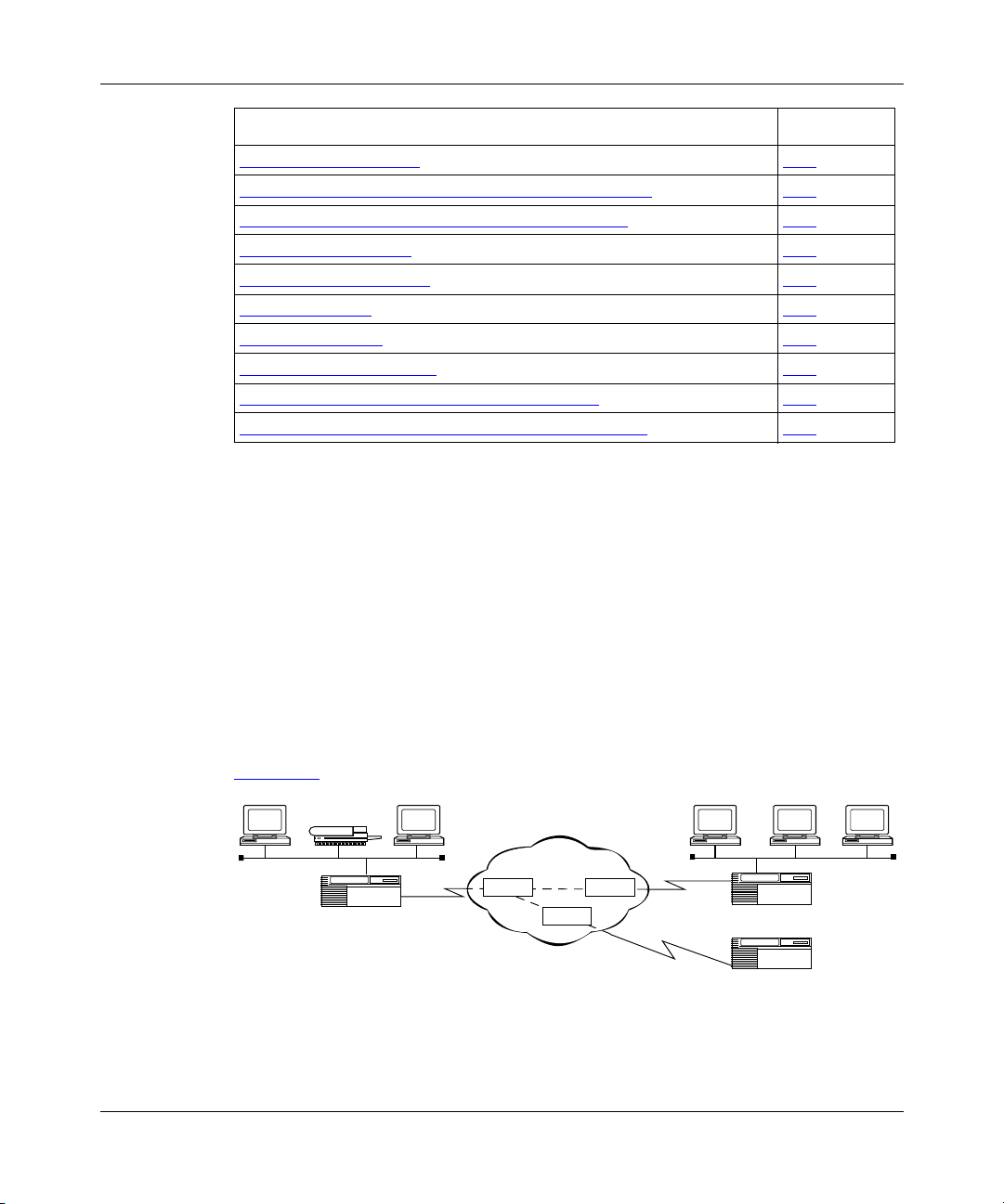
Figure 1-1
Frame relay defines the interface between
the DTE (router) and the DCE (switch)
Figure 1-1. Frame Relay Network
illustrates a frame relay network.
Frame relay
network
Switch
Router
VC
VC
Switch
Switch
VC=virtual circuit
Router
Router
FR0001A
308624-14.20 Rev 00
Page 25

Frame relay assumes that networks use transmission lines with low error rates,
such as digital transmission media. Therefore, frame relay provides only basic
error detection with no error recovery. This minimizes the processing required for
each packet, allowing frame relay networks to operate at high speeds with few
network delays.
Because frame relay performs only basic error checking, end stations running
upper-layer protocols such as the Internet Protocol (IP) are responsible for
resending packets that did not transmit correctly the first time.
Permanent Virtual Circuits
A permanent virtual circuit (PVC) is a dedicated logical path that connects two
devices over a network. When configured, a PVC is always available to the
connected devices; a PVC does not require setup before data can travel across the
network, nor does it need to be disconnected after data has passed. Because many
PVCs can coexist for one physical line, devices can share the bandwidth of the
transmission line.
Frame Relay Overview
Switched Virtual Circuits
A switched virtual circuit (SVC) is a logical path that is established on an
as-needed basis. That is, an SVC exists only when there is data to transfer. SVCs
can connect any two points on a network without the requirement that the provider
preconfigure virtual circuits (VCs).
SVCs can provide an alternative to a large network infrastructure, potentially
resulting in cost savings for networks with infrequent communications between
sites. SVCs can also provide an easy and relatively inexpensive solution for
disaster recovery. Costs associated with having a redundant PVC are eliminated.
In addition, you can prepare an SVC network for disaster recovery by performing
incremental backups to a mirror-image database on a remote server.
In addition to cost savings, SVCs provide other benefits. When frame relay
networks using global addressing approach a thousand sites, they run out of data
link connection identifiers (DLCIs). SVCs enable you to manage connectivity on
the basis of use rather than permanent connections. Using SVCs also simplifies
network administration because you do not have to preconfigure network
topologies and support moves, additions, and changes, as with PVCs. This can be
a significant benefit in large, highly meshed networks.
308624-14.20 Rev 00
1-3
Page 26

Configuring Frame Relay Services
SVCs provide true bandwidth-on-demand service that you can customize based
on the application in use. For example, a short interactive session might use an
SVC with a low or zero committed information rate (CIR) or throughput rate,
while a large file transfer of time-critical data might require an SVC at a high CIR
value.
PVC and SVC Comparison
Tabl e 1-1 lists the protocols and features that PVCs and SVCs support.
Table 1-1. PVC and SVC Protocol and Feature Support
Protocol/Feature PVCs Support SVCs Support
IP, IPX ✓✓
AppleTalk
APPN
Bridging
DECnet
LLC
OSI
VINES
XNS
Data compression (WCP) ✓✓
Data encryption (WEP) ✓
Data link switching (DLSw) ✓✓
Protocol prioritization ✓✓
Dial-on-demand ✓✓
Dial backup ✓✓
Congestion control ✓✓
Traffic shaping ✓✓
PVC pass-through ✓
Multiline ✓
✓
1-4
308624-14.20 Rev 00
Page 27
Frame Relay Packets
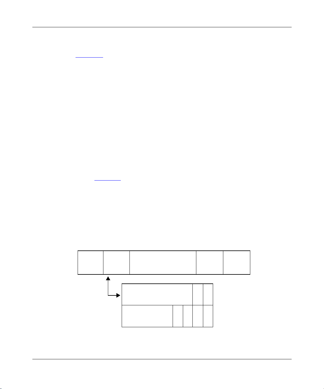
Figure 1-2 illustrates the structure of a frame relay packet. The packet’s header
field includes the following:
• Data link connection identifier (DLCI)
The DLCI is the virtual circuit identification number. The frame relay network
uses the DLCI to direct basic data flow. You configure the DLCI for PVCs.
For SVCs, the frame relay switch assigns the DLCI number on a per call
basis.
• Command/response bit (C/R)
ITU-T (formerly CCITT) standards do not use this bit.
• Forward explicit congestion notification (FECN) and backward explicit
congestion notification (BECN)
The FECN and BECN indicate congestion on the network. For information
about how the frame relay software uses these bits, see “Congestion Control,”
on page 1-22
Frame Relay Overview
.
• Discard eligibility (DE)
The DE bit allows the router to mark specific frames as low priority (discard
eligible) before transmitting them to the frame relay network.
• Extended address bit (EA)
The EA bit signals whether the next byte is part of the address. This bit
indicates the last byte of the DLCI.
Frame
Flag
relay
header
8 7 6 5 4321
DLCI (low order)
Figure 1-2. Frame Relay Header: 2-Byte Format
Information
(data)
DLCI (high order) C/R
B
F
E
E
C
N
DE
C
N
CRC
EA
EA
Flag
FR0002A
308624-14.20 Rev 00
1-5
Page 28

Configuring Frame Relay Services
Figure 1-2 shows the frame relay header as a 2-byte structure. Frame relay can
also format the header using 3 or 4 bytes, as shown in Figure 1-3
that you must configure the frame relay interface on the router to use the same
header length as the switched network to which it is connected.
3-byte format 4-byte format
. Note, however,
876 54 3 2 187654321
DLCI (high order)
DLCI
DLCI (low order)
or
DL-CORE control
C/R EA
F
B
E
E
DE EA
C
C
N
N
D/C EA
DLCI (high order) C/R
DLCI
(low order)
DLCI (low order)
DL-CORE control
F
E
C
N
DLCI EA
or
Figure 1-3. Frame Relay Header: 3- and 4-Byte Formats
B
E
C
N
EA
DE
EA
D/C EA
FR0003A
1-6
308624-14.20 Rev 00
Page 29
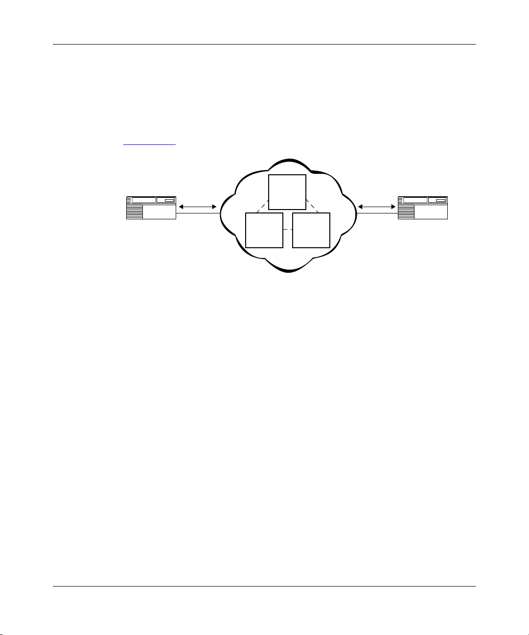
Management Protocols
Frame relay is an access protocol that runs between a router or data terminal
equipment (DTE) and a switch or data communications equipment (DCE). The
router and the switch use the Data Link Control Management Interface (DLCMI)
to exchange information about the interface and the status of each virtual circuit
(Figure 1-4)
.
DLCMI DLCMI
Frame Relay Overview
Network
node
switch
Router
Frame
relay
Network
node
switch
Network
node
switch
Frame
relay
Router
FR0004A
Figure 1-4. Structure of the DLCMI
DLCMI supports three standard data link management specifications: LMI, ANSI
T1.617 Annex D, and CCITT (now ITU-T) Q.933 Annex A.
• The networking industry first developed the Local Management Interface
(LMI) specification. The LMI approach is asymmetric; the router sends a
status-inquiry message to the network, signaling that the router’s connection
to the network is functioning. The network replies with a status response.
• ANSI modified the LMI specification and incorporated it as Annex D to
ANSI standard T1.617. The ANSI method is generally similar to the LMI
approach.
• The CCITT (now ITU-T) modified the ANSI standard and adopted it as
Annex A to Q.933. The CCITT Annex A specification is similar to Annex D,
but it uses an international numbering scheme.
Be sure to configure the frame relay interface on the router to use the same
management protocol as the switched network to which it is connected. For
information about configuring frame relay, see Chapter 3, “Customizing Frame
Relay Interfaces.”
308624-14.20 Rev 00
1-7
Page 30

Configuring Frame Relay Services
Frame Relay SVC Signaling and LAPF
Figure 1-5 shows the layers of protocol standards for frame relay signaling:
• The LAPF Core layer defines basic frame relay protocol for both PVCs and
SVCs and supports the reliable transfer of multiple numbered frames over
SVCs.
• The DLCMI layer defines link management protocol for PVCs.
• The LAPF and Q.933 layers define link management protocol for SVCs.
Q.933 or FR.4
Define link
management
protocol
for SVCs
DLCMI
LAPF
LAPF Core
Physical media
Defines link
management
protocol
for PVCs
Defines basic
frame relay
protocol common to
PVCs and SVCs
FR0018A
Figure 1-5. Frame Relay Signaling and LAPF Standards
The link access procedure, frame mode (LAPF) layer defines five unnumbered
control frames and three numbered supervisory frames on the communications
link.
1-8
308624-14.20 Rev 00
Page 31

Frame Relay Overview
LAPF defines the following categories of management frames to support reliable
transfer of multiple numbered frames over SVCs:
—
• Unnumbered control
Provides connection and disconnection services and
includes set asynchronous balanced mode extended (SABME), disconnect
(DISC), frame reject (FRMR), disconnected mode (DM), and unnumbered
acknowledgment (UA) frames.
—
• Numbered supervisory
Provides flow control and retransmission
information and includes receiver not ready (RNR), receiver ready (RR), and
reject (REJ) frames.
—
• Numbered information (I)
A numbered command/response that passes data
across the link using a sliding window protocol. The frames are numbered
sequentially and carry an acknowledgment of the highest numbered frame
received by the sending peer. The maximum number of frames outstanding is
configurable. These frames can only be sent after setup of multiple frame
communications on the link. A flag within the frame differentiates a
command from its response.
• Exchange identification (XID)
allow peers to exchange identification information.
LAPF Operational States
LAPF has three main operational states:
• TEI-assigned
base interface state. When the LAPF circuit is first established, this is its state.
No timers are running and only unnumbered frames are supported across the
link.
—
• Active
the interface. Numbered information frames can travel across the link.
• Timer recovery
attempting to recover either through retransmission (T200 timeout) or by
initiating an idle time handshake (T203 timeout).
When multiple frame support is operating on the channel, numbered information
frames are exchanged to transfer data and acknowledge earlier transfers.
This state indicates that multiple frame support is up and running on
—
An unnumbered command/response used to
—
The terminal end-point identifier (TEI)-assigned state is the
—
This state indicates that a timer has expired and the peer is
308624-14.20 Rev 00
1-9
Page 32

Configuring Frame Relay Services
LAPF Timeout and Retransmission Timers
Tabl e 1-2 lists the timers and retransmission limits defined in the LAPF protocol
for timeouts and retransmissions.
Table 1-2. LAPF Timeout and Retransmission Timers
Site Manager Parameter Description
T200 This general purpose retransmission timeout is
used during initiation of LAPF multiple frame
support and for timeout of numbered information
frames.
T203 This timeout detects excessive idle time on the
line and initiates a frame handshake to check if
the connection is still up.
N200 This maximum retransmission count, when
reached, causes the software to take action. The
action taken by the router software depends on
the type of message timed out and the state of
the service.
1-10
Timer T200
Timer T200 detects transmission timeouts. When a timeout occurs, the peer enters
the timer recovery state and retransmits the frame, up to a maximum of N200
times. If this limit is reached, the system performs the following operations:
• Terminates multiple frame operation
• Discards all outstanding information frames
• Transitions the peer to the TEI-assigned state
• Initiates multiple frame setup
If the remote peer receives a frame that contains an error, it sends an REJ message
to specify which frame was in error. In response, the local peer retransmits
information frames, beginning with the bad frame.
If the remote peer encounters an error that retransmission cannot remedy, it sends
an FRMR response to the local peer and transitions to the TEI-assigned state. The
local peer discards all outstanding information frames, transitions to the
TEI-assigned state, and initiates multiple frame setup.
308624-14.20 Rev 00
Page 33

The supervisory frames, RNR and RR, support flow control on the channel. If the
receiver is not ready to receive data, it sends an RNR message to tell the sender to
wait. When it is ready to receive data, it sends an RR message. Flow control in one
direction is independent of the other direction.
Timer T203
Timer T203 is used to detect a lost connection. When either end of the link is not
waiting for any data, it starts timer T203. If it sends or receives no frames before
this timer expires, the peer transitions to the timer recovery state, sends either an
RR or RNR message to the remote peer, and starts timer T200. If timer T200
expires, the connection is assumed lost, and the peer transitions to the
TEI-assigned state.
To terminate multiple frame support on the circuit, one peer sends a DISC
message to the other. The receiving peer responds with a UA message, and
disconnects the circuit.
SVC Signaling
Frame Relay Overview
The following sections describe the signaling between a DTE and the frame relay
network in which various types of messages are exchanged.
Tabl e 1-3
Chapter 5, “Customizing SVCs,” describes how you can use the BCC or Site
Manager to configure these timers to your specific requirements.
Call Setup
A frame relay SVC is established using the frame relay signaling protocol
between the subscriber (DTE) and the network. This protocol is described in the
sections that follow. The timers used in this process are summarized in Tabl e 1- 3
Note that the Timer column in Ta bl e 1- 3
for the timer.
308624-14.20 Rev 00
contains a list of timers used in the signaling exchanges that occur.
.
lists the Site Manager parameter name
1-11
Page 34

Configuring Frame Relay Services
Table 1-3. Network Timers
Default
Timeout
Timer
(secs) State of Call Cause for Start Normal Stop
At First
Expiration
At Second
Expiration
T303 4 Call present Outgoing setup
message
T305 30 Disconnect
indication
T308 4 Release
request
T310 10 Incoming
call
proceeding
T322 4 Any state Outgoing status
Outgoing
disconnect
message
Outgoing
release
message
Incoming call
proceeding
message
inquiry message
Incoming connect,
call proceeding, or
release message
Incoming disconnect
or release message
Incoming release or
release complete
message
Incoming connect or
disconnect message
Incoming status,
disconnect, release,
or release complete
message
Retransmit setup
message; restart
timer T303
Network sends
release message
Retransmit
release message;
restart timer T308
Call cleared Timer not
Retransmit status
inquiry message;
restart timer T322
Call cleared
Timer not
restarted
Call cleared;
timer not
restarted
restarted
Retransmit
status inquiry
message;
restart timer
T322
1-12
308624-14.20 Rev 00
Page 35

Message Processing
Tabl e 1-4 shows how the router software handles various types of message
exchanges.
Table 1-4. Message Processing
Message Type Message Processing
Call setup When the software receives a setup message, it performs several
Call proceeding After the network determines that the setup message is valid and
Connect When the called subscriber accepts a call, it sends a connect
Disconnect When a subscriber wants to terminate a call, it sends a disconnect
Frame Relay Overview
validations before it can deliver the message to the called
subscriber and return a call proceeding message to the calling
subscriber.
The software must verify that all of the information fields in the
message are in the proper order, all of the mandatory elements are
present, and that all elements contain appropriate values.
contains all the appropriate information, it returns a call proceeding
message to the calling subscriber.
When the network delivers the setup message to the called
subscriber, the called subscriber may then return a call proceeding
message to the network.
message back to the network. The network validates the message
and checks any negotiable parameters. If the message passes this
inspection, the network passes the message back to the calling
subscriber.
message to the network. The network validates the messages and
passes it to the peer subscriber.
308624-14.20 Rev 00
The cause information element is mandatory in the disconnect
message. Under normal conditions, it contains a value of 16,
“Normal Call Clearing.”
(continued)
1-13
Page 36

Configuring Frame Relay Services
Table 1-4. Message Processing
Message Type Message Processing
Release Under normal call clearing conditions, the network passes the
disconnect message through the network to the remote subscriber.
The subscriber receiving this disconnect message responds with a
release message. The network validates the release message and
passes it to the local subscriber.
Release complete Once the network receives a release message from the subscriber
and verifies it, the network returns a release complete message to
the subscriber. After receiving the release message from the
network, the subscriber responds with a release complete
message.
Frame Relay Service Records
The router software uses service records to define frame relay circuits. A service
record is a data structure that allows flexible grouping and characterization of
VCs. A service record can contain a single PVC or SVC, multiple PVCs or SVCs,
or a combination of PVCs and SVCs.
Service records:
• Simplify network addressing for VCs because you define and associate only
one protocol address with groups of frame relay VCs.
(continued)
• Allow multiple groups of VCs per frame relay interface.
• Enable you to group multiple VCs for each network protocol into separate
service records, thereby reducing the number of buffers needed per circuit
during broadcasts.
• Lower customer costs by creating multiple broadcast domains.
• Conserve resources because they require a small number of circuits.
• Are easy to configure.
Default Service Record
The router creates the first service record automatically when you select frame
relay as your WAN protocol. This first service record is the default service record.
Any VCs not associated with another configured service record use the default
service record.
1-14
308624-14.20 Rev 00
Page 37

Multiple Service Records
Interfaces can have multiple service records, and each service record can contain
multiple PVCs, SVCs, or combinations of PVCs and SVCs.
Adding and Moving PVCs
You can add PVCs to a service record either individually, or in a range. You can
also move PVCs on the same interface from one service record to another
individually or as a group. For instructions, see “Deleting Frame Relay” on
page 3-12.
Frame Relay Access Modes
Nortel Networks describes frame relay PVCs in terms of three access modes:
group, direct, and hybrid. The following topics define each of these modes within
the context of service records.
Frame Relay Overview
Group Access Mode
Group mode describes a service record with multiple VCs. It represents a true
point-to-multipoint circuit. In group access mode, upper-layer protocols treat each
frame relay network interface as a single access point to the switched network.
The upper-layer protocols use a single network address to send all traffic destined
for the switched network to the frame relay network interface.
When you configure each router, you assign only one network address (for
example, an IP or IPX address) to the frame relay interface, not to each VC. The
Data Link Control Management Interface (DLCMI) dynamically configures VCs
on the default service record; you do not need to explicitly configure them.
Service records in group mode:
• Allow multiple groups of PVCs per frame relay connection.
• Enable you to gather multiple VCs for each network protocol into a separate
group or service record, thereby reducing the number of buffers needed per
circuit during broadcasts.
• Lower customer costs by creating multiple broadcast domains.
308624-14.20 Rev 00
1-15
Page 38

Configuring Frame Relay Services
Direct Access Mode
Direct mode describes a service record with one PVC. In direct access mode,
upper-layer protocols treat the frame relay network as a series of point-to-point
connections. The upper-layer protocols view each PVC as an individual network
interface.
Service records in direct access mode:
• Limit broadcasts to one PVC.
• Enable multiple layer 3 networks per interface.
Hybrid Access Mode
Hybrid access mode, as its name implies, combines characteristics of group and
direct access modes. Frame relay hybrid mode enables you to use the same PVCs
for both routing and bridging. It works only for non-fully meshed network
configurations that use:
• Both bridging and routing over a single frame relay interface
• Spanning tree bridging
1-16
In a fully meshed network, PVCs exist between each pair of nodes in the network.
In a non-fully meshed network, PVCs exist only between nodes that need to
communicate. Figure 1-6
Bridge protocol sees two interfaces
to the network
Routing
protocol
I = Interface to network
Figure 1-6. Hybrid Mode Configuration, Non-Fully Meshed Network
I
Bridge
protocol
shows a non-fully meshed network using hybrid mode.
Frame relay
network interface
Hybrid PVC
I
I
Hybrid PVC
Routing protocol sees
one interface to the network
Direction of data
SITE A
Frame
relay
network
SITE B
FR0007A
308624-14.20 Rev 00
Page 39

Using Hybrid Mode for Transparent Bridging
Figure 1-7 shows bridged traffic between site A and site B. The bridge (router 1)
is running on the frame relay interface, and its configuration does not use hybrid
mode.
Frame Relay Overview
Bridge port sees one
path to sites A and B
C
Router 1
D
Frame
relay
network
Figure 1-7. Example of a Bridged Network
In this example, the bridge receives data from site A. If the bridge does not
recognize the destination address, it tries to direct traffic through another bridge
port. However, without hybrid access mode configured, the frame relay bridge
port views the paths to site A and site B as the same path. Because the bridge does
not send out data on the same port from which it just received data, the bridge
does not direct the data to site B. In this case, you should use hybrid access mode.
Router 2
Router 3
A
Site A
E
B
Site B
F
FR0008A
If you define the PVCs in hybrid mode (see Figure 1-6
acts as a separate bridge port. This enables the bridge running on the frame relay
interface to view the traffic from site A as arriving on a different port than that of
site B. When the bridge sends out data, it sends it out from all ports, including the
port that has access to site B. Therefore, data from site A can reach site B.
You configure hybrid mode by enabling the Hybrid Mode parameter for PVCs.
For instructions, see “Configuring Hybrid Mode for PVCs” on page 4-12.
308624-14.20 Rev 00
on page 1-16), each PVC
1-17
Page 40

Configuring Frame Relay Services
Source Routing
Source routing is the method by which a bridge sends data across two networks.
The router supports source routing over frame relay networks, using RFC 1490
standard frame relay data encapsulation.
To configure source routing, see Configuring Bridging Services.
RFC 1490
RFC 1490 defines the encapsulation method for sending data across a frame relay
network. Nortel Networks routers implement RFC 1490 for all protocols that
Nortel Networks supports over frame relay networks.
Address Resolution for PVCs
Address resolution for PVCs maps a remote network address such as an IP
address to a local DLCI number. For most protocols that you configure for a frame
relay interface, the router performs address resolution automatically. However, IP,
AppleTalk, and VINES
dynamically generates an ARP table of addresses and DLCI numbers by sending
messages back and forth to each network node to gather address information. This
process increases broadcast traffic across the network.
use the Address Resolution Protocol (ARP). ARP
1-18
To reduce broadcast traffic for all protocols, you can configure static routes and
adjacent hosts at the protocol level. This eliminates the need for the router to
perform address resolution. To reduce traffic associated specifically with VINES
address resolution, you can configure Inverse ARP. Inverse ARP is the default for
IP over frame relay. See the appropriate protocol manual for more information
about static routes, adjacent hosts, and Inverse ARP.
Tabl e 1-5
whether you can reduce broadcast traffic by modifying the address resolution
configuration.
lists how the router handles address resolution for each protocol and
308624-14.20 Rev 00
Page 41

Frame Relay Overview
Table 1-5. How Protocols Handle Address Resolution
How Router Performs
Protocol
Bridge (including
source route) Automatic None
IP ARP
DECnet IV Automatic None
VINES ARP
Internet Packet
Exchange (IPX)
Xerox Networking
System (XNS)
AppleTalk AppleTalk ARP None
Address Resolution Configuration Requirements
Configure ARP
or
Inverse ARP
or
Inverse ARP
Automatic None
Automatic None
Configure Inverse ARP
None for ARP
Inverse ARP is the default for
frame relay.
Address Resolution for SVCs
For SVCs, adjacent host configuration including either an E.164 or X.121 address
eliminates the need for the router to do address resolution.
Traffic Control
Frame relay is unreliable. It does not include error recovery mechanisms, relying
instead on the upper-layer protocols to detect and retransmit lost frames.
Hub and spoke topologies often present a “big pipe/little pipe” situation. The
central or hub site has a faster link to the frame relay service because it is a point
of concentration for many remote sites. The central or hub site has a “big pipe,”
with, for example, a T1/E1 connection that can transmit data at rates of 1.54 Mb/s.
The remote sites usually support a much lower line speed, 56 Kb/s to 64 Kb/s, or
“little pipe.” Figure 1-8
308624-14.20 Rev 00
illustrates this concept.
1-19
Page 42

Configuring Frame Relay Services
1.536/2.048Mb/s
A
Figure 1-8. Big Pipe/Little Pipe Topology
64 Kb/s
64 Kb/s
B
64 Kb/s C
D
FR0013A
The central site router sends traffic at its available bandwidth, in this example at
T1 rates (1.536 Mb/s in the United States and Canada, 2.048Mb/s elsewhere).
Some switches recognize that the remote site is configured at a lower speed, and
begin to drop frames above the capacity of the remote site router. At the remote
site, the frame relay interface discards frames beyond its available buffer. The
assumption is that the user application detects the lost frames and either
retransmits them or uses a flow control mechanism in the protocol, such as
windowing, to throttle, which means queue, the traffic. But not all applications
have a robust mechanism to deal with lost or out-of-sequence frames.
You can use Nortel Networks WAN Compression Protocol (WCP), protocol
prioritization, congestion control, and traffic shaping either singly or in
combination to help control the flow of traffic and avoid loss of data.
Data Compression
You can configure both hardware- and software-based data compression over
WANs running frame relay.
Enabling compression improves bandwidth efficiency by eliminating redundant
strings in data streams. This, in turn, improves network response times and
reduces line costs. Enabling compression on a frame relay link also provides
reliability. Both sides of a link using compression maintain a history of data that
has already traveled across the network, and WCP detects and retransmits dropped
packets.
1-20
308624-14.20 Rev 00
Page 43

To use data compression with frame relay, ensure that compression control is
enabled (the default) and select WCP as one of the protocols for the interface. For
more information about enabling compression, see “Disabling and Reenabling
Data Compression for PVCs” on page 4-26. For more information about data
compression, see Configuring Data Compression Services.
Data Encryption
Nortel Networks data encryption services enable you to protect sensitive traffic on
your network. Encryption for frame relay circuits works with direct mode PVCs
only. For information about and instructions for configuring data encryption, see
Configuring Data Encryption Services.
Protocol Prioritization
You can set priorities for the traffic sent across a synchronous line interface using
protocol prioritization, also called priority queueing. The ability to prioritize
traffic is important for an application that is time-sensitive and that requires a fast
response.
Frame Relay Overview
For example, a user at router A participating in a Telnet session with router B
requires a more immediate response than does a user at router A performing a file
transfer with router B.
When you select frame relay on a circuit, the router enables protocol prioritization
automatically. It does so because the DLCMI packets must have a higher priority
than any other packets you are sending across the network.
Enabling frame relay multiline affects protocol prioritization. For more
information, see “Protocol Prioritization and Multiline Incompatibility
page 1-39
For information about configuring protocol prioritization, see Configuring Traffic
Filters and Protocol Prioritization.
308624-14.20 Rev 00
” on
.
1-21
Page 44

Configuring Frame Relay Services
Congestion Control
Network congestion can degrade network performance. Congestion occurs when a
node receives more frames than it can process, or sends more frames than the
transmission line can handle. The frame relay network informs the nodes of
congestion, so that they can reduce the amount of traffic across the network.
In the frame relay packet header, there are two bits that the network sets to alert
nodes of network congestion. These bits, as defined by the frame relay
specification, are the forward explicit congestion notation (FECN) bit and the
backward explicit congestion notation (BECN) bit.
If the network detects congestion, it alerts the router in the same direction as the
received frame by changing the frame’s FECN bit from 0 to 1. For nodes in the
opposite direction of the received frame, it changes the frame’s BECN bit from 0
to 1 (Figure 1-9)
Congestion
direction
.
Frame relay
network
node
1-22
BECN
Frame relay
network
node
Frame relay
network
node
FECN
FR0010A
Figure 1-9. Detecting and Controlling Network Congestion
If you enable congestion control, you can specify the number of FECN/BECN bits
the router receives in a given time period before it stops transmitting frames.
While frames are going across the network, the frame relay interface checks
received packets for FECN and BECN bits set to 1. If the interface receives the
specified number of bits during the designated time period, frame relay drops all
traffic destined for the PVC where there is congestion. When the interface no
longer receives these congestion notifications, the router resumes transmission.
308624-14.20 Rev 00
Page 45

For example, suppose you set the congestion timer to 0.5 second and the
congestion count to 3. In this case, if an interface receives three FECNs or BECNs
within 0.5 second, the node stops sending frames (although it continues to receive
frames for this PVC). If the interface receives no FECNs or BECNs during the
next 0.5 second, the router resumes transmission.
If you enable congestion control and also enable traffic shaping, you can throttle,
which means queue, congested traffic rather than lose it. Throttle is one of the
options for the congestion method.
For instructions on configuring the congestion parameters, see “Controlling
Congestion for PVCs” on page 4-15 and “Controlling Congestion for SVCs” on
page 5-26.
Traffic Shaping
Traffic shaping relieves bottlenecks in topologies with high-speed connections to
the central site, and low-speed connections at remote sites (Figure 1-8
1-20
). Committed information rate enforcement and quality of service are the
major components of Nortel Networks traffic shaping.
Frame Relay Overview
on page
Committed Information Rate
The committed information rate (CIR) is the rate at which the network supports
data transfer under normal operations. Its name is descriptive: you have a contract
with your carrier, who has committed to providing a given throughput, here called
the committed information rate. The CIR is measured in bits per second. You
configure this value that the carrier provides per virtual circuit.
308624-14.20 Rev 00
1-23
Page 46

Configuring Frame Relay Services
When configuring the CIR, consider the following:
• CIR of 0
You can contract with a carrier for a CIR of 0, which yields best-effort service
at low cost. The carrier transmits data, but does not commit to providing a
specified throughput. To configure a CIR of 0, set both the throughput (which
is the CIR) and the committed burst (B
a value greater than 0. For more information about burst rates, see the next
section, “Committed Burst Rate and Excess Burst Rate
• Maximum CIR
The maximum CIR should not be greater than the speed of the access line on
the slower end of a virtual circuit. In a big pipe/little pipe topology (Figure 1-8
on page 1-20
64 Kb/s. If you configure CIRs for these virtual circuits at the central site, you
can use CIR enforcement (described in the next topic) to prevent the big pipe
from sending traffic that exceeds the PVC CIRs.
• CIR enforcement
CIR enforcement means restricting the speed of outbound traffic to a rate no
faster than the CIR. It is the major component of traffic shaping. You can
configure CIR enforcement to operate over Synchronous, High-Speed Serial
Interface (HSSI), T1, E1, and Integrated Services Digital Network (ISDN)
lines, for frame relay backup, demand, bandwidth-on-demand, and leased
lines at the virtual circuit level. CIR enforcement operates on whole frames
only. It controls congestion either by bringing down the virtual circuit, or by
throttling the traffic.
) to 0, and set the excess burst (Be) to
c
.”
), likely CIRs at the remote sites would be 32 Kb/s, 56 Kb/s, or
Committed Burst Rate and Excess Burst Rate
The committed burst rate (Bc) defines the number of bits that the router can
1-24
transmit over a specified time interval (T
excess burst (B
over the T
) defines the number of extra bits that the router attempts to send
e
when there is no congestion. Both the Bc and the Be are values that
c
you configure.
The sum of the B
across the network per T
and the Be is the maximum amount of traffic that can travel
c
when there is no congestion. If you set the Be to a value
c
greater than zero, the router can send traffic exceeding the CIR. To enforce the
CIR, that is, to limit traffic that the router can send to the amount of the CIR, set
the B
to 0.
e
) when congestion is occurring. The
c
308624-14.20 Rev 00
Page 47

If you enable congestion control and set the congestion method to throttle, the
virtual circuit sends only B
occurs, even if you have configured the B
excess data until congestion abates. If you set the congestion method to
throttle-then-shutdown, the virtual circuit first queues traffic when congestion
occurs, and then terminates the virtual circuit if throttling does not alleviate
congestion.
To configure the committed and excess burst rates, see “Using Traffic Shaping” on
page 4-21 or “Using Traffic Shaping with SVCs” on page 5-33.
Quality of Service
Quality of Service (QoS) is the second major component of Nortel Networks
traffic shaping. It uses protocol prioritization with traffic shaping. You configure a
prioritization filter on the default service record for the entire frame relay
interface, and CIR enforcement per virtual circuit (VC). QoS operates over
Synchronous, HSSI, T1, E1, and ISDN lines, for backup, demand, and for leased
lines. Although the HSSI driver does not support protocol prioritization, VCs on
an HSSI interface do.
Frame Relay Overview
bits of data over the time interval Tc when congestion
c
to a value greater than 0. It queues the
e
Using protocol prioritization with traffic shaping creates two levels of queues. For
traffic shaping the queues are high/normal/low at the VC level. For protocol
prioritization they are interrupt/shaping/high/normal/low at the driver level.
Figure 1-10
308624-14.20 Rev 00
illustrates this concept.
1-25
Page 48
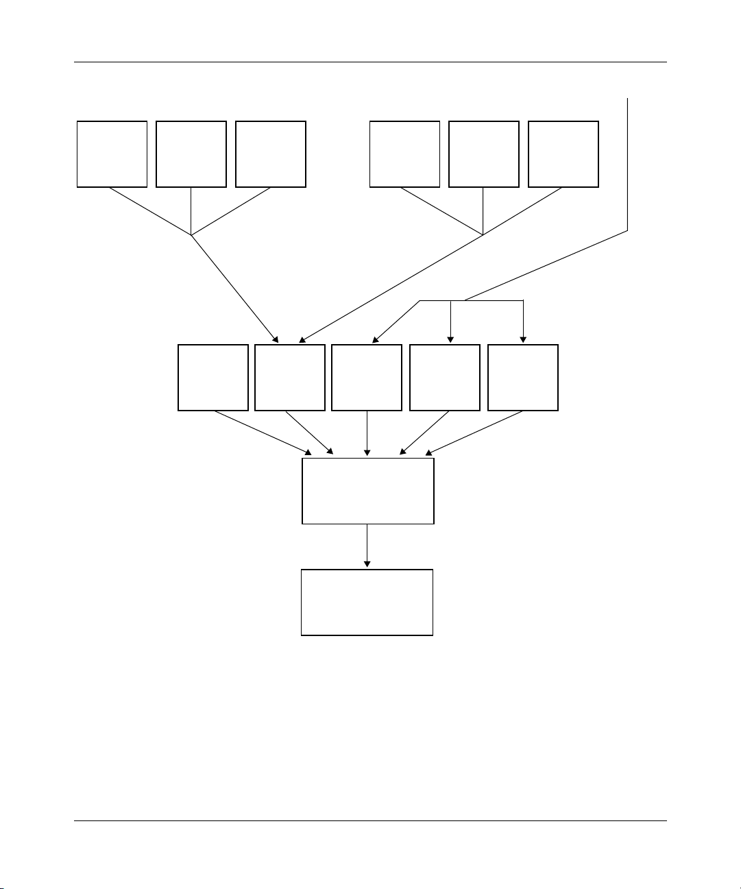
Configuring Frame Relay Services
Shaped VC1
SNA SNAIPX
High
Normal Low
LMI
(Interrupt)
Shaping
High
SNA IPXIP
High
Normal Low
Shaped VC2 Normal VCs
IPX FTPTelnet
Normal Low
Figure 1-10. Traffic Shaping Queues
1-26
Transmit queue
Attached media
FR0014A
308624-14.20 Rev 00
Page 49

Frame Relay Overview
All traffic that goes to a traffic-shaped VC (VC1 or VC2) is queued as high,
normal, or low priority at the VC level, and then it travels, by priority order, to a
shaping queue within the driver. Normal VC traffic is queued as high, normal, or
low priority at the driver level. At the driver level:
• Interrupt priority traffic, DLCMI/LMI requests (the LMI box in Figure 1-10
has the highest priority. You cannot change this.
• Shaped priority traffic (the Shaping box in Figure 1-10
highest priority.
• Normal VC traffic (not shaped) has lower priority than shaped traffic. You can
still prioritize normal VC traffic as high, normal, or low.
Queuing and prioritization only matter when the traffic rate exceeds the VC line
rate or the CIR. If the total of all traffic is below the CIR, the router just transmits
it.
You cannot prioritize between VCs on which you have enabled traffic shaping.
The router schedules traffic among them in a round-robin manner.
For information about configuring filters for protocol prioritization, see
Configuring Traffic Filters and Protocol Prioritization.
Traffic Shaping for SVCs
Traffic shaping for SVCs works according to the descriptions in the previous
sections, except that SVCs derive the committed burst, excess burst, and
throughput values from a combination of the traffic shaping parameters that you
configure and values that the frame relay network imposes. The values that the
network imposes are called link layer core (LL Core) values.
),
) has the second
Requesting Quality of Service
When you configure traffic shaping for an SVC, you have several alternatives to
achieve the quality of service that will best serve your network:
• You can enable SVC traffic shaping without providing values for the traffic
308624-14.20 Rev 00
shaping parameters. The SVCs you configure in this way use LL Core values
that the network provides.
1-27
Page 50

Configuring Frame Relay Services
• You can enable SVC traffic shaping and provide values for the LL Core traffic
shaping parameters.
If you supply values for the LL Core parameters, the router can only request
from the frame relay network an SVC with that configured quality of service.
The actual values for the burst capacity and throughput that the network
supplies may be less than requested because the local router, the network, and
the remote end negotiate the actual quality of service. To track the values an
SVC uses, use the Site Manager Statistics Manager (see Configuring and
Managing Routers with Site Manager) or use the BCC show commands for
SVCs (see Appendix C, “Monitoring Frame Relay Using the BCC show
Command”).
• You can disable SVC traffic shaping and provide values for the LL Core
committed burst, excess burst, and throughput.
If you configure traffic shaping this way, the router does not enforce the CIR it
requests from the frame relay network. There is a risk of oversubscribing the
interface, which may cause packets to be dropped.
Refining Quality of Service
1-28
You can refine quality of service requirements for SVCs. This means that you can
modify traffic shaping parameters for the incoming and outgoing data flow and
the minimum acceptable throughput. The values you set for these parameters
depend on where the SVC call originates.
If a local router originates the call, the LL core outgoing committed burst, excess
burst, and throughput values define characteristics of data the local router
transmits, while the LL core incoming values define characteristics of data the
local router receives.
If the local router receives a call, the outgoing values define characteristics of data
the local router receives, while incoming values define characteristics of data the
local router transmits.
Tabl e 1-6
shows the direction of data and whether the incoming or outgoing
parameters apply.
308624-14.20 Rev 00
Page 51

Frame Relay Overview
Table 1-6. Incoming and Outgoing
Call Originator Direction of Data Parameters That Apply
Local router Outgoing to remote router Outgoing
Incoming from remote router Incoming
Remote router Incoming to local router Outgoing
Outgoing from local router Incoming
For throughput, an SVC may process less throughput than it requests because the
local router, the frame relay network, and the remote end of the connection
negotiate quality of service. You can use the LL core minimum outgoing and
minimum incoming throughput values to set the lowest throughput value the
router will accept. If either the local router, the network, or the remote end cannot
guarantee that value, the SVC will not be established.
To customize incoming and outgoing data flow and throughput, see “Customizing
Traffic Shaping Quality of Service” on page 5-35.
Traffic Shaping Configuration Notes for PVCs and SVCs
Traffic shaping is best used at central offices to prevent the “big pipe” from
sending too much data too quickly to remote sites with “little pipes.” This concept
should guide your decisions about how to configure traffic shaping.
CIR Configuration Guidelines
Consider the following when you configure traffic shaping:
• In general, the value you assign to the B
excessive queuing and dropped packets.
If, however, you are sending frames that exceed the size of the B
slowly because the router must use multiple time periods to accommodate the
packet size and avoid exceeding the CIR. If setting the B
yields a value lower than packet size, set the B
For example, a typical TFTP frame is 548 bytes. If the CIR is 16,000 bits, the
configured according to the 1/4 guideline would be 4,000 bits, or 500
B
c
bytes, which is not big enough to accommodate a TFTP frame.
should equal 1/4 of the CIR to avoid
c
to 1/3 or even 1/2 of the CIR.
c
, data travels
c
to 1/4 of the CIR
c
308624-14.20 Rev 00
1-29
Page 52

Configuring Frame Relay Services
If you set the Bc to 16,000/2, or 1/2 CIR, the result is 8,000 bits, or a packet
size of 1,000 bytes, which works, but may result in excessive queuing because
the T
is 1/2 second. If you set the Bc to 16,000/3, or 1/3 CIR, the result is a Bc
c
of 5,333 bits or 666 bytes, much closer to the 548 TFTP frame size.
• If you cannot predict the typical frame size, monitor frame relay shaping
statistics for numbers of large frames and dropped frames. If either of these
numbers is increasing constantly or dramatically, adjust the B
value in small increments.
Using Data Compression and Traffic Shaping
Consider the following when you are configuring data compression and traffic
shaping for your network:
• Data compression maximizes throughput and increases reliability.
You can use compression effectively in the case of the 64 KB site that does not
use traffic shaping. You can also compensate for the throughput cost
associated with using compression and traffic shaping at the central site by
taking into account characteristics of compression and traffic shaping, and
fine-tuning traffic shaping parameters.
to a higher
c
1-30
— When you configure traffic shaping, consider the compression ratio you
want to achieve.
— If you set the B
equal to the Bc, the router doubles the amount of traffic it
e
attempts to send and, when you enable compression, compresses that
amount of traffic, because WCP compresses data at the rate it receives it.
— If you also choose throttle as the congestion method, the router will queue
traffic if congestion occurs, and thus prevent exceeding the CIR.
— Congestion may occur if compression histories are not in sync, and WCP
has to resend packets. If WCP retransmits many packets, it may exceed
the CIR.
• Traffic shaping increases reliability, controls congestion, and prioritizes
traffic.
308624-14.20 Rev 00
Page 53

Frame Relay Overview
You can use traffic shaping at one or both ends of a link, but you must use
compression at both ends of a link. It makes sense to use traffic shaping at a
central site, where you have a T1 line that sends data to remote sites with
64 KB line rates, and the goal is to control the flow of traffic and avoid
flooding the remote sites. However, if the CIR is equal to the line rate, which
could well be the case at the remote site with 64 KB line rates, there is no need
to use traffic shaping.
• Compression and traffic shaping together maximize reliability, but at the
expense of throughput.
Traffic shaping occurs at the VC level; compression, at the driver level.
Shaping therefore occurs before compression, which compromises effective
compression because only the precompressed traffic is shaped: the
compressed traffic is not shaped. WCP compresses data at the rate it receives
it, which with traffic shaping is the CIR. It is therefore unrealistic to expect a
high compression throughput for data that originates from a site that also uses
traffic shaping.
Oversubscribing the Traffic Shaping Interface
The CIRs that you configure are based on an average peak rate for the VCs on the
network. If all VCs with traffic shaping try to send data simultaneously, they may
exceed the capacity of the interface. If you oversubscribe the interface, traffic
shaping will still enforce the CIR, but there may be additional latency for reserved
flows. VCs without traffic shaping will send data after traffic-shaped VCs.
Queue Limits and Data Clipping
Nortel Networks routers maintain buffers for each traffic shaped VC. Each buffer
can hold one frame that the router cannot send because of congestion. The router
divides the number of buffers on the interface. Some facts specific to buffers are:
• The default number of buffers is 200 per interface. To change the buffer
• The software divides the number of buffers on the interface by the number of
• If you enable protocol prioritization, the default number of buffers is 30 for
308624-14.20 Rev 00
number, you can use the Technician Interface.
traffic-shaped VCs, giving each VC the same number of buffers. Therefore, if
you have ten traffic-shaped VCs per interface, each VC has 20 buffers.
high priority traffic, 200 for normal, and 30 for low.
1-31
Page 54

Configuring Frame Relay Services
You can use the Technician Interface to increase the total number of buffers for the
interface. You can also redistribute buffers among the VCs and the priority queues.
The parameters that you customize at the interface level are:
• wfFrDlcmiShapingHiQueueLimit
• wfFrDlcmiShapingNormalQueueLimit
• wfFrDlcmiShapingLoQueueLimit
The parameters you can customize at the VC level are:
• wfFrCircuitShapedHiQueueLimit.
• wfFrCircuitShapedNormalQueueLimit
• wfFrCircuitShapedLoQueueLimit
For information on using the Technician Interface, see Using Technician Interface
Software.
Congestion Counters and Timers
The router determines congestion based on a specified number of FECN and
BECN bits received during a set time period (for more information, see
“Congestion Control
VC, the router either drops traffic, throttles it, or throttles and then drops traffic,
depending on the configured congestion method.
” on page 1-22). When congestion occurs on a traffic-shaped
1-32
The FECN and BECN notifications are part of the header in a frame relay data
packet. In a big pipe/little pipe topology, the central site router A typically sends
much more data than it receives (Figure 1-11)
. This means that the remote site
routers B, C, and D that receive a lot of traffic may be getting large numbers of
FECNs, while the central site router is getting relatively few data packets, and
therefore few BECNs, and is unaware that congestion is occurring.
308624-14.20 Rev 00
Page 55

Frame Relay Overview
Flow of most traffic
Central site A
BECNs (few)
FECNs
FECNs
(many)
FECNs
Remote site B
Remote site C
Remote site D
FR0015A
Figure 1-11. FECNs and BECNs in Big Pipe/Little Pipe Topology
You may need to modify the congestion counter and the congestion timer, from
the default values of 20 FECN or BECN counts per second to, for example, 10
counts per 5 seconds to account for the differences in traffic volume to and from
the central site.
Automatic Traffic Shaping—Single Point Provisioning
Single point provisioning (SPP) is an automatic method of configuring traffic
shaping. Nortel Networks frame relay switches provide traffic shaping
configuration parameters to Nortel Networks routers using standards-based
signaling extensions to the Local Management Interface (LMI) full status
response message.
Single point provisioning simplifies end-point router DTE provisioning. SPP
informs the DTEs of the traffic contracts for a given PVC through standards-based
signaling extensions to the Link Management Protocol. This simplified
configuration of PVC provisioning reduces operational costs for managed
network services and large private WAN infrastructures. It also prevents circuit
downtime caused by misconfiguration at either end of a PVC.
308624-14.20 Rev 00
1-33
Page 56

Configuring Frame Relay Services
How BayRS Uses Single Point Provisioning
The Vendor Forum Local Management Interface (LMI) specification provides for
CIR signaling in an extension. BayRS follows this precedent by adding CIR,
committed burst (B
the following LMIs:
• T1.617 Annex D, Local Management
• ITU-T (CCITT) Q.933, Layer 3 Signaling Specification for ISDN Frame
Relaying Bearer Services
• Vendor Consortium Local Management Interface R1.0
), and excess burst (Be) parameter signaling in extensions to
c
At this time, Nortel Networks is the only vendor to provide “B
” and “Be”
c
parameter signaling over any LMI.
The signaling extensions for these parameters are standard Q.933 information
elements. The DTE ignores any additional information elements it receives. Upon
receipt of the signaled parameters, the router overrides the default parameters for
any given PVC, including those preconfigured through the router management
system.
For backward compatibility, these functions are disabled by default. You must
enable single point provisioning to realize its benefits.
Table 1-7 gives guidelines on the maximum number of PVCs you can use with the
Frame Relay SSP feature.
Table 1-7. Guidelines on the Maximum Number of PVCs*†
Maximum Number
Maximum Frame
Size for PVC
Signaling
Msg. Overhead
Cost per PVC
10018228
50098131544
1024202273292
1600 318 42 51 144
of PVCs without
Connection
Parameters
10 10 10 10
5 373111
Maximum Number
of PVCs with Both
Connection
Parameters
Maximum Number
of PVCs with LLCP
Parameters Only
Maximum Number
of PVCs with
PSCP Parameters
Only
(continued)
1-34
308624-14.20 Rev 00
Page 57

Frame Relay Overview
Table 1-7. Guidelines on the Maximum Number of PVCs*†
Maximum Number
Maximum Frame
Size for PVC
Signaling
2048 407 55 65 185
3072 612 82 98 278
4096 817 110 131 317
8192 976 221 263 743
* Source: Adapted from Table B-2 of “The Frame Relay Forum PC User-to-Network Interface (UNI) Implementation
Agreement.”
† The general formula is:
MaxNumber of PVCs = MIN((maxDLCI-minDLCI+1),TRUNC((MaxFrameSize-MsgOverhead)/(CostPerPVC)))
of PVCs without
Connection
Parameters
Note:
976 is the maximum number of PVCs allowed using a 2 octet DLCI.
Maximum Number
of PVCs with Both
Connection
Parameters
Maximum Number
of PVCs with LLCP
Parameters Only
(continued)
Maximum Number
of PVCs with
PSCP Parameters
Only
X.213 Priority for SVCs
Some frame relay networks that support SVCs can prioritize SVC data and
connection characters by setting X.213 priority parameters. You configure values
for these parameters at the router, and the frame relay network then uses them. For
instructions on configuring X.213 parameters, see “Setting X.213 Priorities for
SVCs” on page 5-41.
Inactivity Timing for SVCs
The inactivity timer and inactivity timer mode features combine to automatically
disconnect an SVC according to values that you configure for amount of time and
the direction that data is flowing over the SVC. You can configure these
parameters to apply to all SVCs in a service record, and you can also configure
them for individual SVCs.
308624-14.20 Rev 00
1-35
Page 58

Configuring Frame Relay Services
When the router establishes an SVC, the inactivity timer initializes two timers
internal to the router: one that monitors data the router transmits, and one that
monitors data the router receives. The inactivity timer mode defines how the
timers restart.
Tabl e 1-8
shows the various ways you can set these parameters, and the effect
each combination has on disconnecting SVCs.
Table 1-8. Inactivity Timer and Inactivity Timer Mode Interaction
Inactivity Timer Mode Inactivity Timers Used Disconnect SVC
Both Directions (Site Manager)
Both (BCC)
Either Direction (Site Manager)
Either (BCC)
Transmit Only (Site Manager)
Outbound (BCC)
Receive Only (Site Manager)
Inbound (BCC)
Transmit and Receive When both timers expire (no data
transmitted,
timer interval).
Transmit and Receive When either timer expires (no data
transmitted
timer interval).
Transmit When the transmit timer expires (no data
transmitted during the timer interval).
Receive When the receive timer expires (no data
received during the timer interval).
and
no data received during the
or
no data received during the
For instructions on setting these values for the inactivity parameters, see “Setting
Inactivity Values for SVCs” on page 5-22.
Note that a protocol priority filter configured with a no-reset action affects the
operation of the inactivity timer. Normally the inactivity timer resets when the
inactivity mode is set to Both or Both Directions, Either or Either Direction, or
Transmit Only or Outbound. However, if the data transmitted over an SVC
matches a protocol priority filter with a no-reset action, the inactivity timer will
not reset. Instead, the SVC may disconnect even though data is transmitting.
Managing Routing Information Protocol (RIP) and Inactivity Timing
RIP is a mechanism that IP and IPX use to inform network devices of routing
topology changes. IP and IPX let you control the frequency and destination of RIP
packets. Because RIP packets can affect how the router establishes and
disconnects frame relay SVCs, the software controls how RIP interacts with the
frame relay SVC inactivity timer and the inactivity timer mode. For more
information, see Appendix B, “RIP Management for Frame Relay SVCs.”
1-36
308624-14.20 Rev 00
Page 59

Multiline for PVCs
Frame relay provides a link redundancy feature called multiline, which works
with frame relay PVCs. Multiline is a Nortel Networks proprietary
implementation that lets you group two or more physical lines that back each
other up in case of a failure. This ensures that information arrives at its destination
on the network. In addition, if both lines are up, the router uses both lines
simultaneously. Two or more physical lines must be available for a multiline
configuration. Figure 1-12
Frame Relay Overview
illustrates a multiline configuration.
DLCI 200
Router
DLCI 200
FR0009A
Router
DLCI 100
DLCI 100
Line A
Line B
Frame
relay
network
Figure 1-12. Multiline Network
In this example, when the router receives traffic destined for the network, it
alternates or randomizes (depending on how you configure it) between line A and
line B to transmit the data. The router uses both lines simultaneously to balance
the traffic between each path. If one of these lines goes down, the router uses the
remaining line.
You can create a multiline configuration of up to four service records. Each
service record must be on a different physical line on the router. Each line should
be on a different slot to provide fault tolerance.
You must also match DLCIs in each service record of the multiline. Matching
DLCIs ensures that a backup exists for each PVC.
308624-14.20 Rev 00
1-37
Page 60

Configuring Frame Relay Services
The most important part of configuring multiline is setting the PVC DLCI
number. This number identifies each PVC, thereby specifying a path for the router
to direct data to the network. For each frame relay PVC that you configure, check
that PVCs with the same destination have the same DLCI number.
If you use multiline, packets traveling on the two paths may arrive at
Note:
their destination out of sequence. Some protocols do not tolerate packets
arriving out of sequence and, as a result, you may experience poor
performance or failures.
For more instruction on configuring multiline mode, see “Grouping Service
Records for Multiline Mode” on page 4-27.
Traffic Distribution Between Data Paths
To distribute traffic between multiline data paths, you can use one of two methods:
• Random distribution
• Address-based distribution
1-38
Random Distribution
Random distribution means that as the router sends out each packet, it alternates
between the lines. This option determines which line the packet uses based on a
randomly assigned number. For each outbound packet, the router generates a
random number that designates the line to use.
Random distribution balances traffic across lines and lets the router use the two
lines efficiently. Because packets travel on different paths, they arrive at the
destination out of sequence, and the upper-layer protocols, for example, IP and
Open Systems Interconnection (OSI), have to resequence the information. Some
protocols cannot tolerate packets arriving out of sequence, so be sure this option is
appropriate for your application.
308624-14.20 Rev 00
Page 61

Address-Based Distribution
Address-based distribution determines the data path for outbound traffic from the
source and destination address in each packet. Any given address pair always uses
the same path.
The router determines whether to route or bridge the packet, and then uses the
corresponding level of address. It uses routing-level addresses for routing traffic,
and the MAC-level addresses for bridging traffic.
Address-based distribution ensures that all outbound traffic travels on the same
path, and that packets arrive in sequence. For protocols that cannot receive packets
out of sequence, use this method. Note, however, that this option does not always
distribute traffic evenly across each line.
Protocol Prioritization and Multiline Incompatibility
You cannot use protocol prioritization with multiline. Protocol prioritization may
change the order of frames arriving over a multiline interface, and frame relay
multiline does not have the ability to correct the sequence.
Frame Relay Overview
PVC Pass-Through
The PVC pass-through service allows a single frame relay network access link to
carry both conventional network protocol traffic and otherwise unroutable frame
relay access device (FRAD) traffic. This service works with hybrid mode PVCs
only. PVC pass-through connects two PVCs on separate interfaces so that the
router can transmit traffic it receives on one PVC out the other with no
encapsulation requirements. Figure 1-13
308624-14.20 Rev 00
illustrates how PVC pass-through works.
1-39
Page 62

Configuring Frame Relay Services
DCEs
DTE
FRAD
DCE
Figure 1-13. PVC Pass-Through
Figure 1-13 shows a router with an Ethernet interface and two frame relay
interfaces. The interface to the frame relay network (on the right) is a DTE. The
interface to the FRAD (on the left) is a DCE. The router delivers all IP frames
inbound on DLCI 50 to the IP interface. It also delivers all IP frames inbound on
DLCI 30 to the IP interface. The router delivers all other traffic inbound on DLCI
30 via the PVC pass-through system to DLCI 20, which forwards the data to the
FRAD. The router delivers all data inbound on DLCI 20 via the PVC pass-through
system to DLCI 30, which forwards the data to the frame relay network.
PVC pass-through works with both leased line and dial-on-demand interfaces. It
works with Nortel Networks data compression, congestion control, and traffic
shaping. It does not work with data encryption, which requires a direct mode
PVC.
Router
DLCI 20
IP
IP router
PVC pass-through
IP
DLCI 30
DLCI 30
DLCI 50
DTE
Frame
relay
network
FR0016A
Frame Relay Dial Services
Frame relay works with Nortel Networks dial-on-demand and dial backup
services. For more information about dial services, see Configuring Dial Services.
1-40
308624-14.20 Rev 00
Page 63

Frame Relay Overview
Synchronous Line Configuration for Frame Relay
If you enable frame relay on a circuit, Site Manager automatically sets the
following synchronous line parameters (Table 1-9)
Table 1-9. Synchronous Line Parameters for Frame Relay
Parameter Value
BofL Disable
Promiscuous Enable
Service Transparent
WAN Protocol Frame Relay
:
For more information about these parameters, see Configuring WAN Line
Services.
Calculating the MTU Size for Frame Relay Connections
The maximum transmission unit (MTU) value is the largest packet size the router
will transmit across a connection. The MTU is configured as part of the WAN line
parameters and its default value for frame relay is 1600.
If your Nortel Networks router communicates across a frame relay line, you may
need to adjust the MTU value because as you add headers to the frame relay
packet, such as those for compression and encryption, the router reduces the space
for layer 3 data, such as IP or IPX datagrams.
308624-14.20 Rev 00
1-41
Page 64

Configuring Frame Relay Services
Tabl e 1-1 0 summarizes the changes you may need to make to the MTU value for
your frame relay configuration. In addition to these adjustments, other router
subsystems using frame relay, such as IP or IPX, may also affect the MTU value.
Those adjustments are based on the particular subsystem configuration.
Table 1-10. MTU Adjustments for Frame Relay Connections
Size of
Reason for the
Adjustment
Overhead
Packets (bytes)
Lines for Which the
Adjustment Applies Notes
Data compression
(WCP) overhead
Data encryption
(WEP) overhead
Cyclic redundancy
check (CRC)
3 Synchronous, MCT1,
MCE1, ISDN BRI
56 Synchronous, MCT1,
MCE1, ISDN BRI
2 or 4 Synchronous, MCT1,
MCE1, ISDN BRI
Based on the values in Tab le 1- 10
, if you configure IP over frame relay on a
The router always subtracts the WCP
header regardless of whether WCP is
enabled. Consequently, the amount of data
that the router sends across the frame relay
line will be less than you configured for the
MTU value.
The router always subtracts the WEP
header regardless of whether WCP is
enabled. Consequently, the amount of data
that the router sends across the frame relay
line will be less than you configured for the
MTU value.
The router always subtracts the CRC size.
Consequently, the amount of data that the
router sends across the frame relay line will
be less than you configured for the MTU
value. The default CRC value is 2.
synchronous line, the largest IP datagram that the router transmits is 1539. This
number is determined by taking the default MTU value (1600) and subtracting the
overhead packet sizes for WCP (3), WEP (56), and the CRC (2). To ensure that the
router sends an IP datagram size of 1600 bytes, you must set the MTU value to
1661. For more information about the MTU parameter, see Configuring WAN Line
Services.
1-42
308624-14.20 Rev 00
Page 65

Chapter 2
Starting Frame Relay
The quickest way to begin using frame relay on your network is to enable it with
default values for all interface parameters and with a default service record that
includes at least one permanent virtual circuit (PVC) or switched virtual circuit
(SVC).
This chapter includes the following topics:
Topic Page
Starting Configuration Tools
Preparing a Configuration File 2-2
Starting Frame Relay 2-2
Configuring PVCs and SVCs 2-4
Starting Configuration Tools
Before configuring frame relay services, see the appropriate user guide for
instructions on how to use the Nortel Networks configuration tool of your choice.
Configuration Tool User Guide
Bay Command Console (BCC)
Site Manager
These guides also describe generally how to create and modify a configuration.
308624-14.20 Rev 00
2-1
Using the Bay Command Console (BCC)
Configuring and Managing Routers with Site Manager
2-1
Page 66

Configuring Frame Relay Services
Preparing a Configuration File
To prepare a configuration file:
1. Create and save a configuration file that has at least one WAN interface.
Open the configuration file in local, remote, or dynamic mode.
2.
For information on these procedures, see Quick-Starting Routers.
Starting Frame Relay
You can use either the BCC or Site Manager to start frame relay using default
values for all parameters. Frame relay automatically learns the necessary PVC
information from the frame relay switch, and places the PVCs into the default
service.
Using the BCC
To enable frame relay:
1. Configure a physical interface on an available slot/connector.
2-2
To configure a physical interface on a slot and connector, navigate to the
top-level box prompt and enter:
<interface_type>
<connector_number>
interface_type
slot_number
module_number
connector_number
is the name of a link or net module on the router.
is the number of the slot on which the link module is located.
<slot_number>
slot
module
<module_number>
connector
is the number of the module on which the slot is located.
is the number of a connector on the link module.
After you configure a physical interface, the BCC returns a prompt that
specifies your current working location. For example, the following command
configures a serial interface on slot 1, connector 2.
box#
serial slot 1 connector 2
serial/1/2#
308624-14.20 Rev 00
Page 67

Starting Frame Relay
2.
Configure frame relay on the physical interface.
To configure a frame relay interface on a physical interface, navigate to the
prompt for the physical interface (for example,
frame-relay
box; serial 1/2
) and enter:
For example:
Using Site Manager
To enable frame relay, complete the following tasks:
You do this System responds
1. In the Configuration Manager window,
choose a link or net module with WAN
interfaces, and click on one of the WAN
ports, for example a COM port.
2. Choose Frame Relay and click on OK. The Select Protocols window opens.
3. Select the LAN protocols that you want to
operate on the frame relay circuit, then
click on OK.
serial1/2#
frame-relay/1/2#
frame-relay
You have enabled frame relay. You can now configure PVCs and SVCs as
described in “
Configuring PVCs and SVCs” on page 2-4. You can also
specify the protocols that you want to run on this interface.
Site Manager Procedure
The WAN Protocols window opens.
Site Manager might prompt you for
protocol configuration information. For
instructions, see the appropriate
onfiguration guides for those protocols
c
that you want to run on this interface.
You have enabled frame relay. You can now configure PVCs and SVCs as
described in “
Protocol prioritization is enabled automatically when you enable frame relay. For
information about protocol prioritization, see Configuring Traffic Filters and
Protocol Prioritization.
308624-14.20 Rev 00
Configuring PVCs and SVCs” on page 2-4.
2-3
Page 68

Configuring Frame Relay Services
Configuring PVCs and SVCs
You configure permanent virtual circuits (PVCs) and switched virtual circuits
(SVCs) after you enable frame relay.
Configuring a PVC
You can configure PVCs using either the default service record or by adding a
service record. Use these instructions to configure PVCs on the default service
record. To configure PVCs on service records that you add, see “Adding PVCs to
Service Records” on page 4-5.
Using the BCC
To add a PVC to the default service record, complete the following tasks:
1. Navigate to the frame-relay prompt.
For example:
box#
serial/3/1; frame-relay/1/2
Navigate to the default-service prompt.
2.
2-4
The BCC context changes to the default service record. For example:
frame-relay/1/2#
default-service/1/2#
3. Enter the
pvc dlci
default-service
<value>
command.
The service provider supplies the data link connection identifier (DLCI),
which uniquely identifies this PVC.
For example:
default-service/1/2#
pvc/1/2/16#
pvc dlci 16
You have added a PVC to the default service record. Repeat this procedure to add
more PVCs according to your network requirements.
308624-14.20 Rev 00
Page 69

Using Site Manager
To configure a PVC:
You do this System responds
Starting Frame Relay
Site Manager Procedure
1. In the Configuration Manager window,
choose Protocols.
2. Choose
3. Choose Services. The Frame Relay Service List window
4. Choose PVCs. The FR PVC List for Service window
5. Choose Add. The Frame Relay PVC Add window
6. Set the DLCI Number parameter. Click on
Help or see the parameter description on
page A-24.
7. Click on Done. You return to the FR PVC List for Service
8. Add more PVCs as your network requires.
9. Click on Done until you return to the
Configuration Manager window.
Frame Relay. The Frame Relay menu opens.
The Protocols menu opens.
opens.
opens.
opens.
window.
308624-14.20 Rev 00
2-5
Page 70

Configuring Frame Relay Services
Configuring an SVC
You can configure SVCs using either the default service record or by adding a
service record. Use these instructions to configure SVCs on the default service
record. To configure SVCs on service records that you add, see “Adding SVC
Options to Service Records” on page 5-7.
Using the BCC
To add an SVC to the default service record, complete the following tasks:
1. Navigate to the frame-relay prompt.
For example:
box#
serial/3/1; frame-relay/1/2
Navigate to the default-service prompt.
2.
The BCC context changes to the default service record. For example:
frame-relay/1/2#
default-service/1/2#
3. Create an SVC by enabling SVC control.
default-service
For example:
default-service/1/2#
Specify the SVC local address.
4.
svc-control enable
For example:
default-service/1/2#
address
can be any valid X.121 or E.164 address.
svc-local-address
address
<
>
For example:
svc-local-address e164, 1234567, 1234567, International
svc-local-address x121, 1234567, 1234567, International
You have now added an SVC to the default service record. Repeat this procedure
to add more SVCs according your network requirements.
2-6
308624-14.20 Rev 00
Page 71

Using Site Manager
To configure an SVC, complete the following tasks:
You do this System responds
Starting Frame Relay
Site Manager Procedure
1. In the Configuration Manager window,
choose Protocols.
2. Choose
3. Choose Services. The Frame Relay Service List window
4. Set the SVC Support parameter to
Enable.
5. Set the following parameters:
• SVC Local Party Number
• SVC Local Party Sub-Address
• SVC Local Party Number Plan
• SVC Local Party Type of Number
Click on Help or see the parameter
descriptions beginning on page A-36.
6. Click on Apply. Site Manager replaces the Multiline
7. Click on Done. You return to the Configuration Manager
Frame Relay. The Frame Relay menu opens.
(optional)
The Protocols menu opens.
opens.
The SVC parameters become available.
button with the SVCs button in the Frame
Relay Service List window.
window.
Configuring Adjacent Hosts for an SVC Service Record
If you are configuring IP or IPX for a frame relay SVC, there are special
considerations for configuring adjacent hosts. An adjacent host is a device on a
locally attached network; it may or may not be a router. For frame relay to operate
properly, the router must be able to resolve adjacent host addresses. For each
adjacent host that does not implement the address resolution protocol (ARP), you
need to configure a MAC address, or you must preempt the ARP process.
For more information about IP or IPX, see Configuring IP, ARP, RARP, RIP, and
OSPF Services or Configuring IPX Services for instructions on configuring
adjacent hosts.
308624-14.20 Rev 00
2-7
Page 72

Page 73

Chapter 3
Customizing Frame Relay Interfaces
When you enable frame relay, default values are in effect for all parameters.
Depending on your network requirements, you may want to change these values.
The following sections describe how to customize frame relay for your network.
Topic Page
Configuring Interfaces Using the BCC or Site Manager
Selecting a Management Type 3-2
Setting XOFF Control 3-4
Selecting Address Type and Length 3-5
Monitoring the Connection 3-7
Deleting Frame Relay 3-12
3-1
Configuring Interfaces Using the BCC or Site Manager
Tabl e 3-1 lists the frame relay configuration tasks described in this chapter and
indicates whether you can use the BCC or Site Manager to perform each task.
Table 3-1. Interface Configuration Tasks
Task BCC Site Manager
Selecting a Management Type
Setting XOFF Control
Selecting Address Type and Length
Monitoring the Connection
Deleting Frame Relay
✓✓
✓
✓✓
✓✓
✓
308624-14.20 Rev 00
3-1
Page 74

Configuring Frame Relay Services
Selecting a Management Type
You can specify the management protocol that the router and the frame relay
network use to communicate status information. Routers connected back to back
also use a management protocol to exchange status information. The following list
describes your options:
• DLCMI None provides no management interface between the router and the
frame relay network. In the absence of management support, you must
configure all PVCs manually.
• Rev 1 LMI provides user-side management services as specified by Revision 1
of the Local Management Interface standard.
• ANSI T1.617D provides user-side management services as specified in
Annex-D to ANSI standard T1.617-1991. This is the default value.
• CCITT Annex A provides user-side management services as specified by the
ITU-T (formerly CCITT).
• LMI Switch offers limited management services for the DCE side of the
connection as specified by Revision 1 of the Local Management Interface
standard.
3-2
• Annex D Switch provides limited management services for the DCE side of
the connection as specified in Annex D to ANSI standard T1.617-1991.
• Annex A Switch provides limited management services for the DCE side of the
connection as specified by the ITU-T.
If you are connecting two routers back to back, use one of the DTE parameter
options (Rev 1 LMI, ANSI T1.617D, or ITU Annex A) for the router acting as a
DTE, and one of the DCE options (LMI Switch, Annex D Switch, or Annex A
Switch) for the router acting as the DCE. Although you can configure the router
for the DCE side of a connection, the router cannot act as a full switch, and it will
not perform complete bidirectional signaling.
The LMI Switch, Annex D Switch, and Annex A Switch options are primarily for
troubleshooting.
You can use either the BCC or Site Manager to select a management type.
308624-14.20 Rev 00
Page 75

Using the BCC
Customizing Frame Relay Interfaces
To specify a management protocol, navigate to the dlcmi prompt (for example,
box; serial/1/2; frame-relay/1/2; dlcmi
) and enter:
management-type
value
none
lmi
annex-d
annex-a
lmi-switch
annex-d-switch
annex-a-switch
For example, the following command line changes the management type from
Annex D Switch to LMI Switch:
dlcmi/1/2#
dlcmi/1/2#
Using Site Manager
To specify a management protocol, complete the following tasks:
You do this System responds
<value>
can be:
(the default)
management-type lmi-switch
Site Manager Procedure
1. In the Configuration Manager window,
2. Click on Edit Circuit. The Frame Relay Circuit Definition
3. Click on Interfaces. The Frame Relay Interface List window
4. Set the Mgmnt Type parameter. Click on
5. Click on Apply.
308624-14.20 Rev 00
The Edit Connector window opens.
click on a port configured for frame relay.
window opens.
opens.
Help or the see the parameter description
on page A-5.
(continued)
3-3
Page 76

Configuring Frame Relay Services
You do this System responds
6. Click on Done. You return to the Frame Relay Circuit
7. Click on Done. You return to the Configuration Manager
Setting XOFF Control
If you choose LMI as the management protocol, you can use the BCC to configure
the XOFF control. The XOFF control determines whether the router ignores or
observes the XOFF bit. XOFF control is enabled by default. If you want to modify
the behavior of the XOFF bit, you can disable XOFF control.
To set the XOFF control, navigate to the dlcmi prompt (for example,
1/2; frame-relay/1/2; dlcmi
xoff-control
value
can be:
enabled
disabled
<value>
for the router to observe the XOFF bit
for the router to ignore the XOFF bit
Site Manager Procedure
Definition window.
window.
) and enter:
(continued)
box; serial/
3-4
For example, the following command line disables XOFF control:
dlcmi/1/2#
dlcmi/1/2#
xoff-control disabled
308624-14.20 Rev 00
Page 77

Selecting Address Type and Length
You can specify the data link connection identifier (DLCI) address type and length
that the router and the frame relay network use to direct packets to their
destinations. The address type for the router and for the switch must be the same.
Selecting a DLCI Address Type
The options for the DLCI address type are:
• ADDR Q922 selects addressing as specified in the final version of the Q.922
standard. Q.922 provides for FECN, BECN, DE, and EA bits. While most
Q.922 addresses are included within a 2-octet field, the standard allows for
3- and 4-octet address fields. This is the default.
• The November draft of ADDR Q922 differs from ADDR Q922 in dropping
the D/C bit from the extended (3- and 4-byte) forms. The D/C bit (DLCI or
DL-Core Control Indication) is always 0.
• The March draft of ADDR Q922 differs from ADDR Q922 in defining an
11-bit DLCI and dropping the DE bit from the second octet of the address
field.
Customizing Frame Relay Interfaces
• ADDR Q921 differs from ADDR Q922 MARCH 90 in that it does not use
FECNs or BECNs, which means that it does not provide congestion control.
Selecting a DLCI Address Length
The options for the DLCI address length are 2, 3, or 4 bytes. To understand the
distinctions among these byte formats, see the illustrations of frame relay headers
in Figure 1-2 and Figure 1-3 on page 1-5.
You can use either the BCC or Site Manager to configure the DLCI address type
and length.
308624-14.20 Rev 00
3-5
Page 78

Configuring Frame Relay Services
Using the BCC
To specify the address type, navigate to the frame-relay prompt (for example,
serial/1/2; frame-relay/1/2
address-type
value
can be:
q922-march
q922-november
q921
q922march90
q922november90
(the default)
q922
<value>
) and enter:
box;
For example, the following command line sets the address type to q921:
frame-relay/1/2#
frame-relay/1/2#
address-type q921
To specify the address length, navigate to the frame-relay prompt (for example,
box; serial/1/2; frame-relay/1/2
address-length
integer
is a value of 2, 3, or 4 (bytes).
<integer>
) and enter:
3-6
For example, the following command line sets the address length to 4 bytes:
frame-relay/1/2#
frame-relay/1/2#
address-length 4
308624-14.20 Rev 00
Page 79

Using Site Manager
To specify the address type and length, complete the following tasks:
You do this System responds
Customizing Frame Relay Interfaces
Site Manager Procedure
1. In the Configuration Manager window,
click on a port configured for frame relay.
2. Click on Edit Circuit. The Frame Relay Circuit Definition
3. Click on Interfaces. The Frame Relay Interface List window
4. Set the following parameters:
• Address
• Address Length
Click on Help or see the parameter
descriptions beginning on page A-6.
5. Click on Apply.
6. Click on Done. You return to the Frame Relay Circuit
7. Click on Done. You return to the Configuration Manager
Monitoring the Connection
You can monitor the status of your frame relay network connection by setting:
• Time intervals for the router to send messages that verify the integrity of the
link
The Edit Connector window opens.
window opens.
opens.
Definition window.
window.
• The number and frequency of error messages that can occur before the
Polling Interval
The polling interval specifies the amount of time between status inquiry messages
that the router transmits. Status inquiry messages cause a network to respond with
a link integrity verification message or full status message.
308624-14.20 Rev 00
connection terminates
3-7
Page 80

Configuring Frame Relay Services
Successful completion of the request/response “handshake” verifies the status of
the router/frame relay network link.
The default polling interval is 10 seconds. If this value does not match what the
network requests, specify a new value in the range of 5 to 30 seconds.
The polling interval does not function if you set the management type to
Note:
DLCMI None.
Full Enquiry Interval
The full enquiry interval specifies the interval between full status inquiry
messages that the router transmits. Full status inquiry messages cause the network
to send a full status report message, which lists all PVCs and their status (active or
inactive, and new or previously established).
The default full enquiry interval value, 6, tells the router to send a full status
inquiry every 6 polling intervals. For example, with a polling interval of 10 and a
full enquiry interval of 6, the router transmits a full status inquiry every 60
seconds. With a polling interval of 20 and a full enquiry interval of 30, the router
transmits a full status inquiry every 10 minutes (600 seconds).
The full enquiry interval does not function if you set the management
Note:
type to DLCMI None.
Error Threshold and Monitored Events
Error threshold and monitored events together establish a criterion to evaluate the
quality of the router’s frame relay network connection. The error threshold is the
number of faulty status messages that cause the router to terminate the connection.
Monitored events is the number of status message exchanges, within which those
faulty status messages occur.
3-8
308624-14.20 Rev 00
Page 81

Using the BCC
Customizing Frame Relay Interfaces
For example, if you accept the default of 3 for the error threshold, and the default
of 4 for monitored events, three status exchange errors in a sequence of four
attempted exchanges brings the connection down. Similarly, if you set the error
threshold to 5 and monitored events to 10, five status exchange errors in a
continuous sequence of 10 attempted exchanges brings the connection down.
Note:
The error threshold and monitored events do not function if you set the
management type to DLCMI None.
You can use either the BCC or Site Manager to specify error threshold and
monitored events.
To specify values for the polling interval, error threshold, full enquiry interval,
and monitored events, see the following sections.
Polling Interval
To set the polling interval, navigate to the dlcmi prompt (for example,
serial/1/2; frame-relay/1/2; dlcmi
polling-interval
integer
For example, the following command line changes the polling interval from 10 to
20 seconds:
dlcmi/1/2#
dlcmi/1/2#
Full Enquiry Interval
To set the full enquiry interval, navigate to the dlcmi prompt (for example,
serial/1/2; frame-relay/1/2; dlcmi
full-enquiry-interval
integer
status inquiry. The value can be 1 to 255 intervals, and the default is 6.
308624-14.20 Rev 00
box;
) and enter:
<integer>
is the polling interval, from 5 to 30 seconds. The default is 10.
polling-interval 20
box;
) and enter:
<integer>
is the number of polling intervals that occur before the router sends a full
3-9
Page 82

Configuring Frame Relay Services
For example, the following command line sets the full enquiry interval to 45
seconds:
dlcmi/1/2#
dlcmi/1/2#
full-enquiry-interval 45
Error Threshold
To set an error threshold, navigate to the dlcmi prompt (for example,
serial/1/2; frame-relay/1/2; dlcmi
error-threshold
integer
is the number of status exchange errors that can occur during the number
<integer>
) and enter:
box;
of monitored events you specify before the router brings down the connection.
The value can be 1 to 5000, and the default is 3.
For example, the following command line sets the error threshold at 12 errors:
dlcmi/1/2#
dlcmi/1/2#
error-threshold 12
Monitored Events
To set monitored events, navigate to the dlcmi prompt (for example,
serial/1/2; frame-relay/1/2; dlcmi
monitored-events
<integer>
) and enter:
box;
3-10
integer
is the number of monitored events that together with the error threshold
establishes a criterion to evaluate the quality of the router/frame relay connection.
The value can be 1 to 5000 events, and the default is 4.
For example, the following command line sets the value at 10 events:
dlcmi/1/2#
dlcmi/1/2#
monitored-events 10
308624-14.20 Rev 00
Page 83

Using Site Manager
To configure the polling interval, error threshold, full enquiry interval, and
monitored events, complete the following tasks:
You do this System responds
Customizing Frame Relay Interfaces
Site Manager Procedure
1. In the Configuration Manager window,
click on a port configured for frame relay.
2. Click on Edit Circuit. The Frame Relay Circuit Definition
3. Click on Interfaces. The Frame Relay Interface List window
4. Set the following parameters:
• Polling Interval
• Full Enquiry Interval
• Error Threshold
• Monitored Events
Click on Help or see the parameter
descriptions beginning on page A-7.
5. Click on Apply.
6. Click on Done. You return to the Frame Relay Circuit
7. Click on Done. You return to the Configuration Manager
The Edit Connector window opens.
window opens.
opens.
Definition window.
window.
308624-14.20 Rev 00
3-11
Page 84

Configuring Frame Relay Services
Deleting Frame Relay
To delete a frame relay service record, complete the following tasks:
You do this System responds
Site Manager Procedure
1. In the Configuration Manager window,
choose Protocols.
2. Choose
3. Choose Services. The Frame Relay Service List window
4. Select a service record, then click on
Delete.
5. Click on OK. The confirmation window closes and Site
6. Click on Done. You return to the Configuration Manager
Frame Relay. The Frame Relay menu opens.
The Protocols menu opens.
opens.
A confirmation window opens and
prompts: Do you REALLY want to
delete the FR service record?
Manager removes the record from the list.
window.
To delete frame relay from all interfaces and service records, complete the
following tasks
You do this System responds
1. In the Configuration Manager window,
choose Protocols.
2. Choose
3. Click on Delete Frame Relay. A confirmation window opens and
4. Click on OK. The confirmation window closes. You
:
Site Manager Procedure
The Protocols menu opens.
Frame Relay. The Frame Relay menu opens.
prompts: Do you REALLY want to
delete Frame Relay?”
return to the Configuration Manager
window.
3-12
308624-14.20 Rev 00
Page 85

Chapter 4
Customizing PVCs
When you enable frame relay, default values are in effect for all Bay Command
Console (BCC) and Site Manager parameters (for Site Manager parameter
descriptions, see Appendix A, “Site Manager Parameters”). Depending on your
network requirements, you may want to change these values. The following
sections describe how to customize frame relay for your network.
Topic Page
Configuring PVCs Using the BCC or Site Manager
Adding Service Records 4-3
Adding PVCs to Service Records 4-5
Deleting PVCs from Service Records 4-7
Moving PVCs from One Service Record to Another 4-9
Enabling Multicast 4-10
Configuring Hybrid Mode for PVCs 4-12
Configuring PVC Pass-Through 4-13
Controlling Congestion for PVCs 4-15
Using Traffic Shaping 4-21
Disabling and Reenabling Data Compression for PVCs 4-26
Grouping Service Records for Multiline Mode 4-27
4-2
308624-14.20 Rev 00
4-1
Page 86

Configuring Frame Relay Services
Configuring PVCs Using the BCC or Site Manager
Tabl e 4-1 lists the PVC configuration tasks described in this chapter and indicates
whether you can use the BCC or Site Manager to perform each task.
Table 4-1. PVC Configuration Tasks
Task BCC Site Manager
Adding Service Records
Deleting Service Records
Adding PVCs to Service Records
Deleting PVCs from Service Records
Moving PVCs from One Service Record to Another
Enabling Multicast
Configuring Hybrid Mode for PVCs
Configuring PVC Pass-Through
Controlling Congestion for PVCs
Using Traffic Shaping
Disabling and Reenabling Data Compression for
PVCs
Grouping Service Records for Multiline Mode
✓✓
✓✓
✓✓
✓✓
✓
✓✓
✓
✓
✓✓
✓✓
✓✓
✓
4-2
308624-14.20 Rev 00
Page 87

Adding Service Records
A service record is a data structure that allows flexible grouping and
characterization of PVCs. You can add and delete service records from your frame
relay interfaces. When you add a new service record, it automatically creates one
PVC to which you must assign a DLCI number.
Using the BCC
Customizing PVCs
To add a service record, navigate to the frame-relay prompt (for example,
serial/1/2; frame-relay/1/2
service
service_name
For example, the following command line creates a service record with the name
“boston”:
frame-relay/1/2#
service/boston#
Using Site Manager
To add a service record, complete the following tasks:
You do this System responds
1. In the Configuration Manager window,
click on a port configured for frame relay.
2. Click on Edit Circuit. The Frame Relay Circuit Definition
3. Click on Services. The Frame Relay Service List window
4. Click on Add. The Frame Relay Service Add window
5. Set the DLCI Number parameter. Click on
Help or see the parameter description on
page A-24. Note that Site Manager
automatically configures the Service
Name parameter.
) and enter:
<service_name>
identifies the service record.
service boston
Site Manager Procedure
box;
The Edit Connector window opens.
window opens.
opens.
opens.
(continued)
308624-14.20 Rev 00
4-3
Page 88

Configuring Frame Relay Services
You do this System responds
6. Click on OK. You return to the Frame Relay Service
7. Add more service records as your network
requires by repeating steps 4 through 6.
When you are finished, click on Done.
8. Click on Done. You return to the Configuration Manager
Deleting Service Records
You can use either the BCC or Site Manager to delete service records for PVCs.
Using the BCC
To delete a service record, navigate to the frame-relay prompt (for example,
serial/1/2; frame-relay/1/2
delete service/
service_name
<service_name>
identifies the service record.
Site Manager Procedure
List window.
You return to the Frame Relay Circuit
Definition window.
window.
) and enter:
(continued)
box;
4-4
For example, the following command line deletes a service record with the name
“dallas”:
frame-relay/1/2#
frame-relay/1/2#
delete service/dallas
308624-14.20 Rev 00
Page 89

Using Site Manager
While frame relay is enabled, you can delete any individual service record except
the default service record.
Customizing PVCs
To delete a frame relay service record, complete the following tasks
Site Manager Procedure
You do this System responds
1. In the Configuration Manager window,
choose Protocols.
2. Choose
3. Choose Services. The Frame Relay Service List window
4. Select a service record, then click on
Delete.
5. Click on OK. The confirmation window closes and Site
6. Click on Done. You return to the Configuration Manager
Frame Relay. The Frame Relay menu opens.
Adding PVCs to Service Records
:
The Protocols menu opens.
opens.
Site Manager displays a confirmation
window that prompts: Do you REALLY
want to delete the FR service
record?
Manager removes the record from the list.
window.
You can use either the BCC or Site Manager to add PVCs to existing service
records.
Using the BCC
You can add PVCs to a service record one at a time, or add several PVCs at the
same time.
To add one PVC, navigate to the prompt for the service record to which you want
to add the PVCs (for example,
and enter:
pvc
308624-14.20 Rev 00
<DLCI_number>
box; serial/1/2; frame-relay/1/2; service/boston
)
4-5
Page 90

Configuring Frame Relay Services
For example, the following command line creates a PVC with a DLCI of 20:
service/boston#
pvc/3/2/20#
To add more than one PVC, navigate to the prompt for the service record to which
you want to add PVCs (for example,
4.0.32
pvc
For example, the following command line creates PVCs with DLCI numbers 20,
21, 22, 23, and 24:
service/boston#
pvc/3/2/24#
Note that the working context is now that of the PVC you created last.
Using Site Manager
You can add PVCs either individually or in a range. If you want to add one PVC,
enter one DLCI number. If you want to add several PVCs, enter the appropriate
range of DLCI numbers in the format
<highest_DLCI_number>
To add PVCs, complete the following tasks:
pvc 20
) and enter:
<DLCI_number>
pvc 20; pvc 21; pvc 22; pvc 23; pvc 24;
; pvc
<DLCI_number>
.
box; serial/1/2; frame-relay/1/2; service/
; pvc
<DLCI_number>
<lowest_DLCI_number>
; ...
-
4-6
Site Manager Procedure
You do this System responds
1. In the Configuration Manager window,
click on a port configured for frame relay.
2. Click on Edit Circuit. The Frame Relay Circuit Definition
3. Click on Services. The Frame Relay Service List window
4. Click on PVCs. The FR PVC List for Service window
5. Click on Add. The Frame Relay PVC Add window
The Edit Connector window opens.
window opens.
opens.
opens.
opens.
(continued)
308624-14.20 Rev 00
Page 91

Customizing PVCs
Site Manager Procedure
You do this System responds
6. Set the DLCI Number parameter.
If you want to add more than one PVC,
enter a range of numbers in the format:
<lowest_DLCI_number> <highest_DLCI_number>.
Click on Help or see the parameter
description on page A-24.
7. Click on OK. You return to the FR PVC List for Service
8. Click on Done until you return to the
Configuration Manager window.
Deleting PVCs from Service Records
You can delete PVCs from existing service records. After you delete a PVC, it
may reappear on the list of active PVCs if the switch provider does not delete it.
As soon as the switch provider removes the PVC, frame relay dynamically deletes
the PVC from the list.
(continued)
window. This window now lists the PVCs
you have just created.
If the switch provider deletes a PVC that you manually configured, the circuit
state is set to invalid, and the PVC remains unused until you delete it from the
interface.
You can use either the BCC or Site Manager to delete PVCs from service records.
Using the BCC
To delete PVCs, navigate to the prompt for the service record that has the PVC
you want to delete (for example,
service/dallas
delete pvc/
For example, the following command line deletes PVCs 51 and 52:
service/dallas#
service/dallas#
308624-14.20 Rev 00
box; serial/1/2; frame-relay/1/2;
) and enter:
<port_number>/<slot_number>/<DLCI_number>
delete pvc/1/2/51; delete pvc/1/2/52
4-7
Page 92

Configuring Frame Relay Services
Using Site Manager
To delete PVCs, complete the following tasks:
You do this System responds
Site Manager Procedure
1. In the Configuration Manager window,
click on a port configured for frame relay.
2. Click on Edit Circuit. The Frame Relay Circuit Definition
3. Click on Services. The Frame Relay Service List window
4. Click on PVCs. The FR PVC List for Service window
5. Select the PVC entry that you want to
delete.
6. Click on Delete. A configuration window opens and
7. Click on OK. The confirmation window closes. Site
8. Click on Done until you return to the
Configuration Manager window.
The Edit Connector window opens.
window opens.
opens.
opens.
prompts: Do you REALLY want to
delete the Frame Relay PVC?
Manager removes the PVC entry from the
FR PVC List for Service window.
4-8
308624-14.20 Rev 00
Page 93

Customizing PVCs
Moving PVCs from One Service Record to Another
You can use Site Manager to move PVCs on the same line from one service record
to another. You can move PVCs to existing or to new service records.
To move PVCs, complete the following tasks:
Site Manager Procedure
You do this System responds
1. In the Configuration Manager window,
click on a port configured for frame relay.
2. Click on Edit Circuit. The Frame Relay Circuit Definition
3. Click on Services. The Frame Relay Service List window
4. Click on PVCs. The FR PVC List for Service window
5. Select the PVC entry (listed by its DLCI
number) you want to move, and click on
Move.
6. Click on OK. The FR Service Record Selection window
7. Click on the target service record, and
click on Select.
8. Click on Done until you return to the
Configuration Manager window.
The Edit Connector window opens.
window opens.
opens.
opens.
The Frame Relay PVC Move window
opens.
opens.
The FR Service Record Selection window
closes, revealing the change in the FR
PVC List for Service window.
308624-14.20 Rev 00
4-9
Page 94

Configuring Frame Relay Services
Enabling Multicast
The multicast feature sets up a separate DLCI that replicates broadcast packets
and forwards them to the appropriate destinations. You can enable support for the
frame relay multicast service only if your frame relay provider offers multicasting.
You can use either the BCC or Site Manager to enable multicast service.
Using the BCC
To enable multicast service, you must set the
mutlicast-control
parameter for
both the interface and the PVC.
To enable multicast for the interface, navigate to the frame-relay prompt (for
example,
multicast-control enabled
The default is
box; serial/1/2; frame-relay/1/2
disabled
.
) and enter:
For example, the following command line enables multicast for this frame relay
interface:
frame-relay/1/2#
frame-relay/1/2#
multicast-control enabled
To enable multicast for the PVC, navigate to the prompt for the PVC that you
want to configure as multicast (for example,
service/4.0.32; pvc/1/2/51
multicast-control enabled
The default is
disabled
) and enter:
.
box; serial/1/2; frame-relay/1/2;
For example, the following command line enables multicast for this PVC:
4-10
pvc/1/2/51#
pvc/1/2/51#
multicast-control enabled
308624-14.20 Rev 00
Page 95

Using Site Manager
To enable multicast service, you must set the Multicast parameter for both the
interface and the PVC.
To enable multicast for the interface, complete the following tasks:
You do this System responds
Customizing PVCs
Site Manager Procedure
1. In the Configuration Manager window,
click on a port configured for frame relay.
2. Click on Edit Circuit. The Frame Relay Circuit Definition
3. Click on Interfaces. The Frame Relay Interface List window
4. Set the Multicast parameter to Enable.
Click on Help or see the parameter
description on page A-9.
5. Click on Apply.
6. Click on Done. You return to the Frame Relay Circuit
7. Click on Done. You return to the Configuration Manager
The Edit Connector window opens.
window opens.
opens.
Definition window.
window.
Then, enable multicast for the PVC by completing the following tasks:
Site Manager Procedure
You do this System responds
1. In the Configuration Manager window,
click on a port configured for frame relay.
2. Click on Edit Circuit. The Frame Relay Circuit Definition
3. Click on Services. The Frame Relay Service List window
4. Click on PVCs. The FR PVC List for Service window
The Edit Connector window opens.
window opens.
opens.
opens.
(continued)
308624-14.20 Rev 00
4-11
Page 96

Configuring Frame Relay Services
Site Manager Procedure
You do this System responds
5. Set the Multicast parameter to Multicast.
Click on Help or see the parameter
description on page A-26.
6. Click on Apply.
7. Click on Done until you return to the
Configuration Manager window.
Configuring Hybrid Mode for PVCs
Hybrid mode allows you to use the same PVCs for both routing and bridging.
Using Site Manager, you configure hybrid mode by setting the Hybrid Mode
parameter to ON.
To configure hybrid mode, complete the following tasks:
Site Manager Procedure
You do this System responds
1. In the Configuration Manager window,
click on a port configured for frame relay.
2. Click on Edit Circuit. The Frame Relay Circuit Definition
3. Click on Services. The Frame Relay Service List window
4. Click on PVCs. The FR PVC List for Service window
5. Set the Hybrid Mode parameter to ON.
Click on Help or see the parameter
description on page A-27.
6. Edit other parameters if you want, and
click on Apply.
7. Click on Cancel. You return to the FR PVC List for Service
8. Click on Done until you return to the
Configuration Manager window.
(continued)
The Edit Connector window opens.
window opens.
opens.
opens.
The Select Protocols window opens.
window.
4-12
308624-14.20 Rev 00
Page 97

Configuring PVC Pass-Through
To configure PVC pass-through service, you configure PVCs with the
pass-through feature. You can then create a mapping between these PVCs,
provided they reside on different lines. You can use a PVC for only one
pass-through mapping.
Configuring Pass-Through PVCs
To configure PVC pass-through, first configure the PVCs by completing the
following tasks:
Site Manager Procedure
You do this System responds
1. Configure at least two PVCs, using the
directions in “Adding PVCs to Service
Records” on page 4-5. Configure the
PVCs that you plan to map to one another
on different lines.
2. Set the Hybrid Mode parameter to ON,
according to the instructions in
“Configuring Hybrid Mode for PVCs
page 4-12
.
5
3. Click on Apply. The Select Protocols window opens.
4. Choose FR PVC Passthru.
If you want to also configure compression
at this time, choose WCP. Configuring any
other bridging protocols will have no effect.
5. Click on OK. You return to the FR PVC List for Service
6. Click on Done until you return to the
Configuration Manager window.
. Complete only steps 1 through
Customizing PVCs
” on
window.
308624-14.20 Rev 00
4-13
Page 98

Configuring Frame Relay Services
Mapping Pass-Through PVCs
Create the mapping between the PVCs by completing the following tasks:
You do this System responds
Site Manager Procedure
1. In the Configuration Manager window,
choose Protocols.
2. Choose FR PVC Passthru. The FR PVC Passthru menu opens.
3. Choose Mappings. The FR PVC Passthru Mapping List
4. Choose Add. The FR PVC Passthru Mapping Add
5. Choose the first PVC, then click on Select. The FR PVC Passthru Mapping Add
6. Choose the PVC that you want to map to
the previously chosen PVC, then click on
Select.
7. Repeat steps 5 and 6 to create all the
necessary mappings.
8. Click on Done. You return to the Configuration Manager
The Protocols menu opens.
window opens.
window opens. It directs you to “Select
first PVC for Passthru mapping.”
window now shows a list of PVCs that
you can map to the first PVC. This list
consists of all PVCs that you have not
already configured for a mapping, and
that reside on lines other than the one for
the first PVC.
Site Manager prompts you to “Select
second PVC for Passthru mapping.”
The FR PVC Passthru Mapping List
window displays the mapping you just
created.
window.
4-14
308624-14.20 Rev 00
Page 99

Controlling Congestion for PVCs
Congestion occurs when a node receives more frames than it can process, or sends
more frames than the transmission line can transport. You can enable congestion
control on your network. When you enable congestion control, the router receives
congestion notification messages from the PVC experiencing congestion, and
drops all outbound traffic destined for that PVC until it no longer receives
congestion notifications.
When you enable congestion control, you can set the length of time during which
the router counts congestion notifications. You can also set the maximum number
of congestion notifications that the router can receive during this time period. If
the router receives this number of congestion notifications within the time period
you specify, it stops transmitting data. The router resumes transmission when it
stops receiving congestion notifications.
If you use traffic shaping with congestion control, you also need to decide which
congestion control method the router should use. For more information about
traffic shaping, see “Using Traffic Shaping With PVCs” on page 4-21
Customizing PVCs
.
If you enable congestion control, all PVCs on the interface use congestion control
and the values you specify for the congestion timer and congestion counter.
However, you can configure PVCs individually at the service level. In this case,
you can either disable congestion for an individual PVC, or select other
congestion control parameters for that PVC.
Configuring Congestion Control for an Interface
You can use either the BCC or Site Manager to control congestion for an interface.
Using the BCC
To configure congestion control for the interface you must first enable congestion
control. Then, you can optionally configure the congestion timer, congestion
counter, and congestion method.
308624-14.20 Rev 00
4-15
Page 100

Configuring Frame Relay Services
Congestion Control
Congestion control is disabled by default. To enable congestion control, navigate
to the frame-relay interface prompt (for example,
frame-relay/1/2
congestion-control enabled
) and enter:
Enabling this parameter tells the router to drop all outbound traffic destined for a
congested PVC until the congestion clears. The value of this parameter affects all
PVCs that you do not individually configure.
For example, the following command line enables congestion control for this
frame relay interface:
box; serial/1/2;
frame-relay/1/2#
frame-relay/1/2#
congestion-control enabled
Congestion Timer
To change the value for the congestion timer, navigate to the frame-relay prompt
for the interface (for example,
congestion-timer
integer
is the length of time, in seconds, during which the router counts congestion
<integer>
box; serial/1/2; frame-relay/1/2
) and enter:
notifications. If the router receives the number of congestion notifications you set
in the congestion counter during this interval, the router stops transmitting data.
The value can be 0.5, 1, 1.5, 2, 2.5, 3, 3.5, 4, 4.5, or 5 seconds. The default is 1
second.
For example, the following command line sets a congestion timer
of 2.5 seconds:
frame-relay/1/2#
frame-relay/1/2#
congestion-timer 2.5
4-16
308624-14.20 Rev 00
 Loading...