

Avaya ESS User Manual

Avaya Enterprise Survivable
Servers (ESS) User Guide
03-300428
Issue 1.1
June 2005

Copyright 2005, Avaya Inc.
All Rights Reserved
Notice
Every effort was made to ensure that the information in this document
was complete and accurate at the time of printing. However, information
is subject to change.
Warr ant y
Avaya Inc. provides a limited warranty on this product. Refer to your
sales agreement to establish the terms of the limited warranty. In
addition, Avaya’s standard warranty language as well as information
regarding support for this product, while under warranty, is available
through the following Web site: http://www.avaya.com/support
Preventing Toll Fraud
"Toll fraud" is the unauthorized use of your telecommunications system
by an unauthorized party (for example, a person who is not a corporate
employee, agent, subcontractor, or is not working on your company's
behalf). Be aware that there may be a risk of toll fraud associated with
your system and that, if toll fraud occurs, it can result in substantial
additional charges for your telecommunications services.
Avaya Fraud Intervention
If you suspect that you are being victimized by toll fraud and you need
technical assistance or support, in the United States and Canada, call the
Technical Service Center's Toll Fraud Intervention Hotline at
1-800-643-2353.
Disclaimer
Avaya is not responsible for any modifications, additions or deletions to
the original published version of this documentation unless such
modifications, additions or deletions were performed by Avaya. Customer
and/or End User agree to indemnify and hold harmless Avaya, Avaya's
agents, servants and employees against all claims, lawsuits, demands
and judgments arising out of, or in connection with, subsequent
modifications, additions or deletions to this documentation to the extent
made by the Customer or End User.
How to Get Help
For additional support telephone numbers, go to the Avaya support Web
site: http://www.avaya.com/support
• Within the United States, click the Escalation Contacts link
that is located under the Support Tools heading. Then click
the appropriate link for the type of support that you need.
• Outside the United States, click the Escalation Contacts link
that is located under the Support Tools heading. Then click
the International Services link that includes telephone
numbers for the international Centers of Excellence.
Providing Telecommunications Security
Telecommunications security (of voice, data, and/or video
communications) is the prevention of any type of intrusion to (that is,
either unauthorized or malicious access to or use of) your company's
telecommunications equipment by some party.
Your company's "telecommunications equipment" includes both this
Avaya product and any other voice/data/video equipment that could be
accessed via this Avaya product (that is, "networked equipment").
An "outside party" is anyone who is not a corporate employee, agent,
subcontractor, or is not working on your company's behalf. Whereas, a
"malicious party" is anyone (including someone who may be otherwise
authorized) who accesses your telecommunications equipment with
either malicious or mischievous intent.
Such intrusions may be either to/through synchronous (time-multiplexed
and/or circuit-based), or asynchronous (character-, message-, or
packet-based) equipment, or interfaces for reasons of:
• Utilization (of capabilities special to the accessed equipment)
• Theft (such as, of intellectual property, financial assets, or toll
facility access)
• Eavesdropping (privacy invasions to humans)
• Mischief (troubling, but apparently innocuous, tampering)
• Harm (such as harmful tampering, data loss or alteration,
Be aware that there may be a risk of unauthorized intrusions associated
with your system and/or its networked equipment. Also realize that, if
such an intrusion should occur, it could result in a variety of losses to your
company (including but not limited to, human/data privacy, intellectual
property, material assets, financial resources, labor costs, and/or legal
costs).
regardless of motive or intent)
. If you are:
.
Responsibility for Your Company’s Telecommunications Security
The final responsibility for securing both this system and its networked
equipment rests with you - Avaya’s customer system administrator, your
telecommunications peers, and your managers. Base the fulfillment of
your responsibility on acquired knowledge and resources from a variety
of sources including but not limited to:
• Installation documents
• System administration documents
• Security documents
• Hardware-/software-based security tools
• Shared information between you and your peers
• Telecommunications security experts
To prevent intrusions to your telecommunications equipment, you and
your peers should carefully program and configure:
• Your Avaya-provided telecommunications systems and their
interfaces
• Your Avaya-provided software applications, as well as their
underlying hardware/software platforms and interfaces
• Any other equipment networked to your Avaya products
TCP/IP Facilities
Customers may experience differences in product performance, reliability
and security depending upon network configurations/design and
topologies, even when the product performs as warranted.
Standards Compliance
Avaya Inc. is not responsible for any radio or television interference
caused by unauthorized modifications of this equipment or the
substitution or attachment of connecting cables and equipment other
than those specified by Avaya Inc. The correction of interference caused
by such unauthorized modifications, substitution or attachment will be the
responsibility of the user. Pursuant to Part 15 of the Federal
Communications Commission (FCC) Rules, the user is cautioned that
changes or modifications not expressly approved by Avaya Inc. could
void the user’s authority to operate this equipment.
Product Safety Standards
This product complies with and conforms to the following international
Product Safety standards as applicable:
Safety of Information Technology Equipment, IEC 60950, 3rd Edition, or
IEC 60950-1, 1st Edition, including all relevant national deviations as
listed in Compliance with IEC for Electrical Equipment (IECEE) CB-96A.
Safety of Information Technology Equipment, CAN/CSA-C22.2
No. 60950-00 / UL 60950, 3rd Edition, or CAN/CSA-C22.2 No.
60950-1-03 / UL 60950-1.
Safety Requirements for Information Technology Equipment, AS/NZS
60950:2000.
One or more of the following Mexican national standards, as applicable:
NOM 001 SCFI 1993, NOM SCFI 016 1993, NOM 019 SCFI 1998.
The equipment described in this document may contain Class 1 LASER
Device(s). These devices comply with the following standards:
• EN 60825-1, Edition 1.1, 1998-01
• 21 CFR 1040.10 and CFR 1040.11.
The LASER devices used in Avaya equipment typically operate within the
following parameters:
Typical Center Wavelength Maximum Output Power
830 nm - 860 nm -1.5 dBm
1270 nm - 1360 nm -3.0 dBm
1540 nm - 1570 nm 5.0 dBm
Luokan 1 Laserlaite
Klass 1 Laser Apparat
Use of controls or adjustments or performance of procedures other than
those specified herein may result in hazardous radiation exposures.
Contact your Avaya representative for more laser product information.

Electromagnetic Compatibility (EMC) Standards
This product complies with and conforms to the following international
EMC standards and all relevant national deviations:
Limits and Methods of Measurement of Radio Interference of Information
Technology Equipment, CISPR 22:1997, EN55022:1998, and AS/NZS
3548.
Information Technology Equipment - Immunity Characteristics - Limits
and Methods of Measurement, CISPR 24:1997 and EN55024:1998,
including:
• Electrostatic Discharge (ESD) IEC 61000-4-2
• Radiated Immunity IEC 61000-4-3
• Electrical Fast Transient IEC 61000-4-4
• Lightning Effects IEC 61000-4-5
• Conducted Immunity IEC 61000-4-6
• Mains Frequency Magnetic Field IEC 61000-4-8
• Voltage Dips and Variations IEC 61000-4-11
Power Line Emissions, IEC 61000-3-2: Electromagnetic compatibility
(EMC) - Part 3-2: Limits - Limits for harmonic current emissions.
Power Line Emissions, IEC 61000-3-3: Electromagnetic compatibility
(EMC) - Part 3-3: Limits - Limitation of voltage changes, voltage
fluctuations and flicker in public low-voltage supply systems.
Federal Communications Commission Statement
Part 15:
Note: This equipment has been tested and found to comply with
the limits for a Class A digital device, pursuant to Part 15 of the
FCC Rules. These limits are designed to provide reasonable
protection against harmful interference when the equipment is
operated in a commercial environment. This equipment
generates, uses, and can radiate radio frequency energy and, if
not installed and used in accordance with the instruction
manual, may cause harmful interference to radio
communications. Operation of this equipment in a residential
area is likely to cause harmful interference in which case the
user will be required to correct the interference at his own
expense.
Part 68: Answer-Supervision Signaling
Allowing this equipment to be operated in a manner that does not provide
proper answer-supervision signaling is in violation of Part 68 rules. This
equipment returns answer-supervision signals to the public switched
network when:
• answered by the called station,
• answered by the attendant, or
• routed to a recorded announcement that can be administered
by the customer premises equipment (CPE) user.
This equipment returns answer-supervision signals on all direct inward
dialed (DID) calls forwarded back to the public switched telephone
network. Permissible exceptions are:
• A call is unanswered.
• A busy tone is received.
• A reorder tone is received.
Avaya attests that this registered equipment is capable of providing users
access to interstate providers of operator services through the use of
access codes. Modification of this equipment by call aggregators to block
access dialing codes is a violation of the Telephone Operator Consumers
Act of 1990.
REN Number
For MCC1, SCC1, CMC1, G600, and G650 Media Gateways:
This equipment complies with Part 68 of the FCC rules. On either the
rear or inside the front cover of this equipment is a label that contains,
among other information, the FCC registration number, and ringer
equivalence number (REN) for this equipment. If requested, this
information must be provided to the telephone company.
For G350 and G700 Media Gateways:
This equipment complies with Part 68 of the FCC rules and the
requirements adopted by the ACTA. On the rear of this equipment is a
label that contains, among other information, a product identifier in the
format US:AAAEQ##TXXXX. The digits represented by ## are the ringer
equivalence number (REN) without a decimal point (for example, 03 is a
REN of 0.3). If requested, this number must be provided to the telephone
company.
For all media gateways:
The REN is used to determine the quantity of devices that may be
connected to the telephone line. Excessive RENs on the telephone line
may result in devices not ringing in response to an incoming call. In most,
but not all areas, the sum of RENs should not exceed 5.0. To be certain
of the number of devices that may be connected to a line, as determined
by the total RENs, contact the local telephone company.
REN is not required for some types of analog or digital facilities.
Means of Connection
Connection of this equipment to the telephone network is shown in the
following tables.
For MCC1, SCC1, CMC1, G600, and G650 Media Gateways:
Manufacturer’s Port
Identifier
Off premises station OL13C 9.0F RJ2GX,
DID trunk 02RV2-T 0.0B RJ2GX,
CO trunk 02GS2 0.3A RJ21X
Tie trunk TL31M 9.0F RJ2GX
Basic Rate Interface 02IS5 6.0F, 6.0Y RJ49C
1.544 digital interface 04DU9-BN 6.0F RJ48C,
120A4 channel service
unit
For G350 and G700 Media Gateways:
Manufacturer’s Port
Identifier
Ground Start CO trunk 02GS2 1.0A RJ11C
DID trunk 02RV2-T AS.0 RJ11C
Loop Start CO trunk 02LS2 0.5A RJ11C
1.544 digital interface 04DU9-BN 6.0Y RJ48C
Basic Rate Interface 02IS5 6.0F RJ49C
For all media gateways:
If the terminal equipment (for example, the media server or media
gateway) causes harm to the telephone network, the telephone company
will notify you in advance that temporary discontinuance of service may
be required. But if advance notice is not practical, the telephone
company will notify the customer as soon as possible. Also, you will be
advised of your right to file a complaint with the FCC if you believe it is
necessary.
The telephone company may make changes in its facilities, equipment,
operations or procedures that could affect the operation of the
equipment. If this happens, the telephone company will provide advance
notice in order for you to make necessary modifications to maintain
uninterrupted service.
If trouble is experienced with this equipment, for repair or warranty
information, please contact the Technical Service Center at
1-800-242- 2121 or contact your local Avaya representative. If the
equipment is causing harm to the telephone network, the telephone
company may request that you disconnect the equipment until the
problem is resolved.
FIC Code SOC/
02LS2 0.3A RJ21X
04DU9-IKN 6.0F RJ48C,
04DU9-ISN 6.0F RJ48C,
04DU9-DN 6.0Y RJ48C
FIC Code SOC/
04DU9-DN 6.0Y RJ48C
04DU9-IKN 6.0Y RJ48C
04DU9-ISN 6.0Y RJ48C
REN/
A.S. Code
REN/
A.S. Code
Network
Jacks
RJ21X,
RJ11C
RJ21X
RJ48M
RJ48M
RJ48M
Network
Jacks

A plug and jack used to connect this equipment to the premises wiring
and telephone network must comply with the applicable FCC Part 68
rules and requirements adopted by the ACTA. A compliant telephone
cord and modular plug is provided with this product. It is designed to be
connected to a compatible modular jack that is also compliant. It is
recommended that repairs be performed by Avaya certified technicians.
The equipment cannot be used on public coin phone service provided by
the telephone company. Connection to party line service is subject to
state tariffs. Contact the state public utility commission, public service
commission or corporation commission for information.
This equipment, if it uses a telephone receiver, is hearing aid compatible.
Canadian Department of Communications (DOC) Interference
Information
This Class A digital apparatus complies with Canadian ICES-003.
Cet appareil numérique de la classe A est conforme à la norme
NMB-003 du Canada.
This equipment meets the applicable Industry Canada Terminal
Equipment Technical Specifications. This is confirmed by the registration
number. The abbreviation, IC, before the registration number signifies
that registration was performed based on a Declaration of Conformity
indicating that Industry Canada technical specifications were met. It does
not imply that Industry Canada approved the equipment.
Installation and Repairs
Before installing this equipment, users should ensure that it is
permissible to be connected to the facilities of the local
telecommunications company. The equipment must also be installed
using an acceptable method of connection. The customer should be
aware that compliance with the above conditions may not prevent
degradation of service in some situations.
Repairs to certified equipment should be coordinated by a representative
designated by the supplier. Any repairs or alterations made by the user to
this equipment, or equipment malfunctions, may give the
telecommunications company cause to request the user to disconnect
the equipment.
Declarations of Conformity
United States FCC Part 68 Supplier’s Declaration of Conformity (SDoC)
Avaya Inc. in the United States of America hereby certifies that the
equipment described in this document and bearing a TIA TSB-168 label
identification number complies with the FCC’s Rules and Regulations 47
CFR Part 68, and the Administrative Council on Terminal Attachments
(ACTA) adopted technical criteria.
Avaya further asserts that Avaya handset-equipped terminal equipment
described in this document complies with Paragraph 68.316 of the FCC
Rules and Regulations defining Hearing Aid Compatibility and is deemed
compatible with hearing aids.
Copies of SDoCs signed by the Responsible Party in the U. S. can be
obtained by contacting your local sales representative and are available
on the following Web site: http://www.avaya.com/support
All Avaya media servers and media gateways are compliant with FCC
Part 68, but many have been registered with the FCC before the SDoC
process was available. A list of all Avaya registered products may be
found at: http://www.part68.org
manufacturer.
European Union Declarations of Conformity
by conducting a search using "Avaya" as
.
To order copies of this and other documents:
Call: Avaya Publications Center
Voice 1.800.457.1235 or 1.207.866.6701
FAX 1.800.457.1764 or 1.207.626.7269
Write: Globalware Solutions
200 Ward Hill Avenue
Haverhill, MA 01835 USA
Attention: Avaya Account Management
E-mail: totalware@gwsmail.com
For the most current versions of documentation, go to the Avaya support
Web site: http://www.avaya.com/support
.
Avaya Inc. declares that the equipment specified in this document
bearing the "CE" (Conformité Europeénne) mark conforms to the
European Union Radio and Telecommunications Terminal Equipment
Directive (1999/5/EC), including the Electromagnetic Compatibility
Directive (89/336/EEC) and Low Voltage Directive (73/23/EEC).
Copies of these Declarations of Conformity (DoCs) can be obtained by
contacting your local sales representative and are available on the
following Web site: http://www.avaya.com/support
Japan
This is a Class A product based on the standard of the Voluntary Control
Council for Interference by Information Technology Equipment (VCCI). If
this equipment is used in a domestic environment, radio disturbance may
occur, in which case, the user may be required to take corrective actions.
.

Contents
About This Book. . . . . . . . . . . . . . . . . . . . . . . . . . . . . . . 11
Overview . . . . . . . . . . . . . . . . . . . . . . . . . . . . . . . . . . . . . . . . 11
Audience . . . . . . . . . . . . . . . . . . . . . . . . . . . . . . . . . . . . . . . . 11
Downloading this book and updates from the Web . . . . . . . . . . . . . . . . . 11
Downloading this book . . . . . . . . . . . . . . . . . . . . . . . . . . . . . . 12
Conventions . . . . . . . . . . . . . . . . . . . . . . . . . . . . . . . . . . . . . . 12
General . . . . . . . . . . . . . . . . . . . . . . . . . . . . . . . . . . . . . . . 12
Typography . . . . . . . . . . . . . . . . . . . . . . . . . . . . . . . . . . . . 12
Commands . . . . . . . . . . . . . . . . . . . . . . . . . . . . . . . . . . . 12
User input . . . . . . . . . . . . . . . . . . . . . . . . . . . . . . . . . . . 13
System output and field names. . . . . . . . . . . . . . . . . . . . . . . . 13
Trademarks. . . . . . . . . . . . . . . . . . . . . . . . . . . . . . . . . . . . . . . 13
Trademarks and Service Marks . . . . . . . . . . . . . . . . . . . . . . . . . . . 13
Technical assistance . . . . . . . . . . . . . . . . . . . . . . . . . . . . . . . . . 15
Within the United States. . . . . . . . . . . . . . . . . . . . . . . . . . . . . . 15
International . . . . . . . . . . . . . . . . . . . . . . . . . . . . . . . . . . . . 15
Sending us comments. . . . . . . . . . . . . . . . . . . . . . . . . . . . . . . . . 16
Chapter 1: ESS Overview . . . . . . . . . . . . . . . . . . . . . . . . . . 17
Avaya survivability . . . . . . . . . . . . . . . . . . . . . . . . . . . . . . . . . . 17
High-Level ESS Overview . . . . . . . . . . . . . . . . . . . . . . . . . . . . . . . 17
Detailed ESS Overview . . . . . . . . . . . . . . . . . . . . . . . . . . . . . . . . 18
No service timer . . . . . . . . . . . . . . . . . . . . . . . . . . . . . . . . . . 18
Failover to an ESS server . . . . . . . . . . . . . . . . . . . . . . . . . . . . . 19
LSP and ESS . . . . . . . . . . . . . . . . . . . . . . . . . . . . . . . . . . . . 21
ESS requirements . . . . . . . . . . . . . . . . . . . . . . . . . . . . . . . . . . . 22
ESS failover examples. . . . . . . . . . . . . . . . . . . . . . . . . . . . . . . . . 23
Example 1: Main servers fail . . . . . . . . . . . . . . . . . . . . . . . . . . . 23
Example 2: Network failure . . . . . . . . . . . . . . . . . . . . . . . . . . . . 27
Example 3: Combined IP connected Port Networks with CSS
or ATM connected Port Networks . . . . . . . . . . . . . . . . . . . . . . . . 35
Example 4: ESS with Center Stage Switch (CSS) . . . . . . . . . . . . . . 38
Example 5: CSS with DS1C . . . . . . . . . . . . . . . . . . . . . . . . . . . . 41
Example 6: CSS with multiple nodes . . . . . . . . . . . . . . . . . . . . . . . 44
Example 7: ESS with ATM. . . . . . . . . . . . . . . . . . . . . . . . . . . . . 47
ATM - single ESS takeover examples . . . . . . . . . . . . . . . . . . . . 49
Example 8: Distributed ATM Switches . . . . . . . . . . . . . . . . . . . . . . 52
Example 9: LSPs working in an ESS environment . . . . . . . . . . . . . . . 55
Issue 1.1 June 2005 5

Contents
Chapter 2: ESS Design and Planning . . . . . . . . . . . . . . . . . . . 63
ESS design strategy . . . . . . . . . . . . . . . . . . . . . . . . . . . . . . . . . . 63
ESS prerequisites . . . . . . . . . . . . . . . . . . . . . . . . . . . . . . . . . . . 64
CLAN access for ESS registration . . . . . . . . . . . . . . . . . . . . . . . . . . 65
Network port considerations . . . . . . . . . . . . . . . . . . . . . . . . . . . . . 66
Main server(s) and ESS server differences . . . . . . . . . . . . . . . . . . . . . 67
Trunking considerations . . . . . . . . . . . . . . . . . . . . . . . . . . . . . . . 68
ISDN PRI Non Facility Associated Signaling. . . . . . . . . . . . . . . . . . . 68
Synchronization . . . . . . . . . . . . . . . . . . . . . . . . . . . . . . . . . . 69
E911. . . . . . . . . . . . . . . . . . . . . . . . . . . . . . . . . . . . . . . . . 69
Inter-Gateway Alternate Routing (IGAR) . . . . . . . . . . . . . . . . . . . . . 69
Personal Central Office Line (PCOL) . . . . . . . . . . . . . . . . . . . . . . . 70
Separation of Bearer and Signaling (SBS) . . . . . . . . . . . . . . . . . . . . 70
Network addressing considerations . . . . . . . . . . . . . . . . . . . . . . . . . 70
Data Networking . . . . . . . . . . . . . . . . . . . . . . . . . . . . . . . . . . . . 70
CSS considerations when using ESS . . . . . . . . . . . . . . . . . . . . . . . . 71
ATM considerations when using ESS . . . . . . . . . . . . . . . . . . . . . . . . 71
IPSI Priority List . . . . . . . . . . . . . . . . . . . . . . . . . . . . . . . . . . . . 71
Advertising priority to an IPSI . . . . . . . . . . . . . . . . . . . . . . . . . . 74
Changes to a priority list . . . . . . . . . . . . . . . . . . . . . . . . . . . . . 74
Examples of how the priority list works . . . . . . . . . . . . . . . . . . . . . . . 76
IP connected Port Networks . . . . . . . . . . . . . . . . . . . . . . . . . 76
Multi-connected configuration using ATM PNC . . . . . . . . . . . . . . . . . 80
Timing considerations. . . . . . . . . . . . . . . . . . . . . . . . . . . . . . . . . 83
ESS no service timer . . . . . . . . . . . . . . . . . . . . . . . . . . . . . . . 84
Link Recovery . . . . . . . . . . . . . . . . . . . . . . . . . . . . . . . . . . . 84
H.248 server-to-gateway Link Recovery . . . . . . . . . . . . . . . . . . . 84
H.323 gateway-to-endpoint Link Recovery. . . . . . . . . . . . . . . . . . 87
Feature considerations . . . . . . . . . . . . . . . . . . . . . . . . . . . . . . . . 88
Announcements . . . . . . . . . . . . . . . . . . . . . . . . . . . . . . . . . . 89
Attendant Console . . . . . . . . . . . . . . . . . . . . . . . . . . . . . . . . . 89
Best Service Routing (BSR). . . . . . . . . . . . . . . . . . . . . . . . . . . . 89
Call Classification . . . . . . . . . . . . . . . . . . . . . . . . . . . . . . . . . 89
Call Coverage . . . . . . . . . . . . . . . . . . . . . . . . . . . . . . . . . . . 89
Call Vectoring . . . . . . . . . . . . . . . . . . . . . . . . . . . . . . . . . . . 89
Centralized Attendant Service (CAS) . . . . . . . . . . . . . . . . . . . . . . . 90
Crisis Alert . . . . . . . . . . . . . . . . . . . . . . . . . . . . . . . . . . . . . 90
CVLAN links . . . . . . . . . . . . . . . . . . . . . . . . . . . . . . . . . . . . 90
Facility Busy Indication . . . . . . . . . . . . . . . . . . . . . . . . . . . . . . 90
6 Avaya Enterprise Survivable Servers (ESS) Users Guide

Hunt Groups . . . . . . . . . . . . . . . . . . . . . . . . . . . . . . . . . . . . 90
Leave Word Calling . . . . . . . . . . . . . . . . . . . . . . . . . . . . . . . . 90
Music on Hold . . . . . . . . . . . . . . . . . . . . . . . . . . . . . . . . . . . 91
Adjunct considerations . . . . . . . . . . . . . . . . . . . . . . . . . . . . . . . . 91
Call Detail Recording (CDR). . . . . . . . . . . . . . . . . . . . . . . . . . . . 91
Call Management System (CMS) . . . . . . . . . . . . . . . . . . . . . . . . . 92
EC500 . . . . . . . . . . . . . . . . . . . . . . . . . . . . . . . . . . . . . . . . 92
Property Management System (PMS) . . . . . . . . . . . . . . . . . . . . . . 92
Voice Mail (Audix, Intuity, Octel, Modular Messaging) . . . . . . . . . . . . . 92
Voice Response Systems (Conversant) . . . . . . . . . . . . . . . . . . . . . 92
Chapter 3: ESS Installation . . . . . . . . . . . . . . . . . . . . . . . . . 93
ESS Installation Checklist. . . . . . . . . . . . . . . . . . . . . . . . . . . . . . . 93
About this section . . . . . . . . . . . . . . . . . . . . . . . . . . . . . . . . . 93
Overview . . . . . . . . . . . . . . . . . . . . . . . . . . . . . . . . . . . . . . 93
Installing ESS With Existing Servers . . . . . . . . . . . . . . . . . . . . . . . 94
Installing ESS With New Servers . . . . . . . . . . . . . . . . . . . . . . . . . 104
ESS Server License Files . . . . . . . . . . . . . . . . . . . . . . . . . . . . . . . 110
License files . . . . . . . . . . . . . . . . . . . . . . . . . . . . . . . . . . . . 110
Module IDs and Cluster IDs . . . . . . . . . . . . . . . . . . . . . . . . . . . . 111
System Identification numbers (SID) . . . . . . . . . . . . . . . . . . . . . . . 111
Serial numbers . . . . . . . . . . . . . . . . . . . . . . . . . . . . . . . . . . . 112
IPSI maintenance replacement . . . . . . . . . . . . . . . . . . . . . . . . . . 112
Activating ESS through the RFA license file. . . . . . . . . . . . . . . . . . . 113
Feature Keywords . . . . . . . . . . . . . . . . . . . . . . . . . . . . . . . 113
Obtaining a RFA license. . . . . . . . . . . . . . . . . . . . . . . . . . . . . . 113
What you need . . . . . . . . . . . . . . . . . . . . . . . . . . . . . . . . . 113
Creating the license file . . . . . . . . . . . . . . . . . . . . . . . . . . . . 114
License error modes with ESS servers . . . . . . . . . . . . . . . . . . . . . 114
License files for replacement servers . . . . . . . . . . . . . . . . . . . . . . 115
Contents
Configuring the Servers . . . . . . . . . . . . . . . . . . . . . . . . . . . . . . . . 116
What you need . . . . . . . . . . . . . . . . . . . . . . . . . . . . . . . . . . . 116
Before you start . . . . . . . . . . . . . . . . . . . . . . . . . . . . . . . . . . 116
Configuring the Main server and each ESS server . . . . . . . . . . . . . . . 119
After the ESS server is configured . . . . . . . . . . . . . . . . . . . . . . . . 121
Administering ESS. . . . . . . . . . . . . . . . . . . . . . . . . . . . . . . . . . . 122
Administering ESS server on the Main server . . . . . . . . . . . . . . . . . . 122
System-parameters ess form - pages one through five. . . . . . . . . . . 122
System-parameters ess form - page six: Assigning Port Networks
to Communities . . . . . . . . . . . . . . . . . . . . . . . . . . . . . . . . 125
Issue 1.1 June 2005 7

Contents
System-parameters ess form - page seven . . . . . . . . . . . . . . . . . 126
After administering the ESS servers . . . . . . . . . . . . . . . . . . . . . . . 127
Check the administration on the Main server . . . . . . . . . . . . . . . . . . 127
Saving translations . . . . . . . . . . . . . . . . . . . . . . . . . . . . . . . . . . 130
Chapter 4: Enterprise Survivable Server Conversions . . . . . . . . . 133
Basic guidelines for conversions . . . . . . . . . . . . . . . . . . . . . . . . . . 133
Existing ESS server to Main server . . . . . . . . . . . . . . . . . . . . . . . . . 134
Existing media server to ESS server . . . . . . . . . . . . . . . . . . . . . . . . 137
Manual Backup Server to ESS server . . . . . . . . . . . . . . . . . . . . . . . . 140
ESS server to Manual Backup Server . . . . . . . . . . . . . . . . . . . . . . . 142
Chapter 5: Running In ESS Mode . . . . . . . . . . . . . . . . . . . . . 143
Administering and saving translations. . . . . . . . . . . . . . . . . . . . . . . . 143
User Enabled telephone features. . . . . . . . . . . . . . . . . . . . . . . . . . . 144
Alarming . . . . . . . . . . . . . . . . . . . . . . . . . . . . . . . . . . . . . . . . 144
Unplanned fall-back or failover . . . . . . . . . . . . . . . . . . . . . . . . . . . . 145
Unplanned fall-back to the Main server . . . . . . . . . . . . . . . . . . . . . 145
Unplanned failover to another ESS server . . . . . . . . . . . . . . . . . . . . 146
Updating the Main server . . . . . . . . . . . . . . . . . . . . . . . . . . . . . . . 146
After a fall-back to the Main server . . . . . . . . . . . . . . . . . . . . . . . . . . 146
Chapter 6: Maintenance . . . . . . . . . . . . . . . . . . . . . . . . . . . 147
Enterprise Survivable Servers - Maintenance Commands . . . . . . . . . . . . 147
disable ess . . . . . . . . . . . . . . . . . . . . . . . . . . . . . . . . . . . . 147
disable ess command Error Codes. . . . . . . . . . . . . . . . . . . . . . 149
enable ess . . . . . . . . . . . . . . . . . . . . . . . . . . . . . . . . . . . . 149
enable ess command Error Codes . . . . . . . . . . . . . . . . . . . . . . 151
get forced-takeover ipserver-interface . . . . . . . . . . . . . . . . . . . . . 152
get forced-takeover ipserver-interface command Error Codes. . . . . . . 153
status ess clusters . . . . . . . . . . . . . . . . . . . . . . . . . . . . . . . . 153
status ess clusters field descriptions . . . . . . . . . . . . . . . . . . . . 155
status ess port-networks . . . . . . . . . . . . . . . . . . . . . . . . . . . . 157
status ess port-networks field descriptions . . . . . . . . . . . . . . . . . 158
cnc [on | off | status] . . . . . . . . . . . . . . . . . . . . . . . . . . . . . . . 161
ESS Maintenance Procedures . . . . . . . . . . . . . . . . . . . . . . . . . . . . 162
Lock a Center Stage Switch (CSS) to one Port Network Connectivity (PNC) 162
Removing an ESS . . . . . . . . . . . . . . . . . . . . . . . . . . . . . . . . 163
Checking ESS status . . . . . . . . . . . . . . . . . . . . . . . . . . . . . . . 163
8 Avaya Enterprise Survivable Servers (ESS) Users Guide

Enterprise Survivable Server - Troubleshooting . . . . . . . . . . . . . . . . . . 164
General . . . . . . . . . . . . . . . . . . . . . . . . . . . . . . . . . . . . . . . 164
Registration . . . . . . . . . . . . . . . . . . . . . . . . . . . . . . . . . . . . 165
ESS server is not registered with the Main server . . . . . . . . . . . . . 165
list trace ras command example . . . . . . . . . . . . . . . . . . . . . . . 167
IPSI is not connected to a server . . . . . . . . . . . . . . . . . . . . . . . . 171
Chapter 7: ESS Maintenance Object . . . . . . . . . . . . . . . . . . . 173
ESS (Enterprise Survivable Server) . . . . . . . . . . . . . . . . . . . . . . . . 173
Error Log Entries and Test to Clear Values . . . . . . . . . . . . . . . . . . . 174
System Technician-Demanded Tests:
Descriptions and Error Codes . . . . . . . . . . . . . . . . . . . . . . . . . . 179
Chapter 8: Enterprise Survivable Server Acceptance Testing . . . . . . 181
Testing transfer of control from Main server to ESS server . . . . . . . . . . . . 181
What to expect . . . . . . . . . . . . . . . . . . . . . . . . . . . . . . . . . . . 181
What this test is used for . . . . . . . . . . . . . . . . . . . . . . . . . . . . . 181
Acceptance criteria . . . . . . . . . . . . . . . . . . . . . . . . . . . . . . . . 182
Testing transfer of control from ESS server to Main server . . . . . . . . . . . . 182
What to expect . . . . . . . . . . . . . . . . . . . . . . . . . . . . . . . . . . . 182
What this test is used for . . . . . . . . . . . . . . . . . . . . . . . . . . . . . 183
Acceptance criteria . . . . . . . . . . . . . . . . . . . . . . . . . . . . . . . . 183
Contents
Disable an ESS server from the Main server. . . . . . . . . . . . . . . . . . . . . 184
What to expect . . . . . . . . . . . . . . . . . . . . . . . . . . . . . . . . . . . 184
What this test is used for . . . . . . . . . . . . . . . . . . . . . . . . . . . . . 184
Acceptance criteria . . . . . . . . . . . . . . . . . . . . . . . . . . . . . . . . 184
Enable an ESS server from the Main server . . . . . . . . . . . . . . . . . . . . . 185
What to expect . . . . . . . . . . . . . . . . . . . . . . . . . . . . . . . . . . . 185
What this test is used for . . . . . . . . . . . . . . . . . . . . . . . . . . . . . 185
Acceptance criteria . . . . . . . . . . . . . . . . . . . . . . . . . . . . . . . . 185
Glossary . . . . . . . . . . . . . . . . . . . . . . . . . . . . . . . . . . 187
Index . . . . . . . . . . . . . . . . . . . . . . . . . . . . . . . . . . 189
Issue 1.1 June 2005 9

Contents
10 Avaya Enterprise Survivable Servers (ESS) Users Guide

About This Book
Overview
This book, Avaya Enterprise Survivable Servers (ESS) Users Guide provides details on:
● The ESS feature
● Designing ESS
● Configuring and administering ESS
● Maintenance and troubleshooting ESS
Audience
This book is for the customer, sales person, technician, or other personnel requiring knowledge
on ESS.
Downloading this book and updates from the Web
You can download the latest version of this book from the Avaya web site. You must have
access to the Internet, and a copy of Acrobat Reader must be installed on your personal
computer.
Avaya makes every effort to ensure that the information in this book is complete and accurate.
However, information can change after the book is published. Therefore, the Avaya web site
might also contain new product information and a newer version (issue) of this book. You can
download these updates from the Avaya web site at, http://support.avaya.com
.
Issue 1.1 June 2005 11

About This Book
Downloading this book
To download the latest version of this book:
1. Access the Avaya Web site at http://support.avaya.com
2. A search box is located at the top right hand corner of the support page. Enter Enterprise
Survivable Servers in the search box and hit enter.
A list of documents appear matching the search.
3. Look for the Avaya Enterprise Survivable Servers User Guide on the list. Click on the title of
the book to download.
Conventions
This section describes the conventions used in this book.
General
The commands and screens are from the newest Avaya systems. The books referenced are the
most current books at the time of this writing. You can substitute the appropriate commands for
your system and see the books that you have available.
.
Typography
This section describes the typographical conventions for commands, keys, user input, system
output, and field names.
Commands
● Commands are in bold type.
Example
Type statuslicense and press Enter.
● Command options are in bold type inside square brackets.
Example
At the bash prompt type, statuslicense [-v].
12 Avaya Enterprise Survivable Servers (ESS) Users Guide

User input
● User input is in bold type, whether you must type the input, select the input from a menu,
or click a button or similar element on a screen or a Web page.
Examples
- Type exit, and then press Enter.
- On the File menu, click Save.
- On the Network Gateway page, click Configure > Hardware.
System output and field names
● System output and field names on the screen are in monospaced type.
Examples
- The system displays the following message:
The installation is in progress.
- Type y in the Message Transfer? field.
Trademarks
Trademarks
All trademarks identified by the ® or ™ are registered trademarks or trademarks, respectively,
of Avaya Inc. All other trademarks are the property of their respective owners.
Trademarks and Service Marks
The following are trademarks or registered trademarks of Avaya:
● AUDIX
● Cajun
● Callvisor
● Callmaster
● CentreVu™
● COMMUNICATION MANAGER
● CONVERSANT
®
®
®
®
®
®
Issue 1.1 June 2005 13

About This Book
● DEFINITY
● DIMENSION
● INTUITY™
● MERLIN
● MultiVantage™
● Softconsole™
● TransTalk
● VOICE POWER
®
®
®
®
®
The following are trademarks or registered trademarks of Lucent Technologies:
● 5ESS™, 4ESS™
The following are trademarks or registered trademarks of AT&T:
● ACCUNET
● DATAPHONE
● MEGACOM
● MULTIQUEST
● TELESEER
®
®
®
®
®
The following are trademarks or registered trademarks of other companies:
● Acrobat
● Ascend
● Audichron
● MS-DOS
● MicroChannel
● Microsoft
● MULTIQUEST
● NetMeeting
● PagePac
● PictureTel
● ProShare
● UNIX
● Zydacron (registration pending for Zydacron Corporation)
®
(registered trademark of Adobe Systems Incorporated)
®
(registered trademark of Ascend, Inc.)
®
(registered trademark of Audichron Company)
®
(registered trademark of the Microsoft Corporation)
®
(registered trademark of IBM Systems)
®
(registered trademark of Microsoft Corporation)
®
(registered trademark of Telecommunications Service)
®
(registered trademark of Microsoft Corporation)
®
(trademark of the Dracon Division of the Harris Corporation)
®
(registered trademark of PictureTel Corporation)
®
(registered trademark of Intel Corporation)
®
(trademark of the Novell Corporation)
14 Avaya Enterprise Survivable Servers (ESS) Users Guide

Technical assistance
Avaya provides the following resources for technical assistance.
Within the United States
For help with:
● Feature administration and system applications, call the Avaya DEFINITY Helpline at
1-800-225-7585
● Maintenance and repair, call the Avaya National Customer Care Support Line at
1-800-242-2121
● Toll fraud, call Avaya Toll Fraud Intervention at 1-800-643-2353
Technical assistance
International
For all international resources, contact your local Avaya authorized dealer for additional help.
Issue 1.1 June 2005 15

About This Book
Sending us comments
Avaya welcomes your comments about this book. You can reach us by:
● Mail: send your comments to:
Avaya Inc.
Product Documentation Group
Room B3-H13
1300 W. 120th Ave.
Westminster, CO 80234 USA
● E-mail: send your comments to:
document@avaya.com
● Fax: send your comments to:
1-303-538-1741
Be sure that you mention the name, number, and issue of this book, Avaya Enterprise
Survivable Server (ESS) User Guide, 03-300428.
16 Avaya Enterprise Survivable Servers (ESS) Users Guide

Chapter 1: ESS Overview
Avaya survivability
Enterprise Survivable Server (ESS) is a survivability option available with the Communication
Manger release 3.0 and later. Prior to Communication Manger 3.0, Avaya offered the following
survivability options:
● Survivable Remote Processor (SRP): In a SRP option, DEFINITY server SI provides
continued service for a single Multi-Connected CSS Port Network. The SRP option is not
available in Communication Manager 3.0 and later releases.
● ATM WAN Spare Processor (WSP): In the WSP option, multiple DEFINITY server R
processor Port Networks provide continued service for systems with ATM Port Network
connectivity.The WSP offer is not supported in Communication Manager 3.0 and later
releases.
Avaya survivability
● S8300 Local Spare Processor (LSP): When communication to the Primary Controller
(Main server) is lost, the LSP option allows the IP telephones and one or more G250,
G350, and G700 Media Gateways to register with one or more S8300 Media Servers. To
understand the difference between the LSP and ESS offers see LSP and ESS
● Manual Backup Server (MBS): The MBS option uses an S8700 or S8500 Media Server
to backup the Main server(s). The takeover of the Port Networks by the backup server and
the recovery back to the Main server(s) are manual processes and require customer
intervention. This was an interim offer, made available until the ESS offer was released.
MBS will not be offered in Communication Manager 3.0 and later releases.
High-Level ESS Overview
The Enterprise Survivable Servers (ESS) option provides survivability to an Avaya configuration
by allowing backup servers to be placed in various locations in the customer’s network. The
backup servers (ESS servers) are given administered values that are advertised to each IPSI in
the configuration. The IPSI places the ESS server on a priority list based on the administered
values. If for any reason, the IPSI can no longer communicate with the Main server, the IPSI
requests service from the next highest priority ESS server on its list. The ESS server accepts
the request and assumes control of the IPSI controlled Port Network.
on page 21.
Issue 1.1 June 2005 17

ESS Overview
Detailed ESS Overview
In an ESS environment, there is one Main server. The Main server can be a simplex server
(S8500 Media Server), or a duplex server (S8700 series media server). If the Main server is an
S8500 Media Server, all ESS servers in the configuration must also be S8500 Media Servers.
Through careful planning and consideration, S8700 and/or S8500 Media Servers are placed in
various locations in the customer’s network (see Chapter 2: ESS Design and Planning
page 63). Each ESS server is administered on the Main server. During administration, values
are assigned to the ESS server. After administration, system translations are synchronized
between the Main server and the ESS server. Once the ESS server receives the translations, it
advertises its values to every IPSI in the configuration, unless it was administered with as a
Local Only server. Local Only servers only advertise to IPSIs in their same community. For more
information on administering the values for ESS see Administering ESS
The IPSIs in the configuration contain a list (called a priority list) of ESS servers. The Main
server is always the highest ranking server on an IPSI’s priority list. The IPSI prioritizes the ESS
servers on its list using the administered values advertised by the ESS server. The priority list is
dynamic. Changes to the IPSI’s priority list may be caused by changes in an ESS server’s
advertised value(s), or loss of communication with an ESS server.
on
on page 122.
No service timer
During ESS administration, a value is entered for the no service timer. The value of the no
service timer determines the amount of time the IPSI waits to request service from an ESS
server, after losing communication with the Main server, or the controlling ESS server. The
interval from when the no service timer actives, to the time the IPSI requests service of an ESS
server, is called the no service time out interval. The value for the no service timer is
administrable from three to 15 minutes, with a default of five minutes. For more information on
the no service timer see, System-parameters ess form - page seven
on page 126.
18 Avaya Enterprise Survivable Servers (ESS) Users Guide

Failover to an ESS server
Existing Communication Manager recovery mechanisms still occur prior to any failover to an
ESS server. For example, if a Main server loses control of a majority of Port Networks it may
attempt to switch to its standby server. This would happen before an IPSI would request service
from an ESS server. The response to a typical failover is:
● The Main fails:
- Duplex servers:
a. Failure of the active server causes a server interchange. IPSI is still under control of
the Main server(s).
b. Failure of both servers causes a loss of communication to the IPSI. IPSI’s no service
timer activates.
- Simplex server:
a. Failure of the Main server causes loss of communication to the IPSIs. IPSI’s no
service timer activates.
Detailed ESS Overview
● The IPSI:
- Duplex IPSI:
a. Loss of communication between the active IPSI and the Main server(s) causes the
IPSI to interchange.
b. Loss of communication between both IPSIs and the Main server(s) causes the IPSI’s
no service timer to activate.
- Simplex IPSI:
a. Loss of communication between the IPSI and the Main server(s) causes the IPSI’s no
service timer to activate.
Note:
Note: When an IPSI fails in an ATM environment, control falls over to an IPSI in another
Port Network without loss of service.
When an IPSI fails in a CSS environment, the Port Network is out of service.
● During the no service time out interval, other existing failure recovery mechanisms
continue to be exercised.
- If the server(s) that last controlled the IPSI reconnects with the IPSI before the no service
timer expires, the IPSI will immediately request service from it.
● If the no service timer expires, the IPSI requests service from the highest ranking ESS
server on its priority list.
Issue 1.1 June 2005 19

ESS Overview
As part of a failover, the ESS resets the Port Networks that it now controls. The Port Network
preforms a restart. During a restart:
● Every call is dropped
● Administrative sessions are dropped
● Every application and system link is dropped and re-established
● Non-translation feature data, such as Automatic Wakeup calls, are lost and must be
● Every login, including remote access and system port logins, is dropped
● Every hardware component is reset except:
re-entered.
- Active TN2312 IPSI in any Port Network.
- Active EI in a non-IPSI connected PN
-SNIs.
- SNCs.
- DS1 clocks.
● Every busied-out MO is released and can be re-busied.
● Circuit packs are re-initialized and translations are verified.
● For a critical-reliability system (duplicated PNC), a global refresh of the standby PNC is
performed after the reset.
Depending on the type of failure and how the ESS servers are configured, an individual ESS
server may accept control of all Port Networks, several Port Networks, a single Port Network, or
no Port Networks. When a LAN or WAN failure occurs in configurations where Port Networks
are widely dispersed, multiple ESS servers may be required to collectively accept control with
each ESS server controlling some portion of the set of Port Networks.
When an ESS server accepts control, it communicates directly with each MCC1, CMC1, SCC1,
G600, or G650 Media Gateway through the gateway’s IPSI board. The ESS server can also
control non-IPSI controlled Port Networks through an ATM Expansion Interface board. The ESS
server communicates indirectly with each G250, G350, or G700 Media Gateway through CLAN
connections in the Port Networks.
Once the issue that caused the failover is resolved, it is possible to resume control of IPSI Port
Networks back to the Main server(s). The Main server(s) can resume control of Port Networks:
● All at once:
- Auto Return: The Auto Return functionality allows the scheduling of a day and a time
for the return of all IPSI Port Networks to the control of the Main server(s). This option is
administered on the Main server(s) up to seven days before the requested fall-back
occurs. See Administering ESS
on page 122 for more information.
- get forced-takeover ipserver-interface all : The get
forced-takeover ipserver-interface SAT command with the all parameter
provides the capability for an ESS server or Main server(s) to manually take control of all
20 Avaya Enterprise Survivable Servers (ESS) Users Guide

IPSI Port Networks at once. This command must be issued from the ESS server or the
Main server(s) that intends to take control of the Port Network(s). For more information
see, get forced-takeover ipserver-interface
● One at a time:
- get forced-takeover ipserver-interface port-network [1-64]: The get
forced-takeover ipserver-interface port-network SAT command followed
by the Port Network number provides the capability for an ESS server or Main server(s)
to manually take control of one IPSI Port Network. The command must be issued from
the ESS server or the Main server(s) that intends to take control of the Port Network(s).
For more information see, get forced-takeover ipserver-interface
When the Main server resumes control of a Port Network, the Port Network preforms a restart.
LSP and ESS
In the LSP option, based on network region settings, each IP endpoint and each G250, G350,
or G700 Media Gateway, are manually configured with a list of call controllers during
initialization. If for any reason, the communication between a G250, G350, or G700 Media
Gateway, and its primary controller stops, the media gateways and IP endpoints register with a
call controller on its list. If the LSP is in the list of call controllers, the media gateway and IP
endpoint register with the LSP. The media gateway must first register with a LSP prior to an IP
phone being able to register with the LSP. The LSP does not control other types of media
gateways such as the CMC1, G600, and G650 Media Gateways and has less capacity then an
ESS server.
Detailed ESS Overview
on page 152.
on page 152.
In an ESS environment, the IPSI contains a priority list of ESS servers. If for any reason, the
communication between the IPSI and the Main server is lost, the IPSI requests service from the
highest ranking ESS server on its list. The ESS server accepts the request and assumes control
of the IPSI connected Port Networks.
The ESS server provides the same functionality and the same capacity as the Main server.
Through the Port Network’s IPSI board, the ESS server can provide service to MCC1, CMC1,
SCC1, G600, and G650 Media Gateways. The ESS server can also provide service to each
G250, G350, or G700 Media Gateway through CLAN connections in the Port Networks.
LSPs are supported in an ESS environment.
Issue 1.1 June 2005 21

ESS Overview
ESS requirements
An ESS configuration requires the following:
● The Main server(s) and each ESS server must be running Communication Manager 3.0 or
later.
● The Main server(s) can either be an S8500 Media Server, or an S8700 series media
server. If the Main server is an S8500 Media Server, all ESS servers must be S8500 Media
Servers.
● Minimum vintage IPSI firmware: To identify the firmware needed for an IPSI in an ESS
environment see, the Minimum Firmware/Hardware Vintages document found at: http://
support.avaya.com
● A separate license file for the Main server and each ESS server. Each license file must
contain a unique serial number of a reference IPSI, a unique MID and a common SID.
● An IP network that provides connectivity for all IPSIs and servers.
● In a CSS environment:
a. There must be an IPSI and IP Media Processor boards for each survivable CSS Port
Network.
b. In all survivable Port Networks, the TN570 board must be upgraded to the TN570D
board.
- Any Port Network that contains one or more IPSIs must have a minimum of the
TN570D. Port Networks that do not have IPSIs, and therefore are not survivable, my
use the TN570B version 7 or later.
● For duplex IPSI control, the S8500 Media Server must be equipped with a dual NIC card.
● In an ATM environment, all PNC and CES boards must be upgraded to TN2305B or
TN2306B.
22 Avaya Enterprise Survivable Servers (ESS) Users Guide

ESS failover examples
The following examples are fabricated to illustrate ESS functionality. The examples illustrate
LAN/WAN and server failures in different configurations.
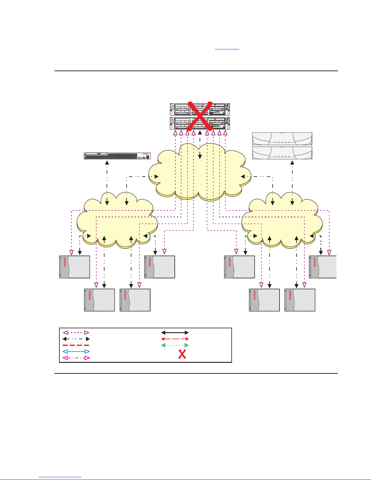
Example 1: Main servers fail
In Example 1, (see Figure 1) the S8710 Media Server is acting as the Main server in an ESS
environment. Two ESS servers have been positioned in the network. Through administration on
the Main server, an S8700 Media Server has been selected as the primary backup to the Main
server. An S8500 Media Server is acting as a secondary backup in case of an S8700 ESS
server failure or WAN fragmentation. The intent of the ESS configuration for Example 1 is to
keep all Port Networks under the control of a single server.
ESS failover examples
Issue 1.1 June 2005 23

ESS Overview
Figure 1: S8710 Media Server with ESS servers in normal operation
S8500 ESS Server
(2nd Alternative)
disc
S8710 Media Server
(Main Server)
COMPACT
disc
1
3
5
5
4
4
5
5
4
4
1
3
0
2
0
2
COMPACT
disc
1
3
3
1
0
2
2
0
2
ch
1
1
2
ch
x
e
UID
l
p
u
D
x
e
l
p
m
i
S
2
ch
1
1
2
ch
x
e
UID
l
p
u
D
x
e
l
p
m
i
S
S8700 ESS Server
(1st Alternative)
PN #1 PN #5
PN #4 PN #8
PN #2 PN #6PN #3 PN #7
Port Network Control Link (EAL)
IP Connection into Control Network
Server or Network Failure
VoIP Path
DSIC LInk
cycmsrv3 KLC 031505
CSS / EI (Fiber)
ATM / ATM-EI (Fiber)
Dup Link
Out of Service
24 Avaya Enterprise Survivable Servers (ESS) Users Guide
ESS failover examples
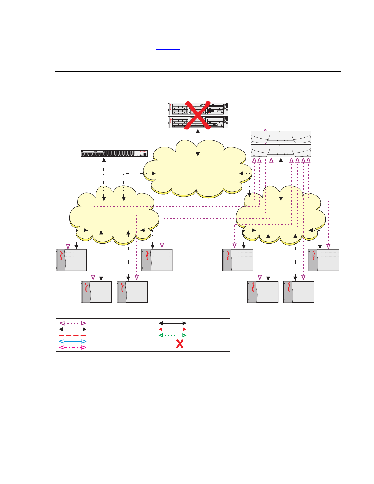
A catastrophic failure occurs on the Main servers (see Figure 2). The IPSIs in every IPSI
controlled Port Network can no longer communicate with the Main server. The no service timer
activates.
Figure 2: Catastrophic Main server failure
S8710 Media Server
S8500 ESS Server
(2nd Alternative)
disc
(Main Server)
5
5
4
4
5
5
4
4
COMPACT
2
disc
ch
1
1
2
ch
x
e
UID
l
p
u
D
1
3
3
1
x
e
l
p
m
i
S
0
2
2
0
COMPACT
2
disc
ch
1
1
2
ch
x
e
UID
l
p
u
D
1
3
3
1
x
e
l
p
m
i
S
0
2
2
0
S8700 ESS Server
(1st Alternative)
PN #1 PN #5
PN #4 PN #8
PN #2 PN #6PN #3 PN #7
Port Network Control Link (EAL)
IP Connection into Control Network
Server or Network Failure
VoIP Path
DSIC LInk
cycmcmsf KLC 031505
CSS / EI (Fiber)
ATM / ATM-EI (Fiber)
Dup Link
Out of Service
When ESS was administered on the Main server, the S8700 ESS server received higher values
than the S8500 ESS server. The administered values of the ESS servers were advertised to the
IPSIs in the configuration. Based on the values of the ESS servers, the IPSI places the S8700
ESS server higher on its priority list then the S8500 ESS server.
Issue 1.1 June 2005 25
ESS Overview
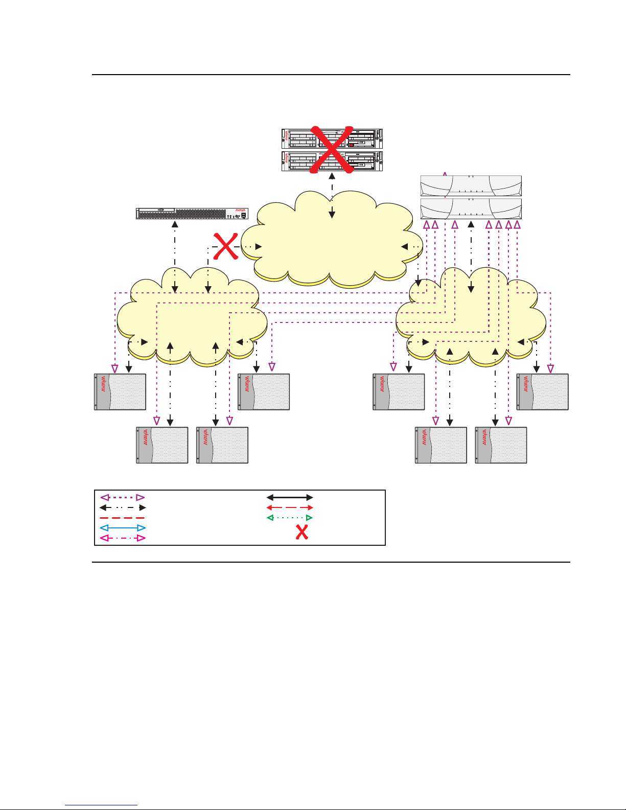
The no service timer expires (see Figure 3), the IPSIs request service from the highest ESS
server on its list (S8700 ESS server). The S8700 ESS server acknowledges the request and
takes control of the IPSI controlled Port Networks.
Figure 3: Main servers fail- ESS recovery of failure
S8500 ESS Server
(2nd Alternative)
disc
S8710 Media Server
(Main Server)
COMPACT
disc
1
3
5
3
5
4
4
5
5
4
4
1
0
2
2
0
COMPACT
disc
1
3
3
1
0
2
2
0
2
ch
1
1
2
ch
x
e
UID
l
p
u
D
x
e
l
p
m
i
S
2
ch
1
1
2
ch
x
e
UID
l
p
u
D
x
e
l
p
m
i
S
S8700 ESS Server
(1st Alternative)
PN #1 PN #5
PN #4 PN #8
PN #2 PN #6PN #3 PN #7
Port Network Control Link (EAL)
IP Connection into Control Network
Server or Network Failure
VoIP Path
DSIC LInk
cycmer1 KLC 031505
CSS / EI (Fiber)
ATM / ATM-EI (Fiber)
Dup Link
Out of Service
26 Avaya Enterprise Survivable Servers (ESS) Users Guide

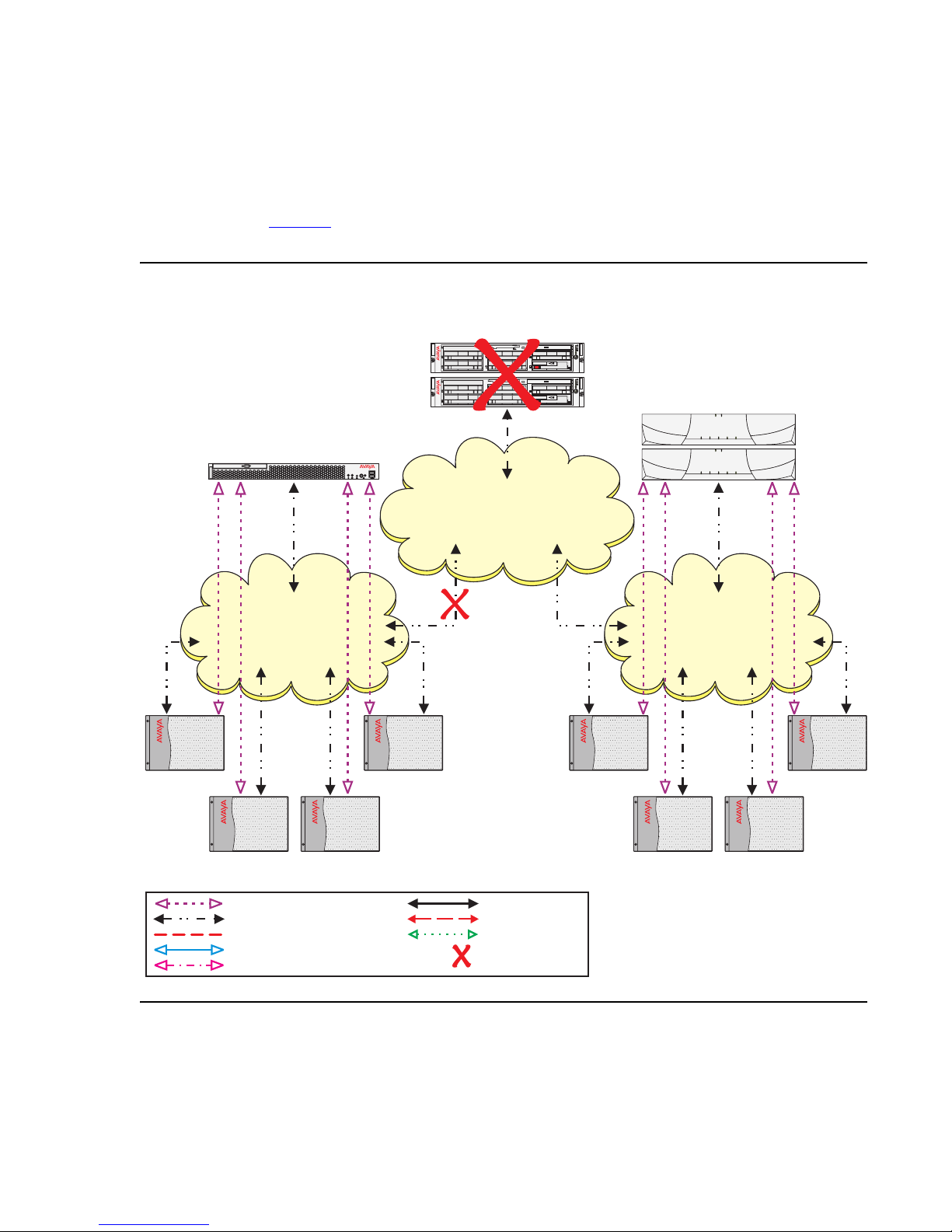
Example 2: Network failure
Example 2 uses the same configuration used in Example 1. The S8710 Media Server is the
Main server, an S8700 ESS server is administered as the first priority ESS server, and the
S8500 ESS server is administered as the second priority ESS server. Due to a catastrophic
failure the Main server is out-of-service. All Port Networks are now controlled by the S8700 ESS
server.
Up to this point this is the same scenario at example 1. Now, the customer experiences a
network outage resulting in a fragmentation (see Figure 4
communicate with the S8500 ESS server, but can no longer communicate with the Main server
or the S8700 ESS server. Port Networks 5 through 8 can still communicate with the S8700 ESS
server but can no longer communicate with the S8500 ESS server.
ESS failover examples
). Port Networks 1 through 4 can
Issue 1.1 June 2005 27
ESS Overview
Figure 4: Network fragmentation failure
S8500 ESS Server
(2nd Alternative)
disc
S8710 Media Server
(Main Server)
COMPACT
disc
1
3
5
3
5
4
4
5
5
4
4
1
0
2
2
0
COMPACT
disc
1
3
3
1
0
2
2
0
2
ch
1
1
2
ch
x
e
UID
l
p
u
D
x
e
l
p
m
i
S
2
ch
1
1
2
ch
x
e
UID
l
p
u
D
x
e
l
p
m
i
S
S8700 ESS Server
(1st Alternative)
PN #1 PN #5
PN #4 PN #8
PN #2 PN #6PN #3 PN #7
Port Network Control Link (EAL)
IP Connection into Control Network
Server or Network Failure
VoIP Path
DSIC LInk
cycmnff KLC 031505
CSS / EI (Fiber)
ATM / ATM-EI (Fiber)
Dup Link
Out of Service
28 Avaya Enterprise Survivable Servers (ESS) Users Guide
ESS failover examples
Because the IPSIs in Port Networks 1 through 4 cannot communicate with the Main server or
the S8700 ESS server, they adjust their priority list and move the S8500 ESS server to the top
of the list. The no service timer activates for Port Networks 1 through 4. When the no service
timer expires, the IPSIs in Port Networks 1 through 4 request service from the S8500 ESS
server. The S8500 ESS server acknowledges the request and assumes control of Port Network
1 through 4 (see Figure 5
). Note that Port Networks 5 through 8 did not experience any service
outage from the failure.
Figure 5: Network failure - ESS recovery
S8710 Media Server
S8500 ESS Server
(2nd Alternative)
disc
(Main Server)
5
5
4
4
5
5
4
4
COMPACT
2
disc
ch
1
1
2
ch
x
e
UID
l
p
u
D
1
3
3
1
x
e
l
p
m
i
S
0
2
2
0
COMPACT
2
disc
ch
1
1
2
ch
x
e
UID
l
p
u
D
1
3
3
1
x
e
l
p
m
i
S
0
2
2
0
S8700 ESS Server
(1st Alternative)
PN #1 PN #5
PN #2 PN #6PN #3 PN #7
Port Network Control Link (EAL)
IP Connection into Control Network
Server or Network Failure
VoIP Path
DSIC LInk
cycmerf2 KLC 031505
PN #4 PN #8
CSS / EI (Fiber)
ATM / ATM-EI (Fiber)
Dup Link
Out of Service
Issue 1.1 June 2005 29

ESS Overview
The users in Port Network 1 through 4 experience the following:
● During the no service timer interval:
● After the no service timer expires
The customer is now in the process of recovering from both the network failure and the Main
server failure (see Figure 6
4 can now communicate with the S8700 ESS server. The IPSI priority list adjusts to reflect the
S8700 ESS server as the highest priority ESS server. Even though the IPSI priority list now
shows the S8700 ESS server as its highest priority ESS server, the Port Networks do not
automatically return to the control of the S8700 ESS server. Moving the Port Networks from the
S8500 ESS server to another ESS server requires manual intervention using the get
forced-takeover ipsi-interface command or scheduling the Auto Return
functionality. For information on the get forced-takeover ipsi-interface command
see, get forced-takeover ipserver-interface
Auto Return functionality see, System-parameters ess form - page seven
page 126.
- Stable calls remain up in the same state as they were before the outage occurred. The
stable calls do not have access to any features such as hold, conference, etc. The state
of the stable call cannot be changed.
- Users attempting to originate a telephone call do not get dial tone.
- Incoming calls to the system receive a fast busy (reorder tone) or an announcement from
the facility provider saying all circuits are busy.
- Users on an IP connected phone call: Shuffled IP calls will stay up. Once the call
terminates, the user of the IP telephone will not be able to make another call until the IP
telephone re-registers with a gatekeeper.
- Calls on DCP or analog phones terminates
). As the network failure is fixed, the IPSIs in Port Network 1 through
on page 152. For information on the
on
30 Avaya Enterprise Survivable Servers (ESS) Users Guide
 Loading...