

Page 1

Avaya Application Solutions:
IP Telephony Deployment Guide
555-245-600
Issue 3.4.1
June 2005
Page 2

Copyright 2005, Avaya Inc.
All Rights Reserved
Notice
Every efIssue 3.4.1plete and accurate at the time of printing. However,
information is subject to change.
Warranty
Avaya Inc. provides a limited warranty on this product. Refer to your
sales agreement to establish the terms of the limited warranty. In
addition, Avaya’s standard warranty language as well as information
regarding support for this product, while under warranty, is available
through the following Web site: http://www.avaya.com/support
Preventing Toll Fraud
"Toll fraud" is the unauthorized use of your telecommunications system
by an unaut horized party (for example, a person who is not a corporate
employee, agent, subcontractor, or is not working on your company's
behalf). Be aware that there may be a risk of toll fraud associated with
your system and that, if toll fraud occurs, it can result in substantial
additional charges for your telecommunications services.
Avaya Fraud Intervention
If you suspect that you are being victimized by toll fraud and you need
technical assistance or support, in the United States and Canada, call the
Technical Service Center's Toll Fraud Intervention Hotline at
1-800-643-2353.
Disclaimer
Avaya is not responsible for any modifications, additions or deletions to
the original published version of this documentation unless such
modifications, additions or deletions were performed by Avaya. Customer
and/or End User agree to indemnify and hold harmless Avaya, Avaya's
agents, servants and employees against all claims, lawsuits, demands
and judgments arising out of, or in connection with, subsequent
modifications, additions or deletions to this documentation to the extent
made by the Customer or End User.
How to Get Help
For additional support telephone numbers, go to the Avaya support Web
site: http://www.avaya.com/support
• Within the United States, click the Escalation Contacts link.
Then click the appropriate link for the type of support you
need.
• Outside the United States, click the Escalation Contacts link.
Then click the International Services link that includes
telephone numbers for the international Centers of
Excellence.
Providing Telecommunications Security
Telecommunications security (of voice, data, and/or video
communications) is the prevention of any type of intrusion to (that is,
either unauthorized or malicio us access to or use of) your company's
telecommunications equ ipm ent by some part y.
Your company's "telecommunications equipment" includes both this
Avaya product and any other voice/data/video equipment that could be
accessed using this Avaya product (that is, "networked equipment").
An "outside party" is anyone who is not a corporate employee, agent,
subcontractor, or is not working on your company's behalf. Whereas, a
"malicious party" is anyone (including someone who may be otherwise
authorized) who accesses your telecommunications equipment with
either malicious or mischievous intent.
Such intrusions may be either to/through synchronous (time-multiplexed
and/or circuit-based), or asynchronous (character-, message-, or
packet-based) equipment, or interfaces for reasons of:
• Utilization (of capabilities special to the accessed equipment)
• Theft (such as, of intellectual property, financial assets, or toll
facility access)
• Eavesdropping (privacy invasions to humans)
• Mischief (troubling, but apparently innocuous, tampering)
• Harm (such as harmful tampering, data loss or alteration,
Be aware that there may be a risk of unauthorized intrusions associated
with your system and/or its networked equipment. Also realize that, if
such an intrusion should occur, it could result in a variety of losses to your
company (including but not limited to, human/data privacy, intellectual
property, material assets, financial resources, labor costs, and/or legal
costs).
regardless of motive or intent)
. If you are:
.
Responsibility for Your Company’s Telecommunications Security
The final responsibility for securing both this system and its networked
equipment rests with you - Avaya’s customer system administrator, your
telecommunications peers, and your managers. Base the fulfillment of
your responsibility on acquired knowledge and resources from a variety
of sources including but not limited to:
• Installation docume nts
• System administration documents
• Security documents
• Hardware-/software-based security tools
• Shared information between you and your peers
• Telecommunications security experts
To prevent intrusions to your telecommunications equipment, you and
your peers should carefully program and configure:
• Your Avaya-provided telecommunications systems and their
interfaces
• Your Avaya-provided software applications, as well as their
underlying hardware/software platforms and interfaces
• Any other equipment networked to your Avaya products
TCP/IP Facilities
Customers may ex perien ce dif fer ences i n prod uct p erforma nce, relia bili ty
and security depending upon network configurations/design and
topologies, even when the product performs as warranted.
Standards Compliance
Avaya Inc. is not responsible for any radio or television interference
caused by unauthorized modifications of this equipment or the
substitution or attachment of connec ting cab le s and equ ipme nt oth er
than those specified by Avaya Inc. The correction of interference caused
by such unauthorized modifications, substitution or attachment will be the
responsibility of the user. Pursuant to Part 15 of the Federal
Communications Commission (FCC) Rules, the user is cautioned that
changes or modifications not expressly approved by Avaya Inc. could
void the user’s authority to operate this equipment.
Product Safety Standards
This product complies with and conforms to the following international
Product Safety standards as applicable:
Safety of Information Technology Equipment, IEC 60950, 3rd Edition, or
IEC 60950-1, 1st Edition, including all relevant national deviations as
listed in Compliance with IEC for Electrical Equipment (IECEE) CB-96A.
Safety of Information Technology Equipment, CAN/CSA-C22.2
No. 60950-00 / UL 60950, 3rd Edition, or CAN/CSA-C22.2 No.
60950-1-03 / UL 60950-1.
Safety Requirements for Information Technology Equipment, AS/NZS
60950:2000.
One or more of the following Mexican national standards, as applicable:
NOM 001 SCFI 1993, NOM SCFI 016 1993, NOM 019 SCFI 1998.
The equipment described in this document may contain Class 1 LASER
Device(s). These devices comply with the following standards:
• EN 60825-1, Edition 1.1, 1998-01
• 21 CFR 1040.10 and CFR 1040.11.
The LASER devices used in Av aya equipment typi cally operate within t he
following parameters:
Typical Center Wavelength Maximum Output Power
830 nm - 860 nm -1.5 dBm
1270 nm - 1360 nm -3.0 dBm
1540 nm - 1570 nm 5.0 dBm
Luokan 1 Laserlaite
Klass 1 Laser Apparat
Use of controls or adjustments or performance of procedures other than
those specified herein may result in hazardous radiation exposures.
Contact your Avaya representative for more laser product info rmation.
Page 3

Electromagnetic Compatibility (EMC) Standards
This product complies with and conforms to the following international
EMC standards and all relevant national deviations:
Limits and Methods of Measurement of Radio Interference of Information
Technology Equipment, CISPR 22:1997, EN55022:1998, and AS/NZS
3548.
Information Technology Equipment - Immunity Characteristics - Limits
and Methods of Measurement, CISPR 24:1997 and EN55024:1998,
including:
• Electrostatic Discharge (ESD) IEC 61000-4-2
• Radiated Immunity IEC 61000-4-3
• Electrical Fast Transient IEC 61000-4-4
• Lightning Effects IEC 61000-4-5
• Conducted Immunity IEC 61000-4-6
• Mains Frequency Magnetic Field IEC 61000-4-8
• Voltage Dips and Variations IEC 61000-4-11
Power Line Emissions, IEC 61000-3-2: Electromagnetic compatibility
(EMC) - Part 3-2: Limits - Limits for harmonic current emissions.
Power Line Emissions, IEC 61000-3-3: Electromagnetic compatibility
(EMC) - Part 3-3: Limits - Limitation of voltage changes, voltage
fluctuations and flicker in public low-voltage supply systems.
Federal Communications Commission Statement
Part 15:
Note: This e qui pm en t ha s b ee n te ste d a nd fo un d t o c omp ly w it h
the limit s for a Class A digital device, pursuant to Part 15 of the
FCC Rules. These limits are designed to provide reasonable
protection against harmful interference when the equipment is
operated in a commercial environment. This equipment
generates, uses, and can radiate radio frequency energy and, if
not installed and used in accordance w ith the instruction
manual, may cause harmful interference to radio
communications. Operation of this equipment in a residential
area is likely to cause harmful interference in which case the
user will be required to cor rect the interference at his own
expense.
Part 68: Answer-Supervision Signaling
Allowing this equipment to be operated in a manner that does not provide
proper answer-supervision signaling is in violation of Part 68 rules. This
equipment returns answer-supervision signals to the public switched
network when:
• answered by the called station,
• answered by the attendant, or
• routed to a recorded announcement that can be administered
by the customer premises equipment (CPE) user.
This equipment returns answer-supervision signals on all direct inward
dialed (DID) calls forwarded back to the public switched telephone
network. Permissible exceptions are:
• A call is unanswered.
• A busy tone is received.
• A reorder tone is received.
Avaya at test s tha t thi s r egis te red eq ui pmen t is cap ab le o f pr ovid in g user s
access to interstate providers of operator services through the use of
access codes. Modification of this equipment by call aggregators to block
access dialing codes is a violation of the Telephone Operator Consumers
Act of 1990.
REN Number
For MCC1, SCC1, CMC1, G600, and G650 Media Gateways:
This equipment complies with Part 68 of the FCC rules. On either the
rear or inside the front cover of this equipment is a label that contains,
among other information, the FCC registration number, and ringer
equivalence number (REN) for this equipment. If requested, this
information must be provided to the telephone company.
For G350 and G700 Media Gateways:
This equipment complies with Part 68 of the FCC rules and the
requirements adopted by the ACTA. On the rear of this equipment is a
label that contains, among other information, a product identifier in the
format US:AAAEQ##TXXXX. The digits represented by ## are the ringer
equivalence number (REN) without a decimal point (for example, 03 is a
REN of 0.3). If requested, this number must be provided to the telephone
company.
For all media gateways:
The REN is used to determine the quantity of devices that may be
connected to the telephone line. Excessive RENs on the telephone line
may result in devices not ringing in response to an incoming call. In most,
but not all areas, the sum of RENs should not exceed 5.0. To be certain
of the number of devices that may be connected to a line, as determined
by the total RENs, contact the local telephone company.
REN is not required for some types of analog or digital facilities.
Means of Connection
Connection of this equipment to the telephone network is shown in the
following tables.
For MCC1, SCC1, CMC1, G600, and G650 Media Gateways:
Manufacturer’s Port
Identifier
Off premises station OL13C 9.0F RJ2GX,
DID trunk 02RV2-T 0.0B RJ2GX,
CO trunk 02GS2 0.3A RJ21X
Tie trunk TL31M 9.0F R J2GX
Basic Rate Interface 02IS5 6.0F, 6.0Y RJ49C
1.544 digital interface 04DU9-BN 6.0F RJ48C,
120A4 channel service
unit
For G350 and G700 Media Gateways:
Manufacturer’s Port
Identifier
Ground Start CO trunk 02GS2 1.0A RJ11C
DID trunk 02RV2-T AS.0 RJ11C
Loop Start CO trunk 02LS2 0.5A RJ11C
1.544 digital interface 04DU9-BN 6 .0Y R J48C
Basic Rate Interface 02IS5 6.0F RJ49C
For all media gateways:
If the terminal equipment (for example, the media server or media
gateway) causes harm to the telephone network, the telephone company
will notify you in advance that temporary discontinuance of service may
be required. But if advance notice is not practical, the telephone
company will notify the customer as soon as possible. Also, you will be
advised of your right to file a complaint with the FCC if you believe it is
necessary.
The telephone company may make changes in its facilities, equipment,
operations or procedures that could affect the operation of the
equipment. If this happens, the telephone company will provide advance
notice in order for you to make necessary modifications to maintain
uninterrupted service.
If trouble is experienced with this equipment, for repair or warranty
information, please contact the Technical Service Center at
1-800-242- 2121 or contact your local Avaya representative. If the
equipment is causing harm to the telephone network, the telephone
company may request that you disconnect the equipment until the
problem is resolved.
FIC Code SOC/
02LS2 0.3A RJ21X
04DU9-IKN 6.0F RJ48C,
04DU9-ISN 6.0F RJ48C,
04DU9-DN 6.0Y RJ48C
FIC Code SOC/
04DU9-DN 6.0Y RJ48C
04DU9-IKN 6.0Y RJ48C
04DU9-ISN 6.0Y RJ48C
REN/
A.S. Code
REN/
A.S. Code
Network
Jacks
RJ21X,
RJ11C
RJ21X
RJ48M
RJ48M
RJ48M
Network
Jacks
Page 4

A plug and jack used to connect this equipment to the premises wiring
and telephone network must comply with the applicable FCC Part 68
rules and requirements adopted by the ACTA. A compliant telephone
cord and modular plug is provided with this product. It is designed to be
connected to a compatible modular jack that is also compliant. It is
recommended that repairs be performed by Avaya certified technicians.
The equipment cannot be used on public coin phone service provided by
the telephone company. Connection to party line service is subject to
state tariffs. Contact the state public utility commission, public service
commission or corpor ation commission for information.
This equipment, if it uses a telephone receiver, is hearing aid compatible.
Canadian Department of Communic ations (DOC) Interference
Information
This Class A digital apparatus complies with Canadian ICES-003.
Cet appareil numérique de la classe A est conforme à la norme
NMB-003 du Canada.
This equipment meets the applicable Industry Canada Terminal
Equipment Technical Specifications. This is confirmed by the registration
number. The abbreviation, IC, before the registration number signifies
that registration was performed based on a Declaration of Conformity
indicating that Industry Canada technical specifications were met. It does
not imply that Industry Canada approved the equipment.
Installation and Repairs
Before installing this equipment, users should ensure that it is
permissible to be connected to the facilities of the local
telecommunications company. The equipment must also be installed
using an acceptable method of connection. The customer should be
aware that compliance with the above conditions may not prevent
degradation of service in some situations.
Repairs to certified equipment should be coordinated by a representative
designated by the supplier. Any repairs or alterations made by the user to
this equipment, or equipment malfunctions, may give the
telecommunications co mpany cause to request the user to disconnect
the equipment.
Declarations of Conformity
United States FCC Part 68 Supplier’s Declaration of Conformity (SDoC)
Avaya Inc. in the United States of America hereby certifies that the
equipment described in this document and bearing a TIA TSB-168 label
identification number complies with the FCC’s Rules and Regulations 47
CFR Part 68, and the Administrative Council on Terminal Attachments
(ACTA) adopted technical criteria.
Avaya further asserts that Avaya handset-equipped terminal equipment
described in this document complies with Paragraph 68.316 of the FCC
Rules and Regulations defining Hearing Aid Compatibility and is deemed
compatible with hearing aids.
Copies of SDoCs signed by the Responsible Party in the U. S. can be
obtained by contacting your local sales representative and are available
on the following Web site: http://www.avaya.com/support
All Avaya media servers and media gateways are compliant with FCC
Part 68, but many have been registered with the FCC before the SDoC
process was available. A list of all Avaya registered products may be
found at: http://www.part68.org
manufacturer.
European Union Declarations of Conformity
by conducting a search using "Avaya" as
.
To order copies of this and other documents:
Call: Avaya Publications Center
Voice 1.800.457.1235 or 1.207.866.6701
FAX 1.800.457.1764 or 1.207.626.72 69
Write: Globalware Solutions
200 Ward Hill Avenue
Haverhill, MA 01835 USA
Attention: Avaya Account Manage ment
E-mail: [email protected]
For the most current versions of documentation, go to the Avaya support
Web site: http://www.avaya.com/support
.
Avaya Inc. declares that the equipment specified in this document
bearing the "CE" (Conformité Europeénne) mark conforms to the
European Union Radio and Telecommunications Terminal Equipment
Directive (1999/5/EC), including the Electromagnetic Compatibility
Directive (89/336/EEC) and Low Voltage Directive (73/23/EEC).
Copies of these Declarations of Conform ity (DoCs) can be obtai ne d by
contacting your local sales representative and are available on the
following Web site: http://www.avaya.com/support
Japan
This is a Class A product based on the standard of the Voluntary Control
Council for Interference by Information Technology Equipment (VCCI). If
this equipment is used in a domestic environment, radio disturbance may
occur, in which case, the user may be required to take corrective actions.
.
Page 5

Contents
About This Book. . . . . . . . . . . . . . . . . . . . . . . . . . . . . . . 15
Overview . . . . . . . . . . . . . . . . . . . . . . . . . . . . . . . . . . . . . . . . 15
Audience . . . . . . . . . . . . . . . . . . . . . . . . . . . . . . . . . . . . . . . . 15
Using this book . . . . . . . . . . . . . . . . . . . . . . . . . . . . . . . . . . . . 16
Downloading this book and updates from the Web . . . . . . . . . . . . . . . . . 17
Downloading this book . . . . . . . . . . . . . . . . . . . . . . . . . . . . . . 17
Related resources . . . . . . . . . . . . . . . . . . . . . . . . . . . . . . . . . . . 17
Technical assistance . . . . . . . . . . . . . . . . . . . . . . . . . . . . . . . . . 18
Within the US. . . . . . . . . . . . . . . . . . . . . . . . . . . . . . . . . . . . 18
International . . . . . . . . . . . . . . . . . . . . . . . . . . . . . . . . . . . . 18
Trademarks. . . . . . . . . . . . . . . . . . . . . . . . . . . . . . . . . . . . . . . 18
Sending us comments. . . . . . . . . . . . . . . . . . . . . . . . . . . . . . . . . 19
Section 1: Avaya Application Solutions
product guide . . . . . . . . . . . . . . . . . . . . . . . 21
Avaya Application Solutions . . . . . . . . . . . . . . . . . . . . . . . . 23
Avaya Communication Manager . . . . . . . . . . . . . . . . . . . . . . . . . . . 25
Avaya Media Servers . . . . . . . . . . . . . . . . . . . . . . . . . . . . . . . 25
Avaya DEFINITY Servers . . . . . . . . . . . . . . . . . . . . . . . . . . . . . 26
Avaya Media Gateways . . . . . . . . . . . . . . . . . . . . . . . . . . . . . . 26
Avaya Integrated Management . . . . . . . . . . . . . . . . . . . . . . . . . . 27
Avaya communication devices . . . . . . . . . . . . . . . . . . . . . . . . . . 28
Avaya Communication Manager applications . . . . . . . . . . . . . . . . . . 28
Avaya Application Solutions platforms . . . . . . . . . . . . . . . . . . 31
Small to mid-size enterprise . . . . . . . . . . . . . . . . . . . . . . . . . . . . . 33
Avaya S8300 Media Server and Avaya G700
or G350 Media Gateway . . . . . . . . . . . . . . . . . . . . . . . . . . . . . 33
DEFINITY Server CSI and CMC1 Media Gateway . . . . . . . . . . . . . . . . 45
DEFINITY Server SI
and SCC1 or MCC1 Media Gateway . . . . . . . . . . . . . . . . . . . . . . . 45
Mid-market to large enterprise . . . . . . . . . . . . . . . . . . . . . . . . . . . . 46
S8500 Media Server . . . . . . . . . . . . . . . . . . . . . . . . . . . . . . . . 46
S8700 Media Server Multi-Connect configurati on. . . . . . . . . . . . . . . . 48
Avaya S8700 series Media Server IP-Connect configurati on. . . . . . . . . . 65
DEFINITY Servers R and SI . . . . . . . . . . . . . . . . . . . . . . . . . . . . 71
S8710 Media Server . . . . . . . . . . . . . . . . . . . . . . . . . . . . . . . . 71
Service Provider — Blade Server. . . . . . . . . . . . . . . . . . . . . . . . . 72
Issue 3.4.1 June 2005 5
Page 6

Other Avaya IP Telephony servers . . . . . . . . . . . . . . . . . . . . . . . . . . 73
Avaya IP Office. . . . . . . . . . . . . . . . . . . . . . . . . . . . . . . . . . . 73
Greenfield deployment . . . . . . . . . . . . . . . . . . . . . . . . . . . 75
Components needed for Greenfield deployment . . . . . . . . . . . . . . . . . . 75
Media Server (H.323 Gatekeeper). . . . . . . . . . . . . . . . . . . . . . . . . 76
Avaya Communication Manager . . . . . . . . . . . . . . . . . . . . . . . . . 77
Media Gateways and Port Networks . . . . . . . . . . . . . . . . . . . . . . . 77
Greenfield configurations. . . . . . . . . . . . . . . . . . . . . . . . . . . . . . . 78
S8300 / G700 / G350 standalone (small-to-midsize enterprise). . . . . . . . . 78
Medium-to-large enterprise solutions . . . . . . . . . . . . . . . . . . . . . . 79
Required circuit packs for S8700 configuration. . . . . . . . . . . . . . . . . 81
Evolution from circuit-switched to IP . . . . . . . . . . . . . . . . . . . 85
Migration from DEFINITY
Server R to S8700 Multi-Connect . . . . . . . . . . . . . . . . . . . . . . . . . . 86
Phase 1: Processor replacement . . . . . . . . . . . . . . . . . . . . . . . . . 86
Phase 2: IP-enable the Port Networks to support IP endpoints . . . . . . . . 88
Phase 3: Server consolidation . . . . . . . . . . . . . . . . . . . . . . . . . . 89
Call processing . . . . . . . . . . . . . . . . . . . . . . . . . . . . . . . 91
Communication Manager capabilities . . . . . . . . . . . . . . . . . . . . . . . . 91
Voice and multimedia networking . . . . . . . . . . . . . . . . . . . . . . . . . . 92
Intelligent networking and call routing. . . . . . . . . . . . . . . . . . . . . . 92
IP Port Network / Media Gateway connectivity . . . . . . . . . . . . . . . . . 92
H.248 Media Gateway control. . . . . . . . . . . . . . . . . . . . . . . . . . . 92
Call Processing . . . . . . . . . . . . . . . . . . . . . . . . . . . . . . . . . . . . 92
Communication Manager gatekeepers. . . . . . . . . . . . . . . . . . . . . . 92
Call signaling. . . . . . . . . . . . . . . . . . . . . . . . . . . . . . . . . . . . 94
Media stream handling . . . . . . . . . . . . . . . . . . . . . . . . . . . . . . 94
Separation of Bearer and Signaling (SBS). . . . . . . . . . . . . . . . . . . . 96
Multi-location. . . . . . . . . . . . . . . . . . . . . . . . . . . . . . . . . . . . 96
Modem/Fax/TTY over IP . . . . . . . . . . . . . . . . . . . . . . . . . . . . . . 97
IP-based trunks . . . . . . . . . . . . . . . . . . . . . . . . . . . . . . . . . . . . 99
IP tie trunks . . . . . . . . . . . . . . . . . . . . . . . . . . . . . . . . . . . . 100
Trunk signaling . . . . . . . . . . . . . . . . . . . . . . . . . . . . . . . . . . 100
SIP . . . . . . . . . . . . . . . . . . . . . . . . . . . . . . . . . . . . . . . . . . . 100
Converged Communication Server. . . . . . . . . . . . . . . . . . . . . . . . . . 101
6 Avaya Application Solutions IP Telephony Deployment Guide
Page 7

Mobility . . . . . . . . . . . . . . . . . . . . . . . . . . . . . . . . . . . . . . . . . 102
IP Telephones or IP Softphones . . . . . . . . . . . . . . . . . . . . . . . . . 102
Extension to Cellular . . . . . . . . . . . . . . . . . . . . . . . . . . . . . . . 102
Communication applications . . . . . . . . . . . . . . . . . . . . . . . . . . . . . 103
Call Center . . . . . . . . . . . . . . . . . . . . . . . . . . . . . . . . . . . . . 103
Computer Telephony Integration (CTI). . . . . . . . . . . . . . . . . . . . . . 104
Application Programming Interfaces (APIs) . . . . . . . . . . . . . . . . . . . 104
Best Services Routing (BSR) polling. . . . . . . . . . . . . . . . . . . . . . . 105
Meet-me conferencing. . . . . . . . . . . . . . . . . . . . . . . . . . . . . . . 105
Avaya LAN switching products. . . . . . . . . . . . . . . . . . . . . . . 107
Converged infrastructure LAN switches. . . . . . . . . . . . . . . . . . . . . . . 107
C360 converged stackable switches . . . . . . . . . . . . . . . . . . . . . . . 107
P330 Ethernet stackable switch . . . . . . . . . . . . . . . . . . . . . . . . . 112
C460 converged multi-layer switch. . . . . . . . . . . . . . . . . . . . . . . . 117
Avaya Power over Ethernet (PoE) switches . . . . . . . . . . . . . . . . . . . 118
Midspan Power Unit . . . . . . . . . . . . . . . . . . . . . . . . . . . . . . . . . . 119
Description. . . . . . . . . . . . . . . . . . . . . . . . . . . . . . . . . . . . . 119
Converged infrastructure security gateways . . . . . . . . . . . . . . . . . . . . 121
VSUs . . . . . . . . . . . . . . . . . . . . . . . . . . . . . . . . . . . . . . . . 121
VPN Client . . . . . . . . . . . . . . . . . . . . . . . . . . . . . . . . . . . . . 123
Terminals . . . . . . . . . . . . . . . . . . . . . . . . . . . . . . . . . . 125
Avaya IP Softphone . . . . . . . . . . . . . . . . . . . . . . . . . . . . . . . . . . 125
Softphone operating modes . . . . . . . . . . . . . . . . . . . . . . . . . . . 126
Avaya IP Agent. . . . . . . . . . . . . . . . . . . . . . . . . . . . . . . . . . . . . 127
Avaya Softconsole. . . . . . . . . . . . . . . . . . . . . . . . . . . . . . . . . . . 128
Avaya IP Softphone for Pocket PC . . . . . . . . . . . . . . . . . . . . . . . . . . 128
Features . . . . . . . . . . . . . . . . . . . . . . . . . . . . . . . . . . . . . . 129
Avaya 4600 Series IP Telephones. . . . . . . . . . . . . . . . . . . . . . . . . . . 130
Networking coordination . . . . . . . . . . . . . . . . . . . . . . . . . . . . . 132
Features and applications. . . . . . . . . . . . . . . . . . . . . . . . . . . . . 133
Communication Manager support for the 4600 IP Telephone Series . . . . . 137
Wireless . . . . . . . . . . . . . . . . . . . . . . . . . . . . . . . . . . . . . . . . 138
Avaya Extension to Cellular. . . . . . . . . . . . . . . . . . . . . . . . . . . . 138
Other digital wireless systems . . . . . . . . . . . . . . . . . . . . . . . . . . 138
Issue 3.4.1 June 2005 7
Page 8

Section 2: Deploying IP Telephony . . . . . . . . . . . . . . . . . . 139
Traffic engineering . . . . . . . . . . . . . . . . . . . . . . . . . . . . . 141
Introduction . . . . . . . . . . . . . . . . . . . . . . . . . . . . . . . . . . . . . . 141
Design inputs . . . . . . . . . . . . . . . . . . . . . . . . . . . . . . . . . . . . . 142
Topology . . . . . . . . . . . . . . . . . . . . . . . . . . . . . . . . . . . . . . 142
Endpoint specifications . . . . . . . . . . . . . . . . . . . . . . . . . . . . . . 144
Endpoint traffic usage. . . . . . . . . . . . . . . . . . . . . . . . . . . . . . . 144
Call usage rates . . . . . . . . . . . . . . . . . . . . . . . . . . . . . . . . . . . . 146
Communities of interest. . . . . . . . . . . . . . . . . . . . . . . . . . . . . . 147
Expanded COI matrices . . . . . . . . . . . . . . . . . . . . . . . . . . . . . . 155
COIs for multiple-site networks. . . . . . . . . . . . . . . . . . . . . . . . . . 161
Resource sizing . . . . . . . . . . . . . . . . . . . . . . . . . . . . . . . . . . . . 162
Overview . . . . . . . . . . . . . . . . . . . . . . . . . . . . . . . . . . . . . . 162
Signaling resources . . . . . . . . . . . . . . . . . . . . . . . . . . . . . . . . 163
Media processing and TDM resources. . . . . . . . . . . . . . . . . . . . . . 163
TN2312 IPSI circuit packs . . . . . . . . . . . . . . . . . . . . . . . . . . . . . 174
Processing occupancy . . . . . . . . . . . . . . . . . . . . . . . . . . . . . . 175
IP Bandwidth and Call Admission Control. . . . . . . . . . . . . . . . . . . . 176
Physical resource placement . . . . . . . . . . . . . . . . . . . . . . . . . . . 185
Final checks and adjustments . . . . . . . . . . . . . . . . . . . . . . . . . . 185
Security . . . . . . . . . . . . . . . . . . . . . . . . . . . . . . . . . . 187
Your security policy . . . . . . . . . . . . . . . . . . . . . . . . . . . . . . . . . . 187
Avaya Communication
Manager and Media Servers . . . . . . . . . . . . . . . . . . . . . . . . . . . . . 189
LAN isolation configurations . . . . . . . . . . . . . . . . . . . . . . . . . . . 193
Virus and worm protection . . . . . . . . . . . . . . . . . . . . . . . . . . . . 196
IP Telephony circuit pack security . . . . . . . . . . . . . . . . . . . . . . . . . . 198
TN2312 IP Server Interface (IPSI) . . . . . . . . . . . . . . . . . . . . . . . . . 198
TN2302 Media Processor (MedPro). . . . . . . . . . . . . . . . . . . . . . . . 199
TN799 Control LAN (C-LAN) . . . . . . . . . . . . . . . . . . . . . . . . . . . 200
Toll fraud . . . . . . . . . . . . . . . . . . . . . . . . . . . . . . . . . . . . . . . . 200
Avaya’s security design. . . . . . . . . . . . . . . . . . . . . . . . . . . . . . 201
Hacking methods . . . . . . . . . . . . . . . . . . . . . . . . . . . . . . . . . 201
Your toll fraud responsibilities . . . . . . . . . . . . . . . . . . . . . . . . . . 202
Toll fraud indemnification. . . . . . . . . . . . . . . . . . . . . . . . . . . . . 202
Additional toll fraud resources . . . . . . . . . . . . . . . . . . . . . . . . . . 202
8 Avaya Application Solutions IP Telephony Deployment Guide
Page 9

Voice quality network requirements . . . . . . . . . . . . . . . . . . . . 205
Network delay . . . . . . . . . . . . . . . . . . . . . . . . . . . . . . . . . . . . . 205
Codec delay . . . . . . . . . . . . . . . . . . . . . . . . . . . . . . . . . . . . 206
Jitter . . . . . . . . . . . . . . . . . . . . . . . . . . . . . . . . . . . . . . . . . . 206
Packet loss. . . . . . . . . . . . . . . . . . . . . . . . . . . . . . . . . . . . . . . 207
Network packet loss. . . . . . . . . . . . . . . . . . . . . . . . . . . . . . . . 208
Packet loss concealment (PLC). . . . . . . . . . . . . . . . . . . . . . . . . . 209
Echo . . . . . . . . . . . . . . . . . . . . . . . . . . . . . . . . . . . . . . . . . . 209
Signal levels . . . . . . . . . . . . . . . . . . . . . . . . . . . . . . . . . . . . . . 210
Echo and Signal Levels . . . . . . . . . . . . . . . . . . . . . . . . . . . . . . 210
Tone Levels . . . . . . . . . . . . . . . . . . . . . . . . . . . . . . . . . . . . 211
Codecs . . . . . . . . . . . . . . . . . . . . . . . . . . . . . . . . . . . . . . . . . 211
Silence suppression/VAD . . . . . . . . . . . . . . . . . . . . . . . . . . . . . . . 213
Transcoding/tandeming . . . . . . . . . . . . . . . . . . . . . . . . . . . . . . . . 213
Avaya Integrated Management . . . . . . . . . . . . . . . . . . . . . . . 215
Avaya Integrated Management products . . . . . . . . . . . . . . . . . . . . . . 216
System management applications . . . . . . . . . . . . . . . . . . . . . . . . 216
Monitoring management applications . . . . . . . . . . . . . . . . . . . . . . 218
Avaya Network management applications and device managers . . . . . . . 219
Third-party network management products . . . . . . . . . . . . . . . . . . . . . 223
Multi Router Traffic Grapher . . . . . . . . . . . . . . . . . . . . . . . . . . . 223
HP OpenView Network Node Manager . . . . . . . . . . . . . . . . . . . . . . 224
Network management models . . . . . . . . . . . . . . . . . . . . . . . . . . . . 224
Distributed (component) . . . . . . . . . . . . . . . . . . . . . . . . . . . . . 225
Centralized (hybrid) . . . . . . . . . . . . . . . . . . . . . . . . . . . . . . . . 226
Reliability and Recovery . . . . . . . . . . . . . . . . . . . . . . . . . . 229
Reliability. . . . . . . . . . . . . . . . . . . . . . . . . . . . . . . . . . . . . . . . 230
Reliability and availabil ity . . . . . . . . . . . . . . . . . . . . . . . . . . . . . 230
High availability – general design considerations. . . . . . . . . . . . . . . . 231
S8700 Server Complex . . . . . . . . . . . . . . . . . . . . . . . . . . . . . . 234
Avaya S8500 Media Server . . . . . . . . . . . . . . . . . . . . . . . . . . . . 240
S8500/G650. . . . . . . . . . . . . . . . . . . . . . . . . . . . . . . . . . . . . 241
Avaya S8300 Media Server with G350 or G700 Media Gateway . . . . . . . . 242
Avaya DEFINITY Server R. . . . . . . . . . . . . . . . . . . . . . . . . . . . . 244
Avaya DEFINITY Server SI and CSI. . . . . . . . . . . . . . . . . . . . . . . . 245
Issue 3.4.1 June 2005 9
Page 10

Maintenance architecture . . . . . . . . . . . . . . . . . . . . . . . . . . . . . . . 245
Software and maintenance architecture recovery. . . . . . . . . . . . . . . . 245
Software failure recovery levels . . . . . . . . . . . . . . . . . . . . . . . . . 246
S8700 Multi-Connect and IP-Connect software availability. . . . . . . . . . . 248
IP endpoint and remote media gateway recovery . . . . . . . . . . . . . . . 249
Disaster Recovery and Business Continuity Solution . . . . . . . . . . . . . . . 253
S8700 Server Separation . . . . . . . . . . . . . . . . . . . . . . . . . . . . . 253
Remote IP Telephony and Media Gateway Survivability . . . . . . . . . . . . 254
Design for High Availability . . . . . . . . . . . . . . . . . . . . . . . . . . . . . . 255
Assessment Methodology and Criteria . . . . . . . . . . . . . . . . . . . . . 256
Hardware Availability Assessment . . . . . . . . . . . . . . . . . . . . . . . . 257
Software Availability Assessment . . . . . . . . . . . . . . . . . . . . . . . . 260
Data Network Availability . . . . . . . . . . . . . . . . . . . . . . . . . . . . . 260
Example: a Geographically Distributed Solution . . . . . . . . . . . . . . . . 261
Section 3: Getting the IP network ready for telephony . . . . . . . 275
IP Telephony network engineering overview . . . . . . . . . . . . . . . 277
Overview . . . . . . . . . . . . . . . . . . . . . . . . . . . . . . . . . . . . . . . . 277
Voice quality . . . . . . . . . . . . . . . . . . . . . . . . . . . . . . . . . . . . . . 279
Best practices . . . . . . . . . . . . . . . . . . . . . . . . . . . . . . . . . . . . . 281
Common issues . . . . . . . . . . . . . . . . . . . . . . . . . . . . . . . . . . . . 282
Network design . . . . . . . . . . . . . . . . . . . . . . . . . . . . . . . 283
LAN issues . . . . . . . . . . . . . . . . . . . . . . . . . . . . . . . . . . . . . . . 283
General guidelines. . . . . . . . . . . . . . . . . . . . . . . . . . . . . . . . . 283
VLANS . . . . . . . . . . . . . . . . . . . . . . . . . . . . . . . . . . . . . . . 285
IP addressing . . . . . . . . . . . . . . . . . . . . . . . . . . . . . . . . . . . . . 289
Overview of IP addressing . . . . . . . . . . . . . . . . . . . . . . . . . . . . 290
DHCP . . . . . . . . . . . . . . . . . . . . . . . . . . . . . . . . . . . . . . . . 291
Recommendations for IP Telephony . . . . . . . . . . . . . . . . . . . . . . . 291
IP terminals deployment . . . . . . . . . . . . . . . . . . . . . . . . . . . . . . . 292
IP Telephone . . . . . . . . . . . . . . . . . . . . . . . . . . . . . . . . . . . . 292
Telephone Basics . . . . . . . . . . . . . . . . . . . . . . . . . . . . . . . . . 292
An IP Telephone and an attached PC on different VLANs . . . . . . . . . . . 295
An IP Telephone and an attached PC on the same VLAN. . . . . . . . . . . . 296
DHCP and TFTP . . . . . . . . . . . . . . . . . . . . . . . . . . . . . . . . . . 297
Powering IP Telephones . . . . . . . . . . . . . . . . . . . . . . . . . . . . . 299
10 Avaya Application Solutions IP Telephony Deployment Guide
Page 11

WAN. . . . . . . . . . . . . . . . . . . . . . . . . . . . . . . . . . . . . . . . . . . 302
Overview . . . . . . . . . . . . . . . . . . . . . . . . . . . . . . . . . . . . . . 302
Frame Relay . . . . . . . . . . . . . . . . . . . . . . . . . . . . . . . . . . . . 304
VPN . . . . . . . . . . . . . . . . . . . . . . . . . . . . . . . . . . . . . . . . . . . 306
Convergence advantages . . . . . . . . . . . . . . . . . . . . . . . . . . . . . 307
Managing IP Telephony VPN issues . . . . . . . . . . . . . . . . . . . . . . . 307
Conclusion . . . . . . . . . . . . . . . . . . . . . . . . . . . . . . . . . . . . . 309
NA T . . . . . . . . . . . . . . . . . . . . . . . . . . . . . . . . . . . . . . . . . . . 310
Quality of Service guidelines . . . . . . . . . . . . . . . . . . . . . . . . 311
CoS . . . . . . . . . . . . . . . . . . . . . . . . . . . . . . . . . . . . . . . . . . . 311
Layer 2 QoS . . . . . . . . . . . . . . . . . . . . . . . . . . . . . . . . . . . . . . 313
Layer 3 QoS . . . . . . . . . . . . . . . . . . . . . . . . . . . . . . . . . . . . . . 313
QoS guidelines. . . . . . . . . . . . . . . . . . . . . . . . . . . . . . . . . . . 314
IEEE 802.1 p/Q . . . . . . . . . . . . . . . . . . . . . . . . . . . . . . . . . . . . . 316
Recommendations for end-to-end QoS . . . . . . . . . . . . . . . . . . . . . 317
DiffServ . . . . . . . . . . . . . . . . . . . . . . . . . . . . . . . . . . . . . . . . . 317
RSVP . . . . . . . . . . . . . . . . . . . . . . . . . . . . . . . . . . . . . . . . . . 319
Queuing methods . . . . . . . . . . . . . . . . . . . . . . . . . . . . . . . . . . . 320
WFQ. . . . . . . . . . . . . . . . . . . . . . . . . . . . . . . . . . . . . . . . . 320
PQ. . . . . . . . . . . . . . . . . . . . . . . . . . . . . . . . . . . . . . . . . . 320
Round-robin . . . . . . . . . . . . . . . . . . . . . . . . . . . . . . . . . . . . 321
CB-WFQ / LLQ / CBQ . . . . . . . . . . . . . . . . . . . . . . . . . . . . . . . 321
RED / WRED . . . . . . . . . . . . . . . . . . . . . . . . . . . . . . . . . . . . 321
Traffic shaping and policing . . . . . . . . . . . . . . . . . . . . . . . . . . . . . 322
Frame Relay traffic shaping. . . . . . . . . . . . . . . . . . . . . . . . . . . . 322
Fragmentation . . . . . . . . . . . . . . . . . . . . . . . . . . . . . . . . . . . . . 323
MTU . . . . . . . . . . . . . . . . . . . . . . . . . . . . . . . . . . . . . . . . . 323
LFI. . . . . . . . . . . . . . . . . . . . . . . . . . . . . . . . . . . . . . . . . . 324
FRF.12 . . . . . . . . . . . . . . . . . . . . . . . . . . . . . . . . . . . . . . . 324
RTP . . . . . . . . . . . . . . . . . . . . . . . . . . . . . . . . . . . . . . . . . . . 324
Application perspective . . . . . . . . . . . . . . . . . . . . . . . . . . . . . . 325
Network perspective. . . . . . . . . . . . . . . . . . . . . . . . . . . . . . . . 325
The test. . . . . . . . . . . . . . . . . . . . . . . . . . . . . . . . . . . . . . . 326
Configuration . . . . . . . . . . . . . . . . . . . . . . . . . . . . . . . . . . . 327
Issue 3.4.1 June 2005 11
Page 12

Examples of QoS implementation . . . . . . . . . . . . . . . . . . . . . . . . . . 328
Example 1: Cisco router configuration for point-to-point WAN links . . . . . 328
Example 2: C-LANS cannot tag their traffic . . . . . . . . . . . . . . . . . . . 330
Example 3: More restrictions on the traffic . . . . . . . . . . . . . . . . . . . 331
Converged infrastructure LAN switches. . . . . . . . . . . . . . . . . . . . . 333
Implementing Communication
Manager on a data network . . . . . . . . . . . . . . . . . . . . . . . . . 335
S8700 Multi-Connect. . . . . . . . . . . . . . . . . . . . . . . . . . . . . . . . . . 336
IPSI configuration . . . . . . . . . . . . . . . . . . . . . . . . . . . . . . . . . 337
Server separation . . . . . . . . . . . . . . . . . . . . . . . . . . . . . . . . . 337
Control Network on Customer LAN (CNOCL) . . . . . . . . . . . . . . . . . . 337
Network Engineering Guidelines . . . . . . . . . . . . . . . . . . . . . . . . . 337
Security Concerns. . . . . . . . . . . . . . . . . . . . . . . . . . . . . . . . . 339
Other IP interfaces. . . . . . . . . . . . . . . . . . . . . . . . . . . . . . . . . 339
S8700 IP connect . . . . . . . . . . . . . . . . . . . . . . . . . . . . . . . . . . . 340
Introduction . . . . . . . . . . . . . . . . . . . . . . . . . . . . . . . . . . . . 340
Network connectivity between Avaya S8700 servers and port networks . . . 340
Single site with a dedicated "control" network connected . . . . . . . . . . . 341
Multi-Site with a dedicated "control" ne twork routed . . . . . . . . . . . . . . 342
Conclusion . . . . . . . . . . . . . . . . . . . . . . . . . . . . . . . . . . . . . 343
IPSI configuration . . . . . . . . . . . . . . . . . . . . . . . . . . . . . . . . . 344
Network design . . . . . . . . . . . . . . . . . . . . . . . . . . . . . . . . . . 344
Provisioning Network Regions . . . . . . . . . . . . . . . . . . . . . . . . . . 345
QoS . . . . . . . . . . . . . . . . . . . . . . . . . . . . . . . . . . . . . . . . . 345
Security. . . . . . . . . . . . . . . . . . . . . . . . . . . . . . . . . . . . . . . 345
S8700 / S8300 LSP. . . . . . . . . . . . . . . . . . . . . . . . . . . . . . . . . . . 346
Security. . . . . . . . . . . . . . . . . . . . . . . . . . . . . . . . . . . . . . . 346
G700/G350 connections to the C-LAN . . . . . . . . . . . . . . . . . . . . . . 346
LSP-to-S8700 connection . . . . . . . . . . . . . . . . . . . . . . . . . . . . . 346
S8300 / G700 /G350 (ICC) . . . . . . . . . . . . . . . . . . . . . . . . . . . . . . . 347
Native NIC . . . . . . . . . . . . . . . . . . . . . . . . . . . . . . . . . . . . . 347
Stacking . . . . . . . . . . . . . . . . . . . . . . . . . . . . . . . . . . . . . . 347
Sample Multi-Connect deployment. . . . . . . . . . . . . . . . . . . . . . . . . . 348
Network recovery . . . . . . . . . . . . . . . . . . . . . . . . . . . . . . 351
Change control. . . . . . . . . . . . . . . . . . . . . . . . . . . . . . . . . . . . . 351
Layer 2 mechanisms to increase reliability . . . . . . . . . . . . . . . . . . . . . 352
Spanning tree . . . . . . . . . . . . . . . . . . . . . . . . . . . . . . . . . . . 352
Link Aggregation Groups . . . . . . . . . . . . . . . . . . . . . . . . . . . . . 352
12 Avaya Application Solutions IP Telephony Deployment Guide
Page 13

Layer 3 availability mechanisms . . . . . . . . . . . . . . . . . . . . . . . . . . . 353
Routing protocols . . . . . . . . . . . . . . . . . . . . . . . . . . . . . . . . . 353
VRRP and HSRP . . . . . . . . . . . . . . . . . . . . . . . . . . . . . . . . . . 353
Multipath routing. . . . . . . . . . . . . . . . . . . . . . . . . . . . . . . . . . 354
Dial backup. . . . . . . . . . . . . . . . . . . . . . . . . . . . . . . . . . . . . . . 354
Convergence times . . . . . . . . . . . . . . . . . . . . . . . . . . . . . . . . . . 355
Network assessment offer . . . . . . . . . . . . . . . . . . . . . . . . . 357
Problems with data networks . . . . . . . . . . . . . . . . . . . . . . . . . . . . . 357
Avaya network assess ment solutions . . . . . . . . . . . . . . . . . . . . . . . . 357
Customer Infrastructure Readiness Survey (CIRS) . . . . . . . . . . . . . . . 358
Network Analysis Network Optimization (NANO) . . . . . . . . . . . . . . . . 360
Appendixes . . . . . . . . . . . . . . . . . . . . . . . . . . . . . . . . . 367
Appendix A: Change control . . . . . . . . . . . . . . . . . . . . . . . . 369
Introduction . . . . . . . . . . . . . . . . . . . . . . . . . . . . . . . . . . . . . . 369
Critical steps for creating a change management process. . . . . . . . . . . . . 369
Planning . . . . . . . . . . . . . . . . . . . . . . . . . . . . . . . . . . . . . . 370
Managing. . . . . . . . . . . . . . . . . . . . . . . . . . . . . . . . . . . . . . 371
High-Level process flow. . . . . . . . . . . . . . . . . . . . . . . . . . . . . . . . 372
Scope. . . . . . . . . . . . . . . . . . . . . . . . . . . . . . . . . . . . . . . . 373
Risk assessment. . . . . . . . . . . . . . . . . . . . . . . . . . . . . . . . . . 373
Test and validation . . . . . . . . . . . . . . . . . . . . . . . . . . . . . . . . 375
Change planning. . . . . . . . . . . . . . . . . . . . . . . . . . . . . . . . . . 376
Change controller . . . . . . . . . . . . . . . . . . . . . . . . . . . . . . . . . 377
Change management team . . . . . . . . . . . . . . . . . . . . . . . . . . . . 378
Communication . . . . . . . . . . . . . . . . . . . . . . . . . . . . . . . . . . 379
Implementation team . . . . . . . . . . . . . . . . . . . . . . . . . . . . . . . 379
Test evaluation of change. . . . . . . . . . . . . . . . . . . . . . . . . . . . . 380
Network management update. . . . . . . . . . . . . . . . . . . . . . . . . . . 380
Documentation. . . . . . . . . . . . . . . . . . . . . . . . . . . . . . . . . . . 381
High-Level process flow for emergency change management. . . . . . . . . . . 382
Issue determination . . . . . . . . . . . . . . . . . . . . . . . . . . . . . . . . 382
Limited risk assessment . . . . . . . . . . . . . . . . . . . . . . . . . . . . . 383
Communication . . . . . . . . . . . . . . . . . . . . . . . . . . . . . . . . . . 383
Documentation. . . . . . . . . . . . . . . . . . . . . . . . . . . . . . . . . . . 383
Implementation . . . . . . . . . . . . . . . . . . . . . . . . . . . . . . . . . . 384
Test and evaluation . . . . . . . . . . . . . . . . . . . . . . . . . . . . . . . . 384
Issue 3.4.1 June 2005 13
Page 14

Performance indicators for change management. . . . . . . . . . . . . . . . . . 385
Change management metrics by functional group . . . . . . . . . . . . . . . 385
Targeting change success . . . . . . . . . . . . . . . . . . . . . . . . . . . . 385
Change history archive . . . . . . . . . . . . . . . . . . . . . . . . . . . . . . 386
Change planning archive . . . . . . . . . . . . . . . . . . . . . . . . . . . . . 386
Periodic performance meeting . . . . . . . . . . . . . . . . . . . . . . . . . . 386
Appendix B: Access list. . . . . . . . . . . . . . . . . . . . . . . . . . . 387
Appendix C: Multi-VLAN example . . . . . . . . . . . . . . . . . . . . . 395
IP Telephone configuration . . . . . . . . . . . . . . . . . . . . . . . . . . . . . . 399
PC configuration. . . . . . . . . . . . . . . . . . . . . . . . . . . . . . . . . . . . 400
Appendix D: DHCP / TFTP . . . . . . . . . . . . . . . . . . . . . . . . . 401
DHCP . . . . . . . . . . . . . . . . . . . . . . . . . . . . . . . . . . . . . . . . . . 401
Required information . . . . . . . . . . . . . . . . . . . . . . . . . . . . . . . 401
Choosing a DHCP configuration . . . . . . . . . . . . . . . . . . . . . . . . . 401
DHCP software alternatives. . . . . . . . . . . . . . . . . . . . . . . . . . . . 402
DHCP generic setup . . . . . . . . . . . . . . . . . . . . . . . . . . . . . . . . 402
Windows NT 4.0 DHCP server . . . . . . . . . . . . . . . . . . . . . . . . . . 404
Windows 2000 DHCP server . . . . . . . . . . . . . . . . . . . . . . . . . . . 408
TFTP . . . . . . . . . . . . . . . . . . . . . . . . . . . . . . . . . . . . . . . . . . 412
TFTP Generic Setup . . . . . . . . . . . . . . . . . . . . . . . . . . . . . . . . 412
Avaya TFTP (Suite Pro) configuration . . . . . . . . . . . . . . . . . . . . . . 413
Index . . . . . . . . . . . . . . . . . . . . . . . . . . . . . . . . . . 415
14 Avaya Application Solutions IP Telephony Deployment Guide
Page 15

About This Book
Overview
This book, Avaya Application Soluti ons IP Telephony Deployment Guide, 555-245-600,
describes Avaya’s Application Solutions product line, IP Telephony product deployment, and
network requirements for integrating IP Telephony products with an IP network. The guide can
used as a tool to provide a better underst an ding of the ben efits of Avaya IP solutions and of the
many aspects of deploying IP Telephony on a customer’s data network.
This book does not contain procedural information for installing, configuring, or maintaining IP
telephony products. This type of procedural information is contained in othe r product
documentation available at http://www.avaya.com/support
Audience
.
The primary audiences for this book are:
● Avaya employees and Business Partners working in sales and sales-support
organizations.
● Customers considering the purchase of Avaya’s IP Telephony products.
● Avaya customers who have purchased IP Telephony products and are seeking
suggestions for their implementation.
Secondary audiences include the Technical Service Center (TSC), training, and development.
Issue 3.4.1 June 2005 15
Page 16

About This Book
Using this book
This book is organized in three major sections:
Section I - Avaya Application Solutions product guide. Use this section to learn about Avaya’s
IP Telephony products including:
● Communication Manager
● Servers and gateways and their configurations and capacities
● Migration from circuit-switched to packet-switched products
● Call processing features
● LAN switching products
● IP term in a ls
Section II - Deploying IP Telephony. Use this section to learn about deployment issues
including:
● Traffic engineering
● Security
● Voice quality is sues
● Network management
● Reliability and recovery
Section III - Getting the IP network ready for telephony. Use this section to learn about
preparing an IP network for telephony, including:
● Network design and engineering
● Quality of service
● Implementing Communication Manager on a data network
● Network recovery
● Network assessment
● Network troubleshooting
Five Appendices cover the following specifi c topics:
● Change control
● Port access list guidelines
● An example of a Multi-VLAN scenario
● DHCP/TFTP servers
● Troubleshooting telephony problems
16 Avaya Application Solutions IP Telephony Deployment Guide
Page 17

Downloading this book and updates from the Web
Downloading this book and updates from the Web
You can download the latest version of the Avaya Application Solutions IP Telephony
Deployment Guide, 555-245-600, from the Avaya Support Web site. You must have access to
the Internet, and a copy of Acrobat Reader must be instal led on your personal computer .
Avaya makes every effort to ensure that the information in this book is comple te and accurate.
However , information can change after we publish this book. Therefore, the Avaya Web site
might also contain ne w product informati on and updates t o the infor mation in t his book. You can
also download these updates from the Avaya Web site.
Downloading this book
To download the latest version of this book:
1. Access the Avaya web site at http://www.avaya.com/support
2. On the upper right of the page, type 555-245-600 in the Searc h Support box, and th en click
Go.
The system displays the Product Documentation Search Results page.
3. Scroll down to find the latest issue number, and then click the book title t hat is to the right of
the latest issue number.
Related resources
For more information on Avaya IP Telephony products, see the following documentation
libraries and CDs:
Title Number
Avaya S8300, S8500, and S8700 Media Server Library 555-233-825
Avaya Communication Manager, Avaya DEFINITY
Servers, and Avaya S8100 Media Server Librar y
.
555-245-801
Avaya G350 Media Gateway Documentati on 555-245-802
IP Office 2.0 User CD N/A
Issue 3.4.1 June 2005 17
Page 18

About This Book
Technical assistance
Avaya provides the following resources for technical assistance.
Within the US
For help with:
● Feature administration and system applications, call A vaya Technical Consulting - Sys tem
Support at 1-800-225-7585
● Maintenance and repair, call the Avaya National Customer Care Support Line at
1-800-242-2121
● Toll fraud, call Avaya Toll Fraud Intervention at 1-800-643-2353
International
For access to all international resources, contact your local Avaya authorized dealer.
Trademarks
All trademarks identified by the ® or ™ are registered trademar ks or trademarks, respectively,
of Avaya Inc. All other trademar ks are the property of their respective owners.
18 Avaya Application Solutions IP Telephony Deployment Guide
Page 19

Sending us comments
Avaya welcomes your comments about this book. To reach us by:
● Mail, send your comments to:
Avaya Inc.
Product Documentation Group
Room B3-H13
1300 W. 120th Ave.
Westminster, CO 80234 USA
● E-mail, send your comments to:
● Fax, send your comments to:
1-303-538-1741
Ensure that you mention the name and number of this book, Avaya Application Solutions IP
Telephony Deployment Guide, 555-245-600.
Sending us comments
Issue 3.4.1 June 2005 19
Page 20

About This Book
20 Avaya Application Solutions IP Telephony Deployment Guide
Page 21

Section 1: Avaya Applic at io n Solu t io ns
product guide
Issue 3.4.1 June 2005 21
Page 22

22 Avaya Application Solutions IP Telephony Deployment Guide
Page 23

Avaya Application Solutions
This chapter contains general discus sions of the Avaya Application Solutions product line:
● Avaya Communication Manager
● Avaya Media Servers
● Avaya DEFINITY Servers
● Avaya Media Gateways
● Avaya Integrated Management
● Avaya communication devices
● Avaya Communication Manager applications
The next-generation Avaya Application Solutions portfolio powered by Avaya Communication
Manager delivers on the promise of IP by offeri ng a no-compromise approach to convergence
in terms of reliability and functionality. “No compromise” means that A vaya allows customers to
migrate to IP Telephony without compromising on features (all features are maint ained or
expanded), interfaces (al l existing telephones and lines are supported, along with new IP
Telephones, Softphones, and IP trunks), or reliability. Avaya Communication Manager is the
centerpiece of Avaya Applicat ion Solutions.
Communication Manager runs on a variety of Avaya Media Servers , provides control to Avaya
Media Gateways and Avaya Communications Devices, and can operate in a distributed or
network call processing environment. Figure 1: Avaya Application Solutions
Figure 2: Communication Manager traffic flow
on page 24 summarize the Avaya Application
on page 24 and
Solutions.
Issue 3.4.1 June 2005 23
Page 24
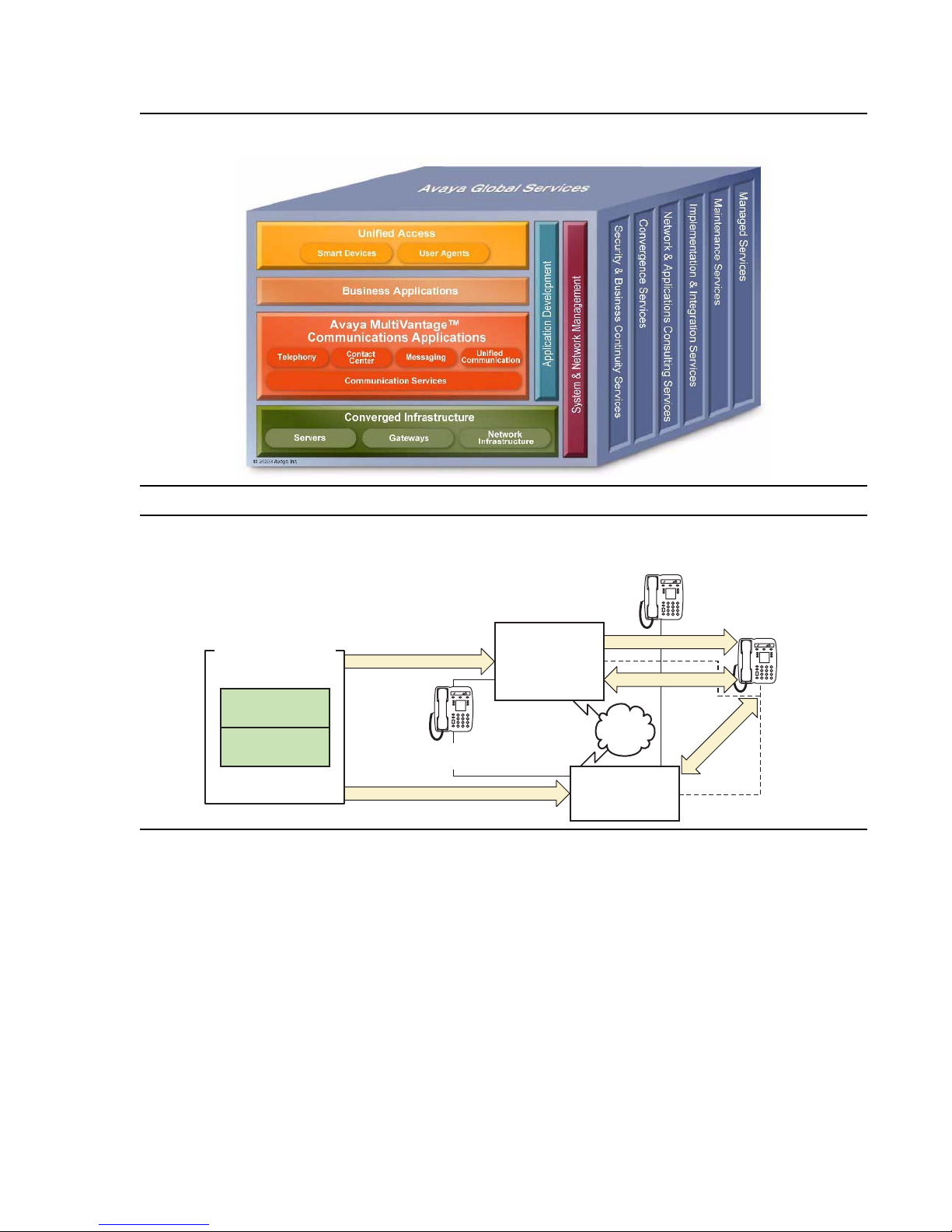
Avaya Application Solutions
Figure 1: Avaya Application Solutions
Figure 2: Communication Manager traffic flow
Telephone
IP
Communications
Device
RTP Audio
Avaya Media Servers
Communications
Applications
Communications
Manager
CCMS Signaling over IP
Circuit-switched
Telephone
H.248 Signaling
Avaya Media
Gateways
G650
MCC1
SCC1
H.323 Signaling
RTP Audio
PSTN
Avaya G700
Communication Manager is the next generation of Avaya call processing software.
Communication Manager is an open, scalable, highly reliable, and secure telephony
application. Communication Manager operates on Avaya Media Servers, and on the existing
family of DEFINITY servers.
Communication Manager carries forward all the current DEFINITY capabilities, plus all the
enhancements that enable enterprises to take advantage of new, distributed technologies ,
increased scalability, and redundancy. Communicati on Manager is evolved from DEFINITY
software and delivers no-compromi se, enterprise IP Telephony.
24 Avaya Application Solutions IP Telephony Deployment Guide
Page 25

Avaya Media Gateways support voice traffic and signaling traffic that is routed between
circuit-switched networks and packet-switched networks. The Gateways support all the
applications and adjuncts that can be used wit h the Avaya DEFINITY Enterprise
Communications Servers (DEFINITY ECS). These Gateways work with standards- based data
networks and easily connect with the Public Switched Telephone Network (PSTN).
Communication Manager is extensible to IP, digital and analog telephones, and wireless
business solutions. Avaya Communication Devices work with the full feature set of
Communication Manager to help enterprises be more productive by providing anytime,
anywhere access to maximize business continuit y.
Avaya Communication Manager
Avaya Communication Manager provides use r and system management functi onality , intelligent
call routing, applic ation integration and e xtensibility, and enterprise communications network ing.
Communication Manager operates on Avaya Media Servers, and on the existing family of
DEFINITY servers. For more information on the A v aya Applica tion Solu ti ons re lated feat ures of
Communication Manager, see Call processing
.
Avaya Communication Manager
The following additional resource provides even more details on Communication Manager:
www.avaya.com/
Avaya Media Servers
An Avaya Media Server provides centralized, enterprise-class call proces sing. This call
processing can be distributed across a multi-protocol network (including IP) to support a highly
diversified network ar chitect ure that consi st s of headq uarters , branch, remote, small, an d home
offices.
Linux-based servers
The Avaya S8300, S8500 and S8700-series are Linux-based Media Servers. These servers
support:
● Distributed IP Networking and centralized call processing acr o ss multi-service networks
● Dual server design with hot fail-over
● Redundant LAN Interfaces and remote survivable call processing
For more information on the architecture and the functionality of the Media Servers, see:
● Hardware Guide for Avaya Communications Manager
Issue 3.4.1 June 2005 25
Page 26

Avaya Application Solutions
Note:
Note: For US Business Partners: https://www.avaya.com/doc/gpp/public/pss/category/
cs/eclips/media_servers_gateways/index.html
Avaya DEFINITY Servers
Avaya Communication Manager also runs on the fo llowing DEFINITY Servers, which can be
IP-enabled:
● Avaya DEFINTY Server R
● Avaya DEFINITY Server SI
● Avaya DEFINITY Server CSI
These servers run on the Oryx/Pecos proprietary operating system, and function in the same
way as the Media Servers in Figur e 2: Communication Manager traffic flow
servers fit into Avaya CMC1, SCC1, and MCC1 Media Gateways.
The focus of this document is network design incorporating the newer Communication Manager
platforms. Therefore, the DEFINITY Servers are only discussed briefly here. For detailed
discussions on Communication Manager supported by these DEFINITY Servers, see:
on page 24. These
● For US Business Partners: https://www.avaya.com/doc/gpp/public/pss/category/cs/eclips/
definity_servers/index.html
Avaya Media Gateways
An Avaya Media Gateway supports bot h bearer traffic and signaling traffi c that is routed
between packet-switched networks and circuit-switched networks. Communication Manager
running on Avaya Media Servers controls voice and signaling over a variety of stackable and
modular Media Gateways:
● Avaya G150 Media Gateway
● Avaya G250 Media Gateway
● Avaya G350 Media Gateway
● Avaya G650 Media Gateway
● Avaya G700 Media Gateway
● Avaya CMC1 Media Gateway
● Avaya SCC1 Media Gateway
● Avaya MCC1 Media Gateway
● MultiTech MultiVoIP Gateway
26 Avaya Application Solutions IP Telephony Deployment Guide
Page 27

The Media Gateways contain the network and the endpoint interfaces, as well as call
classification, announcement boards, and so on. Through these interfaces, Communication
Manager performs gateway/gatekeeper fu nctions. For more information on the Media
Gateways, see Call processing
.
The following additional resources provide even more details on the Avaya Media Gateways:
For US Business Partners: https://www.avaya.com/doc/gpp/public/pss/category/cs/eclips/
media_servers_gateways/index.html
Avaya Integrated Management
Avaya Integrated Management is systems-ma nagement software for managing converged
voice and data networks. The applications include network management, fault management,
performance management, configuration management, and policy management functionality.
The Avaya Integrated Management applicat ions include:
● Avaya Site Administration
● Avaya MultiSite Administration
Avaya Communication Manager
● Avaya Fault and Performance Manager
● Avaya Proxy Agent
● Avaya Voice Announcement Manager
● Avaya VoIP Monitoring Manager
● Avaya Network Management Console and System View
● Avaya Address Manager
● Avaya Network Configuration Manager
● Avaya QoS Manager
● Avaya Secure Access Administration
● Avaya SMON Manager
● Avaya Software Update Manager
● Avaya VLAN Manager
● Avaya Provisioning and Installat ion Manager
● Avaya Device Managers
For more information on Avaya Integrated Management, see:
● Avaya Integrated Management on page 215
● For US Business Partners: https://www.avaya.com/doc/gpp/public/pss/category/
system_network_management.html
Issue 3.4.1 June 2005 27
Page 28

Avaya Application Solutions
Avaya communication devices
Avaya Communication Manager provides intelligent control for thes e smart devices:
● Avaya IP Telephones: 4600 Series (4602, 4606, 4612, 4620, 4624, 4630)
● Avaya digital telephones: 6400 Series, 2402, and 2420
● Avaya analog telephone (6200 Series, 2500, and 2554)
● Avaya IP Softphone
● Avaya IP Softphone for Pocket PC
● Avaya IP Agent
● Extension to Cellular Application
● DEFINITY Wireless DECT System
● Avaya Wireless Telephone Solutions
For more information about Avaya smart devices, see:
● Wireless on page 138
● For US Business Partners: https://www.avaya.com/doc/gpp/public/pss/category/
telephone_end_user_devices.html
Avaya Communication Manager applications
Avaya Communication Manager has embedded capabilities for:
● Call Center
● Compact Call Center
● Computer Telephony Integration (CTI)
● Messaging
● Conferencing systems
● Unified Communication Center
These applications are briefly discussed in Communication applications on page 103.
28 Avaya Application Solutions IP Telephony Deployment Guide
Page 29

Call Center
The Avaya Call Center solution is bui lt on proven and innovative automatic call distribution
(ACD) technology. This technology offers a suite of call routing capabilities that help agents
handle calls more effectively . Customers can select from a powerful assortment of features,
capabilities, and applications that are specially designed to enhance call center operat ions:
● Agent Access
● Avaya Call Management System
● Avaya Call Management System Supervisor
● Avaya Basic Call Management System
● Avaya Business Advocate
● Call Center
- Avaya Call Center Basic
- Avaya Call Center Deluxe
- Avaya Call Center Elite
Avaya Communication Manager
● Call Recording
● CALLMASTER® series digital telephones
● Computer Telephony (ASAI)
● Avaya Visual Vectors
● Avaya IP Agent
● Avaya Network Reporting
● Avaya Virtual Routing
Compact Call Center
● Basic Call Management
● Reporting Desktop
● Computer Telephony
For more information on these subjects, see:
US Business Partners: https://www.avaya.com/doc/gpp/public/pss/category/
call_center_crm.html
Issue 3.4.1 June 2005 29
Page 30

Avaya Application Solutions
Computer Tel ephony Integr ation (CTI)
CTI opens up Application Pr ogrammer Interfaces, which can be used to control the server from
an external application. For more information on CTI, see:
US Business Partners: https://www.avaya.com/doc/gpp/public/pss/category/
call_center_crm.html
Messaging
The following messaging systems are supported by Avaya Communication Manager:
● INTUITY™ Messaging Systems
● Aria® Messaging Systems
● Serenade® Messaging Systems
● Modular Messaging®
For more information on Avaya messaging products, see:
● For US Business Partners: https://www.avaya.com/doc/gpp/public/pss/category/
messaging.html
Conferencing systems
For more information on Conferencing, see:
● For US Business Partners: https://www.avaya.com/doc/gpp/public/pss/category/
conferencing.html
Unified Communication Center
For more information on the Unified Communication Center (UCC), see:
● For US Business Partners: https://www.avaya.com/doc/gpp/public/pss/category/
unified_communication.html
30 Avaya Application Solutions IP Telephony Deployment Guide
Page 31
Avaya Application Solutions platforms
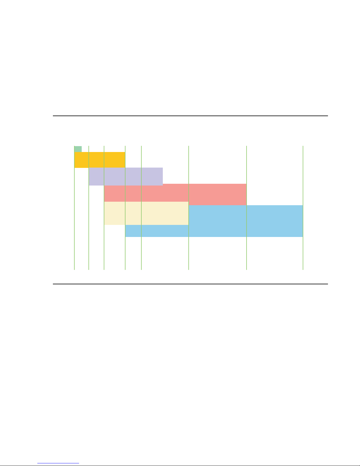
The Avaya Communication Manager port fol io covers smal l, medium, a nd la rge e nterp rises with
advanced communications needs between 2 and 36,000 stations per system. This chapter
provides an overview of the Avaya Communication Manager platforms architecture that
supports Avaya Application Solutions components and features.
Figure 3: Avaya Application Solutions platforms
40 200 500 900 5K 16K 36K2
G150
S8300/G700/
G350
S8500/G650/
G700/G350 IP-Connect
S87xx/G650/
G700/G350 IP-Connect
S87xx/G700/G350
S87xx/SCC1/MCC1/G700/G350
Mulit-Connect
cynd103c KLC 10/25/04
Issue 3.4.1 June 2005 31
Page 32

Avaya Application Solutions platforms
Table 1: Avaya Application Solutions comparison matrix contains an overview of the different
Avaya Media Servers that are discussed in this chapter.
Table 1: Avaya Application Solutions comparison mat rix
Operating
system
Processor
General
Business
analog
equivalent
BHCC rate
Avaya
S8300
Media
Server
Pre-2.0 —
Linux
(Redhat
v6.2)
2.0 — Linux
Avaya S8500
Media Server
Linux
(Redhat v8.0)
Avaya S8700
Media Server
IP-Connect
Solution
Pre-2.0 —
Linux (Redhat
v6.2)
2.0 — Linux
(Redhat v8.0)
Avaya S8700
Media Server
Multi-Connect
Solution
Pre-2.0 —
Linux (Redhat
v6.2)
2.0 — Linux
(Redhat v8.0)
(Redhat
v8.0)
Intel Pentium
class server
20-GB hard
disk drive
256 MB of
RAM
Intel Pentium
Class Server
20-GB hard
disk drive
256 MB of
RAM
Removable
Flash card
backup
Intel Pentium
Class Server
20-GB hard
disk drive
256 MB of
RAM
Removable
Flash card
backup
Intel Pentium
Class Server
20-GB hard
disk drive
256 MB of
RAM
Removable
Flash card
backup
Up to 10,000 Up to 100,000 Up to 100,000 Up to 300,000
Media
Gateways
G700 or
G350: up to
50
G650: up to
64
G700 or
G350: up to
250
32 Avaya Application Solutions IP Telephony Deployment Guide
G650: up to
64
G700 or
G350: up to
250
MCC1: up to
64
SCC1: up to
64
G700 or G350:
up to 250
1 of 2
Page 33

Small to mid-size enterprise
Table 1: Avaya Application Solutions compari son mat rix (continued)
Number of IP
endpoints
supported
Reliability /
survivability
Avaya
S8300
Media
Server
Up to 450 Up to 12,000 Up to 12,000 Up to 12,000
Local Spare
Processor
Avaya S8500
Media Server
No options Duplicated
Avaya S8700
Media Server
IP-Connect
Solution
Processor
Local Spare
Processor
backup for
G700 or
G350
Avaya S8700
Media Server
Multi-Connect
Solution
Duplicated
Processor
Duplicated
control
network
connection
Duplicated
bearer
connectivity
Local Spare
Processor
backup for
G700 or G350
2 of 2
Small to mid-size enterprise
Avaya S8300 Media Server and Avaya G700
or G350 Media Gateway
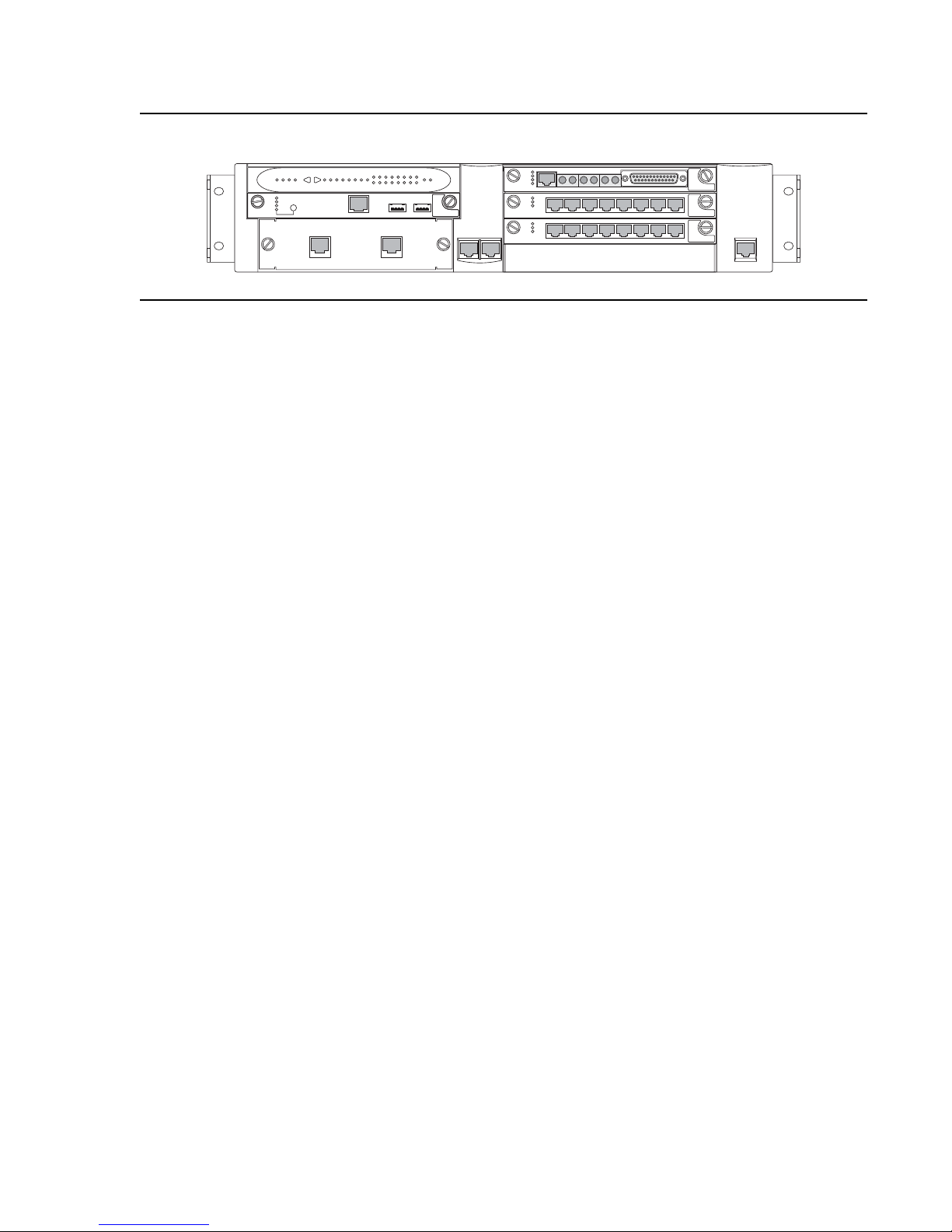
The S8300 Media Server and G700 Media Gateway solution (Figure 4: Avaya G700 Media
Gateway with the S8300 Media Server on page 34) seamlessly deli vers voice, fax, and
messaging capabilities over an IP network. This unique solution converges the power of the
Avaya Communication Manager feature set with the power of distributed Ethernet switching
from the P330 Stackable Switching System.
Issue 3.4.1 June 2005 33
Page 34
Avaya Application Solutions platforms
Figure 4: Avaya G700 Media Gateway with the S8300 Media Server
ALM PWR
V1
ALM
TST
ACT
OKTO
REMOVE
LNK COL Tx Rx FDX FC Hspd LAG EXT1
CPUMSTR
SHUTDOWN
51 52 53 54 55 56 57 58
59 60 61 62 63 64 65 66
SERVICES USB1 USB 2
EXT2
V2
V3
V4
EXT 1 EXT2 CONSOLE
EISO EMSM EOSI
ALM
TST
ACT
SIG
E1/T1 EIA 530A DCE
ALM
TST
ACT
123456 87
ALM
TST
ACT
123456 87
msdcs83b KLC 031402
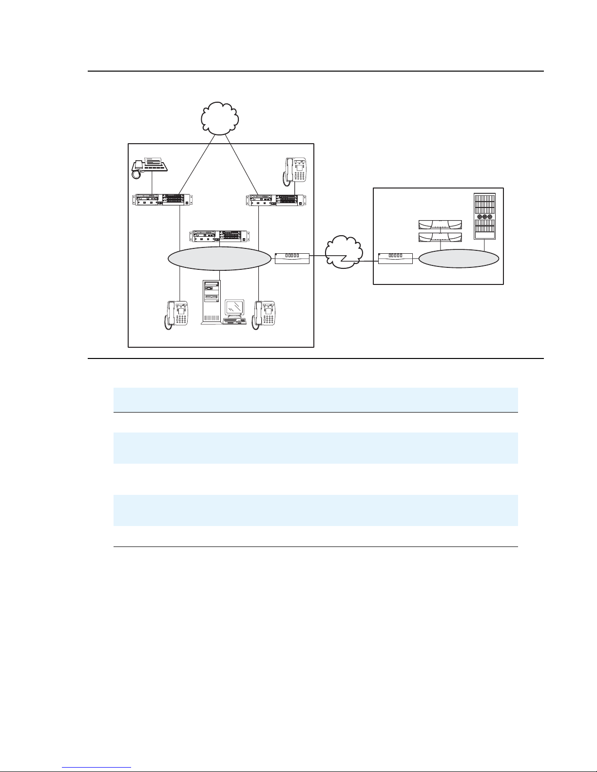
The S8300 / G700 or G350 is an stand-alone solution with a capacity of up to 450 IP and non-IP
endpoints. A Linux-based S8300 Media Server can support up to 50 G700 or G350 Media
Gateways. An S8300 Media Server and G700 or G350 Media Gateway solution comprises:
● A G700 or G350 Media Gateway. A G700 or G350 Med ia Gateway is always require d. The
G700 or G350 hosts an S8300 Media Server and various media modules depending on
the telephony needs at a particular location.
● The S8300 Media Server . The S83 00 Medi a Server is i nserted in to a media modul e slot . If
present, the S8300 supports the Communication Manager that provides call-processing
capabilities and features for the system. The S8300 can be configured as the primary call
controller or as a Local Survivable Processor (LSP) standby server for another S8300
Media Server in the configuration.
Multiple G700 Media Gateways can be connected to each other through an Octaplane 8-Gbps
stacking fabric, and Avaya P330 Expansion Modules, which allows adding additional Ethernet
ports, fiber interfaces, ATM acces s or WAN access modules without additional switches. The
system can be networked to other PBXs and Communi cation Manager platforms through an IP
network.
Some of the key characteristics of this pl atform are
● Expert System Diagnostic Capability
● Hot-swappable Media Modules
● Co-resident INTUITY AUDIX messaging.
The platform is scalable, and has surv ivability and redundancy capability through a Local
Survivable Processor (LSP), which supports all of the features of Communication Manager.
34 Avaya Application Solutions IP Telephony Deployment Guide
Page 35
Small to mid-size enterprise
ALM
TST
ACT
ALM
TST
ACT
ALM
TST
ACT
OKTO
SERVICES
USB1
USB2
EIA 530A DCE
ALM
TST
ACT
SIG
ALM
TST
A
CT
ALM
TST
ACT
REMOVE
ALM
TST
A
CT
OKTO
USB1
USB2
ALM
TST
ACT
SIG
ALM
TST
ACT
ALM
TST
ACT
REMOVE
ALM
TST
ACT
OKTO
SHUTDOWN
SERVICES
USB1
USB2
E1/T1
EIA 530A DCE
ALM
T
ST
ACT
SIG
Figure 5: Avaya S8300/G700 or G350 in a stand-alone configuration
Stand alone Office
PSTN
with IPTrunk link
to Avaya PBXs
ALM
TST
ACT
SIG
ALM
ALM
TST
TST
ACT
ACT
SHUTDOWN
OKTO
REMOVE
USB1
USB2
SERVICES
ALM
TST
ACT
G700/G350
EISO EMSM EOSI
E1/T1 EIA 530A DCE
1 2 3 4 5 6 87
1 2 3 4 5 6 87
ISDN-PRIISDN-PRI
G700/G350
with S8300/ICC
ALM
TST
ACT
OKTO
REMOVE
EISOSOEMSM EOSI
ALM
TST
ACT
SIG
E1/T1
EIA 530A DCE
ALM
TST
ACT
SHUTDOWN
SERVICES
USB1
USB2
1 2 3 4 5 6 87
ALM
TST
ACT
1 2 3 4 5 6 87
ALM
TST
ACT
SHUTDOWN
OKTO
REMOVE
EISO EMSM EOSI
ALM
TST
ACT
SIG
E1/T1 EIA 530A DCE
ALM
TST
ACT
USB2
SERVICES USB1
1 2 3 4 5 6 87
ALM
TST
ACT
1 2 3 4 5 6 87
G700/G350
DCPFax
IP WAN
IP
Phone
PC
IP
Phone
Edge
Router
IP TIE Trunk
Edge
Router
Table 2: Capacity limits for S8300
Feature Capacity
Avaya IP PBX
( S8300, S8700)
Ethernet (LAN)Ethernet
cynds110 LAO 101104
General Business Busy Hour Call Completion Up to 10,000
Number of IP users (cannot be combined with
Up to 450
non-IP Users)
Number of non-IP users (cannot be combined
Up to 450
with IP User s)
Number of trunks (independent of the number of
users)
Up to 450 (up to 100 SIP
trunks)
Total number of ports Up to 900
Issue 3.4.1 June 2005 35
Page 36

Avaya Application Solutions platforms
Table 3: Scalability for S8300
Feature Capacity
Number of G700/G350 Media
Gateways
Number of LSPs per server Up to 10
Minimum ratio of LSPs to
server
G700 hardware architecture
The design of the Media Gateway motherboard hardware brings together a multitude of
hardware functions into a single 2U 19-inch rack-mountable enclosure. Integrated on the
motherboard are:
● A gateway function that bridges the IP and telephony domains
● An Ethernet switching function and associated management features through an
integrated Layer 2 switch architecture
● Processing elements that are necessary to support traditional telephony interfaces, such
as trunks and analog/DCP lines
These processing elements are controlled by Communication Manager, thus offering the
complete set of Communication Manager call feat ures to both I P users and trad itional telephony
users.
Up to 50
1:50
From a hardware perspective, the G700 Media Gateway is an enclosure with an internal power
supply and a motherboard. This design that provides the hardware resources for the Gateway
functions, and electrical connectivity for four media modules, one Cascade module, and one
Expansion module. Designed to resemble the P330, the enclosure houses the power supply
and the motherboard, and provides the physical support to allow the insertion of the various
modules. Figure 6: Avaya G700 Media Gateway (front view)
on page 37 shows the Media
Gateway enclosure.
36 Avaya Application Solutions IP Telephony Deployment Guide
Page 37
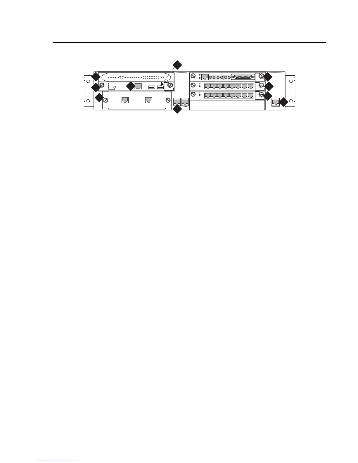
Figure 6: Avaya G700 Media Gateway (front view)
4
ALM
TST
ACT
SIG
ALM
TST
ACT
ALM
TST
ACT
Figure notes:
1
ALM
TST
ACT
SHUTDOWN
OKTO
2
REMOVE
3
SERVICES USB1 USB 2
5
6
EISO EMSM EOSI
E1/T1 EIA 530A DCE
123456 87
123456 87
Small to mid-size enterprise
7
7
7
8
cynds111 KLC 121003
1. LED board
2. S8300 Media Server
3. Services port
4. USB ports
5. Avaya P330 Expansion Module
6. 10/1 00 B ase T Ether ne t ports
7. Media Modules
8. Serial (“Console”) connector
The four media module slots can be populated with any combination of medi a module types:
● T1/E1 with integrated CSU/DSU (MM710)
● 8-port analog line/trunk (MM711)
● 8-port DCP line (MM712)
● 8-port BRI trunk (MM720)
● VoIP Engine (MM760)
● Internal Communications Controller (ICC-only 1 per gateway; must be in the first slot)
The Cascade module comes from the Converged I nfrastructur e LAN Switches product line, an d
provides the Octaplane interface:
● One full-duplex 4-Gbps Ethernet port (8 Gbps bandwidth) for high-speed interconnection
of up to 10 media gateways and P330 data switches in a stack arrangement
● Expansion module interface allows the use of expansion modules in the gateway. These
expansion modules also allow WAN access routing.
The G700 motherboard hardware design involves three major blocks:
● A DSP engine and associated packet processor complex. This complex performs IP/UDP/
RTP processing, echo cancellation, G.711 A/µ, G.729 (with or without silence
suppression), fax relay, silence suppression, jitter buffe r management, packet loss
concealment, and so on.
● A Gateway Processor complex. This complex is the master controller of the Gateway, and
controls all resources inside the Gateway under the direction of the Gateway Controller.
Examples of the functions implemented here include the Media Module Manager, Tone/
Clock, PKTINT, Announcements (record/playback), and H.248 signaling to the Gateway
Controller.
Issue 3.4.1 June 2005 37
Page 38

Avaya Application Solutions platforms
● An Intel 960 processor complex. This complex is based on the architecture of the P330
data switch. This complex provides an eight-port Layer 2 switch function, and the i960
manages the Expansion and Cascade modules.
These major blocks are interconnected through two major communication paths: an Ethernet
link and the Time Divi sion Multiplexed (TDM) bus similar to that in a port network. In additi on,
the motherboard provides electrical and physical connectivity for four media modules.
VoIP Engine complex
The internal VoIP Engine block is where PCM voice samples are encoded and put into IP
packets, and vice-ver sa. This block implements all the functions that are normally associ ated
with a Gateway. Such functions include packet loss concealment, jitter buf fer management, and
transcoding.
The VoIP Engine of the G700 motherboard has three major components: two Digital Signal
Processors (DSPs), and a Motorola MPC8260 processor. The DSPs together provide the same
VoIP channel capacities as the TN2302 Prowler circuit p a ck: 64 G.711 channels or 32 G.729
channels.
Each additional VoIP Media Module (MM760) increases the VoIP channel capacity of a G700
media gateway by the equivalent of a TN2302 circuit pack.
The G700 Media Gateway Processor
The G700 Media Gateway Processor (MGP) is the master controlle r of the Media Gateway. The
Motorola 860T processor in this complex implements the H.248 protocol to communicate with
the Gateway Controller. Under the direction of the Gateway Controller, the 860T Gateway
Processor controls the flow of data through the Gateway . The 860T processor communicates
with other processors in the system – the VoIP Engine processor, the i960 processor, and any
processors on media modules – through either the control channel of the TDM bus, or an
Ethernet link (the i960 processo r connects only through Ethernet).
Functions implemented within the MGP complex include:
● Management of the media modules (reset control, board and interface insertion, and so on)
● Termination of the LAPD protocol running on the D-channel of E1/T1 trunks and BRI lines
and trunks (32 channels capacity).
● Recorded announcement playback (15 playback channels, 1 record channel)
● Tone detection and generation (15 ports of tone detection)
● System clock generation and synchronization to an external network ti ming reference
● Download agent for the media modules
● License/translation storage
● System maintenance
● H.248 signaling
● Connection management
38 Avaya Application Solutions IP Telephony Deployment Guide
Page 39

Small to mid-size enterprise
Avaya IA770 INTUITY AUDIX Messaging Option for S8300/G700
The Avaya IA770 INTUITY AUDIX Messaging Application, (I A7 70), is optionally embedded on
the S8300 Media Server installed in a G700. The IA770 delivers voice and e-mail to enhance
and simplify the communicat ions and t he exchange of infor mation wit hin both smal l enterpr ises,
and the smaller locations of large enterprises. The IA770 uses the Linux operating system,
which is consistent with the operating system of the Media Gateway.
The IA770 supports INTUITY digital (TCP/IP) and AMIS networking protocols. More extensi ve
networking can be provided with the Avaya Interchange.
The IA770 consists of license-f il e-activated software that resides on the S8300 Serv er. For
Communication Manager releases before 2.2, IA770 is implement ed on an S8300 daughter
card. For Communication Manager 2. 2 an d later, new installations implement IA770 Embedded
Messaging H.323 integration on the S8300 without the daughter card.
Voice Announcement over the LAN
Voi ce Announcement over the LAN ( V AL) capabili ties are co-reside nt on the A vaya G700 Media
Gateway. This G700 VAL announcement capability allows backup and restore of
announcements to an external PC or a file server on the customer’s local area network (LAN),
in addition to internal backup in Flash memory. The announcements are stored as
industry-standard wavefo rm (.wav) files. This enables customers to create high-quality, studio
announcements, save the announcements to their PC or server, and then share the same
announcements with multiple Avaya Application Solutions. Other features of the G700 VAL
announcement offer include:
● A G700 VAL announcement source functions the same as the TN2501AP for
administration, recording, file handling using FTP, playback, and measurements.
● Each G700 VAL announcement source used is counted as a VAL boar d towards the
Maximum VAL boards on the customer-options screen. The S8300 Media Server now
comes with a license entitlement for using up to 50 VAL circuit packs. The S8700 Media
Server comes with a license entitlement for one, and requires the purchase of additional
licenses to enable the maximum of 50 which applies to both TN2501AP and G700 VAL
sources.
● Voice quality is impacted when played over IP. However, qual ity is acceptable even with 2
hops and 10-msec delay.
● The use of G700 VAL sourced announcements impacts that gateway’s ov erall occupancy,
and IP Telephony resources (for example, high use global announcements such as the
main greeting and some VOAs) should be handled by TN2501 circuit packs if the agents
are not homed to that G700.
● FTP access for the G700 announcements use the same IP address as the address that is
assigned to the G700 when installed (this address is displayed on the Media-Gateway
form)
Issue 3.4.1 June 2005 39
Page 40

Avaya Application Solutions platforms
S8300 primary controller architecture
The S8300 Media Server has the same form factor as the Avay a media modules. The S8300 is
installed in slot V1 of the G700 or G350 Media Gateway. The S8300 can be configured as either
a primary controller (a.k.a. “ICC”) or as a local survivable processor (LSP).
Configured as a primary controller, the S8300 provides Communication Manager call control.
The controller targets the small-line-size, cost-consci ous portion of the market, and as such,
must be cost competitive with other solutions. The controller is based on standard Intel IA32
architecture, and runs the industry-standard Linux operating system.
The S8300 runs the following co-resident appl ications:
● H.248 Media Gateway Controller
● H.323 GateKeeper
● Communication Manager Feature Server
● INTUITY AUDIX Messaging system (installed in the G700)
The S8300 primary controller, when installed in the G700, can be ordered both with and without
INTUITY AUDIX support.
The S8300 faceplate provides connectivit y for two USB devices, and an Ethernet port for
technician access. The faceplate als o has operational LEDs and a shutdown swit ch. The media
module backplane connector provides the interfaces for the internal 10/100 Ethernet bus and
the TDM Bus.
An S8300 primary controller can control up to 50 G700 or G350 Media Gateways, 450 st at ions,
and 450 trunks.
S8300 as the Local Survivable Processor (LSP)
The LSP is an S8300 Media Server installed in a G700 or G350 Media Gateway. The LSP
provides survivability when the primary controller, either an S8300 ICC or an S8700 External
Communications Controller (ECC), is ina ccessibl e. Each syst em can hav e multipl e LSPs. Each
LSP has a copy of the primary controller’s translations. The tran slations are updated regularly
from the primary controller b way of a virtual link through an IP network. Typically, all LSPs are
in idle mode, where the LSPs are not processing any calls. When the Media Gateway's
Processor (MGP) or individual IP endpoints perceive the primary controll er to be unreachable,
the MGP or the IP endpoints attempt to register with an LSP. The LSP does not actively take
over when the primary controller becomes unreachable, but wait s for MGPs and IP endpoint s to
register with it. Each LSP runs in license-no rmal mode until IP Telephones or MGPs register
with it, which triggers the LSP to move into a license-error mode. Each LSP can run in active
mode for a maximum of 10 days per outage before it must be reset manually. A “reset 3”
command on the LSP forces devices registered with it to return to their prim ary controller. When
the customer resets the LSP, the 10-day license timer is reset after it contacts the primary
controller.
40 Avaya Application Solutions IP Telephony Deployment Guide
Page 41
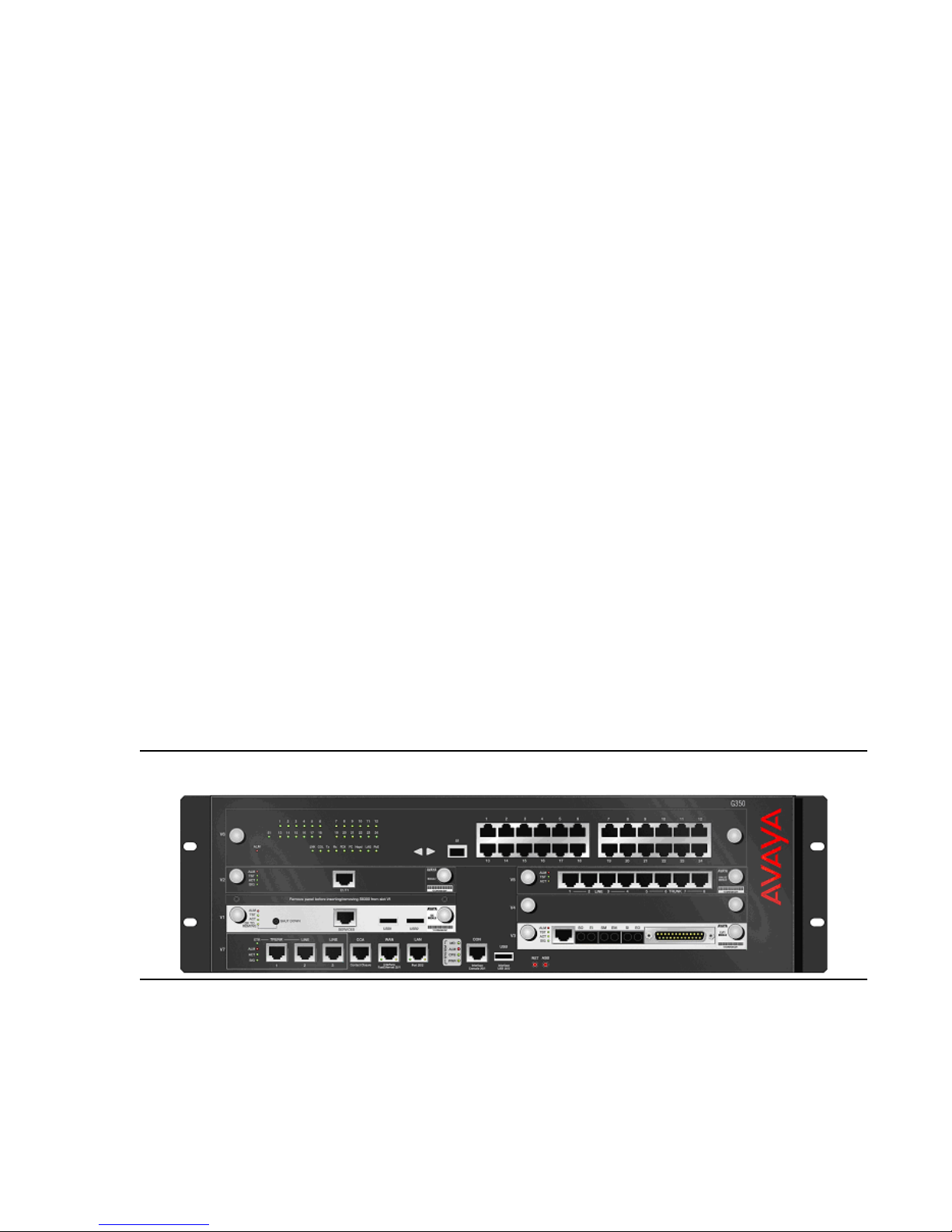
G350 Media Gateway
The Avaya G350 Media Gateway is a standalone converged networking device that provides
the following voice and data networking services:
● Voice over IP Media Gateway based on H.248 protocol
● WAN (data) connectivity and routing
● Power-over-Ethernet LAN switching
● Telephone exchange for legacy telephones and trunks
● Survivability features for continuous voice services
● A built-in protocol analyzer capable of exporting files in libpcap format for analysis by
Ethereal and tcpdump,
● MD5 authentication for OSPF,
● Support for GRE tunnels,
● Policy-based routing support,
● Support for SNMPv3,
Small to mid-size enterprise
● Support for SSH and SCP for secure administration and upgrading,
● A new fair-voice-queue for enhanced QoS support for IP Telephony application,
● Support for DSL modems as either primary or backup links.
In addition, the G350 now supports enhanced management features including USB modem
support and LSP alarming. The USB modem interface is intended for administr ation only. As
such, it is not routable, and cannot be used as a backup li nk in the event of a network failure.
Furthermore, the G350 will send SNMP traps to its active call server. Should the G350 fail over
to an LSP, the G350 will send alarms directly to the new call server with no need for manual
configuration.
Figure 7: G350 Media Gateway
The G350 is designed to meet the needs of a small branch off ice of a large enterprise , providing
all infrastructure needs in one box. G350 is optimized for use in a 16-24 user environment.
Issue 3.4.1 June 2005 41
Page 42

Avaya Application Solutions platforms
The G350’s internal rout er enables you to connect directly to an outside WAN, without needing
additional routing equi pment.
The G350 provides telephone services thr ough an Avaya media ser ver , s uch as the S8300. The
media server controls the routing of voice traffic through the G350. The media server can be
either internal (S8300) or external (S8700, S8500, or S8300). The media server runs Avaya
Communication Manager software.
Pluggable media modules provide interfaces for many types of telephones and trunks. This
allows you to incorporate legacy end point devices such as analog and digital telephones.
The G350 can be managed through the Avaya G350 Command Line Interface, the G350
Device Manager graphic user interface, or the centralized Avaya Integrated Management
application.
G350 Configurations
The G350 is a modular device with mult iple conf iguration possibil ities t o meet specific i ndividual
needs. Six slots in the G350 chassis house various media modules, providing connections for
different telephones, telephone trunks, data devices, and data lines.
Media server configuration options for the G350 include:
● Standalone. In this c onfigur ation, one media modul e slot house s the S8300 i nternal Media
Server, which runs the call control applications for the G350. The remaining slots house a
customized selection of medi a modules, which con nect to ci rcuit -switc hed phon es, tr unks,
and data devices. This configuration is capable of supporting up to 40 stations (maximum
of 26 legacy Analog/DCP stations) and 35 trunks, including both circuit-switched and
IP-switched endpoints.
● Media Gateway. In this configuration, there is no internal media server. The G350 is
dependent on a separate controller. This may be an external standalone media server
such as the S8500 or S8700 or the S8300 housed in a separate media gateway. All six
media module slots are available to house a customized selection of media modules.
● Survivable. In this configuration, an external media server provides primary controlling
service to the G350. The S8300 populates one of the module slots as a backup control ler
and functions in Local Survivable Processor (LSP) mode. If the external media server
stops serving the G350, the S8300 t akes over the service. As for st andalone configurat ion,
the remaining slots house a customized selection of media modules.
Each G350 should deploy as a single unit at a remote location. Multiple G350s may be
deployed in many remote branches of a large organization. Large branches or main offices
requiring more capacity than a single G350 shoul d deploy one or more Avaya G700 Media
Gateways. In addition to media gateway functions similar to those of G700, the G350 can
optionally provide integrated power-over-Ethernet and WAN routing functions through media
modules.
The G350 now supports up to 10 concurrent call center agents. Customers requiring more call
center agents in a small branch office should consider the G700 media gateway.
42 Avaya Application Solutions IP Telephony Deployment Guide
Page 43
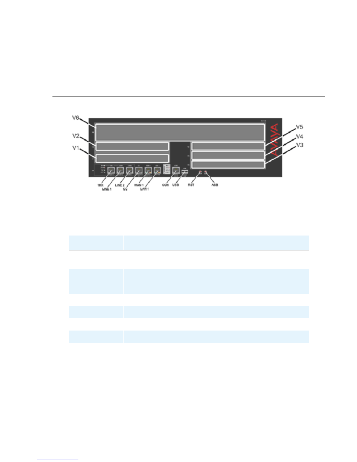
G350 Specifications
The G350 chassis features six media module slots (V1 to V6) and various fixed ports and
buttons. V1 to V5 are G700 form factor media module slots cap able of housing existing G700
media modules. V6 is a high-density media module (HDMM) slot for housing new high cap aci ty
media modules (see below).
Figure 8: G350 chassis
Small to mid-size enterprise
The following tables describe the functions of the fixed ports and buttons on the G350 front
panel.
Table 4: Fixed ports on the G350 front panel
Port Description
TRK An analog trunk port. Part of an integrated analog media
module.
LINE 1, LINE2 Analog telephone port s of t he integrat ed analog medi a module.
An analog relay between TRK and LINE 1 provides Emergency
Transfer Relay (ETR) feature. {ETR could be confusing term}
CC RJ-45 port for ACS (308) contact closure adjunct box.
WAN 1 RJ-45 10/100 Base TX Ethernet port.
LAN 1 RJ-45 Ethernet LAN switch port.
CON Console port for direct connection of CLI console.
USB USB port, not supported in this release.
Issue 3.4.1 June 2005 43
Page 44

Avaya Application Solutions platforms
Table 5: Buttons on the G350 front panel
Button Description
RST Reset button. Resets chassis configuration.
ASB Alternate Software Bank button. Reboots the G350 with the
software image in the non-defaul t bank.
Table 6: Supported media modules
Media module Description
MM312 (HDMM) 24 DCP telephone ports
MM314 (HDMM) 24 10/100 Ethernet ports with Power over Ethernet
MM340 1 E1/T1 WAN port
MM342 1 V.35/X.21 Universal Serial port (USP) WAN port
MM710 1 T1/E1 trunk port
MM711 8 universal analog ports
MM712 8 DCP telephone ports
MM714 4 analog telephone ports and 4 analog trunk ports
MM717 24 port DCP Media Module for G350/G700
MM720 8 ISDN BRI trunk ports
MM722 2 ISDN BRI trunk ports
S8300 Media server (LSP)
The MM710, MM711, MM712, and MM720 are existing G700 media modules.
Table 7: Additional G350 functions and capacities
Function Capacity
VoIP DSP engine 32 G.711 or 16 G.729 channels
Touch Tone Recognition
15 channels
(TTR)
Announcement 6 playback, 1 record
Number of stations 40 (18 analog)
44 Avaya Application Solutions IP Telephony Deployment Guide
1 of 2
Page 45

Small to mid-size enterprise
Table 7: Additional G350 functions and capacities (continued)
Function Capacity
Number of trunks (1 T1/E1) 40 (15 IP, 17 analog)
G700 form factor MMs no more than three
MM710 no more than one
MM717 or MM712
(possibly with MM312)
MM711 and/or MM714 no more than two
WAN modules (MM340
and MM342)
no more than one
no more than two
DEFINITY Server CSI and CMC1 Media Gateway
The Avaya Communication Manager with an A vaya DEFINITY® Server CSI offer is targeted at
small to mid-size customers, or the satellite offices of large corporations who require
sophisticated applications. This solution supports 50 to 500 telephones. The small to mid-size
customer segment tends to be multi-site with 2 to10 locations. These customers are interested
in applications such as voice messaging, networki ng, shared voice mail, and small call center
applications. Satellite offices of large corporati ons tend to require t he same applications that are
used at their headquarters location.
2 of 2
DEFINITY Server SI
and SCC1 or MCC1 Media Gateway
This solution is ideal for locations with 250 to 1,000 employees. This solution can support up to
2,400 stations with a seamless migrati on to larger Avaya Media Servers. More information on
these two platforms is available on the Avaya Support web site.
Issue 3.4.1 June 2005 45
Page 46

Avaya Application Solutions platforms
Mid-market to large enterprise
S8500 Media Server
The Avaya S8500 Media Server Platf orm is a new simplex Linux-based server running A vaya
Communication Manager (CM) software that will replace the DEFINITY SI and S8100
processing platfor ms fo r small er sites and f or customers who do n ot requi re a dupli cated ser ver
complex.
The S8500 system supports the Avaya MCC1, SCC1, CMC1, and G650 Media Gateways. The
Avaya G700 and G350 Media Gateways are also supported, provided that there is a TCP/IP
connection between the media gateway and a C-LAN circuit pack located in a MCC1, SCC1,
CMC1, or G650 Media Gateway. The S8500 has the capacity to support up to 64 port networks.
Up to 3 MCC1 port networks can be directly connected. Even though the server capacity
supports up to 64 port networks, the first release supports up to 400 stations (80% IP).
The S8500 Media Server allows for a seamless migration from DEFINITY SI, CSI, R, and
S8100 platforms. However, the S8500 will not support traditional circuit-switched Center Stage
Switch or ATM Port Network Connectivity.
46 Avaya Application Solutions IP Telephony Deployment Guide
Page 47

S8500 capacities
Table 8: Capacities for S8500
Feature Capacity
General Business Busy Hour Call Completion Up to 100,000
Number of stations + trunks Up to 3200
Mid-market to large enterprise
Number of IP users
Up to 3200
(IP trunks + IP stations)
Number of trunks
Up to 800 (up to 800 SIP trunks)
(IP trunks and non-IP trunks)
Number of stations (IP and non-IP) Up to 2400
Total number of ports Up to 44,000
Number of IP users: G700 or G350 / Total IP
Up to 5,000/12,000
users
(cannot be combined with non-IP users)
Number of non-IP users: G700 or G350 / Total
Up to 5,000/36,000
users
(cannot be combined with IP users)
Table 9: Scalability for S8500
Feature Capacity
Number of MCC1 and SCC1 in
Up to 3
Direct-Connection Configuration
Number of G650 in IP-Connect
Up to 64
Configuration
Number of G700 or G350 Media
Gateways
Number of LSPs per server Up to 50
Number of G700 or G350 gateways per
LSP
Up to 250
Up to 50
Issue 3.4.1 June 2005 47
Page 48

Avaya Application Solutions platforms
S8700 Media Server Multi-Connect configuration
The Avaya S8700 series Media Server with an MCC1 or SCC1 Media Gateway is targeted at
Avaya’s largest customers. These customers are typically experiencing rapid growth, and
looking for ways to consolidate their network. These are customers who require high-end
applications such as DEFINITY Call Center Solut ions, CTI applications, Unified Messaging,
multimedia conferencing, and voice/data network integration, and are evolving to an
IP-intensive environment. This solution supports up to 36,000 telephones.
This solution is also targeted at smaller customers who made an investment in DEFINITY, and
are looking for a smooth transition into industry-standard processors that wil l enable expanded
communications capabilities.
This is a large-office solution with the Media Server in the headquarter locations, with optional
servers/gateways in the branch of fices . There is also t he option of dupli cated headquarte rs with
branch and remote offices. The Linux-based Media Servers support up to 36,000 stations,
12,000 of which can be IP, and 8,000 trunks, with the capacity limit of 300,000 General
Business call mix BHCC.
Table 10: Capacities for S8700 / MCC1 / SCC1 / G650 / G700 / G350 Multi-Connect
Feature Capacity
General Business Busy Hour Call
Completion
Up to 300,000 (analog equivalent)
Up to 100,000 (IP station to trunk
call)
Number of stations Up to 36,000
Number of IP users
Up to 12,000
(IP trunks + IP stations)
Number of trunks
Up to 8,000 (up to 1000 SIP trunks)
(independent of the number of users)
Total number of ports Up to 44,000
Number of IP users: G700 or G35 0 / Total IP
Up to 5,000/12,000
users
(cannot be combined with non-IP users)
Number of non-IP users: G700 or G350 /
Up to 5,000/36,000
Total users
(cannot be combined with IP users)
Because calls are processed through both IP and traditional circuit switch links, this plat form is
called the Multi-Connect Soluti on. The Media Server and the Gateways call control traffic is
over a private dedicated Ethernet network that is provided by Avaya. The inter-Port Network
TDM traffic flow is supported by a TDM-based Center Stage Switch (CSS), or an Asynchronous
Transfer Mode (ATM) switch.
48 Avaya Application Solutions IP Telephony Deployment Guide
Page 49

Mid-market to large enterprise
This solution is scalable to up to 44 Port Networks (PNs) through CSS configuration, and up to
64 PNs in an ATM configuration. The Multi-Connect solution has three reli ability options:
● Standard. S8700 series Media Server, with memory shadowing, two uninterruptible power
supplies (UPS), one switch, and one IPSI in each IPSI-connected PN
● High. Standard reli abili ty, plus a second switch and a second IPSI in each IPSI -c onnected
PN. This design provides for a second redundant call control network
● Critical. High reliability plus duplication of the bearer network
Table 11: Capacities for S8700 / MCC1 / SCC1 / G650 / G700 / G350
Multi-Connect
Feature Capacity
Number of G700/G350 Media Gateways Up to 250
Number of MCC1 / SCC1 Port Networks Up to 44 with CSS
Number of LSPs per server Up to 50
Number of G700/G350 Gateways per
LSP
1. The information in this table represents the maximum number of calls
the S8700 Media Server can execute when unconstrained by other
factors such as TDM bus lim it a tions, call duration, or a small numb er of
telephones. We assume pr ocesso r occup anc y of 0.90, at whic h vario us
delay criteria such as cut through is preserved, and is just at the
threshold where call shedding would commence.
S8700 series Media Server
The Avaya S8700 series Media Server always consists of two I n tel-based servers running on a
Linux operating system. In S8700 Multi-Connect and IP- C onnect configurations, the S8700
Media Server provides the main feature and management processing capabilities of the
system. The Media server is connected to other system and external components primarily
through IP networks.
1
64 with ATM
Up to 50
S8700 external features
● Six 10/100 Ethernet NICs per server, which are used as follows:
- Dual control network connections
- A heartbeat link to the duplicated server
- Administrative access from the corporate network
- Technician access
- One unused
Issue 3.4.1 June 2005 49
Page 50
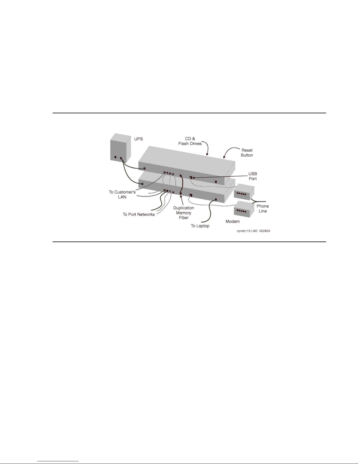
Avaya Application Solutions platforms
● A CD-ROM for on-site software loading
● A PCMCIA Flash disk for translations backup
● USB ports for remote access connections (modems and other auxiliary devic e s)
● A reset button
● Support for global power
● A fiber-channel interface to support server duplication
Figure 9: Avaya S8700 external features
UPS or power backup - The S8700 series Media Servers always require power backup to
avoid power problems, and to ensure graceful shut down of the syst em processes if the power
fails. The AS1 700-VA UPS provides approximately 30 minutes of power backup. Combinations
of battery extension modules and a 1500-VA UPS provide up to 8 hours of power backup.
The AS1 UPS units use SNMP traps to send an alarm when power fails. This action initiat es a
graceful shutdown process of the Linux server, including the call processing software.
USB modem - E ach S8700 series Media Server supports a Universal Serial Bus (USB)
modem. For customers with an Avaya service contract, the modem is used to send alarms to
the Avaya Services organization, and to facilitate maintenance by Avaya Services personnel.
Internal hardware elements
The server has the following specifications:
● 256 MB of main memory
● IDE hard disk for booting Linux and Communication Manager
● IDE CD-ROM for software installations and upgrades
50 Avaya Application Solutions IP Telephony Deployment Guide
Page 51
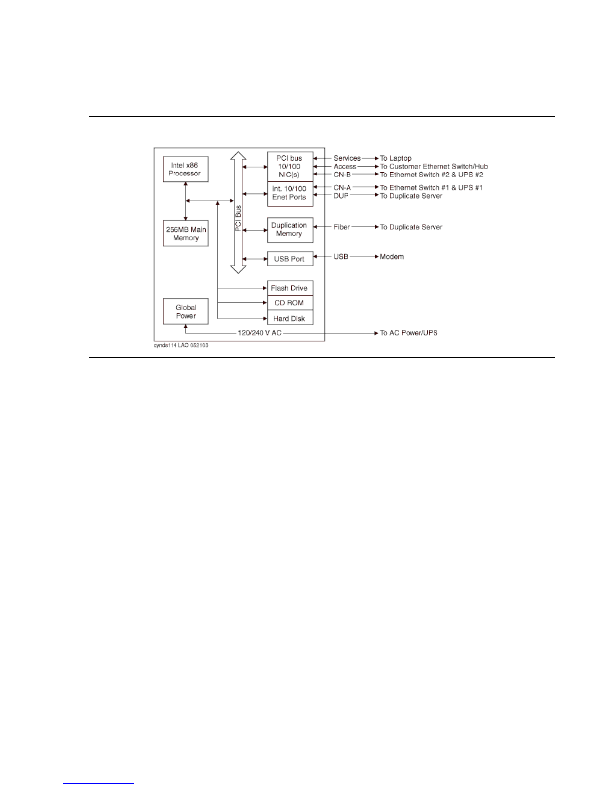
● One USB port for modem support
● One PCMCIA slot for removable Flash card support
Figure 10: Avaya S8700 series Media Server schematic
Mid-market to large enterprise
Other components
The S8700 in a Multi-Connect solution also includes the fol lowi ng components:
● An Avaya P133, P134, P333, or P334 Ethernet switch with duplication option
● One or more IP Server Interface (IPSI) circuit packs (TN2312AP)
● A Center Stage Switch (CSS) or an ATM Switch for bearer connectivity
● One or more MCC1 or SCC1 Media Gateways, also known as port networks (PNs)
Issue 3.4.1 June 2005 51
Page 52
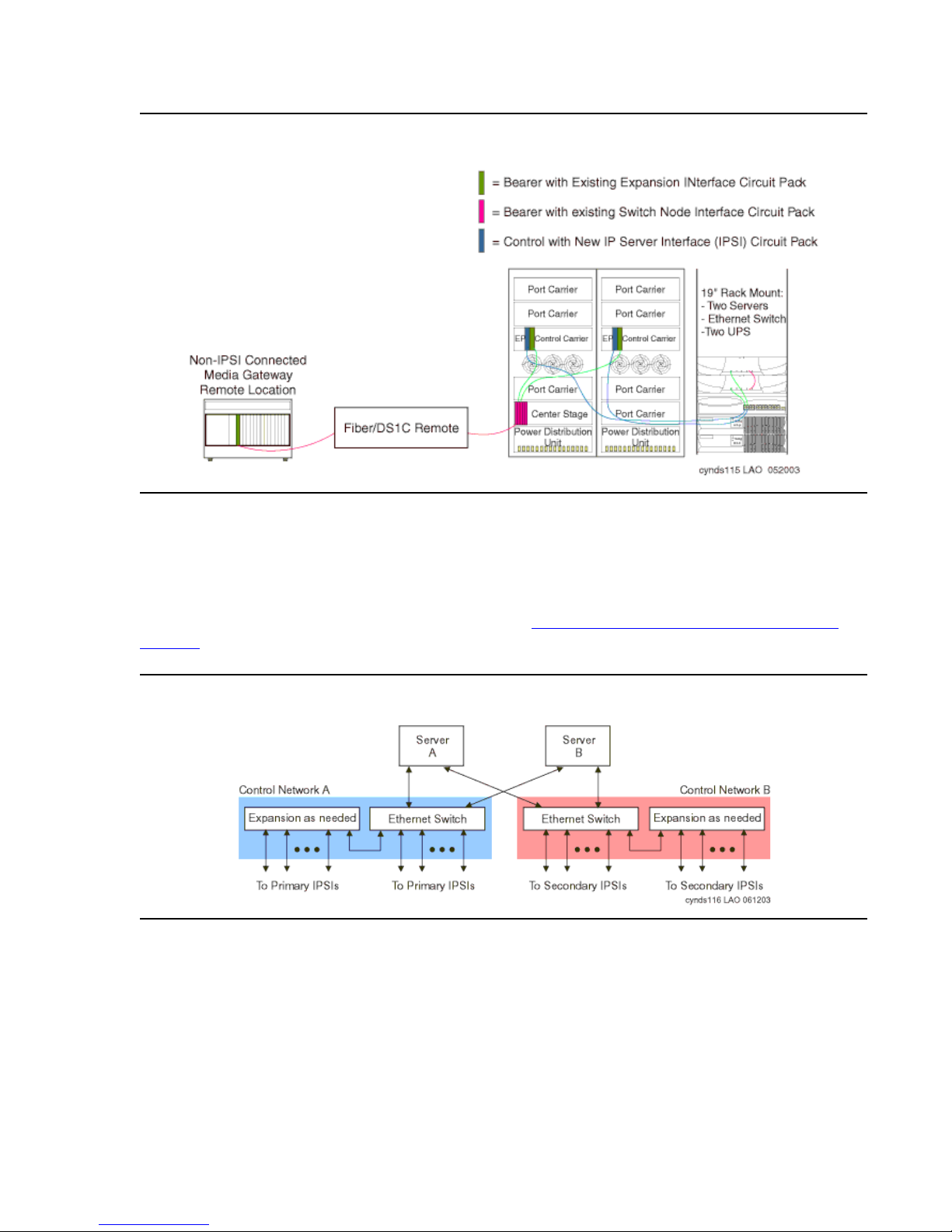
Avaya Application Solutions platforms
Figure 11: Avaya S8700/MCC1 Multi-Connect major components
Control network through an Avaya Ethernet switch
When designing S8700 Multi-Connect systems, a control net work connects the servers to the
IPSIs through a private 10/100 BaseT Ethernet. It consists of two separate Ethernet network s
made from Avaya Ethernet switches. Co ntrol network A connects to the primary IPSIs, and
control network B connects to the secondary IPSIs (Figure 12: S8700 Multi-Connect control
network).
Figure 12: S8700 Multi-Connect control network
52 Avaya Application Solutions IP Telephony Deployment Guide
Page 53
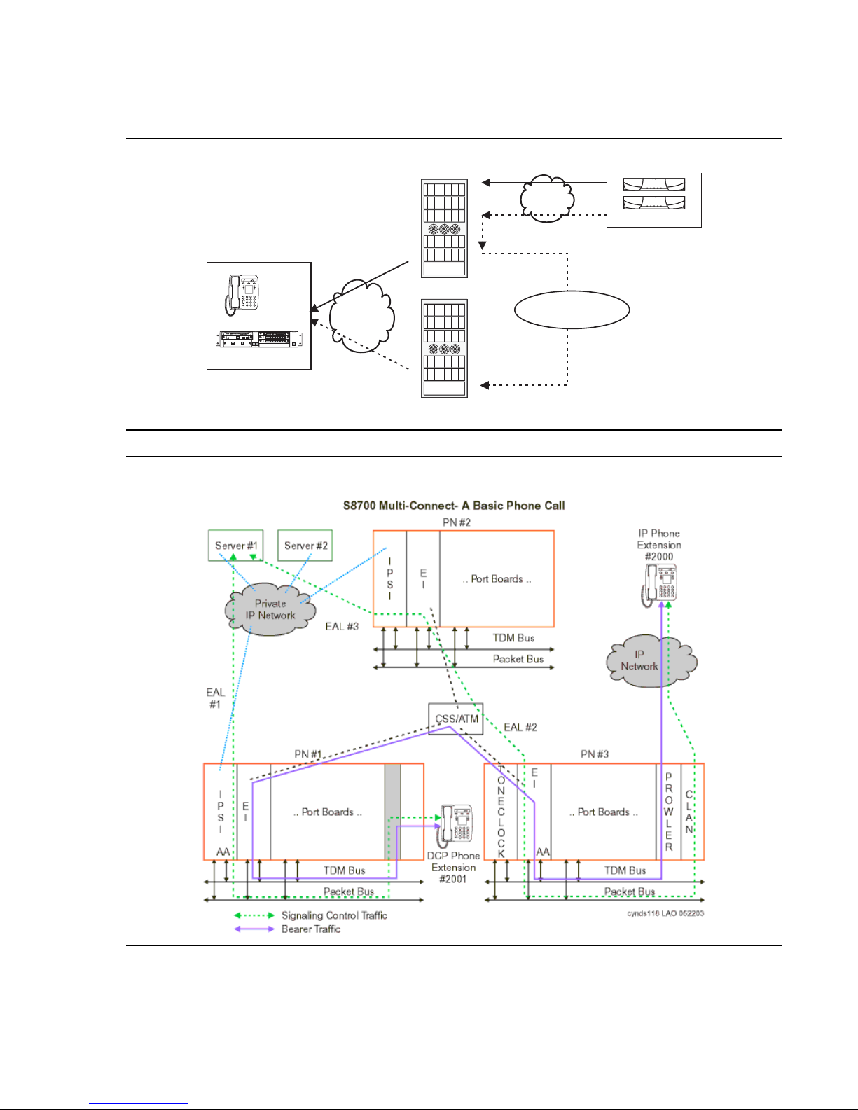
Circuit packs that support IP signaling and media traffic
ALM
TST
ACT
ALM
TST
ACT
ALM
TST
ACT
OKTO
SHUTDOWN
SERVICES
USB1
USB2
EIA 530A DCE
ALM
TST
ACT
SIG
Figure 13: S8700 / MCC1 signaling path
I
H.323 endpoint
or H.248 Gateway
IP
Phone
EISO EMEMSM EOSI
ALM
TST
ACT
SIG
E1/T1 EIA 530A DCE
ALM
ALM
TST
TST
ACT
ACT
SHUTDOWN
OKTO
REMOVE
SERVICES
USB1
USB2
1 2 3 4 5 6 87
ALM
TST
ACT
1 2 3 4 5 6 87
G700/G350
P
S
C
L
A
I
B
N
PN1
IP
C
L
A
B
N
PN2
IP
Center Stage
(non-IP)
Mid-market to large enterprise
S8700
cynds117 KLC 121003
Figure 14: S8700 Multi-Connect - a basic phone call
Issue 3.4.1 June 2005 53
Page 54

Avaya Application Solutions platforms
IP Server Interface (TN2312AP) - The IP Server Interface (IPSI) is the communication
interface between the server and the Media Gateways (por t networks). The IPSI is responsible
for gateway control, and for tunneling call control messages back to the S8700.
One IPSI circuit pack is required per IPSI-connected Media Gateway for standard reliability.
Duplicated IPSI circuit pack s are requi red per IPSI -connecte d Media Gateway f or high reliabili ty
and critical reliability.
The IPSI is located in the tone/clock slots, and provides the following functions:
● PKTINT packet bus interface
● Archangel TDM bus interface
● Tone/Clock functionality found on the TN2182B Tone/Clock circuit pack
● Ethernet interface for technician access
● Ethernet interface for connectivity to Services laptop computers
● Maintenance board interface for communication with the EPN maintenance board
Each IPSI typically controls up to five gateways by tunneling control messages over the center
stage (TDM) network to the PNs that do not have IPSIs. For locations with high IP Telephone
traffic, Avaya recommends a greater number of IPSI circuit packs.
An IPSI cannot be placed in:
● A PN that has a Stratum-3 clock interface
● A remote PN that uses a DS1 converter
● A Survivable Remote Expansion Port Network (SREPN)
The IPSI supports the following functions:
● Supports eight global Call Classification ports
● Supports network diagnostic capabili ties
● Provides PN clock generation and synchronization for Stratum-4 type II only
● Provides PN tone generation
● Provides distributed PN packet interface
● Supports the download of IPSI firmware
● Provides serial number support for License File feature activation
Control LAN (TN799DP) - The TN799DP Control LAN (C-LAN) circuit pack acts as front-end
processor and concentrator a nd provides the gat eway between the public IP Telephony network
and the S8700 system All H.323 signaling messages between IP Telephony endpoints and the
S8700 servers must pass through the C-LAN. The connectivity path between the IP endpoint
and the server is as follows:
Endpoint
⇔ IP Network ⇔ C-LAN ⇔ PN backplane ⇔ IPSI ⇔ IP network ⇔ S8700 Media
Server
54 Avaya Application Solutions IP Telephony Deployment Guide
Page 55

Mid-market to large enterprise
The C-LAN circuit pack is used for all IP call signaling f or both IP trunks and st ations. This circuit
pack also provides TCP/IP connectivity to such adjuncts and synchronous applications as Call
Management System (CMS) and INTUITY AUDIX.
This circuit pack also supports firmware download capability for all firmware-downloadable
circuit packs in a PN, whi ch allows administ rators to remot ely update the fir mware or applicati on
code of circuit packs such as the TN799DP (C-LAN) or TN2302AP Media Processor.
The S8700 platforms suppor t a maximum of 64 C-LAN cir cuit p acks per syst em. Th e number of
C-LAN circuit packs that are required depends on the number of IP endpoints that are
connected, and the options that the endpoints use. For example, it might be advantageous to
segregate IP voice control traffic from device control traff ic.
IP Media Processor (TN2302AP) - (The TN2302 (MedPro) circuit pack is a media processor
that provides a gateway between the TDM bus and the Ethernet network for the audio streams.
The S8700 Multi-Connect requires resources on a TN2302 circuit pack for IP Telephony bearer
communications. The MedPro includes a 10/100 BaseT Ethernet interface to support IP trunks
and H.323 endpoints. The MedPro can perform echo cancellation, silence suppression,
dual-tone multi-frequency (DTMF) detect ion, and conferencing.
As shown in Figure 15: TN2302AP Media Processor (MedPro) operation
on page 56, the
Media Processor converts circuit-switched audio streams to packet-switched streams. The
Media Processor supports multipl e codecs, so it can compress audio samples during
packetization. When needed for conference calls, it can also take multiple audio streams, sum
them together, and send the resulting audio stream to multiple recipients on the network.
Issue 3.4.1 June 2005 55
Page 56
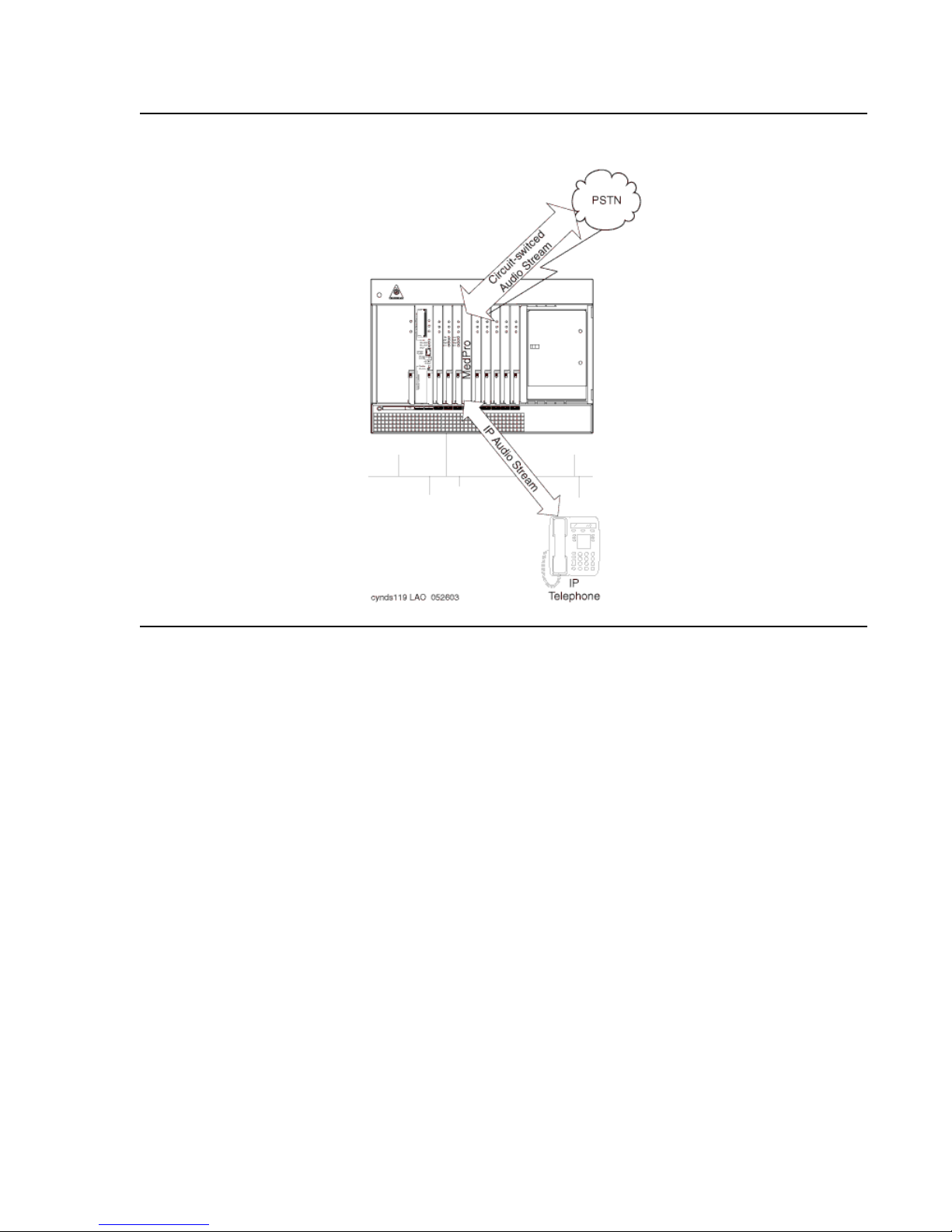
Avaya Application Solutions platforms
Figure 15: TN2302AP Media Processor (MedPro) operation
To do the job, the circuit pack has a set of DSP resources. These resources are deployed
dynamically and flexibly to any of a number of tasks, including:
● Originating and terminating IP-based packet- switched audio streams
● Establishing and maintaining an RTCP control channel for each IP audio channel
● Compressing and decompressing audio (for example, G.729 to G.711)
● Terminating TCP for an incoming T.120 data stream, and transcoding it to H.221-
compliant format for transmission onto the TDM bus and vice-versa
● Summing multiple audio channels into a composite signal for audio conferencing
The S8700 series Media Server is responsible for sending messages to the circuit pack to
allocate and to configure the DSP resources to the required task and connecting multiple
resources into a chain that performs the desired media process ing function. In addition, the
Media Server sends the information to the destinati on of these audio streams.
56 Avaya Application Solutions IP Telephony Deployment Guide
Page 57

Since H.323 allows any of several different codecs to be used for encoding an audio stream on
the IP network, the Prowler board is able to use any of the following codecs:
● G.711
● G.723.1
● G.729 (A, B)
In the same way that a MedPro interfaces with IP Telephony endpoints, it can connect to
another MedPro to interconnect two or more Avaya switches in an IP network over an IP trunk.
Media Gateways
The MCC1, SCC1, G700, and G350 Media Gateways are supported in a Multi-Connect
configuration.
S8700 Multi-Connect can have a mixture of MCC1 and SCC1 cabinets in a system. However,
the type of cabinet cannot be split within a Port Networ k.
Multi-Carrier Cabinet (MCC1) Media Gateway - The MCC1 Media Gateway can contain up t o
five of the following carriers:
Mid-market to large enterprise
● A Port Carrier that contains one or more of the following:
- Port circuit packs
- VOIP conversion resources
- Service circuit pac ks
- Tone clocks
- Expansion Interface (EI ) circuit packs
● A Switch Node Carrier that contains Switch Node Interface circuit packs that compose the
Center Stage Switch (CSS).
● An Expansion Control Carrier that contains service slots and port slots.
The MCC1 Media Gateways can support a maximum of 98 trunk or line port circuit packs.
Issue 3.4.1 June 2005 57
Page 58
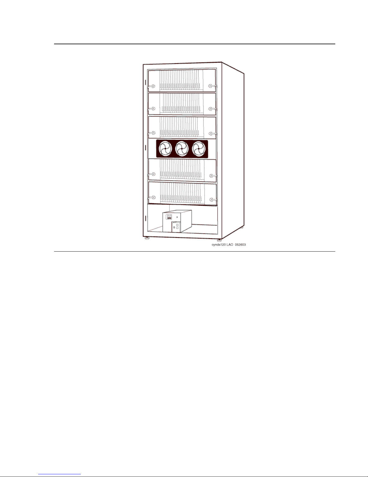
Avaya Application Solutions platforms
Figure 16: MCC1 Media Gateway
Single-Carrier Cabinet (SCC1) Media Gateway - The SCC1 Media Gateway consists of a
single carrier. Up to four SCC1 Media Gateways can be connected together in one location to
form one port network. There are two types of SCC1 Media Gateways:
● An Expansion Control Cabinet that contains service slots and port slots.
● A Port Cabinet that contains ports and interfaces to an Expansion Control Cabinet.
58 Avaya Application Solutions IP Telephony Deployment Guide
Page 59
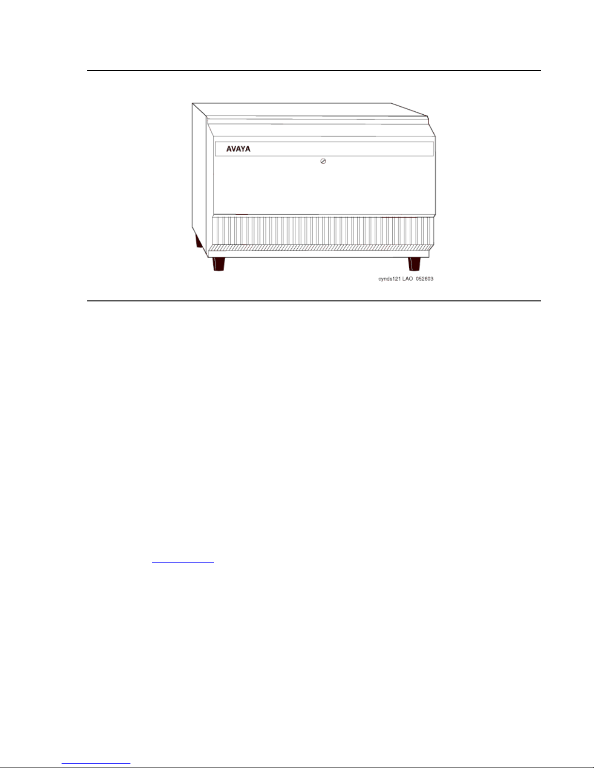
Figure 17: SCC1 Media Gateway
Mid-market to large enterprise
Non-IPSI connected Media Gateway - Typically, one of every five Port Networks (PNs)
contains one or two IPSI circuit packs. The remaining PNs are referred to as non-IPSI
connected. Non-IPSI connected PNs get their control information from the servers through one
of the PNs that does contain an IPSI. Such control messages are “tunneled” through the
circuit-switched network. The system software controls this communication and allocation. The
software automaticall y rout es the control messages through an appropriate IPSI. There is no
need to administer which IPSI controls the non-IPSI connected PNs. The system automatically
allocates those resources, and also compensates for any component failure.
Remote MCC1\SCC1 Media Gateways - The dedicated control network for an S8700 with
MCC1 or SCC1 Media Gateway can be extended to an IPSI in a remote media gateway. But for
cost effective ness and straightforward installation, Avaya recommends that all of the
IPSI-connected media gateways be collocated with the S8700 and Ether net switches. The
circuit-switched network dictates the available options.
Non-IPSI connected media gateways ’ circuit-switched network can be extended through all the
options available with DEFINITY G3r. Center Stage Switch configurations can use fiber
extenders or DS1-Converter (DS1-C) fac il ities, allowing the media gateway separation to be
essentially limitless. When ATM-PNC is used, the media gateway separation is also essentially
limitless (se e ATM network
on page 60).
Issue 3.4.1 June 2005 59
Page 60

Avaya Application Solutions platforms
Remote G700 or G350 Media Gateway - The S8700 series Media Server can provide the call
processing features for a remote G700 or G350 media gateway over an H.248 link. In this
configuration, S8700 can support up to 250 G700 or G350 Media Gateways. An S8300 media
module that is located in a G700 or G350 Media Gateway in a remote location provides
survivability when the primary cont roller is inaccessible. For more information, see S8300 as the
Local Survivable Processor (LSP) on page 40.
Center Stage Switch
The Center S tage Switch (C SS) is a connection hub that pr ovides Port Network communi cation.
A CSS can be used when the Multi-Connect Solution that is composed of more than three Port
Networks. Often, the CSS is incorporated into smaller configurations to allow for growth. The
CSS consists of from one to three switch nodes (SN), which reside in a Port Network carrier.
SNs are composed of one or two switch node carriers, depending on whether the solution is
being duplicated for critical reliability. Port Network expansion depends on internal SN-to-SN
traffic, accordi ng to the following guidelines:
● 1 SN expands from 1 to up to 15 PNs.
● 2 SNs expands to up to 29 PNs.
● 3 SNs expands to up to 44 PNs.
ATM network
The Asynchronous Transfer Mode (ATM) switch is a replacement option for the CSS, or for the
direct-connect switch. Several Avaya ATM switch types can provide Port Network connectivity.
Non-Avaya ATM switches that comply with the ATM st andards that are set by the European
Union can also provide Port Network connectivity.
With S8700 Multi-Connect, ATM-Port Network Connectivity (ATM-PNC) allows any ATM switch
or ATM network that complies with specified st andard s and cap acit ies to serv e as the means to
connect to the PN. In this type of configuration, the ATM switch or network replaces the CSS.
ATM-PNC is used to connect port networks within a single switch. The WAN Spare Processor
(WSP) is not supported. One ATM supports up to 64 PNs.
60 Avaya Application Solutions IP Telephony Deployment Guide
Page 61

Mid-market to large enterprise
S8700 Multi-Connect configuration for higher availability
When used with the MCC1, SCC1, G700, or G350 Media Gateways, the S8700 series Media
Server has the following reliability options:
● Standard reliability configuration
● High reliability configuration
● Critical reliability configuration
Standard reliability configuration
The standard reliability option is the most basic option that consists of the fol lowing
components:
● Two S8700 series Media Servers
● Server-to-IPSI control is not duplicated
● One UPS unit for each S8700 Media Server. Using two UPS units ensures that a single
UPS failure or repair operation does not disable the system.
● One IPSI in each IPSI-connected port network
● Circuit-switched traffic between po rt networks i s carried on a simplex net work that is made
up of one Expansion Interface (EI) in each port net work. The EIs are cabled with lightg uide
fiber to either the Center Stage Switch (CSS) or an Asynchronous Transfer Mode (ATM)
switch.
Figure 18: S8700 Multi-Connect in a standard reliability configuration
on page 62 shows an
example of a standard reliabilit y configuration.
Issue 3.4.1 June 2005 61
Page 62
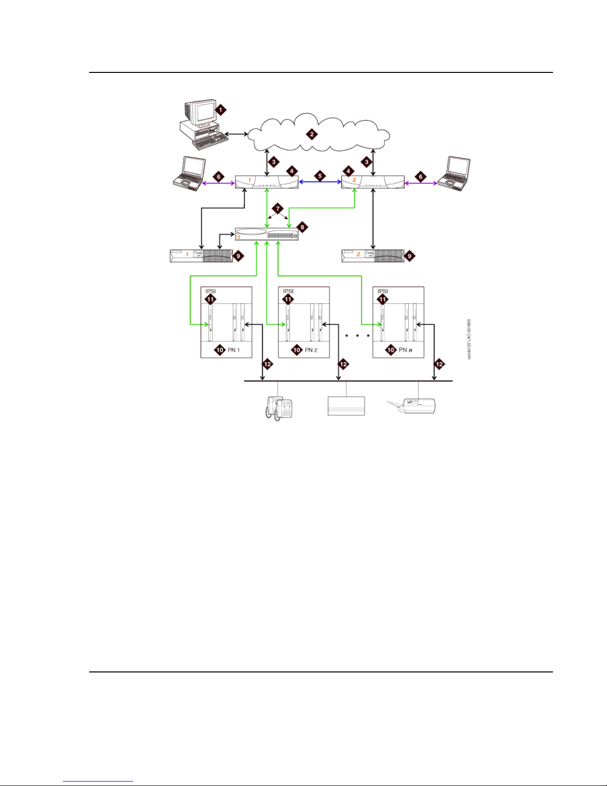
Avaya Application Solutions platforms
Figure 18: S8700 Multi-Connect in a standard reliability configuration
Figure notes:
1. The Administration PC accesses the S8700
series Media Server over the corporate data
network.
2. Corporate IP network.
3. Corporate IP network interface. The Ethernet 4
link from the S8700 to the data network.
4. Two S8700s are always present. One server is
in active mode, and the other server is on
standby.
5. Duplication interface, default Ethernet 2. The
dedicated Ethernet connection between the
S8700 Media Servers.
6. Services interface, default Ethernet 1. The
server’s dedicated Ethernet connection from
the S8700 to a laptop computer (active only
during on-site administration or on-site
maintenance).
1. The Ethernet connection to the corporate network in this figure is a nondedicated network. IP addresses for the various
components of the S8700 Multi-Connect Media Server must be administered to prevent conflicts with other equipment
that shares the network. In the default S8700 Multi-Connect configuration, all other Ethernet connections operate on
their own closed LANs.
1
7. Network control A interface, default Ethernet 0. The
server’s Ethernet connection to one or two Ethernet
switches. This Ethernet link carries the control signals for
the S8700 Multi-Connect PNs.
8. Ethernet switch. At least one Ethernet switch is required
to support the S8700 Multi-Connect control network. If
many PNs are present, two Ethernet switches can be
daisy-chained together to provide sufficient Ethernet
connections to the IPSI boards in the PNs.
9. UPS. Keeps the S8700 Media Servers and the Ethernet
switches function a l dur ing brief power outage s.
10. PN. Provides the telecommunications functions of the
S8700 Multi-Connect Media Server.
11. IPSI. The IPSI circuit pack carries the control network
signals to the PNs, and provides tone clock functionality.
12. Bearer connectivity over Center Stage Switch or ATM.
62 Avaya Application Solutions IP Telephony Deployment Guide
Page 63

Mid-market to large enterprise
High reliability configuration
The high reliability configuration option builds on the standard reliability option. The high
reliability option duplicates components, so that no single point of failure exists in the control
network. The high reliability configuration consists of the following components:
● Two S8700 series Media Servers
● Two IPSI circuit packs in each IPSI-connected port network
● Two Ethernet switches
● Two UPS units
Circuit-switched traf fic between port net works is carried on a simplex net work that is made up of
one Expansion Interface (EI) in each port network. The EIs are cabled with lightguide fiber to
either the Center Stage Switch (CSS) or an Asynchronous Transfer Mode (ATM) switch.
Figure 19: S8700 Multi-Connect in a high reliability configuration
example of a high reliability configur ation.
on page 64 shows an
Issue 3.4.1 June 2005 63
Page 64
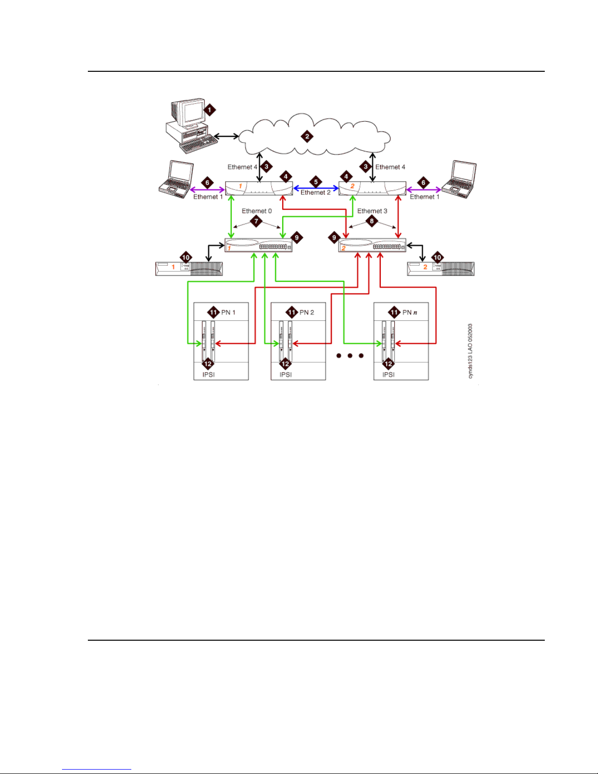
Avaya Application Solutions platforms
Figure 19: S8700 Multi-Connect in a high reliability configuration
Figure notes:
1. The Administration PC is used to access
the S8700 series Media Server over the
corporate data network.
2. Corporate IP network.
3. Corporate IP network interface. The
Ethernet 4 link from the S8700 Media
Server to the data network.
4. Two S8700 Media Servers are always
present. One server is in active mode,
and the other server is on standby.
5. Duplication interface, default Ethernet 2.
The dedicated Ethernet connection
between the S8700 Media Servers.
6. Services interface, default Ethernet 1. The
server’s dedicated Ethernet connection
from the S8700 Media Server to a laptop
computer (active only during on-site
administration or on-site maintenance).
1. The Ethernet connection to the corporate network in this figure is a nondedicated network. IP addresses for
the various components of the S8700 Multi-Connect Media Server must be administered to prevent conflicts
with other equipment that shares the network. In the default S8700 Multi-Connect configuration, all other
Ethernet connections operate on their own closed LANs.
1
7. Network control A interface, default Ethernet 0. The
server’s Ethernet connection to one or two
Ethernet switches. This Ethernet link carries the
control signals for the S8700 Multi-Connect PNs.
8. Network control B interface, default Ethernet 3. The
server’s Ethernet connection to one or two
Ethernet switches. This Ethernet link carries the
control signals for the S8700 Multi-Connect PNs.
9. Ethernet switches. If many PNs are present, two
Ethernet switches can be daisy-chained together to
provide suffic ie nt Ethernet connections t o the IPSI
boards in the PNs.
10. Duplicated UPSs. Keeps the S8700 Media Servers
and the Ethernet switches functional during brief
power outages.
11. Port Networks. Provides the telecommunications
functions of the S8700 Multi-Connect Media Server.
12. Duplicated IPSI circuit packs
64 Avaya Application Solutions IP Telephony Deployment Guide
Page 65

Mid-market to large enterprise
Critical reliability configuration
The critical reliability configuration option is built upon the high reliability configuration. In the
critical reliability configuration, the bearer network has duplicated components so that there is
no single point of failure. The crit ic a l re liability confi guration consists of th e fo llo w ing
components:
● Two S8700 series Media Servers
● Two IPSI circuit packs in each IPSI-connected port network
● Two Ethernet switches
● Two UPS units
● Two CSS/ATM EI (Expansion Interface) in every port network
S8700 Multi-Connect survivability
In addition to the high reliability of the duplicated S8700 Multi-Connect Media Servers, the
S8300 Media Server in a Local Survivable Processor (LSP) configuration can be used to
provide survivability. Additional recovery capability is embedded in the Communication Manager
that resides on the S8700 Media Server.
Avaya S8700 series Media Server IP-Connect configuration
The S8700 IP-Connect configuration is an all-I P solution that is built on open IP network
connection. This solution is designed for medium to lar ge enterprises. The main difference
between the IP-Connect Solution and Multi-Connect solution is that IP-Connect uses the IP
network for all inter-gateway communication, where Multi-Connect also uses CSS or ATM
networking.
As Table 12: Capacity limits for S8700 / G650 / G700 / G350 IP-Connect solution
shows, the system supports up to 12,000 IP stations, 8,000 non-IP stations, and 8,000 IP and
non-IP trunks, with the capacity of 100,000 General Business call mix BHCC. The IP-Connect
platform is scalable to 64 Port Networks, each of which can house up to four G650s and up to
250 G700 or G350 Media Gateways. The Media Server complex still consists of duplicated
S8700 servers. One server is active, and the other server is on standby. Table 13: Scalability
for S8700 / G650 / G700 / G350 IP-Connect solution on page 68 shows the IP-Connect G700/
G350 capacities.
Figure 20: Avaya S8700 with remote G650 / G700 / G350 Media Gateways
an example of an S8700 with remote G700 Media Gateways.
on page 67
on page 66 shows
Issue 3.4.1 June 2005 65
Page 66
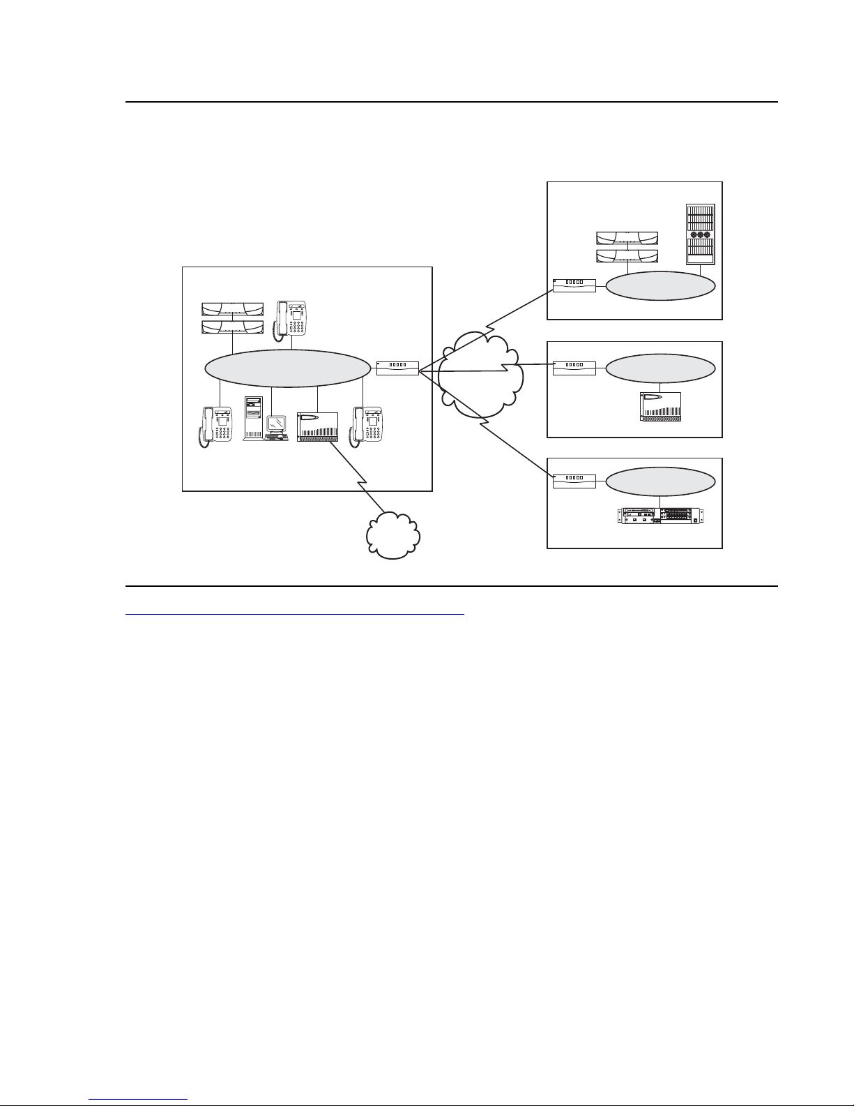
Avaya Application Solutions platforms
ALM
TST
ACT
ALM
TST
ACT
REMOVE
ALM
TST
ACT
OKTO
SHUTDOWN
SERVICES
USB1
USB2
E1/T1
EIA 530A DCE
ALM
TST
ACT
SIG
Figure 20: Avaya S8700 with remote G650 / G700 / G350 Media Gateways
S8700 system with remote G650/G700 sites and
IPTIETrunk links to other Avaya PBXs
S8700
Servers
IP
Phone
IP Trunk QSIG
Location with another
Avaya IP PBX
Avaya IP PBX
(S8300,S8700)
Edge
Router
Ethernet
Remote site with G650
Ethernet
Edge
Router
WAN
Edge
Router
Ethernet
G650 gateway
IP
Phone
PC
G650
Gateway
DCP
PRI
PSTN
Remote site with G700/G350
Ethernet
Edge
Router
ALM
TST
ACT
OKTO
REMOVE
EISO EMSM EOSI
ALM
TST
ACT
SIG
E1/T1
EIA 530A DCE
ALM
TST
ACT
SHUTDOWN
SERVICES
USB1
USB2
1 2 3 4 5 6 87
ALM
TST
ACT
1 2 3 4 5 6 87
G700/G350 gateway
cynds125 LAO 101104
Figure 21: S8700 IP-Connect - a basic phone call on page 67 shows a call through an S8700
IP-Connect system.
66 Avaya Application Solutions IP Telephony Deployment Guide
Page 67
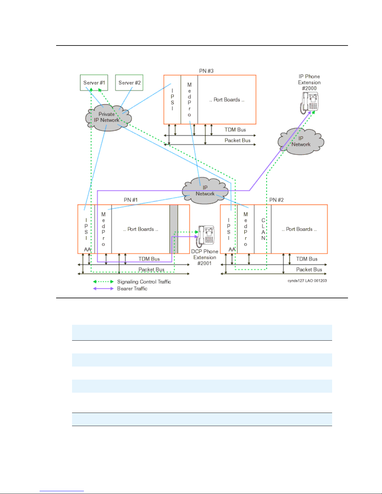
Figure 21: S8700 IP-Connect - a basic phone call
Mid-market to large enterprise
Table 12: Capacity limits for S8700 / G650 / G700 / G350 IP-Connect
solution
Feature Capacity
General Business Busy Hour Call Completion Up to 100,000
Number of stations Up to 12,000
Number of IP users (IP trunks + IP stations) Up to 12,000
Number of non-IP users Up to 8,000
Number of trunks (independent of the number of
users)
Up to 4,000 (up to 1000 SIP
trunks)
1 of 2
Issue 3.4.1 June 2005 67
Page 68

Avaya Application Solutions platforms
Table 12: Capacity limits for S8700 / G650 / G700 / G350 IP-Connect
solution (continued)
Feature Capacity
Total number of ports Up to 16,000
Number of IP users: G700 or G350 / Total IP users
(cannot be combined with non-IP users)
Number of non-IP users: G700 or G350 / Total
users (cannot be combined with IP users)
Table 13: Scalability for S8700 / G650 / G700 / G350 IP-Connect solution
Feature Capacity
Number of G700 or G350 Media
Gateways
Number of G650 Media Gateways
(port networks)
Number of LSPs per server Up to 50
Number of G700 or G350 gateways per
LSP
Main components
Up to 5,000/12,000
Up to 5,000/12,000
2 of 2
Up to 250
Up to 64 PNs
Up to 50
The S8700 IP-Connect consists of the following main components:
● Duplicated S8700 series Media Servers
● Two UPS units, one for each server
● Two Abstract Control Modem (ACM) compliant Universal Serial Bus (USB) modem
● At least one IPSI
● TN799DP C-LAN (for IP endpoint signaling)
● At least one TN2302AP IP Media Processor to support inter-port and intra-port network
media connectivity
● The G650 Media Gateway
● Avaya Communication Manager
Figure 22: S8700 Media Server IP-Connect major components
S8700 IP-Connect components mounted in an open EIA-310-D- compliant, 19-inch data rack.
68 Avaya Application Solutions IP Telephony Deployment Guide
on page 69 shows the m ain
Page 69
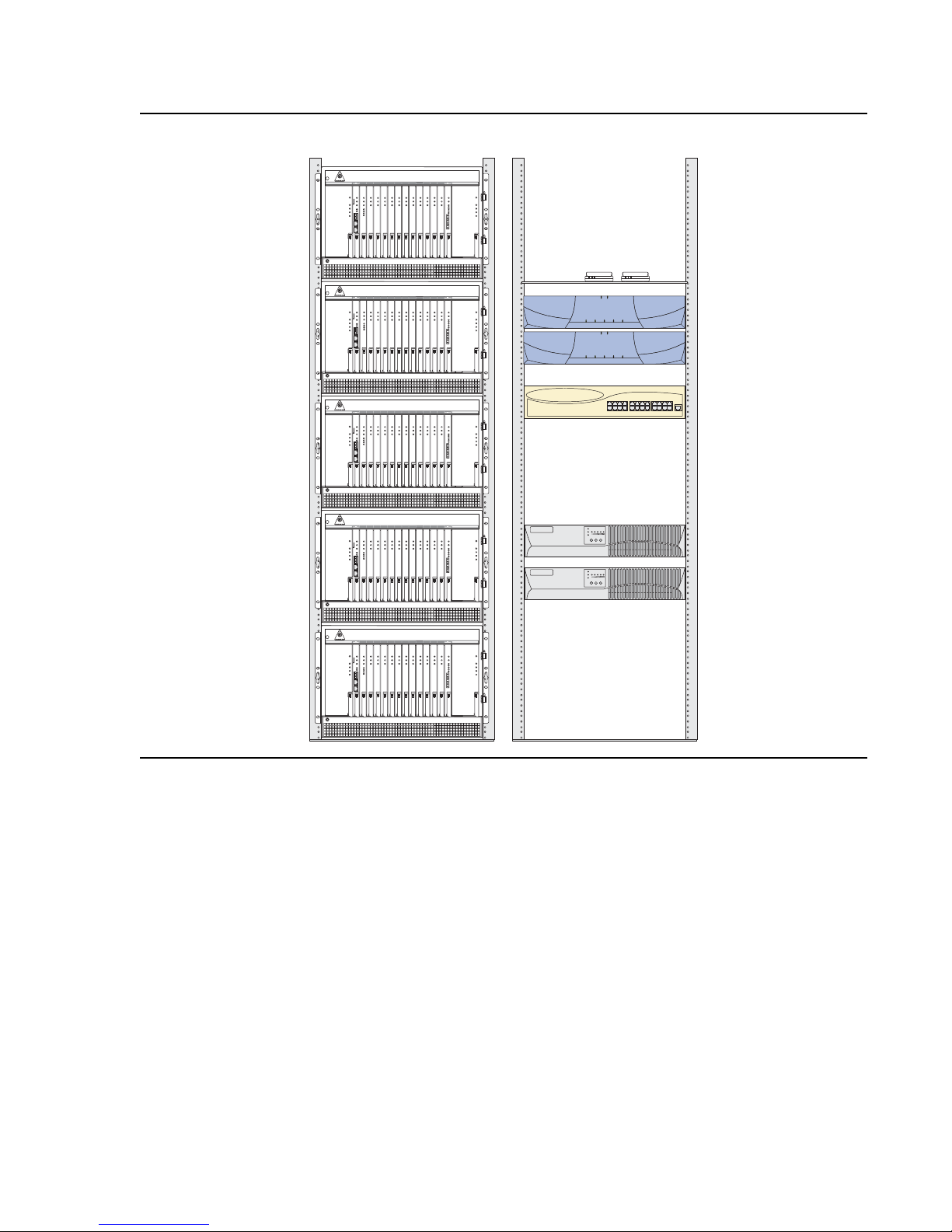
Figure 22: S8700 Media Server IP-Connect major components
Mid-market to large enterprise
FAN OR POWER FAIL
FAN AND POWER OK
E
FAN OR POWER FAIL
FAN AND POWER OK
D
FAN OR POWER FAIL
FAN AND POWER OK
C
FAN OR POWER FAIL
FAN AND POWER OK
B
1
2
AC INPUT
DC INPUT
ACTIVE RING
1
2
AC INPUT
DC INPUT
ACTIVE RING
103 456 8 9Power
7 111213 Power
7 111213 Power
14
FAN OR POWER FAIL
FAN AND POWER OK
ACTIVE RING
103 456 8 9Power
14
FAN OR POWER FAIL
FAN AND POWER OK
ACTIVE RING
AC INPUT
DC INPUT
AC INPUT
DC INPUT
2
1
1
2
AC INPUT
DC INPUT
ACTIVE RING
1
2
AC INPUT
DC INPUT
ACTIVE RING
103 456 8 9Power
7 111213 Power
7 111213 Power
14
FAN OR POWER FAIL
FAN AND POWER OK
ACTIVE RING
103 456 8 9Power
14
FAN OR POWER FAIL
FAN AND POWER OK
ACTIVE RING
1
AC INPUT
DC INPUT
AC INPUT
DC INPUT
2
1
13
12
CONSOLE
24
1
FAN OR POWER FAIL
FAN AND POWER OK
A
1
2
AC INPUT
DC INPUT
ACTIVE RING
103 456 8 9Power
7 111213 Power
14
FAN OR POWER FAIL
FAN AND POWER OK
ACTIVE RING
AC INPUT
DC INPUT
cynds126 KLC 121003
The left data rack contains a stack of five G650 Media Gateways that are labeled A through E.
The right data rack contains the following (from top to bottom):
● Two USB-compliant modems
● Two S8700 series Media Servers
● One Avaya Ethernet switch
● Two AS1 UPS units
Issue 3.4.1 June 2005 69
Page 70
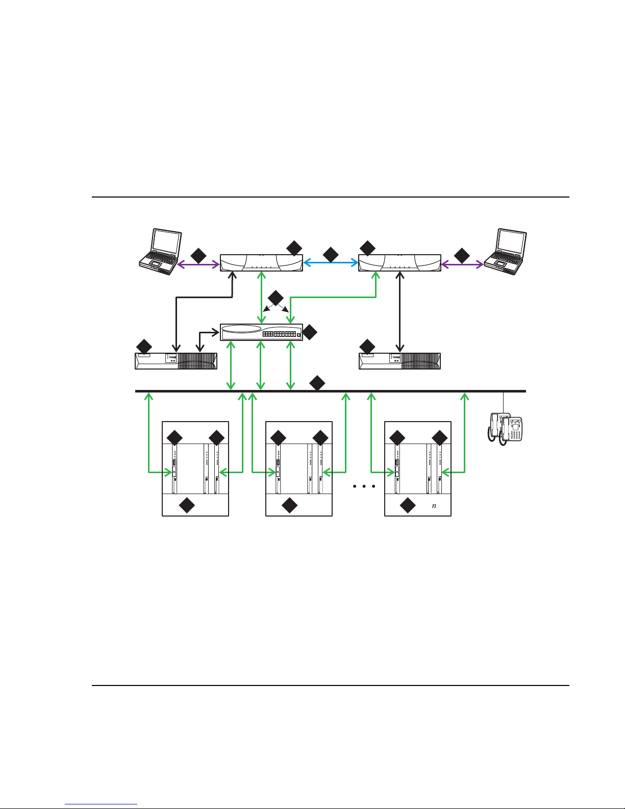
Avaya Application Solutions platforms
S8700 IP-Connect reliability configurations
The S8700 series Media Servers are duplicated. The control and bearer links are not
duplicated. The clock functional ity is provided by the IPSI circuit pack in each port network. As
an all-IP solution, the S8700 IP-Connect only supports IP media gateways. The S8700
IP-Connect does not support traditional CCS- or A T M-connected media gateways.
S8700 IP-Connect configuration
Figure 23: S8700 IP-Connect configuration
6 6
Figure notes:
3 3
1
1 1
2
2
4
112
1
13 24
CONSOLE
5
12
9
IPSI IPSI
8 8
100bT
BBI
LINK
LINK
TRMT
TRMT
RCV
RCV
7 7
PN 1
100bT
LINK
TRMT
RCV
PN 2
BBI
LINK
TRMT
RCV
IPSI
8
101010
100bT
BBI
LINK
LINK
TRMT
TRMT
RCV
RCV
7
PN
cynds128 KLC 121003
1. Two S8700 series Media Servers. One server is in
a active mode, and the other server is on
standby.
2. Duplication Interface. The Ethernet connection
between the two S8700 Media Servers.
3. A dedicated Ethernet connection to a laptop
computer. This connection is active only dur ing
on-site administration or maintenance, and the
Services interface can link to the non-active
server through a telnet session.
4. Connection from the servers to the Ethernet
switch.
70 Avaya Application Solutions IP Telephony Deployment Guide
5. Ethernet switch. A device that provides port
multiplication on a LAN by creating more than
one network segment.
6. UPS units. Two UPS units are required
7. Port Network. An optional configura tion of Me dia
Gateways that provides increased port capacity.
8. IPSI. A circuit pack that transports control
messages over IP. The IPSI circuit pack is used
so that the S8700 Media Server can
communicate with the Port Networks.
9. Customer LAN.
10. TN799 Control-LAN (C-LAN)
Page 71

DEFINITY Servers R and SI
Avaya Communication Manager with an Avaya DEFINITY® Server R or Avaya DEFINITY®
Server SI offers are targeted at the application -i ntensiv e mar ket segment . This market segment
is characterized by multiple loc a tions that use many applications today, with the anticipation of
adding more. Circuit-switched voi ce communication is cri tical for these customers . However , the
strategic direction is IP Telephony, including voice/data network integration, unified mes saging,
and multimedia conferencing and collaboration. Most customers who use these solutions also
use some form of centralized decision-making for all their sites. DEFINITY offers a flexible
solution, scaling up to 25,000 endpoints. Thus, DEFINITY offers the ability to grow without the
need to change an entire communications system.
More information about these two platforms is available on the Avaya Support web site.
S8710 Media Server
The Avaya S8710 Media Server Platform is a new high-performance Intel Xeon-based server
running Avaya Communication Manager (CM) software that will replace the S8700 media
server. The S8700 media server will be marked "End of Sale" upon release of the S8710. The
S8710 system supports the Avaya MCC1, SCC1, CMC1, and G650 Media Gateways. The
Avaya G700 and G350 Media Gateways are also supported if there is a TCP/IP connect ion
between the media gateway and a C-LAN circuit pack located in a MCC1, SCC1, CMC1, or
G650 Media Gateway. The S8710 has the capacity to support up to 64 port networks. It
supports IP-Connect and Multi-Connect implementations, while offering enhanced capacity, as
summarized in Table 14: S8710 feature capacities
Mid-market to large enterprise
.
Table 14: S8710 feature capacities
Feature Capacity
General Business Busy Hour Call
Completion
Number of stations + trunks Up to 44,000
Number of IP users (IP trunks + IP
stations)
Number of trunks (IP trunks and non-IP
trunks)
Number of stations Up to 36,000
Total number of ports Up to 44,000
Up to 375,000 (analog equivalent)
Up to 125,000 (IP station to trunk
call)
Up to 12,000
Up to 8,000
1 of 2
Issue 3.4.1 June 2005 71
Page 72
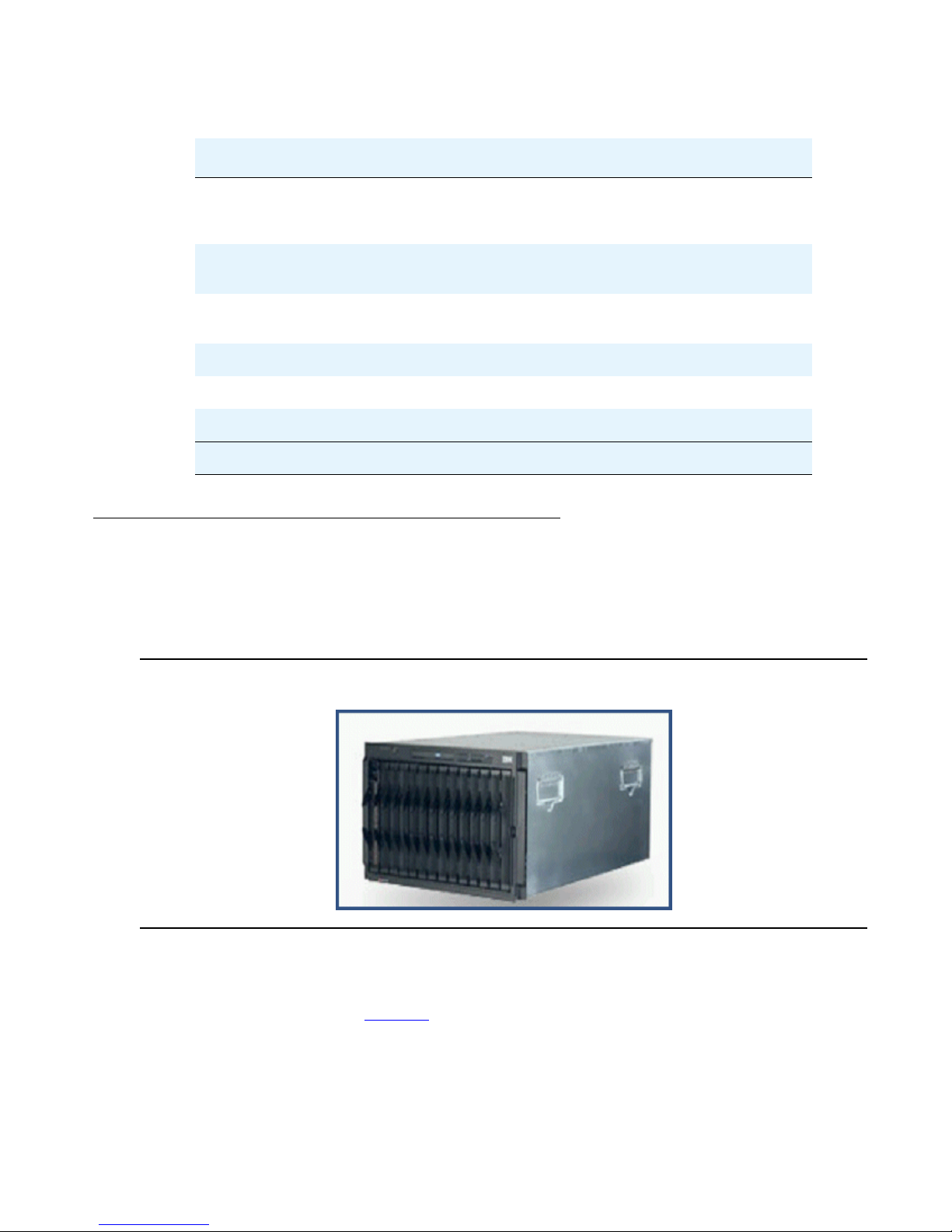
Avaya Application Solutions platforms
Table 14: S8710 feature capacities (continued)
Feature Capacity
Number of IP users: G700 or G350 / Total
IP users (cannot be combined with non-IP
users)
Number of non-IP users: G700 or G350 /
Total users
Number of G700/G350 Media Gateways
Up to 250
Number of G650 Port Networks Up to 64
Number of G700/G350 Gateways per LSP Up to 50
Number of LSPs per server Up to 250
Service Provider — Blade Server
Avaya’s Hosted IP Telephony offer uses the IBM eServer Blade Center Media Server to
facilitate service provider IP Telephony deployments. The Blade Server supports CM 2.2
running on up to 14 server blades per chassis, or 82 blades per rack.
Up to 5,000/12,000
Up to 5,000/36,000
Up to 250
2 of 2
Figure 24: IBM eServer Blade Center Media Server
In a hosted IP Telephony offer, each customer would have its own server blade , each of whic h is
capable of supporting up to 500 users, 92 trunks, and 500 IP endpoints. In addition, each blade
can support 50 G350 or G700 media gateways, 50 G650 gateways, and 50 LSPs. The blade
server capacities are listed in Table 15
.
72 Avaya Application Solutions IP Telephony Deployment Guide
Page 73

Other Avaya IP Telephony servers
The IBM blade server offers a 50% improvement in server density over the S8500 server. This
platform is appropriate for hosting IP Telephony deployments for many small- to mid-sized
enterprises. Hot-pluggable components with redundant power supplies, fans, and Gigabit
Ethernet cards increase the platform’s serviceability. In addition, a NEBS-compliant version is
available upon request.
Table 15: IBM eServer Blade Center Media Server specifications
Feature Capacity
Communication Manager release 2.2
Number of Stations 500
Number of Trunks 92
Number of IP Endpoints 500
Number of Media Gateways (G700/
G350)
Number of LSPs (increased with CM
2.2)
Number of Port Networks (G650) Up to 50
Supported Gateways G700, G350, G650 for
Data Rack Requirements 4-post rack
Other A v aya IP Telephony servers
Avaya IP Office
Avaya IP Office is another standalone Avaya platform that supports IP Telephony for the small
to mid-size m a rket.
Up to 50
Up to 50
new installs (support
of existing G600s)
Avaya IP Office is an IP PBX for 10 to180 stations. Avaya IP Office is not part of the Avaya
Application Solutions offer, and thus is not covered extensively in this document. More
information about the IP Office is available on the Avaya Support web site.
Issue 3.4.1 June 2005 73
Page 74

Avaya Application Solutions platforms
74 Avaya Application Solutions IP Telephony Deployment Guide
Page 75

Greenfield deployment
This chapter explains how to implement Avaya Appli cation Solutions components in a
Greenfield site. A Greenfield site is a business or an organizatio n that does not have an existing
communication system. Most Greenfield systems are deployed into new businesses and
organizations, and these systems tend to be smaller in size. Occasionally, an established large
organization may completely remove its existing system and install a new system. In these
cases, the incumbent system is usually a leased service, such as a centrex service from a
telephony service provider.
In general, most organizations want to protect their investment in their PBX communications
system. Avaya provides ways for our circuit switched PBX customers to evolve from circuit
switched systems to IP-enabled systems. This solution provides most of the advantages of IP
Telephony with minimal equipment upgrades to an enterprise’s existing PBX. The evolution
approach is described in Evolution from circuit-switched to IP
Components needed for Greenfield deployment
on page 85.
In a Greenfield deployment, the primary connection medium is IP. To provide the greatest
flexibility and the lowest costs for a converged solution, most endpoint s should be IP
Telephones or IP Softphones. A mixture of IP endpoint s and circuit-switched endpoints places
increased demand on Media Processor resources, and thus increases the cost of the
deployment. Intersite communicat ions should also be IP based. This can be done eith er through
direct connections between IP Telephones or through IP trunks. Ci rcuit -switched or TDM-based
communications should be kept to a minimum. The primary TDM connections should be for
PSTN access, where necessary, and connections to any analog telephones, modems, or fax
machines that exist (Figure 25: A Greenfield IP Telephony deployment
In a Greenfield deployment, the emphasis is on IP Telephony. Multi-Connect systems that
emphasize TDM connections are not generall y recommended, except in speci al circumstances .
Those circumstances include when there is a need for:
● Critica l re l ia b ility
● Significant analog or DCP endpoints
on page 76).
Issue 3.4.1 June 2005 75
Page 76
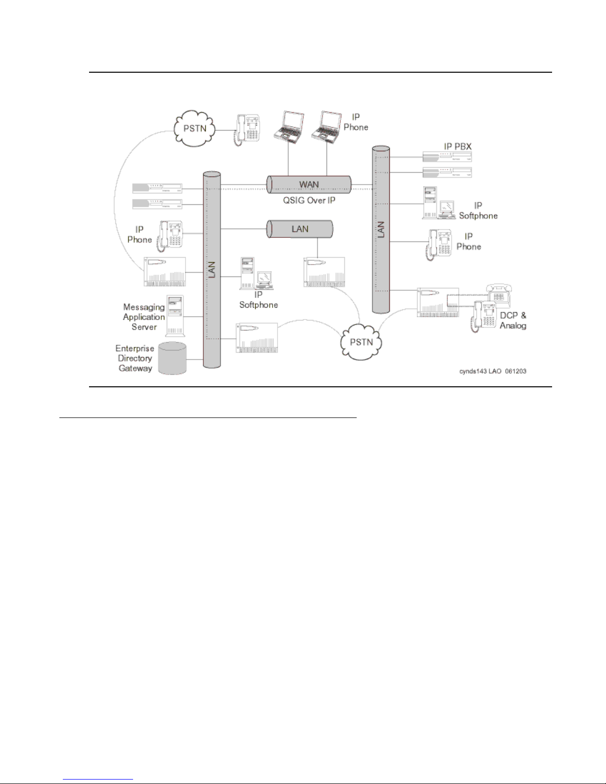
Greenfield deployment
Figure 25: A Greenfield IP Telephony deployment
Media Server (H.323 Gatekeeper)
The Media Servers are responsi ble for running Avaya Communi cation Manager and controlling
the Media Gateways and endpoints. The Media Servers control the dial plan translations and
call routing, call setup and tear down, Cal l Detail Record (CDR) generation, traffic management.
The Media Servers also offer H.323 gatekeeper functionality, and provide the extensive
telephony features that are included with Avaya Communication Manager.
Avaya’s Linux-based servers include:
● S8300 Media Server (The server resides in the G700 or G350 Media Gateway)
● S8500 Media Server
● S8700 series Media Server
76 Avaya Application Solutions IP Telephony Deployment Guide
Page 77

Avaya Communication Manager
Communication Manager IP cap abiliti es and appli cations suppor t voice o ver an I P network, a nd
ensure that remote workers have access to communication system features from their PCs.
Communication Manager also provides standards-based control between Media Servers and
Media Gateways, which allows the communications infrastructure to be distributed to the edge
of the network. The Communication Manager IP engine offers features that enable users to
increase the quality of voi ce communicati ons. Qualit y of Servic e (QoS) featur es enable user s to
optimize voice quality by assisting some routers in prioritizing audio traffic. Communicat ion
Manager Media Processors allow for hairpinning and shuffling. These features make voice
communications more efficient by reducing both per-port cos ts and IP bandwidth usage. Avaya
IP Telephony Solutions support trunks, IP communications devices, IP Port Networks, and IP
control for Media Gateways. Avaya IP Telephony Solutions are implemented using various IP
Media Processor circuit packs insi de the Avaya Media Gateways. The IP Media Processors
provide H.323 trunk connections, and H.323 voice processing for IP Telephones. H.323
signaling is handled by a C-LAN circuit pack or native processor Ethernet connectivity. The IP
network can be extended across geographically disparate locations. With Communication
Manager ISDN, Distributed Communication Services (DCS+), or QSIG services,
Communication Manager can extend feature transparency, centralized voice mail, centralized
attendant service, call center applications, and enhanced call routing across IP trunks.
Components needed for Greenfield deployment
For more information on Communication Manager architecture, see the Call processing
chapter.
Media Gateways and Port Networks
Avaya Media Gateways support voice and signaling traffic that is routed between
circuit-switched networks and packet-switched networks. Avaya Media Gateways support all
the applications and the adjuncts that are suppor ted by the Avaya DEFINITY® Enterprise
Communications Servers, accommodating Call Center and Customer Relationship
Management applications, messaging, remote workers, and remote offices. Avaya Media
Gateways work with standar ds-based I P networ ks, and connect eas il y with the Public Swi tched
Telephone Network (PSTN). The IP network infrastructure provides support for the
communication between the Media Servers and the Media Gateways.
In a Greenfield installation, the recommended gateways are the G350, G650, and the G700.
The G650 houses traditional circuit switch boards and boar ds that support IP Telephony. The
G700 and G350 house Avaya Media Modules that prov ide port s for non-I P endpoi nt s, inc luding
analog and DCP telephones.
Issue 3.4.1 June 2005 77
Page 78

Greenfield deployment
Greenfield configurations
S8300 / G700 / G350 standalone (small-to-midsize enterprise)
An S8300 Server with a G700 or G350 gateway is designed for a small to mid-size office. Each
G700/G350 supports between 40 and 450 stations. The S8300 server can support up to 50
G700 or G350 Gateways. An S8300 server does not support G650 gateways or traditional port
networks. An S8300 server can, however, be networked with other systems through IP tr unks or
PSTN tie trunks.
The S8300 Server fit s int o a Media Modul e slot in the G700 or G350 Media Gate way. As shown
in Figure 26: An S8300/G700/G350 system
rack-mountable chassis . The S8300 Serv er cont ai ns a built -in Et hernet swi tch, an IP expa nsi on
module slot, four Media Module slots, and an Octaplane stacking module slot. The built-in IP
Telephony module has the same functionality as the TN2302AP Media Processor (MedPro)
circuit pack. An extra VoIP Media Module can be inserted in the G700 for extra
media-processing resources. Other Media Modules support t radi tional endpoints.
on page 79, the G700 is a 2U 19-inch
78 Avaya Application Solutions IP Telephony Deployment Guide
Page 79
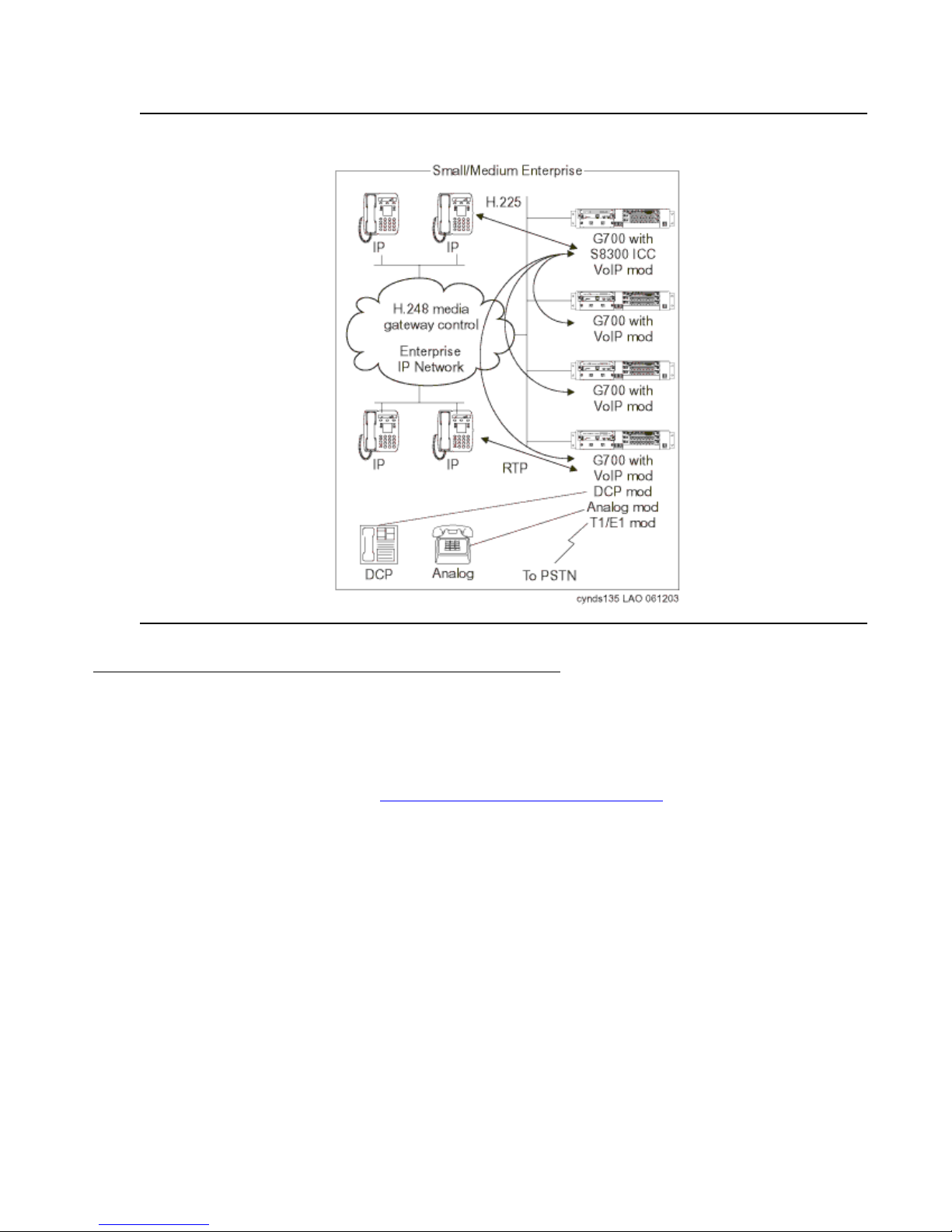
Figure 26: An S8300/G700/G350 system
Greenfield configurations
Medium-to-large enterprise solutions
S8700 / G650 IP-Connect
The S8700 IP-Connect system (Figure 27: S8700 IP-Connect system on page 80) is a scalable
solution that supports up to 64 G650 Media Gateways, each of which house up to four
rack-mounted cabinets. This solution can support up to 12,000 IP stations. The S8700 series
Media Servers can be networked with other systems through IP or circuit-switched trunks to
provide for significantly larger telephony networks. The control link between the Media Servers
and the Media Gateways traverses the enterpri se IP network. Al l G650 Media Gateways requi re
IPSI circuit packs to provide the Gateway’s control link. There is no traditional circuit switch
(Center S tage Switch) , and the med ia traf fic fl ow is ent irely th rough the enter prise data net work.
Each G650 has at least one Media Processor circuit pac k, which provides the gateway between
the TDM bus and the circuit pack’s Ethernet connection for the audio streams. Each G650 also
has at least one C-LAN, which provides H.323 signaling to IP endpoints.
Issue 3.4.1 June 2005 79
Page 80
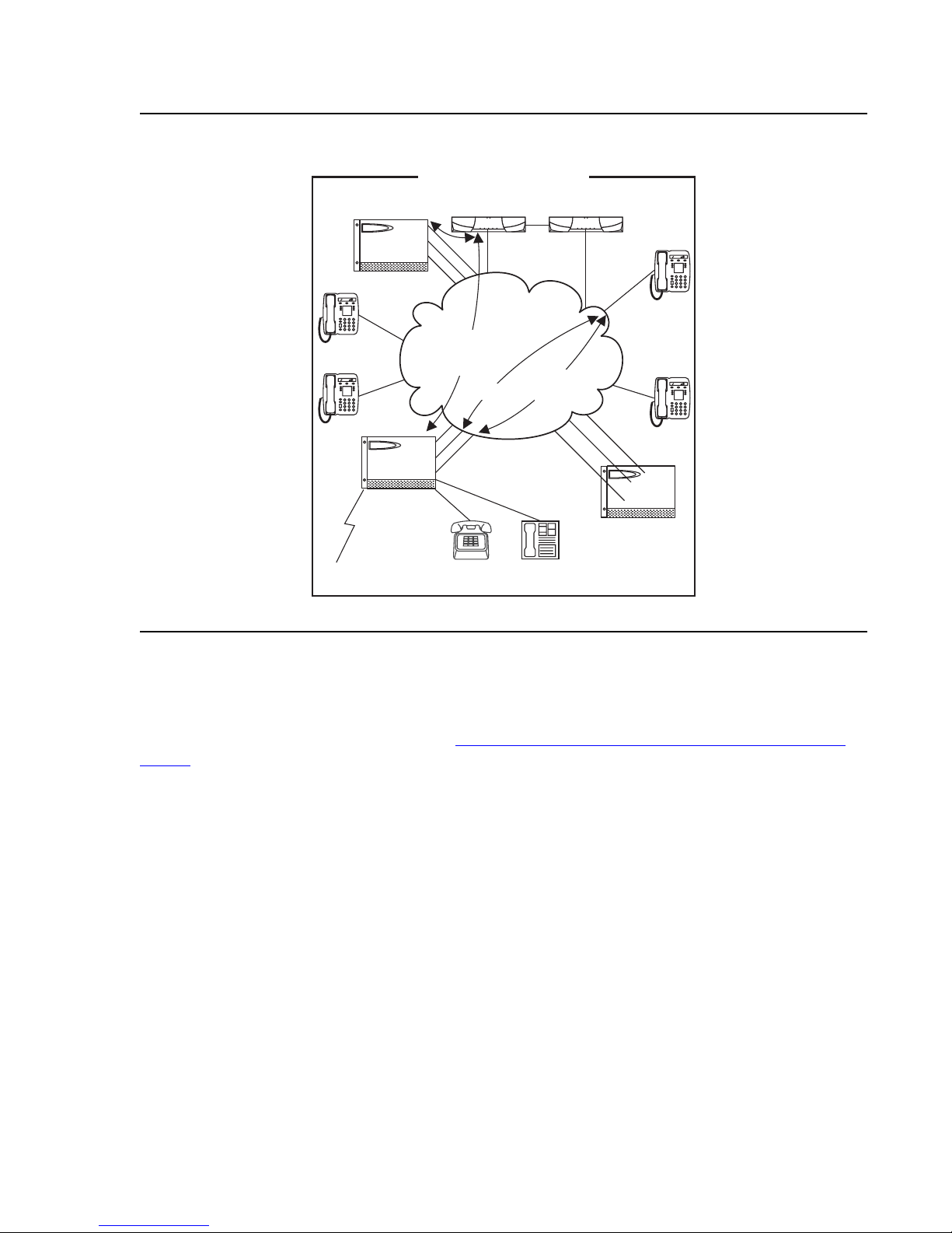
Greenfield deployment
Figure 27: S8700 IP-Connect system
G600/G650
IP
Medium/Large Enterprise
S8700 S8700
IPSI
C-LAN
MedPro
CCMS
over
TCP/IP
H.225
Enterprise
IP Network
RTP
Audio
IP
IP
IPSI
C-LAN
MedPro
G600/G650
To PSTN
Analog
DCP
S8700 IP-Connect with remote G700s or G350s
The IP-Connect solution can be expanded to support a remote of f ice with G700 or G350 Media
Gateways in addition to G650 Gateways (Figure 28: S8700 IP-Connect with remote G700 or
G350s on page 81). This solution is designed for enterprises that require a high number of IP
stations, but a low number of PSTN or traditional circuit-switched connections. The S8700
series Media Server is the call control ler that communicates with the G700 or G350 Gateways
through the C-LAN. In t his confi gurati on, the C- LAN cir cuit p ac k act s as t he fron t- end proces sor
for both the G700/G350 Media Gateways and IP endpoints.
IP
IPSI
C-LAN
MedPro
G600/G650
cynds136 KLC 121003
80 Avaya Application Solutions IP Telephony Deployment Guide
Page 81
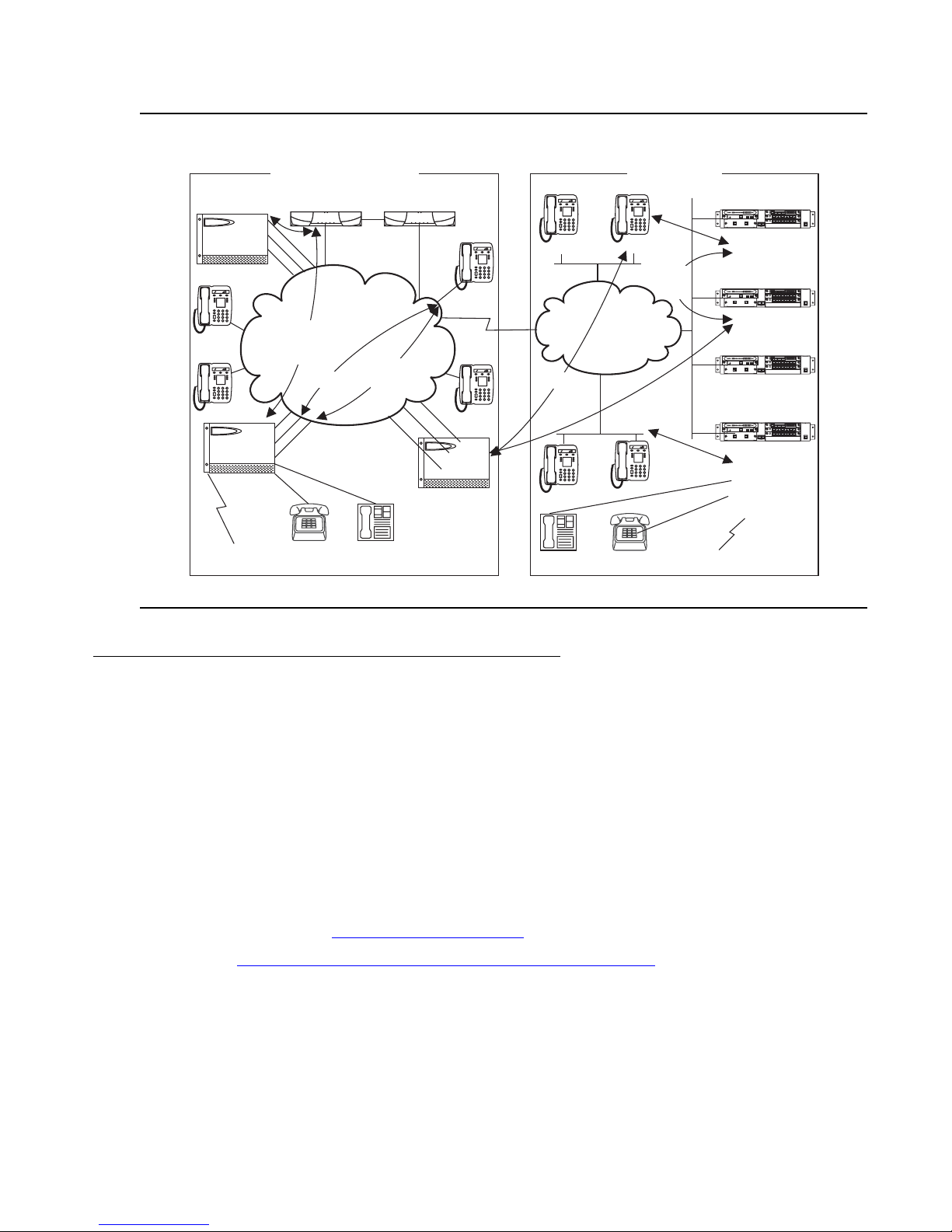
Figure 28: S8700 IP-Connect with remote G700 or G350s
ALM
TST
ACT
ALM
TST
ACT
ALM
TST
ACT
OKTO
SHUTDOWN
SERVICES
USB1
USB2
E1/T1
EIA 530A DCE
ALM
TST
ACT
SIG
ALM
TST
ACT
ALM
TST
ACT
ALM
TST
ACT
OKTO
SHUTDOWN
SERVICES
USB1
USB2
E1/T1
EIA 530A DCE
ALM
TST
ACT
SIG
ALM
TST
ACT
ALM
TST
ACT
ALM
TST
ACT
OKTO
SHUTDOWN
SERVICES
USB1
USB2
E1/T1
EIA 530A DCE
ALM
TST
ACT
SIG
ALM
TST
ACT
ALM
TST
ACT
ALM
TST
ACT
OKTO
SHUTDOWN
SERVICES
USB1
USB2
E1/T1
EIA 530A DCE
ALM
TST
ACT
SIG
Greenfield configurations
C-LAN
MedPro
G650
IP
IP
C-LAN
MedPro
G650
To PSTN
Medium/Large Enterprise
S8700 S8700
IPSI
Enterprise
IP Network
CCMS
over
TCP/IP
H.225
IPSI
Analog
RTP
Audio
DCP
IPSI
C-LAN
MedPro
G650
IP
WAN
IP
Remote Office
Backup
H.225
IP
IP
Backup
H.248
IP
Network
H.225
H.248 Media Gatewaycontrol
RTP
IP
DCP
IP
Analog
ALM
TST
ACT
SHUTDOWN
OKTO
REMOVE
SERVICES
G700 with
S8300 LSP
VoIP mod
ALM
TST
ACT
SHUTDOWN
OKTO
REMOVE
SERVICES
ALM
TST
ACT
SHUTDOWN
OKTO
REMOVE
SERVICES
ALM
TST
ACT
SHUTDOWN
OKTO
REMOVE
SERVICES
G700 with
VoIP mod
DCP mod
Analog mod
T1/E1 mod
To PSTN
cynds137 LAO 101104
USB1
USB2
USB1
USB2
G350
USB1
USB2
G350
USB1
USB2
ALM
TST
ACT
SIG
ALM
TST
ACT
ALM
TST
ACT
ALM
TST
ACT
SIG
ALM
TST
ACT
ALM
TST
ACT
ALM
TST
ACT
SIG
ALM
TST
ACT
ALM
TST
ACT
ALM
TST
ACT
SIG
ALM
TST
ACT
ALM
TST
ACT
E1/T1
1 2 3 4 5 6 87
1 2 3 4 5 6 87
E1/T1
1 2 3 4 5 6 87
1 2 3 4 5 6 87
E1/T1
1 2 3 4 5 6 87
1 2 3 4 5 6 87
E1/T1
1 2 3 4 5 6 87
1 2 3 4 5 6 87
EISO EMSM EOSI
EIA 530A DCE
EISO EMSM EOSI
EIA 530A DCE
EISO EMSM EOSI
EIA 530A DCE
EISO EMSM EOSI
EIA 530A DCE
Required circuit packs for S8700 configuration
The circuit packs that are required for IP Telephony in a Communication Manager system
include:
● TN2312 IP Server Interface (IPSI) for Port Network control
● TN799 Control LAN (C-LAN) for signaling and TCP/IP socket t ermination
● TN2302 Media Processor (MedPro) for the media flow
These circuit packs can reside in the CMC1, SCC1, MCC1, or G650 Media Gateways in
widely-distributed locations.
The signaling connectivity path between the endpoint and the servers in the S8700
configuration is shown in Figure 31: Signaling flow
on page 83.
As shown in Figure 29: Signaling path (S8700 / G650 configuration)
Telephone sends all IP Telephony signaling traffic to the C-LAN. The C-LAN multiplexes IP
Telephone signaling messages, and sends them to the S8700 server through the IPSI.
on page 82, an IP
Issue 3.4.1 June 2005 81
Page 82
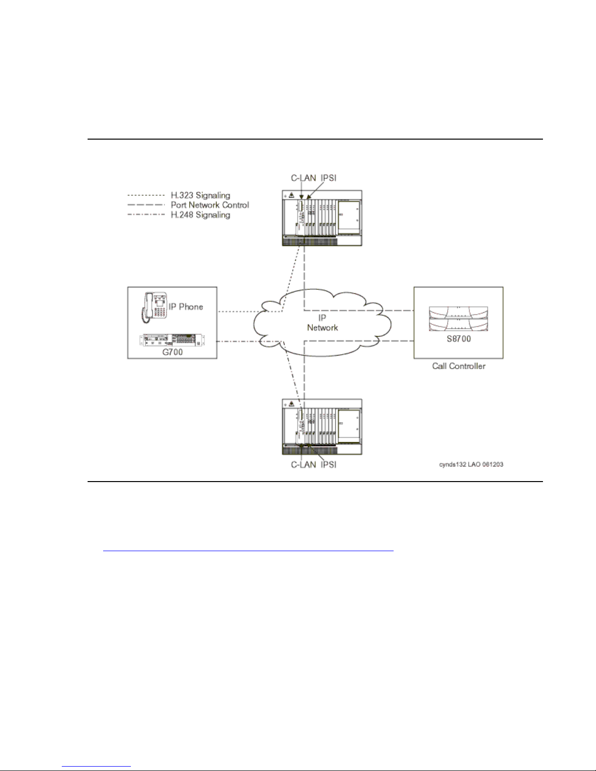
Greenfield deployment
Note:
In an S8300 configuration, a C-LAN circuit pac k is not needed. All signaling traffic is sent
directly to the S8300 Ethernet interface. The S8300 Server performs all C-LAN functions
natively. The connectivity between the endpoint and the server is:
Endpoint
⇔ IP network ⇔ S8300 Media Server
Figure 29: Signaling path (S8700 / G650 configuration)
Note: In the IP-Connect S8700 / G650 configuration each Port Network has an IPSI
circuit pack.
As Figure 30: Media flow path (S8700 IP-Connect configuration)
Telephone sends all media streams to the MedPro. Once a call is established, if th e remote
endpoint is another IP Telephone, the media stream might shuffle (be redirected to the other
endpoint) without requiring MedPro resources. Media Processors are also used to transport
media streams in IP tie trunks.
82 Avaya Application Solutions IP Telephony Deployment Guide
on page 83 shows, an IP
Page 83
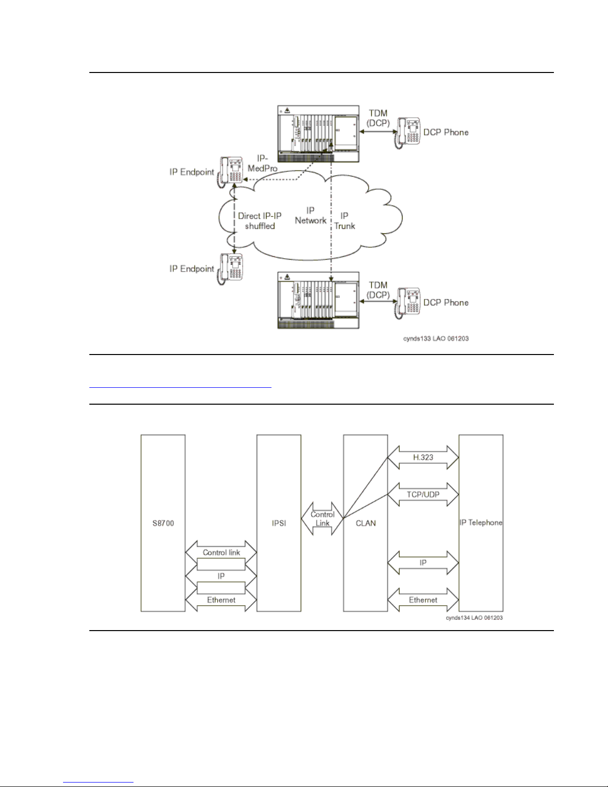
Figure 30: Media flow path (S8700 IP-Connect configuration)
Greenfield configurations
For detailed characteristics of the IPSI, C-LAN, and Media Processor circuit packs, see the
Avaya Application Solu tions platforms
chapter.
Figure 31: Signaling flow
Issue 3.4.1 June 2005 83
Page 84

Greenfield deployment
Communication devices
Avaya station s incl ude IP Telephones and IP Softphones. Avaya also supports IP trunks. In
addition, all the Media Gateways support traditional terminals, such as analog, BRI, and DCP
telephones. For detailed descriptions of Avaya IP Telephony endpoints, see the Terminals
chapter.
84 Avaya Application Solutions IP Telephony Deployment Guide
Page 85
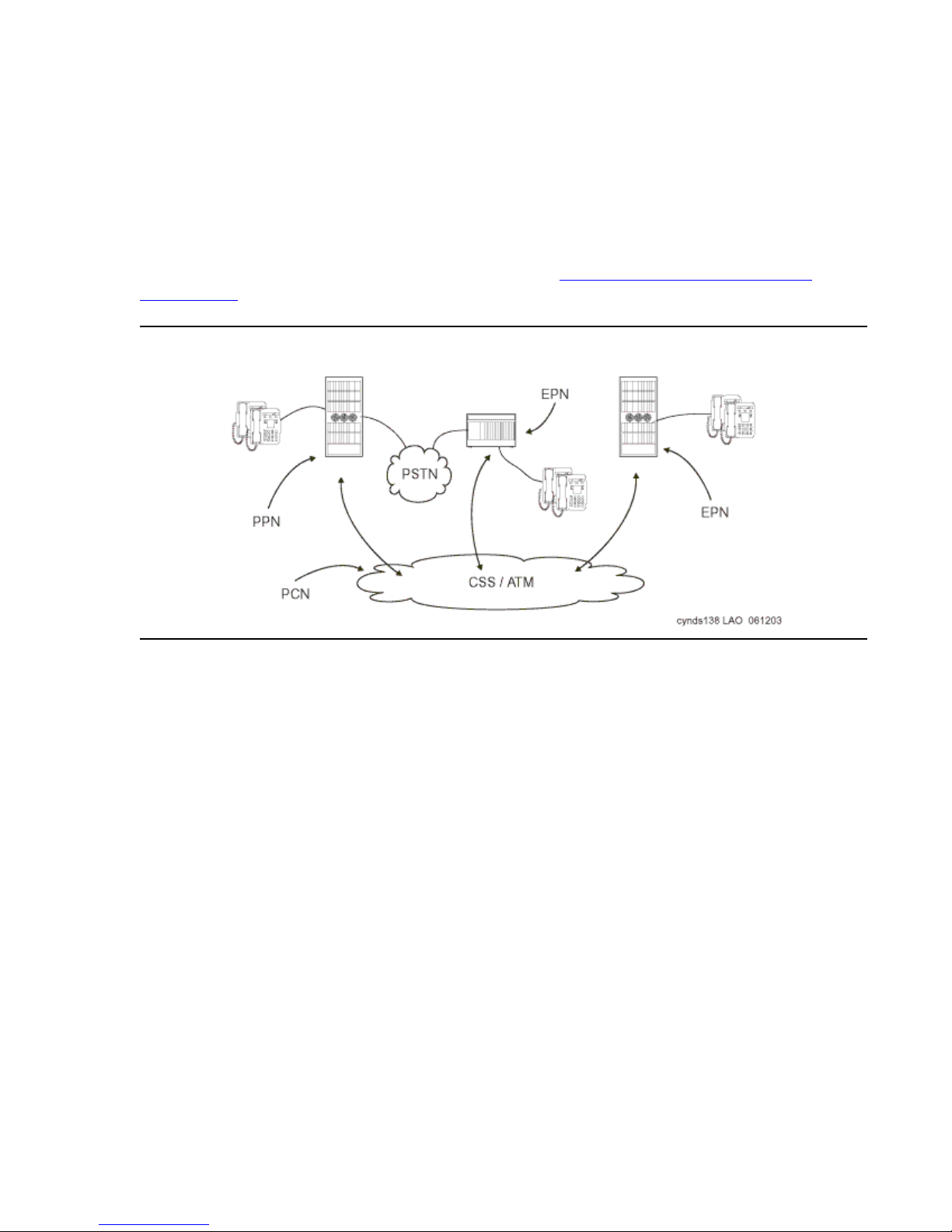
Evolution from circuit-switched to IP
The Avaya DEFINITY® Enterprise Communications Server G3r has been the flagship product
in the DEFINITY family of communications servers . As technolog y changed, A vaya was able to
leverage the rapid advances in microprocessor technology to increase the capacity and
processing power of the traditional DEFINITY platform (Figure 32: Traditional DEFINITY
configuration) to benefit our customers.
Figure 32: Traditional DEFINITY configuration
Avaya also has the object ive to protect our customers’ communi cations invest ment in the Av aya
DEFINITY platform by helping our customers leverage their existing investments in Avaya
solutions. Upgrading allows a customer to make a smooth transi tion to IP Telephony technology
without sacrificing the features or reliability of their current DEFINITY. A customer can make
small incremental investme nts to move from the circuit-switched world to a full IP PBX while
retaining their investment in TDM-base d equipment and connections. On the end point s, movi ng
to IP Telephony allows simplified moves, adds, and changes. It also simpli fies the building
wiring plan by sharing one Ethernet conne ction with bot h the IP Telephone and the desktop PC.
It also adds IP mobility wh ile r eta ini ng the r ich set of DEFI NITY feat ures . For bot h IP Telephone
and traditional circui t-switched t elephone users, mi grating to I P Telephony offers t he opportunity
to bypass tolls, and route traditionally metered long-distance calls across an unmetered IP
network instead, saving operational costs.
With the S8700 Multi-Connect solution, Avaya is delivering a high-capacit y server and a
migration path from DEFINITY. The S8700 Media Server uses an industry-standard Linux
operating system on an industry-standard server, which enables all endpoints to use
Communication Manager. This solution allows customers to migrate to IP Telephony and to a
higher performance processor without sacrificing the reliability of the G3r platform.
Issue 3.4.1 June 2005 85
Page 86

Evolution from circuit-switched to IP
There are three stages to upgrading fr om a DEFINITY G3r to an A vaya Communication
Manager IP PBX:
1. Replace the G3r processor with industry-standard S8700 servers.
2. Add IP circuit packs (C-LAN and MedPro) to support IP endpoints.
3. Consolidate multiple systems into a single system to simplify administration. Support
network or processor failure conditions with LSPs deployed at remote sites.
Step s 1 and 2 can be reversed. The next five diagrams show the migr ation from circuit- switched
DEFINITY to an IP-enabled S8700 Multi-Connect system with serve r consol idation and LSP
survivability at a remote site.
Migration from DEFINITY
Server R to S8700 Multi-Connect
Phase 1: Processor replacement
This section explains how an existing non-IP Avaya Communication Manager PBX can evolve
to an IP Telephony-based solution. We will examine the case of a n existing syst em that is based
on the traditional PPN/EPN architecture, which will be appli cable to all the G3 platforms.
When designing S8700 Multi-Connect systems, the call control networ k must be a nonrouted
private network that is disconnected fro m the internal IP network of the enterprise. The
equipment for this pri vate network is provided as part of the S8700 Multi-Connect so lution. See
Voice quality network requirements
support IP Telephony.
The S8700 Media Server controls Media Gateways in a dif fer ent manner than DEFINITY
controlled Port Networks. With DEFINITY, the control path signaling shared the same transport
media as the bearer channels. In a Multi-Connect system, call control signaling is established
from the S8700 Media Server over an Ethernet connection to the TN 2312 IP Server Inte rface
(IPSI) in the IPSI-connected Media Gateway. Non-IPSI connected Port Networks get their
control information from the servers through the Center Stage Switch to one of the Port
Networks that does contain an IPSI. An IPSI can support up to five Port Networks.
The full migration from a G3r to an S8700 server Mult i-Connect system, with traditional or ATM
center stage, involves the following simplified steps:
1. Decide which EPNs are to be IPSI connected, and replace processor compl exes with I PSIs .
2. Install servers.
for more information on setting up an IP network that can
3. Install Ethernet switches.
86 Avaya Application Solutions IP Telephony Deployment Guide
Page 87
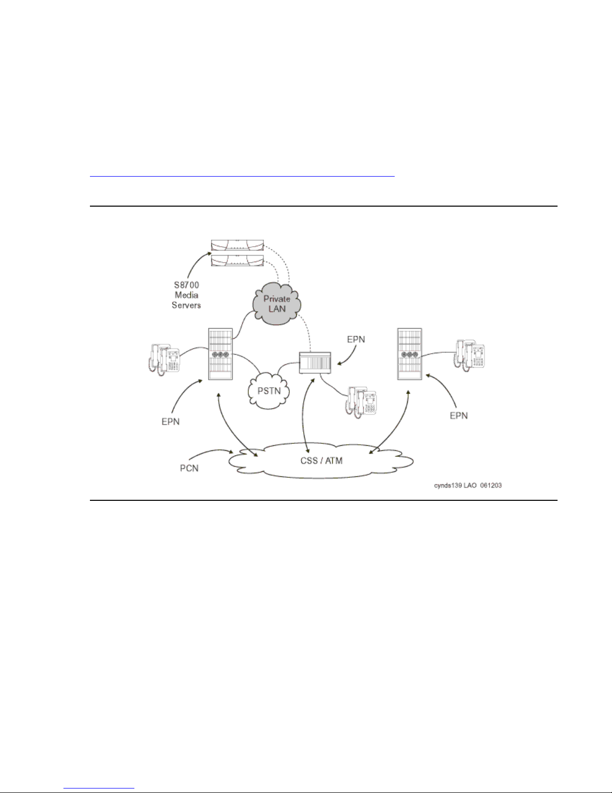
Migration from DEFINITY Server R to S8700 Multi-Connect
Note:
4. Install UPS units.
5. For IPSI-connected port networks, upgrade each EPN.
6. Connect the duplication links.
7. Connect the servers and the IPSIs to the control LAN.
8. Sequentially bring up the duplicated servers.
Figure 33: S8700 Media Servers (Multi-Connect configuration)
shows the completion of Phase
1, an S8700 Multi-Connect system that supports only traditional endpoints.
Figure 33: S8700 Media Servers (Multi-Connect configuration)
Note: In the traditional PBX system, signaling and bearer traffic for all calls connect s
through the TDM buses within Port Networks and the ATM or traditional center
stage
Issue 3.4.1 June 2005 87
Page 88
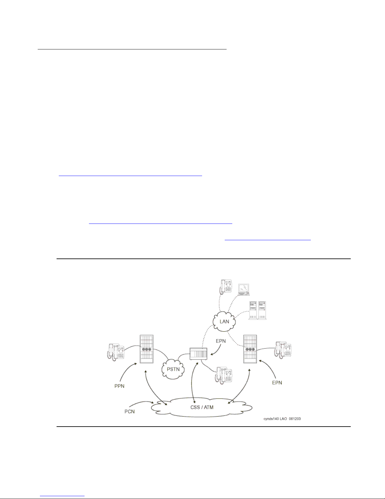
Evolution from circuit-switched to IP
Note:
Phase 2: IP-enable the Port Networks to support IP endpoints
Port Networks, with the addition of IP enabling circuit packs, are able to serve as Media
Gateways, representing the integration of IP and TDM telephony.
IP-enabling the existing system incrementally for IP endpoint support requires only two circuit
packs:
● TN799DP Control-LAN (C-LAN) for IP call signaling
● TN2602AP Media Resource 320 and TN2302AP Media Interface (MedPro) for IP audio
media processing, including media streams that are intended for IP Softphones and IP
Telephones
Signaling and bearer communic ation can c onnect through bot h the tradit ional TDM/center s tage
route and the IP network infrastructure. This gentle migration to IP Telephony
(Figure 34: IP-enabled DEFINITY configuration
non-IP system, while simultaneously enabling all new IP endpoints to fully access all the
Communication Manager features.
) might have minimal impact on an existing,
Note: If Phase 2 is implemented before Phase 1, the system will resemble
Figure 34: IP-enabled DEFINITY configuration
. Also, a system that implements
Phase 2 but not Phase 1 cannot support as many IP endpoints as a system that
implements both Phase 1 and Phase 2 (see DEFINITY Servers R and SI
page 71).
Figure 34: IP-enabled DEFINITY configuration
on
88 Avaya Application Solutions IP Telephony Deployment Guide
Page 89
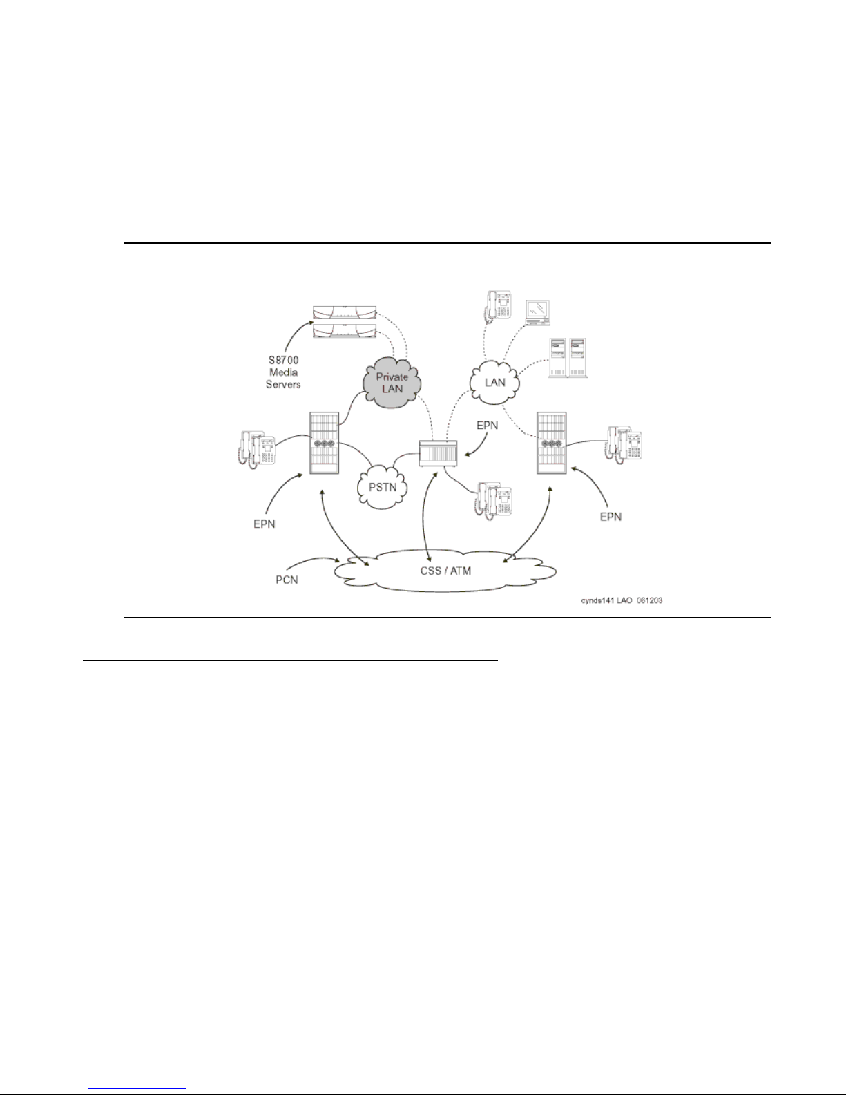
Migration from DEFINITY Server R to S8700 Multi-Connect
At this stage, the media fl ow between two IP end points can be “shuff led.” That is , the media flow
proceeds directly between both endpoints without requiring Media Processor resources.
Shuffling may be used across mul tiple s ites or multi ple A vaya swi tches. Lik ewise, calls bet ween
an IP endpoint at one site a nd a circuit -switched end point at another site can be s huf fled so tha t
the media stream flows between the IP Telephone and the Media Processor circuit pack in the
Port Network that is connected to the circuit-switched endpoint. By using the IP network to the
greatest extent possible, enterprises can minimize the use of expensive circuit-switched trunks.
Figure 35: IP-enabling the S8700 Multi-Connect configuration
Phase 3: Server consolidation
Traditionally, some enterprises have elected to use multiple DEFINITY systems at remot e sites
to protect against a circuit failure on the center stage network bringing down an entire remote
site. With the decision to run multip le servers came the need for additional administrative
resources and a more complex dial plan. Today, through the use of IP Telephony technology
and the enhanced processing ca pabilities of the S8700 Media Servers, Avaya has a solution to
consolidate smaller remote DEFINITY servers, such as ProLogix or DEFINITY ONE into an
S8700 Multi-Connect system, while mainta ining remote site survivability in the event of a
network or processor failure. By consolidating multiple DEFINITY servers into one S8700
system, an enterprise can realize cost savings in simplified administration and a simplified dial
plan. With support for up to 36, 000 endpo ints, the S8700 syst em has the scalabili ty to support a
remote site’s server consolidation.
Issue 3.4.1 June 2005 89
Page 90
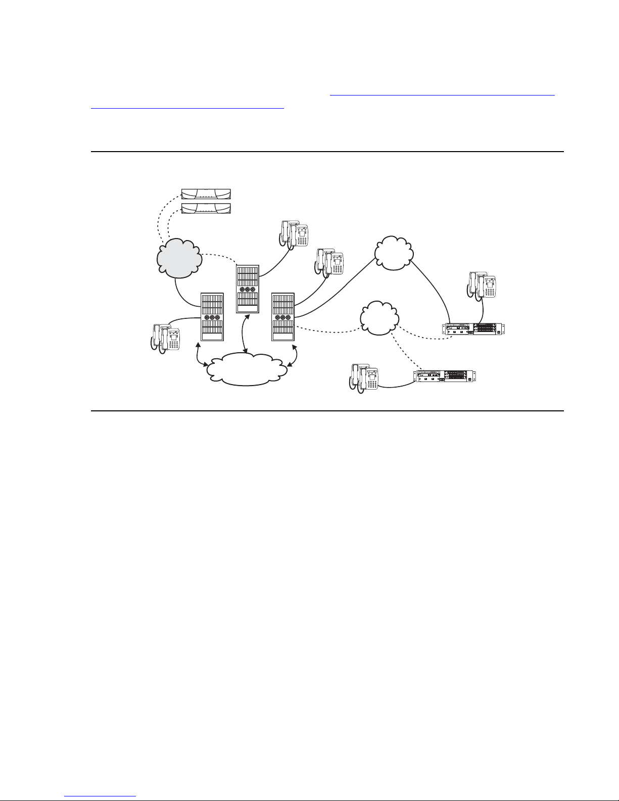
Evolution from circuit-switched to IP
ALM
TST
ACT
ALM
TST
ACT
ALM
TST
ACT
OKTO
SHUTDOWN
USB1
USB2
EIA 530A DCE
ALM
TST
ACT
SIG
SI
ALM
TST
ACT
ALM
TST
ACT
ALM
TST
ACT
OKTO
USB1
USB2
EIA 530A DCE
ALM
TST
ACT
SIG
Consolidating remote site servers into an S8700 system requires a G700 or G350 Media
Gateway with an S8300 Local Spare Processor (Figure 36: S8700 / G700 / G350 system with
S8300 as Local Sp are Processor (LSP)). In the event of a network or processor failur e, the
S8300 server takes over acti ve call processing and gateway and endpoint management for the
remote site, allowing continued operati on with no loss of features until the outage is repaired.
Figure 36: S8700 / G700 / G350 system with S8300 as Local Spare Processor (LSP)
Private
PSTN
LAN
LAN
ALM
TST
ACT
OKTO
REMOVE
EISO EMSM EOSI
ALM
TST
ACT
SIG
E1/T1 EIA 530A DCE
ALM
TST
ACT
SHUTDOWN
SERVICES USB1
USB2
1 2 3 4 5 6 87
ALM
TST
ACT
1 2 3 4 5 6 87
G350/LSP
CSS / ATM
cynds142 KLC 121003
ALM
TST
ACT
SHUTDOWN
OKTO
REMOVE
USB2
SERVICES USB1
G700/LSP
TST
ACT
SIG
E1/T1 EIA 530A DCE
ALM
TST
ACT
1 2 3 4 5 6 87
ALM
TST
ACT
1 2 3 4 5 6 87
EIEISO EMSM EOSI
ALM
Because the G700 and G350 rely on IP Telephony technology, this option is especially
attractive to customers who decide to use a majority of IP endpoints at the remote site. This
solution will, however, continue to support analog endpoint s and DCP endpo ints. Analog trunks
and ISDN trunks are also supported. To decrease operational expenses, the circuit-switched
trunks back to the main site can be replaced with IP trunks.
90 Avaya Application Solutions IP Telephony Deployment Guide
Page 91

Call processing
This chapter explains the features, the strengths, and the architecture of Communication
Manager call processing.
Communication Manager capabilities
This section lists and explains the major f eatures of Avaya Communication Manager that are
over and above traditional PBX features:
● Terminal mobility
● User login
● IP Softphone
● Analog terminal
This chapter emphasizes the call processing components of Communication Manager and its
architecture, and briefly discusses IP-related applications in the areas of teleph ony,
convergence, networking and call routing, mobility, telecommuting, and remote office. This
chapter is not an exhaustive resource for Communication Manager features.
Communication Manager operates on the Avaya Media Servers, and on the existing family of
DEFINITY servers. Communication Manager seeks to solve business challenges by powering
voice communications and integrating with value-added applicat ions. Communication Manager
provides user and system management functionality, intelligent call routing, application
integration and extensibility, and Enterprise Communications networking.
For more information on Communication Manager, see:
● Avaya Communication Manager Feature List contains details about the full capabilitie s of
Communication Manager (more than 700 features) by releas e, application area, or both:
- Avaya U.S. Business Partners : https://www.avaya.com/doc/gpp/public/pss/category/cs/
eclips/multivantage_software/index.html
● Overview for Avaya Communication Manager , 555-23 3-767, cont ains descr iptions of each
feature.
● Highlights of Avaya Communication Manager, 555-233-778, provides a delta view of new
features in Communication Manager Release 1.1 and Release 1.2.
Both of these documents are available on the Avaya Support web site.
Issue 3.4.1 June 2005 91
Page 92

Call processing
Voice and multimedia networking
Intelligent networking and call routing
With Avaya Communication Manager, servers can use IP trunks across an IP network to
communicate between switches without the need for dedicated leased lines. With
Communication Manager, IP trunks can use Distributed Communication Services (DCS+) or
QSIG Services to extend feature transparency, centralized voice mail, centralized attendant
service, call center applications, and enhanced call routing across IP trunks.
IP Port Network / Media Gateway connectivity
IP PNC allows S8700 Media Servers and G650 Media Gateways to be connected over IP
networks. Avaya Communication Manager uses a p ropr ietary method to package voice and
signaling messages over IP. This method allows deployment of communications systems
throughout a customer’s data network.
H.248 Media Gateway control
Communication Manager uses the standards-based H.248 media gateway control protocol to
perform call control of Avay a G700 and G350 Media Gateways. H.248 defines a framework of
call control signaling between the intelligent Media Servers and multiple Media Gateways.
H.248 controls both IP (H.323) and non-IP connections in to a media gateway . H.248 has been
extended by Avaya to also tunnel proprietary CCMS messages, to allow for enhanced call
handling.
Call Processing
Communication Manager gatekeepers
a gatekeeper is an H.323 entity on the network that provides address tr anslation and controls
access to the network for H.323 endpoints. For Communication Manager platforms, these are
the Avaya S8300 and S8700 Media Servers through the C-LAN circuit packs. H.323 RAS
(Registration, Admission, and S tat us) Protocol messages are exchanged between them and the
IP endpoints for the endpoint registration.
92 Avaya Application Solutions IP Telephony Deployment Guide
Page 93
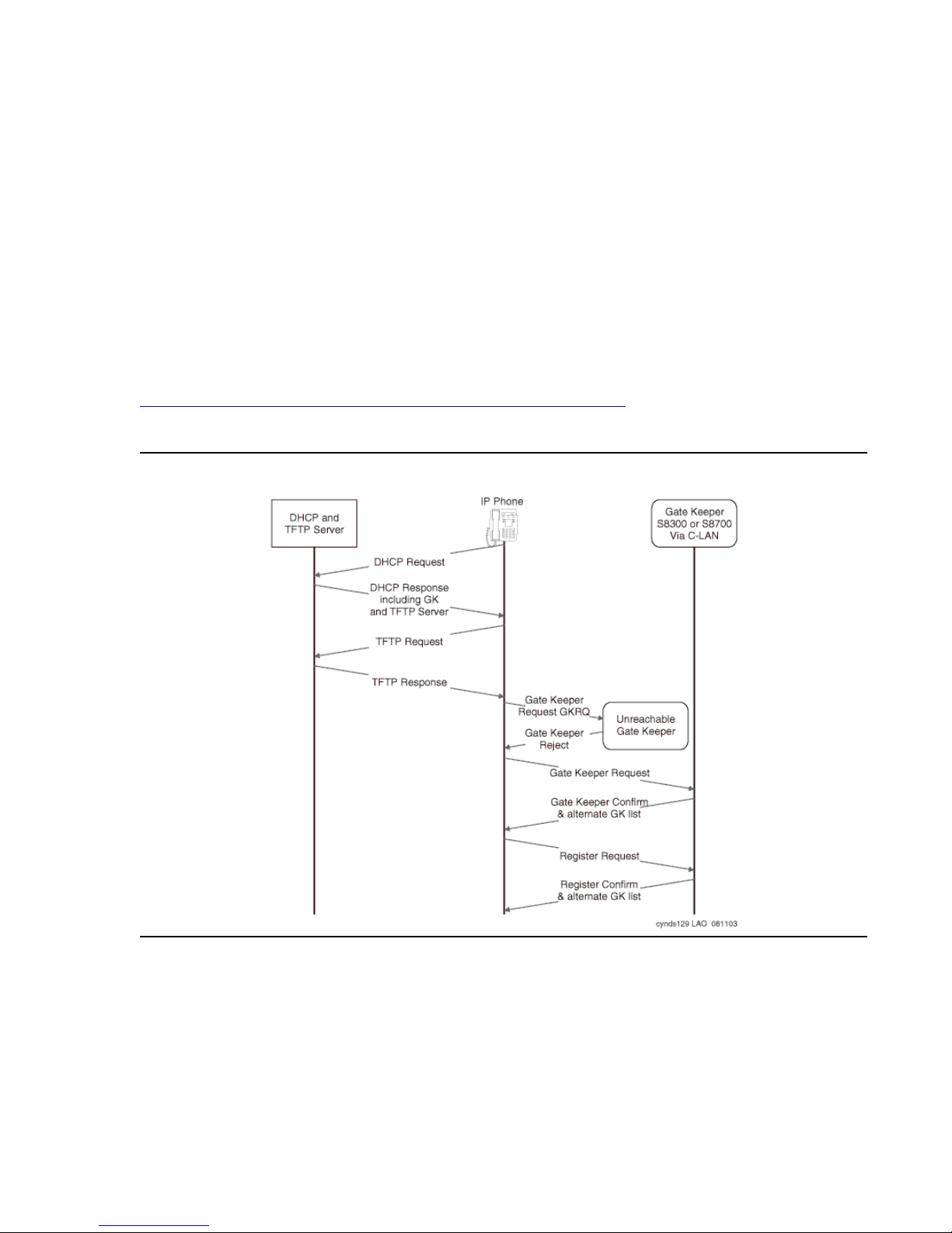
All IP endpoint s (IP Sof tphone s, IP agents, and IP Telephones) H.323 voice appli cat ions sh ould
register with an Avaya gatekeeper befor e any calls are attempted. Communication Manager
enforces call signaling (Q.931) and call contr ol (H.245) channels from endpoi nts to terminat e on
the gatekeeper. This allows Communication Manager to provide many of its calling f eatures to
H.323 calls.
Registration and alternate gatekeeper list
The RAS protocol is used by the IP endpoint to discover and register with the Communication
Manager gatekeeper. The discovery mechanism uses unicast IP facilities.
When registration with the original gatekeeper (C-LAN or S8300) IP address is successful, the
switch sends back the IP addresses of all the C-LANs (or LSPs) i n the IP Telephone’s network
region. These addresses are used if the call signaling to the ori ginal C-LAN circuit pack fails.
Figure 37: Discovery and registration process to the gatekeeper
process.
Figure 37: Discovery and registration process to the gatekeeper
Call Processing
shows the registration
Issue 3.4.1 June 2005 93
Page 94

Call processing
Call signaling
Communication Manager implements the gatekeeper rout ed call model of H.323. The
registration process that is described above allows the endpoint and the Communication
Manager gatekeeper to exchange addres ses to esta blish a TCP connecti on for a “cal l signaling”
channel (the H.323/H.225 channel). Once the TCP connection is established for call signaling,
the H.225.0/Q.931 signaling protocol is used over that connection to route the call and
exchange addresses necessary to establish a second TCP connection. This second TCP
connection is used for “media control” (the H.245 channel).
When Communication Manager chooses to route the media flow streams through the switch, it
selects and allocates available media processor resources, and sets the corresponding circuit
packs up to receive and send the media stream or streams from/to the endpoints using the
negotiated capabilities for each terminal. Each terminal is told to send its media stream or
streams to the appropriate Media Processor circuit pack. The switch connects the two media
streams, and thus completes the bearer path between the t erminals.
Media stream handling
Media processing
The basic functions of the TN2302 Media Processing (MedPro) circuit pack include:
● Taking media streams off the IP network, terminating RTP/UDP (adjusting for variable
delay in arrival rate), and converting them into PCM audio for transmission on the TDM
bus.
● Taking media streams from the TDM bus, encoding them with the proper codec, and
transmitting them as RTP packets to an IP endpoint.
● Originating and terminating an RTCP control channel f o r each media stream.
The particulars of the media conversion that is to be performed on each media stream are
controlled by Communication Manager. The Quality of Service (QoS) informati on obtained from
the RTCP channel is passed from the circuit pack to Communication Manager.
DTMF tone handling
The Media Processor circuit pack list ens for and detects DTMF tones coming from the TDM
bus, strips them out of the audio stream, and sends a message to the Media Server indicating
that it has done so. The Media Server in turn generates and sends the appropriate H.245 tone
message to the endpoint that is receiving the audio stream. The receiving endpoint then plays
the specified tone. Compressed codecs, such as G.729, generally do a poor job of passing
DTMF tones. By sending tones out of band, fidelity is maint a ined. This method is useful when
connecting to a voice mail or an integrated voice respo nse (IVR) system, where DTMF digits
are used to navigate through prompts.
94 Avaya Application Solutions IP Telephony Deployment Guide
Page 95

When this capability is used on an H.323 tie trunk b etween Commu nication Manager switches,
the switch that receiving the H.245 tone message plays the required tone onto all the ports
receiving the audio stream.
Media stream for audio conferencing
When calls between IP endpoints are conferenced, the media streams must be routed through
the MedPro circuit pack.
Communication Manager allows the audio streams from different parties to come into different
Media Processor circuit p acks. Each Media Proces sor sends its received signal to the TDM bus
in Pulse Code Modulation (PCM) format. All the other processors serving endpoints on the call
can then receive and sum the audio signals coming from all parti es, and send the resultant
composite audio stream to the IP parties that it supports.
Call Processing
Figure 38: MedPro support of a three-party audio conference
on page 96 provides an example
to show how the MedPro circuit pack is configured for a three-party H.323 audio conference
using G.729. This conference is conventional in that it uses TDM bus timeslots to al low each
party to listen to all of the other parties. However, a more efficient form of conferencing is
possible when all the parties are IP endpoi nts, where the audio streams are multiplexed dir ectly
on the Media Processor circuit pack, and no TDM timeslots are used. To establish the
configuration shown in Figure 38: MedPro support of a three-party audio conference
, the DSP
resources on the MedPro are allocated as needed to audio conferencing. Commu nication
Manager balances the available media processing resources, effectively sharing load among
multiple MedPros.
Issue 3.4.1 June 2005 95
Page 96
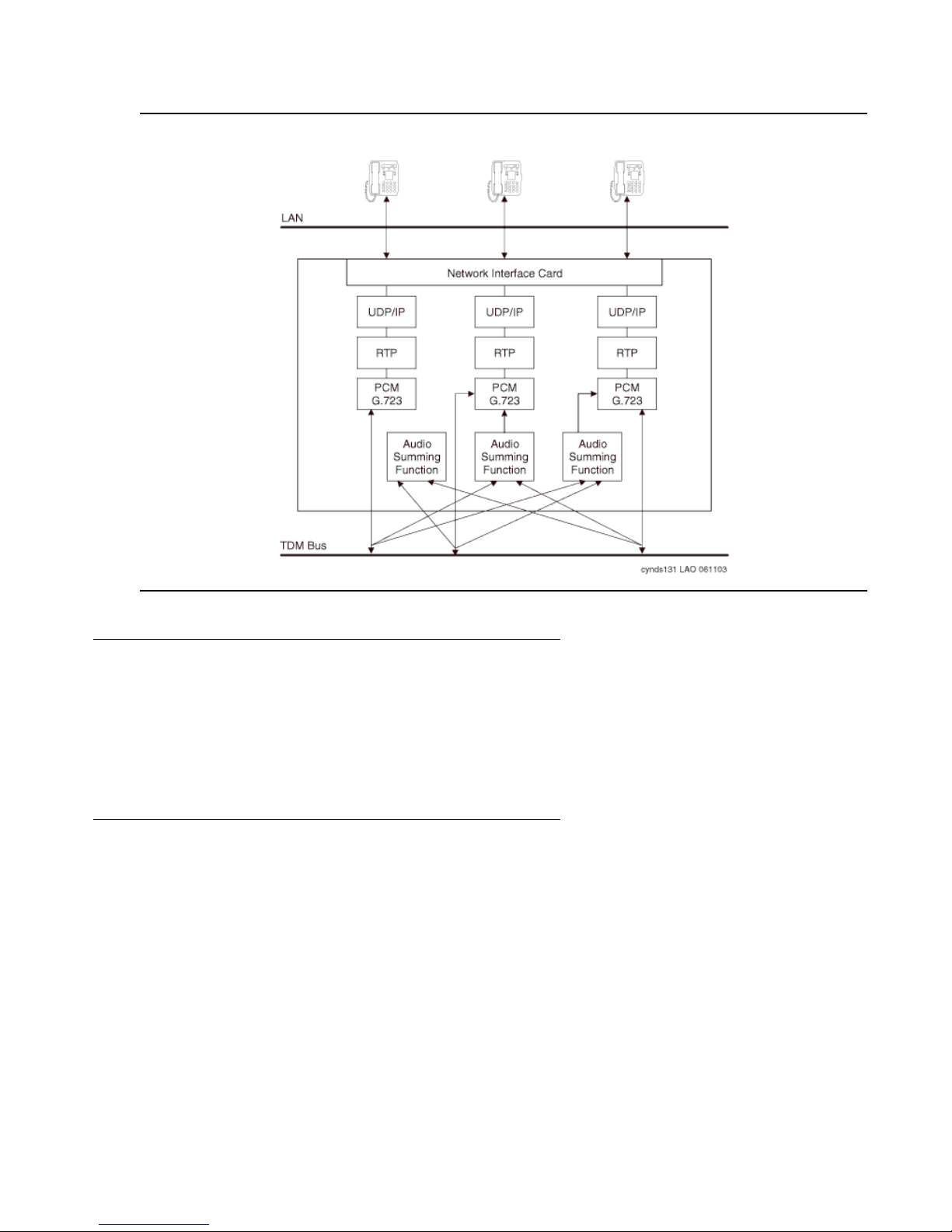
Call processing
Figure 38: MedPro support of a three-party audio conference
Separation of Bearer and Signaling (SBS)
In an Avaya IP Telephony system, call signaling and bearer traffic may be routed over sep arate
paths. This is useful for a remote branch office with only limited WAN bandwidth back to
headquarters. Call signaling traffic can be routed across the WAN, while bearer traffic is sent
over the PSTN.
Multi-location
Communication Manager 2.2 allows a Linux-based media server located in one country to
control gateways located across national borders and provide appropriate country-specific
tones and features. Specifically, these features include the following:
● A-law & Mu-law Companding
● Call Progress Tone Generation
● Loss Plan
● Analog line board parameters
96 Avaya Application Solutions IP Telephony Deployment Guide
Page 97

● Call Detail Recording
● R2-MFC (Multifrequency-Signaling) trunks
Multi-location functional ity is subject to the following limitations:
● 25 Countries
● R2-MFC: 8 signaling sets
● Additional Tone Generators (TN 2182 in Port Networks, built-in tone generators in Media
Gateways) are required to support country-specific tones
● No per-country alarms or traffic reports are available
● LSPs must be set to the same time zone as the server
● This feature is intended for IP-remoted gateways, not DS1-remoted Port Networks.
Modem/Fax/TTY over IP
In the past, many organizations have experienced problems transporting modem, fax, and TTY
tones over an IP Telephony network, regardless of vendor. Modems, faxes, and TTYs are very
sensitive to latency and jitter, and do not tolerate distortion induced through compression,
expansion, and transcoding. In order to overcome these difficulties, Avaya has enhanced its
modem, fax, and TTY-over-IP support in release 2.2.
Call Processing
There are two enhanced modes for supporting Modem-over- IP ( MoIP): p ass -throug h and rel ay.
Pass-through is essentially a best- effort transmission, and works by for cing the use of the G.71 1
(uncompressed) codec for the call. Re-transmission is governed by the application.
Pass-through mode is suited to LAN environments where both ends of a call are synchronized
using a common clock source. Relay, on the other hand, uses redu ndant pa cket t ransmission to
protect against packet loss. Because relay mode does not force the use of G.711, it requires
less bandwidth than pass-through, however requires more DSP resources. Relay is more
effective than pass-through across a WAN.
Avaya’ s TTYoIP support works by identifying TTY Baudot tones at the near- end Media
Processor, removing them from the voice path, and transporting them across the network in
RFC 2833 messages. The far-end Media Processor receives the RFC 2833 messages and
regenerates them for the far-end st ation. This feature is enabled by default on IP trunks and
inter-gateway calls, and is capable of toggling between text and voice modes.
Avaya’s support for modem, fax, and TTY over IP can be summarized as follows:
● TTY over IP continues to be supported
● Modem Pass-through is supported between Avaya gateways
● Modem Relay at 9.6K is supported between Avaya gateways
● Avaya supports sending multiple instances of the same packet
Redundant transmission mitigates the effects of packet loss, but requires additional bandwidth.
Issue 3.4.1 June 2005 97
Page 98

Call processing
Avaya’s modem, fax, and TTY over IP support is subject to the following limitations:
● QOS is required, even on LAN.
● Avoid MoIP where possible (especially over a WAN environment)
● Use circuit-based resources on the same gateway
● Use different classes of service and restrictions
● Use centralized modem pooling for larger communities
● Only one TDM-to-IP-to-TDM conversion is allowed
● Send duplicate streams, where practical
Table 16
summarizes Avaya’s fax, modem, and TTY options.
Table 16: Fax, Modem, and TTYoIP options
Fax
relay
Default, Avaya-propriet ary mode, inter operates with previ ous
releases
Pass-thru
Proprietary mode; uses more bandwidth, fewer DSP
resources
system ignores fax tones, call remains in administered codec
Default, system ignores modem tones, call remains in
Modem
off
off
administered codec
Avaya-proprietary mode, most reliable modem-over-IP mode
similar to Fax pass-thru
Default, 45.45 Baudot, interoperates with previous releases
50 Baudot
similar to Fax pass-thru
TTY
relay
pass-thru
US
UK
pass-thru
off
98 Avaya Application Solutions IP Telephony Deployment Guide
system ignores TTY tones, call remains in administered
codec
Page 99

IP-based trunks
In circuit switched networks, trunks provide the means to interconnect PBXs with each other
and to the PSTN. Connection to the public network allows PBX station users to call and be
called by terminals that are not pa rt of the PBX private network of the PBX. An analogous
arrangement exists in p a cket-switched IP networks.
H.323 trunks connect H.323 systems or gateways over IP networks, similar to circuit-switched
tie trunks. Similarly, SIP trunks connect SIP systems or gateways over IP networks.
A set of Communication Manager switches can each be attached to an IP network, and voice
and fax calls can flow between them in the usual manner except that the call signaling and
audio/fax streams are c arrie d over the IP net work. The si gnaling i s carri ed on a TCP c onnection
through the C-LAN circuit packs, and the audio and fax streams are carried between switches
through the Media Processor circuit p acks.
The benefits of using IP trunks include:
● Reducing long distance voice and fax expenses
● Facilitating global communications
IP-based trunks
● Providing a fully functional network with data and voic e
● Converging and optimizing networks by using the available network resources
IP trunk calls can be compressed to save network bandwid th. Repeated compression and
decompression (transcoding) results in a loss of data at each stage and degrades the final
quality of the signal. The maximum recommended number of compression cycles on a call is
three. Normal corporate voice calls or fax calls typically go through fewer than three
compression cycles.
IP (H.323 and SIP) trunks can also connect to other vendors’ compliant PBXs.
SIP trunk capac ities
Table 17 shows the maximum number of SIP trunks supported out of the total number of IP
trunks supported.
Table 17: SIP Trunk Capacities by Platform Configuration
Platform Configurat ion Maximum Number of SIP IP Trunks
S8700 Multi-Connect 1000 of 8000
S8700 IP-Connect 1000 of 4000
of the Total IP Trunks Supported
S8700/G700/G350/LSP 1000 of 8000
S8500 800 of 800
S8300/G700/G350 100 of 450
Issue 3.4.1 June 2005 99
Page 100

Call processing
IP tie trunks
IP tie trunks are used to connect switches to one another. When an IP trunk is used to
interconnect two switches, the trunk can also carry standard (QSIG) and proprietary (DCS+)
signaling for interswitch feature transparency. The location of each other node (switch) in the
network is administered, and node selecti on is based on the dial plan and call routing features
such as AAR/ARS.
H.323 or SIP tie trunks are administ ered as a new type of trunk group. Instead of admini stering
ports as members of the trunk group, only the number of channel s must be specified. Each
channel is analogous to a member trunk. In addition, an IP tie t runk can be made a member of a
signaling group so that a virtual D-channel can be administ e red and used to carry feature
transparency informati on.
Trunk signaling
Several variations of IP signali ng must be accommodated for the var iety of t runks suppor ted by
Communication Manager. These are specified as options in the trunk group administrat ion.
When the IP trunk is used as a tie trunk to another vendor’s switch, gateway, or gatekeeper,
Communication Manager sets up a separate TCP connectio n for each cal l.
SIP
SIP stands for Session Initiation Protoc ol, an end point -orien ted messaging st andar d defined by
the Internet Engineering Task Force (IETF). SIP is a text-based protocol, similar to HTTP and
SMTP, for initiating interactive communication sessions between users. Such sessions include
voice, video, instant messagi ng, interactive games, and virtual reality.
As implemented by Avaya for Communicati on Manager re lease 2 .0, SIP "trunk ing " func tional ity
will be available on any of the Linux-based media servers (S8300, S8500 or S8700). SIP
trunking allows Avaya Communication Manager to communicate with SIP endpoints and
gateways across an IP network. In addition, Avaya Communication Manager supports SIP
endpoints, including the Avaya 4602 SIP Telephone and Avaya IP Softphone Release 5. In
addition to its IP telephony capabilities, IP Softphone R5 will also include Instant Messaging
(IM) client software, which is a SIP-enabled appl ication that connects to the Avaya Converged
Communication Server for IM control.
100 Avaya Application Solutions IP Telephony Deployment Guide
 Loading...