

Page 1

DJH; Reviewed:
SPOC 06/18/2012
Solution & Interoperability Test Lab Application Notes
©2012 Avaya Inc. All Rights Reserved.
1 of 24
WLAN8180_ADVD
These Application Notes describe the steps to configure Avaya Wireless LAN Controller 8180
and Avaya 8120 Access Points to support Avaya A175 Desktop Video Devices in an 802.1X
enabled Avaya wireless network infrastructure. Avaya A175 Desktop Video Devices register
as SIP endpoints to Avaya Aura® Session Manager 6.2 via Avaya 8120 Access Points. 802.1X
authentication and WPA (WiFi Protected Access) are enabled on the wireless LAN to prevent
unauthorized access and provide encryption. The wireless configuration described in this
document also applies to other types of wireless endpoints such as Avaya Flare®
Communicator or Avaya Flare® Experience on iPad devices which will be described in future
Application Notes.
These Application Notes provide information for the setup, configuration, and verification of
the call flows tested on this solution. Information in these Application Notes has been obtained
through interoperability testing conducted at the Avaya Solution and Interoperability Test Lab.
Avaya Solution & Interoperability Test Lab
Configuring Avaya Wireless LAN Controller 8180 with
Avaya 8120 Access Points to support Avaya A175 Desktop
Video Devices using 802.1X Authentication – Issue 1.0
Abstract
Page 2

DJH; Reviewed:
SPOC 06/18/2012
Solution & Interoperability Test Lab Application Notes
©2012 Avaya Inc. All Rights Reserved.
2 of 24
WLAN8180_ADVD
1. Introduction
These Application Notes describe the steps to configure Avaya Wireless LAN Controller 8180
and Avaya 8120 Access Points to support Avaya A175 Desktop Video Devices in an 802.1X
enabled Avaya wireless network infrastructure. Avaya A175 Desktop Video Devices register as
SIP endpoints to Avaya Aura® Session Manager 6.2 via Avaya 8120 Access Points.
802.1X authentication and WPA (WiFi Protected Access) are enabled on the wireless LAN to
prevent unauthorized access and provide encryption. .
These Application Notes focus on the configuration of Avaya Wireless LAN Controller 8180
and Avaya A175 Desktop Video Devices to support wireless communication. Detailed
administration of other aspects of Avaya Aura® Communication Manager or Avaya Aura®
Session Manager will not be described. See the appropriate documentation listed in Section 12
for more information.
2. Interoperability Testing
Avaya A175 Desktop Video Devices successfully utilized Avaya 8100 Series wireless
communications infrastructure to place and receive telephone calls with other Avaya SIP
endpoints registered to Session Manager. All tests were performed manually.
2.1. Test Description and Coverage
Test cases included bi-directional calls between Avaya A175 Desktop Video Devices and other
Avaya endpoints, as well as traditional telephony operations and features such as extension
dialing, displays, hold/resume, transfer, conferencing, call forwarding, coverage to Avaya Aura®
Messaging.
2.2. Test Results and Observations
All test cases were successful. There were no issues observed during testing.
Page 3

DJH; Reviewed:
SPOC 06/18/2012
Solution & Interoperability Test Lab Application Notes
©2012 Avaya Inc. All Rights Reserved.
3 of 24
WLAN8180_ADVD
3. Reference Configuration
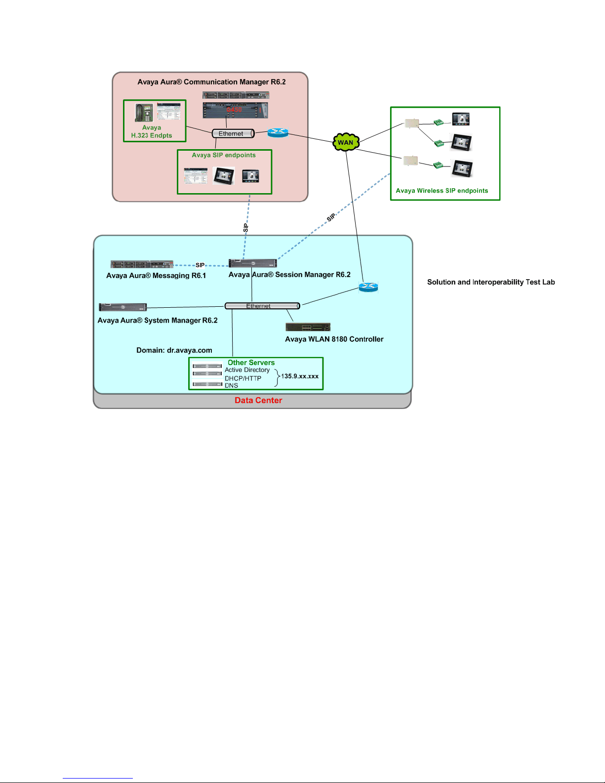
The reference configuration described throughout these Application Notes is shown in Figure 1.
To support wireless communication, several Avaya 8120 Access Points were deployed in the
sample configuration and registered to an Avaya Wireless LAN Controller 8180.
As shown in Figure 1, Avaya A175 Desktop Video Devices and other SIP endpoints utilize the
Session Manager User Registration feature and are supported by Communication Manager. For
the sample configuration, SIP users are not IP Multimedia Subsystem (IMS) users and
Communication Manager is configured as an Evolution Server in the Avaya Aura architecture.
When Communication Manager is configured as an Evolution Server, it applies both originationside and termination-side features in a single step. For more information regarding configuring
Communication Manager as an Evolution Server, see References [4] through [7] in Section 12.
Communication Manager is connected to Session Manager via a non-IMS SIP signaling group
and associated SIP trunk group.
Communication Manager also supports non-SIP endpoints such as Avaya 9600 Series IP
Deskphones and Avaya one-X® Communicator clients configured as H.323 endpoints.
Session Manager is managed by System Manager. For the sample configuration, Session
Manager and System Manager are running on separate Avaya S8800 Servers. Communication
Manager Evolution Server runs on an Avaya S8800 server with an Avaya G6450 Media
Gateway.
Note: IP addresses have been partially hidden in Figure 1 for security.
Page 4
DJH; Reviewed:
SPOC 06/18/2012
Solution & Interoperability Test Lab Application Notes
©2012 Avaya Inc. All Rights Reserved.
4 of 24
WLAN8180_ADVD
Figure 1: Avaya 8100 Series Wireless Network Configuration
Page 5

DJH; Reviewed:
SPOC 06/18/2012
Solution & Interoperability Test Lab Application Notes
©2012 Avaya Inc. All Rights Reserved.
5 of 24
WLAN8180_ADVD
4. Equipment and Software Validated
Component
Software Version
Avaya Aura® Session Manager on Avaya S8800
Server
Release 6.2
Build 6.2.0.1.01059009
Avaya Aura® System Manager on Avaya S8800
Server
Release 6.2
Version: 6.2.0.10.13835-6.2.10.2
Avaya Aura® Communication Manager
Evolution Server on Avaya S8800 Server with
Avaya G450 Media Gateway
Release 6.2
Version R16x.02.0.823.0-19402
Avaya A175 Desktop Video Device
FW: Release 6.1.1
version: SIP_A175_1_1_1_016002
Avaya Wireless LAN Controller 8180
Release 1.1, version v1.1.0.133
Avaya Wireless LAN 8120 Access Point
Release 1.1, version v1.1.0.133
The following equipment and software were used for the configuration provided:
5. Configure Avaya Aura® Communication Manager
There is no additional configuration required on Communication Manager to support wireless
endpoints. For details on configuring Communication Manager Servers, Gateways, or Endpoints,
see References [4] through [7] in Section 12 or consult other Administration and Configuration
documents for Communication Manager available on http://support.avaya.com.
6. Configure Avaya Aura® Session Manager
There is no additional configuration required on Session Manager to support wireless endpoints.
For details on configuring Session Manager to support registration of SIP endpoints, see
References [1] through [3] and [13] in Section 12.
Page 6

DJH; Reviewed:
SPOC 06/18/2012
Solution & Interoperability Test Lab Application Notes
©2012 Avaya Inc. All Rights Reserved.
6 of 24
WLAN8180_ADVD
7. Configure Avaya Wireless LAN Controller 8180
This section describes the steps needed to configure Access Points profiles and associated
network profiles on the Avaya Wireless LAN Controller 8180 to support wireless endpoints.
These instructions assume the Avaya Wireless LAN Controller 8180 is already installed and
configured as a controller capable of managing mobility domains. For information on how to
administer these aspects of Avaya Wireless LAN Controller 8180, see References [10] through
[12] in Section 12.
This section describes the administration of Avaya Wireless LAN Controller 8180 using a
Command Line Interface (CLI). The following administration steps will be described:
Verify Status of Avaya Wireless LAN Controller 8180.
Configure DHCP Server.
Configure Access Points.
Configure Mobility VLAN.
Configure Network Profile.
Configure Access Point Profile.
Synchronize Changes between Avaya Wireless LAN Controller 8180 and Access Points.
Verify Management Status of Access Points.
Page 7

DJH; Reviewed:
SPOC 06/18/2012
Solution & Interoperability Test Lab Application Notes
©2012 Avaya Inc. All Rights Reserved.
7 of 24
WLAN8180_ADVD
7.1. Verify Status of Avaya Wireless LAN Controller 8180
Step 1: Use the show wireless command to verify the Status of the Avaya Wireless LAN
Controller 8180 is “Enabled” as shown below.
WC8180#show wireless
Status : Enabled
Interface IP : 20.20.20.160
TCP/UDP base port : 61000
Step 2: Use the show wireless controller domain-membership command to verify the Avaya
Wireless LAN Controller 8180 has been configured as a Mobility Domain Controller (MDC).
Verify the status of the following fields as shown below.
Domain Role Verify “Active MDC” is displayed.
Domain Action Status Verify “Join Success” is displayed.
WC8180#show wireless controller domain-membership
Domain Name : AVAYA
Domain Role : Active MDC
Domain Action Status : Join Success
Action Failure Reason : None
Step 3: Use the show ip routing command to verify IP Routing has been “enabled”.
WC8180#show ip routing
IP Routing is enabled
IP ARP life time is 21600 seconds
WC8180#
Step 4: Use the show ip route command to verify the appropriate IP routes have been
configured on Avaya Wireless LAN Controller 8180.
In the sample configuration, the following IP Routes were configured where “20.20.20.1” is the
IP address of the network gateway.
WC8180#show ip route
=============================================================================
Ip Route
=============================================================================
DST MASK NEXT COST VLAN PORT PROT TYPE PRF
-----------------------------------------------------------------------------
0.0.0.0 0.0.0.0 20.20.20.1 1 20 2 S IB 5
20.20.20.0 255.255.255.0 20.20.20.160 1 20 ---- C DB 0
Total Routes: 2
----------------------------------------------------------------------------TYPE Legend:
I=Indirect Route, D=Direct Route, A=Alternative Route, B=Best Route, E=Ecmp
Page 8
DJH; Reviewed:
SPOC 06/18/2012
Solution & Interoperability Test Lab Application Notes
©2012 Avaya Inc. All Rights Reserved.
8 of 24
WLAN8180_ADVD
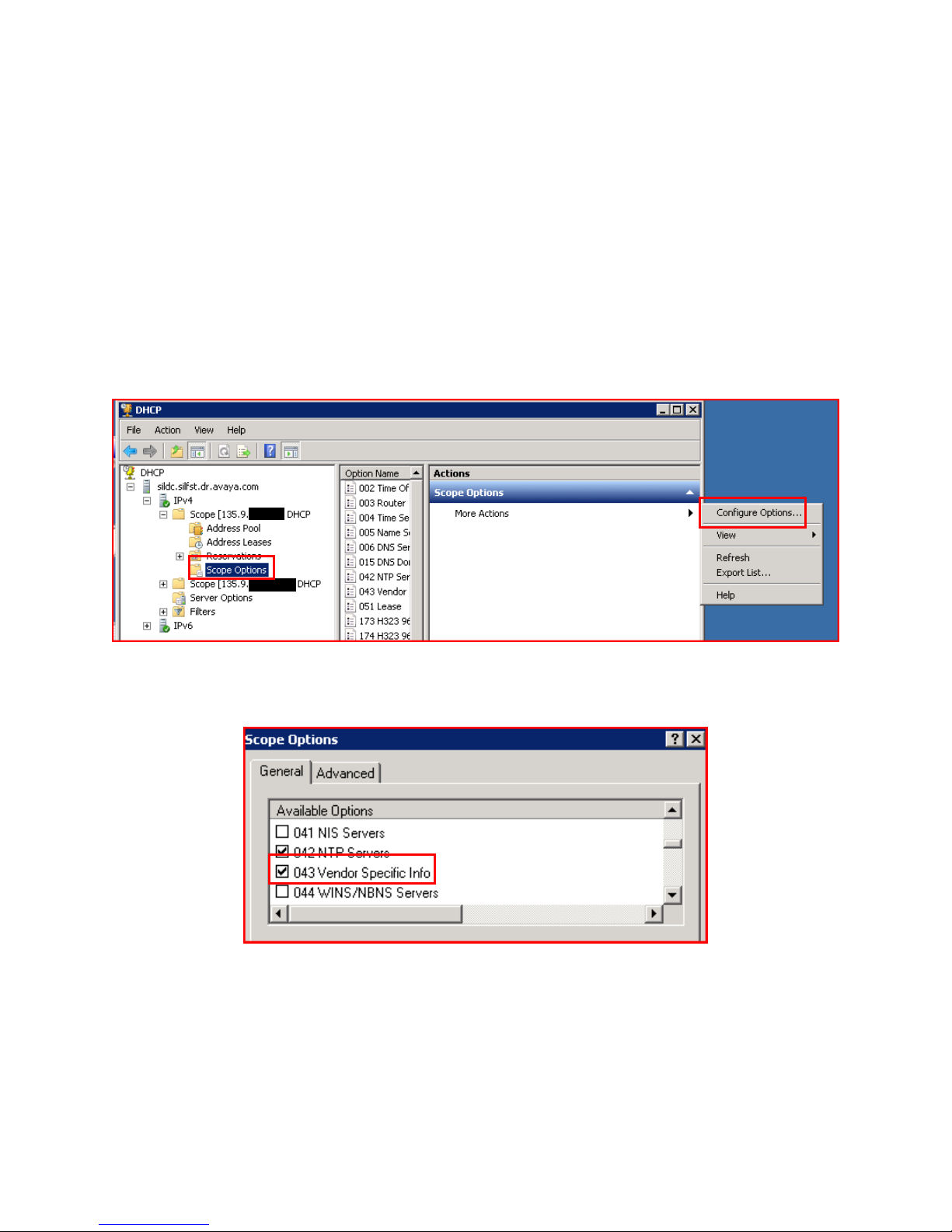
7.2. Configure DHCP Server
Since Avaya 8120 Access Points do not provide mechanism for manually configuring the IP
address of the Avaya Wireless LAN Controller 8180, configure Option 043 on DHCP Server
before connecting any Avaya 8120 Access Points to the network. Configuration of Option 043 is
required for an Avaya 8120 Access Point to automatically obtain the IP address of Avaya
Wireless LAN Controller 8180. In the sample configuration, a DHCP server running on a
Windows 2008 server was used.
Step 1: Navigate to DHCP IPv4 Scope Scope Options for the appropriate network.
Select “Configure Options…” from the drop-down menu as shown below.
Note: IP addresses have been partially hidden for security.
Step 2: Under the General tab of the Scope Options window, select “043 Vendor Specific
Info” field as shown below.
Page 9

DJH; Reviewed:
SPOC 06/18/2012
Solution & Interoperability Test Lab Application Notes
©2012 Avaya Inc. All Rights Reserved.
9 of 24
WLAN8180_ADVD
Step 3: In the Data entry section, enter Hexadecimal values for “AVAYA AP” and length of
the string for the first row associated with Sub-Option “0008”.
In the second row, enter the Hexadecimal value of the IP address of Avaya Wireless LAN
Controller 8180.
The IP address of “20.20.20.160” used for the Avaya Wireless LAN Controller 8180 in the
sample configuration was converted to the Hexadecimal value of “14:14:14:A0” as shown
below. Click OK to save the configuration.
Page 10

DJH; Reviewed:
SPOC 06/18/2012
Solution & Interoperability Test Lab Application Notes
©2012 Avaya Inc. All Rights Reserved.
10 of 24
WLAN8180_ADVD
7.3. Configure Avaya 8120 Access Points
Step 1: Connect an Avaya 8120 Access Point to a Power over Ethernet data switch which has
connectivity to the DHCP server configured in Section 7.2.
Step 2: Navigate to configure terminal wireless.
Use the domain auto-promote-discovered-ap command to automatically add any discovered
Avaya 8120 Access Points to the mobility domain managed by the Avaya Wireless LAN
Controller 8180 as shown below.
Note: See Reference [11] in Section 12 to manually add an Access Point to the mobility
domain.
WC8180#configure terminal
Enter configuration commands, one per line. End with CNTL/Z.
WC8180(config)#wireless
WC8180(config-wireless)#domain auto-promote-discovered-ap
% Warning: AP database will be synchronized after running config-sync
command.
WC8180(config-wireless)#
Step 3: Use the show wireless ap status command to verify status of all Access Points.
Verify the status of the following fields.
Status Verify “Managed” is displayed.
Need Image Upgrade Verify “No” is displayed.
Note: IP addresses have been partially hidden for security.
WC8180(config-wireless)#show wireless ap status
Total APs: 2, Managed APs: 2, Failed APs: 0
----------------------------------------------------------------------------AP MAC AP IP Controller IP Status Need Image
Upgrade
----------------- --------------- --------------- ------------ ---------CC:F9:54:9C:8F:80 135.9.xx.xxx 20.20.20.160 Managed No
CC:F9:54:9C:93:C0 135.9.xx.xxx 20.20.20.160 Managed No
----------------------------------------------------------------------------WC8180(config-wireless)#
Note: See References [11] and [12] in Section 12 for more information on upgrading Access
Points or manually adding Access Points to a wireless domain.
Page 11

DJH; Reviewed:
SPOC 06/18/2012
Solution & Interoperability Test Lab Application Notes
©2012 Avaya Inc. All Rights Reserved.
11 of 24
WLAN8180_ADVD
7.4. Configure Mobility VLAN
Navigate to configure terminal wireless as described in Step 2 in Section 7.3.
Step 1: Use the domain mobility-vlan vlan_name command where <vlan_name> is the name
of the VLAN to be used for wireless endpoints.
In the sample configuration, “mvlan_20” was created as shown below.
WC8180(config-wireless)#domain mobility-vlan mvlan_20
WC8180(config-wireless)#
Step 2: Use the show wireless domain mobility-vlan command to verify the new Mobility
VLAN was successfully created.
Verify the status of the following field.
Status Verify “Active” is displayed.
WC8180(config-wireless)#show wireless domain mobility-vlan
-------------------------------------------------- Mobility VLAN Name Status
-------------------------------- ---------------- default-MVLAN Active
Mobile-Clients Active
mvlan_20 Active
---------------------------------------------------
WC8180(config-wireless)#
Page 12

DJH; Reviewed:
SPOC 06/18/2012
Solution & Interoperability Test Lab Application Notes
©2012 Avaya Inc. All Rights Reserved.
12 of 24
WLAN8180_ADVD
7.5. Configure Network Profile
To prevent unauthorized access and provide encryption, configure the network profile to use
WiFi Protected Access Security. Navigate to configure terminal wireless.
Step 1: Use the network-profile x command where <x> is an available network profile number.
Enter the following values using the commands shown below.
profile-name Enter descriptive name.
ssid Enter name for wireless network. In the sample configuration,
“avaya_sil” was used.
mobility-vlan Enter name of Mobility VLAN defined in Section 7.4.
security-mode Enter “WPA-Personal”.
wpa2 key Enter password.
wpa2 cipher-suite Enter “ccmp-and-tkip”.
Enter exit to save network profile definition.
WC8180(config-wireless)#network-profile 1
Creating network-profile (id = 1) ...
WC8180(config-network-profile)#profile-name sil
WC8180(config-network-profile)#ssid avaya_sil
WC8180(config-network-profile)#mobility-vlan mvlan_20
WC8180(config-network-profile)#security-mode WPA-Personal
WC8180(config-network-profile)#wpa2 key xxxxxxxx
WC8180(config-network-profile)#wpa2 cipher-suite ccmp-and-tkip
WC8180(config-network-profile)#exit
Page 13

DJH; Reviewed:
SPOC 06/18/2012
Solution & Interoperability Test Lab Application Notes
©2012 Avaya Inc. All Rights Reserved.
13 of 24
WLAN8180_ADVD
Step 2: Use the show wireless network-profile x detail command to verify the network profile
was successfully created.
In the sample configuration, “network-profile 1” was created as shown below.
WC8180(config-wireless)#show wireless network-profile 1 detail
Network Profile ID: 1
Name : sil
SSID : avaya_sil
Hide SSID : No
Mobility Vlan Name : mvlan_20
No Response to Probe Request : Disabled
Captive Portal Mode : Disabled
User Validation : open
Captive Portal Profile Id : 0
Local User Group : Default
RADIUS Authentication Profile Name :
RADIUS Accounting Profile Name :
RADIUS Accounting Mode : Disabled
Security Mode : WPA-Personal
MAC Validation : Disabled
WPA Versions : WPA/WPA2
WPA Encryption : CCMP/TKIP
WPA Key Type : ASCII
WPA Key : xxxxxxxx
Session Key Refresh Period (seconds) : 0
Group Key Refresh Period (seconds) : 0
Wireless ARP Suppression : Disabled
Page 14

DJH; Reviewed:
SPOC 06/18/2012
Solution & Interoperability Test Lab Application Notes
©2012 Avaya Inc. All Rights Reserved.
14 of 24
WLAN8180_ADVD
7.6. Configure Access Point Profile
An Access Point Profile (ap-profile) is used to connect a network profile and the associated SSID
to each radio within an Access Point. In the sample configuration, the default radio profile was
used and the network profile defined in Section 7.5 was assigned to both radios. For more
information on configuring Radio Profiles for other environments, see References [11] and [12]
in Section 12. Navigate to configure terminal wireless.
Step 1: Use the ap-profile x command where <x> is an available access profile number.
Enter the following values using the commands shown below.
profile-name Enter descriptive name.
In the sample configuration, “SIL-ap” was used.
network 1 x profile-id y Where <x> is an available Virtual AP ID (VAP) and
<y> is the network profile defined in Section 7.5.
network 2 x profile-id y Where <x> is the same Virtual AP as above and <y> is the
same network profile defined in Section 7.5.
Enter exit to save access profile definition. In the sample configuration, “ap-profile 2” was
created as shown below.
WC8180(config-wireless)#ap-profile 2
WC8180(config-ap-profile)#profile-name SIL-ap
WC8180(config-ap-profile)#network 1 1 profile-id 1
WC8180(config-ap-profile)#network 2 1 profile-id 1
WC8180(config-ap-profile)#exit
Step 2: Use the show wireless ap-profile command to verify the Access Point profile defined in
Step 1 was successfully created.
Verify the status of the Profile Status field is “Configured” as shown below.
WC8180(config-wireless)#show wireless ap-profile
----------------------------------------------------------------------------Id Profile Name Profile Status AP Model Default?
-- -------------------------------- ------------------- -------- ------- 1 Default Associated AP8120 No
2 SIL-ap Configured AP8120 No
----------------------------------------------------------------------------Total number of AP profile: 2
WC8180(config-wireless)#
Page 15

DJH; Reviewed:
SPOC 06/18/2012
Solution & Interoperability Test Lab Application Notes
©2012 Avaya Inc. All Rights Reserved.
15 of 24
WLAN8180_ADVD
7.7. Synchronize Changes
After completing the steps to define both the network and access point profiles, synchronize the
changes between Avaya Wireless LAN Controller 8180 and all of the managed Access Points.
Step 1: Use the wireless controller config-sync command to apply changes to all Access Points
as shown below.
WC8180#wireless controller config-sync
WC8180#
Step 2: Use the wireless domain ap reset start command to reset all Access Points and apply
the Access Profile defined in Section 7.6 as shown below.
WC8180#wireless domain ap reset start
WC8180#
7.8. Verify Management Status of Access Points
After the Access Points have been re-started, verify the Management status of all Access Points.
Step 1: Repeat Step 3 described in Section 7.3 to verify the status of the Access Point is
“Managed” as shown below.
Note: IP addresses have been partially hidden for security.
WC8180(config-wireless)#show wireless ap status
Total APs: 2, Managed APs: 2, Failed APs: 0
----------------------------------------------------------------------------AP MAC AP IP Controller IP Status Need Image
Upgrade
----------------- --------------- --------------- ------------ ---------CC:F9:54:9C:8F:80 135.9.xx.xxx 20.20.20.160 Managed No
CC:F9:54:9C:93:C0 135.9.xx.xxx 20.20.20.160 Managed No
-----------------------------------------------------------------------------
WC8180(config-wireless)#
Page 16

DJH; Reviewed:
SPOC 06/18/2012
Solution & Interoperability Test Lab Application Notes
©2012 Avaya Inc. All Rights Reserved.
16 of 24
WLAN8180_ADVD
Step 2: Use the show wireless ap vap status command to verify the status of the Virtual Access
Points.
In the sample configuration, two Access Points were successfully configured and associated with
the network profile defined in Section 7.5 as shown below.
WC8180#show wireless ap vap status
AP MAC Address: CC:F9:54:9C:8F:80
----------------------------------------------------------------------- Radio/ # of Auth
VAP Id VAP MAC Address SSID Clients
-------- ----------------- -------------------------------- -------- 1 / 1 CC:F9:54:9C:8F:80 avaya_sil 1
2 / 1 CC:F9:54:9C:8F:90 avaya_sil 3
AP MAC Address: CC:F9:54:9C:93:C0
----------------------------------------------------------------------- Radio/ # of Auth
VAP Id VAP MAC Address SSID Clients
-------- ----------------- -------------------------------- -------- 1 / 1 CC:F9:54:9C:93:C0 avaya_sil 0
2 / 1 CC:F9:54:9C:93:D0 avaya_sil 2
------------------------------------------------------------------------
Total Number of AP(s): 2
Page 17

DJH; Reviewed:
SPOC 06/18/2012
Solution & Interoperability Test Lab Application Notes
©2012 Avaya Inc. All Rights Reserved.
17 of 24
WLAN8180_ADVD
8. Configuration of Avaya A175 Desktop Video Device
This section defines the steps to manually configure Avaya A175 Desktop Video Devices to
authenticate and register as wireless endpoint on Avaya 8100 Series wireless network
infrastructure. The following administration steps will be described:
Configure Wireless Network Connection.
Configure Static IP Address.
8.1. Configure Wireless Network Connection
Step 1: Select the Wireless Icon on an Avaya A175 Desktop Video Device and click on Settings
button on the Network Settings: section as shown below.
Step 2: On the Wi-Fi settings page, select the SSID defined in Section 7.5 for the wireless
network as shown below.
Page 18

DJH; Reviewed:
SPOC 06/18/2012
Solution & Interoperability Test Lab Application Notes
©2012 Avaya Inc. All Rights Reserved.
18 of 24
WLAN8180_ADVD
Step 3: Enter the value of the wpa2 key field specified in Section 7.5 in the Wireless Password
field and click Connect.
Step 4: Verify the Avaya A175 Desktop Video Device successfully registered as a wireless
endpoint by verifying “Connected” is displayed for the Status field as shown below. Click
Cancel and Back (not shown) to return to main window.
Page 19

DJH; Reviewed:
SPOC 06/18/2012
Solution & Interoperability Test Lab Application Notes
©2012 Avaya Inc. All Rights Reserved.
19 of 24
WLAN8180_ADVD
8.2. Configure Static IP Address
For the sample configuration, static IP addresses were manually configured on Avaya A175
Desktop Video Devices. For more information on using a DHCP server to automatically assign
IP addresses, see Reference [8] in Section 12.
Step 1: On the WiFi settings page shown in Section 8.1, select Menu. Click on Advanced
button located at bottom of page (not shown).
Step 2: Under IP settings section, enter the following values to assign a static IP address.
Static IP Enter .
IP Address Enter a valid IP address. For the sample configuration,
“20.20.20.201” was used.
Netmask Enter the appropriate Network Mask.
Gateway Enter the IP address of the Network Gateway. For the sample
configuration, “20.20.20.1” was used.
DNS Address 1 Enter the IP address of the appropriate DNS server.
The screen below shows the configuration of these fields in the sample configuration. Click
Back to return to main window.
Note: IP addresses have been partially hidden for security.
Page 20

DJH; Reviewed:
SPOC 06/18/2012
Solution & Interoperability Test Lab Application Notes
©2012 Avaya Inc. All Rights Reserved.
20 of 24
WLAN8180_ADVD
9. Verification Steps
9.1. Verify Access Point Mobility Status
Repeat Step 3 described in Section 7.3 and use the show wireless ap status command to verify
the status of the Access Point is “Managed” as shown below. In the sample configuration, two
Access Points have been deployed as shown below.
Note: IP addresses have been partially hidden for security.
WC8180#show wireless ap status
Total APs: 2, Managed APs: 2, Failed APs: 0
----------------------------------------------------------------------------AP MAC AP IP Controller IP Status Need Image
Upgrade
----------------- --------------- --------------- ------------ ---------CC:F9:54:9C:8F:80 135.9.xx.xxx 20.20.20.160 Managed No
CC:F9:54:9C:93:C0 135.9.xx.xxx 20.20.20.160 Managed No
-----------------------------------------------------------------------------
WC8180#
9.2. Verify Wireless Endpoints Connectivity
Use the show wireless client status command to show the status of wireless endpoints registered
to the wireless network.
In the sample configuration, five wireless endpoints have successfully registered and been
authenticated to the Mobility VLAN defined in Section 7.4 as shown below.
WC8180#show wireless client status
Total number of clients: 5
---------------------------------------------------------------------------- Client Client Associated Mobility Status
MAC Address IP Address Controller VLAN
----------------- --------------- --------------- ------------- -----------
00:1B:4F:4D:09:50 20.20.20.201 20.20.20.160 mvlan_20 Authenticated
A4:67:06:49:BE:AE 20.20.20.205 20.20.20.160 mvlan_20 Authenticated
B4:B0:17:7B:1A:6C 20.20.20.208 20.20.20.160 mvlan_20 Authenticated
E0:B9:BA:DD:44:17 20.20.20.206 20.20.20.160 mvlan_20 Authenticated
E0:B9:BA:DE:24:9B 20.20.20.204 20.20.20.160 mvlan_20 Authenticated
-----------------------------------------------------------------------------
WC8180#
Page 21

DJH; Reviewed:
SPOC 06/18/2012
Solution & Interoperability Test Lab Application Notes
©2012 Avaya Inc. All Rights Reserved.
21 of 24
WLAN8180_ADVD
9.3. Verify User Registrations
Navigate to Elements Session Manager System Status User Registrations to verify
the Avaya A175 Desktop Video Devices have successfully registered with Session Manager.
For example, the screen below highlights five Avaya A175 Desktop Video Device wireless
endpoints which have successfully registered with Session Manager.
Page 22

DJH; Reviewed:
SPOC 06/18/2012
Solution & Interoperability Test Lab Application Notes
©2012 Avaya Inc. All Rights Reserved.
22 of 24
WLAN8180_ADVD
10. Acronyms
AP
Access Point
CCMP
Cipher Block Chaining Message Authentication Code Protocol. CCMP is
used as an encryption protocol as defined in the 802.11i standard.
DHCP
Dynamic Host Configuration Protocol
DNS
Domain Name System which is used for converting hostnames and
domain names into IP addresses on the Internet.
IMS
IP Multimedia Subsystem
IP
Internet Protocol
LAN
Local Area Network
MDC
Mobility Domain Controller
SIL
Solution and Interoperability Test Lab
SIP
Session Initiation Protocol
SM
Avaya Aura® Session Manager
SSID
Service Set ID. An SSID is a unique ID that consists of 32 characters and
is used for naming wireless networks.
TCP
Transmission Control Protocol
TCP/IP
Transmission Control Protocol/Internet Protocol
TKIP
Temporal Key Integrity Protocol is also an encryption protocol included
as part of the IEEE 802.11i standard for wireless LANs.
TLS
Transport Layer Security
VAP
Virtual Access Point
VLAN
Virtual LAN
WPA
WiFi Protected Access
These following Acronyms were used in these Application Notes.
11. Conclusion
These Application Notes described the configuration of an Avaya Wireless LAN Controller 8180
and Avaya 8120 Access Points to support Avaya A175 Desktop Video Devices in an 802.1X
enabled Avaya wireless network infrastructure. 802.1X authentication and WPA (WiFi Protected
Access) are enabled on the wireless network to prevent unauthorized access and provide
encryption. There were no issues observed during testing as described in Section 2.2.
Page 23

DJH; Reviewed:
SPOC 06/18/2012
Solution & Interoperability Test Lab Application Notes
©2012 Avaya Inc. All Rights Reserved.
23 of 24
WLAN8180_ADVD
12. Additional References
Avaya Product documentation relevant to these Application Notes is available at
http://support.avaya.com.
Avaya Aura® Session Manager
1) Installing and Configuring Avaya Aura® Session Manager, Doc ID 03-603473.
2) Avaya Aura® Session Manager Case Studies, Doc ID 03-603478.
3) Administering Avaya Aura® Session Manager, Doc ID 03-603324.
Avaya Aura® Communication Manager
4) SIP Support in Avaya Aura® Communication Manager Running on Avaya S8xxx
Servers, Doc ID 555-245-206.
5) Administering Avaya Aura® Communication Manager, Doc ID 03-300509.
6) Administering Avaya Aura® Communication Manager Server Options, Doc ID 03-
603479.
7) Avaya Extension to Cellular and Off-PBX Station (OPS) Installation and Administration
Guide, Doc ID 210-100-500.
Avaya A175 Desktop Video Device
8) Implementing and Administering the Avaya A175 Desktop Video Device with the Avaya
Flare® Experience Release 1.1. March, 2012.
9) Using the Avaya A175 Desktop Video Device with the Avaya Flare® Experience.
December, 2011.
Avaya Wireless LAN 8100 Series
10) Avaya WLAN 8100 Quick Start Guide, Doc ID: NN47251-106, October 14, 2011.
11) Avaya WLAN 8180 CLI Reference, Doc ID: NN47251-107, August 29, 2011
12) Avaya WLAN 8100 Configuration Guide, Doc ID: NN47251-305, August 29, 2011
Avaya Application Notes
13) Application Note for Configuring Avaya A175 Desktop Video Device registered to
Avaya Aura® Session Manager with Avaya Aura® Communication Manager as an
Evolution Server
14) Configuring Avaya 10x0 Series SIP Video Endpoints with Avaya Aura® Session
Manager Release 6.1 and Avaya Aura® Communication Manager Evolution Server
Release 6.0.1
Page 24

DJH; Reviewed:
SPOC 06/18/2012
Solution & Interoperability Test Lab Application Notes
©2012 Avaya Inc. All Rights Reserved.
24 of 24
WLAN8180_ADVD
©2012 Avaya Inc. All Rights Reserved.
Avaya and the Avaya Logo are trademarks of Avaya Inc. All trademarks identified by ® and
™ are registered trademarks or trademarks, respectively, of Avaya Inc. All other trademarks
are the property of their respective owners. The information provided in these Application
Notes is subject to change without notice. The configurations, technical data, and
recommendations provided in these Application Notes are believed to be accurate and
dependable, but are presented without express or implied warranty. Users are responsible for
their application of any products specified in these Application Notes.
Please e-mail any questions or comments pertaining to these Application Notes along with the
full title name and filename, located in the lower right corner, directly to the Avaya Solution &
Interoperability Test Lab at interoplabnotes@list.avaya.com
 Loading...