

Page 1

6408+, 6408D+, 6416D+, 6416D+M,
This guide was downloaded from
www.purplepenguincomms.com
6424D+, and 6424D+M Telephones
User’s Guide
Contents
6400 Series Multi-line Telephones. . . . . . . . . . . . . . . . . . . 1
Headsets. . . . . . . . . . . . . . . . . . . . . . . . . . . . . . . . . . . . . . . . 2
Headpieces . . . . . . . . . . . . . . . . . . . . . . . . . . . . . . . . . . . . 3
Using the Softkeys . . . . . . . . . . . . . . . . . . . . . . . . . . . . . . . 4
Using the Softkey Feature Menus. . . . . . . . . . . . . . . . . . 4
Other Softkey Features That May Be On
Your Display . . . . . . . . . . . . . . . . . . . . . . . . . . . . . . . . . . 5
Call-Handling Features . . . . . . . . . . . . . . . . . . . . . . . . . . . . 5
Getting Messages . . . . . . . . . . . . . . . . . . . . . . . . . . . . . . . . 9
Selecting a Personalized Ring . . . . . . . . . . . . . . . . . . . . . . 9
Selected Voice Features. . . . . . . . . . . . . . . . . . . . . . . . . . 10
Display Features . . . . . . . . . . . . . . . . . . . . . . . . . . . . . . . . 17
Time and Date. . . . . . . . . . . . . . . . . . . . . . . . . . . . . . . . . 17
Call Information . . . . . . . . . . . . . . . . . . . . . . . . . . . . . . . 17
Modular Interface Capabilitie s . . . . . . . . . . . . . . . . . . . . . 20
Telephone Installation. . . . . . . . . . . . . . . . . . . . . . . . . . . . 21
Desktop Installation. . . . . . . . . . . . . . . . . . . . . . . . . . . . 21
Wall Installation . . . . . . . . . . . . . . . . . . . . . . . . . . . . . . . 22
Removing the Telephone Tray . . . . . . . . . . . . . . . . . . . 25
Installing the Designation Card . . . . . . . . . . . . . . . . . . 26
Tones and Their Meaning. . . . . . . . . . . . . . . . . . . . . . . . . 27
Line and Feature Button Lights . . . . . . . . . . . . . . . . . . . . 28
555-230-739
Comcode 108339029
Issue 3
April 1999
Page 2

Some versions of DCP displ ay t elep hone s a r e in tende d fo r exp ort out side
of the U.S. These telephones initialize with “EXPORT VERSION” on the
display. Display features are not operative until after this display
disappears.
If the “EXPORT VERSION” display does not disappear within a few
seconds, activate the Test function by pressing the Transfer button. If this
action does not remove the “EXPORT VERSION” display, contact your
system adm inistrator.
NOTICE
While reasonable efforts were made to ensure that the information in this
document was complete and accurate at the time of printing, Lucent
Technologies can assume no responsibility for any errors. Changes or
corrections to the i nform ation contained in t his do cu me nt m ay b e i nco rporated
into future issues.
TO ORDER COPIES OF THIS DOCUMENT
Contact: Lucent Technologies BCS Publications Center
Order: Document No. 555-230-739
HEARING AID COMPATIBILITY
2855 N. Franklin Road
Indianapolis, IN 46219
Domestic: 1 800 457-1235 International: 1 317 322-6791
Domestic Fax: 1 800 457-1764 International Fax: 1 317 322-6699
Issue 3, April 1999
The 6400-Series telephones are Hearing Aid Compatible (HAC), and thus all
units have “ HAC” printed on them.
YOUR RESPONSIBILITY FOR YOUR SYSTEM’S SECURITY
Y o u are respo nsibl e for the sec urity of your s ystem . Lucent Technologies does
not warrant that this product is immune from or will prevent unauthorized use
of common-carrier telecommunication services or facilities accessed through
or connected to it. Lucen t Technologies will not be r esp onsib le for a ny cha rge s
that result from such unauthorized use. Product administration to prevent
unauthorized use is your responsibility and your system manager should read
all documents provided with this product to fully understand the features
available t hat may reduce your risk of incurring charges.
TRADEMARKS
DEFINITY and AUDIX are registered trademarks of Lucent Technologies.
Mirage, Star Set, and Supra are registered trademarks of Plantronics, Inc.
OBTAINING PRODUCTS
To learn more about Lucent Technologies products and to order any of these
products, contact Lucent Direct, the direct-market organization of Lucent
Technologies Business Communications System. Access their web site at
www.lucentdirect.com or call the following numbers: customers should call
1 800 451-2100 or account executives can contact Lucent Direct at
1 800 778 1880 (voice) or 1 800 778-1881 (fax).
Page 3

THE “CE” MARK
If the “CE” mark is affixed to this equipment. it means that it conforms to the
European Union Electromagnetic Compatibility Directive (89/336/EEC) and
the Low Voltage Directive (73/23/EEC).
Prepared by © 1999 Lucent Technologies
BCS Product Publications All Rights Reserved
Middletown, New Jersey 07748-1998 Printed in USA
IMPORTANT USER SAFETY INSTRUCTIONS
The most careful attention has been devoted to quality standards in the
manufacture of your new telephone. Safety is a major factor in the design of
every set. But, safety is YOUR responsibility too.
Please read carefully t he helpf ul tips li sted bel ow and on the next page. Thes e
suggestions will enable you to take full advantage of your new voice terminal.
Then, retain these tips for later use.
!
CAUTION:
This telephone is NOT for residential use. It is for business systems
applications ONLY. It will NOT operate on public networks. It MUST
BE connected to a DEFINITY Enterprise Communications Server.
Use in a residential environmen t could result in an electrical sh ort
circuit when the telephone wiring is set up to provide other
applications, for example, for appliance control or power
transformers. The AC pow e r u sed i n the se a ppl ic ations may create a
safety hazard by placing a direct short circuit across the telephone
wiring.
Use
When using your telephone equipment, the following safety precautions
should always be followe d to redu ce the ri sk of fi re, elect ric shoc k, and i njury to
persons.
• Read and understand all instructions.
• Follow all warnings and instructions marked on the telephone.
• This telephone can be hazardous if immersed in water. To avoid the
possibility of electric shock, do not use it while you are wet. If you
accidentally drop the te lepho ne into w ater, do not retrieve it until you have
first unplugged the li ne cord from the modula r w al l j ac k. The n, ca ll se rvice
personnel to ask about a replacement.
• Avoid using the telephone during electrical st orms in your immed iate area.
There is a risk of electric shock from lightning. Urgent calls should be
brief. Even though protective measures may have been installed to limit
electrical surges from entering your business, absolute protection from
lightning is impossible.
Page 4

• If you suspect a natural gas leak, report it immediately, but use a
telephone away from the area in question. The telephone’s electrical
contacts could generate a tiny spark. While unlikely, it is possible that this
spark could ignite heavy concentrations of gas.
• Never push objects of any kind into the equipment through housing slots
since they may touch hazardous voltage points or short out parts that
could result in a risk of electric shock. Never spill liquid of any kind on the
telephone. If liquid is spilled, however, refer servicing to proper service
personnel.
• To reduce the risk of electric shock, do not disassemble this telephone.
There are no user serviceable parts. Opening or removing covers may
expose you to hazardous voltages. Incorrect reassembly can cause
electric shock when the telephone is subsequently used.
Service
1. Before cleaning, unplug the telephone from the modular wall jack. Do
not use liquid cleaners or aerosol cleaners. Use a damp cloth for
cleaning.
2. Unplug the telephone from the modular wall jack. Be sure to refer
servicing to qualified service personnel when these conditions exist:
— If liquid has been spilled into the telephone.
— If the telephone has been exposed to rain or water.
— If the telephone has been dropped or the housing has been
damaged.
— If you note a distinct change in the performance of the telephone.
SAVE THESE INSTRUCTIONS
When you see this warning symbol on the product, refe r
!
Intellectual property related to this product (including trademarks) and
registered to Lucent Technologies Inc. has been transferred or licensed to
Avaya Inc.
Any reference within the text to Lucent Technologies Inc. or Lucent should be
interpreted as references to Avaya Inc. The exception is cross references to
books published prior to April 1, 2001, which may retain their original Lucent
titles.
Avaya Inc. form ed as a result of Luce nt’ s pla nned res tructu ring , desi gns bu ilds
and delivers voice, converged voice and data, customer relationship
management, messaging, multi-service networking and structured cabling
products and services. Avaya Labs is the research and development arm for
the company.
to this instructions booklet packed with the product for
more information before proceeding.
Page 5
6400 Series Multi-line Telephones
The 6400 Series multi-line telephones include the following:
• The 6408+ Telephone — has eight call appearance/feature buttons with
a two-way speakerphone.
• The 6408D+ Telephone — has eight call appearance/feature buttons, a
2-line by 24-character display, and a two-w ay speakerp hone.
• The 6416D+ and 6416D+M Telephones — have 16 call appearance/
feature buttons, a 2-line by 24-character display, and a two-way
speakerphone.
• The 6424D+ and 6424D+M Telephones — have 24 call appearance/
feature buttons, a 2-line by 24-character display, and a two-way
speakerphone.
Note: Only the 6416D+M and 6424D+M have modular capabilities.
For more information on this feature, see “Modular Interface
Capabilities” on page 20.
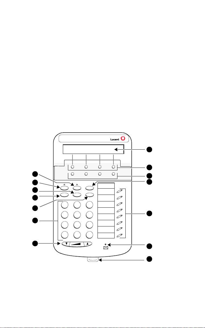
Use Figure 1 below to familiarize yourself with your 6400 Series telephone.
(The 6408D+ is shown in Figure 1.)
8
9
1
2
3
4
5
6
7
Menu Exit Prev Next
Spkr Mute Hold
Redial Trnsfr Conf
Test Ri ng
DEF
ABC
GHI
PQRS
*
1
4
7
3
2
MNOJKL
56
TUV
WXYZ
8
9
#
O
Tel #
10
11
12
13
FIGURE 1 The 6408D+ Telephone
14
1
Page 6
The following features correspond to the numbers in Figure 1.
1) Mute button 8) Display — available onl y on t he
6408D+, 6416D+ and 6416D+M, and
the 6424D+ and 6424D+M
2) Speaker button 9) Softkeys
3) Transfer/Test button 10) Display control button s
4) Redial button 11) Hold button
5) Conf/Ring button 12) Call appearance/feature buttons
6) Dial pad 13) Message light — label ed
7) Volume control button 14) Tray handle
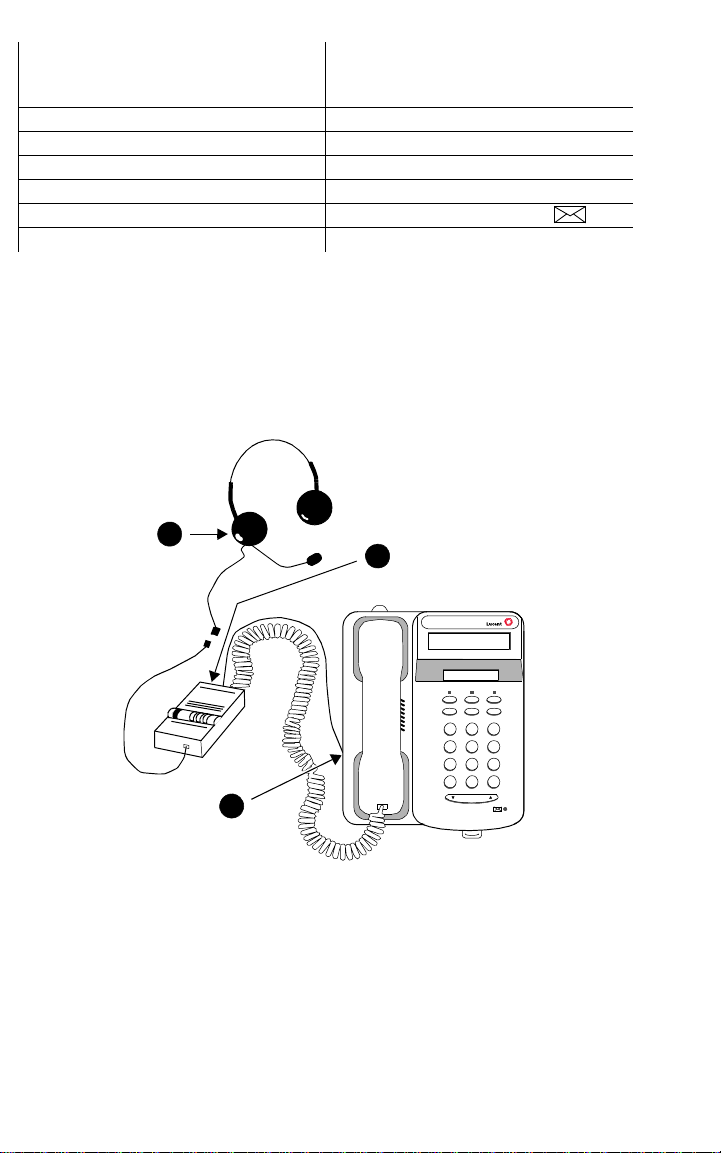
Headsets
On all of the 6400 Series telephones
except
the 6416D+M and 6424D+M, the
headset connection consists of a headpiece (shown as 1 in Figure 2 below)
and modular base unit (shown as 2 in Figure 2). In this instance , the ba se unit
plugs into the Handset jack (shown as 3 in Figure 2).
1
2
321
4*56
89
7
O#
3
Volume
FIGURE 2 The Headset Attached to the Handset Jack on a 6400 Series
Telephone (via a Modular Base Unit)
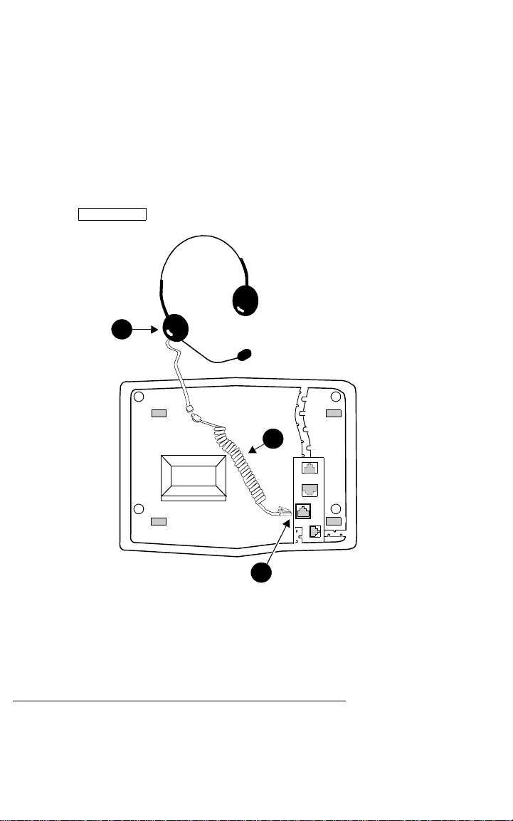
On the 6416D+M and 6424D+M sets, there is a jack provided for ONLY the
headset. In Figure 3, the headset is shown as 1; the Headset jack is sh own
either
as 2. On thes e sets, the head set can
be connected, wi th an ad apter cord
(shown as 3 in Figure 3), to the Headset jack on the back of the telephone
connected to a modular base unit which then plugs into the Headset jack.
2
or
Page 7
Note: When a modular base unit is used with the Headset jack, the handset
should remain plugged into the Handset jack.
The privacy of the W his pe r Page ann ou nce me nt c an not be guaranteed
when telephones have modular base units other than the M10L-8400
(Comcode: 407639715; PEC: 3122-022). The M10L-8400 is the only
modular base unit that should be used for the 6400 Series telephones.
Note that this does NOT apply to headsets plugged into the Headset
jack on the back of the 641 6D +M and 642 4D +M tel ephones that do not
require a modular base. For more information, see the instructions for
the Whisper Page feature in the Voice Features secti on.
Note: If you plug the headset directly into the Headset jack, you may use a
button on the adapter cord, if so equipped, to go off-hook and on-hook,
Headset On/Off
or a button may be administered.
1
3
2
FIGURE 3 The Headset Connected to the H eadse t Jack on the 6416D+M
and 6424D+M Telephones (No Modular Base Unit Required)
Headpieces
The following headpieces can be used with these telephones:
Headpieces with Modular Bases or with Adapter Cords
— Mirage® — Receiver fits over either ear. Not for noisy environments.
— StarSet
— Supra® Monaural — Adjustable headband and soft ear cushion.
®
— Eartip fits in ear canal.
3
Page 8
— Supra Monaural Noise-Canceling (NC) — Same as above with
noise-canceling microphone that reduces background noise transmission
by up to 75 percent.
— Supra Binaural — Sound in both ears.
— Supra Binaural Noise-Canceling (NC) — Same as above with
noise-canceling microphone on flexible boom; features windscreen and
reduces background noise transmission by up to 75 percent.
Note: For direct connection to the Headset jack on the 6416D+M and
6424D+M, use the following cord: HIC-01; Comcode: 408122950;
PEC: 3124-IC/A.
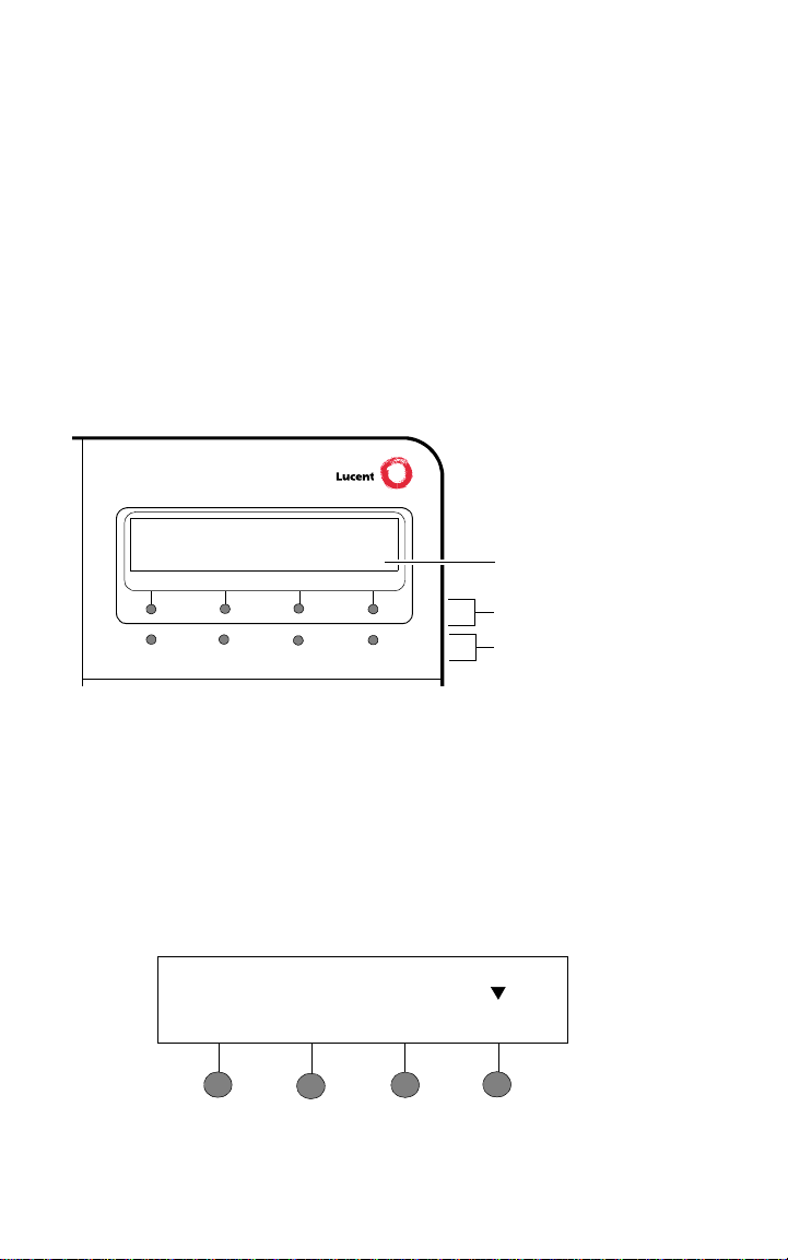
Using the Softkeys
The softkeys are the four unlabeled round keys located directly below the
display. The four round display control buttons, labeled Menu, Exit, Prev, and
Next are located under the softkeys. See Figure 4.
Display
Softkeys
NextPrevMenu Exit
FIGURE 4 The Display, Softkeys, and Display Control Buttons
Display
control buttons
Using the Softkey Feature Menus
There are three separate softkey feature menus. Each of these menus allows
you to select from four different features.
You can enter Softkey Mode (and view the softkey feature menu) by pressing
the display control button labeled Menu. The following is an example of a
softkey feature menu.
Dir Drop HFAns Timer
4
Page 9

The top line of each softkey feature menu screen shows you the status of
each of the four features. An arrow appears above the feature name or
abbreviation if that feature is active. In the above example, the arrow above
the Timer feature indicates that feature is active.
The second line on each softkey feature menu shows the features you can
access. To use any of these features, you must press the softkey below the
feature name or abbreviation.
Press the Next or Prev button until t he feature you wan t to use a ppears on the
display.
Note: An error tone (one beep) sounds when you have made an
inappropriate softkey entry.
Press the Exit button at any t ime t o exit th e softke y fea ture menu s and
return to normal call-handling operation.
Other Softkey Features That May Be On Your Display
There are 12 default features that can be accessed with the softkeys on a
6400 Series telephone. However, the system manager may substitute other
softkey features in their place.
Call-Handling Features
Conference
The Conference feature allows you to conference up to six parties (including
yourself) on a call.
To add another party to a call (for a total of six parties)
1. Press . [dial tone]
2. Dial the number of the new party and wait for an answer.
3. When you want to add the new person, press again.
4. Repeat Steps 1 through 3 for additional conference connections.
Conf
Conf
To add a call you have put on hold to another call you are connected to
1. Press . [dial tone]
2. Press the call appearance button of the call on hold (first call).
3. Press again.
To drop the last person added to the conference call
1. With a display: Press the Menu button and then press the softkey
below Drop.
Without a display: Press the button (if administered).
Conf
Conf
Drop
5
Page 10

Hold
The Hold feature puts a call on hold until you can return to it.
To put a call on hold while you answer another call or perform another
task
1. Press .
Hold
T o answ er a new call while acti ve on anothe r
1. Press .
Hold
2. Press the call appearance button of the incoming call.
To return to the held call
1. Press the call appearance button of the held call.
Note: If your telephone is connected to DEFINITY Release 7.1 or a later
release and if ther e is on ly one call on hol d at yo ur telep hone, y ou ca n
transfer the call or initiate a conference call by pressing or
Conf
without
first returning to the held call.
Trnsfr
Redial
The Redial (or Last Number Dialed) feature automatically redials the last
extension or outside number (up to 24 digits) you dialed.
To redial the last number that you dialed
1. Press .
.
Redial
Speaker (Listen-Only) and Group Listen
The Speaker feature allows you to place calls or access other features
without lifting the handset. However, in order to speak to the other party, you
must use the handset. With the Group Listen feature, the handset and
speaker are active at the same time.
Note: All of the 6400 Series telephones described in this manual can be
optioned for either a two-way
speaker
. Check with your system manager to see which feature you
speakerphone
or a one-way, listen-only
can use on your telephone.
T o use the listen-only speaker to place a c all without lifting the handset
or for any listening-only feature (such as monitoring a call on which
you have been put on hold or for group listening)
1. Press .
Spkr
2. Place a call or access the selected feature.
3. Adjust speaker volume if necessary:
To raise the volume, press the right half of the Speaker Volume control
button labeled ; to lower the volume, press the left half of the
Speaker Volume control button labeled .
6
Page 11

If you have a display, it shows the volume level: (There are eight
volume levels.)
->>>>>> +
To turn off the speaker and return to handset
1. Pick up the handset.
To end a call (while the handset is on-hook and only the speaker is
active)
1. Press .
Spkr
T o activ ate the s peaker w hile us ing the ha ndset so that both a re ac tive at
the same time (the Group Listen feature, if administered)
1. While you are using the handset, activate the speaker by pressing
Spkr
.
Note: If you hang up the handset within 10 seconds after pressing ,
Spkr
the call remains active on the speaker.
If you hang up the handset more than 10 seconds after pressing
Spkr
, the speaker will also turn off, and the call is disconnected.
Speakerphone
The two-way built-in speakerphone allows you to place and answer calls
without lifting your handset.
Note: Your telephone may be set for the two-way
one-way, listen-only
speaker
. Check with your sys tem ma nager to se e
speakerphone or
which of these features you can use.
Note: Speakerphones may not operate satisfactorily in every environment
(such as in very noisy locations). In such an environment, the
one-way, listen only speaker should be used.
Note: Some locations may wish to use the speakerphone for the Group
Listen feature. Wi th this fe ature you can hear the other person thro ugh
the handset and speakerphone, but in order to speak to the other
person, you must use the handset. Ask your system manager if the
Group Listen feature has been administered for your telephone.
To place or answer a call without lifting the handset, or to use the
speakerphone with any feature
1. Press .
Spkr
2. Place or answer the call, or access the selected feature.
3. Adjust speakerphone volume if necessary:
To raise the volume, press the right half of the Volume control button
labeled ; to lower the volume, press the left half of the Volume
control button labeled .
for the
7
Page 12

4. If you have a display, it shows:
(There are eight volume levels.)
->>>>>> +
To change from the speakerphone to the handset
1. Pick up the handset and talk.
To change from the handset to the speakerphone
1. Press .
Spkr
2. Within 10 seconds, hang up the handset.
To use the Group Listen feature (if administered) in which the handset
and the speaker are active at the same time
Spkr
1. While you are active on the handset, press
Note: If you hang up the handset within 10 seconds after pressing ,
.
Spkr
the call remains active on the speaker.
If you hang up the handset more than 10 seconds after pressing
Spkr
, the speaker will also turn off, and the call is disconnected.
To end a call
1. Press again.
Spkr
Test
The Test feature allows you to test the lights and display on your telephone.
To test the lights and display on your telephone
1. While on-hook, press and hold down .
Lights go on in columns, and if there is a display on the telephone, all
the display segments fill in.
2. To end test, release .
Trnsfr
Lights return to normal operation.
Note: If the lights or the display segments do not respond during the test,
see your system manager.
Trnsfr
Transfer
The Transfer feature allows you to transfer a call from your telephone to
another extension or outside number.
To send the present call to another extension
1. While on a call, press . [dial tone]
2. Dial the number to which the call is to be transferred. [ringing tone]
3. Remain on the line and announce the call.
(If the line is busy or if there is no answer, you can return to the held
Trnsfr
8
Page 13

call by pressing its call appearance button.)
4. Press again to complete the transfer.
5. Hang up.
Note: If your telephone is connected to a DEFINITY Release 6.3.2 or a later
release, your administrator may have chosen Transfer-on-Hang-up. In
this case, you can transfer a call by pressing , dialing the
number to which the call is to be transferred, and then hanging up.
To cancel an attempted transfer, press or press the original call
appearance. If your system has auto-hold activated, use to
cancel a transfer so that the potential transfer recipient is not left on
hold.
Trnsfr
Trnsfr
Drop
Drop
Getting Messages
Message
Your Message light goes on when a caller has left a message for you.
Note: If your telephone has a display, you may also be able to use the
Message Retrieval display feature.
For directions on retrieving your messages, see your system manager.
Selecting a Personalized Ring
Select Ring
The Select Ring feature allows you to choose your own personalized ringing
pattern for your telephone from among eight different patterns.
To select a personalized ringing pattern
1. While on-hook, press .
Conf
Current ringing pattern plays and repeats every three seconds.
2. Continue to press (and then relea se) to cycle throu gh all e igh t
ringing patterns.
3. If you want to save the ringing pattern currently being played, do not
press anymore. You will hear the selected ringing pattern two
more times, and then it will be automatically saved.
Conf
Conf
You will hear a confirmation tone (two rising tones), and your new
ringing pattern is set.
Note: If you go off-hook, receive a call, or lose power during selection, the
process is canceled and you must start again.
9
Page 14

Selected Voice Features
Spkr
Abbreviated Dialing/Automatic Dialing (AD)
The Abbreviated Dialing (AD) feature allows you to store selected telephone
numbers for quick and easy dialing. Each number can be a complete or
partial telephone number, an extension number, or a trunk or feature access
code. Abbreviated Dialing offers four possible types of lists — Personal,
Group, System, and Enhanced, and you can have a total of three lists. (Of
these three lists, you c an have onl y one Syste m List and o ne Enhanced Lis t.)
You program numbers on a Personal List; numbers on Group Lists are
programmable by the controller of the list; System Lists and Enhanced Lists
are programmable only by the system manager.
not
You can also prog ram a nu mb er o n an AD butt on th at i s
list. This Automatic Dialing number can be up to 16 digits and characters.
For all 6408+ telephones, and all 6408D+, 6416D+ and 6416D+M, and
6424D+ and 6424D+M telephones connected to DEFINITY switches 6.2
and prior releases, or when using the Program feature access code
To program/reprogram an AD button (administered as a feature button)
Note: The system manager must first program a call appearance/
feature button as an AD button before you can program a
number on it.
Note: There is a 10-second time limit between your entering the
Program mode and entering the first digit of an AD button, and
then a 10-second time limit between each digit. If you hear
intercept tone while you are programming the button, you have
exceeded the time limit and you must begin again.
1. Locate the Program button on your telephone. There are three
possibilities.
a. If you are using a telephone with a display, press the Menu button
and, if necessary, the Next or Prev button until Prog appears on the
display screen.
b. If you telepho ne does n ot have a displa y or if Prog is not a vailabl e on
your display, press administered as a feature button.
c. Ask your system manager for the AD Program feature access code.
2. Pick up the handset or press . [dial tone]
3. Press the Prog button (or dial the feature access code).
4. Press the AD button to be programmed.
5. Dial an outside number , extension, or featur e ac c ess c ode y ou w a nt t o
store (as you would normally dial it).
6. Press . [confirmation tone]
7. Repeat Steps 4 through 6 (within 10 seconds) to program additional
8. Hang up or press to end programming.
#
buttons.
Program
Spkr
stored on an AD
10
Page 15

For 6408D+, 6416D+ and 6416D+M, and 6424D+ and 6424D+M
telephones connected to a DEFINITY ECS Release 6.3 or later
To program an Abbreviated Dialing button on the softkey feature menu
screens or on a feature button
Note: If you make a mistake whi le progr ammin g an AD butt on o n your
display, you CANNOT move back a space to erase it. Instead,
save whatever you have entered by pressing the “#” key and
then start over.
1. Locate the Program button. It will either be a button labeled
Program
or you will see Prog on one of the feature menu screens.
2. To access the Program feature, press the Menu button, then the Next
or Prev button, if necessary, until you see Prog on the display. Then
press the softkey below Prog. If Prog is not on one of your feature
menu screens, press the button.
Program
Your telephone will automatically go off-hook, and the light next to
Spkr
will go on.
3. Select the feature button or the AD softkey you want to program. (To do
this, press the Menu button again, then press Next or Prev, if
necessary, until you see the AD softkey label, such as AD1, on the
display.)
You will see the message, Change number? Yes=1 No=2 on the
display.
4. If you want to enter a new number or c hange an e xisting num ber , press
the “1” key on the dial pad. If you do not want to change the number,
press the “2” key and skip to Step 6.
5. When you see the message Enter number: on the display, enter the
number you want that button to call. When you have finished entering
the number, press the “#” key. Go on to the next step.
Note: When you have changed the number called by a feature
button, you may want to change its label on the paper strip too.
6. When you see the message Change label? Yes=1 No=2, press the
“1” key on the dial pad to change a button label. If you do not want to
change the label, press the “2” key and skip to Step 8.
7. When you see the message Enter label on the display, use the dial
pad to enter the label you want, up to five characters. (Pressing a dial
pad key once enters the first letter on the key; if you want a different
letter or the number, press the key repeatedly until the character you
want appears on the display.) Press the “
space. When you have finished entering the label, press the “#” key.
8.
When you see the message Press button to program, decide if you
want to program an other butto n. If so, go back to Step 3. If not, go o n to
the next step.
Note: When you program a label, it does not appear on the display
until you hang up.
9. To exit from Programming mode, press the Speaker button.
” key to advance to the next
*
11
Page 16

To place an AD call
Spkr
Enhcd List
1. Press the selected AD button, either a feature button or the softkey
below the AD feature on the feature menu screens.
To program or reprogram an outside number, extension, o r feature
access code into an AD personal list
1. Locate the Program button on your telephone. There are three
possibilities.
a. If you are using a telephone with a display, press the Menu button
and, if necessary, the Next or Prev button until Prog appears on the
display screen.
b. If your telephone does not have a display or if Prog is not available
on your display, press administered as a feature button.
Program
c. Ask your system manager for the AD Program feature access code.
2. Pick up the handset or press . [dial tone]
Spkr
3. Press the Program button (or dial the feature access code).
4. Dial the Personal List number (1, 2, or 3).
5. Dial the list item (1, 2, 3...) .
6. Dial the number you want to store (up to 24 digits) as you would
normally dial it.
7. Press . [confirmation tone]
#
8. Repeat Steps 5 through 7 if you want to program additional items on
the same list; hang up and begin again at Step 2 if you want to program
items on another list.
9. Hang up or press to end programming.
Note: Record your personal list items on the Abbreviated Dialing list on the
cards in the tray under the telephone; group, system, and enhanced
list can be obtained from your system manager.
To place a call using an AD list button or code
1. Press the or or buttons (if administered)
or
Dial the appropriate AD List code for List 1, or List 2, or List 3.
Pers List Grp List Sys List
[dial tone]
Note: An (Enhanced List) may also be available; see your
system manager.
2. Dial the desired list item (1, 2, 3...).
Call Forwarding All Calls
The Call Forwarding feature temporarily forwards all your calls to another
extension or to an outside number, depending on your system.
To temporarily redirect all calls to an extension or outside number of
your choice
1. With a display: Press the Menu button and then press the softkey
below CFrwd (while on-hook or off-hook).
12
Page 17

Without a display: Press the button (if administered) (while
or
on-hook or off-hook)
Dial the Call Forward access code
Call Fwd
(while off-hook). [dial tone]
Note: If you have cons ole p ermis sion, next, d ial th e extens ion nu mber
whose calls are to be forwarded; receive dial tone.
2. Dial the extension or number where calls will be sent.
[confirmation tone]
3. Hang up.
To cancel Call Forwarding
1. With a display: Press the Menu button and then press the softkey
below CFrwd (while on-hook or off-hook).
2. Without a display: Press the button (while on-hook)
Call Fwd
or
Dial
the Call Forward cancel code (while off-hook). [confirmation tone].
Call Park
The Call Park feature allows you to put a call on hold at your telephone, for
retrieval at any extension.
To park a call at your extension (for retrieval at any extension)
Note: T o u se the Call Park fea ture on a telep hone with dis play (if Call Park is
one of your softkey features), press the Menu button and then the
softkey below CPark. Then hang up.
or,
the button (if administered) and hang up.
Call Park
if a button has been assigned to your telephone, press
Call Park
Otherwise, follow these instructions to park a call at your extension.
1. Press . [dial tone]
2. Dial the Call Park access code.
3. Press again.
Trnsfr
[confirmation tone]
Trnsfr
Call is parked at your extension.
4. Hang up.
To retrieve a parked call from another extension
1. Pick up the handset or press .
Spkr
2. Dial the Call Park access code. [confirmation tone]
3. Dial the extension where the call is parked. [confirmation tone]
If returning to a call parked at your telephone, dial your own
extension.
13
Page 18

Call Pickup and Directed Call Pickup
DirCall PkUp
The Call Pickup feature lets you answer a call at your telephone for another
extension in your pickup group. If you can use the Directed Call Pickup
feature, you can pick up a call ringing at a specific extension without the
person’s being a member of your pickup group.
To answer a call placed to a member of your pickup group when your
telephone is idle
1. With a display: Press the Menu button and then press the softkey
below CPkUp.
Without a display: Press the button (if administered)
Dial the Call Pickup access code.
CallPickup
Called telephone stops ringing, and you are connected to the ringing
call.
To pick up a call directly for someone else in your office
Note: Again, the Directed Call Pickup feature is designed for covering calls
for someone while they are away from their desk. In this case, you do
not
have to be a member of the same pickup group.
1. Press the button or Dial the Directed Call Pickup access
code.
2. Dial the extension of the ringing telephone.
Called telephone stops ringing, and you are connected to the ringing
call.
or
Leave Word Calling
The Leave Word Calling (LWC) feature leaves a message for a person at
another extension to call you back. The called party will be able to dial
message service (for example, an attendant, AUDIX or other voice mail
system, a covering user, etc.) to retrieve a short, standard message which
gives your name and extension, the date and time you called, and the
number of times you called.
To leave a message
answered, you hear a coverage or busy tone, or you have been put on
hold)
1. With a display: Press the Menu button and then press the softkey
below LWC before hanging up.
Without a display: Press the button (if administered) before
hanging up.
Message light goes on at the called telephone (if so equipped).
Note: If reorder tone is heard, message is not stored; try again.
To leave a message without ringing an extension
1. With a display: Press the Menu button and then press the softkey
after dialing an extension (when your call is not
LWC
[confirmation tone]
14
Page 19

below LWC.
Without a display: Press the button or Dial the Leave Word
Calling access code (while off-hook).
2. Dial the extension.
[confirmation tone]
LWC
[dial tone]
Message light goes on at the called telephone (if so equipped).
3. Hang up.
To cancel a Leave Word Calling message
Note: You cannot cancel a message left for an AUDIX subscriber.
1. With a display: Press the Menu button and then press the softkey
below CnLWC (while on-hook or off-hook).
Without a display: Press the button (wh ile on-hook or
off-hook)
2. Dial the extension. [confirmation tone]
Note: If reorder tone is heard, the message is not canceled; try again.
or
Dial the Leave Word Calling cancel code (while off-hook).
Cancel LWC
[dial tone]
Self-Administration
If your telephone has a display and the Self-Administration feature has been
activated, you will be able to add (or to remove) feature buttons on your own
telephone using the softkeys and the display control buttons.
To administer any of the availa ble featur es
1. Press the Menu button and then the softkey below Admin.
Note: The telephone must be idle; that is, there must NOT be any
active or held calls.
2. If necessary, enter your security code at the telephone dial pad.
Note: If you enter an invalid security code,
the display shows Incorrect Security Code and Cont. (for
Continue).
When you have entered the security code, press the softkey below
Done.
Press the softkey below Cont. to proceed.
The display shows the first SELECT FEATURE screen which lists the
first set of four self-administrable features. To see the second set of four
features, press the Next button. To go back one menu screen, press the
Prev button.
3. Press the softkey below the feature you want to place on an available
feature button such as CPkUp (Call Pickup) or SAC (Send All Calls).
Note: If you choose the Automatic Dialing or Group Paging feature,
the display prompts you to add a number such as a telephone
number, extension, or trunk code that will be associated with
this particular button. When you have entered the correct
number, press the softkey below Done.
Note: If you wish to see the full name of any of the features on the
feature menu screens (called LongMode), press the softkey
the telephone beeps and
15
Page 20

below Expl?.
4. Press the button on which you wish to assign this feature.
If the feature is successfully administered on the feature button, the
display shows: “Button Programmed!” Go on to Step 5.
Note: If there is already a feature programmed on that button, you see the
following screen:
XXXXX FEATURE ON BUTTON
Replace Keep Delete
On this display screen, press either of the softkeys below Replace if
you want to replace the current feature on that button. Press the
softkey below Keep if you want to keep the feature on that button.
Press the softkey below Delete if you want to delete the feature from
the button and leave that button blank.
5. When you see the “BUTTON PROGRAMMED!” screen on the display,
do one of the following:
— If you want to a dminister another button on your telepho ne , p r es s the
softkey below Cont (Continue) on the second line of the “BUTTON
PROGRAMMED” screen. The display returns to the feature list.
Repeat Steps 3 and 4 to administer other buttons.
— To end self-administration and return to Normal call-handling mode,
press the Exit button.
Note: Be sure to write the name of the self-administered feature(s) on the
telephone designation card next to the appropriate button.
Send All Calls
The Send All Calls feature temporarily sends all your calls to another
extension i n the same system.
Note: Before you can u se this feat ure, your sy stem manag er must provide a
coverage path for your extension.
To send all calls (except priority calls) immediately to coverage
1. With a display: Press the Menu button and then press the softkey
below SAC (while on-hook).
Without a display: Press th e button (while on -hook)
Send Calls
the Send All Calls access code (while off-hook) [confirmation tone]
To cancel Send All Calls
1. With a display: Press the Menu button and then press the softkey
below SAC again (while on-hook).
Without a display: Press the button again (while on-hook)
or
Dial the Send All Calls cancel code (while off-hook).
Send Calls
[confirmation tone]
16
or
Dial
Page 21

Whisper Page
Whisper Page
The Whisper Page feature allows you, if you have appropriate permissions,
to make an announcement to a person at another extension currently on
another call. Only the person at the other extens ion hears the
announcement; the other person on the call cannot hear the message.
Note: If you are connecting the headpiece to the Handset jack on the
6400 Series telephones, the M10L-8400 is the only modular base uni t
that should be used. If you use any other modular base unit, the
Whisper Page announcement may be overheard by the other person
on the call.
To make an important announcement (such as an incoming call) to
someone at another extension busy on another call
or
1. Press the button
Both people on the other call hear a beep.
The person whom you have called can press the button
which forms a two-party speaking path with your telephone. The other
call is put on hold and that person cannot hear your conversation.
2. Speak with the person you have called.
Note: If the perso n whom y ou have called is not using th e teleph one at
the time you activate Whisper Page, the call is converted to a
normal call.
Note: Any person in the system with the button
administered on th e telephone can bloc k Whisper Pa ge calls b y
pressing the button.
Whisper Off
Dial the Whisper Page access code.
Whisper Answer
Whisper Answer
Display Features
Note: To ensure easier display vis ib ili ty, the display on the 6408 D +, 6 416 D +
and 6416D+M, and 64 24D + a nd 642 4D +M ca n be le ft in its ho riz onta l
position or can be raised to a slightly steeper angle. Check which
viewing angle is best for your workstation.
Time and Date
Ordinarily, the time and the date will appear on the upper line of your display.
not
(The 6408+ does
so if there is an error, contact your system manager.
Note: On initially plugging in a 6400 Series display telephone or after a
power outage, it may take approximately 15 minutes before the time
and date appear on the screen.
Call Information
The 6408 telephones have eight call appearance buttons; the 6416D+ and
6416D+M have 16; the 6424D+ and 6424D+M have 24 buttons. Beginning
with the first button in the upper left hand corner of your faceplate and going
down, the display identifies the buttons in the left column as a thro ugh h. The
have a display.) The time and date are set at the switch,
17
Page 22

buttons in the right column begin with i and then go throug h p (on the 6416D+
and 6416D+M) and through x (on the 6424D+ and 6424D+M). When the
display shows , it represents call information for the first call
appearance button. Th e next bu tton dow n would be show n as , and
a=
b=
so on.
When you dial an extension, that number is shown and then replaced by the
called party’s name and extension. When a call is received from another
extension, the caller’s name is shown; when a call is received from outside,
“OUTSIDE CALL” or a trunk identifier is shown.
The display remains in Normal (call-handling) Mode until you activate one of
the other display or softkey features. After using any of these features, return
to Normal Mode by pressing the Exit button.
Call Timer and Timer
The Call Timer and the Timer features are used to measure elapsed
time on a call.
However, the Call Timer feature can be used ONLY if your telephone
is connected to a DEFINITY ECS Release 6.3 or later. This feature,
once activated, measures elapsed time
you turn off the Call Timer feature.
The Timer feature must be turned on
to time. At the end of the call, you must im mediately turn off the feature.
This feature can be used with
any
Check with your system manager to see if you can use either of these
features.
To use the Call Timer feature to measure elapsed time on telephone
calls
1. Press the Menu button and then press the softkey below CTime
or,
if CTime is not available on your display, press the
button (if administered).
The Call Timer will measure elapsed time automatically on all calls
until you turn off the Call Timer feature.
2. When you want to turn off the Call Timer feature, press the Menu
button and press the softkey below CTime
or,
if you have activated this feature with
Call Timer
To use the Timer feature to measure elapsed time on an individual
telephone call
1. Press the Menu button and the n pre ss t he s oftk ey b el ow Timer (which
exits you from softkey mode)
or,
if Timer is not available on your display, press the button
(if administered).
2. To sto p the tim er and cl ear the di splay, press the Menu button and then
press the softkey below Timer again
or,
if Timer is not available on your display, press again.
button.
automatically
on all calls until
for each individual call
DEFINITY switch release.
Call Timer
Call Timer
,
press the
Timer
Timer
you wish
18
Page 23

Directory
The Directory feature allows you to search for the extension of another user
in your location by keying in the user’s name at the dial pad.
To search the director y for a name
1. Press the Menu button and then press the softkey below Dir
or,
if Dir is not available on your display, press the button
Directory
(if administered).
2. Key in the selected name with dial pad keys:
last name, comma (use ), first name or initial.
*
3. Press the Next button for each successive directory name you wish to
see.
4. To search for a new name, press the softkey below Dir or press the
Directory
button and go through the above sequence again.
5. When you are ready to exit the directory, press the Exit button.
To place a call to the name shown on the display
1. Pick up the handset.
2. While the name is shown, press the button (if administered)
or,
if you do not have a button on your set, press the Exit
Call Disp
Call Disp
button and then dial the number using the dial pad.
Note: You can also leave your handset on-hook. The speakerphone
will turn on automatically when you press .
Call Disp
Exit
Use the Exit feature to leave Disp lay Mode (afte r using any displ ay or softkey
feature) and return to Normal Mode. You can then use the disp lay to view the
time and date and to identify call appearance, calling/called party, and
calling/called number.
To exit a display feature and return to Normal (display) Mode
1. Press the Exit button.
Display will show the time and date or, when applicable, call/caller
information.
Inspect
The Inspect feature shows you call-related information for an incoming call
when you are already active on a call, or, with this feature, you can see who
is on hold.
To use the Inspect feature
1. Press the Menu button and then press the softkey below Inspt
or,
if Inspt is not available on your dis pl ay, press the button (if
administered).
19
Inspect
Page 24

2. Press the call appearance button in question.
Pers List
Enhcd List
Information is shown on the display screen;
you remain connected to the present call.
3. To return to the held call, press the Exit button and then the call
appearance button of the held call.
.
Stored Number/View
The Stored Number or View feature all ows you to ch eck: 1) the number st ored
as an item on an Abbreviated Dialing list, 2) the number you last dialed (via
Last Number Dialed feature), or 3) the name of the feature that has been
programmed on any of your telephone’s call appearance/feature buttons.
To view the number stored as a list item
1. Press the Menu button and then press the softkey below BtnVu
or
Press the button.
2. Press the selected or or button
or
Dial the appropriate AD List code for List 1, or List 2, or List 3.
Note: An (Enhanced List) may also be available; see your
3. Dial the selected list item (1, 2, 3...).
Stored number is shown.
4. Hang up.
5. To return to the Normal (display) Mode, press the Exit button or begin
again at Step 2 to see another stored number.
To view the feature stored on a call appearance/feature button OR the
last number you dialed OR a number stored on an AD button
1. Press the Menu button and then press the softkey below View
or,
if View is not available on your display, press the button.
2. Press the selected feature button.
Note: To view the last number you dialed, press , or to view
3. To return to the Normal (call-handling) Mode display, press the Exit
button or repeat Step 2 to see another stored number.
View
Grp List Sys List
system manager.
View
Redial
the number stored on an AD button, press the selected AD
button.
Modular Interface Capabilities
If you are using a 6416D+M or 6424D+M telephone, you can install a module
in the telephone ’s des ktop stan d for inc reased s et functiona lity. Figure 5 shows
the rear of the desktop stand on these telephones. Number 1 in Figure 5
shows the module opening on the back of the stand. Remove the cover
(shown as 2) before you install the module. For more information about
specific modules, see the documentation supplied with the module.
Note: These modules can ONLY be used in the desktop position; they
20
Page 25

CANNOT be used if the telephone is to be wall-mounted.
1
2
FIGURE 5 A Rear View of the 6416D+M and 6424D+M Telephones
Telephone Installation
All of the 6400 Series telephones described in this manual can be either
desk-mounted or wall-mounted. Use the following directions for installing any
of these telephones. Figure 6 shows the back of the 6400 Series telephones.
1
2
2
1
LINE
EX MOD
7 6
FIGURE 6 The Bottom of the 6400 Series Telephones
3
4
7
6
Desktop Installation
Note: In non-modular 6400 Series telephones, you can use the telephone
without the desktop stand, if you so choose.
stand contains the modular interface, the desktop stand must be left
connected to the telephone.)
If you do not use the telephone with attached desktop stand, it is
suggested that you place small round feet (included i n a p las ti c b ag in
the box in which the telephone was packed) on each corner of the
21
(If the telephone desktop
4
3
5
Page 26

bottom of the telephone housing.
1. Turn the telephone face down on a flat surface.
2. Remove the desktop stand (the upper tabs on the stand are shown as
2 in Figure 6; the lower tabs are shown as 7 in Figure 6). If you are
using a 6416D+M or 6424D+M telephone and want to install the
adjunct module, do so now be fore proceeding with the foll ow in g s tep s.
For more information on the installation of the module, see the
documentation that came in the box with the module.
3. Snap one end of the line cord (D2R or D8W) into the “LINE” jack (3 in
Figure 6) on the bottom of the telephone.
4. If you are installing a 6416D+ or 6416D+M or a 6424D+ or 6424D+M
with a connected expansion module, snap one end of the expansion
module cord into the “XM24” jack (4 in Figure 6).
5. Thread the line cord (and expansion module cord, if appropriate)
through the routing channel leading to the top of the desktop stand
(1 in Figure 6). Make sure that each cord is placed securely under the
square tabs in the routing channel.
6. Snap one end of the coiled handset cord into the Handset jack (6 in
Figure 6). This jack is label ed . Thread the handset cord into the
channel leading to the side edge of the telephone).
7. Turn the telephone right side up, with the front facing you.
8. Snap the free end of the handset cord into the handset and place the
handset in the cradle.
9. If appropriate, snap the free end of th e e xp ans io n m od ul e c ord in to the
TEL SET jack on the expansion module.
10. Snap the free end of the line cord into the modular wall jack.
1 1. Lift the handset and listen for dial tone . If there is no dial ton e, check all
wire connections to make sure they are secure.
Note: If you are using a headset with the telephone, you can connect it to the
Handset jack (6 in Figure 6) or the Headset jack on some telephones
(5 in Figure 6).
Wall Installation
Note: For wall-mounting, you will need a 1-foot line cord. (This cord is
supplied with the telephone, but can be ordered by using this
comcode: 103786760.)
If you are wall-mounting the telephone, you should remove the
tray from the base of the telephone. For this purpose, use the
instructions listed under “Removing the Telephone Tray” later in this
guide.
1. Make sure the 8-conductor wall mount plate is in place.
2. Do the following to reverse the handset hook. (a i n Fig ure 7 shows the
handset retainer located under the handset.)
— In order to release the handse t retainer hook, press down on the hook
22
not
Page 27

and slide it toward the top of the telephone. (See b in Figure 7.)
— Rotate the hook 180 degrees (as in c in Figure 7) and then slide it
back into its slot so the bottom part now sticks out from the top. (See
d in Figure 7.) Snap the hook firmly into place.
a.
c.
b.
d.
¾
FIGURE 7 Removing, Rotating, and Replacing the Handset Retainer
3. Place the telephone face down on a flat surface.
4. Remove the desktop stand which is attached to the base of the
telephone by tabs on the top and back of the stand, shown as 2 and 7
in Figure 6 on page 21.
Note: Figure 8 below shows the removal of the desktop stand from
two different 6400 Series telephone models. Check to see
which model is most like the back of your telephone.
— Press inward on the top of the stand until y ou can li ft t he upper tab(s)
of the stand (shown as 1 in the figure below) out of the tab slot(s)
(shown as 2 in the figure below) on the telephone.
— Lift the bottom of the stand out of the lower tab slot(s).
1
2
FIGURE 8 Removing the Desktop Stand
2
23
1
2
2
Page 28

5. Reverse the desktop stand so that the larger end is facing down.
6. Snap the line cord into the “LINE” jack in the bottom of the telephone
and coil the excess cord in the back of the deskstand.
7. Snap one end of the coiled handset cord into the Ha ndset jack (la beled
). Thread the handset cord into the channel leading to the side
edge of the telephone
8. Slowly lower the reversed deskstand onto the bottom of the telephone
until the tabs at the top and bottom of the deskstand snap into the
appropriate slots on the bottom of the telephone.
9. Place the free end of the line co rd th rou gh the ope ning in the middle o f
the deskstand and then snap the free end of the line cord into the wall
jack.
10. Place the base of the telephone on the wall-jack mounting studs, and
pull downward until it is secure. (See Figure 9.)
FIGURE 9 Placing the Telephone on the Wall Jack Mounting Studs
11. Snap the free end of the handset cord into the handset and place the
handset in the cradle.
Note: The handset hook you repositioned will hold the handset in place.
12. Lift the handset and listen for dial tone. If there is no di al tone, check all
wire connections to make sure they are secure.
24
Page 29

Removing the Te lephone Tray
You may wish to remove the tray from the base of the telephone, especially if
you are wall-mounting the telephone. See Figure 10 for further help.
1. Pull the tray from the base of the telephone as far as it will go.
2. Using your thumb, press down on the center of the tray.
3. Continue to pull the tray until it is completely separated from the base.
1
2
3
FIGURE 10 Removing the Tray from the Base of the Telephone
25
Page 30

Installing the Designation Card
Use the button designation card to write the telephone number, extension,
name, or feature th at each cal l appearan ce/feature button c an acces s. In orde r
to help you match the designation cards with the call appearance/feature
buttons on the telephone, the columns of button labels are marked with the
6400 Series multi-line telephone model with which the label can be used.
Below the perforated bottom edge of each designation card is a telephone
number card on which you can write your telephone number or extension.
To label and install the designation card and telephone number card
1. Print the numbers/features on the button designation card that
corresponds with the telephone you are using, and type or write your
phone number or extension on the telephone number card (labeled
Tel no.).
2. Crease the perforated edges of the cards you have filled out and then
tear the button designation strips and the station number card along
the perforations.
3. Place the button designation card and telephone number card under
the plastic card cover on the telephone by doing the following:
— The transparent designation card cover is attached to the frame of
the telephone by tabs on the top and bottom of the cover. Remove
the cover by pulling the top tab forward and then lifting the bottom of
the transparent cover from the telephone.
— Place the designation card(s) on the telephone and then replace the
transparent cover over the card by inserting the tabs at the bottom
and then pressing the top down until it clicks.
Note: You can order additional designation cards in quantities of 25 cards
and 100 cards per package. Use the following comcodes when you
place your order.
25 sheets of designation and telephone number cards:
Comcode: CC847984614
100 sheets of designation and telephone number cards:
Comcode: CC847984622
26
Page 31

Tones and Their Meaning
Note: The tables below describe the defaults for each ringing and feedback
tone. Check with your system manager to verify if the descriptions in
the Meaning column are accurate for your system.
Ringing T o nes are produced by an incoming call.
Ringing Tones
Rings Meaning
1 ring A call from another extension.
2 rings A call from outside or from the attendant
3 rings A priority call from ano ther extensio n, or
from an Automatic Callback call you
placed.
◆
Feedback tones are those which you hear through the handset (receiver) or
the speaker.
Feedback Tones
ring-ping
(half-ring)
A call redirected from your telephone to
another because Send All Calls or Call
Forwarding All Calls is active.
Tones Meaning
busy A low-pitched tone repeated 60 times a
minute; indicates the number dialed is in
use.
call waiting
ringback
confirmation Three short bursts of tone; indicates a
A ringback tone with lower-pitched signal at
the end; indicates the extension call is
busy , and th e calle d party has bee n given a
call waiting tone. If you hear this tone, you
may wish to activate Automatic Callback
feature activation or cancellation has been
accepted.
27
continued on next page
Page 32

Feedback Tones
Tones Meaning
(continued)
coverage One short burst of tone; indicates your
call will be sent to another extension
to be answered by a covering user.
dial A continuous tone; indicates dialing
can begin.
intercept/
time-out
recall dial Three short bu rsts of tone fo llowed by
reorder A fast busy tone repeat ed 120 tim es a
ringback A low-pitched tone repeated 15 times
An alternating high and low tone;
indicates a dialing error, a denial of
the service requested, or a failure to
dial within a preset interval (usually
10 seconds) after listing the handset
or dialing the previous digit.
a steady dial tone; indicates the
feature request has been accepted
and dialing can begin.
minute; i ndicates all trunks are busy.
a minute; indicates th e n um ber dialed
is being rung.
Line and Feature Button Lights
Line and Feature Button Lights
Light Meaning
Steady red The line you are using or will use when you lift
the handset or press the Speaker button.
Steady green The line is in use, or the feature programmed
on this button is on.
Blinking green You have put a call on hold on this
line button.
28
 Loading...