

Page 1
Avaya
Voice Portal
An IP/CCMS connector, the
link between the PBX and
Voice Portal handles both call
data information and voice
communication
Configuration Note 3910 – Rev. F (1/08)
Avaya Voice Portal (Software application)
Telephone
Telephone
Central
& PSTN
Central
Office
Digital
Trunks
Office
G3/G600/S8700/S8300
Important: This Configuration Note specifies the minimum configuration
required by voice portal. It is advisable to consult with your
application designer to ensure you have a configuration to
meet your specific requirements.
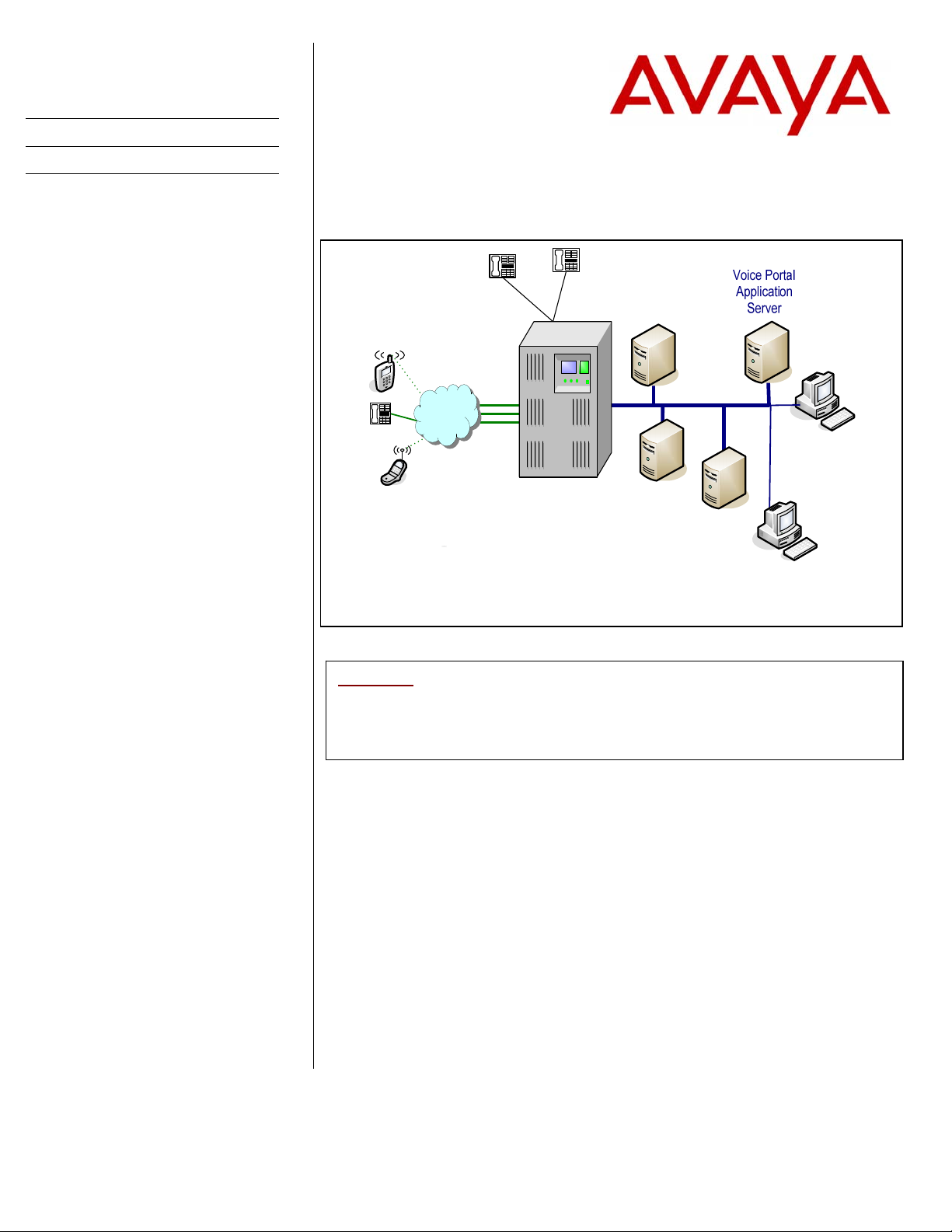
1.0 METHOD OF INTEGRATION
There is one IP Link (Ethernet) from the Voice Portal’s Media Processing Platform
(MPP) server to the PBX. The integration is done via the IP SoftPhone protocol with
voice transmission and integration information carried over IP.
2.0 VOICE PORTAL ORDERING INFORMATION
For details on server hardware and software requirements please refer to:
Telephone
AVAYA
Minimum Software
Release CM 2.1
Text-to-Speech
Server
Local Area Network
Media
Processing
Platform
(Server)
Voice Portal
Management
System
`
Application
Development
for Speech
Appls.
`
Web Browser
for Configuring
Voice Portal
• Avaya Voice Portal 3 – Concepts and Planning
• Avaya Voice Portal 3 – Installation and Configuration Guide
Disclaimer: Configuration Notes are designed to be a general guide reflecting AVAYA experience configuring its systems. These notes cannot
anticipate every configuration possibility given the inherent variations in all hardware and software products. Please understand that you may
experience a problem not detailed in a Configuration Note. If so, please notify the Technical Assistance Center at 408.922.1822, and if
appropriate we will include it in our next revision. AVAYA accepts no responsibility for errors or omissions contained herein.
Page 2

PBX hardware requirements
PBX Software Requirements
F E A T U R E S
Voice Portal
3.0 PBX HARDWARE REQUIREMENTS
3.2 PBX SOFTWARE REQUIREMENTS
Important: Account teams should check with Avaya Services to determine if any other patches
4.0 SUPPORTED FEATURES
The Voice Portal system provides either full or partial automation of telephone
transactions that would otherwise be performed by an operator, attendant, or
contact center agent. These automated transactions are driven by speech
applications where each speech application is designed and developed to satisfy
specific customer needs.
Note
For G3 and traditional Cabinet S87x0/S8500 PBXs
• TN2302 AP Media Processor / TN2602 AP Media Resource circuit
packs (Crossfire).
levels for the IP telephone to audio levels for DCP phones when IP phones are
used in a call with non-IP telephones.
AP Media circuit packs are used to convert the audio
*FOR FAX Support: TN2302 Firmware 111 minimum /
TN2602AP Firmware 24 minimum
• TN799 Control-LAN (CLAN) circuit pack for the signaling capability
(either the B or C vintage) on the csi, si, and r platforms.
For S8300/S87x0/8500 using newer media modules
• Use of EXT 2 port on the front panel of G700 to connect to MPP
Server.
For connecting to PBX:
• Category 5 wiring or line cord to connect MPP Server to PBX.
• Minimum software release CM2.1
• Minimum release Avaya CM 3.1 and Special Application (Green Feature)
SA8874 - Call status messages for 7434ND IP phones is strongly
recommended. SA8874 provides detailed call-progress indications to Avaya
VP when the incoming or outgoing call is either a station-to-station call or is
over a PRI trunk. This allows supervised transfer to fully integrate with Voice
Portal for call progress and handling. Without this feature supervised transfers
will function similar to blind transfers and callers may hear busy or similar
tones that would otherwise be avoided. To order SA8874 use Material Code
#202775. Note
• AAS capability – Avaya CM station type (7434ND) used by Avaya VP does
not allow for Auto-Available Skill (AAS) capability to be configured. To
resolve this issue install patch 11586, available through CM 3.0 Load 346.
may be needed for the Avaya CM release they will integrate with Avaya VP.
: With Voice Portal 4.0 or higher, an alternate gatekeeper discovery address can
be configured on the VPMS to be used if the primary address does not respond.
: There is a cost to add this feature to your PBX.
2
The above information is provided by AVAYA Inc. as a guideline. See disclaimer on page 1
Page 3
Configuring the PBX
to integrate
Voice Portal
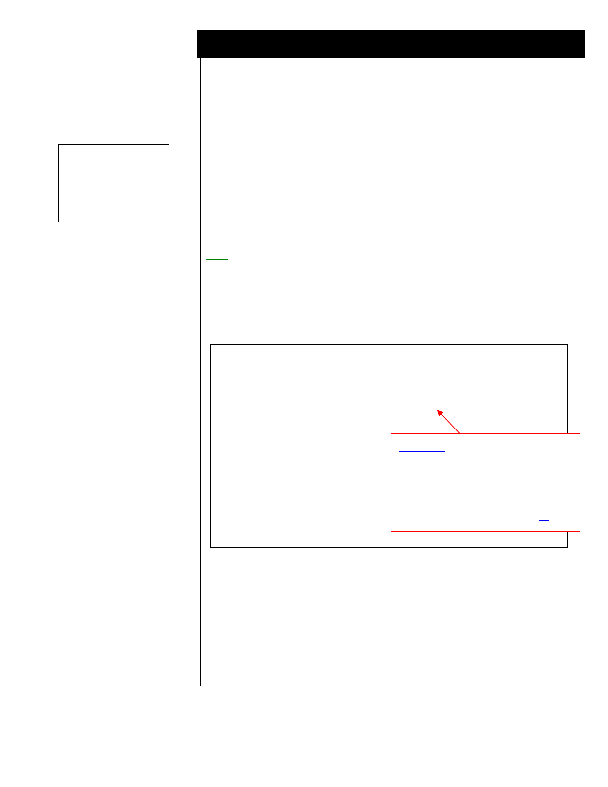
5.0 CONFIGURING THE PBX TO INTEGRATE
The following tasks must be completed when programming the PBX to integrate.
IMPORTANT NOTE: Although the integration uses the IP Softphone protocol for
connectivity, they are defined within the PBX as 4-wire 7434ND (numeric
display) sets.
The tasks are as follows:
• Configure Switch System Settings
• Create Pilot number for the Voice Portal hunt group.
• Define the stations assigned to Voice Portal.
NOTE
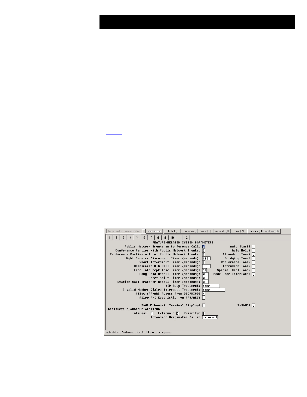
5.1 SYSTEM PARAMETER FEATURES
Under Parameters double-click change system-parameters features.
Select tab 5 and verify that the field 7434ND? is set to “y”
Figure 1: System Parameters Features - Tab 5
: A number of configuration shows screens that follow are shown
displayed in the Avaya Site Administration GUI, also known as GEDI
(Graphically Enhanced DEFINITY interface). Screens and parameters
may appear different depending on PBX software revision and load.
Please note, for those using Definity System Administration the tabs on
the following screens correlate to the page #s as displayed on the admin
screens.
3
The above information is provided by AVAYA Inc. as a guideline. See disclaimer on page 1
Page 4
Ensuring the best
audio quality.
“disp ip-codec-set 1”
Voice Portal
To ensure best audio quality when calling Voice Portal from an IP phone, use the
“display ip-codec-set 1” command and verify that a G711MU codec is shown at
the first position.
Voice Portal supports Voip Audio Formats set to audio/basic(default) or audio/x-
alaw-basic. This selection is defined on the VPMS’s web page under the VoIP
Settings. Make sure the switch is configured to support the codec you select.
If you have selected audio/basic on the VPMS, then the codec set on the switch
should include G711MU. If you have selected audio/x-alaw-basic on the VPMS,
then the codec set on the switch should include G711A.
Note
Figure 1a: Codec Sets
display ip-codec-set 1 Page 1 of 2
Codec Set: 1
Audio Silence Frames Packet
Codec Suppression Per Pkt Size (ms)
1: G.711MU n 3 30
2: G.711A n 3 30
3:
4:
5:
6:
7:
Media Encryption: none
5.1.1 Ensuring best-quality IP Audio
: When Voice Portal negotiates a codec from the switch at call setup, it
typically will use the first codec on the list (below). A G711MU codec
is typically used in the US and Japan, while a G711A is used in Europe
and other parts of the world.
IP Codec Set
(Continued on next page)
Important: This setting should be set to
match the same setting on
the Voice Portal system.
To work properly with Avaya Voice
5.1.2 IP-IP Direct
Audio settings
Portal, the required minimum Packet
Size setting in the IP-Code-Set is 20
-continued on next page -
4
ms.
The above information is provided by AVAYA Inc. as a guideline. See disclaimer on page 1
Page 5

FAX: Starting with Voice Portal 4.1
a fax tone detection feature is
available. For this feature to
work, you must configure the PBX
correctly.
: Turn off the special fax handling
Note
as shown here in this codec set. This
allows the fax to be handled as an
ordinary voice call.
With a codec set that uses G.711, this
setting is required to send faxes to
non-Avaya systems that do not support
T.38 fax.
Voice Portal
display ip-codec-set 1
Page 2 of 2
IP Codec Set
Allow Direct-IP Multimedia? n
Mode Redundancy
FAX off 0
Modem off 0
TDD/TTY US 3
Clear-channel n 0
Voice Portal supports Media Encryption set to Yes (default) or No. This selection is
defined on the VPMS’s web page under the H.323 Connections. Be sure the switch
has Media Encryption appropriately configured for AES (Encryption), AEA
(Encryption) and/or None (No Encryption).
If Voice Portal has Media Encryption set to Yes, then the MPP will support Media
Encryption for the switch set to AES(Encryption), AEA (Encryption) and/or None
(No Encryption).
If Voice Portal has Media Encryption set to No, then the switch must have None
(No Encryption) enabled (see above - Figure 1a Codec Sets). If this option is not
set, then calls to the MPP will get dead air.
The IP-IP Direct Audio settings must be enabled. Figure 1b (below) shows how to
verify this. Use the “display ip-network-region 1” command and review.
5.1.2 Media Encryption
5.1.3 IP-IP Direct Audio settings
-continued on next page -
5
The above information is provided by AVAYA Inc. as a guideline. See disclaimer on page 1
Page 6

Verify Direct Audio
settings are set to “yes”
“disp ip-network-region 1”
Voice Portal
Figure 1b: IP-Network-Region 1 (Tab 1 or Page 1)
5.2 Configuration Requirements for Voice Portal Stations
• Create a sequential range of stations that will be used by Voice Portal.
Figure 2: Station options – Page 1 of 5
Note
Each station should have the following five fields set as shown below.
1. Type = 7434ND
2. Display Name = Speech Access
“*Columbia 8050” in our example below)
3. Display Module = y
(this name would replace
Note: only after you select “y” will you
see Display Language appear
4. Display Language = English
5. Security Code = Set to a valid value.
Note
: Voice Portals allows the security
codes to be the same for every station,
or incrementally set for stations in a
given range.
6. IP SoftPhone? = y
: The following screens for configuring the Station Options are shown
using the standard terminal display. If you are using the Avaya Site
Administration GUI, also known as GEDI (Graphically Enhanced
DEFINITY interface), the page numbers would be depicted graphically as
6
The above information is provided by AVAYA Inc. as a guideline. See disclaimer on page 1
Page 7

Note: When the IP SoftPhone
g
option is set to “y” as
shown in Figure 2 then
the multimedia mode as
shown in Figure 3
(Station Options - page
2 of 5) will default to
“enhanced” and cannot
be chan
ed.
Voice Portal
7
Important
enter IP (see red note below left). Once you have added the user, the system then
assigns a port.
display station 57001 Page 1 of 5
STATION
Extension: 57001 Lock Messages? n BCC: 0
Type: 7434ND Security Code: * TN: 1
Port: S00400 Coverage Path 1: COR: 1
Name: Elena1 Coverage Path 2: COS: 1
Hunt-to Station:
STATION OPTIONS
Loss Group: 2 Personalized Ringing Pattern: 1
Data Module? n Message Lamp Ext: 57001
Display Module? y
Display Language: english Coverage Module? n
Media Complex Ext:
IP SoftPhone? y
Remote Office Phone? n
tabs. Screens and parameters may appear different depending on PBX
software revision and load.
: When configuring station options, the Port field is where you would
Figure 3: Station options – Page 2 of 5
The default feature options should be left unchanged.
display station 57001 Page 2 of 5
STATION
FEATURE OPTIONS
LWC Reception: spe Auto Select Any Idle Appearance? n
LWC Activation? y Coverage Msg Retrieval? y
LWC Log External Calls? n Auto Answer:
none
CDR Privacy? n Data Restriction? n
Redirect Notification? y Idle Appearance Preference? n
Per Button Ring Control? n
Bridged Call Alerting? n Restrict Last Appearance? y
Active Station Ringing: single
H.320 Conversion? n Per Station CPN - Send Calling Number?
Service Link Mode: as-needed
Multimedia Mode: enhanced Audible Message Waiting? n
MWI Served User Type: Display Client Redirection? n
AUDIX Name: Select Last Used Appearance? n
Coverage After Forwarding? s
Multimedia Early Answer? n
Remote Softphone Emergency Calls: as-on-local Direct IP-IP Audio Connections? y
Emergency Location Ext: 57001 IP Audio Hairpinning? y
The above information is provided by AVAYA Inc. as a guideline. See disclaimer on page 1
Page 8

Voice Portal
8
Figure 4: Station options – Page 3 of 5
Set the Button Assignments for the first two call appearances as shown.
display station 57001 Page 3 of 5
STATION
SITE DATA
Room: Headset? n
Jack: Speaker? n
Cable: Mounting: d
Floor: Cord Length: 0
Building: Set Color:
ABBREVIATED DIALING
List1: List2: List3:
BUTTON ASSIGNMENTS
1: call-appr 6:
2: call-appr 7:
3: 8:
4: 9:
5: 10:
Figure 5: Station options – Page 4 of 5
The default feature options should be left unchanged.
display station 57001 Page 4 of 5
STATION
BUTTON ASSIGNMENTS
11: 23:
12: 24:
13: 25:
14: 26:
15: 27:
16: 28:
17: 29:
18: 30:
19: 31:
20: 32:
21: 33:
22: 34:
The above information is provided by AVAYA Inc. as a guideline. See disclaimer on page 1
Page 9

Voice Portal
Figure 6: Station options – Page 5 of 5
Set the Button Assignments as shown below (Note
display station 57001 Page 5 of 5
STATION
DISPLAY BUTTON ASSIGNMENTS
1: normal
2:
3:
4:
5:
6:
7:
- continued on next page -
: must be set as shown)
9
The above information is provided by AVAYA Inc. as a guideline. See disclaimer on page 1
Page 10

Establishing the Hunt
Group/Pilot #
---
Enter whatever name you
want here. This name will
appear on the display of the
phones calling Voice Portal.
---
Set ISDN Caller Display to
“grp-name”
Voice Portal
5.3 CONFIGURE HUNT GROUP FOR VOICE PORTAL STATIONS
You will need to create a hunt group for the stations you defined for Voice Portal.
The group extention is the pilot number that is used to call the application. In Figure
(below) the Group Extension shown as 7915 is only an example.
Figure 8: HUNT GROUP - Tab 1
When creating a Hunt Group, whatever name or number you enter in the Group
Name field will appear on the telephones calling into the application.
The screen below shows examples of a Group Name and Group Extention. The rest
should be left as default.
Note
: Make sure you set the ISDN Caller Display Field to "grp-name" (see
Here is where you will enter the extension numbers created for Voice Portal. These
are the group of numbers associated with the pilot number you defined earlier.
NOTE
numbers you have defined for your application (see section 5.2 in this Config Note).
below). This enables you to display the name as entered in the Group
Name field in the Hunt Group form (see below), on users’ telephone
displays when calling into Voice Portal.
5.3.1
SETTING EXTENSION NUMBERS IN HUNT GROUP
: Hunt Groups can contain as many as 1000 numbers. Enter only the
10
The above information is provided by AVAYA Inc. as a guideline. See disclaimer on page 1
Page 11

Voice Portal
11
Figure 8: HUNT GROUP - Tab 3
5.4 ESTABLISHING THE LICENSE FILE
A LICENSE FILE “ IP_API_A” MUST BE DESIGNATED FOR VOICE
PORTAL. BELOW IS THE SCREEN THAT SHOWS IP
REGISTRATIONS BY ID.
CHECK TO ENSURE IP-API_A IS LISTED. OTHERWISE IT MAY BE
NECESSARY TO ADD THE LICENSE TO CUSTOMER OPTIONS
TABLE.
display system-parameters customer-options Page 10 of 11
MAXIMUM IP REGISTRATIONS BY PRODUCT ID
Product ID Rel. Limit Used
IP_API_A : 1000 124
IP_API_B : 1000 0
IP_API_C : 1000 0
IP_Agent : 2000 117
IP_IR_A : 2000 0
IP_Phone : 12000 11
IP_ROMax : 12000 0
IP_Soft : 1000 0
IP_eCons : 10 0
: 0 0
: 0 0
: 0 0
: 0 0
: 0 0
: 0 0
The above information is provided by AVAYA Inc. as a guideline. See disclaimer on page 1
Page 12

Testing the
Application
Voice Portal
6.0 CONFIGURING SERVER
See the Avaya Voice Portal – Installation and Configuration Guide
TESTING
7.0
7.1 Testing the Application
Call the pilot number for your system. Validate the functionality.
8.0 CONSIDERATIONS
8.1 Although we indicated Group Type on a Hunt Group as the selected method
of call distribution, users may opt to modify this according to their own
needs.
8.2 A Maintenance Port is optional and configured on the switch as a non-
maintenance port. The port should be in its own hunt group, or in a hunt
group with other maintenance ports. It is used for testing applications or
MPPs (Media Processing Platform). Each allocated MPP should have one
maintenance port.
8.3 ANI/DNIS sent to Voice Portal - The ANI or DNIS sent to the Voice
Portal should contain numbers only. Non-numerical values may cause the
MPP improperly map the ANI/DNIS to the application to run.
-continued on next page -
12
The above information is provided by AVAYA Inc. as a guideline. See disclaimer on page 1
Page 13

Voice Portal
13
Document History
Revision
A 11/10/05
B 03/23/06
C 09/01/06
D 03/08/07
E 10/8/07
F 1/18/08
©2008 AVAYA Inc. All rights reserved. All trademarks identified by the ®, SM and TM are registered trademarks,
service marks or trademarks respectively. All other trademarks are properties of their respective owners. The above
information is based on knowledge available at the time of publication and is subject to change without notice. Printed
in U.S.A.
AVAYA Inc.
1033 McCarthy Blvd
Milpitas, CA 95035
(408) 577- 7000
http://www.avaya.com
Issue
Date
Reason for Change
GA release
Added note regarding IP packet size setting in ip-codec-set (see page 4)
Added TN2602AP (a.k.a. Crossfire) circuit pack to Section 3.0 (PBX
Requirements) as an alternate to the TN2302AP.
Updated CN with new Green Feature requirement Section 3.2
Updated section 3.0 with AAS/7434ND info and added SA8874 number
to clarify the green feature noted in same section.
Added new screen (page 2 of ip-codec-set) and sidebar in section 5.1.1 for
fax tone detection that is available starting in VP 4.1
The above information is provided by AVAYA Inc. as a guideline. See disclaimer on page 1
 Loading...