

Page 1

INDeX Contact Centre Modules
Installation & Maintenance
38HBK00001SCM - Issue 11 (05/01)
Page 2

Contents
Contents
INDeX Contact Centre Modules..................................................................................................................................1
Introduction .................................................................................................................................................................3
Overview................................................................................................................................................................................... 3
System Specification................................................................................................................................................................. 5
Limitations.................................................................................................................................................................................9
PC Configuration.......................................................................................................................................................14
Overview................................................................................................................................................................................. 14
Server PC – SPC20 (Max 20 Clients)..................................................................................................................................... 15
Server PC Setup – SPC5/10................................................................................................................................................... 37
Client PC Setup (Windows NT – Workstation)........................................................................................................................ 39
Client PC Setup (Window 98) .................................................................................................................................................43
Client PC Setup (Windows 2000)............................................................................................................................................49
Install INDeX CCM Applications............................................................................................................................... 52
Overview................................................................................................................................................................................. 52
Integration of INDeX CCM with INDeX Voice Manager ..........................................................................................................52
INDeX CCM on Standalone Server PC...................................................................................................................................53
INDeX CCM on Server PC/Client PC...................................................................................................................................... 54
INDeX CCM Server Applications ............................................................................................................................................55
Trouble Shooting..................................................................................................................................................................... 70
Change Server PC Name ..........................................................................................................................................71
Overview................................................................................................................................................................................. 71
Server PC ...............................................................................................................................................................................71
Client PC (Windows NT Workstation) ..................................................................................................................................... 76
Client PC (Windows 98).......................................................................................................................................................... 76
PC Upgrade................................................................................................................................................................77
Overview................................................................................................................................................................................. 77
INDeX Wallboard Server Database Transfer.......................................................................................................................... 77
INDeX Call Centre View Database Transfer........................................................................................................................... 77
INDeX Taskbar Login Data Transfer....................................................................................................................................... 77
Administering Database ...........................................................................................................................................78
Backing Up and Restoring Overview ......................................................................................................................................78
Creating Database Backup..................................................................................................................................................... 79
Restoring a Database Backup ................................................................................................................................................86
Restoring a Database to a Different PC.................................................................................................................................. 88
Expand a Database ................................................................................................................................................................88
INDeX Telephone System......................................................................................................................................... 90
Requirements.......................................................................................................................................................................... 90
Wallboard Installation and Maintenance................................................................................................................. 95
INDeX Wallboard 22 ............................................................................................................................................................... 95
INDeX Wallboard 10 ............................................................................................................................................................. 102
Remote Connection Access...................................................................................................................................108
Overview............................................................................................................................................................................... 108
Configuring RAS On Server PC............................................................................................................................................ 111
Configuring Dial Up Networking On Client PC (Windows NT Workstation)..........................................................................117
Configuring Dial–Up Networking On Client PC (Windows 98)..............................................................................................120
Index......................................................................................................................................................................... 122
INDeX Contact Centre Modules Page 2
Installation & Maintenance 38HBK00001SCM - Issue 11 (05/01)
Page 3

Introduction Overview
Introduction
Overview
INDeX Contact Centre provides the user with the necessary tools to facilitate the
management of call traffic. The diagram shows the concept of this contact centre:
INDeX Telephone System
INDeX Access Manager
INDeX Delta Server
INDeX Taskbar
INDeX Call Centre View
This contact centre consists of the following components:
• INDeX Telephone System: The telephone system must be an INDeX system
with Level 8 software.
• INDeX Access Manager: This is the only component connected to the INDeX
Telephone System (using a serial cable) by the means of a bi-directional CTI
link. The Access manager is responsible for obtaining all the relevant
information from the INDeX Telephone System.
• INDeX Delta Server: This component connects to the Access Manager.
• INDeX Taskbar: This component communicates with Delta Server to provide
User Access Level as well as Password Protection for the CCM modules.
• INDeX Call Centre View: This component communicates with Delta Server to
enable the user to monitor, in real time, selected contact centre activity.
• INDeX Wallboard Manager: This component communicates with the Delta
Server enabling the user to display selected contact centre activity on a
wallboard device.
• INDeX Report Manager: This component comprises of 2 components (INDeX
Report Server and INDeX Report Client). INDeX Report Server communicates
with the Delta Server to enable you to obtain and schedule the available
standard reports.
• INDeX Networked Administration: This component communicates with the
Access Manager enabling you to change the INDeX Telephone System's
configuration.
INDeX Contact Centre Modules Page 3
Installation & Maintenance 38HBK00001SCM - Issue 11 (05/01)
INDeX Wallboard
Manager
INDeX Report Manager
Page 4

Introduction Overview
This document describes the equipment (including Software) required and the
procedures to be followed to install the INDeX Contact Centre Manager modules on
a customer's site.
"INDeX Installation and Maintenance Manual" covers the installation of the
INDeX Telephone System.
INDeX Contact Centre Modules Page 4
Installation & Maintenance 38HBK00001SCM - Issue 11 (05/01)
Page 5

Introduction System Specification
System Specification
There are three types of INDeX CCM Server hardware platform, the choice is
determined by issues such as number of agents, call traffic levels, number of
supervisors (Clients) and the retention period for historic data. These Server PC
options are:
Option 1 CCM SPC – 5: Supports up to 5 Clients
Option 2 CCM SPC – 10: Supports up to 10 Clients
Option 3 CCM SPC – 20: Supports up to 20 Clients
The Operating System on Server PCs is Windows NT Server 4.0.
The Operating System of the Client PCs can be either Windows NT Workstation 4.0
or Windows 95/98/2000.
Computer Systems
Each Server PC and Client PC must meet the minimum requirements as detailed in
this section.
• Option 1 Server PC (SPC5): (Supporting Max 5 Clients):
– Pentium II 400MHz or higher, with 1 x 10GByte hard disk
– Minimum 128MBytes of RAM
• Option 2 Server PC (SPC10): : (Supporting Max 10 Clients):
– Pentium II 400 MHz or higher, with 1x30 GByte hard disk
– Minimum 256 Mbytes of RAM
– Backup Device (Optional)
• Option 3 Server PC (SPC20): (Supporting Max 20 Clients):
– Pentium II 400 MHz or higher, with 1x60 GByte hard disk
– Minimum 256 Mbytes of RAM
– Backup Device (Optional)
• Client PC:
– Pentium II 133MHz or higher, with >1GByte hard disk
– Minimum 64Mbytes of RAM
• Monitor: 15" (or optional 17") SVGA supporting 800x600
• Keyboard: Win NT/95/98/2000 Compatible
• Floppy Disk Drive A: 3.5
"
1.44 Mb high density
• CD ROM Drive
• Backup Device: On Stream 30GB Digital Drive
• Modem (Optional for Remote Access Use)
Expansion Cards
• Wallboard Comms Card: Advantech PC-LabCard (Model PCI – 1601A)
• Network Card: 3Com EtherLink 10/100Mbps PCI Combo (Model No: 3C905B-
COMBO)
INDeX Contact Centre Modules Page 5
Installation & Maintenance 38HBK00001SCM - Issue 11 (05/01)
Page 6
Introduction System Specification
System Software
• Windows NT Server: Version 4.0, Media: CD ROM
• Windows NT Workstation: Version: 4.0, Media: CD ROM
• Windows 95: Version: Latest, Media: CD ROM
• Windows 98: Version: Latest, Media: CD ROM
• Windows 2000: Version: Latest, Media: CD ROM
• INDeX Application CD: Latest Version, Media: CD ROM, incorporating all
related INDeX CCM applications
• INDeX Application Service Pack CD: Latest Version, Media: CD ROM,
incorporating:
– Windows NT Server folder (containing Service Packs, ODBC Drivers and
SQL 7 Service Pack)
– Windows NT Workstation folder (containing Service Packs ,ODBC Drivers)
• INDeX Report Manager Database CD: Latest Version, Media: CD,
incorporating:
– Microsoft SQL Server 7.0
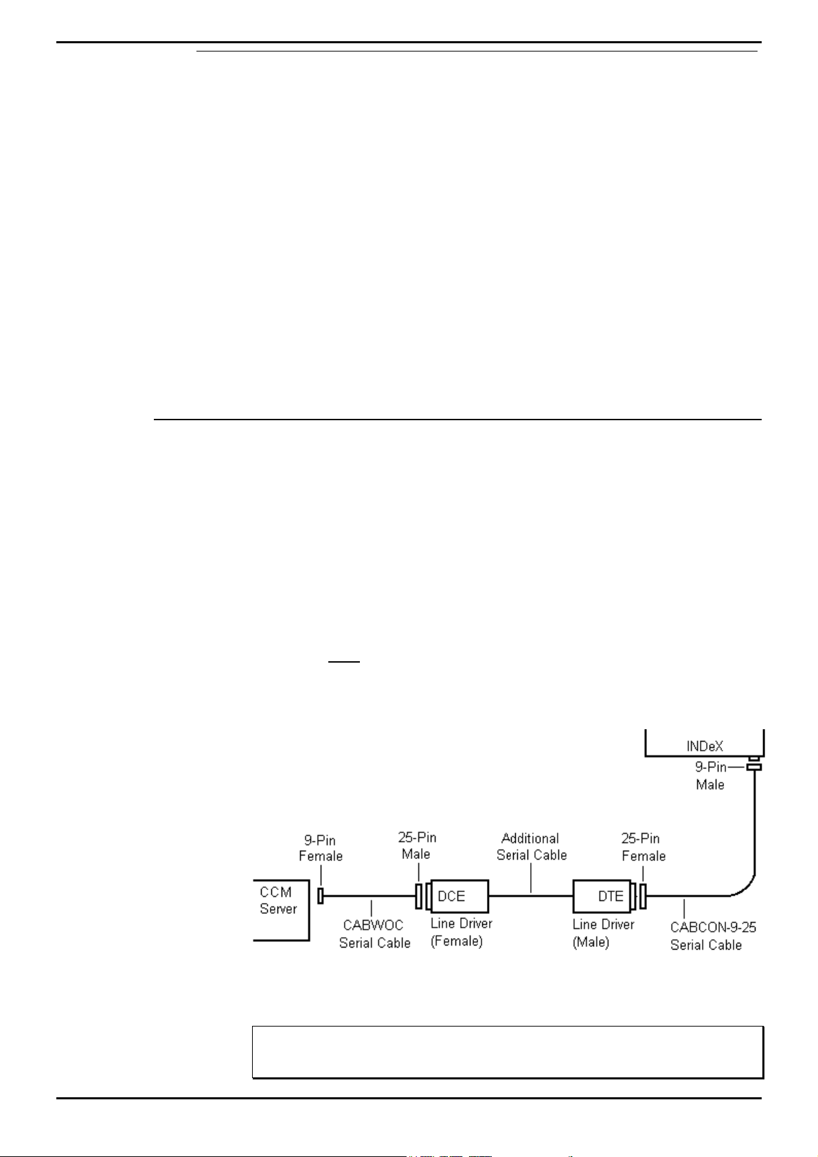
Connecting the INDeX CCM Server
The instructions below assume that you are using cables plus line drivers supplied
by Avaya. You may also require additional serial cable for long cable distances.
1. Connect one end of the CABCON-9-25 cable to a free port on the INDeX control
cabinet (the cabinet containing the CPU Cassette).
– You can use any of the 4 serial sockets on the cabinet. Avoid using the first
(front) socket if possible, as this is required for some INDeX Telephone
System maintenance tasks.
2. The diagram below shows the remaining connections.
– Note the DTE and DCE settings of the line drivers.
– You must connect CABWOC to serial port COM2 of the PC. If this is not a
9-pin port, you need a 9-pin male to 25-pin female serial converter.
– If the cable distances are short, you may connect CABWOC directly to
CABCON-9-25.
Note
The Comms Port default settings on the Access Manager is Port 2. If you use a different
Comms Port, you must also change the Access Manager Comms Port Settings.
INDeX Contact Centre Modules Page 6
Installation & Maintenance 38HBK00001SCM - Issue 11 (05/01)
Page 7

Introduction System Specification
Wallboard Devices
INDeX Wallboard 22
Specification
Voltage 220/240V AC OR 110V AC
(Check label on rear of wallboard)
Wattage 108W
Cold Start Inrush Current 30A for up to 6ms
Baud Rate 9600 only
Input RS 485
Weight 6 kg
Dimensions L 1097 x D 75 x H 198 mm
Installation power distribution circuit rating to be greater than 6 amp, any circuit
breakers must be capable of handling the cold start inrush current without tripping.
For details of INDeX Wallboard 22 Installation see "INDeX Wallboard 22" on page
95.
INDeX Wallboard 10
Specification
Voltage Check label on rear of wallboard
Wattage 35W
Cold Start Inrush Current 30A for up to 6ms
Baud Rate 9600 only
Input RS 485
Weight 4 kg
Dimensions L 469 x D 75 x H 123 mm
Installation power distribution circuit rating to be greater than 6 amp, any circuit
breakers must be capable of handling the cold start inrush current without tripping.
For details of INDeX Wallboard 10 Installation see "INDeX Wallboard 10" on page
102.
INDeX Contact Centre Modules Page 7
Installation & Maintenance 38HBK00001SCM - Issue 11 (05/01)
Page 8

Introduction System Specification
LAN Utilisation
The following results should be interpreted for each customer Network. Use this
only as a guideline.
The network of 1 Server and 9 Clients was defined as follows:
10 Base-T Ethernet: max. capacity (i.e. 100%) = 1220Kbytes/sec
= 9.76Mbits/sec
The LAN was made up of three 8-port Hubs up-linked together.
INDeX Call Centre View Individual Start-Up Results
No. of Clients Average Utilisation
(No Activity)
10.5%5%
2 0.7% 12%
3 1.2% 18%
4 1.5% 24%
5 1.7% 30%
6 2.0% 32%
7 2.3% 36%
8 2.7% 40%
9 3.0% 45%
Peak Utilisation
From the results the following was concluded:
– Peak approx.: 4 to 6% greater as each client is logged on.
– Utilisation peaks at approx.: 63% if all statistics are reset with 9 clients logged
on running INDeX Call Centre View and INDeX Wallboard Client.
– Log-off peak: 0.5%.
Call Loading/Utilisation Results
Duration Call Load
Calls/hour
15 min 10200 70 30% 45%
15 min 8500 70 30% 42%
15 min 6200 70 22% 38%
15 min 4500 70 20% 34%
INDeX Contact Centre Modules Page 8
Installation & Maintenance 38HBK00001SCM - Issue 11 (05/01)
No. of Agents Average
Utilisation
Peak Utilisation
Page 9
Introduction Limitations
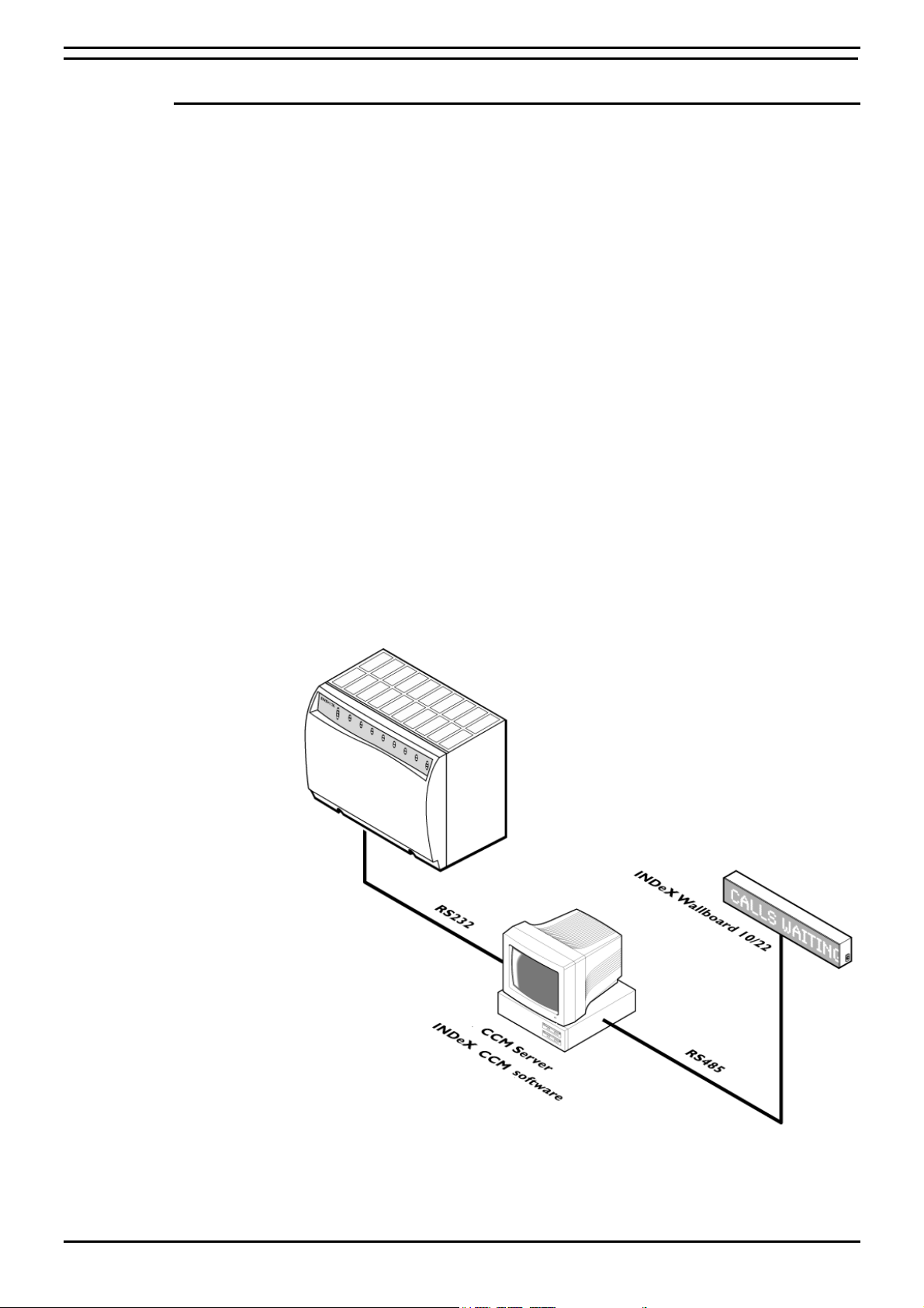
Limitations
15 Agent Systems and below
The INDeX Contact Centre Manager comprises a suite of tightly integrated Contact
Centre Modules installed on an INDeX CCM Server PC platform running Windows
NT4. The INDeX Contact Centre Manager may be installed either with or without an
INDeX Voice Manager. When installed without the INDeX Voice Manager, the
INDeX Contact Centre Manager may be connected directly to one of the INDeX
RS232 ports. Where INDeX Voice Manager is present, the INDeX Contact Centre
Manager is connected via the LAN to the INDeX CT Server Cassette. The following
lists the Contact Centre modules included within the INDeX Contact Centre
Manager which are designed to run concurrently on the INDeX CCM Server PC: -
CCM Server PC
• INDeX Call Centre View.
• INDeX Wallboard Server.
• INDeX Report Server and Client.
• INDeX Report Designer (optional).
• INDeX Taskbar.
• INDeX Networked Administrator.
• INDeX Voice Processing Administration (if INDeX Voice Manager is present).
The following diagram shows the INDeX Contact Centre Manager connectivity, for
systems of 15 agents and below, supplied on a standalone PC from Avaya without
an INDeX Voice Manager.
INDeX Contact Centre Modules Page 9
Installation & Maintenance 38HBK00001SCM - Issue 11 (05/01)
Page 10
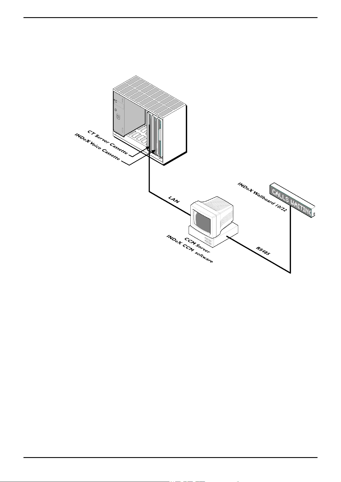
Introduction Limitations
The following diagram shows the INDeX Contact Centre Manager connectivity, for
systems of 15 agents and below, where an INDeX Voice Manager is present.
INDeX Contact Centre Modules Page 10
Installation & Maintenance 38HBK00001SCM - Issue 11 (05/01)
Page 11

Introduction Limitations
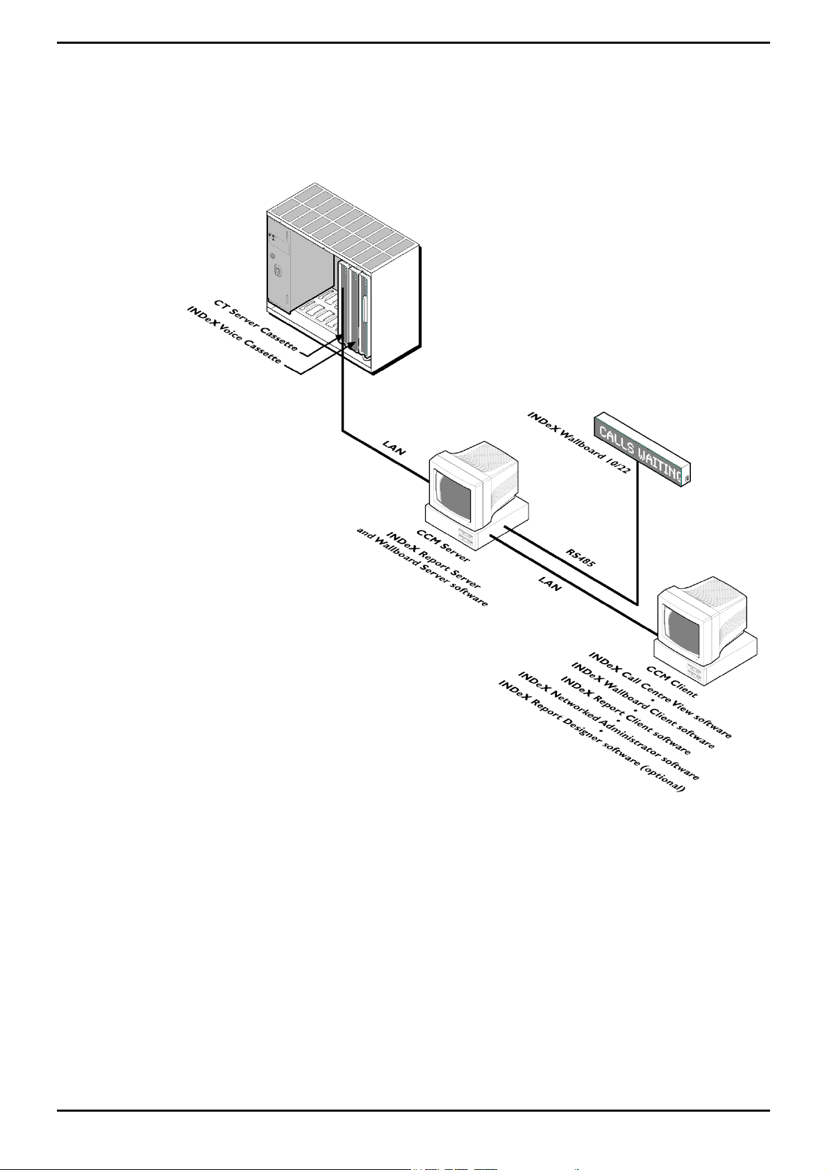
Systems above 15 Agents
Due to the traffic demands of Contact Centre's above 15 agents, the Report Server
and Wallboard Server must reside on a dedicated PC. The product is offered as a
complete solution supplied on 2 PC’s, capable of being installed on the customer’s
existing LAN. Server Applications require Windows NT4 PC’s, however Client
applications are supported on Windows 95/98/2000 in addition to Windows NT4
Workstation.
The INDeX Contact Centre Manager supports the following concurrent supervisor
positions:
CCM SPC5: 5 Supervisor (client) Positions
CCM SPC10: 10 Supervisor (client) Positions
CCM SPC20: 20 Supervisor (client) Positions
The INDeX Contact Centre Manager may be installed either with or without an
INDeX Voice Manager. When installed without an INDeX Voice Manager the
INDeX CCM Server PC is connected directly to one of the INDeX RS232 ports.
Where an INDeX Voice Manager is present, the INDeX CCM Server PC running the
server applications is connected via the LAN to the INDeX CT Server Cassette. The
other applications run on the supervisors Desktop on either an Avaya supplied CCM
Client PC, or an existing Windows 95/98/2000 or Windows NT4 Workstation PC.
The following details where the applications reside:
INDeX CCM Client PC
• INDeX Call Centre View
• INDeX Wallboard Client
• INDeX Report Client
• INDeX Report Designer (Optional)
• INDeX Taskbar
• INDeX Voice Processing applications (if INDeX Voice Manager is present)
INDeX CCM Server PC
• INDeX Report Server
• INDeX Wallboard Server
• INDeX Networked Administration
• INDeX Call Centre View
• INDeX Taskbar
INDeX Contact Centre Modules Page 11
Installation & Maintenance 38HBK00001SCM - Issue 11 (05/01)
Page 12
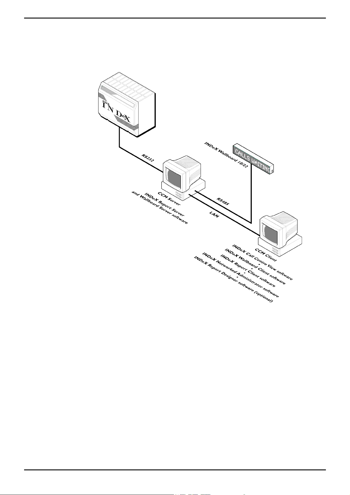
Introduction Limitations
The diagram below shows the INDeX Contact Centre Manager without an INDeX
Voice Manager being installed.
INDeX Contact Centre Modules Page 12
Installation & Maintenance 38HBK00001SCM - Issue 11 (05/01)
Page 13
Introduction Limitations
The diagram below shows the INDeX Contact Centre Manager where an INDeX
Voice Manager is present.
INDeX Contact Centre Modules Page 13
Installation & Maintenance 38HBK00001SCM - Issue 11 (05/01)
Page 14

PC Configuration Overview
PC Configuration
Overview
The INDeX CCM Server PC requires a 2 GB partition for the software applications.
The remaining of the hard drive is used for the INDeX Archiver database. During
the Windows NT 4.0 installation, ensure the 2 GB partition is formatted as FAT.
This section details the PC configurations as follows:
1. Server PC (SPC20) configuration using Windows NT 4.0 Server – (Supporting
Max 20 Clients). See page 15.
2. Server PC (SPC5/10) configuration using Windows NT 4.0 Server – (Supporting
5 or 10 Clients respectively). See page 37.
3. Client PC configuration using Windows NT 4.0 Workstation. See page 39.
4. Client PC configuration using Windows 98. See page 43.
INDeX Contact Centre Modules Page 14
Installation & Maintenance 38HBK00001SCM - Issue 11 (05/01)
Page 15

PC Configuration Server PC – SPC20 (Max 20 Clients)
Server PC – SPC20 (Max 20 Clients)
This section details the following procedures required to prepare the Server PC
(supporting Max of 20 Clients) to install INDeX CCM applications.
• Install Windows NT Server 4.0 .
• Install Service Pack 6a.
• Create NTFS Partition using Disk Administrator (different for SPC5 and SPC10).
• Install Display Adapter.
• Install EtherLink PCI Network Interface Card.
• TCP/IP Networking Setup.
• Install ADR OnStream Tape Drive.
• Install Advantech PCI Wallboard Comms Card.
• Install Microsoft SQL Server 7.0.
• Install ODBC (Open Database Connectivity).
• Windows NT Server Modifications.
The same procedure is required when configuring INDeX CCM SPC5 and SPC10
Server PCs with the exception of the Disk Administrator (NTFS partition), as
detailed in “Server PC Setup – SPC5/10” on page 37.
Install Windows NT Server 4.0
1. Insert Windows NT Server CD-ROM and Windows NT Setup Disk 1 and reboot
the PC.
2. When prompted, insert Windows NT Setup Disk 2 and press Enter.
3. Press Enter "To setup Windows NT now".
4. Press Enter to attempt to detect Mass Storage Devices in your PC.
5. When prompted, insert Windows NT Setup Disk 3 and press Enter to continue.
6. Press Enter to confirm that there is only one CD ROM storage device.
7. Press Page Down until you reach the end of the Licensing Agreement text and
then press F8 to agree.
8. With the Keyboard Layout: US highlighted, press Enter and then select United
Kingdom, to change the Keyboard Layout from US to United Kingdom.
9. With "The above list matches my computer" highlighted, press Enter.
10. You may have to delete the existing partitions before you are able to create the
2000 MB partition on the C: drive.
11. With "Create partition of size (in MB): 2000" highlighted, press Enter.
12. Press Enter again to continue.
13. Select Format the Partition using FAT file system and press Enter to format the
partition.
14. At \WINNT press Enter for this directory.
15. Press Enter to carry out an exhaustive search. Setup files will now be copied to
the PC.
16. When asked, remove the floppy disk (leaving the Windows NT CD in the CDROM Drive) and press Enter.
19. The PC restarts presenting a Windows NT Setup Wizard from which click Next.
20. Type your Name as Administrator and your Organisation, click Next.
21. Enter the CD Key (from the yellow sticker on the back of the Windows NT CD
case) for Registration, click Next.
INDeX Contact Centre Modules Page 15
Installation & Maintenance 38HBK00001SCM - Issue 11 (05/01)
Page 16

PC Configuration Server PC – SPC20 (Max 20 Clients)
22. Enter the correct number of Client Access License and then click Next.
– For CCM SPC5 – 5
– For CCM SPC10 – 10
– For CCM SPC20 – 20
23. Type Computer Name as ARCHIVERSQL and click Next.
24 Select Stand-Alone Server as the "Server Type" and click Next.
25. Enter the Password fields as required and then click Next.
26. From the "Emergency Repair Disk" screen, select "No, do not create an
emergency repair disk" and click Next.
27. From the "Select Components" screen, leave the default selection and click
Next.
28. With 2) Installing Windows NT Networking selected, click Next.
29. Click to select “Do not connect this computer to a network at this time”, click
Next.
Note
Installing the Network Interface Card is detailed in “Install EtherLink PCI Network
Interface Card” on page 23.
30. Click Finish to complete the setup.
31. From the Date/Time Properties screen, ensure Time Zone is set to the local time
[e.g. for UK set it to English (United Kingdom)] and click Close.
32. From the Detected Display screen, click OK and then TEST to test the display
and then click OK.
33. Wait till colour screen closes, from the Testing Mode screen, click Yes and then
OK to save the display settings. From the Display Properties screen click OK.
34. Remove any floppy disks and CDs from the PC, click Restart Computer To
reboot the PC.
35. From the Begin Logon screen press Ctrl+Alt+Delete to log on.
36. From the Logon Information screen, enter the User Name and Password, click
OK.
INDeX Contact Centre Modules Page 16
Installation & Maintenance 38HBK00001SCM - Issue 11 (05/01)
Page 17
PC Configuration Server PC – SPC20 (Max 20 Clients)
Install Windows NT Server Service Pack 6a
Alterations to Windows NT 4.0's configuration including the addition of software,
mean that the Service Pack (containing Microsoft bug fixes), needs to be reapplied.
The same procedure is applicable when reinstalling the Service Pack 6a.
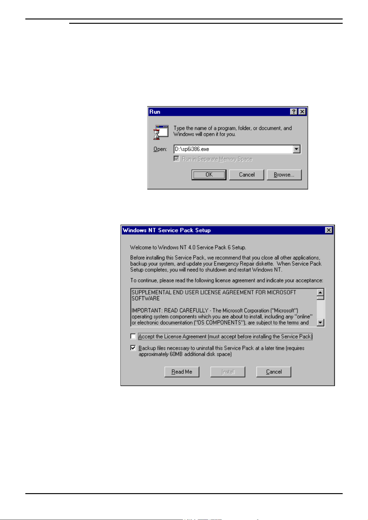
1. Insert the INDeX Application Service Pack CD in the CD ROM Drive, from the
Windows NT desktop, click Start and then select Run. In the Open box type
D:\sp6i386.exe, as shown in the following screen:
2. Click OK, the following screen appears:
3. Click to select "Accept the License Agreement".
4. Click to uncheck "Backup files necessary to uninstall this Service Pack at a
later time".
5. Click Install, the Windows NT Service Pack Setup screen appears to indicate
the installation of the System files on to the PC.
INDeX Contact Centre Modules Page 17
Installation & Maintenance 38HBK00001SCM - Issue 11 (05/01)
Page 18
PC Configuration Server PC – SPC20 (Max 20 Clients)
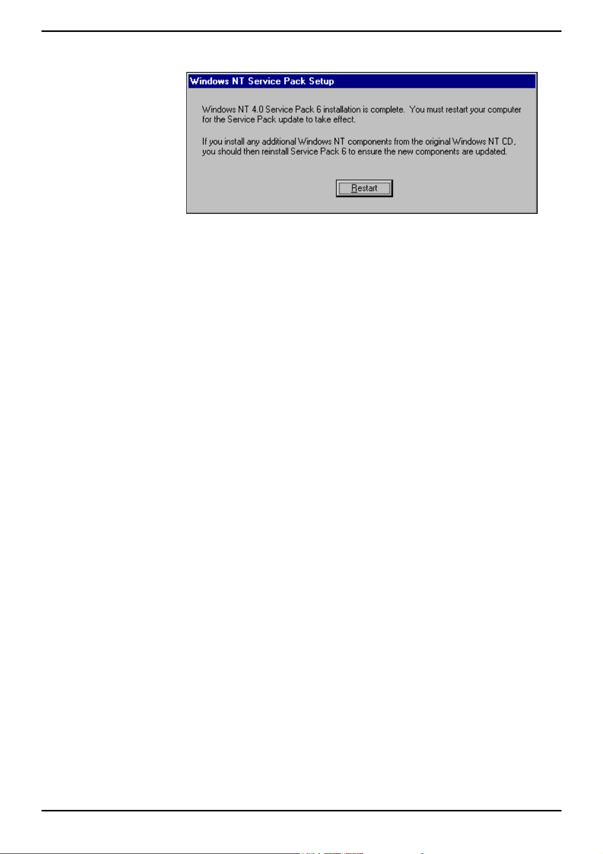
6. Once the installation is complete the following screen appears:
7. Click Restart.
8. Recheck the Regional Setting to ensure it is set to English (United Kingdom).
INDeX Contact Centre Modules Page 18
Installation & Maintenance 38HBK00001SCM - Issue 11 (05/01)
Page 19
PC Configuration Server PC – SPC20 (Max 20 Clients)
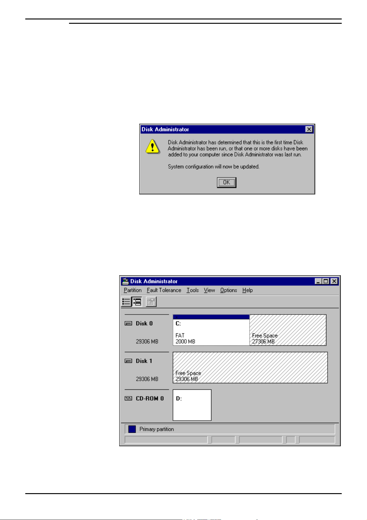
Create NTFS Partition using Disk Administrator
Disk Administrator is a graphical tool for managing disks. This tool encompasses
and extends the functionality of character-based disk management tools such as
MS-DOS FDISK.
This section details the procedure required to create and format the NTFS partition
of the SPC20 hard drive.
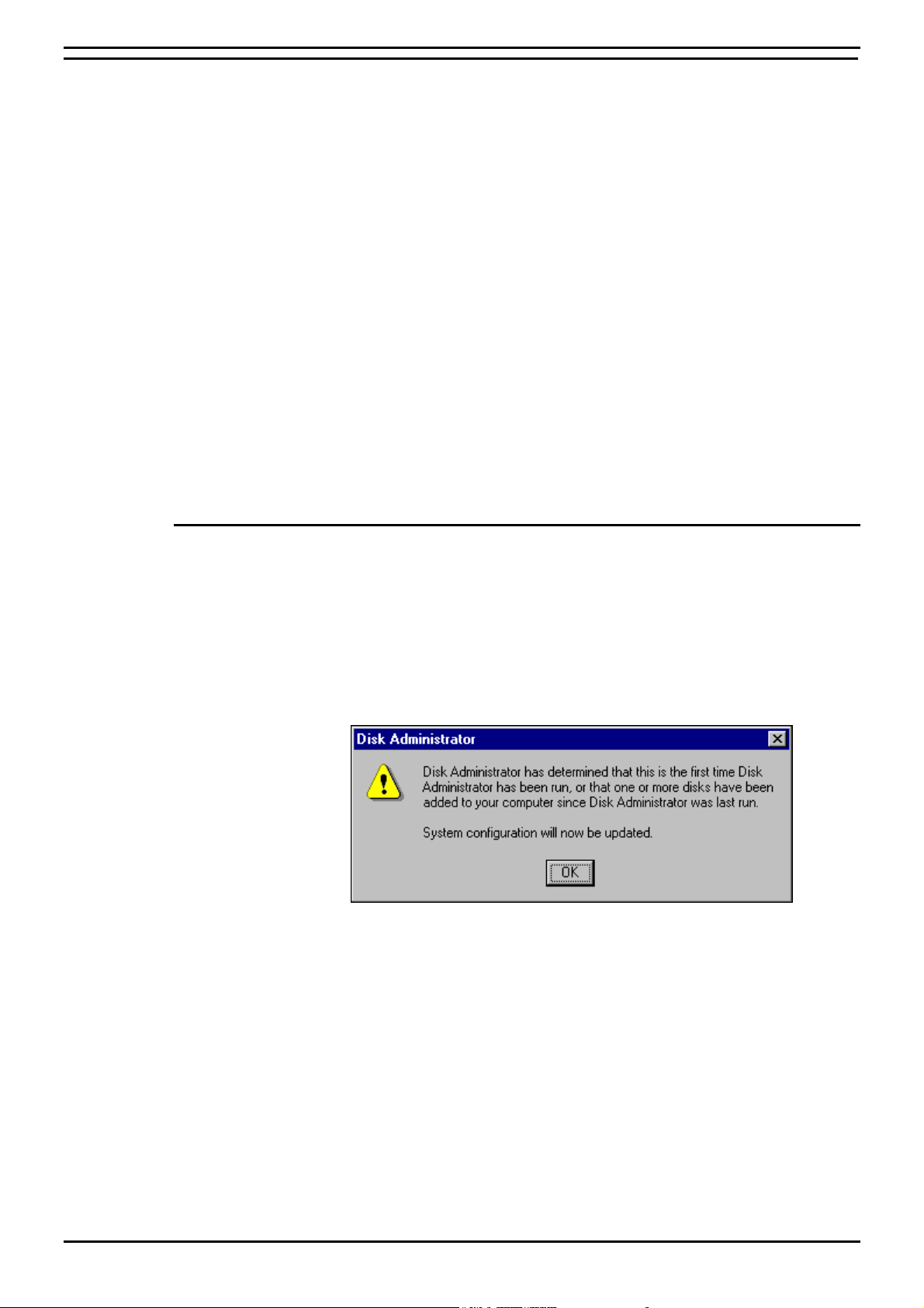
1. From the Windows Taskbar, click Start, point to Programs, point to
Administrative Tools (Common) and click Disk Administrator. When running this
application for the first time, the following screen appears:
2. Click Ok and then OK to the following confirmations.
3. A scrollable, graphical representation of all the physical disks connected to your
computer along with their partition appears. A status bar at the bottom of the
window provides basic information on partitions. A colour-coded legend on top
of the status bar shows what the different partition colours and patterns
represent.
4. Click the D drive (i.e. CD-ROM).
INDeX Contact Centre Modules Page 19
Installation & Maintenance 38HBK00001SCM - Issue 11 (05/01)
Page 20
PC Configuration Server PC – SPC20 (Max 20 Clients)
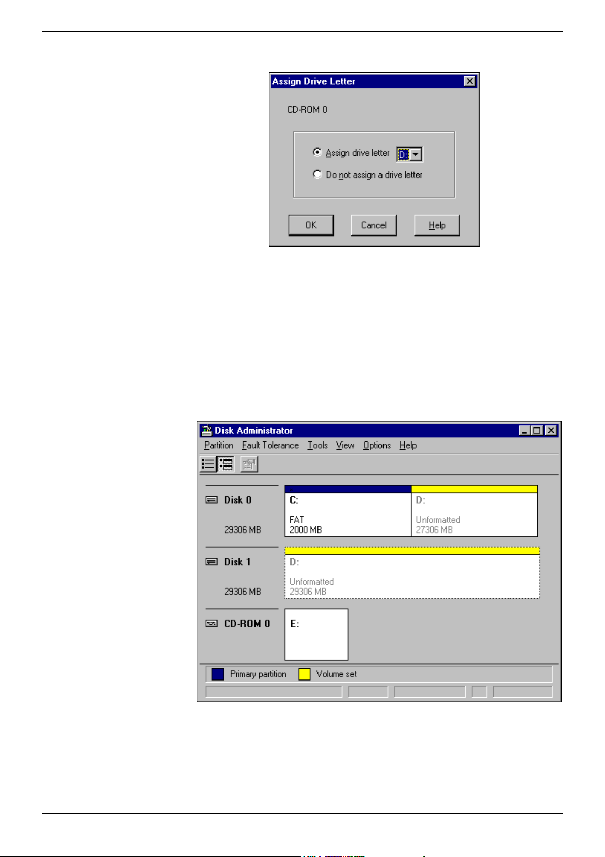
5. From the Tools menu, click Assign Drive Letter, the following screen appears:
6. Click to select Assign Drive Letter, and select letter E.
7. Click OK.
8. From the Confirmation screen, click Yes to continue.
9. To create a Volume Set of the remaining hard drive, select the first area of free
space and then pressing CTRL and click each of the other areas.
10. From the Partition menu, select Create Volume Set. Disk Administrator
displays the minimum and maximum sizes for the volume set.
11. Click OK.
INDeX Contact Centre Modules Page 20
Installation & Maintenance 38HBK00001SCM - Issue 11 (05/01)
Page 21
PC Configuration Server PC – SPC20 (Max 20 Clients)
12. From the Partition menu, select Commit Changes Now, the following screen
appears:
13. Click Yes to save the changes. At the Confirmation screen, click Yes and then
click OK to update the Disks.
14. Click OK to initiate system shutdown.
15. Once the PC has rebooted, from the Windows Taskbar, click Start, point to
Programs, point to Administrative Tools (Common) and click Disk Administrator.
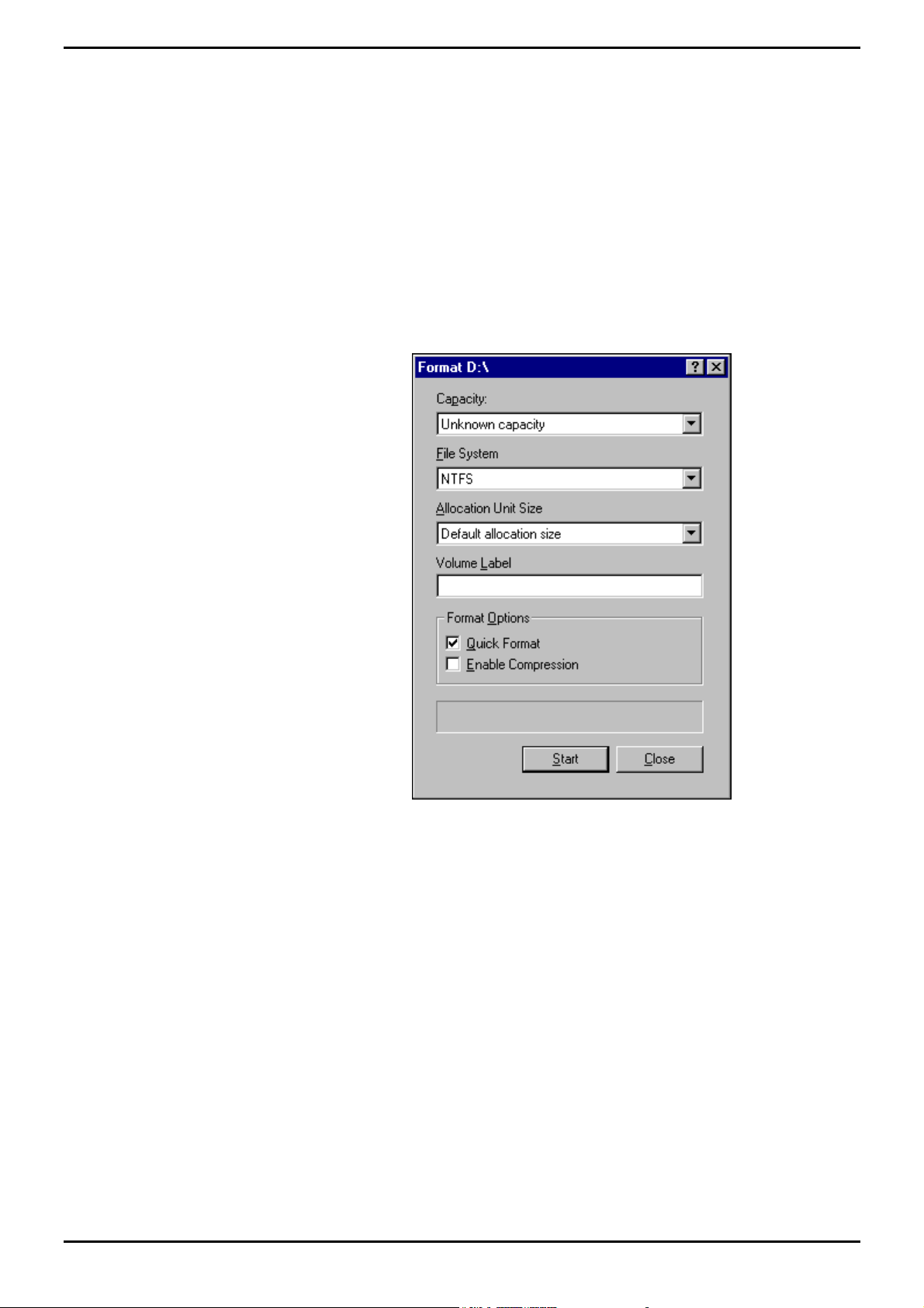
16. Click the newly created drive (i.e. D: drive), from the Tools menu and select
Format.
17. Set File System to NTFS and click to select Quick Format as displayed in the
following screen:
18. Click Start to initiate the format request, the following screen appears:
19. At the Warning screen, Click OK, when the formatting is finished, the following
screen appears:
19. Once formatting is complete, Click OK. From the Format D:\ screen, click Close
to return to the Disk Administrator window.
20. From the Partition menu, click Exit to close the Disk Administrator application.
21. Reboot the PC.
INDeX Contact Centre Modules Page 21
Installation & Maintenance 38HBK00001SCM - Issue 11 (05/01)
Page 22
PC Configuration Server PC – SPC20 (Max 20 Clients)
Install Display Adapter
Since INDeX CCM applications are designed to use a screen resolution of 800 by
600 pixels, it is necessary to install a third party display adapter driver that is not
installed by default when installing Windows NT Server.
1. Insert the Display Adapter CD in the CD Drive, click ATI Easy Install.
2. At the Welcome screen click OK to proceed.
3. At the Software License Agreement click Yes to continue.
4. Click Express: Recommended and then once the Setup has finished copying
files to the PC, click Finish to restart the PC:
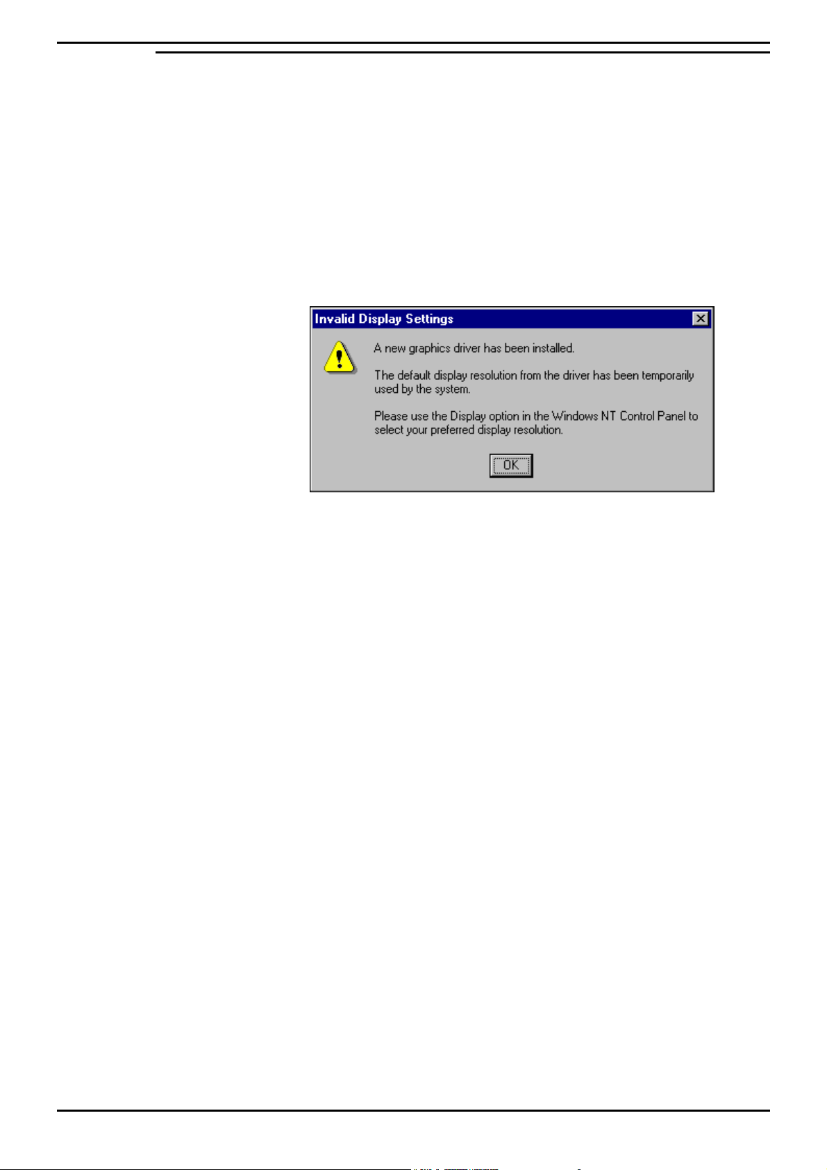
6. Once the PC has rebooted, log back on, the following screen appears:
7. Click OK.
8. From the Display Properties screen set the Desktop Area to 800 by 600 pixels,
and set the Color Palette to 65536, click Test:
9. At the Testing Mode screen, click OK to test the display.
10. Wait till colour screen disappears. From the Test Mode screen, click Yes if the
colours were coherent and then click OK to save the display set up.
11. From the Display Properties screen, click Apply and then click OK
INDeX Contact Centre Modules Page 22
Installation & Maintenance 38HBK00001SCM - Issue 11 (05/01)
Page 23

PC Configuration Server PC – SPC20 (Max 20 Clients)
Install EtherLink PCI Network Interface Card
There are four steps to the Network Interface Card (NIC) installation:
a) Run the pre-installation program before installing the NIC in the PC.
The EtherCD pre-installation program prevents conflicts with the NIC and your
operating system. It guides you through the NIC installation and must be run
before you physically install the NIC in the PC.
b) Install the NIC in the PC.
c) Connect the NIC to the network.
d) Install the network driver.
Note
If there is network card in the PC, you must remove the Network card and the associated
software from the PC.
a) Run the Pre-installation Program
Before you physically install the NIC in a PC, run the NIC pre-installation program to
properly set up your system environment.
The pre-installation program prevents conflicts with the NIC and your operating
system. It guides you through the NIC installation and must be run before you
physically install the NIC in the PC.
To run the NIC pre-installation program:
1. Do NOT install the NIC in the PC.
2. Turn on the power to the PC and start Windows.
3. Quit any open applications and disable the automatic protection feature of any
anti-virus software that may be running.
4. Insert the EtherCD in the CD-ROM drive.
The EtherCD Welcome screen appears. If the EtherCD Welcome screen does
not appear, enter the following command from the Run option of the Windows
Start menu: X:\installs\setup.exe where X:\ represents the letter of the CD-ROM
drive.
5. Click NIC Software.
6. Click NIC Drivers and Diagnostics.
7. Click Install NIC Driver.
To install the network driver and the 3Com NIC Diagnostics program, click
Install with Diagnostic Program. (We recommend you select this option).
To install the network driver only, click Install without Diagnostic Program.
Files are copied. A message box appears when the installation is complete.
8. Click OK.
9. Select your operating system (Windows NT) to continue the installation.
The Completing NIC Installation screen appears.
10. Click Done.
11. Exit the EtherCD, and then shut down Windows.
12. Turn off the power to the PC.
INDeX Contact Centre Modules Page 23
Installation & Maintenance 38HBK00001SCM - Issue 11 (05/01)
Page 24

PC Configuration Server PC – SPC20 (Max 20 Clients)
b) Install the NIC in the PC
To install the NIC in the PC:
1. Make sure that you have run the pre-installation program, as described in the
previous section.
2. Turn off the power to the PC and unplug the power cord.
3. Remove the cover from the PC.
4. Locate an empty, non-shared bus-mastering PCI slot and remove its slot cover.
Save the screw.
Do not install the NIC in a shared PCI slot. Avoid any PCI slot next to an ISA
slot. This is often a shared slot and does not support bus mastering.
5. Carefully insert the NIC in the empty PCI slot. Press firmly to ensure that the
NIC is fully seated in the slot.
6. Secure the NIC with the screw you removed earlier.
7. Replace the PC cover and plug in the power cord.
Do NOT turn on the power to the PC.
c) Connect the NIC to the Network
Connect the appropriate network cable to the NIC provided by the Network
Administrator of the Customer’s Site.
d) Install the Network Driver
To install the network driver:
1. Turn on the power to the PC.
2. Double-click the My Computer icon, then the Control Panel icon and then the
Network icon. The Network window appears.
3. Click the Adapters tab. If networking has not been installed on your PC before,
Windows NT asks you if you want to install networking. Click Yes. See the
WINNT.TXT file located on the EtherCD or your Windows NT documentation for
instructions.
4. Click Add. The Select Network Adapter dialog box appears.
5. Click Have Disk. The Insert Disk dialog box appears.
6. Insert the EtherCD in the CD-ROM drive.
7. Make sure that the letter of the CD-ROM drive (for example, e:\ appears in the
entry box, and then click OK. The Select OEM Option dialog box appears.
8. Make sure that the 3Com EtherLink PCI NIC is selected, and then click OK.
The Adapters tab of the Network screen appears.
9. Click Close. If the Microsoft TCP/IP Properties screen appears, enter the
requested information for your network environment. Refer to your Network
System Administrator or the Windows NT documentation for assistance. If the
Microsoft TCP/IP Properties screen does not appear, the installation is
complete.
10. Click Yes to restart the PC. The network driver installation is complete.
You are now ready to adjust the Networking Setup according to the Customer’s
Network; i.e. either TCPIP or IPX/SPX as detailed in following pages.
INDeX Contact Centre Modules Page 24
Installation & Maintenance 38HBK00001SCM - Issue 11 (05/01)
Page 25

PC Configuration Server PC – SPC20 (Max 20 Clients)
TCP/IP Networking Setup
The process of configuring the INDeX CCM Server PC to use TCP/IP consists of the
following stages.
1. Check the TCP/IP settings required, these should be supplied by the customer
Network Manager, for example:
– IP Address.
– Subnet mask.
– Default gateway.
2. Re-configure Server/Client PC to TCP/IP.
3. Allow the Server PC and Client PCs to restart and then check the connection.
Changing a Server/Client PC to TCP/IP
The following process may require you to have the original Windows NT4
Server/Workstation CD available. It will also require the PC to be restarted after
completion. The following procedure applies to both Server PC and the Windows
NT Client PC.
1. Right-click the Network Neighborhood icon and select Properties.
2. Click the Adapters tab to check that the PC's network card is listed.
– If the network card is not shown, refer to the manufacturers supplied
information for correct installation.
3. Click the Protocols tab. Check that TCP/IP Protocol is shown. If not shown
then use the process below to install the protocol.
– Click on Add and select TCP/IP Protocol. After installation, the list of
protocols should include TCP/IP Protocol.
4. Click the Bindings tab, then return to the Protocols tab.
5. Highlight TCP/IP Protocol and click Properties. Add the settings specified by
the customer's Network Manager and then click on OK.
6. Click OK and allow the PC to restart.
INDeX Contact Centre Modules Page 25
Installation & Maintenance 38HBK00001SCM - Issue 11 (05/01)
Page 26
PC Configuration Server PC – SPC20 (Max 20 Clients)
IPX/SPX Frame Type Networking Setup
This is applicable if the Customer Site Network uses IPX Frame Type.
1. From the Windows taskbar, click Start, point to Settings and select Control
Panel.
2. From the Control Panel, open Network, click the Protocols tab.
3. With the NWLink IPX/SPX Compatible Transport selected, click Properties.
This represents three scenarios:
– If a Novell NetWare Server is present on the network, ensure the
CCM Server PC uses the same frame type as NetWare Server.
– If a Server Cassette (Voice) is on the network, ensure the CCM
Server PC uses the same frame type as Server Cassette (the required
settings for INDeX CCM is Ethernet II).
– If no other servers are on the network, ensure that all PCs running
INDeX products are using the same frame type.
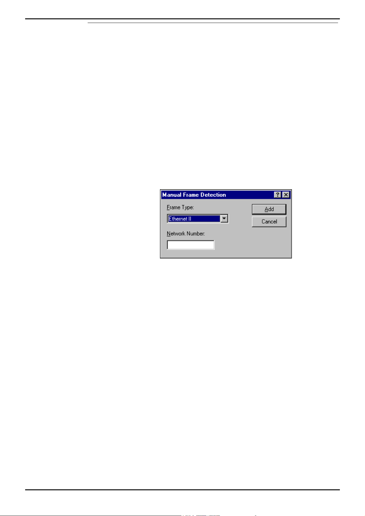
4. Click Properties.
5. Click Add and select Ethernet II as the Frame Type as displayed in the
following screen:
6. Click Add.
7. From the NWLink IPX/SPX Properties screen click Apply and then OK.
8. Click Yes to restart the PC.
INDeX Contact Centre Modules Page 26
Installation & Maintenance 38HBK00001SCM - Issue 11 (05/01)
Page 27
PC Configuration Server PC – SPC20 (Max 20 Clients)
Install ADR OnStream Tape Drive
1. Ensure the Tape Drive unit is installed in the PC according to the Manufacture’s
instructions (Installing the Hardware section).
2. Once the PC is rebooted and you have logged on, insert the ADR Installation
CD in to the CD ROM Drive. Close the OnStream CD Setup Window.
3. From the Windows taskbar, click Start, point to Settings and select Control
Panel.
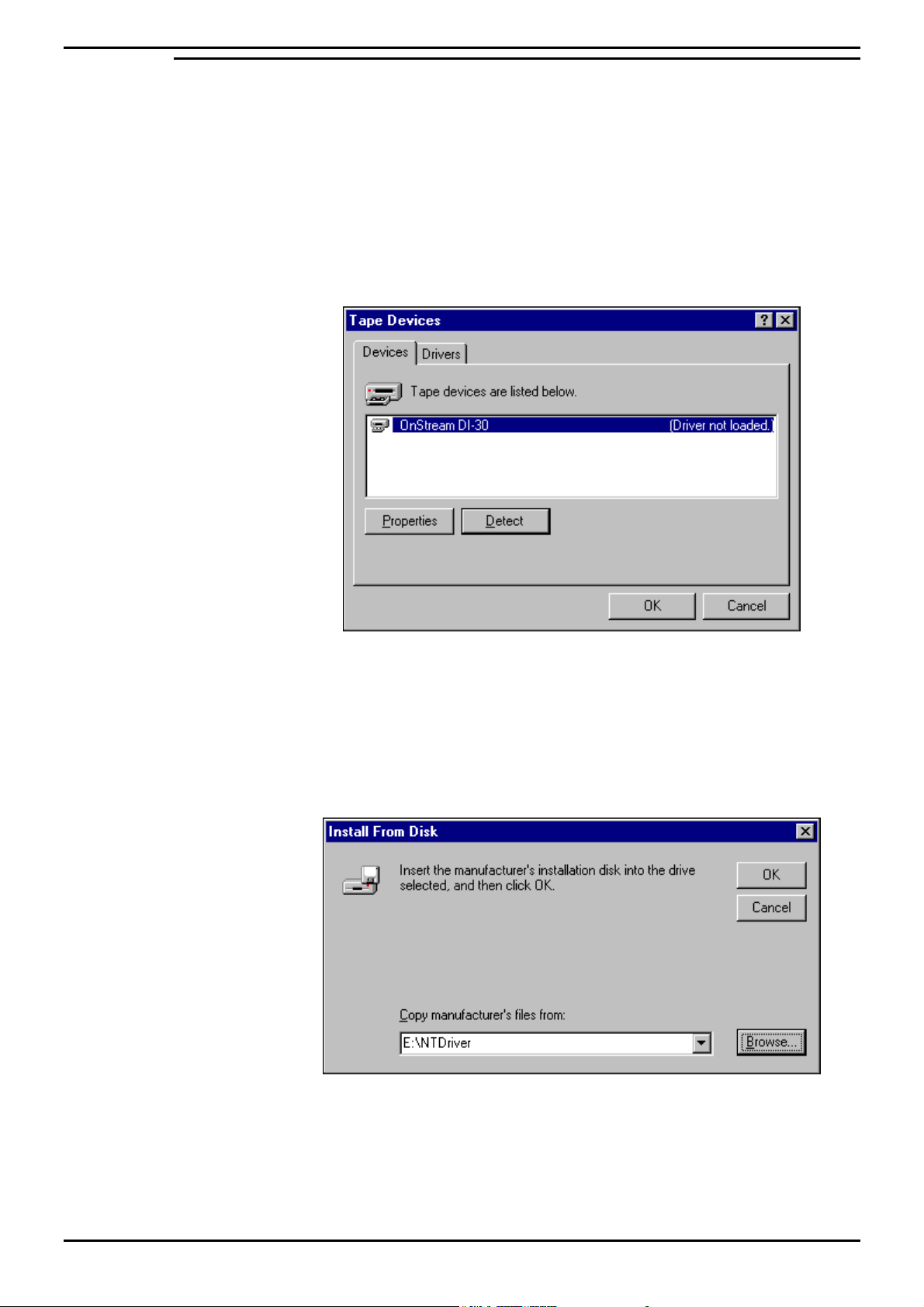
4. From the Control Panel, double click Tape Devices, the following screen
appears:
5. Click Detect. Once the tape drive has been detected, click the Drivers tab, from
which screen click Add.
6. From the Install Driver screen, click Have Disk, click Browse, and then select the
Path “X:\NT Driver”, where X is the drive letter associated with the CD ROM
Drive.
7. Click OK. With the Tape Drive selected, click OK. Once the tape driver is
installed click OK.
8. Tape Devices screen will now display the details for the newly installed driver.
Click OK to close the screen. Click Yes to restart the PC. The Tape drive is
now ready for use.
INDeX Contact Centre Modules Page 27
Installation & Maintenance 38HBK00001SCM - Issue 11 (05/01)
Page 28
PC Configuration Server PC – SPC20 (Max 20 Clients)
Install Advantech PCI Wallboard Comms Card
Before installing the Wallboard Comms card in to the system, you must install the
driver first. Once the driver is installed, check the card jumpers and Switch locations
are set as detailed in this section.
1. Ensure the card is NOT plugged in to the PC.
2. Insert the Advantech installation diskette #1 into drive A:\.
3. From the Windows NT desktop, click Start and then select Run. In the Open
box type A:\Setup.exe.
4. Click OK to proceed. At the Welcome screen click Next. From the Software
License Agreement screen click Yes to continue.
5. From Choose Destination Location screen, click Next to continue.
6. From Select Program Folder screen, click Next to continue.
7. When prompted, insert diskette #2 in to drive A:\.
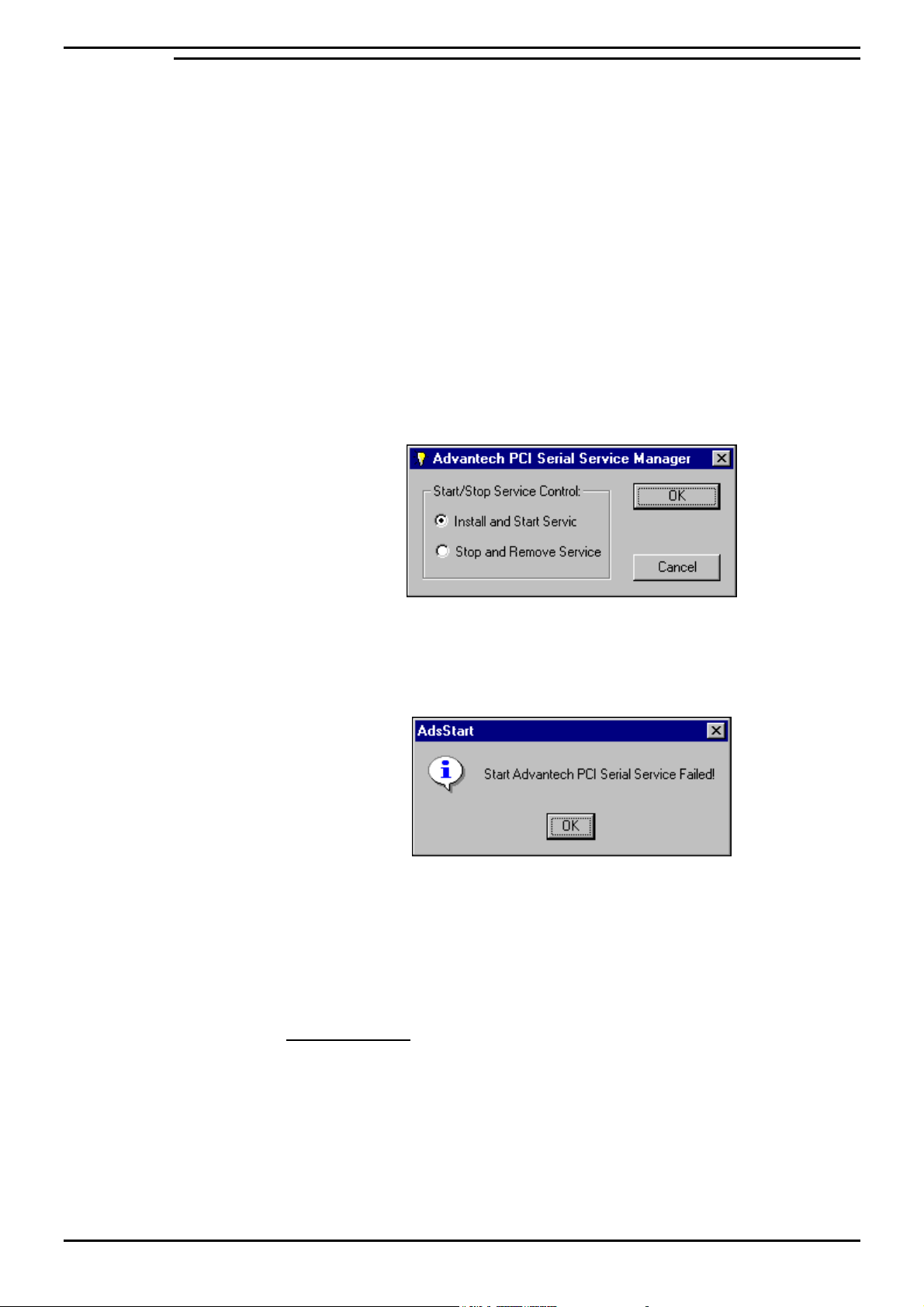
8. Click Finish to complete the Setup, the following screen appears:
9. With Install and Start Service selected, click OK.
10. When the files have been copied, the following screen appears:
11. Click OK.
12 Switch the PC off.
13. Plug the Card in to a free PCI slot with the following Jumper Settings. Switch
the PC on.
Jumper Settings:
– Set Jumpers JP1 and JP2 to 485
– Set Channels 1 & 2 Dip Switches to ‘ON’.
After the PC is restarted, reinstall Service Pack 6a as detailed in “Install Windows
NT Server Service Pack 6a” on page 17.
INDeX Contact Centre Modules Page 28
Installation & Maintenance 38HBK00001SCM - Issue 11 (05/01)
Page 29
PC Configuration Server PC – SPC20 (Max 20 Clients)
Install Microsoft SQL 7.0
Microsoft SQL is a database application that is installed to store data for use with
the INDeX Archiver. It also provides a means of administering the related database
services (e.g. Backup and Restoring of the database).
1. Insert the Report Manager Database CD in the CD Drive. Microsoft SQL
Server Automenu screen appears.
You must ensure if there are any prerequisites (i.e. Internet Explorer 4.01
Service Pack 1) are needed, before installing SQL Server 7.0 components
2. If Internet Explorer 4.01 Service Pack 1 is not loaded on the PC, click Install
SQL Server 7.0 Prerequisites. Select Windows NT, select Launch Setup Wizard
and then follow the instructions on the Internet Explorer 4.01 SP1 Active Setup
wizards to install the application.
3. Once the above is complete, from the Microsoft SQL Server Automenu screen
click Install SQL Server 7.0 Components.
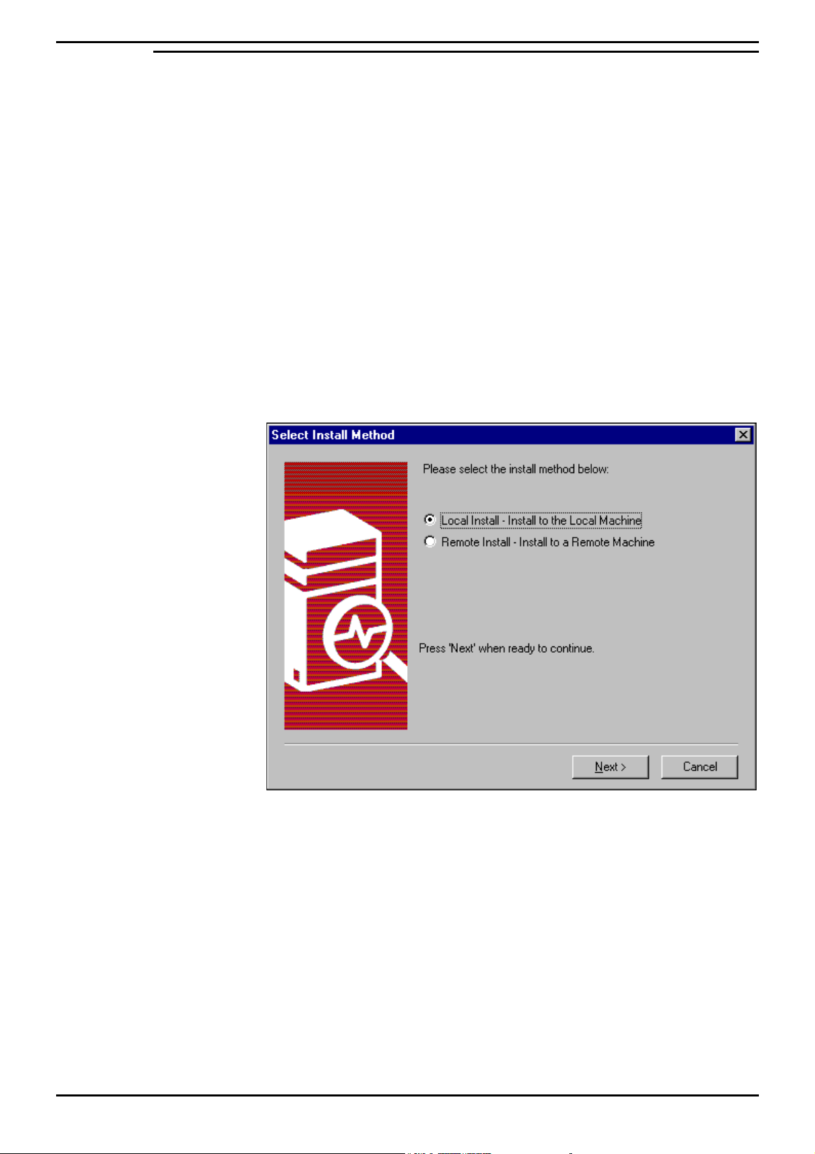
4. From the Install SQL Server 7.0 Components screen select Database Server –
Standard Edition, the following screen appears:
5. Click Next to proceed to the Welcome screen, from which click Next to proceed.
INDeX Contact Centre Modules Page 29
Installation & Maintenance 38HBK00001SCM - Issue 11 (05/01)
Page 30
PC Configuration Server PC – SPC20 (Max 20 Clients)
6. From the Software License Agreement screen click Yes to proceed to the
following screen:
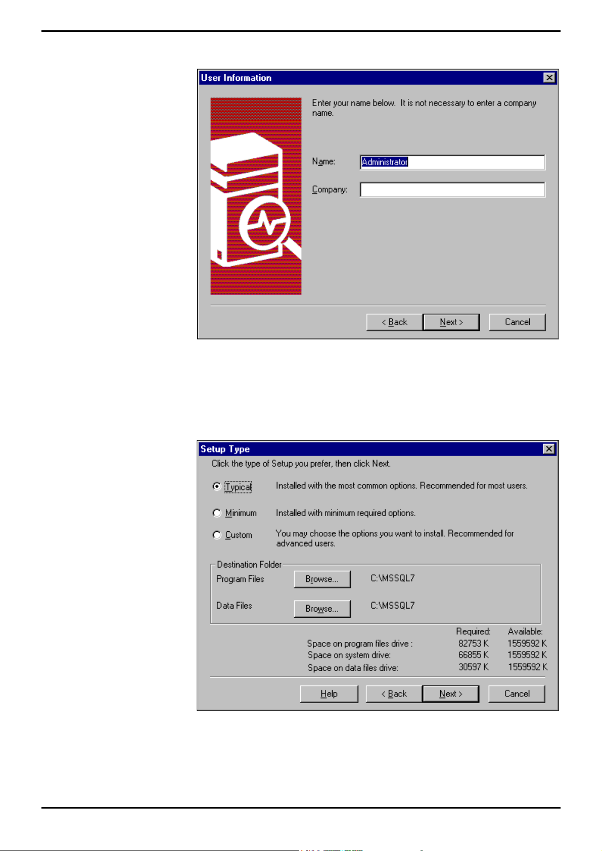
7. Enter the Name as Administrator and your Organisation's name and then click
Next to proceed.
8. Enter the “10 digit CD Key” and then click OK to proceed.
9. Take a record of the Product ID number, as you will be asked for this number if
you need to call Microsoft for Technical Support. Click OK to proceed to the
following screen:
10. Select Typical.
INDeX Contact Centre Modules Page 30
Installation & Maintenance 38HBK00001SCM - Issue 11 (05/01)
Page 31
PC Configuration Server PC – SPC20 (Max 20 Clients)
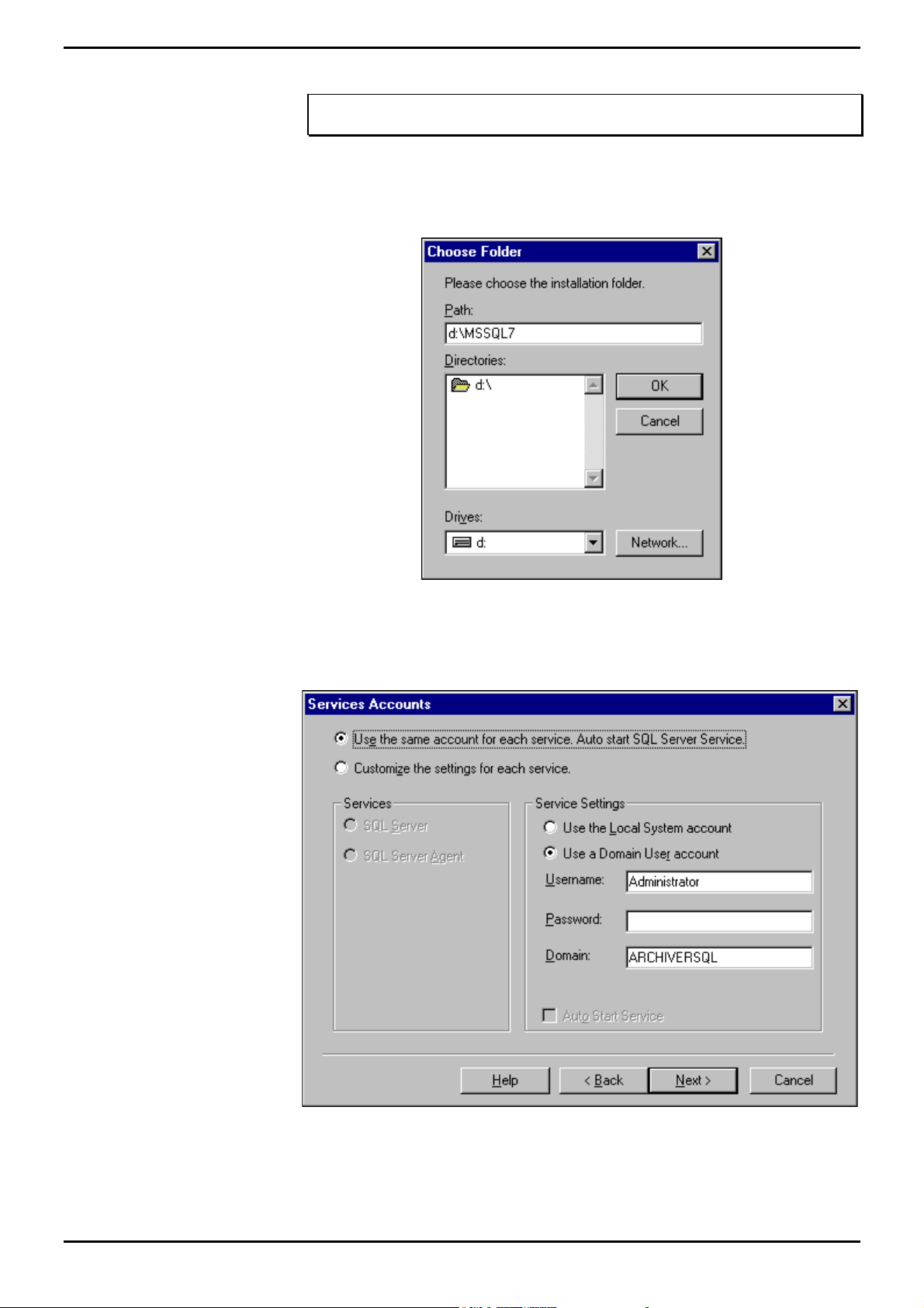
11. Click Browse associated with Data Files.
Note
It is ESSENTIAL that Data Files are saved in the D DRIVE
12. Select the D Drive and type D:\MSSQL7 in the Path text box, as displayed in the
following screen:
13. Click OK and the from Setup Type screen click Next to proceed to the following
screen:
14. Click “Use the Local System account", then click Next, and then click Next
again to proceed to the Choose Licensing Mode screen.
INDeX Contact Centre Modules Page 31
Installation & Maintenance 38HBK00001SCM - Issue 11 (05/01)
Page 32
PC Configuration Server PC – SPC20 (Max 20 Clients)
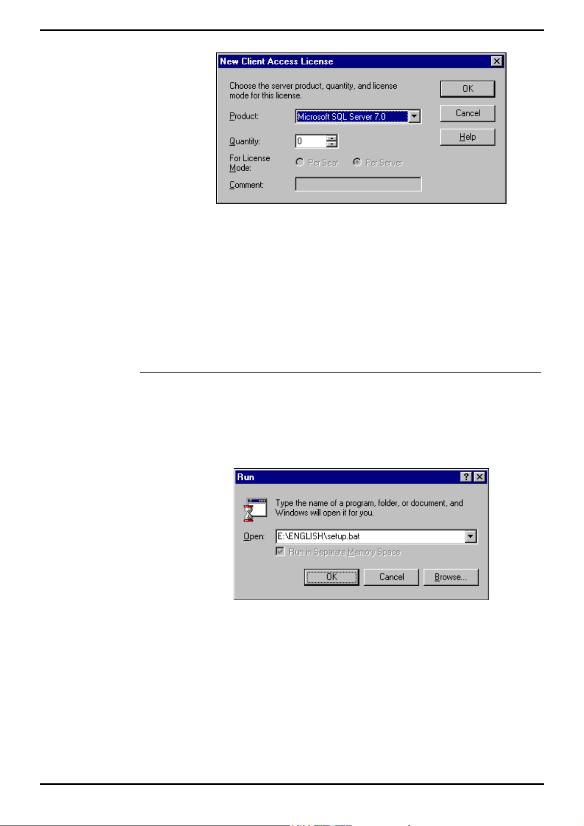
15. Click Add Licenses the following screen appears:
16. Enter the number of purchased licenses.
17. Once you have selected the required Server License Quantities, click OK to the
Per Server Licensing screen, from which click to select “I agree that” and then
from the Choose Licensing Mode screen click Continue.
18. From Client Licensing screen, click to select “I agree that” and then click OK to
proceed.
19. Click Finish to complete the Setup.
20. Once the PC is rebooted, the ARCHIVERSQL Server will automatically be
registered.
Install Microsoft SQL 7.0 Service Pack 1
Alterations to Microsoft SQL's configuration, mean that the Service Pack (containing
Microsoft bug fixes), needs to be applied.
1. Insert the CD in the CD ROM Drive, from the Windows NT taskbar click Start,
select Run, and type X:\English\setup.bat, as displayed in the following screen
(X is the letter associated with the CD Drive of the PC):
2. Click OK.
3. From the Welcome screen, click Next to proceed.
4. From the Software License Agreement screen, click Yes to continue.
5. Click to select “The SQL Server system administrator login information (SQL
Server authentication)”, leaving the password field blank.
6. Click Next to proceed.
7. Click Next to begin copying the files.
8. Once Setup has finished copying the files to the PC click Finish to restart the
PC.
Once the PC has been restarted, the SQL Server will be operational with the
Service Pack fully installed.
INDeX Contact Centre Modules Page 32
Installation & Maintenance 38HBK00001SCM - Issue 11 (05/01)
Page 33
PC Configuration Server PC – SPC20 (Max 20 Clients)
Install ODBC (Open Database Connectivity)
Open Database Connectivity needs to be installed to provide a link between the
SQL database and the INDeX Report Manager.
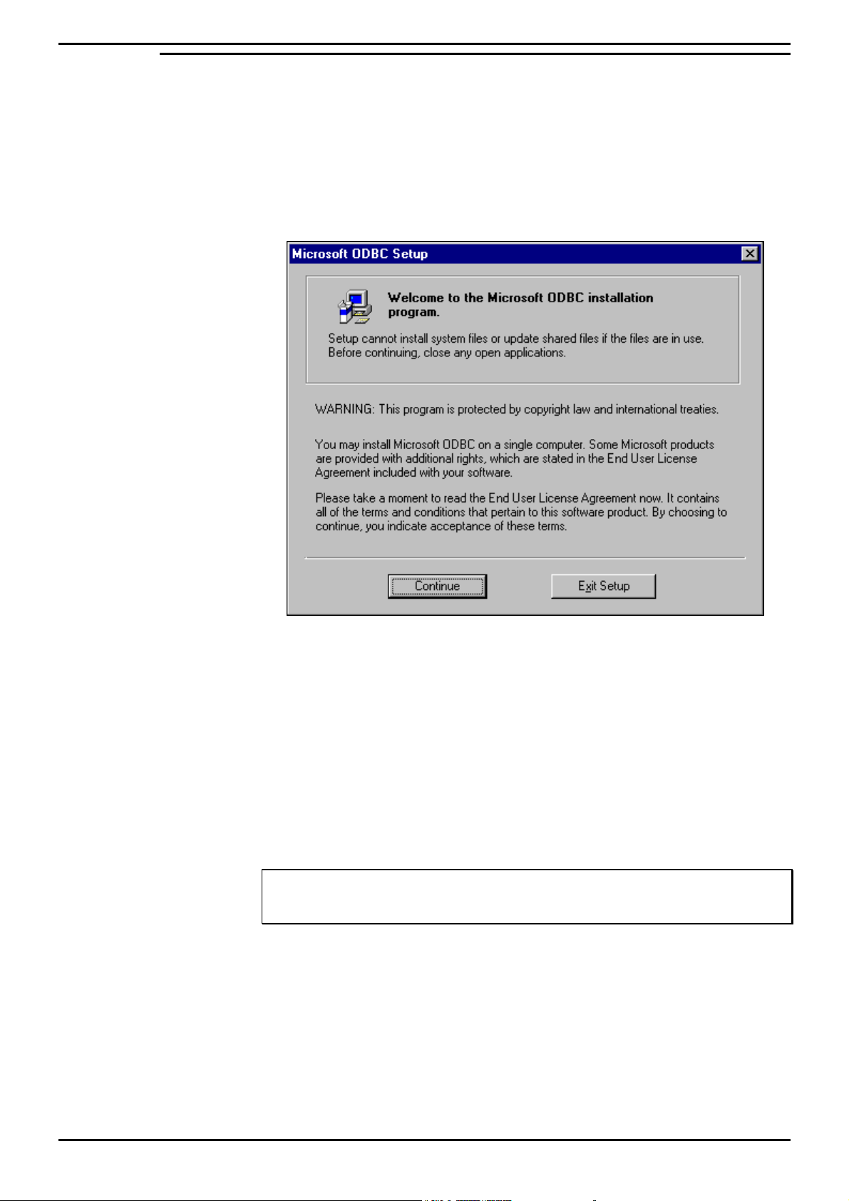
1. Insert the INDeX Application Service Pack CD in the CD Drive. From the
Windows taskbar, click Start and then select Run
2. In the Open text box type X:\NT Server\ODBC\Setup.exe. X is the letter
associated with the CD Drive of the PC. Click OK and then click Continue.
3. Click Continue to proceed. Enter name as Administrator and the name of your
Organisation, click OK.
4. Click Change to modify the information. Otherwise, click OK to confirm the
information to proceed.
5. Click Typical to continue with the installation.
6. Once the installation is complete, click OK.
IT IS HIGHLY RECOMMENDED TO RESTART THE PC.
You are now ready to install INDeX CCM applications.
Note
If the Server PC name has been changed you must perform the procedures detailed in
"Changing the ODBC Settings" on page 74.
1. Once the INDeX CCM applications have been installed, you need to expand the
database device as detailed in “the box next to SDXrepository. Whilst this is
highlighted ensure that the two boxes 'PUBLIC' and ’DB_OWNER' are checked
in the lower half of the window
2. Close the properties window, exit SQL Enterprise Manager.
Expand a Database” on page 88.
INDeX Contact Centre Modules Page 33
Installation & Maintenance 38HBK00001SCM - Issue 11 (05/01)
Page 34
PC Configuration Server PC – SPC20 (Max 20 Clients)
Windows NT Server Modifications
Regional Settings
The Regional Settings need to be changed from the default installation settings
which are usually English (United States).
1. From the Windows taskbar, click Start, point to Settings and select Control
Panel.
2. From the Control Panel, open Regional Settings.
3. From the Regional Settings tab select English (United Kingdom), click Apply,
and then click OK.
Note
Ensure the Regional Setting is appropriate for the relevant country.
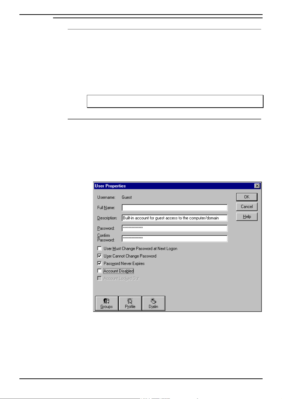
Guest Account
For INDeX CCM applications to communicate, the Guest Account on Windows NT
needs to be enabled. This is modified through the User Manager.
1. From the Windows taskbar, click Start, point to Programs and from
Administrative Tools (Common), select User Manager:
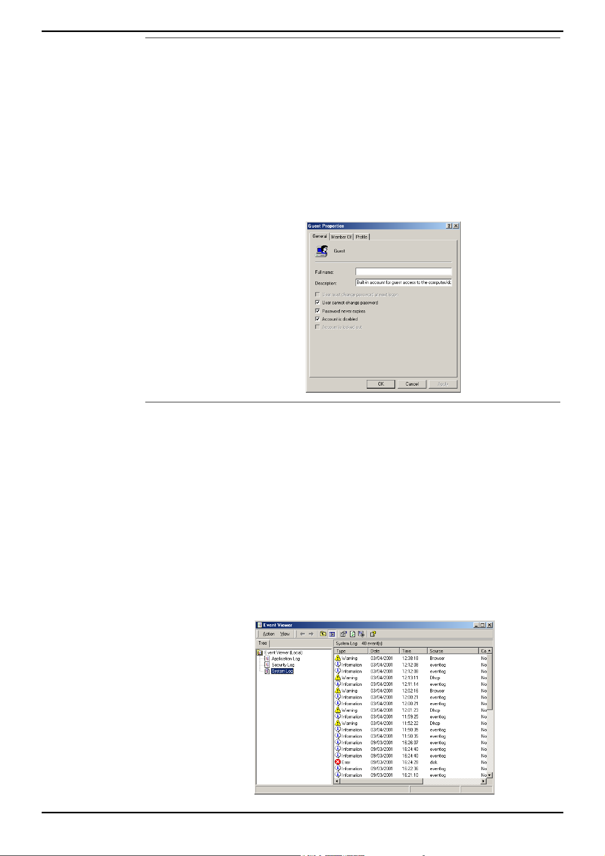
2. Double click Guest, ensure Account Disabled is unchecked as displayed in the
following screen. Click OK.
3. From the User menu, select Exit to close User Manager.
INDeX Contact Centre Modules Page 34
Installation & Maintenance 38HBK00001SCM - Issue 11 (05/01)
Page 35
PC Configuration Server PC – SPC20 (Max 20 Clients)
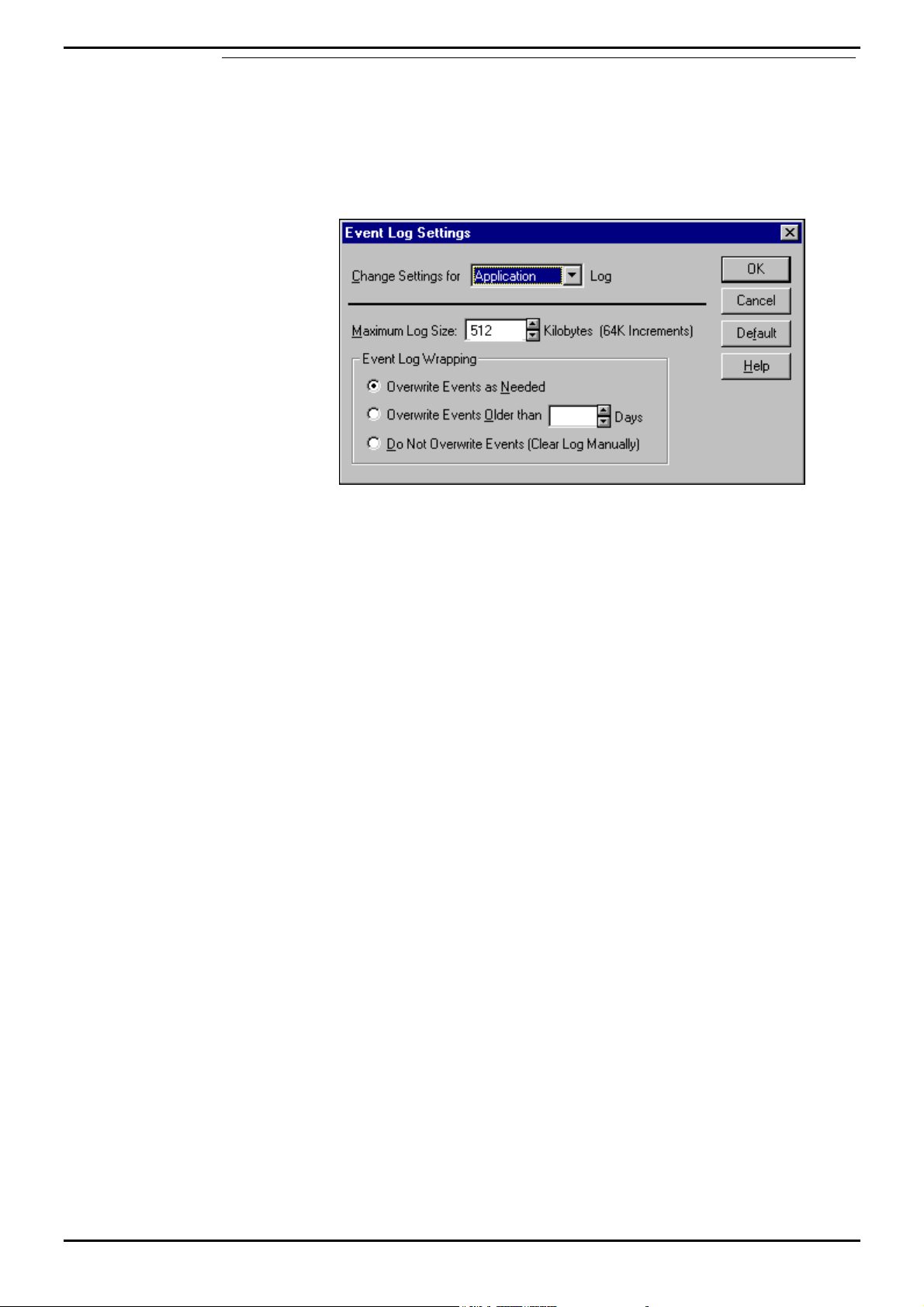
Event Log Settings
The Event Log settings are altered through the Windows NT Event Viewer.
1. From the Windows taskbar, click Start, point to Programs and from
Administrative Tools (Common), select Event Viewer.
2. From the Log menu, select Log Settings, the following screen appears:
3. There are three Settings available: System, Security and Application.
4. Use the pull down list select System and from the Event Log Wrapping options
ensure Overwrite Events as Needed is selected.
5. Repeat step 3 for the other two settings, i.e. Security and Application.
6. Click OK.
7. From the Log menu, select Exit to close the Event Viewer.
INDeX Contact Centre Modules Page 35
Installation & Maintenance 38HBK00001SCM - Issue 11 (05/01)
Page 36
PC Configuration Server PC – SPC20 (Max 20 Clients)
Sharing the Hard Drives
The following needs to be carried out on the Server PC running the INDeX CCM
Server applications.
In order for all INDeX CCM applications and the INDeX Taskbar to function
correctly, the drives on a Windows NT Server 4.0 PC must be shared.
1. From the Windows taskbar, click Start, point to Programs and select Windows
NT Explorer.
2. Click the C: drive using the right hand mouse button. From the context-sensitive
menu, select Sharing. You need to create a share named SDXSHARE and C if
one does not already exist.
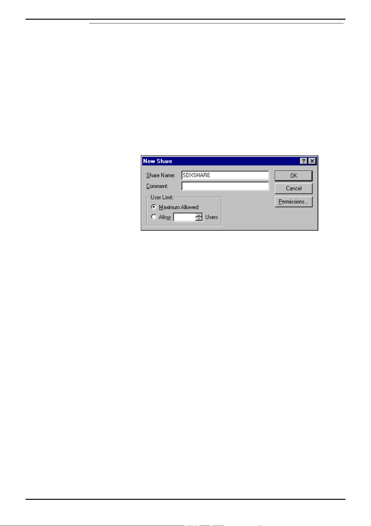
3. From the (C:\) Properties screen, click New Share. Type SDXSHARE (must be
UPPERCASE) as the Share Name as displayed in the following screen:
4. Ensure Maximum Allowed is also selected. Click OK.
5. Follow the above steps to create another share name called C.
6. From the (C:) Properties screen, click Apply and then click OK.
7. From the File menu, select Close to close the Windows NT Explorer.
Please refer to page 52 for information on how to Install INDeX CCM Applications.
INDeX Contact Centre Modules Page 36
Installation & Maintenance 38HBK00001SCM - Issue 11 (05/01)
Page 37
PC Configuration Server PC Setup – SPC5/10
Server PC Setup – SPC5/10
The same procedure is required when configuring INDeX CCM SPC5 and SPC10
Server PCs with the exception of the Disk Administrator (NTFS partition), as
detailed in this section.
1. Install Windows NT Server 4.0 as detailed on page 15
2. Install Windows NT Server Service Pack 6a as detailed on page 17
3 Create NTFS Partition using Disk Administrator as detailed on page 37
3. Install Display Adapter as detailed on page 22
4. Install EtherLink PCI Network Interface Card as detailed on page 23 and the
relevant Network setup as required
5. TCP/IP Networking Setup as detailed on page 25
6. Install ADR OnStream Tape Drive as detailed on page 27 (For SPC–10)
7. Install Advantech PCI Wallboard Comms Card as detailed on page 28
8. Install Microsoft SQL 7.0 as detailed on page 29
9. Install ODBC (Open Database Connectivity) as detailed on page 33
10. Windows NT Server Modifications as detailed on page 34
Create NTFS Partition using Disk Administrator
Disk Administrator is a graphical tool for managing disks. This tool encompasses
and extends the functionality of character-based disk management tools such as
MS-DOS FDISK.
1. From the Windows Taskbar, click Start, point to Programs, point to
Administrative Tools (Common) and click Disk Administrator. When running this
application for the first time, the following screen appears:
A scrollable, graphical representation of all the physical disks connected to your
computer along with their partition appears. A status bar at the bottom of the
window provides basic information on partitions. A colour-coded legend on top
of the status bar shows what the different partition colours and patterns
represent.
2. Click the D drive (i.e. CD-ROM).
3. From the Tools menu, click Assign Drive Letter. Click to select Assign Drive
Letter, and select letter E and then Click OK.
4. From the Confirmation screen, click Yes to continue.
INDeX Contact Centre Modules Page 37
Installation & Maintenance 38HBK00001SCM - Issue 11 (05/01)
Page 38

PC Configuration Server PC Setup – SPC5/10
5. If an NTFS partition does not exist on Disk 0, where the 1024MB partition is, you
need to create one by selecting the area of free space. From the Partition
menu, select Create. Click Yes to continue and create the partition.
The Create Primary Partition screen displays the size of the partition to be
created. This will usually be the maximum since it will contain all of the free
space available. Click OK.
6. From the Partition menu, select Commit Changes Now. Click Yes to save the
changes.
7. Click Yes to save the changes.
8. Click OK to update the emergency repair configuration and create a new
Emergency Repair Disk.
9. Click the D: drive, from the Tools menu, click Format. Set File System to
NTFS. Click Start to initiate the format request and then click OK to continue.
10. When the formatting is finished, click OK.
11. From the Format D:\ screen, click Close to return to the Disk Administrator
window.
12. From the Partition menu, click Exit to close the Disk Administrator application.
13. Reboot the PC.
INDeX Contact Centre Modules Page 38
Installation & Maintenance 38HBK00001SCM - Issue 11 (05/01)
Page 39

PC Configuration Client PC Setup (Windows NT – Workstation)
Client PC Setup (Windows NT – Workstation)
This section details the Client PC configuration as follows:
• Install Windows NT Workstation.
• Install Windows NT Service Pack 6a.
• Windows NT Workstation modifications for INDeX CCM applications.
• Map Network Drive
• Install Display Adapter.
• Install ODBC.
Install Windows NT 4.0 Workstation
1. Insert Windows NT CD-ROM and Windows NT Setup Disk 1 and reboot the PC.
2. When prompted, insert Windows NT Setup Disk 2 and press Enter.
3. Press Enter "To setup Windows NT now".
4. Press Enter to attempt to detect Mass Storage Devices in your PC.
5. When prompted, insert Windows NT Setup Disk 3 and press Enter to continue.
6. Press Enter to confirm that there is only one CD ROM storage device.
7. Press Page Down until you reach the end of the Licensing Agreement text and
then press F8 to agree.
8. With the Keyboard Layout: US highlighted, press Enter and then select United
Kingdom, to change the Keyboard Layout from US to United Kingdom.
9. With "The above list matches my computer" highlighted, press Enter.
10. With "Create partition of size (in MB): 1000" highlighted, press Enter.
11. Press Enter again to continue.
12. Select Format the Partition using FAT file system and press Enter to format the
partition.
13. With C:FAT, highlighted press Enter.
14. With "Leave the current file system intact", highlighted press Enter.
15. At \WINNT press Enter for this directory.
16. Press Enter to carry out an exhaustive search. Setup files will now be copied to
the PC.
17. When asked, remove the floppy disk (leaving the Windows NT CD in the CDROM Drive) and press Enter.
18. The PC restarts presenting a Windows NT Setup Wizard from which click Next.
19. From the "Setup Options" screen select Typical and click Next.
20. Type your Name as Administrator and your Organisation, click Next.
21. Enter the ID Number (from the Windows NT Workstation Manual), click Next.
22. Type Computer Name and click Next. You must ensure the PC name is NOT
called ARCHIVERSQL (e.g. Client_01).
23. Leave the Password fields blank and then click Next.
24. From the "Emergency Repair Disk" screen, select "No, do not create an
emergency repair disk" and click Next.
25. Select "Install the Most common Components (recommended)", click Next.
26. With 2) Installing Windows NT Networking selected, click Next.
27. Click to select “Do not connect this computer to a network at this time”, click
Next.
INDeX Contact Centre Modules Page 39
Installation & Maintenance 38HBK00001SCM - Issue 11 (05/01)
Page 40

PC Configuration Client PC Setup (Windows NT – Workstation)
Note
Installing the Network Interface Card is detailed in “Install EtherLink PCI Network
Interface Card” on page 23.
28. Click Finish to complete the setup.
29. From the Date/Time Properties screen, Set Time Zone to GMT and click Close.
30. From the Detected Display screen, click OK and then TEST to test the display.
31. Wait till colour screen closes, from the Testing Mode screen, click Yes and then
OK to save the display settings. From the Display Properties screen click OK.
32. Remove any floppy disks and CDs from the PC, click Restart Computer To
reboot the PC.
33. From the Begin Logon screen press Ctrl+Alt+Delete to log on.
34. From the Logon Information screen, enter the User name and Password, click
OK.
Install Service Pack 6a
Alteration to Windows NT 4.0's configuration including the addition of software mean
that the Service Pack (containing Microsoft bug fixes) need to be reapplied.
Perform the procedures detailed in “Install Windows NT Server Service Pack 6a” on
page 17.
Windows NT Workstation 4.0 Modifications
To be able to install and run the INDeX CCM application it is essential to modify
Windows NT as detailed in this section.
Perform the following procedures as detailed in:
• Regional Settings as detailed on page 34
• Guest Account as detailed on page 34
• Event Log Settings as detailed on page 35
• Install EtherLink PCI Network Interface Card as detailed on page 23 and the
relevant Network setup as required
INDeX Contact Centre Modules Page 40
Installation & Maintenance 38HBK00001SCM - Issue 11 (05/01)
Page 41
PC Configuration Client PC Setup (Windows NT – Workstation)
Map Network Drive
Sharing INDeX CCM
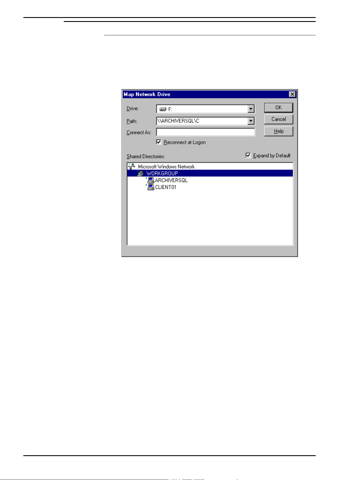
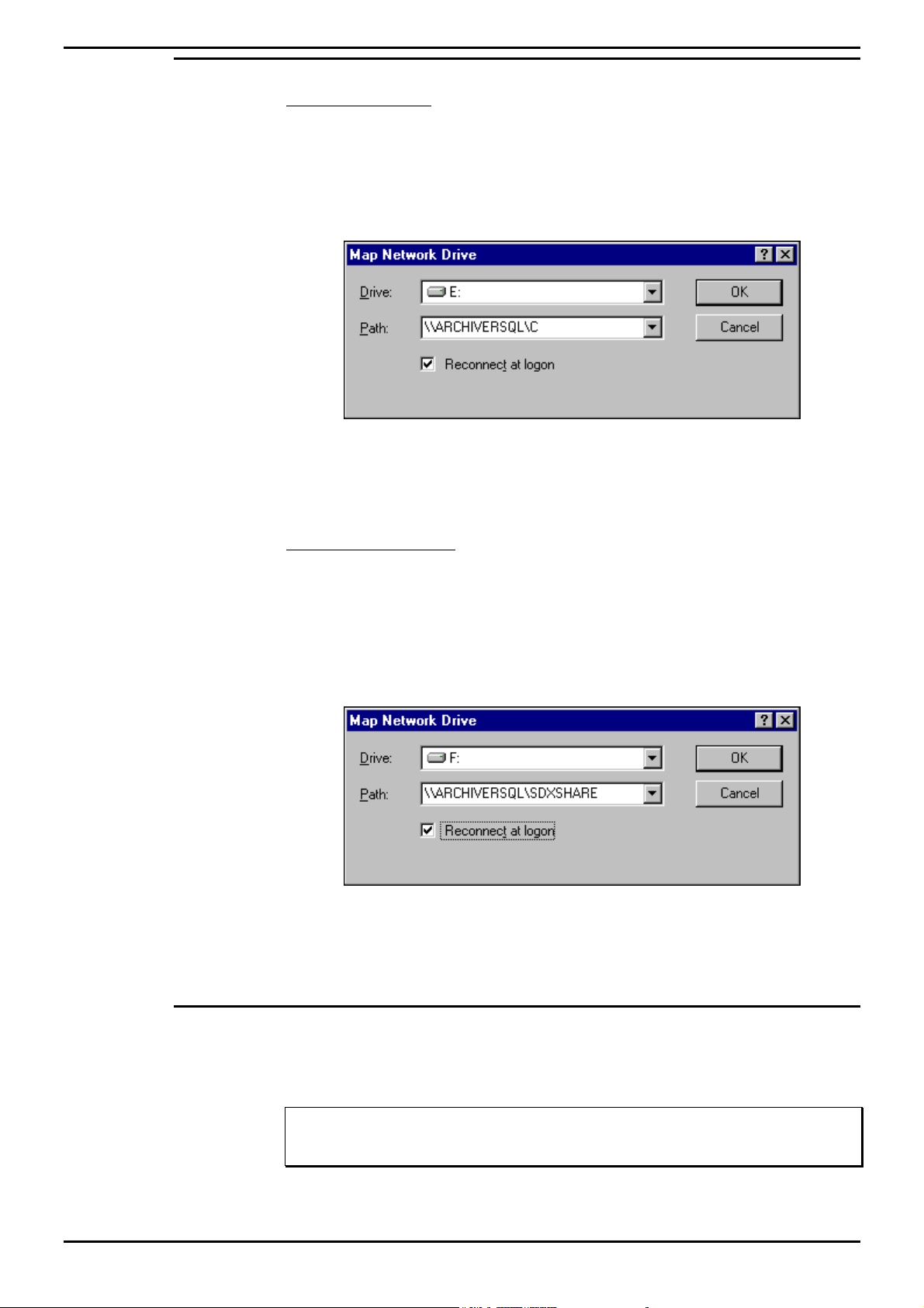
1. From the Windows NT desktop, click (using the right mouse button) Network
Neighborhood and select Map Network Drive.
2. Select a Map Drive (e.g. E:), in the Path Type \\ARCHIVERSQL\C, ensuring
Reconnect at logon is also checked as shown on the following screen:
3. Click OK.
This enables you to share the INDeX CCM (e.g. INDeX Call Centre View) files.
INDeX Contact Centre Modules Page 41
Installation & Maintenance 38HBK00001SCM - Issue 11 (05/01)
Page 42
PC Configuration Client PC Setup (Windows NT – Workstation)
Sharing INDeX Taskbar
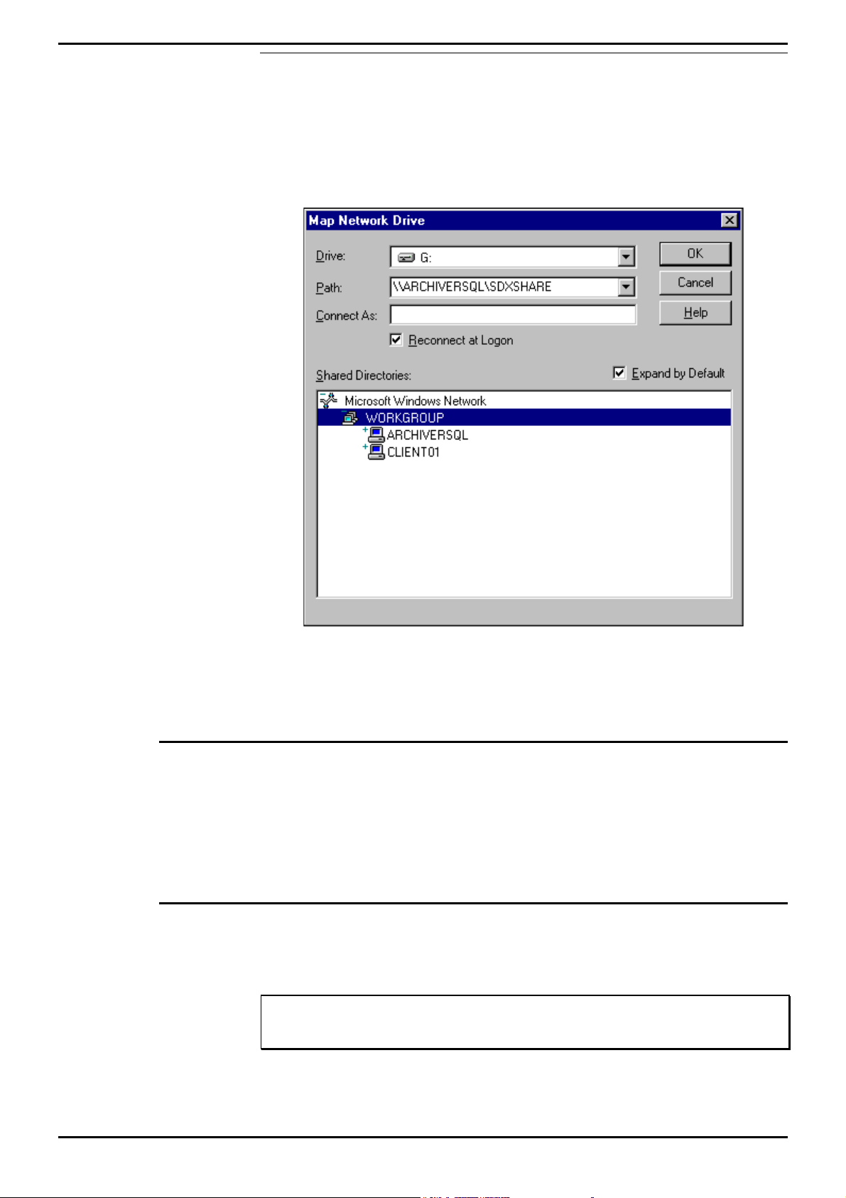
1. From the Windows NT desktop, click (using the right mouse button) Network
Neighborhood and select Map Network Drive.
2. Select a Map Drive (e.g. F:), in the Path Type \\ARCHIVERSQL\SDXSHARE,
ensuring Reconnect at logon is also checked as shown on the following
screen:
3. Click OK.
This enables you to share the INDeX Taskbar files.
Install Display Adapter
Since INDeX CCM applications are designed to use a screen resolution of 800 by
600 pixels, it is necessary to install a third party display adapter driver, which is not
installed by default when installing Windows NT.
To install Display Adapter see “Install Display Adapter” on page 22.
Install ODBC
ODBC provides a link between the database in the Server PC and the Client PC.
To install ODBC, see "Install ODBC (Open Database Connectivity)" on page 33.
Note
If the Server PC name has been changed you must perform the procedures detailed in
"Changing the ODBC Settings" on page 74.
You are now ready to install INDeX CCM applications.
INDeX Contact Centre Modules Page 42
Installation & Maintenance 38HBK00001SCM - Issue 11 (05/01)
Page 43

PC Configuration Client PC Setup (Window 98)
Client PC Setup (Window 98)
This section details the Client PC configuration as follows:
• Format the hard drive (if required).
• Install Windows 98.
• Install Display Adapter.
• Essential Windows 98 modification for INDeX CCM applications.
• Install EtherLink PCI network Interface Card.
• Map Network Drive.
• Install ODBC.
Format Hard Drive
1. With the PC switched off insert the Windows 98 Setup Disk in to the A:\ Drive.
Then switch the PC on.
2. At the X:\>Win98> (X is the letter associated with the CD ROM drive) prompt,
type cd\ and then press Enter. At the X:\> prompt type A:
3. At the A:\ prompt, type Format C: and press Enter. The following message will
be displayed:
"WARNING:
ALL DATA ON NON-REMOVABLE DISK DRIVE C: WILL BE LOST!
Proceed with format (Y/N?)"
4. Type Y and press Enter.
5. After formatting, press Enter to leave the volume label blank.
Install Windows 98
1. Insert Windows 98 CD-ROM and Windows 98 Setup Disk 1 and reboot the PC.
2. At the A:\ prompt, type X:, (X is the letter associated with the CD drive of the
PC) and press Enter.
3. At the X:\> prompt, type Setup and press Enter. Press Enter to continue.
Press X to exit Scan Disk. From the Windows 98 Setup Welcome screen, click
Continue to begin setup.
4. Select Directory C:\Windows, click Next. Select Typical, click Next.
5. Select Install the most common components (recommended), click Next.
6. Type Computer Name as required (i.e. Client_01), leaving the WORKGROUP
as it is. Click Next, select United Kingdom and then click Next.
7. At “Startup Disk” screen click Next to create a Startup Disk. Insert the Win98
Startup Disk and then click OK. When it has finished creating the Startup disk,
remove the disk from A:\ drive, and click OK.
8. Click Next to Start Copying Files. Type your name and Organisation, click Next.
9. Click to select “I accept the Agreement”, click Next. Type Product Key, click
Next and then click Finish.
10. From the Date/Time Properties screen, Set Time Zone to GMT London and click
Apply and then click OK.
11. Once the PC has restarted, enter the Network Password, click OK. Enter
Windows Password, click OK.
12. From Add New Hardware Wizard screen click Next and then follow the
instruction to install the Plug and Play Monitor, ensuring both Floppy Disk
drivers as well as CD-ROM drivers are selected.
13. Click Finish. Once the PC is restarted, close the Welcome to Windows 98
screen.
INDeX Contact Centre Modules Page 43
Installation & Maintenance 38HBK00001SCM - Issue 11 (05/01)
Page 44

PC Configuration Client PC Setup (Window 98)
Install Display Adapter
Since INDeX CCM applications are designed to use a screen resolution of 800 by
600 pixels, it is necessary to install a third party display adapter driver which is not
installed by default when installing Windows NT.
To install Display Adapter see “Install Display Adapter” on page 22.
Windows 98 Modifications
Once Windows 98 is installed, you need to make the following adjustments to be
able to run the INDeX CCM applications:
Regional Settings
When installing/running the INDeX CCM applications in the United Kingdom, the
Regional Settings needs to be changed from the default installation setting which is
usually set to English(United States).
1. From the Windows taskbar, click Start, point to Settings and select Control
Panel.
2. From the Control Panel options, open Regional Settings,
3. From the Regional Settings tab select English (United Kingdom), click Apply,
click Yes to restart the PC.
Note
Ensure the Regional Setting is appropriate for the relevant country.
INDeX Contact Centre Modules Page 44
Installation & Maintenance 38HBK00001SCM - Issue 11 (05/01)
Page 45

PC Configuration Client PC Setup (Window 98)
Install EtherLink PCI Network Interface Card
There are four steps to the NIC installation:
1. Run the pre-installation program before installing the NIC in the PC.
The EtherCD pre-installation program prevents conflicts with the NIC and your
operating system. It guides you through the NIC installation and must be run
before you physically install the NIC in the PC.
2. Install the NIC in the PC.
3. Connect the NIC to the network.
4. Install the network driver.
Note
If there is network card in the PC, you must remove the Adapter and the Network card
from the PC.
1. Run the Pre-installation Program
Before you physically install the NIC in a PC, run the NIC pre-installation program to
properly set up your system environment.
The pre-installation program prevents conflicts with the NIC and your operating
system. It guides you through the NIC installation and must be run before you
physically install the NIC in the PC.
To run the NIC pre-installation program:
1. Do NOT install the NIC in the PC.
2. Turn on the power to the PC and start Windows.
3. Quit any open applications and disable the automatic protection feature of any
anti-virus software that may be running.
4. Insert the EtherCD in the CD-ROM drive.
The EtherCD Welcome screen appears. If the EtherCD Welcome screen does
not appear, enter the following command from the Run option of the Windows
Start menu: X:\installs\setup.exe where X:\ represents the letter of the CD-ROM
drive.
5. Click NIC Software.
6. Click NIC Drivers and Diagnostics.
7. Click Install NIC Driver.
To install the network driver and the 3Com NIC Diagnostics program, click
Install with Diagnostic Program. (We recommend you select this option).
To install the network driver only, click Install without Diagnostic Program.
Files are copied. A message box appears when the installation is complete.
8. Click OK.
9. Select your operating system (Windows 98) to continue the installation.
The Completing NIC Installation screen appears.
10. Click Done.
11. Exit the EtherCD, and then shut down Windows.
12. Turn off the power to the PC.
INDeX Contact Centre Modules Page 45
Installation & Maintenance 38HBK00001SCM - Issue 11 (05/01)
Page 46

PC Configuration Client PC Setup (Window 98)
2. Install the NIC in the PC
To install the NIC in the PC:
1. Make sure that you have run the preinstallation program, as described in the
previous section.
2. Turn off the power to the PC and unplug the power cord.
3. Remove the cover from the PC.
4. Locate an empty, nonshared bus-mastering PCI slot and remove its slot cover.
Save the screw.
Do not install the NIC in a shared PCI slot. Avoid any PCI slot next to an ISA
slot. This is often a shared slot and does not support bus mastering.
5. Carefully insert the NIC in the empty PCI slot. Press firmly to ensure that the
NIC is fully seated in the slot.
6. Secure the NIC with the screw you removed earlier.
7. Replace the PC cover and plug in the power cord.
Do NOT turn on the power to the PC.
3. Connect the NIC to the Network
Connect the appropriate network cable to the NIC provided by the Network
Administrator of the Customer’s Site.
4. Install the Network Driver
To install the network driver:
1. Turn on the power to the PC. Windows 98 detects the NIC.
2. The Add New Hardware Wizard starts, click to select “Display a list of all the
drivers in a specific location” and then click Next.
3. With the Network Adapter selected, click OK.
4. When prompted insert the EtherCD in the CD ROM drive and then click OK.
5. From Insert Disk screen, type the CD ROM drive letter, (e.g. d:\).
6. Click OK and then click Finish.
7. You must restart the PC to complete the installation.
You are now ready to adjust the Networking Setup according to the Customer’s
Network, i.e. either TCPIP or IPX/SPX as detailed in following pages.
TCP/IP Networking setup
This is only applicable if the site network uses TCP/IP. Otherwise, configure the
network according to the Site's Network.
1. From the Windows taskbar, click Start, point to Settings and select Control
Panel.
2. From the Control Panel options open, Network.
3. Highlight TCP/IP Protocol and click Properties. Add the settings specified by
the customer's Network Manager and then click OK.
4. Click OK and allow the Client PC to restart.
INDeX Contact Centre Modules Page 46
Installation & Maintenance 38HBK00001SCM - Issue 11 (05/01)
Page 47
PC Configuration Client PC Setup (Window 98)
Network IPX Frame Type
This is only applicable if the site network uses IPX Frame Type. Otherwise,
configure the network according to the Site's Network.
1. From the Windows taskbar, click Start, point to Settings and select Control
Panel.
2. From the Control Panel options open, Network.
3. Click IPX/SPX compatible Protocol, click Properties.
4. Click to select, "I want to enable NetBOIS over IPX/SPX” and then click OK.
5. From the IPX/SPX compatible Protocol Properties screen, click the
Advanced tab, and highlight the ‘Frame Type’ Property, then from the Value
drop-down list, select Ethernet II.
6. Click OK.
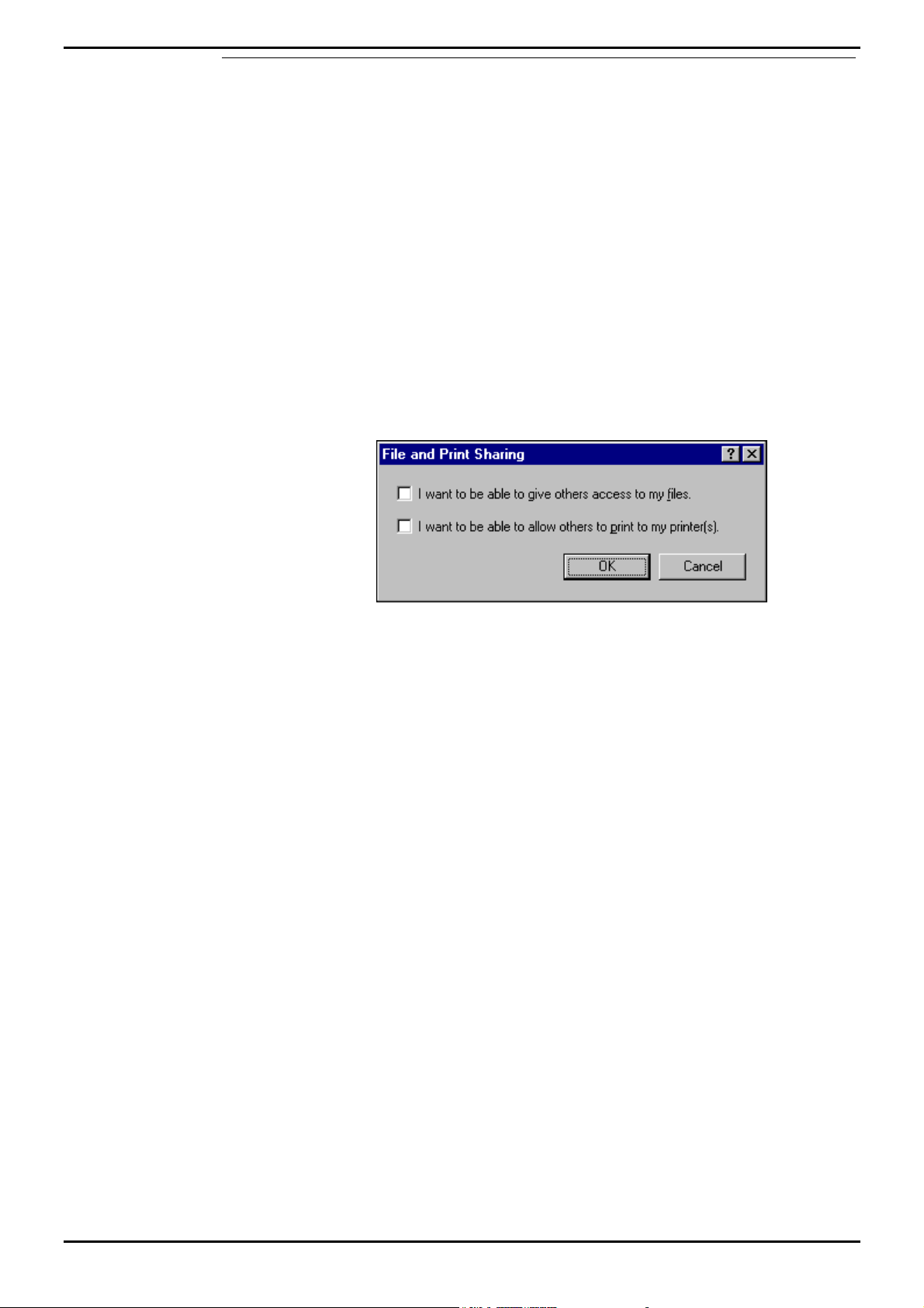
7. From the Network screen, click File and Print Sharing the following screen
appears:
8. Click to select both options and click OK.
9. From the Network screen, click the Identification tab, enter the Computer
name and Workgroup as required.
10. Click OK.
11. When prompted, click Yes to restart the PC.
INDeX Contact Centre Modules Page 47
Installation & Maintenance 38HBK00001SCM - Issue 11 (05/01)
Page 48
PC Configuration Client PC Setup (Window 98)
Map Network Drive
Sharing INDeX CCM
1. From the Windows 98 desktop, click (using the right mouse button) Network
Neighborhood and select Map Network Drive.
2. Select a Map Drive (e.g. E:), in the Path Type \\ARCHIVERSQL\C, ensuring
Reconnect at logon is also checked as shown on the following screen:
3. Click OK.
This enables you to share the INDeX CCM (e.g. INDeX Call Centre View) files.
Sharing INDeX Taskbar
1. From the Windows 98 desktop, click (using the right mouse button) Network
Neighborhood and select Map Network Drive.
2. Select a Map Drive (e.g. F:), in the Path Type \\ARCHIVERSQL\SDXSHARE,
ensuring Reconnect at logon is also checked as shown on the following
screen:
3. Click OK.
This enables you to share the INDeX Taskbar files.
Install ODBC
ODBC provides a link between the database in the Server PC and the Client PC.
To install ODBC see "Install ODBC (Open Database Connectivity)" on page 33.
Note
If the Server PC name has been changed you must perform the procedures detailed in
"Changing the ODBC Settings" on page 74.
You are now ready to install INDeX CCM applications.
INDeX Contact Centre Modules Page 48
Installation & Maintenance 38HBK00001SCM - Issue 11 (05/01)
Page 49

PC Configuration Client PC Setup (Windows 2000)
Client PC Setup (Windows 2000)
This section details the Client PC configuration as follows:
• Install Windows 2000 Service Pack 1.
• Windows 2000 modifications for INDeX CCM applications.
• Map Network Drive
• Install Display Adapter.
• Install ODBC.
Install Service Pack 1
Alteration to Windows 2000's configuration including the addition of software mean
that the Service Pack (containing Microsoft bug fixes) needs to be reapplied.
Follow the instructions on your Windows 2000 disk to re-install the service pack.
Windows 2000 Modifications
To be able to install and run the INDeX CCM application it is essential to modify
Windows 2000 as detailed in this section.
Perform the following procedures as detailed in:
• Regional Settings as detailed below
• Guest Account as detailed on page 50
• Event Log Settings as detailed on page 50
• Install EtherLink PCI Network Interface Card as detailed on page 23 and the
relevant Network setup as required
Regional Settings
The Regional Settings need to be changed from the default installation settings
which are usually English (United States).
1. From the Windows Taskbar, click Start, point to Settings and select Control
Panel.
2. From the Control Panel, open Regional Options.
3. From the General Tab select English (United Kingdom), click Apply and then
click on Ok.
INDeX Contact Centre Modules Page 49
Installation & Maintenance 38HBK00001SCM - Issue 11 (05/01)
Page 50
PC Configuration Client PC Setup (Windows 2000)
Guest Accounts
For INDeX CCM applications to communicate, the Guest Account on Windows 2000
needs to be enabled. To modify the Guest Account:
1. From the Windows Taskbar, click Start, point to settings and select Control
Panel.
2. From the Control panel, open Users and Passwords
3. Click on the Advanced Tab. In the Advanced User Management section click
on the Advanced button.
4. Open the Users folder and then double click on Guest.
5. Click on the General Tab. Remove the tick by 'Account is disabled' then click on
the Apply button. Click on Ok and then close all screens.
Event Log Settings
The Event Log settings are altered through the windows Event Viewer. To do this:
1. From the Windows Taskbar, Click Start, point to settings and select Control
Panel.
2. From the Control panel open Administrative Tools
3. Open Event Viewer.
4. Right Mouse click on Application Log and select properties. In the Log size
section select overwrite events as needed. Click on apply and then Ok.
5. Right mouse click on Security Log and select properties. In the Log size section
select overwrite events as needed. Click on apply and then Ok.
6. Right mouse click on System Log and select properties. In the Log size section
select overwrite events as needed. Click on apply and then Ok.
7. Close all open windows.
INDeX Contact Centre Modules Page 50
Installation & Maintenance 38HBK00001SCM - Issue 11 (05/01)
Page 51

PC Configuration Client PC Setup (Windows 2000)
Map Network Drive
Sharing INDeX CCM
1. From the Windows desktop, click (using the right mouse button) my Network
Places and select Map Network Drive.
2. Select a Map Drive (e.g. E:).
3. In the Folder section type \\ARCHIVERSQL\C
4. Make sure that the Reconnect at logon is also checked as shown on the
screen shown below.
5. Click on Finish.
This enables you to share the INDeX CCM (e.g. INDeX Call Centre View) files.
Sharing INDeX Taskbar
1. From the Windows desktop, click (using the right mouse button) My Network
Places and select Map Network Drive.
2. Select a Map Drive (e.g. F:).
3. In the Path Type \\ARCHIVERSQL\SDXSHARE, ensuring Reconnect at logon
is also checked.
4. Click on Finish.
Install Display Adapter
Since INDeX CCM applications are designed to use a screen resolution of 800 by
600 pixels, it is necessary to install a third party display adapter driver, which is not
installed by default when installing Windows.
To install Display Adapter see “Install Display Adapter” on page 22.
Install ODBC
ODBC provides a link between the database in the Server PC and the Client PC.
To install ODBC, see "Install ODBC (Open Database Connectivity)" on page 33.
Note
If the Server PC name has been changed you must perform the procedures detailed in
"Changing the ODBC Settings" on page 74.
You are now ready to install INDeX CCM applications.
INDeX Contact Centre Modules Page 51
Installation & Maintenance 38HBK00001SCM - Issue 11 (05/01)
Page 52

Install INDeX CCM Applications Overview
Install INDeX CCM Applications
Overview
This section describes the procedures of installing the software for the INDeX
Contact Centre suite. The installation procedure is divided into the following steps,
which must be performed:
1. Install INDeX CCM applications.
2. Setting SQL Server Configuration Information.
3. Install Windows NT Service Pack 6a.
Note
Once you have completed the installation of the INDeX CCM, ensure you REINSTALL
Windows NT Service Pack 6a, as detailed “Install Windows NT Server Service Pack 6a” on
page 17
Integration of INDeX CCM with INDeX Voice Manager
To integrate INDeX CCM with INDeX Voice Manager, there must only be one
Access Manager running within the system. In this case, the Access Manager must
reside on the Server Cassette.
For the installation of the INDeX Voice Manager, refer to the "INDeX Voice Manager
Installation and Maintenance Manual".
Since the Access Manager resides within the Server Cassette, to integrate INDeX
CCM with INDeX Voice Manager, you need to Disable the INDeX Access Manager
Service residing in the INDeX CCM Server PC.
1. After the INDeX CCM Server PC is restarted, from the Windows NT taskbar,
click Start, point to Settings and select Control Panel.
2. From the Control Panel options open, Services.
3. Select the INDeX Access Manager and then click Stop.
4. Click Yes to agree to stop the service.
5. With the INDeX Access Manager selected, click Startup.
6. From Service screen, click to select Disable as the Startup Type and then click
OK.
7. From Services screen, click Close and then exit Control Panel.
Note
To enable the INDeX Access Manager Service, set the Startup Type to Automatic and then
restart the PC.
INDeX Contact Centre Modules Page 52
Installation & Maintenance 38HBK00001SCM - Issue 11 (05/01)
Page 53

Install INDeX CCM Applications INDeX CCM on Standalone Server PC
INDeX CCM on Standalone Server PC
The required INDeX CCM applications are:
1. INDeX Access Manager
2. INDeX Delta Server
3. INDeX Wallboard Server
4. INDeX Report Manager
5. INDeX Taskbar
6. INDeX Network Administrator
7. INDeX Call Centre View
If integrating INDeX CCM with INDeX Voice Manager, follow the procedures
detailed in "Integration of INDeX CCM with INDeX Voice Manager" on page 52,
when installing the Access Manager.
When installing more than one Server Components there is a 2-minute time delay
between each Server application.
After having installed all the Server and Client Components:
1. from the INDeX Install Wizard, click Finish to end the INDeX Install Wizard.
Restart the PC.
2. ensure that all the files copied to Windows NT are up to the Service Pack 6a
level, by installing Service Pack 6a AGAIN as detailed in “Install Windows NT
Server Service Pack 6a” on page 17.
IT IS HIGHLY RECOMMENDED TO RESTART THE PC ONCE THE
INSTALLATION OF THE INDEX CCM APPLICATIONS IS COMPLETE.
Note 1:
After starting up the Server PC, it is necessary to Logon to it. This should be done no sooner
than 10 seconds after the Logon prompt is displayed.
Note 2:
After Logging onto a newly started Server PC, INDeX Taskbar, INDeX Access Manager, INDeX
Delta Server, Document Agent Server and INDeX Archiver will all start automatically. These
are all timed starts and this will take 1-2 minutes.
INDeX Contact Centre Modules Page 53
Installation & Maintenance 38HBK00001SCM - Issue 11 (05/01)
Page 54

Install INDeX CCM Applications INDeX CCM on Server PC/Client PC
INDeX CCM on Server PC/Client PC
For a Server PC/Client PC scenario the required INDeX CCM applications are:
Server PC:
1. INDeX Access Manager
2. INDeX Delta Server
3. INDeX Taskbar
4. INDeX Network Administrator
5. INDeX Report Manager
6. INDeX Wallboard Server
Client PC:
1. INDeX Taskbar
2. INDeX Report Client
3. INDeX Wallboard Client
4. INDeX Call Centre View
5. INDeX Network Administrator
If integrating INDeX CCM with INDeX Voice Manager, follow the procedures
detailed in "Integration of INDeX CCM with INDeX Voice Manager" on page 52,
when installing the Access Manager.
After having installed all the Server and Client Components:
1. from the INDeX Install Wizard, click Finish to end the INDeX Install Wizard.
Restart the PC.
2. ensure that all the files copied to Windows NT are up to the Service Pack 6a
level, by installing Service Pack 6a AGAIN as detailed in “Install Windows NT
Server Service Pack 6a” on page 17.
When installing more than one Server Components there is a 2-minute time delay
between each Server application.
IT IS HIGHLY RECOMMENDED TO RESTART THE PCs ONCE THE
INSTALLATION OF THE INDEX CCM APPLICATIONS IS COMPLETE.
Note 1:
After starting up the Server PC, it is necessary to Logon to it. This should be done no sooner
than 10 seconds after the Logon prompt is displayed.
Note 2:
After Logging onto a newly started Server PC, INDeX Taskbar, INDeX Access Manager, INDeX
Delta Server, Document Agent Server and INDeX Archiver will all start automatically. These
are all timed starts and this will take 1-2 minutes.
INDeX Contact Centre Modules Page 54
Installation & Maintenance 38HBK00001SCM - Issue 11 (05/01)
Page 55

Install INDeX CCM Applications INDeX CCM Server Applications
INDeX CCM Server Applications
1. With the Windows NT running, insert the INDeX Application CD in the CD
Drive. The auto run sequence executes the Installation.
Note
INDeX CCM application's PC, requires a MINIMUM of 128MB of RAM for the Server PCs
and 64MB of RAM for the Client PCs.
2. Click Next the following screen appears:
INDeX Contact Centre Modules Page 55
Installation & Maintenance 38HBK00001SCM - Issue 11 (05/01)
Page 56
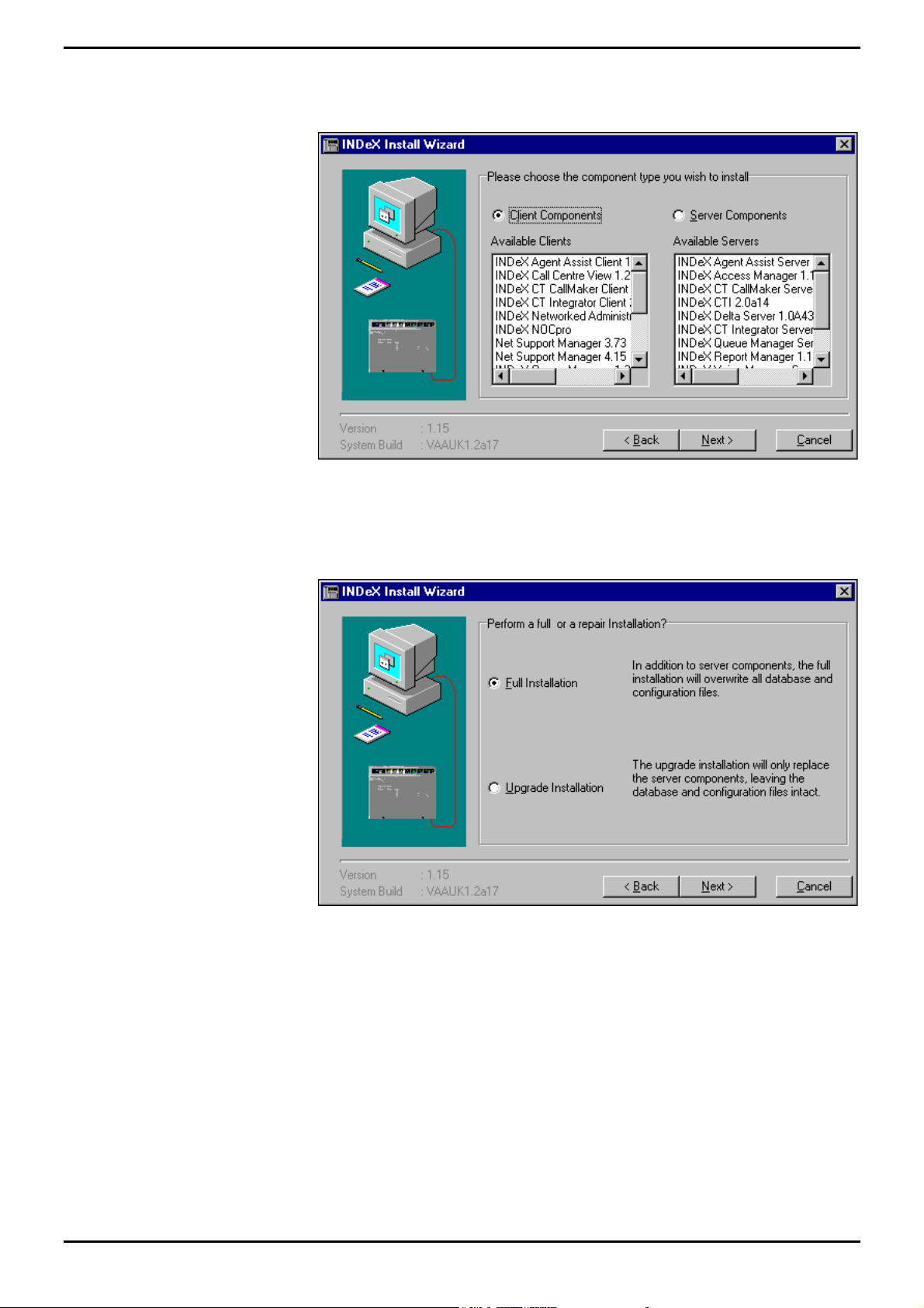
Install INDeX CCM Applications INDeX CCM Server Applications
3. Enter the CD-ROM Drive (e.g. e:\) and then click Next the following screen
appears, listing the Client and Server Components available for installation:
4. Check that the Available Servers list includes the required Server applications.
5. Select Server Components and click Next, the following screen appears:
INDeX Contact Centre Modules Page 56
Installation & Maintenance 38HBK00001SCM - Issue 11 (05/01)
Page 57

Install INDeX CCM Applications INDeX CCM Server Applications
6. Select Full Installation and click Next, the following screen appears:
7. Click Next to proceed to the following screen.
This screen displays the list of available INDeX Server Components as well as the
status of the existing server components on the Server PC.
Note
Picking one component may automatically select other components normally installed with
it. You can manually de-select those other components if not required. For example,
selecting INDeX Wallboard Server, you will notice that the INDeX Access Manager and INDeX
Delta Server are automatically checked.
System Status:
Not on System – The Server Component is not installed;
System is Current – The same version of the Server Component is already
installed;
System is Older – The Server Component is already installed and is a later version
of the one available for installation;
System Incompatible – The Server Component available for installation is not
compatible with other components already installed.
INDeX Contact Centre Modules Page 57
Installation & Maintenance 38HBK00001SCM - Issue 11 (05/01)
Page 58
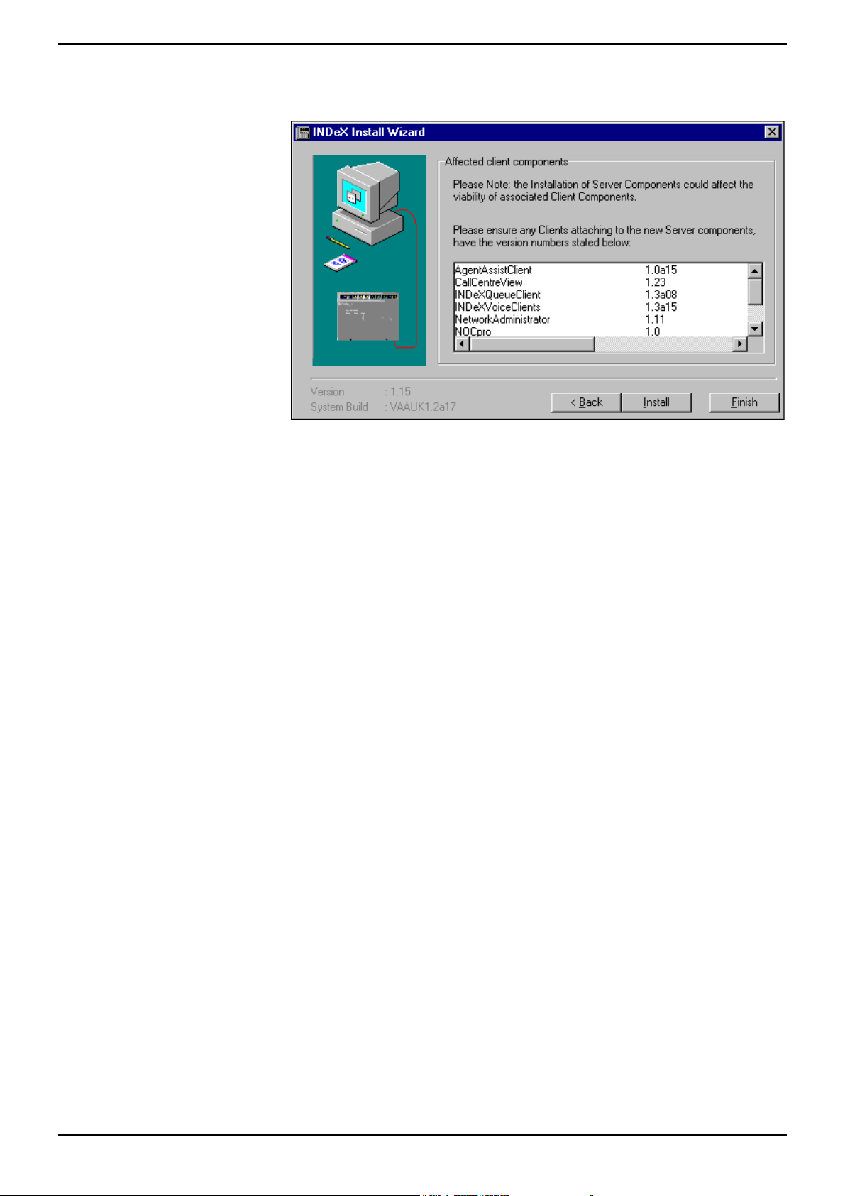
Install INDeX CCM Applications INDeX CCM Server Applications
8. Select the required Server Component(s) and then click Next to proceed to the
following screen:
9. The list of Client applications depends upon the Server applications that are
selected to be installed. Click Install. See the relevant sections for each
product installation.
Once all the Server Components have been installed, follow the instructions
detailed in "INDeX CCM Client Applications" on page 59 to install the Client
components.
INDeX Contact Centre Modules Page 58
Installation & Maintenance 38HBK00001SCM - Issue 11 (05/01)
Page 59

Install INDeX CCM Applications INDeX CCM Server Applications
INDeX CCM Client Applications
If you have just completed installing INDeX CCM Server applications, the following
screen appears:
The list of Client applications depends upon the Server applications that are
selected to be installed.
Click Back till you reach the screen in step 3 (below) and follow the instructions from
step 4 on wards.
Otherwise:
1. Insert the INDeX Application CD in the CD Drive. The auto run sequence
executes the Installation Wizard.
Note
INDeX CCM application's PC, requires a MINIMUM of 64MB of RAM.
2. Click Next the following screen appears:
INDeX Contact Centre Modules Page 59
Installation & Maintenance 38HBK00001SCM - Issue 11 (05/01)
Page 60
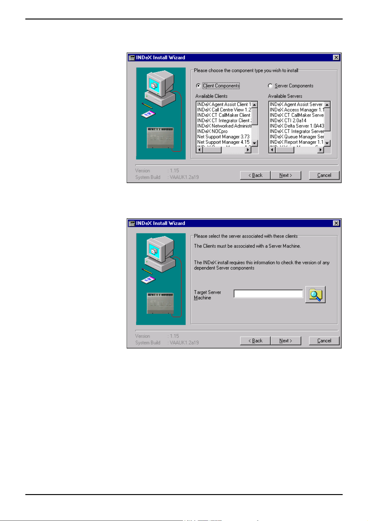
Install INDeX CCM Applications INDeX CCM Server Applications
3. Enter the CD-ROM Drive (e.g. e:\) and then click Next the following screen
appears, listing the Client and Server Components available for installation:
4. Click Next to proceed to the following screen:
5. Click Search button, Browse for Computer screen .
6. Select the Target Server Machine (e.g. Archiversql), click OK.
INDeX Contact Centre Modules Page 60
Installation & Maintenance 38HBK00001SCM - Issue 11 (05/01)
Page 61
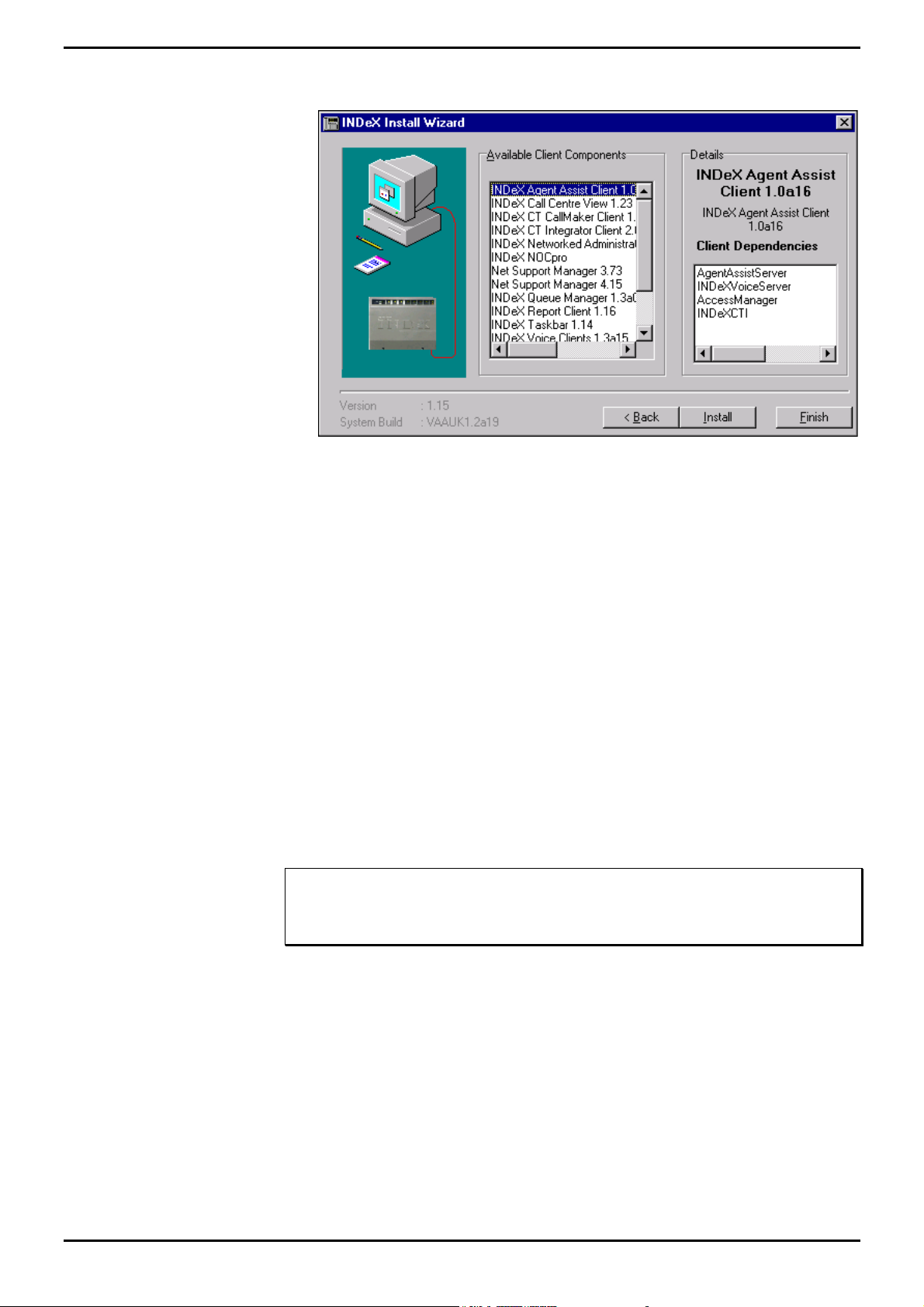
Install INDeX CCM Applications INDeX CCM Server Applications
7. Click Next to the following screen:
This screen shows the list of Available Client Components plus a list of Client
Dependencies for whichever Client Component is currently highlighted. The
presence and version numbers of those Client Dependencies will be checked when
you install any of the Client Components.
Each of the Client Dependencies for the Client Component is checked.
– If it is compatible, no message appears.
– If a Client Dependency is not present or an incompatible version, then a
warning message will be displayed. Take a note of the message before
canceling installation by clicking on Finish. You will have to install the
missing dependency before installing the Client Components.
8. Select the required Client application and then click Install Client. See the
relevant sections for each product installation.
When all the INDeX CCM Client applications have been installed, click Finish to
close the INDeX Install Wizard and restart the PC..
Note
When installing INDeX CCM Client applications on Windows NT Workstation/Server, ensure to
reinstall Service Pack 6a as detailed in “Install Windows NT Server Service Pack 6a” on page
17.
INDeX Contact Centre Modules Page 61
Installation & Maintenance 38HBK00001SCM - Issue 11 (05/01)
Page 62
Install INDeX CCM Applications INDeX CCM Server Applications
INDeX Wallboard Server
1. Once you clicked Install Servers, the Welcome screen appears.
2. Click Next a Restart message screen appears.
3. Click OK to complete the INDeX Wallboard Server installation.
4. Click Finish.
When installing more than one Server Component there is a 2-minute time delay
between each Server application.
INDeX Delta Server
With the installation of the INDeX Wallboard Server complete, the Delta Server
Welcome screen appears to indicate the start of the INDeX Delta Server installation
program:
1. From the Welcome screen, click Next to commence the installation, the
following screen appears:
.
2. If you do not wish to view the Agent details in any of the INDeX CCM
applications (i.e. Call Centre View, Wallboard Server, Report Client) you must
click No.
3. If you wish to view the Agent details in any of the INDeX CCM applications (i.e.
Call Centre View) you must click Yes.
Note
This feature has been introduced for the German Market.
4. When the Installation Completed screen appears, click Finish to complete the
INDeX Delta Server installation.
When installing more than one Server Component there is a 2-minute time delay
between each Server application.
INDeX Contact Centre Modules Page 62
Installation & Maintenance 38HBK00001SCM - Issue 11 (05/01)
Page 63

Install INDeX CCM Applications INDeX CCM Server Applications
INDeX Access Manager
With the installation of the INDeX Delta Server complete, the INDeX Access
Manager Welcome screen appears to indicate the start of the installation program.
1. From the Welcome screen, click Next to commence the installation.
Note
If integrating INDeX CCM with INDeX Voice Manager, follow the procedures detailed in
"Integration of INDeX CCM with INDeX Voice Manager" on page 52, when installing the
Access Manager.
When installing more than one Server Component there is a 2-minute time delay
between each Server application.
INDeX Contact Centre Modules Page 63
Installation & Maintenance 38HBK00001SCM - Issue 11 (05/01)
Page 64

Install INDeX CCM Applications INDeX CCM Server Applications
INDeX Report Manager
With the installation of the INDeX Access Manager complete, the following screen
appears to indicate the start of the INDeX Report Manager installation program.
1. From the Welcome screen, click Next to commence the installation. During the
installation the following screen appears:
3. When installing this application for the first time, you MUST click Yes to
configure the INDeX Archiver to 2000MB. (This takes about 20 minutes).
4. When upgrading this application, follow the Release Notes associated with
Upgrading the INDeX Report Manager application. However if you click Yes,
the following appears:
5. Click No, the database device will not be replaced and go to step 10.
Alternatively,
6. Click Yes the following screen appears:
7. Click Yes to overwrite the existing Reports Database.
Alternatively;
8. Click No.
9. Once the INDeX Archiver database configuration is complete the following
screen appears:
10. Click OK.
11. Form the Installation Complete screen, click Finish.
When installing more than one Server Component there is a 2-minute time delay
between each Server application.
INDeX Contact Centre Modules Page 64
Installation & Maintenance 38HBK00001SCM - Issue 11 (05/01)
Page 65

Install INDeX CCM Applications INDeX CCM Server Applications
INDeX Taskbar
1. From the INDeX Install Wizard screen, select INDeX Taskbar:
2. Click Install.
3. Select the required Setup language and then click OK.
4. From the Welcome screen, click Next to continue.
5. From Select Program Folder click Next to continue.
6. At the Microsoft comctl32.dll Update warning message, click OK to continue.
7. Click OK to proceed to the following screen:
8. Click Finish to complete the installation program.
INDeX Networked Administration
1. From the INDeX Install Wizard screen, select INDeX Networked Administration.
2. Click Install.
3. Select the required Setup language and then click OK to continue.
4. Click Next to continue.
5. To install to a different directory, click Browse, and select another directory.
6. To install to the directory on the screen, click Next the following screen appears:
7. Click Finish to complete the installation.
INDeX Contact Centre Modules Page 65
Installation & Maintenance 38HBK00001SCM - Issue 11 (05/01)
Page 66

Install INDeX CCM Applications INDeX CCM Server Applications
INDeX Call Centre View
1. From the INDeX Install Wizard screen, select INDeX Call Centre View:
2. Click Install.
3. From the Welcome screen, click Next the following screen appears:
4. Middleware component checks the version number of the relevant Server
applications required when running the Client application.
5. Type the name of the PC where the Server application resides or click Search
and select from the list. Type Administrator as the User name and type the
Password if one specified. Click OK to continue. You will need to enter the
information twice depending upon the Server dependencies.
6. When installing this application on Window95/98 the following screen appears:
INDeX Contact Centre Modules Page 66
Installation & Maintenance 38HBK00001SCM - Issue 11 (05/01)
Page 67
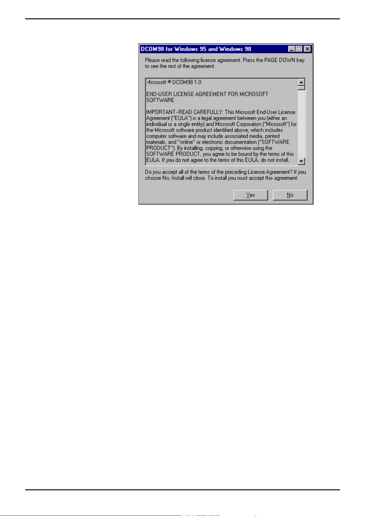
Install INDeX CCM Applications INDeX CCM Server Applications
7. Click Yes to proceed to the following screen:
8. Click Yes to accept the License Agreement.
9. From the Installation Complete, click Finish to complete the installation.
INDeX Contact Centre Modules Page 67
Installation & Maintenance 38HBK00001SCM - Issue 11 (05/01)
Page 68
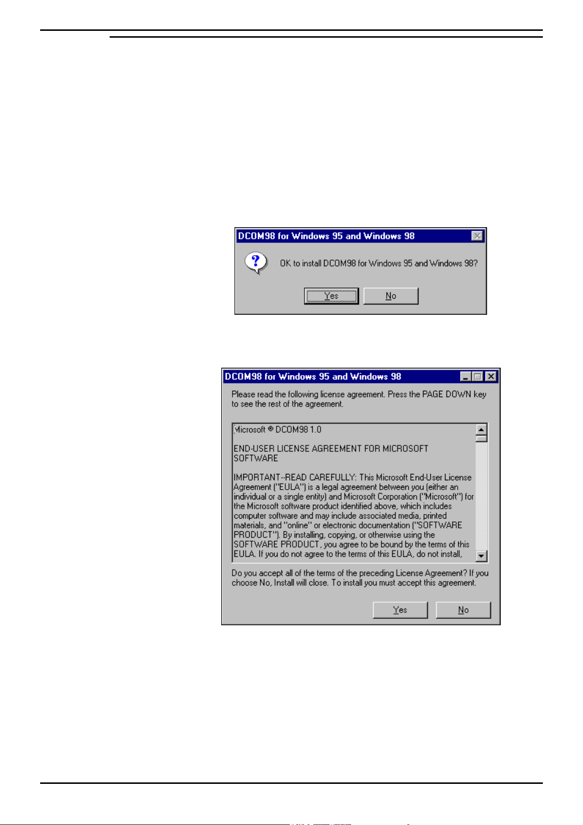
Install INDeX CCM Applications INDeX CCM Server Applications
INDeX Report Client
1. From the INDeX Install Wizard screen, select INDeX Report Client:
2. Click Install.
3. From the Welcome screen, click Next to continue.
4. Middleware component checks the version number of the relevant Server
applications required when running the Client application.
5. Type the name of the PC where the Server application resides or click Search
and select from the list. Type Administrator as the User name and type the
Password if one specified. Click OK to continue. You may need to enter the
information twice depending upon the Server dependencies.
6. When installing this application on Window95/98 the following screen appears:
7. Click Yes to proceed to the following screen:
8. Click Yes to accept the License Agreement.
9. From the Installation Complete, click Finish to complete the installation.
INDeX Contact Centre Modules Page 68
Installation & Maintenance 38HBK00001SCM - Issue 11 (05/01)
Page 69
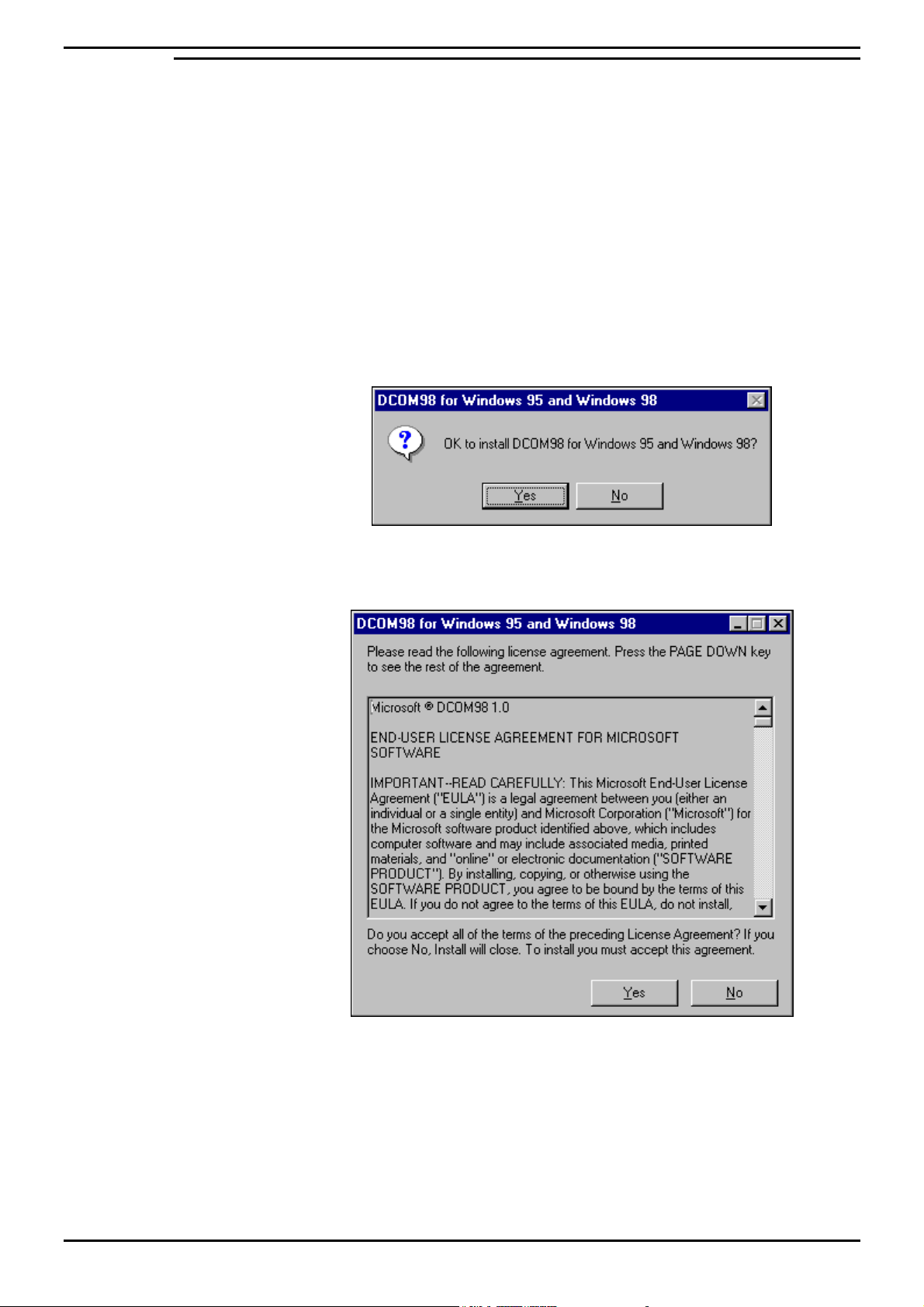
Install INDeX CCM Applications INDeX CCM Server Applications
INDeX Wallboard Client
1. From the INDeX Install Wizard screen, select INDeX Wallboard Client:
2. Click Install.
3. From the Welcome screen, click Next to continue.
4. Middleware component checks the version number of the relevant Server
applications required when running the Client application.
5. Type the name of the PC where the Server application resides or click Search
and select from the list. Type Administrator as the User name and type the
Password if one specified. Click OK to continue. You may need to enter the
information twice depending upon the Server dependencies.
6. When installing this application on Window95/98 the following screen appears:
7. Click Yes to proceed to the following screen:
8. Click Yes to accept the License Agreement.
9. From the Installation Complete, click Finish to complete the installation.
INDeX Contact Centre Modules Page 69
Installation & Maintenance 38HBK00001SCM - Issue 11 (05/01)
Page 70

Install INDeX CCM Applications Trouble Shooting
Trouble Shooting
This section details how to correct many common problems, however as a last
resort read the appropriate manual.
INDeX CCM Installation
1. Whenever anything is loaded from the I386 directory on a Windows NT4
installation CD, re-installation of NT4 Service Pack 6a is NECESSARY.
2. On the Server PC, ensure that the guest account is enabled. Also ensure that
the C drive is shared with the names ‘C’ and ‘SDXSHARE’.
3. If, for whatever reason, the Server PC has to be renamed from the default name
(ArchiverSQL), be aware that Microsoft SQL cannot be guaranteed to operate
correctly if a name that includes spaces is used. Also be sure to rename the
server fields in the ODBC system DSN’s for SDXArchiver as well as
SDXRepository.
4. Only pilot numbers are regarded to be DDI numbers. When reporting on DDI
numbers any DDI number that is not a pilot number cannot be reported on.
INDeX CCM Client applications
1. It is possible that a Client application will NOT automatically find the INDeX
Access Manager/INDeX Delta Server, if the Client application and INDeX
Access Manager/INDeX Delta Server are on PCs on different networks. When
this happens, click the ‘Advanced’ button (from Find Server screen) and select
the option to enable the name of the PC running the INDeX Access
Manager/INDeX Delta Server to be typed in.
2. When using Microsoft Windows 98, for Client applications mapping a drive to
the C drive on the Server PC will speed up Server discovery.
3. When using a Global/Seltek Voice Manager for queuing which uses the
traditional pickup method, the number of calls presented along with the answer
time statistics for an agent/agent group may not be as expected.
INDeX Taskbar
1. After creating new Users on the INDeX Taskbar, the INDeX Taskbar on the
Server needs to be restarted. If an INDeX Wallboard Server is running on the
Server this will also need to be restarted.
INDeX Report Manager
1. If the IPX/SPX protocol is being used to connect the INDeX Report Client to a
server and the INDeX Report Client takes longer than a minute to start then try
changing the frame type.
2. To be sure that the INDeX Archiver is passing information into the database it is
a good idea to keep the status window displayed.
3. From the Document Agent Server Options screen, you MUST set the
Performance [Number of tasks allowed to run concurrently], attribute to 1. This
allows the overlapped scheduled reports, to run correctly.
INDeX Wallboard Server/Client
1 On the INDeX Wallboard Server/Client, scheduled messages can only be
removed from the schedule by a User with a higher access level than the User
that scheduled the message or by the user that scheduled the message. It
therefore follows that if a user with Administrator access rights has scheduled a
message then only that User can remove that message from the schedule.
INDeX Contact Centre Modules Page 70
Installation & Maintenance 38HBK00001SCM - Issue 11 (05/01)
Page 71
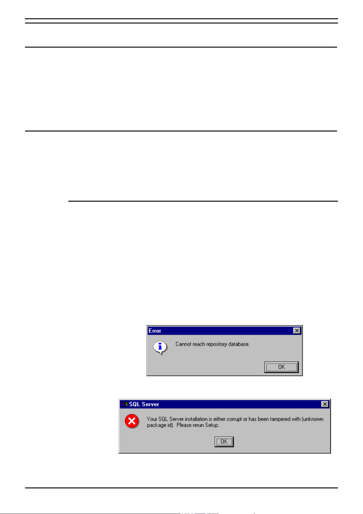
Change Server PC Name Overview
Change Server PC Name
Overview
It is vital that the Server PC used to run the INDeX CCM modules is called
ARCHIVERSQL whilst installing the applications. Once the installation is complete,
change the PC name and workgroup name if desired, as detailed in this section,
prior to connecting the PC to the network.
The following procedure has to be performed after the INDeX CCM applications
have been installed on the relevant PCs. However you must ensure none of the
INDeX CCM applications are running.
Server PC
To change the Server PC name the following procedures have to be performed:
1. Change the Server PC Name as detailed below
2. Change the ODBC Setting for both the SDXArchiver and SDXRepository
databases as detailed in “Changing the ODBC Settings” on page 74;
3. Register the new SQL 7.0 Server.
Change Server PC Name
If there is another ARCHIVERSQL PC on the Network, then install the INDeX CCM
applications without the PC plugged to the Network.
1. From the Windows taskbar, click Start, point to Settings and select Control
Panel.
2. From the Control Panel, double click Network,
3. From the Identification tab. Click Change.
4. Type your computer name as required. Click OK.
5. From the Identification tab, click OK to confirm.
6. When prompted, click Yes to restart the PC.
7. Once the PC has restarted the following screen may appear:
8. Click OK. The following screen also appears:
10. Click OK. You must register the new PC Server name.
11. Close all the INDeX CCM applications.
INDeX Contact Centre Modules Page 71
Installation & Maintenance 38HBK00001SCM - Issue 11 (05/01)
Page 72
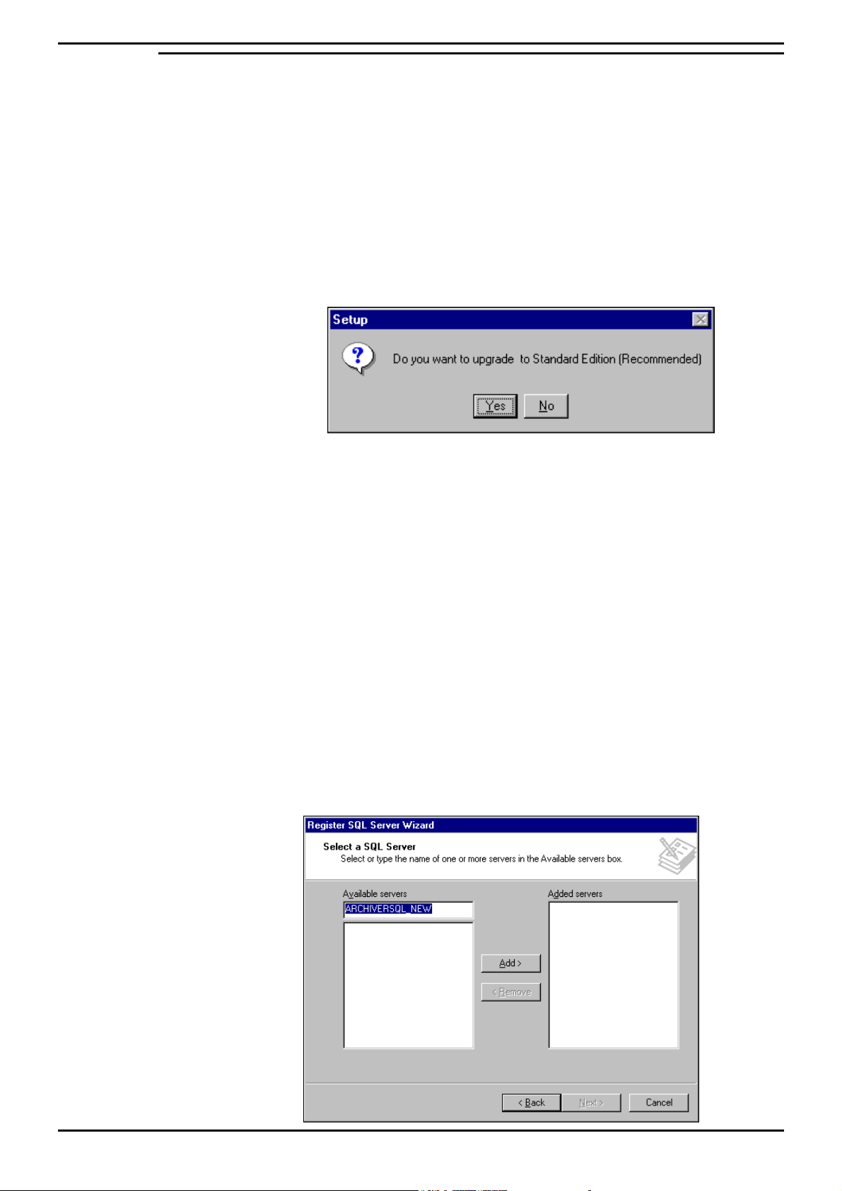
Change Server PC Name Server PC
Registering Server (SQL Server 7.0)
When you run SQL Server Enterprise Manager for the first time, it registers the local
server running SQL Server automatically. If you change the name of the PC Server,
you need to update the SQL 7.0 Setup files and run the Register Server Wizard to
register the new Server.
1. Insert the SQL 7.0 Server CD in the CD ROM drive.
2. From the Microsoft SQL Server Automenu screen click Install SQL Server 7.0
Components.
4. From the Install SQL Server 7.0 Components screen select Database Server –
Standard Edition.
5. Ensure “Local Install – Install to the Local Machine” is selected and then click
Next, the following screen appears:
6. Click Yes to upgrade the SQL Server 7.0 Setup.
7. From Setup Complete screen, click Finish.
8. Click Exit to close the SQL Server Automenu. Restart the PC.
Once the PC is rebooted You must register the server before you can administer
and manage it by using SQL Server Enterprise Manager. When you register a
server, you must specify:
– The name of the server.
– The type of security used to log on to the server.
– Your login name and password, if appropriate.
– The name of the group where you want the server to be listed after it is
registered.
1. From the Windows NT Taskbar, click the Start button, point to Programs and
Microsoft SQL Server 7.0 and then select Enterprise Manager.
2. Click (using the right hand mouse button) SQL Server Group and select New
SQL Server Registration, the Register SQL Server Wizard Welcome screen
appears, from which click Next to proceed to the following screen:
INDeX Contact Centre Modules Page 72
Installation & Maintenance 38HBK00001SCM - Issue 11 (05/01)
Page 73
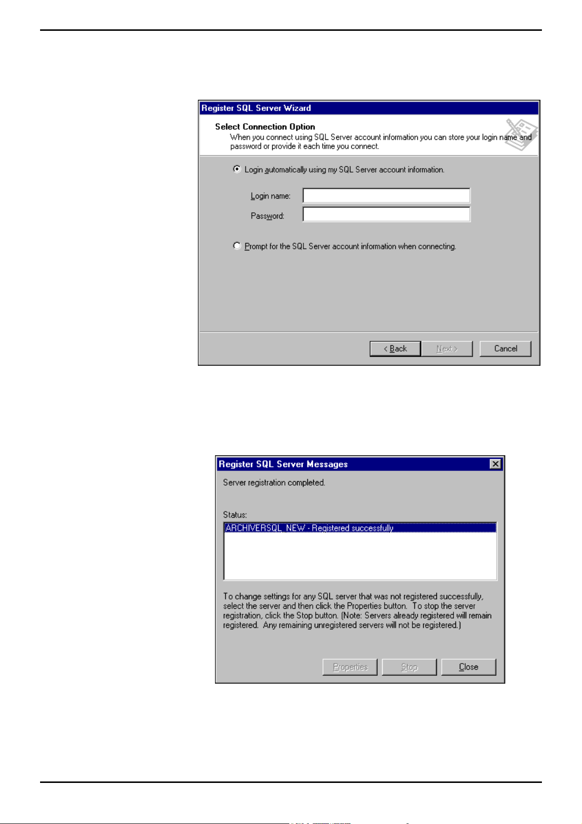
Change Server PC Name Server PC
3. Click Add and then click Next to proceed.
4. From Select an Authentication Mode screen, click to select SQL Server
Authentication, and then click Next to proceed to the following screen:
5. Type sa as the Login name and then click Next to proceed.
6. Ensure SQL Server Group is selected and then click Next to proceed.
7. Click Finish to connect the new server, the following screen appears:
8. Once the Server Registration is complete, click Close.
9. To start SQL Server automatically, select Automatically start SQL Server when
connecting.
INDeX Contact Centre Modules Page 73
Installation & Maintenance 38HBK00001SCM - Issue 11 (05/01)
Page 74
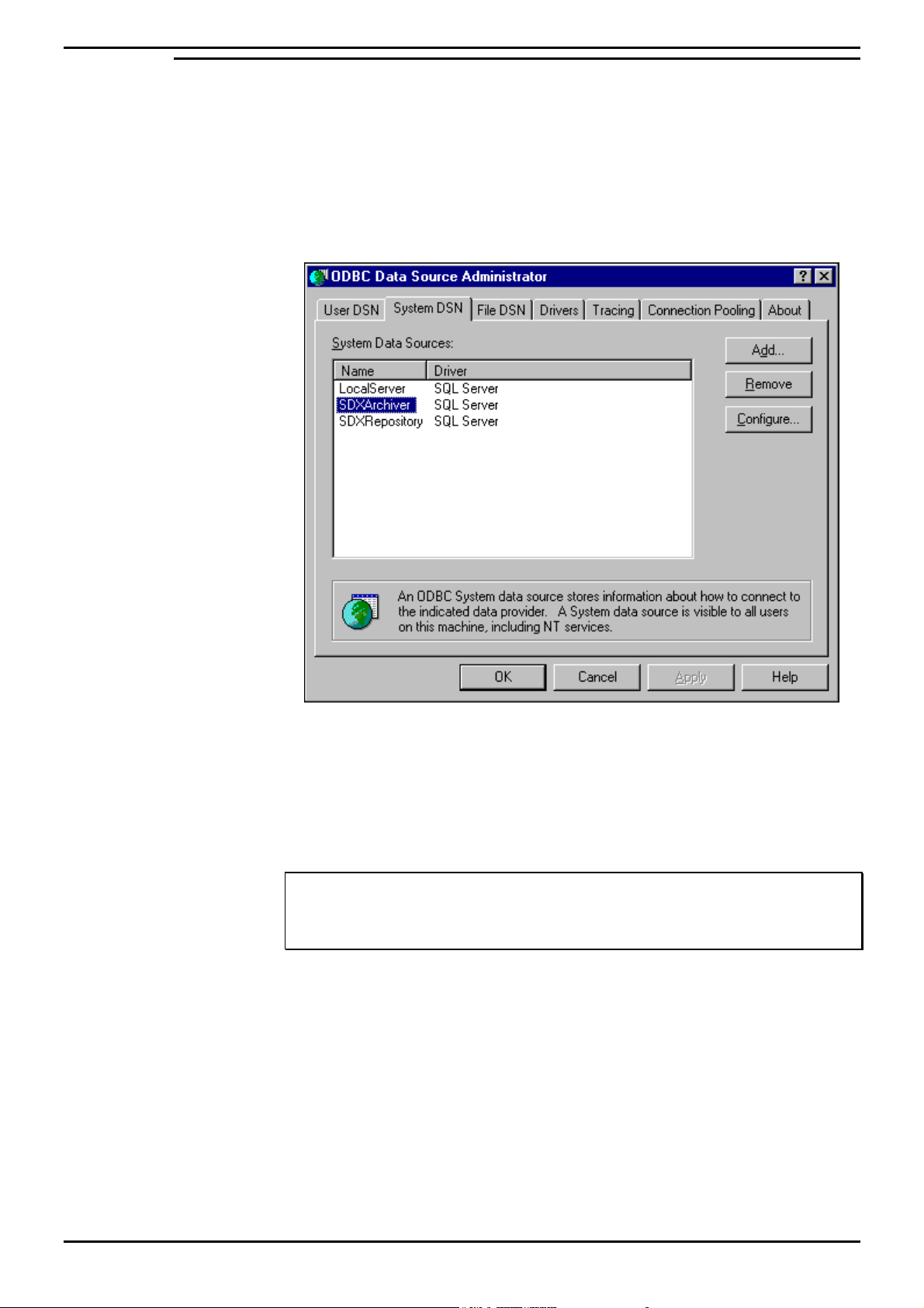
Change Server PC Name Server PC
Changing the ODBC Settings
Ensure you perform the following procedure for both the SDXArchiver and
SDXRepository System Data Sources.
1. From the Windows taskbar, click Start, point to Settings and select Control
Panel.
2. From the Control Panel, open ODBC, and click System DSN tab, the following
screen appears:
The System DSN Tab adds, deletes, or sets up data sources with system DSNs.
These data sources are local to a computer, rather than dedicated to a user. When
the computer's name changes, you must also change the settings of the data
sources. The system, or any user having privileges, can use a data source set up
with a system DSN.
Note
System data sources lists all the system DSNs that includes the name of each DSN and the
driver associated with the DSN. Double-clicking a system DSN displays the driver-specific
data source setup dialog box.
INDeX Contact Centre Modules Page 74
Installation & Maintenance 38HBK00001SCM - Issue 11 (05/01)
Page 75

Change Server PC Name Server PC
3. Select the SDXArichiver and then click Configure.
Note
Configure – Displays the driver-specific data source setup dialog box that enables you to
change the configuration of an existing system data source. You must select the name of
a system data source from the list before choosing the Configure button.
4. In the Description box, enter the new Server name (e.g. if the PC name has
been changed to ARCHIVERSQL123, then in the above screen, SDXArchiver
on server ARCHIVERSQL changes to SDXArchiver on server
ARCHIVERSQL123).
5. In the Server box, enter the new server name (e.g. ARCHIVERSQL123), click
Next, the following screen appears:
6. Ensure “With SQL Server authentication using a login ID and password entered
by the user” is selected.
7. Enter the Login ID as sa, leaving the Password field blank.
8. Click Next, ensure SDXArchiver is selected, click Next.
9. Ensure “Let SQL Server ODBC driver choose the translation method” is
selected.
10. Click Next and then click Finish.
11. Click Test Data Source to ensure the configuration is created and then click OK.
Note
You MUST ensure to repeat the above procedure for the SDXRepository Data Source.
12. From the ODBC Data Source Administrator screen, click OK.
13. Switch the PC off, connect the PC to the Network, and switch the PC back on.
INDeX Contact Centre Modules Page 75
Installation & Maintenance 38HBK00001SCM - Issue 11 (05/01)
Page 76

Change Server PC Name Client PC (Windows NT Workstation)
Client PC (Windows NT Workstation)
Once the Server PC name has changed, you must change the ODBC settings of the
SDXArchiver and SDXRepository databases as detailed in "Changing the ODBC
Settings" on page 74.
Client PC (Windows 98)
When you change the name of the Server PC, the you also need to make the
relevant database changes on the Client PC. This is vital when running the INDeX
Report Client.
Ensure you perform the following procedure for both the SDXArchiver and
SDXRepository System Data Sources.
1. From the Windows taskbar, click Start, point to Settings and select Control
Panel.
2. From the Control Panel, open 32bitODBC, and click System DSN tab, the
following screen appears:
3. Select the SDXArchiver and then click Configure.
4. In the Description box, enter the new Server name (e.g. if the PC name has
been changed to ARCHIVERSQL123, then in the above screen, SDXArchiver
on server ARCHIVERSQL changes to SDXArchiver on server
ARCHIVERSQL123).
5. In the Server box, enter the new server name (e.g. ARCHIVERSQL123), click
OK.
Note
You must ensure you repeat the above procedure for the SDXRepository Data Source.
6. From the ODBC Data Source Administrator screen, click OK.
INDeX Contact Centre Modules Page 76
Installation & Maintenance 38HBK00001SCM - Issue 11 (05/01)
Page 77

PC Upgrade Overview
PC Upgrade
Overview
The INDeX Contact Centre Manager supports a minimum of 5 (using SPC5)
concurrent supervisor positions. However you can increase the number of clients,
by upgrading to either the SPC10 or SPC20.
This section explains, in detail, the procedures of transferring the relevant data as
well as the SDXArchiver and SDXRepository database from a lower Server PC
specification to a higher Server PC specification (e.g. SPC5 to SPC10/SPC20).
The same procedure is applicable when transferring the data from an earlier version
of the INDeX CCM Server PC to SPC5/10/20.
To upgrade to a higher Server PC specification, as your Server PC within the
network, you need to:
– Change the name of the Source PC as detailed in “Change Server PC Name”
on page 71
– Transfer the Wallboard Server Database from Source PC to Destination PC;
– Copy INDeX Call Centre View folder from Source PC to Destination PC;
– Copy INDeX Taskbar Login Data folder from Source PC to Destination PC;
– Transfer the SDXArchiver Database from Source PC to Destination PC.
Note
During this process you must ensure NONE of the INDeX CCM applications are running.
INDeX Wallboard Server Database Transfer
1. From the Source Server PC, map a drive to the Destination Server PC (e.g.
\\newserver\c) as detailed in "Map Network Drive" on page 41.
2. From the Source Server PC, using Windows NT Explorer, copy "SDXWB.ini”
“DEVICES.mdb", "WALLBRD.mdb" and "AggregateVars.mdb" to the same
location on the Destination Server PC (i.e. C:\lucent\WBSERVER).
INDeX Call Centre View Database Transfer
1. From the Source Server PC, map a drive to the Destination Server PC (e.g.
\\newserver\c) as detailed in "Map Network Drive" on page 41.
2. From the Source Server PC, using Windows NT Explorer, copy LANGUAGES,
MUGSHOTS and OPERATOR folders to Destination Server PC (i.e.
C:\lucent\CCV).
INDeX Taskbar Login Data Transfer
1. From the Source Server PC, map a drive to the Destination Server PC (e.g.
\\newserver\c) as detailed in "Map Network Drive" on page 41.
2. From the Source Server PC, using Windows NT Explorer, copy DATA folder to
Destination Server PC (i.e. C:\SDX\Data).
INDeX Contact Centre Modules Page 77
Installation & Maintenance 38HBK00001SCM - Issue 11 (05/01)
Page 78

Administering Database Backing Up and Restoring Overview
Administering Database
Backing Up and Restoring Overview
The backup and restore component of Microsoft® SQL Server™ provides an
important safeguard for protecting critical data stored in SQL Server databases.
Backing up and restoring a database allows for the complete restoration of data
over a wide range of potential system problems:
• Media failure
If one or more of the disk drives holding a database fail, you are faced with a
complete loss of data unless you can restore an earlier copy of the data.
• User errors
If a user or application either unintentionally or maliciously makes a large
number of invalid modifications to data, the best way to deal with the problem
may be to restore the data to a point in time before the modifications were
made.
• Permanent loss of a server
If a server is disabled permanently, or a site is lost to a natural disaster, you
may need to activate a warm standby server or restore a copy of a database to
another server.
Additionally, backing up and restoring databases is useful for non-system problems,
such as moving or copying a database from one server to another. Backing up a
database from one computer, and restoring the database to another can make a
copy of a database made quickly and easily.
Backing Up a Database
Backing up a database makes a copy of a database, which can be used to restore
the database if it is lost. Backing up a database copies everything in the database.
A backup operates like a fuzzy snapshot taken of a database :
A database backup records the complete state of the data in the database at the
time the backup operation completes.
Restoring a Database
Restoring a database backup returns the database to the same state it was in when
the backup was created. Any incomplete transactions in the database backup,
(transactions that were not complete when the backup operation completed
originally), are rolled back to ensure the database remains consistent.
INDeX Contact Centre Modules Page 78
Installation & Maintenance 38HBK00001SCM - Issue 11 (05/01)
Page 79

Administering Database Creating Database Backup
Creating Database Backup
When creating a database backup, the backup operation copies only the data in the
database to the backup file; it does not copy out unused space in the database.
Because the database backup contains only the actual data in the database, not
any empty space, the database backup is likely to be smaller than the database
itself.
If you are producing database backups only, the backup interval should be long
enough to keep the backup overhead from affecting production work, yet short
enough to prevent the loss of significant amounts of data. Databases that do not
contain critical data and have few modifications can be backed up on a weekly or
biweekly basis. Data that is more critical or more volatile may need to be backed up
daily, or even more frequently. Some databases that are usually read-only may
need to be backed up only after a periodic refresh with new data.
Note
If any files are added or removed from a database, a database backup should be created
immediately.
Database - Complete
During the installation of the Report Manager, Backup administration is configured
and the SDXArchiver database is automatically backed-up in the D:\MSSQL7 drive.
To change the location of the backup destination to the Tape Drive, perform the
following procedure.
Note
Ensure the Tape drive is already installed to be able to change the destination of the
database backup drive.
1. From the Windows NT Taskbar, click the Start button, point to Programs and
Microsoft SQL Server 7.0 and then select Enterprise Manager, the following
screen appears:
INDeX Contact Centre Modules Page 79
Installation & Maintenance 38HBK00001SCM - Issue 11 (05/01)
Page 80
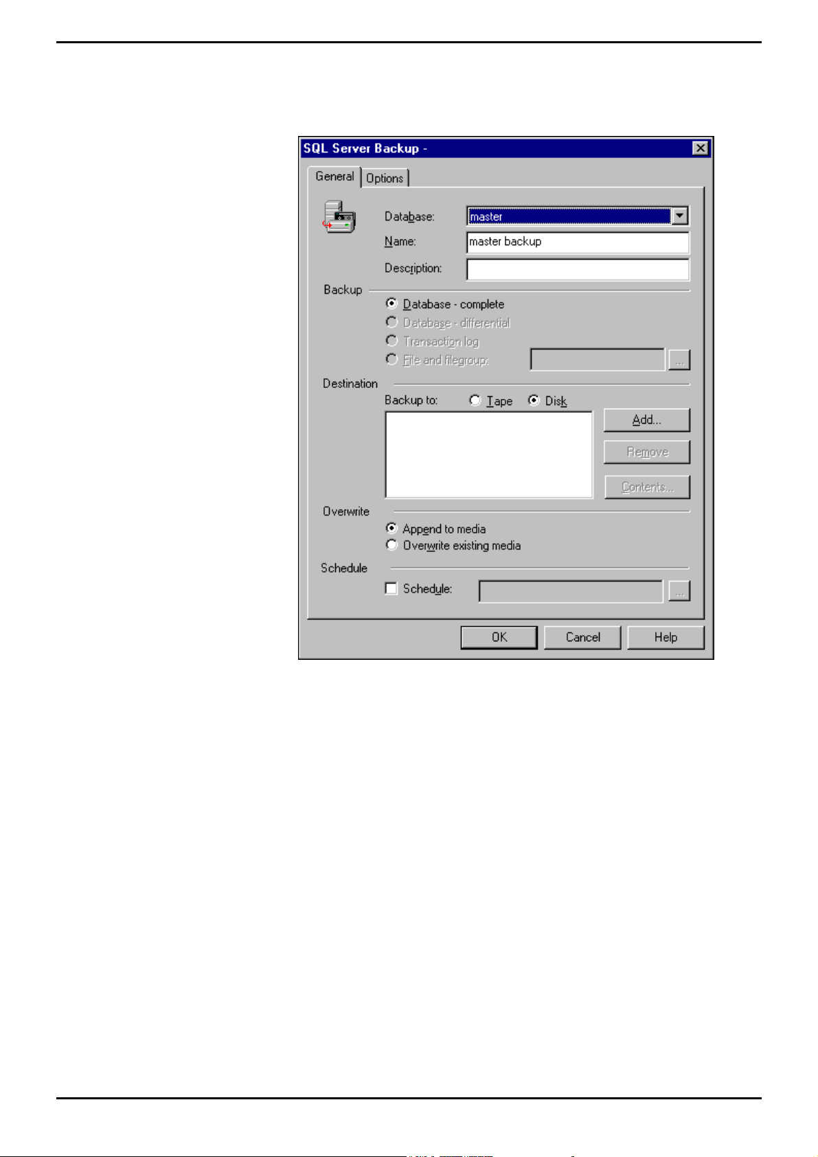
Administering Database Creating Database Backup
2. Highlight the Server item (i.e. ARCHIVERSQL in the above screen) on the
explorer tree and then from Tools menu, select Backup Database, the
following screen appears:
3. Using the pull down arrow associated with Database field, select SDXArchiver
database.
4. From the list of Backup options, ensure Database – complete is selected. This
is recommended when backing up the database for the first time. Refer to
“Database – Differential” on page 81 to select the Differential Backup option.
INDeX Contact Centre Modules Page 80
Installation & Maintenance 38HBK00001SCM - Issue 11 (05/01)
Page 81

Administering Database Creating Database Backup
5. Click to select Tape for the Backup Destination and then click Add. Click to
select Tape and then from the pull down arrow select Tape as displayed in the
following screen:
6. Click OK.
7. From the SQL Server Backup screen, select Overwrite – Append to media
option. Click OK.
8. Once the database has been copied, the following screen appears:
9. Click OK.
Database – Differential
You can supplement database backups by using differential database backups that
record only the changes made to the database after the last database backup. For
example, you can create a database backup nightly, and create differential
database backups at shorter intervals, such as every four hours.
Each differential database backup records all modifications made to a database
after the last database backup, not just the changes made after the last differential
database backup. If you create a database backup, followed by multiple differential
database backups, you do not have to restore the database backup followed by all
of the differential database backups; you only have to restore the database backup
and the last differential database backup created.
Perform the procedure detailed in the “Error! Reference source not found.” on
page Error! Bookmark not defined., however select Database – Differential as
the Backup option.
INDeX Contact Centre Modules Page 81
Installation & Maintenance 38HBK00001SCM - Issue 11 (05/01)
Page 82

Administering Database Creating Database Backup
Automatic Backup
You can automate administrative tasks using SQL Server Agent jobs. You define
the job one time, yet you can run it many times.
By default the SDXArchiver database is automatically backed up on to the
D:\MSSQL7 disk drive. This section details the procedure required to automatically
enable the Tape drive as the backup device. Once the Automatic Tape Drive
Backup has been enabled it is advisable that you disable the backup jobto disk
drive as detailed in this section.
1. From the Windows NT Taskbar, click the Start button, point to Programs and
Microsoft SQL Server 7.0 and then select Enterprise Manager, the following
screen appears:
2. Click the Server item (i.e. ARCHIVERSQL in the above screen) on the explorer
tree, then click Management folder, from which SQL Server Agent and then
click Jobs as shown in the following screen:
INDeX Contact Centre Modules Page 82
Installation & Maintenance 38HBK00001SCM - Issue 11 (05/01)
Page 83
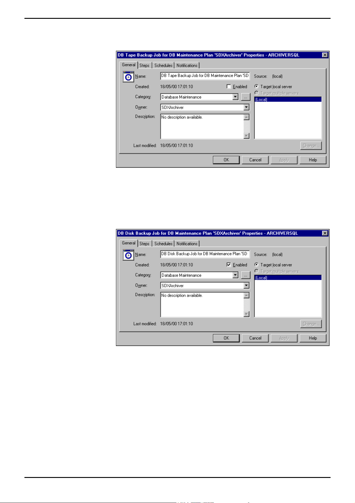
Administering Database Creating Database Backup
3. Click “DB Tape Backup Job for DB Maintenance Plan ‘SDXArchiver’” (using the
right hand mouse button) and select Properties, the following screen appears:
4. Click to select Enabled, click Apply and then OK.
5. To disable the Disk Backup, click “DB Disk Backup Job for DB Maintenance
Plan ‘SDXArchiver’” (using the right hand mouse button) and select Properties,
the following screen appears:
6. Remove tick from Enabled, click Apply and then OK.
INDeX Contact Centre Modules Page 83
Installation & Maintenance 38HBK00001SCM - Issue 11 (05/01)
Page 84

Administering Database Creating Database Backup
Backup to a Remote Device
To enable the backing up of a SQL database to a remote backup device residing on
a Windows NT PC the following procedures must be carried out:
On the Source SQL Server PC:
1. Using User Manager, create a New User and grant the newly created User the
rights to log on as a Service;
2. For any NTFS drives that contain SQL files or SQL devices, ensure that the
Newly created user has the right to read, write, execute and delete
3. Configure the MSSQLServer Service.
On the Destination Windows NT PC
1. Using User Manager, create a New User (with the same name as the one on
the Source PC), specifying a password if desired;
2. Configure the Drive/Directory, in which the backup device is to reside, to be
shared;
3. For any NTFS drives that contain SQL files or SQL devices, ensure that the new
user has Full Control Access;
4. Using the SQL Server 7.0 Enterprise Manager, configure the Backup Database
as detailed in “Creating Database Backup” on page 79, ensuring the destination
backup device is set to this PC.
Create a New User
User Manager enables you to manage security for a computer running Windows NT.
With User Manager, you can create and manage user accounts, create and manage
groups and manage the Windows NT's accounts (passwords), user rights and
auditing policies.
1. From the Windows taskbar, click Start, point to Programs and from
Administrative Tools (Common), select User Manager.
2. From the User menu, select New User, the following screen appears:
3. Type the appropriate information:
–In Username, type a user name;
–In Full Name, type the user's complete name;
–In Description, type a description of the user or the user account;
– In both Password and Confirm Password, type a password of up to 14
characters (if desired);
Note
A user name cannot be identical to any other user or group name of the computer being
administered.
4. Click to clear User Must Change Password at Next Login.
5. Click to select User Cannot Change Password and Password Never Expires.
6. Click Add and then click Close..
7. From the Policies Menu, select User Rights. Click to select Show Advanced
User Rights.
8. Click OK. From the User menu, select Exit to close the User Manager
application.
INDeX Contact Centre Modules Page 84
Installation & Maintenance 38HBK00001SCM - Issue 11 (05/01)
Page 85

Administering Database Creating Database Backup
Configure the NTFS Drive
1. Double click My Computer.
2. Click (using the right hand mouse button) the NTFS Drive (that contains SQL
Devices and Database), select Properties from the pull down menu.
3. Click the Security tab and click Permissions, ensure that the newly created user
has Full Control Access (i.e. the right to read, write execute and delete).
4. If the newly created user name is not listed, click Add.
5. From Add Users and Groups screen, select the new user name and then select
Full Control for Type of Access. Click OK.
6. From Directory Permissions screen click OK.
7. From Drive Properties screen, click OK. Close My Computer.
Configure MSSQLServer Service
1. From the Windows NT taskbar, click Start, point to Setting and select Control
Panel.
2. From the Control Panel, double click Services. Select MSSQLServer and then
click Startup.
3. By default, this service is set to Log On As: System Account.
4. Click to select This Account. Click Add User screen appears.
5. Select the new user name, click Add and then OK.
6. Enter the User’s Password (if one was specified) and Confirm Password and
then click OK.
7. With the MSSQLServer service highlighted click Stop and then click Start.
INDeX Contact Centre Modules Page 85
Installation & Maintenance 38HBK00001SCM - Issue 11 (05/01)
Page 86

Administering Database Restoring a Database Backup
Restoring a Database Backup
Restoring a database backup returns the database to the same state it was in when
the backup was created. When restoring a database, SQL Server re-creates the
database and all of its associated files automatically by performing these steps:
1. All of the data from the backup is copied into the database; the rest of the
database is created as empty space.
2. Any incomplete transactions in the database backup, (transactions that were not
complete when the backup operation completed originally), are rolled back
(undone) to ensure the database remains consistent.
This process ensures that the restored database is a copy of the database as it
existed when the backup operation completed, except that all incomplete
transactions have been rolled back. This is required to restore the integrity of the
database.
Additionally, to prevent overwriting a database unintentionally, the restore operation
can perform a safety check automatically. The restore operation fails if:
– The database named in the restore operation already exists on the server and
the database name does not match the database name recorded in the backup
set.
– The database named in the restore operation already exists on the server but it
is not the same database as the database contained in the database backup.
For example, the database names are the same but each database was created
differently.
– One or more files need to be created automatically by the restore operation
(regardless of whether the database already exists) but files with the same file
name as those that need to be created already exist.
These safety checks can be disabled if the intention is to overwrite another
database.
INDeX Contact Centre Modules Page 86
Installation & Maintenance 38HBK00001SCM - Issue 11 (05/01)
Page 87

Administering Database Restoring a Database Backup
This section details the procedure that is required to restore the database from the
Tape Drive.
1. From the Windows NT Taskbar, click the Start button, point to Programs and
Microsoft SQL Server 7.0 and then select Enterprise Manager, the following
screen appears:
2. Highlight the Server item (i.e. ARCHIVERSQL in the above screen) on the
explorer tree and then from Tools menu, select Restore Database. Select the
SDXArchiver database as shown in the following screen:
3. Click OK.
4. Once the Restore of the database is complete, the following screen appears:
5. Click OK.
INDeX Contact Centre Modules Page 87
Installation & Maintenance 38HBK00001SCM - Issue 11 (05/01)
Page 88

Administering Database Restoring a Database to a Different PC
Restoring a Database to a Different PC
This is to help those who are attempting to restore a previously backed up database
onto a different machine. The following steps should be completed from the new
machine within SQL Enterprise Manager after you have restored the database.
3. Within Enterprise Manager expand the Security folder.
4. Click on Logins and then Right mouse click on the SDXArchiver and select
properties.
5. Click on the Database Access Tab.
6. Tick the box next to SDXArchiver. Whilst this is highlighted ensure that the two
boxes 'PUBLIC' and ’DB_OWNER' are checked in the lower half of the window.
7. Tick the box next to SDXrepository. Whilst this is highlighted ensure that the
two boxes 'PUBLIC' and ’DB_OWNER' are checked in the lower half of the
window
8. Close the properties window, exit SQL Enterprise Manager.
Expand a Database
Microsoft® SQL Server™ can expand a database automatically, according to
growth parameters defined when the database was created. However this feature
is disabled during the installation of the INDeX Report Manager. You can manually
expand the SDXARCHIVER database by allocating additional file space on an
existing database file
When expanding a database, you must increase the size of the database by at least
1 megabyte (MB). When a database is expanded, the new space is made
immediately available to the data file.
During the INDeX Report Manager installation, 2GB database is created on the D:\
drive. It is advisable to increase the size of the database as follows:
– For SPC5 expand the database to: 5GB
– For SPC10 expand the database to: 20GB
– For SPC20 expand the database to: 41GB
When the database is 80% full you will be presented by a Free space Disk warning.
Once it gets to 95% another message is displayed warning you that it will start
clearing the oldest day’s data.
This section details the procedure required to expand the SDXArchiver database.
1. From the Windows NT Taskbar, click the Start button, point to Programs and
Microsoft SQL Server 7.0 and then select Enterprise Manager.
2. Expand the Server group (i.e. SQL Server Group), expand the Server (i.e.
ARCHIVERSQL) and then the Databases, as displayed in the screen on the
following page:
INDeX Contact Centre Modules Page 88
Installation & Maintenance 38HBK00001SCM - Issue 11 (05/01)
Page 89
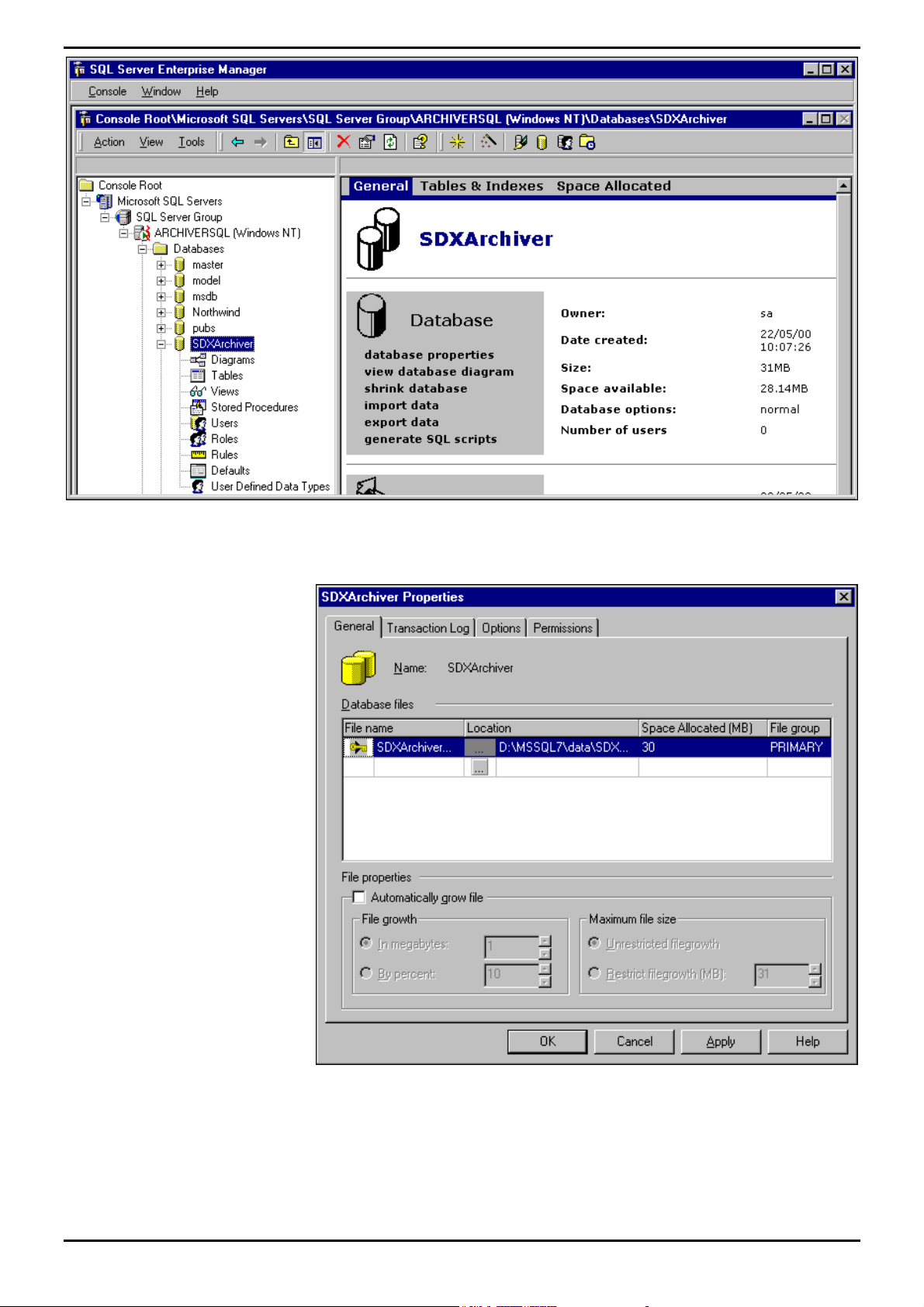
Administering Database Expand a Database
3. Click (using the right hand mouse button) SDXArchiver and then select
Properties, the following screen appears:
4. In the Space Allocated (MB) enter the appropriate number, click Apply and
then click OK.
INDeX Contact Centre Modules Page 89
Installation & Maintenance 38HBK00001SCM - Issue 11 (05/01)
Page 90

INDeX Telephone System Requirements
INDeX Telephone System
Requirements
This section assumes that the installer is familiar with the basic programming of the
INDeX Telephone System and the INDeX Programming manual is available.
– INDeX Telephone System Software must be Level 8.0+.
– When using INDeX CCM applications, you can only use INDeX 2050/DT5
Handsets with ACD Agents logged on and Turret devices. However INDeX
Report Client obtains information on all devices.
– Server Licence numbers for INDeX applications are:
Server Licence No. INDeX CCM application
23 INDeX Call Centre View
24 INDeX Wallboard Server
25 INDeX Archiver
27 INDeX Report Client
Agent Licence Pack
The relevant agent Licence pack is required if information on individual agent's
status and activity is to be displayed on INDeX Call Centre View screens as well as
Wallboard devices.
The relevant agent Licence pack is required if information on individual agent's
status is to be reported upon by the INDeX Report Manager.
Call Activity is available for all INDeX users without the Agent Licence Pack.
Naming Directory Numbers
Since the INDeX Telephone System programming is reflected within the INDeX
Contact Centre Manager applications, it is important to name the directory numbers
(i.e. Agents, Groups, Trunks, DDIs, etc).
28 INDeX Report Designer
29 Agent Numbers (5)
30 Agent Number (1)
It is also highly recommended that the directory number names be unique to aid
identification of specific directory number within the Standard Reports.
Where directory numbers of a specific type are unnamed, or where more than one
directory number as a specific type has the same name, the Standard Reports will
group data for those directory numbers as a single entity (e.g. all unnamed agents
will be grouped together as a single agent called "No Name", and all DDIs named
"Company DDI" will be grouped together as a single DDI called "Company DDI,
etc.).
INDeX Contact Centre Modules Page 90
Installation & Maintenance 38HBK00001SCM - Issue 11 (05/01)
Page 91

INDeX Telephone System Requirements
If the directory numbers have not been named, then the terminology for the
directory numbers implemented in the INDeX Contact Centre Manager applications
is:
Agent – ACD Agent (XXXX*) – XXXX
Group – Agt Group (XXXX) – XXXX
Trunk Grp – Trunk GP (XXXX) – XXXX
Tie Line (Trunk) – Tie Line (XXXX) – XXXX
DPNSS (Trunk) – DPNSS (XXXX) – XXXX
DASS (Trunk) – DASS (XXXX) – XXXX
Alog (TWC) – Alog (TWC) (XXXX) – XXXX
Pilot (Trunk) – Pilot (XXXX) – XXXX
* Where XXXX is the directory number.
Group Reporting
When configuring the INDeX it is important to understand how calls are attributed to
groups on the Call Centre View, Wallboards and Report Manager.
INDeX-Net in the Contact Centre Environment
Staff Management is a LOCAL issue hence all real time and historic analysis for
teams will require local CCM’s.
Traffic Management is a GLOBAL issue. Therefore in an INDeX-Net configuration
calls waiting across an entire network (queued) are displayed on all Call Centre
View implementations across INDeX-Net.
Call Centre View and Wallboard Manager
The INDeX Call Centre View and Wallboard Manager products report on groups
directly derived from the INDeX Database. Agents and Trunks may be reported on
in as many groups as they are members of within the INDeX. It is important however
to understand how statistics for these groups are derived and it is important for the
user of the system to understand these reporting structures. These are defined
below
Call Totals and average durations for Groups are calculated by totalling the
statistics for the members of group. Should an agent or group be a member of
multiple groups, their call totals will appear in multiple groups.
Lost Calls are only attributed to the initial target agent group i.e. Initial INDeX ring
group. Lost calls are also attributed to Trunk Lines, Trunk Groups and Pilot
Numbers.
Agent Status Information for a group shows the number of agents or trunks within a
given group, which are in each state.
Agent Statistics for:
Calls Waiting, PCA, GOS, Longest Wait, LWait (Ans), L Wait (Lost),
Overflowed to/From statistics are only incremented for calls which are directly
presented to that agent group. That is they only increment where the agent
group is used for Call routing purposes.
INDeX Contact Centre Modules Page 91
Installation & Maintenance 38HBK00001SCM - Issue 11 (05/01)
Page 92

INDeX Telephone System Requirements
Trunk Statistics for:
Calls waiting and Lost are calculated by totalling the statistics for the members
of the trunk group.
PCA and GOS are calculated for each trunk group after totaling answered calls
(plus lost for GOS) for the members of the trunk group.
LWait (Lost) and LWait (Ans) reflect the longest wait of all those logged
against any member of the trunk group.
INDeX Report Manager
The INDeX CCM has two concepts for historic reporting that cater for different views
a supervisor may require of their contact centre. One type of report referred to as
‘Target’ reports, provides analysis based on where the call was presented and
relates closely to the manner in which the INDeX call routing has been configured.
The second type of report, referred to as ‘collective’ reports, is based on arbitrary
sets of agents and need not necessarily correspond to the manner in which switch
call routing is programmed.
INDeX CCM Reporting characteristics associated with INDeX Voice Manager
The following conditions apply to the initial answer/ lost segment of calls which were
first presented to the Voice Manager (VM) (e.g. Voice Mail front ended systems):
1. Trunk/DDI – Call remains unanswered until answered by non-Voice Manager
device or if terminated within 3rd party Voice Mail, or encountered an
"Answered" flag in INDeX Voice Manager.
2. 3rd Party Voice Mail – Answered if Voice Mail connects, lost by Voice Mail if
caller hangs up before Voice Mail can answer.
3. INDeX Voice Manager – Calls will only be registered as answered when the
INDeX Voice Manager has successfully processed the call (passed an
"Answered" flag in Call Flow)
Note
A call, which is first connected to INDeX Voice Manager but not deemed answered by VM, will
be considered lost, but not refused if terminated during first connection to IVM.
4. Agent/Agent Group – Designation of answered and lost calls is directly
dependent upon clause 1.
5. If a call was lost whilst being transferred by Voice Manager, the lost call
statistics will be designated to the transfer target. Calls lost whilst alerting or
connected to Voice Manager will be deemed lost by the Voice Manager device
or group.
6. A call successfully transferred by Voice Manager will be treated as a new
incoming call by trunks, DDI and Agents, but transferred by Voice Manager
devices.
INDeX Contact Centre Modules Page 92
Installation & Maintenance 38HBK00001SCM - Issue 11 (05/01)
Page 93

INDeX Telephone System Requirements
Tie Line Statistics
Tie Line Statistics are presented from the perspective of the INDeX Telephone
System to which Access Manager/Delta Server is connected.
Statistics for Tie Lines and groups of Tie Line reflect traffic across respective
directory numbers (trunk and trunk groups).
Each of the following tables represent a different call category as indicated in top left
hand corner (e.g. Internal Answered, Incoming Answered, etc.).
The information in all boxes reflects the effect of the relevant call category on the
statistics in each of columns for the call party represented in the rows.
Internal Tie Line
The relevant rows (i.e. Source or Recipient) are dependent upon the direction of the
call.
Internal Answered Status Presented Answered Avg I/C Lost Refused Outgoing Avg O/G Internal
Source Agent Outgoing N/A N/A N/A N/A N/A N/A N/A
Source Tie Line Outgoing N/A N/A N/A N/A N/A N/A N/A N/A
From(+1)
Recipient Tie Line Incoming N/A N/A N/A N/A N/A N/A N/A N/A
Recipient Agent Incoming N/A N/A N/A N/A N/A N/A N/A
Internal Unanswered Status Presented Answered Avg I/C Lost Refused Outgoing Avg O/G Internal
Source Agent Outgoing N/A N/A N/A N/A N/A N/A N/A N/A
Source Tie Line Outgoing N/A N/A N/A N/A N/A N/A N/A N/A
Recipient Tie Line Busy N/A N/A N/A N/A N/A N/A N/A N/A
Recipient Agent Ringing N/A N/A N/A N/A N/A N/A N/A N/A
To(+1)
N/A – Not Applicable;
+1 – Incremented by 1;
INDeX Contact Centre Modules Page 93
Installation & Maintenance 38HBK00001SCM - Issue 11 (05/01)
Page 94

INDeX Telephone System Requirements
External Calls To/From Remote Tie Line
Switch 'A' refers to the INDeX Telephone System directly connected to the PSTN.
Switch 'B' refers to any INDeX Telephone System indirectly (i.e. via Switch 'A')
connected to PSTN via Tie Line.
PSTN Trunks and Switch 'A' statistics are relevant where Access Manager/Delta
Server are connected to Switch 'A'.
Switch 'B' and Agents statistics are relevant where Access Manager/Delta Server
are connected to Switch 'B'.
(gps) – signifies that the relevant agent statistics only affects agent groups.
Incoming Answered Status Presented Answered Avg I/C Lost Refused Outgoing Avg O/G
PSTN Trunks Incoming
+1 +1
N/A N/A N/A N/A N/A
Switch 'A' Tie Line Outgoing N/A N/A N/A N/A N/A
Switch 'B' Tie Line Incoming
Agent Incoming
Incoming Unanswered Status Presented Answered Avg I/C Lost Refused Outgoing Avg O/G
PSTN Trunks Incoming
Switch 'A' Tie Line Outgoing N/A N/A N/A N/A N/A
Switch 'B' Tie Line Busy
Agent Ringing
Outgoing Connected Status Presented Answered Avg I/C Lost Refused Outgoing Avg O/G
Agent Outgoing N/A N/A N/A N/A N/A
Switch 'B' Tie Line Outgoing N/A N/A N/A N/A N/A
Switch 'A' Tie Line Incoming
PSTN Trunks Outgoing N/A N/A N/A N/A N/A
+1 +1 Calculated
+1(gps) +1 Calculated
+1
+1
+1(gps)
+1
N/A N/A
N/A N/A
N/A N/A
N/A N/A N/A N/A N/A N/A
N/A N/A N/A N/A
N/A N/A N/A N/A
+1
+1
+1 +1
N/A N/A N/A
N/A N/A N/A
+1 Calculated
+1
N/A N/A
+1 Calculated
+1
+1 Calculated
N/A
N/A
Outgoing Failed Status Presented Answered Avg I/C Lost Refused Outgoing Avg O/G
Agent Outgoing N/A N/A N/A N/A N/A
Switch 'B' Tie Line Outgoing N/A N/A N/A N/A N/A
Switch 'A' Tie Line Incoming
PSTN Trunks Outgoing N/A N/A N/A N/A N/A
+1
N/A N/A N/A N/A N/A N/A
+1 Calculated
+1
+1
N/A
N/A
N/A – Not Applicable;
+1 – Incremented by 1;
Calculated – Average value re-evaluated
INDeX Contact Centre Modules Page 94
Installation & Maintenance 38HBK00001SCM - Issue 11 (05/01)
Page 95

Wallboard Installation and Maintenance INDeX Wallboard 22
Wallboard Installation and Maintenance
INDeX Wallboard 22
Introduction
The INDeX Wallboard 22 is a two line by 22-character tri-colour Wallboard. It
connects via a multi-drop circuit to the host PC running the INDeX Wallboard Server
application.
The display wallboard consists of the following assemblies.
Housing
A housing which is manufactured from an aluminum extrusion with anti reflective
polycarbonate screen and removable plastic end caps.
Power Supply
9V DC switch mode power supply assembly incorporating an RJ45 chassis mounted
data connector. The power supply is configurable for use from either 120V AC or
240V AC (NOMINAL VOLTAGES) supplies.
Installation
Logic Control Board
Logic control board that receives RS485 serial data from the data RJ45 connector.
Display Board Assembly
Tri-colour display board assembly which consists of three display boards which are
connected one to the other by a fibre optic link. The left-hand display board
receives display data from the logic control board, via a fibre optic link and it outputs
data to the next display board etc.
Each display board consists of decoding and LED row and column circuitry which
drives the LED matrix consisting of 18 5x8 LED blocks.
Before commencing installation, please check from the packing list that all parts are
included.
Packing List
1 x INDeX Wallboard 22
2 x Wall mount brackets
2 x Spun hanging wires
4 x Cavity rawl plugs
4 x Screws
2 x Eyehole bolts
2 x Masonry rawl plugs
2 x Housing clamps
1 x RJ45 Terminal Box
1 x IEC Power lead
Before commencing installation, please take a couple of minutes ensuring that the
final location of the display will be both safe and practical for the customer. Also
check that the power socket provided is suitable for this type of display.
INDeX Contact Centre Modules Page 95
Installation & Maintenance 38HBK00001SCM - Issue 11 (05/01)
Page 96
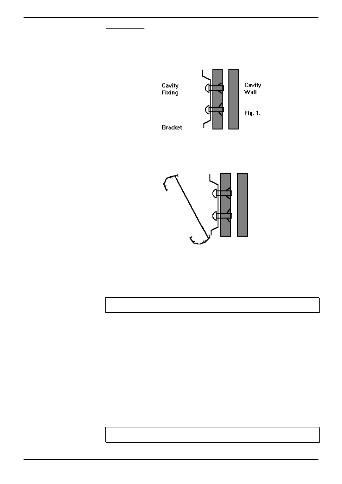
Wallboard Installation and Maintenance INDeX Wallboard 22
Wall Mounting
Once a location has been decided upon, a pencil may be used through the two
holes in the brackets to mark its location onto the wall. Before drilling holes, a
suitable utility detector should be used. Once done, the holes may be drilled and
the brackets mounted using the relevant fixings provided.
Before mounting the display onto the brackets, the network address should be
assigned. The power lead should also be attached prior to mounting.
To mount the display, first hook the bottom of the two brackets into the bottom rear
recess channel of the display. See Fig.2.
Fig. 2
Push the wallboard flat against the wall and push upwards to fully locate the bottom
half into the recess. Now allow the display to fall approximately one inch. The
display should now be safely located onto the two brackets.
To remove a wall mounted display then reverse the above paragraph.
Note
The wallboard position can be adjusted by sliding sideways in either direction.
Ceiling Mounting
Using the mounting kit provided, firstly, drill the 6-mm holes for the eyehole bolts
and secure them into the ceiling. Pass the spun wire chain through the eyeholes
and through the housing clamps and tighten at the required height.
Remove the right hand end cheek of the wallboard by unscrewing the two fixing
screws.
Slide the two nipples on the end of the spun wire chain into the middle groove of the
display housing and replace the end cheek. Centre the display on the hanging
wires. Adjustments can be made by sliding the display to achieve the final level.
Warning
Ensure the ceiling can support the weight of the wallboard prior to fixing.
INDeX Contact Centre Modules Page 96
Installation & Maintenance 38HBK00001SCM - Issue 11 (05/01)
Page 97

Wallboard Installation and Maintenance INDeX Wallboard 22
RS485 Serial Connection
The RJ45, RS485 flying lead is one metre long. It cannot be removed from the
Wallboard; therefore, this must be taken into consideration for the location of the
RJ45 terminal box.
Fit the RJ45 terminal box within one metre of the centre of the Wallboard.
The Wallboard should be connected to the host system by utilising a drop off wiring
configuration (See Figure 3 below).
Fig. 3
All RJ45 sockets should be wired identically with the terminated RJ45 plug on the
final socket with the supplied RJ45 doubler.
Network Addressing
Each display can be configured to display different messages. This is achieved by
allocating each display its own network address. Within each display, there is a
board containing eight dip switches. "Serial Connection & Dip-Switch Details" on
page 99.
INDeX Contact Centre Modules Page 97
Installation & Maintenance 38HBK00001SCM - Issue 11 (05/01)
Page 98
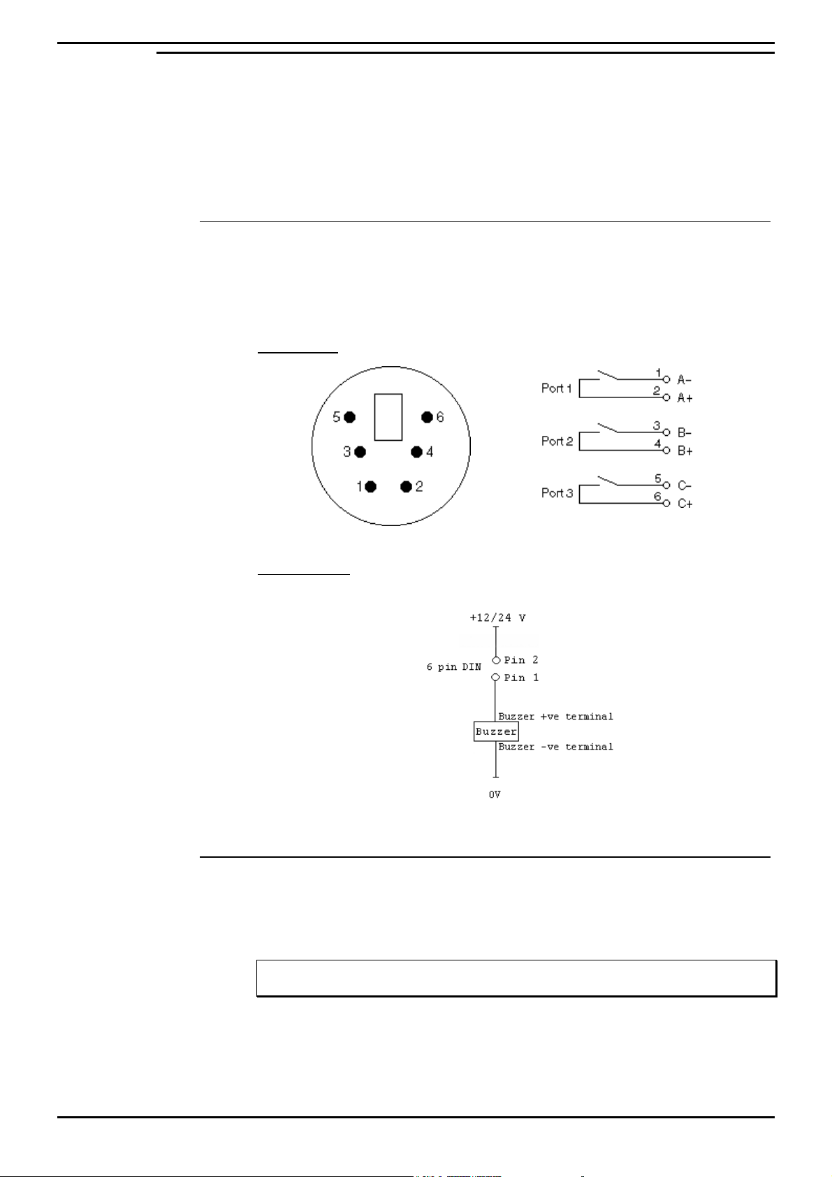
Wallboard Installation and Maintenance INDeX Wallboard 22
Additional Equipment
External Alarm Device for connection to INDeX Wallboard 22 only.
An external alarm device is available to supplement the in-built buzzer. This
interface allows a DC powered device to be attached to a couple of pins provided by
a 6-pin DIN connector, which is mounted on the rear of the display. This 6-pin DIN
port provides the ability to connect the additional device in addition to the internal
buzzer.
Connection Details
The external 6-pin DIN connector is located adjacent to the Mains Power Lead (IEC
Connector). The pins are numbered on the connector from 1-6. Port 1 will replicate
the internal buzzer, and should be used for buzzers. Ports 2 and 3 are not used at
this point.
Socket View
6 Pin Mini-DIN
The overall connection schematic looks like this:
Compatible external devices
All of the devices below are available from the Farnell Electronics Catalogue, and
have been tested by Ferrograph and are recommended as suitable for connection
to the external interface.
Fig. 4
Fig. 5
Note
This external interface has been designed for connection of DC Voltage devices ONLY.
Continuous/Pulsed Single Tone Sounders – 12V & 24V DC
Farnell Reference: FEC143-400
FEC143-402
FEC143-403
INDeX Contact Centre Modules Page 98
Installation & Maintenance 38HBK00001SCM - Issue 11 (05/01)
Page 99
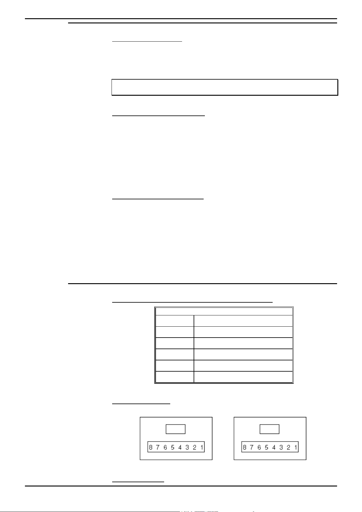
Wallboard Installation and Maintenance INDeX Wallboard 22
Periodic Maintenance and Inspection
Cleaning Display Screen
Time periods between cleaning depend upon local conditions and are at the
discretion of the operator. This routine cleaning can be carried out in the normal
way using a damp and/or dry cloth.
Note: This screen is specially coated to reduce reflections and although this coating is very
durable misuse or incorrect cleaning procedures can damage it.
LED Illumination Test Inspection
The purpose of this test is to ensure no LED fails to illuminate and should be
checked annually.
Remove the left-hand end cheek and carefully slide out the logic control board so
that the dip-switches are accessible. Set switch 8 to ON, inspect the LED display
that will run blocks of Green, Red and Yellow across the display. Look for any LEDs
that fail to illuminate.
Return switch 8 to the OFF position to stop this test.
LED Matrix Scanning Inspection
The purpose of this inspection is to ensure the LED matrix is being scanned
correctly. Remove the left-hand end cheek and carefully slide out the logic control
board so that the dip-switches are accessible.
Set switch 7 to ON, Yellow diagonal stripes will run across the display. Check that
these stripes are straight and that Yellow is the only colour displayed. Having
completed this visual inspection return switch 7 to OFF and ensure that all switch
settings comply with system requirements for baud rate and wallboard network
address number. See Section D for dip-switch details.
Serial Connection & Dip-Switch Details
Wallboard Terminal Box RJ45 Connector Pin Out Details
Pin
2 Signal Ground
3 Sign Rx+ Input
4 Sign Tx+ Output
5 Sign Tx- Output
6 Sign Rx- Input
7–
Pin out Connections
Wallboard x RJ45 Socket Wallboard x+1 RJ45 Socket
Pins from 2 to 7 should be connected identically from all RJ45 boxes to all others.
Dip-Switch Details
INDeX Contact Centre Modules Page 99
Installation & Maintenance 38HBK00001SCM - Issue 11 (05/01)
Page 100

Wallboard Installation and Maintenance INDeX Wallboard 22
Network Address
OFF Position Represents 0
ON Position Represents 1
SW4 SW3 SW2 SW1 ADDRESS
0000 0
0001 1
0010 2
0011 3
0100 4
0101 5
0110 6
0111 7
1000 8
1001 9
1010 10
1011 11
1100 12
1101 13
1110 14
1111 15
Baud Rate
Dip Switch Settings are:
SW5 SW6 DATA BIT/SEC
OFF OFF 19200
ON OFF 9600
OFF ON 2400
ON ON 1200
Ensure the Baud rate is set to 9600.
Test Functions
SW7 SW8 FUNCTION
OFF OFF Normal Running
ON OFF Diagonal Stripe Test
OFF ON Full Screen LED Test
ON ON Information Screen
(Only on power up)
The information screen shows three pages where the following text is displayed.
The dip switches must be set with the display powered down, then switch power on
to achieve information screen.
Yellow Text Software Version
Sign Type
Green Text Network
Number
Red Text Baud
Rate
INDeX Contact Centre Modules Page 100
Installation & Maintenance 38HBK00001SCM - Issue 11 (05/01)
 Loading...