

Page 1

INDeX IPNC Cassette
Administration Manual
38DHB0002UKDD – Issue 7 (22/11/02)
Page 2

Page 2 - Contents
Contents
Introduction.............................................4
Making Your System Secure..............................4
Use of this Manual..............................................4
The IP Networking Cassette Introduction...........5
The IPNC Hardware ........................................... 6
The Boot Process............................................... 7
Installation into the INDeX .....................8
Overview ............................................................8
Modem Set-up.................................................... 8
Software Upgrading and Installation ....9
Introduction.........................................................9
Installing Software Upgrade ...............................9
Installation of a New System............................13
Static IP Addressing ..............................................13
Dynamic IP Addressing .........................................14
Installation Procedure............................................ 15
The Manager Application.....................16
Introduction.......................................................16
Starting the Manager........................................ 17
General Use of the Manager ............................ 19
The Configuration Forms....................................... 20
Operator Profiles ..............................................21
Changing Operator Profile Passwords .................. 21
To Create an Operator Profile ............................... 22
Configuration Files ...........................................23
Opening/Saving Configurations Files Overview .... 24
The File Menu ..................................................25
Open ...................................................................... 25
Close...................................................................... 25
Save....................................................................... 25
Save As ................................................................. 26
Change Working Directory ....................................26
Change Password .................................................26
Preferences | Edit .................................................. 26
Offline .................................................................... 27
Open File ..................................................................... 27
SendConfig .................................................................. 27
RecvConfig .................................................................. 28
Advanced............................................................... 29
Backup/Restore ..................................................... 30
File/Import/Export Directory ......................................... 30
Log Off ......................................................................... 30
Exit............................................................................... 30
Remote Operation .................................................31
The Remote System .................................................... 31
The Off-Site Manager .................................................. 31
Bootp ..................................................................... 31
The Configuration Tree Functions......32
Introduction.......................................................32
The System Configuration Menu......................32
Addressing on the Local Subnet............................ 33
The System Configuration ..................................... 34
The LAN1/2 Tab ....................................................35
The DNS Tab......................................................... 36
The Gatekeeper Tab.............................................. 37
Line Functions..................................................38
ISDN Lines............................................................. 38
Short Codes Tab.................................................... 39
The Voice over IP Tab........................................... 40
Page 2 - Contents INDeX IPNC Cassette Administration Manual
38DHB0002UKDD – Issue 7 (22/11/02)
VPN Lines ..............................................................41
The ShortCode Function .................................. 42
Examples of System Codes ...................................42
The Unit Function.............................................43
Extension Configuration ................................... 43
User Configuration ........................................... 44
The User Tab .........................................................44
The Source Numbers Tab......................................45
The Dial In Tab.......................................................45
Service Configuration.......................................46
The Service Tab.....................................................47
The Service form for WAN and Intranet.................48
The Bandwidth Tab ................................................49
The IP Tab..............................................................50
The AutoConnect Tab ............................................51
The Quota Tab .......................................................51
The Fallback Tab ...................................................52
The PPP Tab..........................................................52
The Dial-In Tab ......................................................54
RAS Configuration ...........................................55
The RAS Tab .........................................................55
The PPP Tab..........................................................55
WAN Configuration ..........................................56
Time Profile Function ....................................... 57
Firewall Configuration ......................................58
The Standard Firewall Tab.....................................58
The Custom Firewall Tab.......................................60
Examples................................................................61
IP Routing ........................................................62
How Do I?..............................................63
Part 1 IP Connectivity....................................... 64
Introduction ............................................................64
Remote Access ......................................................65
Internet Access using ISDN Dial-up Services ..............65
Dial-in Access for PC Modem/ TA with Callback ..........67
Digital Services ......................................................69
IP connectivity DPNSS/QSIG/PRI/BRI .........................69
Home Office / Small Office (With IP Office).................. 75
WAN with Lease Lines ...........................................78
Quick WAN set-up........................................................ 78
Advanced WAN set-up .................................................80
Frame Relay...........................................................83
LAN ........................................................................85
LAN – with VPN ROUTERS .........................................85
LAN –Two INDeX System - Single Site........................87
QoS over WAN between IPNC & 3rd Party Router88
Part 2 Voice Over IP ........................................89
Introduction ............................................................89
Step 1- INDeX environment ...................................90
IPNC channel type .......................................................90
INDeX Net ....................................................................92
INDeX environment for Home Office /Small Office.......92
Configuration................................................................93
Step 2 - Test Index environment............................96
Step 3 - Configure IP Connectivity.........................97
IP Connectivity Options ................................................97
QoS ..............................................................................97
QoS interoperation with 3rd Party routers .....................98
Step 4 - Test IP Connectivity..................................98
Step 5 - Configure VPN Line..................................99
VoIP Gateway Options.................................................99
Step 6 - Test end-to-end Voice and Data ............103
Page 3

Contents - Page 3
Configuring VoIP.................................................. 106
INDeX to INDeX VoIP Trunking ................................. 106
Home Office / Small Office......................................... 108
Appendix A: General Information .....109
Internet Access...............................................109
The Corporate Intranet ........................................ 110
Data Routing........................................................ 112
Security ..........................................................115
Security Implementation - A Dial-In User ............116
Voice-Over-IP................................................. 118
Implementation Considerations ........................... 118
Appendix B: Concepts .......................119
Configuring data routing on the IPNC ............119
Callback ............................................................... 120
IP Routing ............................................................ 121
Dynamic IP parameter allocation......................... 122
Voice Over IP Basics......................................123
Gateway............................................................... 123
Gatekeeper .......................................................... 124
SoftPhone ............................................................ 124
Appendix C: Overview of IP Routing 125
IP Addresses & Subnets ................................125
Domain Name System (DNS) ........................126
Dynamic Host Configuration Protocol (DHCP)126
Address ranges ..............................................127
Boot Protocol (BOOTP)..................................127
Firewall Rules.................................................128
Network Address Translation (NAT)...............129
Appendix D: Use Of The Serial Port .130
Introduction.....................................................130
Erasing the Configuration............................... 130
Erasing/Re-Installing Operational Software ...131
Troubleshooting..............................................132
Appendix E: Cables............................133
DTE Cable...................................................... 133
Pin Connections......................................................... 133
LAN Cable......................................................134
Pin Connections......................................................... 134
LAN Crossover Cable.....................................135
Pin Connections......................................................... 135
V.24/V.28 WAN Cable....................................136
Pin Connections......................................................... 136
X.21 WAN Cable ............................................137
Pin Connections......................................................... 137
V.35 WAN Cable ............................................138
Pin Connections......................................................... 138
Glossary ..............................................139
Index ....................................................143
INDeX IPNC Cassette Administration Manual Contents - Page 3
38DHB0002UKDD – Issue 7 (22/11/02)
Page 4

Page 4 - Making Your System Secure Introduction
Introduction
Making Your System Secure
It is vital to your business that your system is secured. There are different
aspects of security that your System Administrator should consider. This is
particularly important for any system that supports dialled access and Internet
connection. The IP Networking Cassette (IPNC) includes several security
features to help prevent unauthorised access and it is recommended that you
implement them as a priority.
It is your responsibility to provide additional security for your network and
any sensitive information.
It is recommended that the System Administrator take the following steps:
1. Change the system passwords immediately after handover.
See Changing Operator Profile Passwords on page 21.
2. Change the default password for user ‘RemoteManager’.
See Remote Operation on page 31.
3. Ensure that he or she and all users change their passwords on a regular
basis, at least every 90 days.
4. Change all passwords if there is any doubt as to the integrity of the system or
existing passwords.
5. Delete the user profile for members of staff who leave the company.
See User Configuration on page 44 and the details for any data services
which are removed.
6. Implement the Firewall facility
See Firewall Configuration on page 58.
7. Carry out security checks on a regular basis.
It is also important to safeguard all software supplied with the IPNC. The software
CD should be kept in a safe place and you should transfer your most recent
configuration file to suitable media for safekeeping.
See Configuration Files on page 23.
Use of this Manual
This manual covers the installation/upgrading of an Avaya ™ IP Networking
Cassette (IPNC) operating on software Level 3.2 and an INDeX system operating
software Level 10.0+ or higher.
This manual basically consists of four parts as follows:
Part 1: Installation and Software Upgrades
Part 2: The Manager Application, Configuration Tree menus; their contents
and use.
Part 3: A set of worked example in a How do I? section.
Part 4: Appendixes containing General Information/Concepts, an Overview of
IP Routing plus port and cable details.
For installation of IPNCs operating a Level 2.0+, refer to issue 6 of this manual.
This guide is intended for use by installers who are familiar with the INDeX
system and have successfully completed the appropriate INDeX training courses.
Ensure that you have read and understood this Guide before beginning
installation.
Page 4 - Introduction INDeX IPNC Cassette Administration Manual
Making Your System Secure 38DHB0002UKDD – Issue 7 (22/11/02)
Page 5

Introduction The IP Networking Cassette Introduction - Page 5
The IP Networking Cassette Introduction
The INDeX offers the advantages of integrated voice and data communications to
small and medium sized organisations. An IPNC provides a wide range of
facilities and can support many applications, both at a single site and at
dispersed locations. The IPNC provides fast flexible Internet access, implements
e-commerce strategies, Remote Access Solutions and Voice over IP.
The IPNC Voice-over-IP solution can fully utilise all of the available bandwidth,
providing significant line rental savings. The IPNC utilises voice compression
techniques to optimise speech quality against cost and has up to 20 compressed
voice channels (to G.723.1 / G.729a standards).
The IPNC is designed to provide a custom solution that is both easy to use and
easy to manage, with secure data transmissions. Principal features of the
products are:
- Secure Internet access and data services.
- Intranet / wide area capability.
- Dynamic addressing with an integrated DHCP server.
- TCP/IP routing.
- Dynamic bandwidth management for data services.
- Voice-over-IP (VoIP).
- Network Address Translation, for added Internet security and local IP
addressing flexibility.
- Firewall to protect against intrusion from the Internet, the wide area, and by
dial-in access.
- Remote Access Server (RAS) for custom dial-in data services.
- Remotely Manageable.
- Timebands - to restrict access to when, and only when, it is needed and
authorised.
- Encrypted Passwords - to allow access only by authorised users. All data
service activity is password-controlled.
INDeX IPNC Cassette Administration Manual Introduction - Page 5
38DHB0002UKDD – Issue 7 (22/11/02) The IP Networking Cassette Introduction
Page 6

Page 6 - The IPNC Hardware Introduction
The IPNC Hardware
The IP Networking Cassette is available as six variants as follows:
IPNC : Suitable for Internet Access only solutions.
All IPNCs are equipped with a minimum of two 64K B channels,
an X.21/V35/V24 lease line port, one 10BaseT Ethernet port plus
one auto-sensing 10/100BaseT Ethernet port.
IPNC-VC5: An IPNC with a 5 Channel voice compression module. Suitable
for Internet Access or, if used with the LIC-IPNC32 Licence,
remote access from TAs and Routers, and Voice over IP
applications.
IPNC-VC: An IPNC with a 20 Channel voice compression module. Suitable
for Internet Access or, if used with the LIC-IPNC32 Licence,
Remote Access from TAs and Routers, and Voice over IP
applications.
IPNC-M : An IPNC suitable for Internet Access and Remote LAN Access
(includes four V.90 modems).
IPNC-M-VC5: IPNC with four V.90 Modems and a 5 Channel voice
compression module. Suitable for Internet Access or, if used with
the LIC-IPNC32 Licence, Voice over IP applications and Remote
Access from TAs Routers, and Modems.
IPNC-M-VC: An IPNC with four V.90 Modems and a 20 Channel voice
compression module. Suitable for Internet Access or, if used with
the LIC-IPNC32 Licence, Voice over IP applications and Remote
Access from TAs Routers, and Modems.
INDeX Licence Key (LIC-IPNC32)
An optional INDeX Licence Key (LIC-IPNC32) is available to
upgrade from the basic two B channels to the full thirty-two 64K
Channels. Required whenever there is a requirement for more
than two simultaneous calls.
Each IPNC is supplied with a LAN Cable and Administration software on CD (CDIPNC-ADMIN) containing:
– Installation Wizard – for easy initial configuration of system and Internet
parameters.
– Upgrade Wizard – for upgrading operating software.
– The Manager - for configuration/administration of the system and its features.
– The Monitor - to display an on-line, time-stamped log of all call processing
events, for all calls or selectively.
– An electronic manual.
Page 6 - Introduction INDeX IPNC Cassette Administration Manual
The IPNC Hardware 38DHB0002UKDD – Issue 7 (22/11/02)
Page 7
Introduction The Boot Process - Page 7
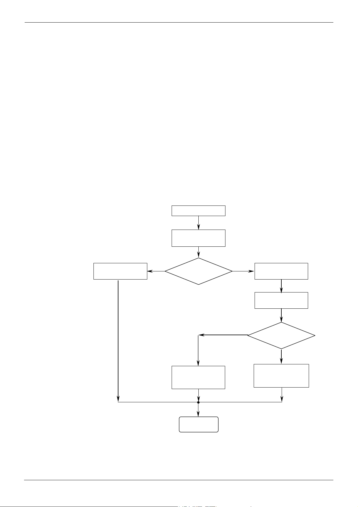
The Boot Process
The boot process is shown in the diagram below. When reset the IPNC first
checks for any directly connected Leased lines. It then checks its configuration,
which is stored in “flash memory”.
When first installed, the IPNC has a default configuration, which includes an IP
address and specifies DHCP server operation. After initial configuration and
subsequent changes, the flash memory may contain a different mode of
operation and a new address.
Note: It is critical that any configuration changes must have been downloaded
to the flash memory in order for them to be implemented at start-up. See
Configuration Files on page 23.
If the IPNC has a non-default configuration and address value, it simply adopts
the defined mode and address.
Alternatively, if the IPNC is in the configuration mode, it first adopts DHCP Client
mode and broadcasts a request for an address. If it receives one, it assumes
another server is present and adopts Client mode. If it does not receive an
address, it adopts the role of a DHCP Server and will provide IP addresses to
clients when they are requested as shown in the following diagram:-
The Start up Process
Adopt Specified
Mode and Address
No
Power Up
Check for:
WAN X.21, V.35
Default
Configuration?
Load Address
Received and
Retain Client Mode
Yes
Yes
Adopt DHCP
Client Mode
Broadcast Request
for IP Address
IP Address
Received?
No
Load Default
Address and Adopt
Server Mode
Ready
INDeX IPNC Cassette Administration Manual Introduction - Page 7
38DHB0002UKDD – Issue 7 (22/11/02) The Boot Process
Page 8

Page 8 - Overview Installation into the INDeX
Installation into the INDeX
Overview
An IPNC (software Level 3.2) only runs on an INDeX system with Level 9.0+ or
higher software. However, software Level 3.2 running on INDeX level 10.0+ are
required to support IPNC tunnelled INDeX DT protocol for VoIP homeworking.
The IPNC installs in much the same way as any other INDeX device cassette.
Refer to the INDeX Installation & Maintenance and INDeX System Programming
Manuals for details. The following is an overview of a typical installation
procedure and should only be used for guidance.
1. Use the INDeX Administration/System/Switch Licence menus to enter the
IPNC licence key (only required when using more than two channels, see
page 6).
– It is important to do this before inserting the IPNC to ensure the correct
number of channels are allocated by the INDeX. If upgrading an IPNC
(see page 9), it may be necessary to de-allocate the cassette before
entering the new licence key and reinserting the cassette.
2. Insert the IPNC cassette. The INDeX will allocate directory numbers to the
IPNC channels automatically. At default on INDeX level 10, the trunk
interface is 'T' type.
Use the INDeX Administration/Linecard Information menu to view and note
the directory numbers.
3. Connect the IPNC cassette to the LAN.
4. The remainder of set-up is done through installing the IPNC software on a
manager PC, see page 8.
Modem Set-up
The modem units within the IPNC cassette do not require any set-up for incoming
calls. They operate using auto-detection of modem traffic on any IPNC channel.
For outgoing calls, the use of the modem port is specified under the Service
Configuration menu (see The PPP Tab on page 52).
Page 8 - Installation into the INDeX INDeX IPNC Cassette Administration Manual
Overview 38DHB0002UKDD – Issue 7 (22/11/02)
Page 9

Software Upgrading and Installation Introduction - Page 9
Software Upgrading and Installation
Introduction
The installation Wizard installs the IPNC Manager application on the
Administration PC.
Notes: 1. The Configuration Wizard is contained on the Administration Software
CD (which can also be accessed by running Setup.exe). The CD will
auto run unless this feature has been disabled on the PC.
2. The IPNC Manager application is common to both INDeX IPNC and
Avaya IP Office systems. However, the IPNC Manager application
must not be installed on a PC being used to administer an Avaya
Alchemy system.
Installing Software Upgrade
The following details the steps necessary to upgrade an IPNC 2.2 to 3.2
software.
To do this, it is necessary to first load IPNC 2.2 (1076) software to update the
IPNC loader firmware to version 1.7, which is required in order to load IPNC 3.2
software.
CAUTION: Before upgrading to 3.2 software, you must make a hard copy of
the existing 2.2 configuration. This is necessary because, once the
3.2 software has been loaded, it is not possible to reload an existing
2.2 configuration file. The existing 2.2 configuration can then be retyped into the 3.2 Manager application.
Notes: 1. In the following, all commands in bold type are case sensitive and
should be entered as specified.
2. In the following, it is assumed that the CD is in Drive D.
Upgrade Steps Explanation
Step 1
Connect a terminal to the IPNC’s DTE maintenance
port (see page 6).
Open HyperTerminal (or similar) to communicate
with the IPNC.
Type at to test the connection.
The IPNC should return, ‘OK’ if the terminal is
correctly configured.
Step 2
Save the current IPNC 2.2 configurations files to a
new folder.
Make a hard copy of the existing 2.2 configurations.
In order to access the DTE port the
HyperTerminal must be configured to operate
as follows:-
38400, 8, N, 1
In case it is necessary to abort the upgrade
and return to the 2.2 build, you will need the
configuration files.
This hard copy will be needed for
re-typing into the new 3.2 Manger application.
INDeX IPNC Cassette Administration Manual Software Upgrading and Installation - Page 9
38DHB0002UKDD – Issue 7 (22/11/02) Introduction
Page 10

Page 10 - Installing Software Upgrade Software Upgrading and Installation
Upgrade Steps Explanation
Step 3
Uninstall the existing IPNC 2.2 Manager software
from the PC.
Install the new IP Office Admin Suite 3.2 from the
Failure to un-install the 2.2 build will result in
software clashes.
The installation procedure is similar to
installing a new system.
CD, see page 13.
Step 4
Open the IPNC Manager from Program
Files\Avaya\IP Office Admin Suite. (Administrator
default password is Administrator.)
From File|Change Working Directory ensure that the
Note:
This may have been set to:
C:\Program Files\Alchemy\Manager by default.
working directory is set as:
C:\Program Files\Avaya\IP Office\Manager.
Step 5
In the directory C:\Program Files\Avaya\IP
Office\Manager rename the file nadrcii.bin file to
nadrciiold.bin.
This is the 3.2(19) software.
The original nadrcii.bin (now called
nadrciiold.bin) file will need to be renamed to
nadrcii.bin to upgrade to 3.2 firmware
described later in Step 13
Use Explorer to copy the nadrcii.bin file from the
D:\bin\2.2(1076) directory on the new CD to the
directory C:\Program Files\Avaya\IP
Office\Manager.
This is the 2.2(1076) software.
Step 6
From the IPNC Manger, open UpgradeWiz
(File|Advanced|Upgrade). Right click in the
UpgradeWiz window and Select Directory as
D:\bin\2.2 (1076). Select the nadrcii.bin file, click
OK. In UpgradeWiz, 2.2 (1076) will appear as
Available. Click Upgrade to load the 2.2 (1076)
firmware image to the IPNC.
Note: It is preferable to use a static IP address from
The IPNC 2.2 (1076) build is only required to
upgrade the IPNC Boot Loader from version
1.3 to 1.7.
Boot Loader 1.7 is required to support IPNC
3.x firmware.
IPNC 2.2 (1076) firmware must not be used
operationally. It is for upgrade purposes
only.
the PC configured to the IPNC subnet.
Step 7
When the IPNC reboots and is operational with
IPNC 2.2(1076) firmware, type the following
command on the DTE maintenance port (see Step
1).
at-debug
This will return the following prompt
<DRC Manager Version 0.1>
When the IPNC is operational the Green
status LED should be ‘on’ and Red status LED
should be ‘off’.
The upgrade, via UpgradeWiz, shows the
rebooting sequence. If the upgrade process
finishes and says it has failed, ignore and
press OK.
Tue 27/8/2002 11:18:51, Hello>
Page 10 - Software Upgrading and Installation INDeX IPNC Cassette Administration Manual
Installing Software Upgrade 38DHB0002UKDD – Issue 7 (22/11/02)
Page 11

Software Upgrading and Installation Installing Software Upgrade - Page 11
Upgrade Steps Explanation
Step 8
At the debug prompt type the following command:
ipoffice
Step 9
If the previous steps have been followed correctly
and the upgrade is successful thus far to loader
version 1076, an output similar to the following will
be shown.
Tue 27/8/2002 11:30:28, Hello>ipoffice
This is irreversible. Continue (Y/N)?
Press Y on the keyboard.
If the previous steps have been followed
correctly and the upgrade to 1076 is
successful the following output will be shown.
New Boot Sector process
Checking new loader code
New loader code checksum =
0x2EABEEAC, (wanted 0x2EABEEAC)
Saving current feature table
Mac address is 00E007005C27
**********************************
ERASING and PROGRAMMING LOADER
**********************************
**********************************
DONE
**********************************
Tue 27/8/2002 11:31:28, Hello>
Step 10
Reboot the IPNC by typing the following command
at the debug prompt.
reboot
e.g. Tue 27/8/2002 11:31:28, Hello>
reboot
Step 11
When the IPNC has finished the boot sequence and
the green LED comes on and the Red LED is off,
unplug the IPNC from the INDeX.
Step 12
In order to confirm the IPNC is running the 1.7
Loader image, plug in the IPNC and press ‘Esc’ on
the keyboard within 3 seconds.
The following output will be shown indicating the
Pressing the ‘Esc’ in this way causes the
IPNC to stop the image load to allow direct
access to the loader mode.
upgrade procedure is successful.
P5 Loader 1.7 (2MB-2xF800 Flash-120nS
SDRAM-10)
CPU Revision 0x0502
To quit this mode and continue at the prompt
sequence type: atf
INDeX IPNC Cassette Administration Manual Software Upgrading and Installation - Page 11
38DHB0002UKDD – Issue 7 (22/11/02) Installing Software Upgrade
Page 12

Page 12 - Installing Software Upgrade Software Upgrading and Installation
Upgrade Steps Explanation
Step 13
Once the IPNC has been restarted load the IPNC
3.x firmware using the Manger UpgradeWize
(File|Advanced|Upgrade).
In step 2, the nadrcii.bin was renamed nadrcii.old.
For the 3.2 version of IPNC firmware this must be
renamed back from nadrcii.old to nadrcii.bin. The
2.2(1076) bin file can be renamed appropriately.
Note:
Loader v1.7 is compatible with IPNC 2.2 or 3.2
software for operational use. If IPNC 3.2 is to
be loaded then the loader must be v1.7.
When the upgrade via the wizard shows the
rebooting sequence.
If the upgrade process finishes and says it has
failed, ignore and press OK.
Step 14
Check the firmware variant by opening the upgrade
wizard again and see the Unit build number (3.2/19)
To prove that upgrade is successful use the
Refresh button on the Upgrade Wizard to
update the display.
Confirm that the version shown in the Version
column is the same as that shown in the
Available column.
Step 15
Restart the IPNC with 3.2 software and ensure that
it is defaulted to factory settings as follows:
Using IPNC Manager:
Open File|Advanced|eraseConfig (factory Default).
Or
When connecting for the first time via the
Manager after defaulting, please check that
the DHCP Server address range is 200 to
LAN 1 and LAN 2.
If these are blank then DHCP will fail.
Using HyperTerminal:
Unplug the IPNC. Plug in the IPNC and press the
'Ecs' key every second until the Loader message
appears.
Enter AT return
Enter AT-X2 return
Enter AT-X3 return
Unplug the IPNC and plug in again.
Page 12 - Software Upgrading and Installation INDeX IPNC Cassette Administration Manual
Installing Software Upgrade 38DHB0002UKDD – Issue 7 (22/11/02)
Page 13
Software Upgrading and Installation Installation of a New System - Page 13
Installation of a New System
At initial start up or reset, the IPNC searches for an IP address from any available
DHCP server. If an IP address is found, the IPNC adopts a DHCP client mode
and accepts the address. Alternatively, an IP address is not found, the default IP
address is loaded and the IPNC adopts DHCP server mode. See The Boot
Process on page 7.
The IPNC may be connected, via a hub, to an existing LAN that uses either static
or dynamic addressing.
It is simpler to ensure that the manager PC is set to automatic IP addressing
(using DHCP) before proceeding. See Dynamic IP Addressing on page 14 and
Addressing on the Local Subnet on page 33.
Static IP Addressing
The following paragraphs detail the configuration requirements for static IP
addressing of the Administration PC which will be used to configure the IPNC.
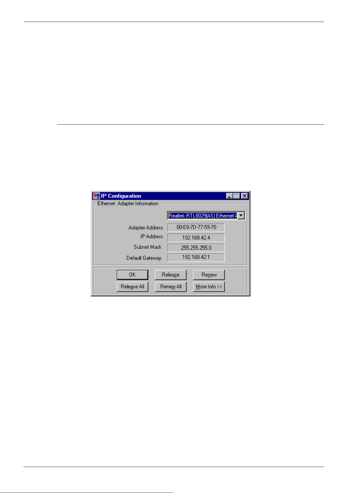
To examine the IP configuration, use Start/Run/winipcfg (Windows 95/98). On
win 2000/NT/XP use the DOS command ipconfig; this command is used to
control IP address allocation/status.
A screen similar to the following example will be displayed:
For an explanation of the IP terms used in this and other menus, see Appendix C:
Overview of IP Routing on page 125.
In the example shown above, the Release and Renew buttons are inactive as
static IP addressing is in force. If the Manager PC is connected to a network with
static addressing, make a note of the IP address as you will need it later during
the configuration procedure.
A PC with static addressing will fail to communicate with the IPNC if it has been
configured for a different network. If your PC fails to communicate with the IPNC
at the beginning of the procedure, check that it is set to automatic addressing
(see page 14).
INDeX IPNC Cassette Administration Manual Software Upgrading and Installation - Page 13
38DHB0002UKDD – Issue 7 (22/11/02) Installation of a New System
Page 14
Page 14 - Installation of a New System Software Upgrading and Installation
Dynamic IP Addressing
The following paragraphs detail the configuration requirements for dynamic IP
addressing of the Administration PC which will be used to configure the IPNC.
To examine the IP configuration, use Start/Run/winipcfg (Windows 95/98). On
win 2000/NT/XP use the DOS command ipconfig; this command is used
To change to DHCP/automatic addressing either:
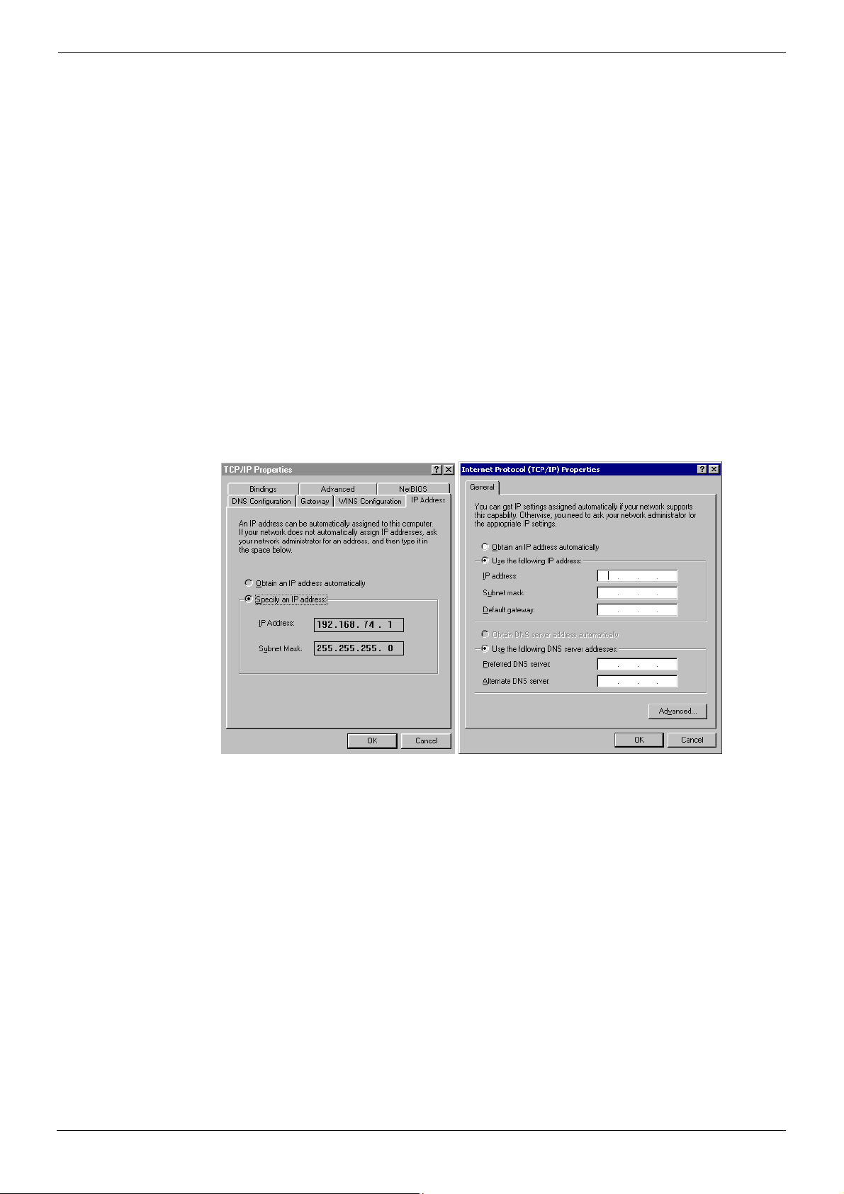
For Windows 95/98: Right-click on the Network Neighbourhood icon or use Start
|Settings |Control Panel and double-click on the Network icon. From the Network
Configuration panel, select the TCP/IP protocol and click on Properties. In the
Properties panel, shown below, click on Obtain IP Address Automatically. It
may then be necessary to re-boot the PC to implement the change.
Or
For Win 2000/NT/XP: Use Start |Settings |Control Panel and double click on the
Network and Dial-up Connections icon. Select the Local Area Connections icon,
right click and select Properties. Highlight the Internet Protocol icon and select
Properties again.
In the Properties panel, shown below, click on Obtain IP Address
Automatically. It may then be necessary to re-boot the PC to implement the
change.
Win 95/98 Win 2000/NT/XP
For a dynamic addressing/DHCP network, the winipcfg Release All and Renew
All buttons can be used to change the adapter’s IP address, (without the need to
re-boot). For Windows NT, at the system prompt, use IPConfig /Release and
IPConfig/Renew instead of Winipcfg.
Page 14 - Software Upgrading and Installation INDeX IPNC Cassette Administration Manual
Installation of a New System 38DHB0002UKDD – Issue 7 (22/11/02)
Page 15
Software Upgrading and Installation Installation of a New System - Page 15
Installation Procedure
The following details the procedures for installation of a new system using the
Configuration Wizard found on the Administration CD. Alternatively, if you are
upgrading the software on an existing IPNC, see page 9.
CAUTION: When upgrading an IPNC to level 3.2, the IPNC must be returned to
it's factory default settings. Hence it is strongly recommended that,
when upgrading a previously configured system (see Installing
Software Upgrade on page 9), a hard copy of the system's
operational configuration settings is made.
Perform the following instructions for installation of a new system:
1. Insert the Admin Software CD (which should self start unless this feature has
been disabled on the PC). Read the Welcome screen and use the Next
button to proceed.
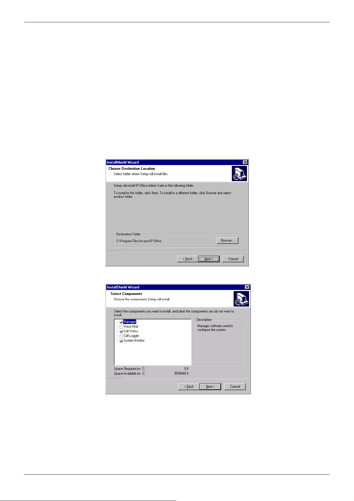
2. The Choose Destination Location menu is displayed. Either accept the
default location, by clicking on Next, or click on Browse, enter your own
location and then click on Next.
3. At the Select Components menu, tick either Manager, Call Status and/or
System Monitor boxes only.
Click Next. The Select Program Folder menu is displayed. Either, click Next
to accept the default, or change the Program Folder and then Click Next.
4. The Setup Status menu runs and when completed click Finish to exit the
Installation Wizard.
INDeX IPNC Cassette Administration Manual Software Upgrading and Installation - Page 15
38DHB0002UKDD – Issue 7 (22/11/02) Installation of a New System
Page 16

Page 16 - Contents
The Manager Application
Introduction
The Manager Application is the configuration and management tool for all
functions of the IPNC. Since the Manager is common to other Avaya products
(e.g. the Alchemy range) some fields are redundant, these will be clearly
identified in subsequent sections.
Each operator has a profile that defines the range of tasks he/she is permitted to
carry out. All profiles are password protected. This Section explains:
– How to start the Manager and obtain a configuration file to edit
– The general use of the Manager
– Defining operator profiles
– Using the Manager’s File menu.
Also included are useful maintenance procedures, such as the remote use of the
Admin PC, enable/disable DCHP, etc.
Note: The Manager Help also runs from CD and can be accessed directly.
Page 16 - Contents INDeX IPNC Cassette Administration Manual
38DHB0002UKDD – Issue 7 (22/11/02)
Page 17
The Manager Application Starting the Manager - Page 17
Starting the Manager
To start the Manager application perform the following:
1. Use Start | Programs | IP Office | Manager.
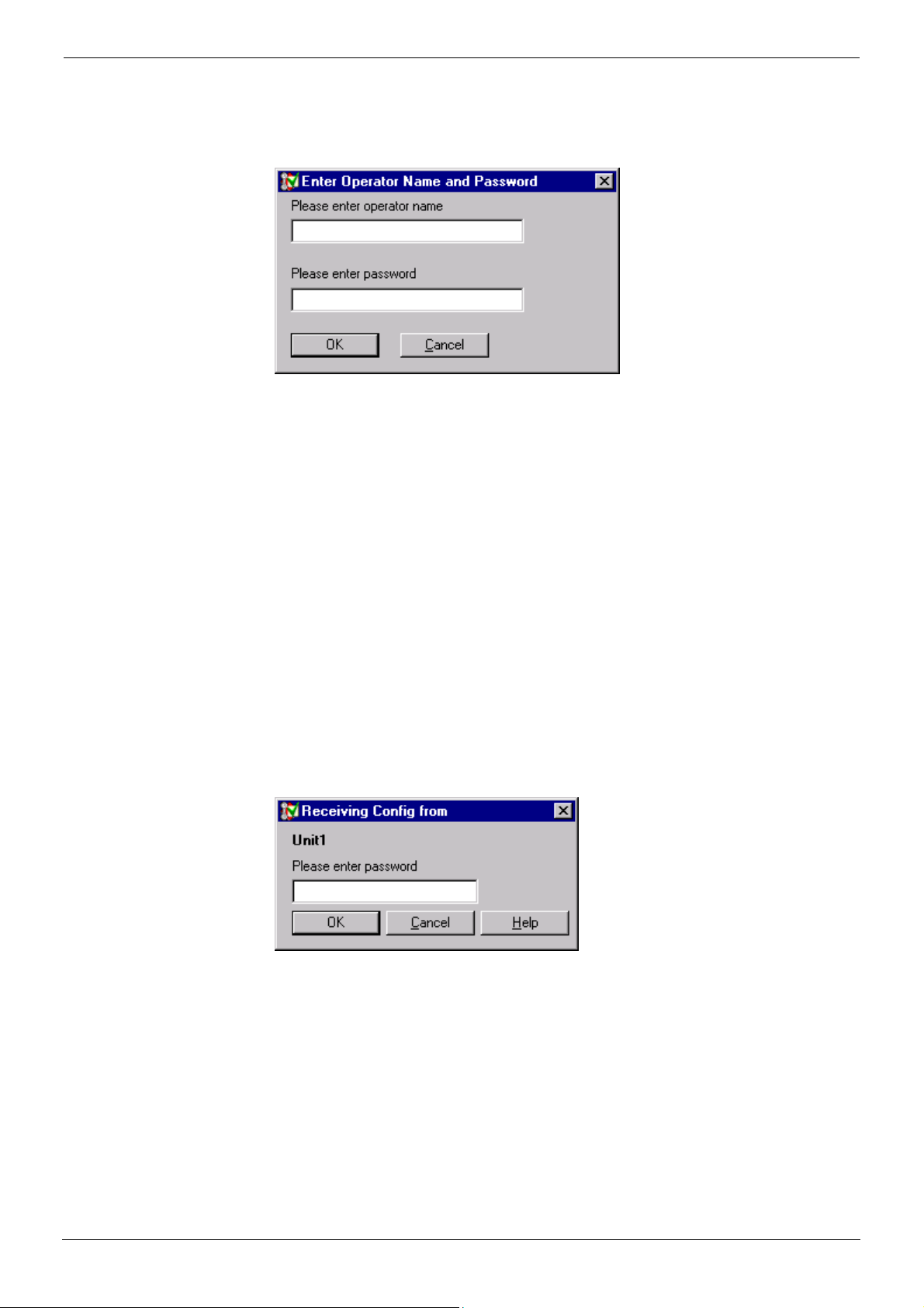
The Operator Name and Password prompts are displayed.
Note for New Installations
A valid operator name and its associated password is required to start the
Manager application. The default conditions are:
Operator name : Administrator Password : Administrator
The Administrator has full access to all configuration menus and is the only
operator who can create, delete and edit operators’ profiles.
When an operator logs on to the Manager and opens a file, only their
permitted functions are displayed.
If you are starting the Manager for the first time, log on as ‘Administrator’. For
security reasons, you must alter the password, and ideally create new
profiles (see Changing Operator Profile Passwords on page 21).
2. Enter the operator name and password, and click on OK.
The Manager is then opened. Use the File menu to open a configuration file
for editing or viewing.
There are two ways of doing this:
3. File/Open (or click on the File icon in the task bar)
This will retrieve the currently-active configuration file from the IPNC once
the password has been entered, by default ‘password’. If you do not receive
this menu, see Installation of a New System on page 13.
Proceed from step 4.
4. File/Offline/Open File
Permits changes to be made to a non-operational file.
Proceed from next step.
Configuration Files on page 23 gives more details about the File menu.
INDeX IPNC Cassette Administration Manual The Manager Application - Page 17
38DHB0002UKDD – Issue 7 (22/11/02) Starting the Manager
Page 18
Page 18 - Starting the Manager The Manager Application
5. If you have just installed a new IPNC, you must first extract the configuration
file from the system to transfer it to the Manager folder, as follows:
a) File | Offline | RecvConfig (the default file name is shown with the
extension .cfg.)
b) Enter the local access password (see Changing Operator Profile
Passwords on page 21 )
c) Either, click on the file icon or use File | Offline | Open File, to open the
required file.
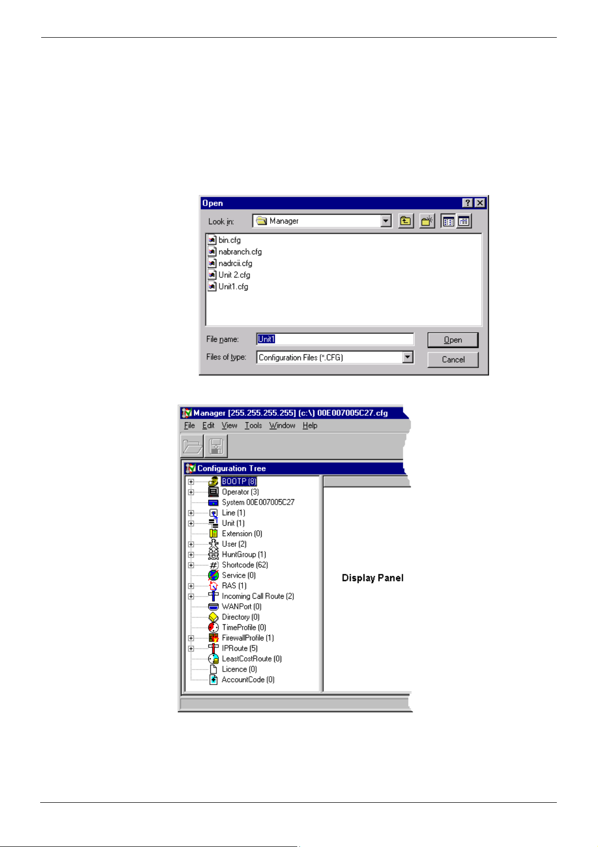
Alternativilty, if changes are to be made off-line, select File | Offline |
Open | File. The Manager then lists the configuration files (with the
extension .cfg). Select the required file and click Open.
6. The Configuration Tree for the file is then displayed as shown below.
Each of the “branches” represents a different Manager function. In the
example shown, the Administrator has logged on and all functions are
displayed. By clicking on a function icon a summery list for that function is
shown in the Display Panel.
Page 18 - The Manager Application INDeX IPNC Cassette Administration Manual
Starting the Manager 38DHB0002UKDD – Issue 7 (22/11/02)
Page 19
The Manager Application General Use of the Manager - Page 19
General Use of the Manager
The list of items in the Manager's Configuration Tree corresponds to the access
rights of the operator who is currently logged on, i.e. whose name and password
has been entered.
CAUTION: Operators should always log off at the end of a session, to prevent
unauthorised use of the system (see Configuration Files on page
23).
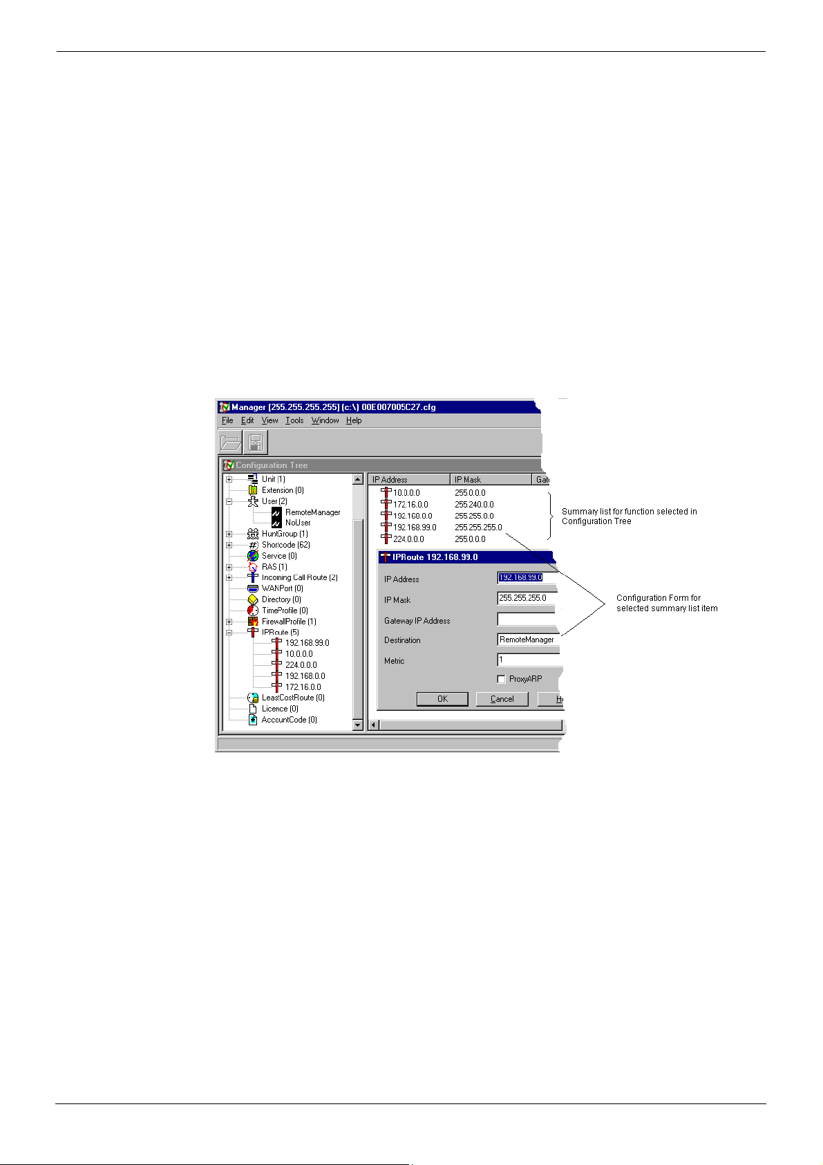
In the example of the Configuration Tree shown below, the operator has full
access rights. Clicking on any one of the items in the Configuration Tree
produces the summary list for that function in the Display Panel.
To edit an item in the summary list, highlight the item's icon and right click the
mouse button. Select Edit from the menu (double-clicking on an item will also
display the menu). The Configuration Form for that item will be displayed (see
The Configuration Forms on page 20). In the example shown, Edit has been
selected to review/change the definition of the IP route for 192.168.0.0 (Remote
Manager).
If a Configuration Tree function contains no entries, i.e., there is no summary list,
click the right mouse button in any part of the Display Panel to obtain the toolbox.
Select New to create a new item.
The Display Panel has scroll bars so that the selected summary list can be
viewed in full. Also, by clicking on the name in the sort bar, the display order is
changed (this is a toggle function).
INDeX IPNC Cassette Administration Manual The Manager Application - Page 19
38DHB0002UKDD – Issue 7 (22/11/02) General Use of the Manager
Page 20

Page 20 - General Use of the Manager The Manager Application
The Configuration Forms
For any item in a function's summary list (see General Use of the Manager on
page 19) configuration values are specified by completing forms. There may be
one or more forms to complete, depending on the function concerned.
A Configuration Form consists of a series of fields in which the correct value(s)
must be entered. Click on a field to enter a value into it. Use the mouse or the tab
key to move from field to field.
The example above shows a User Configuration Form (also see page 44). In this
case, several forms are needed to make a complete user profile. Click on the
tabs to move through the ones you need to complete or change and enter the
necessary details. Click on OK when you have completed the last one. The
changes you have made are then reflected in the summary list.
When a configuration has been changed it must be saved and sent to the IPNC
before it is implemented (see Configuration Files on page 23).
Page 20 - The Manager Application INDeX IPNC Cassette Administration Manual
General Use of the Manager 38DHB0002UKDD – Issue 7 (22/11/02)
Page 21
The Manager Application Operator Profiles - Page 21
Operator Profiles
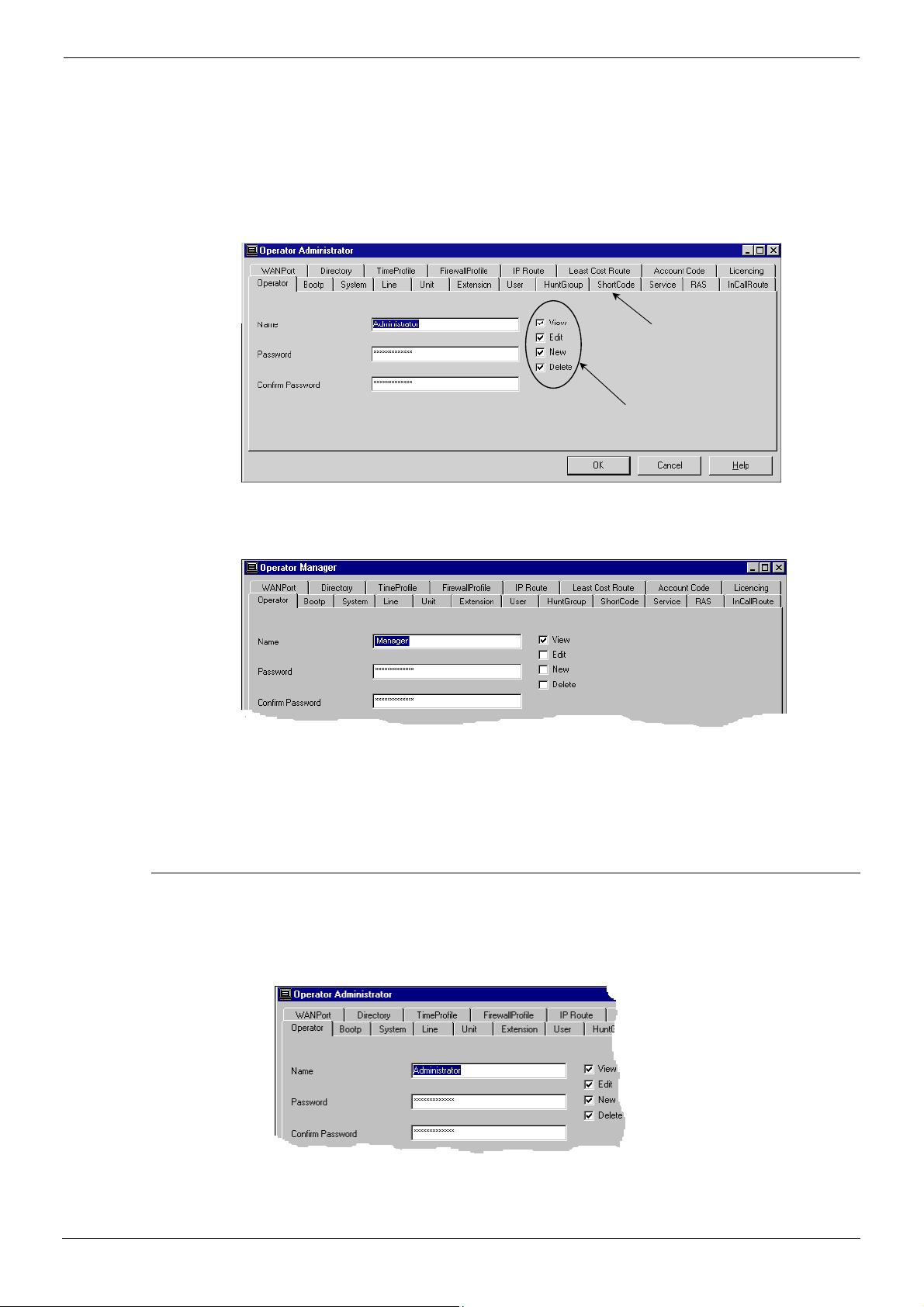
In order to safeguard the security of the system, it is strongly recommended that
the Administrator creates a suitable set of operator profiles that are granted only
the access rights they need. In the default configuration, only the Administrator
can create or alter operators. Hence you must change the Administrator’s
password, but do not make changes to the profile unless you are sure you have
created another with full rights. The default Administrator's profile is shown
below:-
Function Tabs
Operator Rights
The default profiles are for Administrator, Operator and Manager. The latter two
only have the right to View and not to Edit, create New or Delete a profile as
shown below:
The functions tabs, across the top of each profile menu, reflect the functions
listed in the Configuration Tree. However, there are some tabs (functions) that
are not pertinent to IPNC. This is because the Manager application is common to
both the IPNC and the IP Office platform. It is recommended that, when creating
new operator profiles, you delete unnecessary tabs (see page 22 for details), e.g.
Incoming Call Route.
Changing Operator Profile Passwords
Passwords can be changed locally, at the Admin PC, without the need to re-boot
the IPNC. To change the password:
1. Log on with the existing operator name and password, and select Change
Password from the File menu:
2. Click in the Password box and enter the new password.
3. Click in the Confirm Password box and enter it again.
4. Click on OK.
INDeX IPNC Cassette Administration Manual The Manager Application - Page 21
38DHB0002UKDD – Issue 7 (22/11/02) Operator Profiles
Page 22

Page 22 - Operator Profiles The Manager Application
To Create an Operator Profile
1. Log on with operator name and password Administrator (the default name
and password which must be changed at the ealiest opportunity (see
Changing Operator Profile Passwords on page 21).
2. In the Configuration Tree, click on Operator and then right click in the
Display panel and select New from the menu. The following blank profile is
displayed:
3. Click the Operator tab, enter the operator’s name and a new password.
Repeat the new password in the Confirmation box.
4. Tick the boxes according to the rights the new operator is to have. E.g. if only
View is ticked, then this new operator is not allowed to make changes to any
profiles.
5. Move through the other tab functions (the operator’s rights are in the boxes
on the left and the facilities that they apply to are on the right) and select the
appropriate rights.
6. There are some tabs (functions) that are not pertinent to IPNC. This is
because the Manager application is common to both the IPNC and the IP
Office platform. It is recommended that, when creating new operator profiles,
you delete the following unnecessary tabs.
Directory/Least Cost Route/Account Code/Licencing/
Extension/HuntGroup//InCallRoute.
To delete a fuctional tab from view, ensure that the View box is not ticked.
Hence, when you log off and then log on* again with this operator profile,
these functional tabs will not be displayed.
* Use File | Offline | Open File and then acces the new .cfg file from Avay/IP
Office/Manager when logging on again.
7. Press OK when the profile set up is complete.
8. Use File | Log Off to close the configuration file.
Notes: 1. Ensure that the operator knows his or her password and
appreciates the need to keep it secret.
2. A View-only operator can save changes to the configuration file
locally (at the Admin PC) but cannot send a configuration to the
system. An “Access Denied” message is displayed if an
unauthorised attempt is made.
3. Do not leave the Admin PC unattended whilst logged on -
especially if you are an administrator.
9. Always use File | Offline | Send Config to implement changes to operator
profiles. If a new operator is created “offline”, they can log on immediately,
but access restrictions are not in place until Send Config is used to reboot
the IPNC and hence implement the changes (see page 27).
Page 22 - The Manager Application INDeX IPNC Cassette Administration Manual
Operator Profiles 38DHB0002UKDD – Issue 7 (22/11/02)
Page 23
The Manager Application Configuration Files - Page 23
Configuration Files
The operational configuration files (with the extension .cfg) for the IPNC are
stored:
- On the Admin PC in the Manager folder
- In the IPNC's Non-Volatile flash memory
- As the active file in the IPNC's Operational memory.
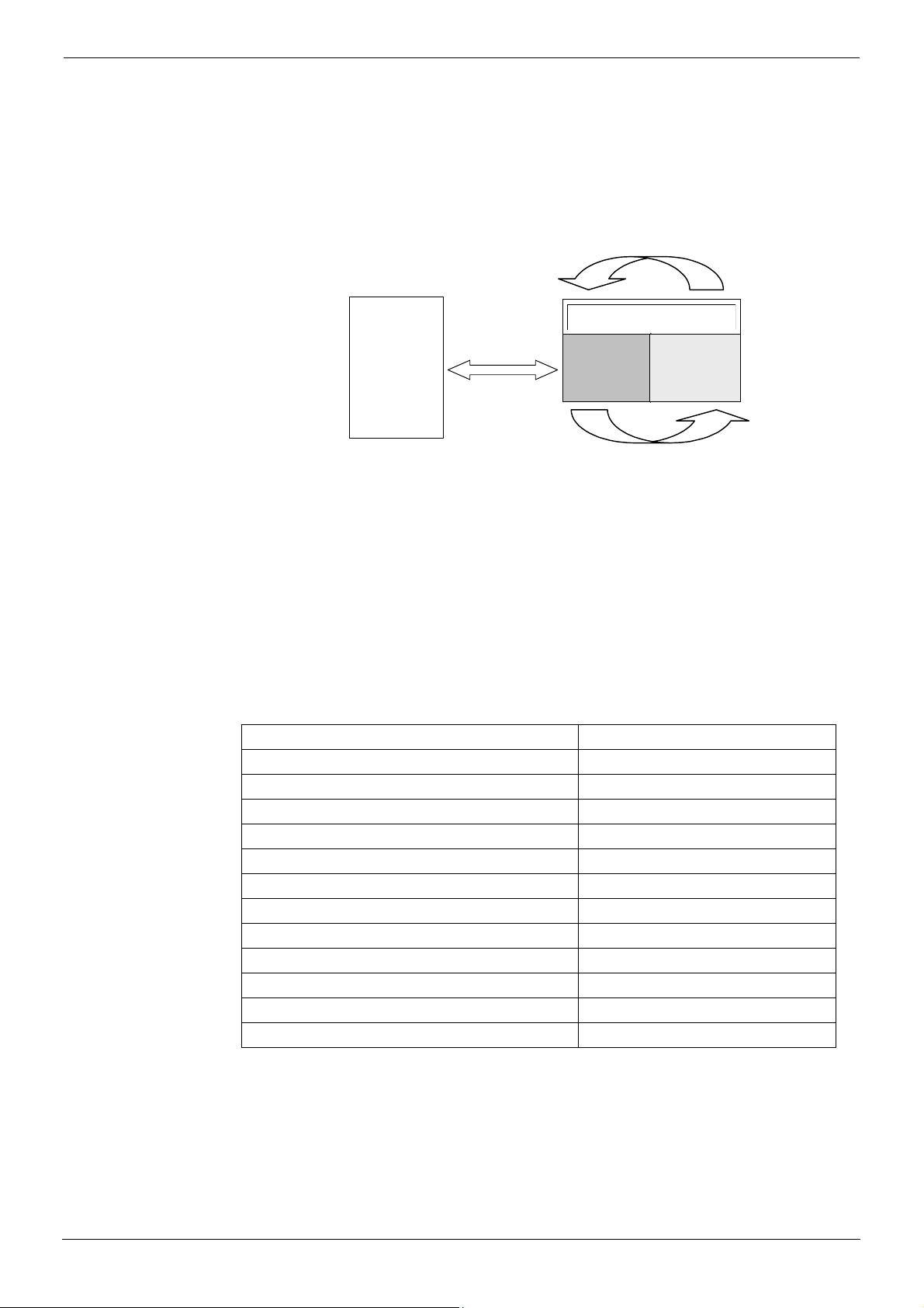
For management of the .cfg files, the IPNC can be viewed as having two memory
areas as follows:
Update
Admin
PC
Manager
Folder
.cfg Files
IPNC Memory
Flash
(NV)
Reboot
Operational
(active)
The IPNC Operational memory contains the active .cfg file. This active file can
be updated by the IPNC itself (with changes made by users, softphones, etc.).
The IPNC updates it's flash memory in two ways:
1. At midnight, provided that the IPNC is idle.
2. When an Immediate or When Free reboot is requested on a Save or
SendConfig instruction from the Manager (see pages 25 and 27).
Most functions, within the .cfg files, that are sent from the PC to the IPNC's flash
memory only become active when the IPNC is re-booted. However, when the
Merge option is used, some become immediately operational. These are shown
in the following table:
Configuration Tree Functions Mergeable
System No
Line No
Unit No
User Partial
Shortcodes Yes
Service Yes
RAS No
WAN Port No
Time Profile No
Firewall No
IP Route Yes
Least Cost Route Yes
INDeX IPNC Cassette Administration Manual The Manager Application - Page 23
38DHB0002UKDD – Issue 7 (22/11/02) Configuration Files
Page 24

Page 24 - Configuration Files The Manager Application
A
Opening/Saving Configurations Files Overview
Configuration files can be opened in different ways as follows:
• Retrieve the current .cfg file from the IPNC's flash memory and open it in
the Manager application. The Configuration Tree for the current .cfg file will
be displayed (see page 25). This file can then be edited but will not become
fully operational until the IPNC is rebooted (see page 25).
• Receive the current .cfg file from the IPNC's flash memory and store it in
the Manager application. The Configuration Tree for the current .cfg file will
not be displayed (see page 27) until the file is Opened (see page 27). When
the file is opened it can be edited but will not become fully operational until
the IPNC is rebooted (see page 25).
• Select and open any of the .cfg files stored within the Manager application.
The Configuration Tree for the select .cfg file will be displayed (see page 27).
This file can then be edited but will not become fully operational until the
IPNC is rebooted (see page 25).
Configuration files that have been created/edited can be saved in different ways
as follows:
A .cfg file that has been created or edited can be
SAVE AS
dmin PC
Manager
Folder
SAVE
Reboot Options
Memory
Send Config
IPNC
Flash
• The Save As option will only save the .cfg file in the Manager folder on the
Admin PC and will not become operation until sent to the IPNC and the IPNC
is rebooted (see page 27).
• The Save option will store the .cfg file in both the IPNC's flash memory and
the Manager folder on the Admin PC. This file will not become fully
operational until the IPNC is rebooted. You are then given options as to
when you wish to reboot (see page 25).
• The Send Config option will store the .cfg file in both the IPNC's flash
memory and the Manager folder on the Admin PC. This file will not become
fully operational until the IPNC is rebooted. You are then given options as to
when you wish to reboot (see page 27)
Note: The Save option is useful for retaining configuration files which are in the
process of being changed.
If substantial changes have been made to a configuration file, it is
advisable to save the existing configuration under a different name, as a
fallback (use File | Save As). A back-up should also be made of the
current configuration, to a suitable archive medium, and stored in a safe
place.
Page 24 - The Manager Application INDeX IPNC Cassette Administration Manual
Configuration Files 38DHB0002UKDD – Issue 7 (22/11/02)
Page 25
The Manager Application The File Menu - Page 25
The File Menu
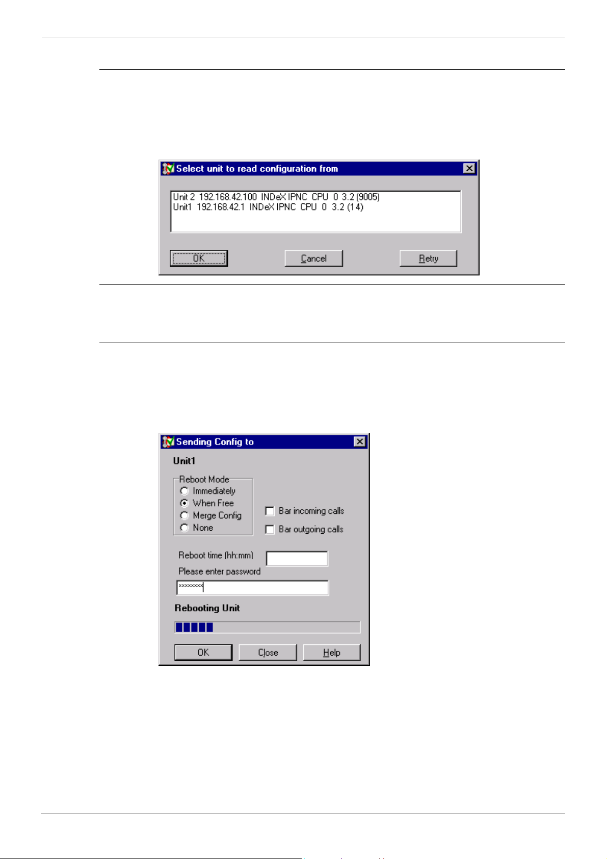
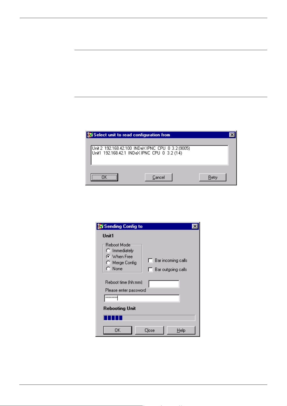
Open
This option (alternatively, you can use the file icon) extracts the currently
operational configuration file(s) from the IPNC's flash memory (see page 23). If
there are multiple IPNCs, then the window shown below is displayed. Select the
required IPNC and then click OK. In all cases you are then requested to enter the
local access password.
Close
This closes the current configuration file. If not already saved, you will be asked
to save the file (see Save and Save As below).
Save
This option (alternatively, you can use the disk icon) saves an open configuration.
When working locally, the file is saved in both the Managers working directory
(see Change Working Directory) and in the IPNC. (If you are still using the
default passwords, you will receive a warning.) When Save is selected locally,
you are asked when you wish to reboot as follows:
The new .cfg file is activated only when the IPNC has been re-booted. You can
choose to re-boot Immediately, which may disrupt service, When Free, or by
Merging Config. Merging is only available for certain parameters and avoids the
need to reboot (see page 23).
Note: The options to reboot the IPNC are also given when you send an edited
.cfg file to the IPNC (see File | Offline | Send Config on page 27).
INDeX IPNC Cassette Administration Manual The Manager Application - Page 25
38DHB0002UKDD – Issue 7 (22/11/02) The File Menu
Page 26
Page 26 - The File Menu The Manager Application
Save As
This option allows you to name and save a file (with a .cfg extension). When
working locally, the file is saved to both in the working directory (see Change
Working Directory) and in the IPNC. (If you are still using the default passwords,
you will receive a warning.) When Save As is selected locally, you are asked
when you wish to reboot (as show above in Save).
When Save As is selected offline, the edited file is only saved to the working
directory of the Manager on the Administration PC. Save As does not send the
file to the IPNC for implementation until the IPNC is rebooted (see File | Offline |
Send Config on page 27).
Change Working Directory
This option allows you to change the working directory from the default
C:\Program Files\Avaya\IP Office\Manager by browsing through your folders in
the usual way.
Change Password
This allows the operator who is currently logged on to change their password as
described in the Changing Operator Profile Passwords on page 21.
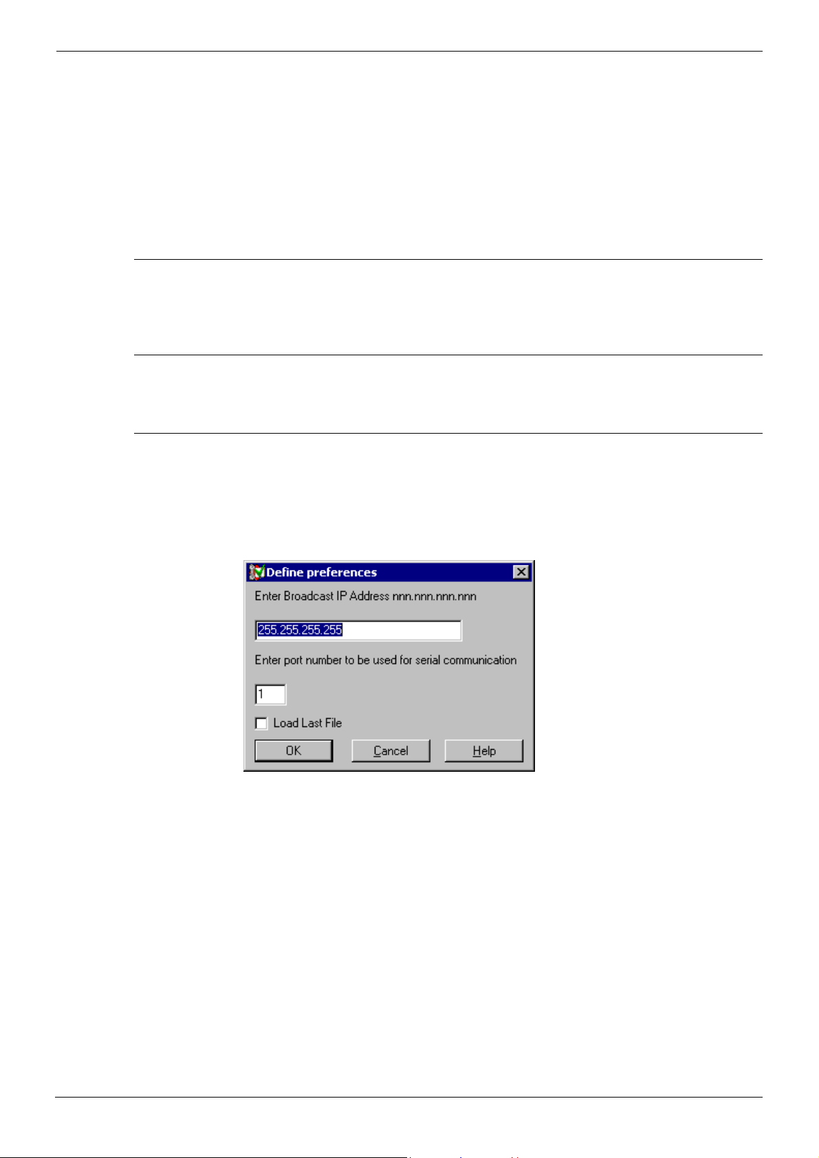
Preferences | Edit
This option allows you to specify:
– A specific IP Address can be specified for remote access to a customers’
sites or left as the Default 255.255.255.255 for local access
– The serial comms port number (Default 1) of the Admin PC.
Page 26 - The Manager Application INDeX IPNC Cassette Administration Manual
The File Menu 38DHB0002UKDD – Issue 7 (22/11/02)
Page 27
The Manager Application The File Menu - Page 27
Offline
This produces three further options that can be used to edit and save a
configuration file that has previously been extracted from the IPNC. Used when
configuration is to be carried out off line:
Open File
This opens a configuration file menu held in the Manager folder of your PC.
When Open File is clicked, use Avay/IP Office/Manager and select, from the list
of .cfg file in the Manager folder, the required configuration file and click on Open
(also see page 25).
SendConfig
1. Where multiple INPCs are in use, your IPNC’s identity is displayed in the
“Who Is” window. Select the required IPNC and then click OK. The Send
Config to screen is displayed (see the next step).
2. Where a single IPNC is in use, the Send Config to screen is then displayed.
The new .cfg file is activated only when the IPNC has been re-booted. You
can choose to re-boot Immediately, which may disrupt service, When Free,
or by Merging Config. Merging is only available for certain parameters and
avoids the need to reboot (see page 23).
Enter the password and click OK.
Note: The View menu TFTP log gives a list of all transactions when
sending a new configuration file or rebooting and can be used to
monitor the process.
INDeX IPNC Cassette Administration Manual The Manager Application - Page 27
38DHB0002UKDD – Issue 7 (22/11/02) The File Menu
Page 28

Page 28 - The File Menu The Manager Application
RecvConfig
This option extracts the currently active configuration file from the IPNC’s flash
memory and sends it to the Manager's working directory on your PC. This
guarantees that you have the current file to work on.
1. Where multiple INPCs are in use, the “Who Is” Screen (see SendConf
above) is displayed first. Highlight the required IPNC, click on OK and
proceed from step 2.
2. You are prompted to confirm or change the target filename.
3. Click OK and at the “Continue?” message click Yes.
4. Enter the passcode, click OK and the file is transferred.
5. Use File | Offline | Open File (see above) to display the configuration.
Page 28 - The Manager Application INDeX IPNC Cassette Administration Manual
The File Menu 38DHB0002UKDD – Issue 7 (22/11/02)
Page 29

The Manager Application The File Menu - Page 29
Advanced
Selecting this produces three options:
Erase Config
This restores the configuration in the units flash memory to the factory default
and should only be used under the direction of an INDeX Business Partner.
Selecting this option produces the “Who Is” window followed by a request to enter
the local access password. The erase request is then sent and a confirmation
message appears at the bottom of the screen.
Note: Always make a copy of your current configuration file to a back-up folder
on the Admin PC, as well as making a separately-stored archive, to allow
a quick recovery - see Backup/Restore below.
Restoring the default configuration also restores default passwords - the local
access default is “password” and the remote access default is “thepword” as
configured against the RemoteManager user.
If, for some reason, LAN connections are lost, the serial port can be used for this
procedure as described in Appendix 1.
Reboot
This option produces the Reboot windows described in SendConfig on page 27.
In normal operating circumstances it should not be necessary to reboot your
system and this should only be carried out on the advice of an INDeX Business
Partner.
Upgrade
CAUTION: This option is only used to load new versions of software above
Level 3.2. To upgrade from 2.2 to 3.2, only use the proceedure
listed in Software Upgrading and Installation on page 9.
Software upgrades are available from the Avaya web site
(http://www.avaya.com
The new files have .bin extensions. Upgrades can only be loaded from an Admin
PC connected to the local subnet, i.e., not by remote access.
Selecting this option produces theUpgradeWiz which, in this case, lists all the
configured units associated with your IPNC. Select the one you wish to upgrade.
When the password window is displayed, enter the local access password and
check that the file shown is correct. Use Browse to locate another if necessary.
).
INDeX IPNC Cassette Administration Manual The Manager Application - Page 29
38DHB0002UKDD – Issue 7 (22/11/02) The File Menu
Page 30

Page 30 - The File Menu The Manager Application
Backup/Restore
This option contains two choices:
Backup
This allows you to create a back-up of a configuration ( .cfg and.bin files) to a
selected directory. Note that there is no confirmation when the process is
complete.
Important Note: Users should always keep a back-up copy of the current
configuration in a safe place, in accordance with their local disaster recovery
procedures - also keep a back-up in another directory on the Admin PC for a
quick re-start, if necessary. Before making substantial changes to an existing
configuration, it is good practice to check that there is a working copy of the
existing configuration as a fallback. Backup copies should be checked routinely to
ensure that the files are readable.
Restore
This allows you to select the directory in which your backup files are held (the
files are not listed when the directory is selected - use Explorer or similar to
check) and copy them to the current working directory.
File/Import/Export Directory
This menu is not used by the IPNC.
Log Off
This logs off the present operator, closes the currently open configuration file,
and produces the Password entry window so that another operator can log on.
You should always log off when you have completed your Manager session or if
you leave the Admin PC unattended.
Exit
This closes the Manager application.
Page 30 - The Manager Application INDeX IPNC Cassette Administration Manual
The File Menu 38DHB0002UKDD – Issue 7 (22/11/02)
Page 31

The Manager Application The File Menu - Page 31
Remote Operation
The Manager can be used to remotely configure multiple sites from a central
location. This facility is a valuable engineering tool for off-site support and
maintenance, enabling the configuration to be received, edited and sent back.
The INDeX environment must also be configured. By default, the IPNC is
configured with a remote manager dial in facility. It is necessary to set up the offsite Admin PC to gain access to the remote system.
The Remote System
The default settings are shown in the table below. If any of these have been
changed from the defaults, it is necessary to know the changes made and to
change the settings at the off-site Manager PC accordingly.
CAUTION: The customer’s password and default IP Address should always be
changed from the default value to prevent illegal access.
Default Dial In Access Settings
Profile Field Value
User Name RemoteManager
Password thepword
Dial In On Ticked
RAS Name DialIn
IP Route IP Address 192.168.99.0
IP Mask 255.255.255.0
Destination RemoteManager
Bootp
The Off-Site Manager
To gain access to your remote system it is necessary to have a method for
dialling into the system. Typically this will be a PC/IPNC system configured as
follows:
1. Create a Service on the local IPNC with the following values:
– Name - a suitable exclusive name for the customer
– Account Name – RemoteManager
– Password – thepword
– Telephone Number - the customer’s number
– Save configuration and upload to IPNC.
2. Use File | Preferences to enter the address of the remote system, i.e.
192.168.42.1
3. Proceed to configure the remote system as if locally connected.
The first item in the Configuration tree is Bootp, which is normally only used to
recover faulty unit (see Boot Protocol (BOOTP) on page 127). The Manager
application acts as a Bootp server and is used to reload the operational software
to the IPNC's flash memory.
INDeX IPNC Cassette Administration Manual The Manager Application - Page 31
38DHB0002UKDD – Issue 7 (22/11/02) The File Menu
Page 32

Page 32 - Introduction The Configuration Tree Functions
The Configuration Tree Functions
Introduction
This Section describes each of the Configuration Tree functions in turn,
explaining the meaning and purpose of all of the fields in the function definition. A
full Configuration Tree will be similar to the following:
Before carrying out changes to a configuration file, be sure to take a back-up.
After completing the changes, remember to download them to your system’s
flash memory. See The Manager Application on page 16 for instructions.
Certain options can be changed and merged into the active configuration file (see
page 23). This avoids the need to reboot the system after each edit. The
following modifications can be merged:
– User : Edit.
– IPRoute : Edit/New/Delete.
– Short Code : Edit/New/Delete.
The System Configuration Menu
The System Configuration menu is used to specify various system parameters,
including:
– System passwords
– IP address information for the IPNC.
It should seldom be necessary to alter the System function values. Firstly, they
are set up at installation by means of the Configuration Manager (see Software
Upgrading and Installation on page 9). Secondly, they are concerned with basic
aspects of the IPNC, such as network type and operation modes that are unlikely
to change. However, you are strongly advised to change the system
passwords.
Note: After editing the System Configuration it is advisable to reboot the IPNC
(changes to the IP address are not effective until after a reboot – see
pages 25 and 27).
Page 32 - The Configuration Tree Functions INDeX IPNC Cassette Administration Manual
Introduction 38DHB0002UKDD – Issue 7 (22/11/02)
Page 33

The Configuration Tree Functions The System Configuration Menu - Page 33
Addressing on the Local Subnet
Before completing the System Configuration menu, the operation of the local
subnet must be considered. This may consist entirely of the devices connected to
the IPNC via a hub, with the IPNC handling all addressing as a Dynamic Host
Configuration Protocol (DHCP ) server. In this case, the configuration is minimal.
In other cases, the IPNC may be connected to an external hub or router and
hence is part of a larger network that may use either dynamic or static
addressing.
CAUTION: It is critical to set up all IP addresses correctly to avoid contention.
A DHCP server assigns IP addresses to clients automatically as they boot up on
a TCP/IP network. In default, when started, the IPNC sends a request for a
DHCP address to the local network. If none is received, the IPNC assumes the
role of a DHCP server and manages all addressing for both LAN devices and
dial-in users. When operating as a DHCP server the IPNC uses it's own address
as the starting address from which it will allocate new addresses to registering
devices. See DHCP mode selection in The LAN1/2 Tab on page 35. If the IPNC
is configured as part of an existing subnet that already uses another DHCP
server, the mode can be set to Client, in order to leave control of the addressing
with the existing server.
Note: On start up, the IPNC automatically becomes a client if it receives an
address, e.g. if the IPNC finds a DHCP server already present on the
network.
The DHCP mode can be also set to Dial In. In this mode, the IPNC manages
DHCP addressing for users with dialled access whilst the existing server
manages addressing on the subnet. Addresses are allocated to dial-in users as
they log on in the usual way, but the maximum number of addresses allowed
must be specified.
WARNINGS
1. IP addresses must not be in a range used by other DHCP servers.
2. In order for the IPNC's DHCP detection status to operate correctly,
the IPNC must be connected to the LAN BEFORE being powered up
(inserted into the INDeX). If this is not done there is the potential of
having TWO DHCPs on the same LAN!
If the lLocal network uses static IP addressing, DHCP must be either set to Dial
In or Disabled. In this case, the system must be given an IP address within the
local subnet range and not in use elsewhere on the network. The addresses for
dial-in users follow in sequence from the IPNC’s allocated address. For example,
if the current subnet address range ends at 123.234.21.10:
– 123.234.21.11 - Is the address of the IPNC
– 123.234.21.12 - Is the first address given to a dial-in user
– 123.234.21.13 - Is the second address given to a dial-in user, and so on.
INDeX IPNC Cassette Administration Manual The Configuration Tree Functions - Page 33
38DHB0002UKDD – Issue 7 (22/11/02) The System Configuration Menu
Page 34

Page 34 - The System Configuration Menu The Configuration Tree Functions
The System Configuration
After editing the System Configuration it is advisable to reboot the IPNC
(changes to the IP address are not effective until after a reboot – see pages 25
and 27).
Note: The Voicemail, Telephony and LDAP tabs are currently not used by
IPNC (reserved for use by IP Office).
Name: A name, for reference only, given to the system, such as a company
name or location.
Password: The password required to enable you to send/receive configurations
to/from the IPNC, to carry out upgrades and to re-boot the unit. The default value
is password. You are strongly advised to change this password.
Monitor Password: This is the password that controls access to the Monitor
application (if installed). If the field is left blank, the password defaults to the
system password above. You are strongly advised to change this password.
Locale: This option sets (automatically from PC setttings) country variations, e.g.
UK = eng, Netherlands = nld, Germany = deu
Time Offset (hours): By default the main unit will receive it's time from the PC
running the Manager application. However, the unit can also synchronise it’s time
to an external timeserver. External time servers provide time in GMT. Thus this
value must be set to the number of hours that your site is ahead or behind
(negative) GMT.
Page 34 - The Configuration Tree Functions INDeX IPNC Cassette Administration Manual
The System Configuration Menu 38DHB0002UKDD – Issue 7 (22/11/02)
Page 35

The Configuration Tree Functions The System Configuration Menu - Page 35
The LAN1/2 Tab
IP Address: The IP address of the IPNC. For static addressing (DHCP disabled),
this is the actual address. For dynamic addressing, this is the start address from
which the client address sequence starts. For DHCP server mode any legitimate
IP address can be entered. You can accept the default or you may wish to
change it. For DHCP Client mode, the field should be blank. For DHCP Dial-In
mode, where the IPNC acts as a DHCP server for dial-in access, the address
should be the next address in the local address series (see page 33 for details).
DHCP Mode: One of the radio buttons must be selected according to the
operating mode as follows:
Server: The IPNC acts as a DHCP server and allocates addresses to
other network devices and also allows dial-in access. This
can also be used under Windows networking.
Disabled: If the local network uses static addressing or already has a
Non-DHCP name server other than a WINS.
Dial-In: If the IPNC acts as a DHCP server only for dial-in access.
Client: If the local network already has a DHCP server.
IP Mask: This is used if the IPNC is acting as a DHCP server or has a static
address. A subnet mask is the part of the address that defines the network, rather
than devices connected to it. E.g., in the IP address 192.168.42.1, the
192.168.42 part defines the network and the final.1 digit defines the device, and
the associated mask is 255.255.255.0. See IP Addresses & Subnets on page 125
for details.
Number of DCHP IP Addresses: The number of addresses allowed for users
(default 200). This is only applicable to DHCP Server and Dial In modes.
Firewall Profile: Currently not supported, reserved for future use.
Primary Trans. IP Address: Currently not supported, reserved for future use.
Enable NAT: Determines if NAT should be used for services where the IP
address is different from the LAN 1 address.
INDeX IPNC Cassette Administration Manual The Configuration Tree Functions - Page 35
38DHB0002UKDD – Issue 7 (22/11/02) The System Configuration Menu
Page 36

Page 36 - The System Configuration Menu The Configuration Tree Functions
The DNS Tab
This configuration form is used to enter the DNS and WINS information that will
be given to each host on LAN1 and LAN2 when the main unit is acting as the
DHCP server on either or both LANs.
DNS Server IP Address: This is the IP address of the Domain Name Server
(DNS) of the Internet Service Provider (ISP) for the system. The field is populated
from the value found on IP Configuration form of the Administration PC. If this is
subsequently changed, the Ethernet Adapter in the PC’s IP configuration must be
“renewed”. See Static IP Addressing on page 13. Where the system is operating
in an intranet environment or there is a local DNS, consult the Network
Administrator for the address to enter here.
DNS Domain: This is the name of the local Domain Name Service (DNS). This
can also be used under Windows networking.
WINS Server IP Address: This is the IP address of the Windows Naming Server
(WINS) if present. WINS provides a lookup service converting NetBios names to
IP addresses.
WINS Scope: Only devices with the same WINS Scope can communicate with
each other on a WINS network. It is an optional WINS value. If the local subnet
uses scopes, the correct one must be specified here.
Page 36 - The Configuration Tree Functions INDeX IPNC Cassette Administration Manual
The System Configuration Menu 38DHB0002UKDD – Issue 7 (22/11/02)
Page 37

The Configuration Tree Functions The System Configuration Menu - Page 37
The Gatekeeper Tab
Gatekeeper is an H.323 entity that provides address translation, control access,
and sometimes bandwidth management to the LAN for H.323 terminals,
Gateways, and Multipoint Control Units.
Gatekeeper Enable: This option will enable the internal Gatekeeper.
Direct Routed Signalling Enable: If selected H.323 terminals will send audio
data directly rather than via the main unit.
Auto-create Extn Enable: If selected H.323 terminals will automatically register
themselves with the Gatekeeper thus creating a Extension in the configuration.
Enable RSVP: Currently not supported, reserved for future use.
DSCP: TOS byte on the IP Header and is used to indicate VoIP traffic.
DSCP Mask (Hex): Allows a mask to be applied to packets for the DSCP value.
INDeX IPNC Cassette Administration Manual The Configuration Tree Functions - Page 37
38DHB0002UKDD – Issue 7 (22/11/02) The System Configuration Menu
Page 38

Page 38 - Line Functions The Configuration Tree Functions
Line Functions
There are two categories of line function, ISDN Lines and Virtual Private Network
(VPN) lines. The ISDN line function allows different lines to be allocated to voice
and data calls, if required, and for lines to be made members of a group for
incoming call routing purposes. The ISDN line is also the means by which the
IPNC communicates with the INDeX. The IPNC's VPN facility additionally allows
“transparent” connection to an IP address at a remote site over the wide area, via
a leased line. This enables a leased circuit to be configured as a number of
virtual circuits which can be used for either data or Voice-over-IP
Short Codes are configured against ISDN lines to translate the dialled digits and
define which VPN line should be used (see "The ShortCode Function" on page
42).
ISDN Lines
This configuration form is used to configure the use of channels available on the
IPNC. Highlight the required ISDN Line in the Configuration tree and double click
in the Display Panel.
Line Number: This parameter is not configurable, it is allocated by the IPNC.
Telephone Number: Used to remember the telephone number of this line. This
entry is for information only.
Outgoing Channels: Defines the number of channels that are available on this
line. Normally be the same as The Number Of Channels field, but can be reduced
to ensure that incoming calls cannot be blocked by outgoing calls.
Voice Channels: Controls the number of channels available for voice.
Incoming/Outgoing Group ID: One group can contain multiple lines. Short
Codes and Incoming Call Routes use these numbers to indicate which line they
are to use.
Number Of Channels: Defines the number of operational channels that are
available on this line. Always set to 32 for IPNC.
Data Channels: Controls the number of channels available for data use. If left
blank the value will be 0.
TEI: Terminal Equipment Identifier. For VPN lines, this should always be set to
zero. Not applicable to the IPNC.
National Prefix/International Prefix/Prefix: Not applicable.
Page 38 - The Configuration Tree Functions INDeX IPNC Cassette Administration Manual
Line Functions 38DHB0002UKDD – Issue 7 (22/11/02)
Page 39

The Configuration Tree Functions Line Functions - Page 39
Short Codes Tab
Code – this field is used to match the received digits (in MSN format) to
determine which line is used to complete the call. Short Codes fields can be up to
eight digits long and can contain special characters. Only use the Short Code
characters listed below.
N Is used to match against any sequence of dialled digits. It will also act as
a container for those dialled digits should they need to be sent to the
remote system (see Telephone Number below).
? This tells the IPNC what to do if the received number is not recognised
i.e. it matches any number not configured on the IPNC.
Telephone Number - this is the number to be presented to the system at the
distant end of the IP trunk. It can include the special characters:
N Sends the digits contained within N (see ShortCode above).
. The full stop/period mark inserts the complete string of received digits
as the called number.
Feature – this should be set to Dial or Dialled Speech, no other options are
currently used
Line Group ID – this is the VPN line group (IP trunk) or the number used to
identify the ISDN line that this call will be sent on.
INDeX IPNC Cassette Administration Manual The Configuration Tree Functions - Page 39
38DHB0002UKDD – Issue 7 (22/11/02) Line Functions
Page 40

Page 40 - Line Functions The Configuration Tree Functions
The Voice over IP Tab
Gateway IP Address: Enter the IP address of the remote system.
Voice Pkt. Size: This is the number of data bytes contained in a Voice Packet.
Compression Mode: This defines the type of compression which is to be used
on any Voice call on this Line. Amongst the options available, the recommended
options are :-
Automatic Selection:
The most appropriate compression mode will be automatically selected for the
hardware (default setting)
G.711 ALAW 64K:
Each voice call is converted from analogue to digital and uncompressed at
64kbps.
G.729(a) 8K CS-ACELP:
A standard ITU-T coding algorithm used for speech compression. Reduces
voice to 8kbps, resulting in the bandwidth utilasion of 29.6kbps across the Lan
and 12.4kbps across the WAN.
G.723.1 6K3 MP-MLQ:
A standard ITU-T coding algorithm used for speech compression. Reduces
voice to 6.3kbps, resulting in the bandwidth utilasion of 20.8kbps across the
Lan and 9.333kbps across the WAN.
Gatekeeper Primary IP Address: For future use.
Gatekeeper Secondary IP Address: For future use.
H450 Support: Selects the supplementary service signalling method for use
across H232 connections. Options are None, Qsig or H450.Silence
Suppression: When selected, voice traffic will be automatically reduced during
pauses in conversation. This is useful when optimising data traffic across the
WAN.
Enable FastStart: A fast connect procedure. Reduces the number of messages
that need to be exchanged before audio channel is created.
Fax Transport Support: If selected this option will provide support for faxing
over a H.323 connection.
Local Hold Music: When selected H.323 terminals will, were applicable, use
their own hold music.
Local Tones: When selected H.323 terminals will use their own ringing tones.
Enable RSVP: For future use.
Out of Band DTMF: If selected DTMF will be suppressed and a message is sent
instead to create the DTMF at the remote end.
Allow Direct Media Lines: Not used.
Voice Networking: This option enables extension number sharing with the
remote system. Extensions on the remote system can then be dialled from the
local system. This requires that extension numbers and names on the two
systems are unique. Line and group extension numbers are not shared. Remote
extension numbers cannot be included in local groups.
Page 40 - The Configuration Tree Functions INDeX IPNC Cassette Administration Manual
Line Functions 38DHB0002UKDD – Issue 7 (22/11/02)
Page 41

The Configuration Tree Functions Line Functions - Page 41
VPN Lines
VPN lines can be added by right-clicking in the Display Panel and clicking New.
Line Number: The line number you wish to use - it must be unique.
Telephone Number: Used to remember the telephone number of this line. This
entry is for information only.
Outgoing Channels: Defines the number of channels that are available on this
line. Normally be the same as The Number Of Channels field, but can be reduced
to ensure that incoming calls cannot be blocked by outgoing calls..
Voice Channels: The number of channels to be made available for voice use
over the VPN.
Incoming/Outgoing Group ID: One group can contain multiple lines. Short
Codes and Incoming Call Routes use these numbers to indicate which line they
are to use
Data Channels: Not used under normal operation.
Number Of Channels: The total number of channels to be made available on the
wide area network, i.e., effectively dividing it into several “virtual circuits” for
different purposes. Each channel is equivalent to one call.
TEI: Terminal Equipment Identifier. For VPN lines, this should always be set to
zero.
National Prefix: Not applicable.
Prefix: Not applicable.
International Prefix: Not applicable.
See page 39 for the Short Codes Tab.
INDeX IPNC Cassette Administration Manual The Configuration Tree Functions - Page 41
38DHB0002UKDD – Issue 7 (22/11/02) Line Functions
Page 42

Page 42 - The ShortCode Function The Configuration Tree Functions
The ShortCode Function
The IPNC uses ShortCodes to control ISDN Line facilities and allow manipulation
of MSN strings and ISDN Line selection. Short codes can be set up for global
usage, against individual lines and/or users.
ShortCodes operate in a similar manner to the INDeX core function of Automatic
Route Selection, but within the domain of IPNC.
Any dialled number that is presented to the IPNC must be resolved to a
destination. The IPNC will attempt to match the dialled number to a ShortCodes
in the order specified below:
1. Line Received (User, ISDN or VPN Line).
2. ShortCode List.
To edit/add/delete a ShortCode:
Highlight ShortCode in the Configeration Tree and right click in the display Panel.
Select View/Edit/New as appropriate. The following typical menu is displayed:
The fields are identical to those in the VPN Short Code tab (see page 41).
Examples of System Codes
1. Using the ShortCode to strip off the leading digit
To define any call beginning with 8 that is presented over the VPN line (IP
Trunk) that has a line group of 01, by striping off the digit 8 i.e. when 8400 is
received, 400 is sent over line group 01.
Short Code 8N
Telephone Number N
Line Group 01
Feature Dial
2. Using ShortCode to send digits as dialled
To define any call beginning with the digit 8 that is presented as dialled over
the VPN line (IP Trunk) that has a line group ID of 02 i.e. when 8400 is
received, 8400 is sent over line group 02.
Note the full stop/period mark in the telephone number field. This dictates
that the number sent should be the MSN digits received.
Short Code 8N
Telephone Number .
Line Group 02
Feature Dial
Page 42 - The Configuration Tree Functions INDeX IPNC Cassette Administration Manual
The ShortCode Function 38DHB0002UKDD – Issue 7 (22/11/02)
Page 43

The Configuration Tree Functions The Unit Function - Page 43
The Unit Function
The function lists all details of the IPNC and any connected WAN units. The
information is detected by the system and cannot be altered.
Device Number: The IPNCs device number is always 1
Unit Type: The type of unit, INDeX IPNC
Version: The version of software in the device’s flash memory.
Serial Number: This is the MAC address of the IPNC and the Device Number for
any attached WAN unit.
Unit IP Address: IPNC assigned address.
ICON (Interconnect Number): Not applicable
Interconnect Class: CPU
Extension Configuration
Although available on the Configuration Tree, this facility will be supported in
future developments. Only to be used under the guidance of Avaya.
INDeX IPNC Cassette Administration Manual The Configuration Tree Functions - Page 43
38DHB0002UKDD – Issue 7 (22/11/02) The Unit Function
Page 44

Page 44 - User Configuration The Configuration Tree Functions
User Configuration
Each system User has a unique name and a profile defining its facilities. The
User Configuration form is used to set-up these profiles. See SendConfig on
page 27.
Notes: 1. Changes to configured Users can be merged, additions and deletions
require a reboot.
2. The Voicemail, DND, Telephony, Forwarding, VoiceRecording,
DigitalTelephony and Coverage tabs are currently not supported by
IPNC (reserved for use by IP Office).
3. See The ShortCode Function on page 42 for details of the
ShortCodes tab.
The User Tab
Name: The name is an unique set of alphanumeric characters (up to 16), it is
case-sensitive and symbols should not be used. This is the account name for
PPP authentication.
Password: A password must be entered if the user is enabled with access to
RAS services (see RAS Configuration on page 55). The password is used for
PPP authentication, i.e. PAP or CHAP.
Full Name: This is used for information only and may be used to provide a fuller
name or description.
Extension: Not Used.
Locale: Not Used.
Priority: Not Used.
Page 44 - The Configuration Tree Functions INDeX IPNC Cassette Administration Manual
User Configuration 38DHB0002UKDD – Issue 7 (22/11/02)
Page 45

The Configuration Tree Functions User Configuration - Page 45
The Source Numbers Tab
The Source Numbers tab allows "trusted” originating phone numbers to be
specified for a user. Calls from these numbers are accepted without verification,
allowing direct access to data services. Typical source numbers are a user’s
home phone number and mobile phone number.
Right click within the Telephone Number box to add a source number. To restrict
calls from the source number to RAS data services, prefix the number with "R",
e.g. R01711231234
The Dial In Tab
Use this menu to enable dial in access for a User.
Dial In On: This must be ticked to give the user dial in access to use data
services.
Dial In Time Profile: Time profiles can be used to specify time bands during
which dial-in access is permitted. A previously-defined profile (see Time Profiles
on page72) can be selected from the drop-down list. Leaving the field blank
means that no time restrictions are applied to dial in access for this user.
Dial In Firewall Profile: Firewalls restrict access according to the type of data
service (by protocol). A previously-defined profile (see Firewall Configuration on
page 74) can be selected from the drop-down list. Leaving the field blank means
that no protocol restrictions are applied to dial in access for this user.
Dial In Source Numbers are specified in the Source Number tab, described
above.
INDeX IPNC Cassette Administration Manual The Configuration Tree Functions - Page 45
38DHB0002UKDD – Issue 7 (22/11/02) User Configuration
Page 46

Page 46 - Service Configuration The Configuration Tree Functions
Service Configuration
The Service tabs are used to set up details for external services to which local
users have dialled access. Such services may be, for example, Internet services
and applications at remote offices. Note that in establishing a fully-operational
service, for instance, between two customer sites, also involves setting up the
associated IP routing, RAS and user profiles. See "Internet Access" on page 109
and "Data Routing" on page 112 for examples of the complete process.
The Service's menu lists all currently configured services. Normal (Internet)
services are indicated by a globe symbol and Intranet/WAN services by a wide
area symbol. Intranet and WAN services are set up in the same way as Normal
(Internet) services. These services also provide access to menus on which the
user can define passwords, Users, RAS, etc.
Right-click in the summary area to add a service and select the type of service
you wish to set up.
The types of service are defined as follows:
Normal
WAN
Intranet
Service (see page 47)
Service, User, RAS (see page 48)
Service and User (see page 48)
Page 46 - The Configuration Tree Functions INDeX IPNC Cassette Administration Manual
Service Configuration 38DHB0002UKDD – Issue 7 (22/11/02)
Page 47

The Configuration Tree Functions Service Configuration - Page 47
The Service Tab
The Service tab for Normal (Internet) services, shown below, allows you to set up
the details for your account with your ISP.
Name: The name of the service to be accessed.
Account Name: The name used to log on to the service. For an Internet service,
this is your ISP-supplied account name.
Password/Confirm Password: The password is used by the destination to verify
the user accessing the service. You must also confirm your password.
Telephone Number: The outgoing number dialled to access the Internet service
(an access prefix digit must be added).
Firewall Profile: This is a list of all the currently-configured firewall profiles for the
system, from which the most suitable one can be selected (see Firewall
Configuration on page 58).
Encrypted Password: Tick this box if your ISP provides CHAP password
authentication.
Default Route: Tick if this is to be your primary Internet service, see The
Fallback Tab on page 52 for details of how to specify an alternative service.
INDeX IPNC Cassette Administration Manual The Configuration Tree Functions - Page 47
38DHB0002UKDD – Issue 7 (22/11/02) Service Configuration
Page 48

Page 48 - Service Configuration The Configuration Tree Functions
The Service form for WAN and Intranet
For WAN and Normal (Intranet) services. The WAN Service tab also allows a
password to be specified for incoming access, as shown below.
The tab is the same in other respects as for Internet services. Points to note are:
Name: The name of the service to be accessed. If setting up for a WAN a RAS
configuration with the same name will be automatically generated (se "RAS
Configuration" on page 55).
Account Name: The name used to log on to the service, i.e., the name of the
associated user at the remote site.
Password/Confirm Password: The password is used by the destination to verify
the user accessing the service. You must also confirm your password.
Telephone Number: The outgoing number dialled to access the Internet service
(an access prefix digit must be added).
Firewall Profile: This is a list of all the currently-configured firewall profiles for the
system, from which the most suitable one can be selected (see Firewall
Configuration on page 58).
Encrypted Password: If the box is ticked, CHAP password authentication is
used. If not, PAP is used. Both ends of a service link should use the same
method.
Default Route: Tick if this is to be your primary Internet service, see The
Fallback Tab on page 52 for details of how to specify an alternative service.
Page 48 - The Configuration Tree Functions INDeX IPNC Cassette Administration Manual
Service Configuration 38DHB0002UKDD – Issue 7 (22/11/02)
Page 49

The Configuration Tree Functions Service Configuration - Page 49
The Bandwidth Tab
The IPNC provides both Multi-link and Bandwidth Allocation Control Protocol
(BACP). Multi-link enables connection of multiple B-channels between routers.
When configuring top-up bandwidth or ISDN fallback, Multi-link must be enabled
by the PPP tab (see page 52).
Minimum No. Of Channels: The number of channels used to connect to the
service. The default is one channel (a blank field). Additional channels may be
used, up to the maximum specified (see below) if either or both of Multilink or
BACP is enabled on the PPP form.
Maximum No. Of Channels: The top limit to the number of channels to be made
available to the service. This must be set to 2 or more and must obviously be
greater than the minimum value. If the field is left blank, the system assumes that
the maximum and minimum values are the same, i.e., a fixed number of channels
applies.
Extra BW Threshold: This is defined as a percentage channel utilisation. If one
channel is connected, and its usage threshold is reached, another channel is
added. If utilisation across the aggregate of the two channels is then reached,
another is added, and so on, up to the maximum.
Reduce BW Threshold: This is the utilisation percentage at which channels are
dropped. The utilisation is calculated across all channels currently active, as for
extra bandwidth. The last channel is only dropped if usage is zero for the idle
period.
Callback Telephone Number: For BACP, this is the number the remote end
dials to gain extra bandwidth.
Idle Period (secs): The time in seconds after which a call is closed if no traffic
has been sent / received.
Active Idle Period (secs): The time-out in seconds that applies if there is no
traffic but a session is still in progress. After the idle period time-out, the system
starts this timer.
Min. Call Time (secs): Once a call has been set up, it is held for this period,
even if there is no traffic, i.e., time-outs are not effective. It is sensible to set this
value to the maximum time allowed by your supplier’s minimum call charge and
set the idle periods to low values.
Extra BW Mode: This section allows additional channel bandwidth to be made
available to either outgoing calls or incoming calls only. This can also be used to
specify that outgoing calls are given priority over incoming calls, and vice versa.
INDeX IPNC Cassette Administration Manual The Configuration Tree Functions - Page 49
38DHB0002UKDD – Issue 7 (22/11/02) Service Configuration
Page 50

Page 50 - Service Configuration The Configuration Tree Functions
The IP Tab
IP Address: This is the local device’s (IPNC's interface) IP address. Leaving the
field blank or entering 0.0.0.0 means that the local device (the client) is assigned
a dynamic address by the remote end (the server). Normally ISPs provide you
with an IP address upon connection and therefore the field should be left blank
for Internet services. The field can also be left blank if there is an associated IP
route.
IP Mask: Set this to 255.255.255.255 to force Network Address Translation (see
page 129). Leave it blank to enable NAT when the remote end allocates the IP
Address. Any other value disables NAT. The translation is between the IP
address assigned by the remote system and the local address specified in the
System tab.
Primary IP Translation Address: Only applicable when running NAT. This is the
address which unsolicited received data packets will be directed to. It may be, for
example, the address of the local email or Web server.
Request DNS: By ticking this option, DNS information is automatically obtained
from the remote end, usually your ISP. (The DNS Server IP Address field in the
System DHCP tab must be blank.)
Forward multicast messages: At default this option is on. Multicasting allows
bandwidth to be maximised through the reduction of traffic that needs to be
passed between sites.
Page 50 - The Configuration Tree Functions INDeX IPNC Cassette Administration Manual
Service Configuration 38DHB0002UKDD – Issue 7 (22/11/02)
Page 51

The Configuration Tree Functions Service Configuration - Page 51
The AutoConnect Tab
The AutoConnect tab sets up the system to make regular calls at a specified
interval to a remote service. E.g., to regularly contact an Internet service for
email. The system does not make a call if there is already a connection to the
service, or one has been made and the interval has not yet elapsed. A time
profile can be specified, to prevent calls being made, for instance, outside
working hours.
Auto Connect Time: This is the time interval, in minutes, that the destination
service is regularly called, if no other calls are made to the service. If polling is
not required, leave the field blank.
Auto Connect Time Profile: A time profile (see "Time Profile Function" on page
57) can be applied to auto-connected (polled) calls by selecting it from the drop-
down list. Polling starts immediately when the time profile becomes active, i.e.,
the first call is made straight away.
The Quota Tab
Quota Time (Minutes): This is the total time allowed for access to this service
per day, week or month. The field may be left blank if no quota is required, but
this facility is useful in preventing, for example, extended surfing.
If you do not wish to impose a quota leave the Quota Time field blank.
CAUTION: If you specify a Quota Time, then one of the Quota radio buttons
Quota: If you specify a Quota Time (see above), then the Quota radio buttons
allow you to specify the frequency of the quota time.
must be selected otherwise no further calls will be allowed once the
Quota Time has expired.
INDeX IPNC Cassette Administration Manual The Configuration Tree Functions - Page 51
38DHB0002UKDD – Issue 7 (22/11/02) Service Configuration
Page 52

Page 52 - Service Configuration The Configuration Tree Functions
The Fallback Tab
The Fallback tab enables you to switch to another service, either automatically,
as defined by a time profile, or manually. In this way you can take advantage of,
say, a cheaper off-peak service provider or change quickly to a standby service
provider should your own be out of service.
The Time Profile and Fallback Service are selected from drop-down lists showing
all those currently configured for the system. Ticking the In Fallback box
immediately switches to the Fallback service.
The PPP Tab
Point-to-Point Protocol (PPP) is a protocol used with various host-to-client and
router-to-router dialled service applications. It offers a number of facilities, such
as PAP/CHAP password authentication, compression, and dynamic bandwidth
allocation.
Header Compression Mode: Enables the negotiation and use of IP Header
Compression. Supported modes are IPHC and VJ.
CHAP Challenge Interval (Seconds): The period between successive CHAP
challenges ("Handshakes"). Some applications, such as Windows 95 Dial-Up
Networking, do not support this facility. In these cases, the field must be left blank
or set to zero.
Incoming traffic does not keep link up:
When selected then, if connected to the Internet and nothing is being sent by
IPNC, the call will be dropped after a pre-set time (idle time).
Van Jacobson Header Compression: Used to reduce PPP header size and
hence improve bandwidth utilization.
Multilink: Enables negotiation and use of the Multilink protocol (MPPC) on the
link(s) into this service. Multilink must be enabled if there is more than one
channel that is allowed to be Bundled/Multilinked to this RAS service.
Page 52 - The Configuration Tree Functions INDeX IPNC Cassette Administration Manual
Service Configuration 38DHB0002UKDD – Issue 7 (22/11/02)
Page 53

The Configuration Tree Functions Service Configuration - Page 53
A
BACP: This selects BACP dynamic bandwidth allocation.
Note that the Maximum Channels on the Bandwidth tab (see page 49) must be
set to 2 or more if this option is selected.
Compression Mode: The Compression mode can be either disabled or
chosen as one of two proprietary methods, either StacLZS (STAC Mode 3
compression) or Microsoft MPPC compression.
Callback Mode: The Callback mode can be either disabled or selected from the
following:
LCP (Link Control Protocol) - after authentication the incoming call is dropped
and an outgoing call to the number configured in the Service will be made to
re-establish the link.
Callback CP (Microsoft's Callback Control Protocol) - after acceptance from
both ends the incoming call is dropped and an outgoing call to the number
configured in the Service will be made to re-establish the link.
Extended CBCP (Extended Callback Control Protocol) - similar to Callback
CP however the Microsoft application at the remote end will prompt for a
telephone number. An outgoing call will then be made to that number to reestablish the link (the line access prefix digit must be added).
Access Mode: Select the type most suited to the service. The options are
described in the table below.
Service Access Modes
Mode Protocol Speed Notes
Digital 64 Sync PPP 64 kbps Protocol set to Sync PPP, rate 64000
bps, call is presented to local
exchange as 'Data Call'
Digital 56 Sync PPP 56 kbps As above but for 56000 bps
Voice 56 Sync PPP 56 kbps
s above, but call is presented to local
exchange as 'Voice Call'.
V120 Async PPP Rate Adapted
up to 56 kbps
Allows both ends to operate at
different speeds for, e.g., some
bulletin boards
V110 Async PPP Rate Adapted
9600 bps
For GSM mobile phones and some
bulletin boards
Modem Async PPP Allows the use of an auto-adapting
modem (if available) and makes an
analogue call.
INDeX IPNC Cassette Administration Manual The Configuration Tree Functions - Page 53
38DHB0002UKDD – Issue 7 (22/11/02) Service Configuration
Page 54

Page 54 - Service Configuration The Configuration Tree Functions
The Dial-In Tab
The Dial-In tab only applies to WAN and Intranet services. It allows you to specify
the source (incoming) numbers that are to be permitted to dial in to the service.
Right-click in the Dial-In area to add numbers in the usual way.
Page 54 - The Configuration Tree Functions INDeX IPNC Cassette Administration Manual
Service Configuration 38DHB0002UKDD – Issue 7 (22/11/02)
Page 55

The Configuration Tree Functions RAS Configuration - Page 55
RAS Configuration
A Remote Access Service (RAS) is used to support dial-in services. Service
access can be either digital / ISDN or by modem. The IPNC detects the incoming
call type. The RAS is the “destination” of a service as defined in the "The Service
Tab" on page 47 and the associated IP routing defined in "IP Routing" on page
62.
The received MSN/Dialled digits are matched to the extension field in the RAS
form to establish which RAS entry should be used.
Note that the system default configuration includes a RAS, with the name DialIn.
This should not be deleted or changed as it permits remote configuration.
A corresponding user profile must be set up (see "User Configuration" on page
44) with dial-in access and containing the password for the remote end Service.
The RAS compares the two for verification.
Any WAN service specified for the IPNC (see "WAN Configuration" on page 56)
is automatically added as a RAS, with the same tabs.
The RAS Tab
Name: The given name of the RAS and the one to be used in a corresponding
Service configuration form.
Extension: The MSN/dialled digits used to access this RAS.
COM Port: Not used by the IPNC, leave blank.
TA Enable: Not used by the IPNC, leave blank
Encrypted Password: Tick this box if CHAP password authentication is
required.
The PPP Tab
The PPP section of the form is identical to the PPP profile for a Service (see 52) both RAS and Service must be set up in the same way. The system does this
automatically for WAN services.
INDeX IPNC Cassette Administration Manual The Configuration Tree Functions - Page 55
38DHB0002UKDD – Issue 7 (22/11/02) RAS Configuration
Page 56

Page 56 - WAN Configuration The Configuration Tree Functions
WAN Configuration
A WAN port is used to connect one end of a leased line, i.e., a high-speed,
permanent circuit. The configuration is simple as the IPNC automatically senses
the line’s interface type (V24, V35 and X21).
CAUTION: In order to configure the WAN interface, the WAN cable must be
attached at boot up.
Before configuring the WAN link:
1. Connect the WAN cable.
2. Re-boot the Cassette.
3. Receive the configuration from the IPNC (see page 23).
The link is now detected by the system and ready to configure.
Name: This is allocated by the IPNC.
Speed: Enter the leased line speed, i.e. the operational speed quoted by the
carrier. It is important that this is correct as it is used in the calculation of
bandwidth allocation.
Mode: Select the protocol required:
- SyncPPP - for a data link
- SyncFrameRelay - for a link supporting Frame Relay
Notes: 1. When SyncFrameRelay is selected (only), the Frame Relay and
DLCIs tabs are shown.
2. On the Frame Relay tab, enter the Frame Management Type
(available from your Service Provider) and accept the default
parameters for basic Frame Relay connection.
3. On the DLCI tab, enter the DLCI network setting as specified by your
network provided, set Link Type to PPP and the RAS Name to the
name specified on the WAN Port menu.
RAS Name: Select the name of the RAS the link is to use, from the drop-down
list.
Page 56 - The Configuration Tree Functions INDeX IPNC Cassette Administration Manual
WAN Configuration 38DHB0002UKDD – Issue 7 (22/11/02)
Page 57

The Configuration Tree Functions Time Profile Function - Page 57
Time Profile Function
A series of Time Profiles can be defined and made available to the system. One
of these can then be selected for inclusion in profiles for users and services, to
specify, for example, when a user is permitted dial-in access to a RAS. The
system Time Profiles are made available as a drop-down list in the associated
configuration tabs.
Right-click in the summary area to add or change a profile. Note that, in the
summary list, the first time entry is shown, i.e., in this case the weekday
timebands but not the weekend ones.
Name: The Time Profile must be given a unique, meaningful name, so that its
purpose is obvious in a drop-down list.
Time Entry List: Right-click in the Time Entry List area to specify a cycle of start
and end times. Note that the hours:minutes separator is a colon (:) and to span
midnight it is necessary to make two entries, one to the end of the day and one
from the start of the day, eg, 10 pm to 2 am is defined as 22:00 to 23:59 plus
00:00 to 02:00. Days of the week are specified by ticking the appropriate boxes.
New time entries are added to the top of list and the first entry is shown in the
main Time Profile list.
In the example above, since the timeband is different at weekends, it is
necessary to make two time entries.
INDeX IPNC Cassette Administration Manual The Configuration Tree Functions - Page 57
38DHB0002UKDD – Issue 7 (22/11/02) Time Profile Function
Page 58

Page 58 - Firewall Configuration The Configuration Tree Functions
Firewall Configuration
A firewall is a means of restricting dialled access to and from a network,
particularly at its interface with the Internet. The IPNC has a firewall with default
settings that allow local users access to the outside world using most TCP/IP
protocols, but stops any unsolicited access from the outside world to your subnet.
When a permitted outgoing session starts it punches a hole in the firewall. This
then allows traffic to flow in both directions. When the session ends the hole is
sealed. A firewall can be specified for both User and Service profiles.
The Standard Firewall Tab
Use the following menu to set up the required firewall profile.
Name: The name of every firewall profile is made available in a drop-down list for
Users and Services.
The Protocol radio buttons: A firewall can be configured to allow individual
protocol sessions access as follows:
Drop: No sessions via selected protocol will be allowed through the
firewall.
In: An incoming session can punch a hole in the firewall to allow traffic
in both directions.
Out: An outgoing session can punch a hole in the firewall to allow traffic
in both directions.
Bothway: Both incoming and outgoing sessions can punch a hole in the
firewall to allow traffic in both directions
The protocols that can be managed in this way are:
File Transfer Protocol (FTP) - a TCP/IP application used for transferring files
from one system to another
Telnet– used for remote access for diagnostic purposes.
Simple Mail Transfer Protocol (SMTP) – an email application.
Page 58 - The Configuration Tree Functions INDeX IPNC Cassette Administration Manual
Firewall Configuration 38DHB0002UKDD – Issue 7 (22/11/02)
Page 59

The Configuration Tree Functions Firewall Configuration - Page 59
Time Update Protocol (Time) – used to take the time of day from
the Internet.
DNS (Domain Name Server) – translates public names to IP Addresses
Gopher – the predecessor of HTTP.
Finger – an application that, given an email address, can be used to obtain
information about users currently logged on to a host system.
Resource Reservation Setup Protocol (RSVP) – an Internet protocol
developed to enable the Internet to support specified Qualities-of-Service
(QoS's). Using RSVP, an application will be able to reserve resources along a
route from source to destination. RSVP-enabled routers will then schedule and
prioritise packets to fulfil the QoS.
HyperText Transfer Protocol (HTTP) - the part of the TCP/IP protocol suite that
transmits web pages over the Internet.
POP3 (Post Office Protocol) - the TCP/IP standard for mail transmission
between server and client. POP3 is the current version.
Network News Transfer Protocol (NNTP) – used to set up local Internet news
groups.
SNMP (Simple Network Management Protocol) - the part of the TCP/IP
protocol suite that deals with the transmission of network information for system
administration and monitoring.
Internet Relay Chart (IRC) – a real-time, multi-user chat application.
Point-to-Point Tunnelling Protocol (PPTP) – used to establish a Virtual Private
Network (VPN) over the Internet.
Internet Group Management Protocol (IGMP) – is defined in RFC 1112 as the
standard for IP multicasting in the Internet. It is used to establish host
memberships in particular multicast groups on a single network. The mechanisms
of the protocol allow a host to inform its local router, using Host Membership
Reports, that it wants to receive messages addressed to a specific multicast
group.
H323 – Not used.
INDeX IPNC Cassette Administration Manual The Configuration Tree Functions - Page 59
38DHB0002UKDD – Issue 7 (22/11/02) Firewall Configuration
Page 60

Page 60 - Firewall Configuration The Configuration Tree Functions
The Custom Firewall Tab
The Custom tab is used to include specific filters in a Firewall profile. Each filter
can allow new a session to be created for a specific address and protocol or it
can be used to drop specific packets from passing across the link. Note that the
first filter entry is displayed against the firewall name in the summary list.
To add a filter, right-click within the Firewall Entry List to obtain the configuration
form as shown below.
Notes: This allows you to enter a brief description of your filter specification. If
the field is left empty the word “Entry” is inserted so that you are aware that a
filter has been applied.
Remote IP Address: This can be used to specify the IP address of the device at
the far end of the link or left blank to include packets destined for all IP
addresses.
Remote IP Mask: Packets can be checked against a destination’s IP Address
Mask. If the field is left blank then the default all-inclusive value 255.255.255.255
applies.
Local IP Address: This can be used to specify the IP address of a local device
or left blank to include packets originated by all local devices.
Local IP Mask: Packets can be checked against the local IP Address Mask. If
the field is left blank then the default all-inclusive value 255.255.255.255 applies.
IP Protocol: The IP port number to be matched. Port numbers define the IP
applications. e.g. 1 for ICMP, 6 for TCP, 17 for UDP or 47 for GRE.
Match Offset: The offset in bytes (0 is the first byte of an IP packet) where
checking for a specific port number, a range of port numbers, or data begins.
Match Length: The number of bytes to be checked, from the Match Offset point,
against the Match Data and Match Mask settings (see below).
Page 60 - The Configuration Tree Functions INDeX IPNC Cassette Administration Manual
Firewall Configuration 38DHB0002UKDD – Issue 7 (22/11/02)
Page 61

The Configuration Tree Functions Firewall Configuration - Page 61
Match Data: The required resultant value of the Match Mask calculation
below. Note that the system pads the field with zeroes.
Match Mask: This is a byte pattern that is logically ANDed with the data filtered
from the packet. The result is compared against the contents of the Match Data
field.
Direction: This is the direction in which a session may be started if the filter finds
a match:
– Drop - no session permitted
– In - allow new sessions to be started from outside the local subnet only
– Out - allow sessions to be started only from the local subnet
– Bothway - allow sessions either way.
Note that the Monitor program can be used to identify which packets are being
blocked by the Firewall.
Examples
Note: All TCP/UDP applications are assigned an individual “port” number, used
to identify the type of service one system is requesting from another. The
Internet Assigned Numbers Authority publishes a list of these.
1. To access a web page that uses TCP Port 8000 instead of the more usual
Port 80, use the following:
– IP Protocol = 6 (TCP)
– Match Offset = 22
– Match Length = 2
– Match Data = 1F40 (8000 in hex)
– Match Mask = FFFF (FFFF.AND.filtered data = 1F40)
– Direction = Out
– Notes = Port 8000 Out
2. To allow all ports out (this also solves the problem in Example 1 but risks the
making of unintentional data calls):
– IP Protocol = 6 (TCP)
– Match Offset = 0
– Match Length = 0
– Match Data = 0
– Match Mask = 0
– Direction = Out
– Notes = All TCP Ports Out
3. To avoid Windows95 calling your ISP’s DNS to resolve local names:
– IP Protocol = 17 (UDP)
– Match Offset = 20
– Match Length = 4
– Match Data = 00890035
– Match Mask = FFFFFFFF
– Direction = Drop
– Notes = Drop NetBIOS to DNS
INDeX IPNC Cassette Administration Manual The Configuration Tree Functions - Page 61
38DHB0002UKDD – Issue 7 (22/11/02) Firewall Configuration
Page 62

Page 62 - IP Routing The Configuration Tree Functions
IP Routing
The IP Routing Form is used for setting-up routing for the IP network. When a
user sets up a call to an external service, data on the local subnet for the remote
IP Address must be correctly routed to the particular Service. A series of values
can be specified against which the addresses of data packets are compared.
Data are routed to a specified Destination if a match is found, the Destination
being one of a list of configured services or a default of LAN1, the local subnet this is used for packets with no address match, i.e. to confine internal traffic to the
local subnet.
IP Address: Either a specific IP address or, if left blank, the broadcast address
255.255.255.255. If a particular address is specified, any packets with a
destination address matching this are delivered to the selected Destination. If the
broadcast address is used, the system sends all packets to the chosen
Destination. Any other addresses are checked in turn against the Mask and
Gateway addresses to see if they match.
IP Mask: An IP Address Mask can be specified. Any incoming packets within the
mask are then routed to the selected Destination.
Gateway IP Address: Used to specify a Gateway on the local LAN, i.e., another
router, its IP Address can be specified here and all matching packets are sent to
it (see also Metric below).
Destination: This allows a Service name to be selected from a pull-down list of
all defined Services. There is a default destination, LAN1 (the local LAN), which
means that any packets with no address matches remain on the local subnet.
Metric: A numeric value (default 1) indicating the number of “hops” in the route.
Each time a data packet passes through a router, the “hop” count is incremented
by 1. Some protocols impose a maximum hop count, after which the packet is
discarded. The default value need only be increased if the ultimate destination
involves additional routers.
Proxy ARP: If the box is ticked, the system acts as an Address Resolution
Protocol (ARP) server, and can respond to ARP requests for the specified
network. ARP resolves the IP address of a host device into the physical address
of it's network adapter.
Page 62 - The Configuration Tree Functions INDeX IPNC Cassette Administration Manual
IP Routing 38DHB0002UKDD – Issue 7 (22/11/02)
Page 63

How Do I? Page 63
How Do I?
Within this How Do I ? section, full configuration guidelines are given for
networking INDeX systems to provide IP connectivity and VoIP with proven
INDeX telephony features.
To aid clarity, the configuration procedure for VoIP as been separated from
general IP connectivity and therefore the How Do I ? section is divided into two
parts as follows:-
Part 1 IP Connectivity: Highlights a number of ways to use the IPNC to
provide IP connectivity (see page 64).
Part 2 VoIP: Discusses VoIP implementation and configuration on
the INDeX platform. VoIP deployment issues are
discussed and step-by-step examples are given for
VoIP configuration (see page 89).
The organisation of the How Do I ? section is such that the advanced INDeX
administrator may chose to go directly to the VoIP section.
Page 63 - Contents INDeX IPNC Cassette Administration Manual
38DHB0002UKDD – Issue 7 (22/11/02)
Page 64

Page 64 - Part 1 IP Connectivity How Do I?
Part 1 IP Connectivity
Introduction
This section provides a number of IP connectivity examples for the IPNC. Most,
but not, all of the following examples are suitable for VoIP traffic; the suitability of
a given configuration to support VoIP is shown. The examples for VoIP (see page
89) provide the procedural steps, but for VoIP considerations and basic concepts,
refer to Appendix A and B (see pages 118 and 123 respectively).
There is no real disadvantage in configuring a network for support of VoIP, even
if it is not the intention to currently deploy VoIP. In fact the mandatory
requirement to use IPHC protocols will significantly improve the throughput of
non-voice traffic over a slow speed WAN link in the absence of voice traffic.
Each example consists of a network diagram, a listing of configuration
requirements plus a set of step-by-step instructions. These instructions specify
the minimum requirements to complete the configuration tasks. The Instructions
assume configuration from default. Similarly, unless explicitly referenced, all other
values are at their default
Examples are given for the following:
IP Connectivity
• Internet Access using ISDN Dial-up Services, see page 65
• Dial-in Access for PC Modem/ TA with Callback, see page 67
• Digital Services, see page 69
• IP connectivity DPNSS/QSIG/PRI/BRI, see page 69
• Home Office / Small Office (With IP Office), see page 75
• Quick WAN set-up, see page 78
• Advanced WAN set-up, see page 80
• Frame Relay, see page 83
• LAN – with VPN ROUTERS, see page 85
• LAN –Two INDeX System - Single Site, see page 87
• QoS over WAN between IPNC & 3rd Party Router, see page 88.
Voice over IP
• Six step procedure, see page 89
• INDeX Net, see page 92
• Configuring VoIP, see page 106
• Test end-to-end Voice and Data, see page 103.
Page 64 - How Do I? INDeX IPNC Cassette Administration Manual
Part 1 IP Connectivity 38DHB0002UKDD – Issue 7 (22/11/02)
Page 65

How Do I? Part 1 IP Connectivity - Page 65
Remote Access
The IPNC can be configured to provide Remote Access for both Dial-up and Dialin IP connectivity. An example of both of these types of remote access is
discussed in this section.
Dial-up Services
Internet Access using ISDN Dial-up Service
Dial-in Access
Dial-in Access for PC Modem/ TA using Callback
Internet Access using ISDN Dial-up Services
The following configuration provides a simple example for Internet access. Using
this configuration it will be possible to provide access to the Internet for any
number of PCs attached to either LAN1 or LAN2 of the IPNC.
Because this example configuration uses the NAT functionality of the IPNC it is
not suitable for VoIP.
Internet
(WWW)
ISDN
INDeX
and IPNC
Local Area Network PCs
The configuration makes the following assumptions.
1. There is not an existing DNS server on the Network.
2. The IPNC is configured as DHCP server and there is not another DHCP
Server on the LAN.
3. All PCs on the LAN are running in DHCP client mode
4. No IP addresses (including DNS server) have been supplied by the ISP
5. The following Information has been supplied by the ISP
• An Account Name
• Account Password
• Telephone Number
6. To access the resources on the Local LAN (internal) from the Internet
(external) additional configuration for the Primary Address Translation
(see page 129) is required. This is because this configuration utilises the
Network Address Translation (NAT) function of the IPNC.
INDeX IPNC Cassette Administration Manual How Do I? - Page 65
38DHB0002UKDD – Issue 7 (22/11/02) Part 1 IP Connectivity
Page 66

Page 66 - Part 1 IP Connectivity How Do I?
Task
Description
Step 1
Configure INDeX environment.
Refer to the INDeX Programming Manuals
for details.
Step 2
Obtain configuration file
Step 3
Create a Normal Service and assign a
unique name to this New Service.
Step 4
Add the following parameters to the new
Service
• Name = Internet
• Account Name = Username
• Password = password
• Telephone Number
Move on to the next step without clicking
OK.
Step 5
Select the following option within the new
Service and submit configuration to IPNC
• Default Route
• Request DNS.
Step 6
Renew IP parameters on all PCs on the
Local network.
Step 7
Test configuration
Program the INDeX to access the external line in the
normal way.
The configuration file must first be obtained, modified
and then submitted to the IPNC.
The Name of a Normal Service is not used in the
authentication procedure and is used only to identify the
Service configuration. The name will be used in the IP
Route configuration.
The Account Name and password are the username
and password supplied by the ISP. The Account name
must not be confused with the Name parameter of a
Service. The Name parameter on a Normal Service
simply identifies the Services in the system.
Default Route is on the Service tab
Request DNS is on the IP tab
Use WINIPCFG for Windows 95/98/ME
Use IPCONFIG /renew for Windows NT
PING an address on the Internet and observe the
Monitor Application output. While the PING is
maintained select Call events and ensure that the IPNC
dials the number configured in (Step 4).
If it can be determined that the IPNC dial connects and
then immediately disconnects but the PING is
unsuccessful, then use the Monitor application and
select PPP to check LCP TX/RX and Security TX/RX.
This will show whether the call is cleared as result of a
bad password and/or incompatible PPP parameters.
Page 66 - How Do I? INDeX IPNC Cassette Administration Manual
Part 1 IP Connectivity 38DHB0002UKDD – Issue 7 (22/11/02)
Page 67

How Do I? Part 1 IP Connectivity - Page 67
Dial-in Access for PC Modem/ TA with Callback
Using either an ISDN Terminal Adaptor (TA) or a analogue modem the remote
PC will be configured to access resources on the Corporate network. With the
callback option selected on the IPNC, the initial call from the Windows PC will be
dropped and return call made to establish IP connectivity.
396010
INDeX
and IPNC
Corporate Network
The configuration makes the following assumptions:
1. The Home Worker is using MS Dialup Networking PC which is configured to
allow IP parameters to be allocated on connection. This example assumes
networking parameters WIN Server and DNS are required.
2. This configuration supports a single Windows PC.
Task
Step 1
Configure INDEX environment using
either the (T) or (S) interface (see pages
90 and 91). The configuration must
ensure the DDI digits <396010> are
presented to the IPNC line card.
Step 2
Test INDeX configuration
Step 3
Modify the Extension field of the default
RAS (Dial-in) as shown below:
Extension = 396010
ISDN
796800
TA or Modem
Windows 95/98/2000/NT/XP
Description
Program the INDeX to route the incoming call to the IPNC
line card group.
The DDI digits will be configured as per the Extension field
entered in the RAS menu (see page 55).
Use the Monitor application, select Call and enable Call
events. Point the Monitor application to the local IPNC and
dial the Group number configured in Step one from an onswitch extension. The Call event on the Monitor Application
must indicate the call is presented to the local IPNC.
The result tone returned by the On-switch extension (i.e.
engaged or busy) is not significant. It is only important that
the call is presented to the IPNC.
The RAS allows the IPNC router to identify which incoming
calls are to be associated to data routing.
INDeX IPNC Cassette Administration Manual How Do I? - Page 67
38DHB0002UKDD – Issue 7 (22/11/02) Part 1 IP Connectivity
Page 68

Page 68 - Part 1 IP Connectivity How Do I?
Task
Description
Step 4
If callback is required miss this step and
proceed to the next step
Create a new User Assign the following
parameters to the user tab.
• Name = Username
• Password = password
• Confirm = password
• tick the “Dial In On” option on Dial In
tab.
Step 5(optional - callback )
This step is only required if configuring
callback operation; go to step 8 if call back
is not required.
Create a new Intranet Service and assign
the following parameters:
• Name = Username
• Password = password
• Account Name =Username
• Incoming Password =password
Set the following parameter on the PPP tab
of the new intranet service if an analogue
modem is used to facilitate the callback.
Service PPP
• Access Mode = Modem
Step 6 (optional - callback )
This step is only required if configuring
callback operation; go step 7 if call back is
not required.
• Callback Mode= extended CBCP
Step 7
System/DNS tab configure optional MSWindows networking TCP/IP parameters.
• DNS Service IP Address
• WINS Server IP Address
• WINS Scope
Step 8
Configure Windows dialup network on the
Homeworker's PC
The user account name and password that will check
against that supplied by the user on connection.
An Intranet service type combines a User and Service
configuration form and allows callback, options to be
specified.
Selecting “Modem” access mode forces the IPNC to use
the optional integral modems to return the callback. For
incoming calls the IPNC will automatically determine the
correct access mode.
The default access mode is Digital64 which is
appropriate when using an ISDN Terminal Adaptor (TA).
Selecting this option allows Callback to be negotiated
between the IPNC and the Dial-in PC. If Callback is not
required then this option must not be selected.
With extended CBCP Callback operation, the Dial in user
(once authenticated) will receive a prompt for a
telephone number. The IPNC will then terminate the call
and place a new call to the specified number to reestablish the link.
If the “9” is used to prefix external calls then the user
would precede the number with the access digit(s) for an
external line e.g. (9796800)
Windows Dial Up Networking is normally configured with
DNS or Wins for name resolution
Configure Windows Dial Up Networking using the
Username/password configured in step 3.
Page 68 - How Do I? INDeX IPNC Cassette Administration Manual
Part 1 IP Connectivity 38DHB0002UKDD – Issue 7 (22/11/02)
Page 69

How Do I? Part 1 IP Connectivity - Page 69
Digital Services
Two examples for digital services are proved as follows:
• IP connectivity DPNSS/QSIG/PRI/BRI
• Homeworking/ Small Office (With IP Office).
IP connectivity DPNSS/QSIG/PRI/BRI
This configuration allows IP connectivity over Private Digital bearer services.
PC’s are networked in order to access shared resources between two locations.
Once routable Inter-site traffic is present, the IPNC will dial and establish the
specified number of bearer channels. The INDEX system will establish the bearer
channels over the configured Digital link. This configuration provides for the
support of VoIP over “bundled” ISDN bearer channels.
The configuration example is divided into two sections:
Section 1: Details the INDeX environment configuration of the IPNC data call
(establishing IP connectivity) for either the Trunk or Subscriber
IPNC channel types (T and S). The (T) configuration is used if
VoIP is to be deployed (this allows User to User messages to be
exchanged between the INDeX systems at call setup). The use of
(S) Type channels is recommended for it simplicity in the absence
of VoIP requirements.
The configuration of the INDeX environment for the VoIP
telephony is detailed in Part 2 VoIP (see page 89).
Section 2: Details the IPNC configuration in support of IP connectivity over
the DPNSS or Qsig. In addition, see Part 2 Voice Over IP on page
89 for the for details of the INDeX VoIP environment configuration
using T or S type IPNC interfaces.
Digital
Node
6002
Node
6001
INDeX
and IPNC1
INDeX
and IPNC2
192.168.100.1/24 10.10.1.1/24
Network PCs Network PCs
The following considerations should be made when using this configuration:
1. A maximum of 30 channels can be bundled on a single Digital Link
2. The IPNC can be configured for dynamic operation; meaning that in the
absence of Inter-Site IP traffic the link will be idled
3. G711 VoIP compression is not supported for this application
4. Only the LAN1 will be used (LAN cable must be plugged in to Port A on both
IPNCs).
INDeX IPNC Cassette Administration Manual How Do I? - Page 69
38DHB0002UKDD – Issue 7 (22/11/02) Part 1 IP Connectivity
Page 70

Page 70 - Part 1 IP Connectivity How Do I?
Section One - INDeX Environment for IPNC Data call
Multi Subscriber Numbering (MSN) cannot be used to route the inbound digits
when INDeX is used in configuration with DPNSS or Qsig. Care must be taken
when setting up INDeX as DPNSS and Qsig do not adhering to ARS entries.
Therefore INDeX Pilot numbers must be employed to allow IPNC data calls
across Qsig and DPNSS. Ultimately the Pilot number controls the call set up to
the IPNC via its associated INDeX Call Control plan.
INDeX Environment (T) Type –Data Call
The following procedure should be used for the IPNC data call set up across
DPNSS or Qsig link using an IPNC ‘T’ type interface. The configuration assumes
the node 6001 is called by remote node 6002 from the diagram above and uses
the Pilot number 6200.
Steps 1 to 3 detail the configuration on the INDeX2 to allow digits to be routed to
the IPNC2 (when received from the calling end INDeX1 via Qsig or DPNSS).
Steps 4 to 6 detail the outbound data call handling configuration for the calling
INDeX1. This must be applied to both ends if two-way data calls are required. It is
recommended that calling is initially configured in one direction only.
For details on creating Pilot numbers, Call Control Plans, etc. on the INDeX,
refer to the INDeX Programming Manual.
Task
Step 1
On INDeX2 (Called node)
Create a Pilot number, e.g. 6200. This Pilot
number will now have an associated Call
Control Plan (by default=1)
Step 2
On INDeX2 (Called node)
The Call Control Plan associated to the Pilot
number uses a Speed-dial against the First
Day and Night service ringing dispositions.
Make the Speed-dial number 6200.
Step 3
On INDeX2 (Called node)
In ARS enter 6200 in String Analysis. Let
this string use a Route List, which has the
IPNC2 Trunk Group associated to it. Set the
Class of Service to 1,2,3. Make this Route
List use a Network Translation of ‘Replace
with.’.’
Description
This Pilot should be a unique number that will not
interfere with the existing operational INDeX
programming. This Pilot number is used to configure
the routing to IPNC2 when called from IPNC1.
This Speed dial number will be ARS matched that will
allow routing the digits to the IPNC2.
This will send the number of 6200 into the IPNC2. This
number 6200 will be associated to a RAS entry, which
IPNC2 will use to establish the data call
Page 70 - How Do I? INDeX IPNC Cassette Administration Manual
Part 1 IP Connectivity 38DHB0002UKDD – Issue 7 (22/11/02)
Page 71

How Do I? Part 1 IP Connectivity - Page 71
Task
Step 4
On INDeX1(Calling node )
Assuming the remote node is 6002, and the
Pilot is 6200 as configured above.
In ARS enter String 60026200 to use a
Route List.
Program the Route List to have the Qsig or
DPNSS Trunk Group and set this route list
to ‘Send Digits as Dialled’
The digits to route must be set in this way because if
the INDeX function of ‘Prefix with Node Number’
then number 6200 will not be routed to IPNC2. This is
because the ‘Connect-Ack’ Message on the connection
happens after the node numbers are exchanged during
call setup. By utilising the route list to send digits as
dialled it will forward all the digits to the remote end
IPNC2.
Description
is used
Step 5
On INDeX1(Calling node )
Configure IPNC1. The IPNC’s service
controlling the connection to the far end
IPNC2 must be set as follows. In the
number field of the Service input 60026200.
This number set within the service of IPNC1
will rely on the default IPNC1 “?” shortcode.
The IPNC1 will be dialling the number 60026200 as
configured above from its service. When the digits
60026200 are received on INDeX2 the node number
(6002) is removed before sending 6200 to the Pilot
number configured in steps 1-3 above.
This number set within the service of IPNC1 will rely on
the default IPNC1 “?” shortcode. Alternatively, the
Shortcode field must then have 60026200 to ‘dial’ to the
default IPNC group 0 which will send this to the INDeX
back plane.
INDeX IPNC Cassette Administration Manual How Do I? - Page 71
38DHB0002UKDD – Issue 7 (22/11/02) Part 1 IP Connectivity
Page 72

Page 72 - Part 1 IP Connectivity How Do I?
INDeX Environment (S) Type – Data Call
The following procedure should be used for the IPNC data call set up across
DPNSS or Qsig link when using the IPNC S type interface.
Because of this the configuration of the S type interface is more straightforward
than that of T type interface.
S type configuration requires the IPNC channels be placed in a group. The
remote INDEX is then configured to call this group over DPNSS.
For details on configuring the INDeX for S type signalling over DPNSS, etc.,
refer to the INDeX Programming Manual.
Task
Step 1
Configure INDEX environment for DPNSS
signalling over an S type interface.
Step 2
Configure an IPNC subscriber group with
the IPNC channels on both INDeX systems.
Then use the normal DPNSS configuration
to route calls between these configured
groups over DPNSS.
Step 3
Test Configuration
Description
Use the S type for simplicity if inter-site VoIP is not
required
When the IPNC2 channel group is called from IPNC1
the called number (i.e. the IPNC2 channel group) is
forwarded to IPNC2.
The called number must be configured on the RAS
extension of IPNC2.
The called number must also be configured on the
Calling IPNC1. This is set in the Number field of the
Configured Service
If the INDeX environment is configured correctly then
when the IPNC channel group is dialled the call should
be routed to the IPNC.
Use the IPNC Monitor application, select Call and
enable Call events. Point the Monitor application to the
local IPNC and dial the Group number configured
above. Use an on-switch extension to call both a local
and remote INDEX. You should see the number dialled
in the called field of the ISDN Layer 3 message.
The resultant tone returned by the on-switch extension
(i.e. engaged or busy) is NOT significant at this point. It
is only important that the call is presented to the IPNC.
Page 72 - How Do I? INDeX IPNC Cassette Administration Manual
Part 1 IP Connectivity 38DHB0002UKDD – Issue 7 (22/11/02)
Page 73

How Do I? Part 1 IP Connectivity - Page 73
Section Two –IPNC Configuration
This section details the configuration of the IPNC1 and IPNC2.
Task Description
Step 1
Configure INDEX environment using the (T)
type interface option
Step 2
Test INDeX configuration for both Units.
See INDeX Environment for IPNC Data call (page 70).
Use the Monitor application, select Call and enable Call
events. Point the Monitor application to the local IPNC
and dial the ARS routed number configured in Step 1
from an on-switch extension. The Call event on the
Monitor Application must indicate the call is presented to
the local IPNC. The resultant tone returned by the onswitch extension (i.e. engaged or busy) is NOT
significant at this stage. It is only important that the call is
presented to the IPNC.
Step 3
Obtain the configuration files for IPNC1 and
IPNC2. Create an Intranet Service type
using the Service parameters set out below.
Services Parameter IPNC1 IPNC2
Name IPNC2 IPNC1
Account Name IPNC1 IPNC2
Password password1 password2
Incoming Password password2 password1
Step 4
On the IPNC1 Service form, configure the
Telephone number to access the IPNC2.
• Service/Number = <called number>
For quick set-up, avoiding the use of separate incoming
and outgoing account names. Use a common Service
Name and Service Account Name.
For example, on the IPNC1 set both the Name and
Account Name to ISDN_link and set both the Service
Password and Service Incoming Password to a unique
password that is common to both sites. Then configure
IPNC2 using these identical parameters.
The <called number> is dependant on whether T type or
the S type IPNC interface option is used.
• For S type see Step 2- INDeX Environment S type (page 72)
• For T type see Steps 4& 5 - INDeX Environment T type (page 70)
It is good practice to initially configure dial up operation
in one direction only.
Step 5
In the Extension field of the default RAS
(Dial In) on the IPNC2 add the number to
match the Incoming call.
(See Step 3 INDeX T type configuration as
detailed on page 70)
The <called number> is dependant on whether T type or
the S type IPNC interface option is used.
• For S type see Step 2- INDeX Environment S type (page 72)
• For T type see Step 1 - INDeX Environment T type (page 70)
The RAS allows the IPNC router to identify which
incoming number are to be associated to data routing.
The RAS Extension field is use for this purpose and by
default the match is made from right to left.
Step 6
For the IPNC1 and the IPNC2 apply the
parameters on the PPP tab of Intranet
service type (created previously) as
described in the table below
Parameter IPNC1 IPNC2
Service/PPP
1. Multilink
2. IPHC
RAS/PPP
1. Multilink
Yes Yes
Yes Yes
The Multilink protocol is imperative for the correct
operation of bundled channels over digital services and
VoIP. IPHC is mandatory for the support of QoS for
VOIP.
(See The RAS Tab on page 55)
INDeX IPNC Cassette Administration Manual How Do I? - Page 73
38DHB0002UKDD – Issue 7 (22/11/02) Part 1 IP Connectivity
Page 74

Page 74 - Part 1 IP Connectivity How Do I?
Task Description
Step 7 (optional)
This step is optional and is only required if
more than two ISDN bearer channels are
required. Proceed to the next step if a single
bearer channel is to be used. Apply the
parameter to the IPNC1
Parameter IPNC1 IPNC2
Service /Bandwidth
• Max Number
Channel
Service /Bandwidth
• Extra BW
Threshold
10 <blank>
50 <blank>
Step 8
Add an IP route entry to support the
connection.
IPNC1
• IP Address = 10.10.1.1
• IP Mask = 255.255.255.0
• Gateway = <blank>
• Destination = IPNC2
IPNC2
• IP Address = 192.168.100.1
• IP Mask = 255.255.255.0
• Gateway = <blank>
• Destination = IPNC1
Step 9
Submit and test Configuration
The IPNC can be configured to use up to 32 digital
bearer channels to provide IP connectivity. The IPNC
can typically route five G729 VoIP calls over a single
DPNSS channel, with each call requiring one IPNC
channel. So for example, if two DPNSS channels are
used to provide data connectivity this would allow ten
VoIP calls.
G711 compression cannot be used on digital bearer
circuits for VoIP
A routing entry must be added to allow access between
the two networks.
Use the repeat Ping option (-t) to a device on the remote
location and observe the Monitor Application. While the
Ping is maintained, select Call events and ensure that
the IPNC2 dials the number configured in Step 6.
If IPNC2 fails to dial then this is usually due to IP route
configuration.
If the IPNC2 dials, connects and then immediately
disconnects and the Pings are unsuccessful then this
could be due PPP error, i.e. bad password, incompatible
PPP parameters or a RAS configuration.
Use the Monitor application and select PPP to check
LCP TX/RX and Security TX/RX.
Use both the ISDN Events Layer 3 and the ISDN
Packets Layer 3 Send and Receive to determine if the
call gets connected. If the call fails to connect check the
RAS and environment configuration for the INDEX data
call.
Page 74 - How Do I? INDeX IPNC Cassette Administration Manual
Part 1 IP Connectivity 38DHB0002UKDD – Issue 7 (22/11/02)
Page 75

How Do I? Part 1 IP Connectivity - Page 75
Home Office / Small Office (With IP Office)
This application example details the configuration for a Home Worker using an IP
Office system to access the corporate network for computing resources. In
addition, this configuration forms the basis of Avaya’s Remote Log-on virtual
terminal feature. From INDeX software Level 10.0, Digital Terminals (20xx/DT
series) attached to an Avaya IP Office system can be configured to appear as
virtual extensions of an INDeX system (see page 92).
To aid clarity, this configuration example does not detail the specific requirements
for the VoIP elements of this application, (see page 89).
Corporate Network
ISDN
396010
Home Worker
INDeX
and IPNC
135.64.180.1
192.168.100.1
796800
IP Office 401
The following points are to be noted with respect to this configuration procedure.
1. The Remote Log feature require minimum software levels of IP Office
1.2(14), INDeX level 10 and IPNC 3.2 (see page 89).
2. The following procedure details the optional configuration in support of the
Homeworker (ignore these steps if this feature is required
• NAT to the corporate LAN
• Multiple ISDN (bundled) channels
INDeX IPNC Cassette Administration Manual How Do I? - Page 75
38DHB0002UKDD – Issue 7 (22/11/02) Part 1 IP Connectivity
Page 76

Page 76 - Part 1 IP Connectivity How Do I?
Task Description
Step 1
Configure INDEX environment using the (T)
type interface option (see page 70).
The configuration must ensure the DDI digits
<396010> are routed to the IPNC line card.
Step 2
Test INDeX configuration for both Units.
Use the Monitor application, select Call and enable
Call events. Point the Monitor application to the local
IPNC and dial the ARS routed number configured in
Step 1 from an on-switch extension. The Call event on
the Monitor Application must indicate the call is
presented to the local IPNC.
The resultant tone returned by the on-switch extension
(i.e. engaged or busy) is NOT significant at this stage.
It is only important that the call is presented to the
IPNC.
Step 3
Obtain the configuration file for the IP401 and
the IPNC. Create an Intranet Service type
using the Service parameters set out below.
Services Parameter IPNC IP401
Name IP401 IPNC
Account Name IPNC IP401
Password password1 password2
Incoming Password password2 password1
For quick set-up, avoiding the use of separate
incoming and outgoing account names, use a
common Service Name and Service Account Name.
For example, on the IPNC set both the Name and
Account Name to ISDN_link and set both the Service
Password and Service Incoming Password to a
unique password that is common to both sites. Then
configure the IP401 using these identical parameters.
(See Service Configuration on page 46)
Step 4
On the IP401 Service form, configure the
Telephone number to access the IPNC on the
Corporate network.
• Telephone number 396010
It is good practice to initially configure dial up
operation in one direction only. If a 9 is used to access
the external line then this must precede the number to
be dialled.
Step 5
In the Extension field of the default RAS (Dial
In) on the IPNC add the number to match the
Incoming call (DDI).
The RAS allows the router to identify which incoming
number are to be associated to data routing. The RAS
Extension field is use for this purpose and by default
the match is made from right to left.
Step 6
For the IP401 and the IPNC apply the
parameters on the PPP tab of Intranet service
type (created previously) as described in the
table below
Parameter IPNC IP401
Service/PPP
1. Multilink
2. IPHC
RAS/PPP
1. Multilink
Yes Yes
Yes Yes
This configuration is suitable for VoIP with any
compression mode other than G711.
(See The PPP Tab on page 52)
Page 76 - How Do I? INDeX IPNC Cassette Administration Manual
Part 1 IP Connectivity 38DHB0002UKDD – Issue 7 (22/11/02)
Page 77

How Do I? Part 1 IP Connectivity - Page 77
Task Description
Step 7 (optional)
This step is optional and is only required if two
ISDN bearer channels are required. Proceed
to the next step if a single bearer channel is to
be used. Apply the parameter to the IP401
Parameter IPNC IP401
Service /Bandwidth
• Max Number
Channel
Service /Bandwidth
• Extra BW Threshold
<blank> 2
<blank> 20*
Step 8 (optional)
This step is optional and is only required if the
NAT functionality is required. Proceed to the
next step if NAT is not required.
Apply the following configuration to the IPNC
System/LAN1
• NAT = selected
Step 9
Add an IP route entry to support the
connection.
IPNC
• IP Address = 192.168.100.0
• IP Mask = 255.255.255.0
• Gateway = <blank>
• Destination = IP401
IP401
• IP Address = 135.64.180.0
• IP Mask = 255.255.255.0
• Gateway = <Blank>
• Destination = IPNC
Step 10
Submit and test Configuration
This optional configuration allows the IP401 to dial a
second ISDN bearer channel when bandwidth
utilisation exceeds 25% on the first channel (100% =
64Kbps).
*Optional:
With a value of 20 the second bearer channel is
established when a send voice call is made. Increase
or decease this value relative to requirements.
With this option selected the IPNC will NAT source IP
addresses from the Homeworker’s network to the
LAN1 IP address of the IPNC. This feature is most
useful when the Homeworker requires Internet access
via the Corporate network and Internet compliant IP
addresses are in short supply.
Because the NAT process is only applied to IP
packets leaving through the LAN1 interface, this
configuration is suitable for VoIP. It would not be
permissible to enable NAT on the IP401as this would
effect the suitability of the application to support VoIP.
A routing entry must be added to allow access
between the two networks.
Note: You can optionally configure the System/DNS
tab on the IP401 for DNS, WINS, WINS
Scope.
Use the repeat Ping option (-t) to a device on the
remote location and observe the Monitor Application.
While the Ping is maintained, select Call Events and
ensure that the IP401 dials the number configured in
Step 6.
If the IP401 dials, connects and then immediately
disconnects but the Pings are unsuccessful, use the
Monitor application and select PPP to check LCP
TX/RX and Security TX/RX. This will show whether the
call is cleared as result of a bad password and/or
incompatible PPP parameters.
INDeX IPNC Cassette Administration Manual How Do I? - Page 77
38DHB0002UKDD – Issue 7 (22/11/02) Part 1 IP Connectivity
Page 78

Page 78 - Part 1 IP Connectivity How Do I?
WAN with Lease Lines
These configuration examples provide for IP connectivity between two sites using
X21, V34 lease line point-to-point circuits. Two examples are given:-
• Quick WAN Set-up (No Authentication)
• Advance WAN set-up (CHAP Authentication)
The Quick and Advance WAN examples provide the same level of IP connectivity
that may be modified to interoperate with 3
rd
party routers (see page 88). Both
examples are suitable for VoIP (see page 89 for more information on VoIP
configuration).
Quick WAN set-up
The quick set-up avoids the use of separate incoming/outgoing account names
and password. Use a common Service Name, Service Account Name and
passwords on both Unit 1 and Unit 2.
Unit 1
INDeX
and IPNC
WAN Link
192.168.200.1/24 192.168.50.1/24
Unit 2
INDeX
and IPNC
Network PCs Network PCs
Task Description
Step 1
Attach the WAN cable to Unit1 and Unit2 and
reboot.
Step 2
Obtain configuration files
Step 3
Configure the System/LAN1 with the IP
address of Unit1 and Unit2 as follows:
Unit 1
System/LAN1
• IP Address = 192.168.200.1
• IP Mask = 255.255.255.0
Unit 2
System/LAN1
• IP Address = 192.168.50.1
• IP Mask = 255.255.255.0
It is important that, when a new WAN device is
created in the configuration, the IPNC is re-booted
with the WAN cable attached.
Note: Do not attempt to manually create a WAN
device.
Obtain configuration file only after the IPNC has been
rebooted with WAN cable attached (see The File
Menu on page 25).
See The System Configuration on page 35.
Page 78 - How Do I? INDeX IPNC Cassette Administration Manual
Part 1 IP Connectivity 38DHB0002UKDD – Issue 7 (22/11/02)
Page 79

How Do I? Part 1 IP Connectivity - Page 79
Task Description
Step 4
For both Unit1 and Unit 2 create a new WAN
Service type and add the following:
Parameter Unit 1 Unit2
This configuration does not require a password
See The Service Tab WAN and Intranet on page 47.
Name wan_link wan_link
Account Name wan_link wan_link
Step 5
For both Unit1 and Unit2 modify the WAN
device and add the following parameters.
• Speed = as specified
• Mode sync = PPP
• RAS Name = wan_link
When using VoIP the accurate configuration of the
WAN speed is a mandatory requirement for the correct
operation of QoS but rely also on PPP multilink and
IPHC options having been enabled on the link (see
QoS on page 88 for details)
The Speed of the link should be obtained from the
provider. The Speed must be specified in bits per
second e.g. 128000.
Step 6
For both Unit1 and Unit2 add the following
configuration using the PPP tab of the WAN
Service.
• Multilink = selected
Selection of the PPP Multilink and IPHC protocols are
mandatory requirements for the correct operation of
the QoS over a WAN link. The WAN speed must also
be accurately configured (see QoS on page 88)
• IPHC = selected
Step 7
Add the following routing entries
Unit1
• IP Address = 192.168.50.0
A Routing entry must be configured to allow the IP
packets to be routed to the correct destination (see IP
Routing on page 62).
• IP mask = 255.255.255.0
• Destination = wan_link
Unit2
• IP Address = 192.168.200.0
• IP mask = 255.255.255.0
• Destination = wan_link
Step 8
Submit configuration and Test.
Use the Monitor Application and select PPP Security
TX/RX and LCP TX/RX.
PPP Security TX/RX will show whether the call is
cleared as result of bad password.
If PPP echo Requests/Replies are observed then this
shows the link is established.
If Echo Requests/Replies are observed, yet it is not
possible to Ping the remote host, then check the IP
Routing Table configuration.
INDeX IPNC Cassette Administration Manual How Do I? - Page 79
38DHB0002UKDD – Issue 7 (22/11/02) Part 1 IP Connectivity
Page 80

Page 80 - Part 1 IP Connectivity How Do I?
Advanced WAN set-up
The advanced WAN configuration detailed below provides the same connectivity
as the previous example (Quick WAN set-up). This example allows the
connection to be authenticated in both directions using CHAP. The Outgoing
Service Name and Password are matched against the Account name and
Incoming Password.
Whilst the example details the configuration of WAN service it does not use the
WAN service type configuration that was used in the Quick WAN set-up. With a
WAN service type set to a Normal service type, the User and RAS items are
created and combined into a single entity. This configuration example will detail
the manual steps for creating the items which will be combined into a single item
equivalent to a WAN type service.
Although the WAN service type used in the previous example (Quick WAN setup) can be used for CHAP authentication between IPNC systems, the
configuration here demonstrates the flexibility of the authentication mechanism.
The flexibility of the IPNC means it may be configured to interoperate with the
many varied requirements of 3
rd
party routers.
Task
Step 1
Attach the WAN cable to the unit and reboot
Step 2
Obtain configuration file for Unit1 and perform the
following tasks:
1. Create a Normal Service type
• Name = unit1
• Account name = unit2
• Password = password2
• Encrypted Password = selected
2. Create a User
• Name = unit1
• Password = password1
• On the Dial-In Tab select Dial-In On
3. Create a RAS
• Name = unit2
4. Modify the WAN device and add the following
parameters
• Speed = as specified
• Mode = SyncPPP
• RAS Name
= unit2
Description
It is important that, when a new WAN device is
created in the configuration, the IPNC is rebooted with the WAN cable attached.
Note: Do not attempt to manually create a
WAN device
Once these tasks are completed successfully
select the newly created User/ Service and
confirm details are as shown below, If not
check spelling of Names/Account Names.
Parameter Value
Name (Outgoing) unit2
Account Name (Incoming) unit1
Password (Outgoing) password2
Incoming Password password1
Notes: 1. Passwords are encrypted in the
Manager display and are not
displayed.
2. The Speed of the WAN link should
be obtained from the provider.
Selection of the Encrypted Password option
causes the IPNC to seek to authenticate the
remote peer (i.e. the IPNC will issue a CHAP
Challenge). It should be noted that with this
option unselected the IPNC will agree to be
authenticated and respond to CHAP but will
not issue a CHAP Challenge This behaviour
should be noted when interoperating CHAP
authentication with 3
rd
party routers.
Page 80 - How Do I? INDeX IPNC Cassette Administration Manual
Part 1 IP Connectivity 38DHB0002UKDD – Issue 7 (22/11/02)
Page 81

How Do I? Part 1 IP Connectivity - Page 81
Task
Description
Step 3
Obtain configuration file for Unit2 and perform the
following tasks:
1. Create a Normal service type
• Name = unit2
• Account name = unit1
• Password = password1
• Encrypted Password = selected
2. Create a User
• Name = unit1
• Password = password2
• On the Dial-In Tab select Dial-In On
3. Create a RAS
• Name = unit1
4. Modify the WAN device and add the following
parameters.
• Speed = as specified
• Mode = SyncPPP
• RAS Name = unit1
Step 4
For both Unit1 and Unit2 add the following
configuration using the PPP tab of the WAN Service.
• Multilink= selected
• IPHC = selected
Once these tasks are completed successfully
select the newly created User/ Service and
confirm details are as shown below. If not
check spelling of Names/Account Names.
Parameter
Name (Outgoing) unit1
Account Name (Incoming) unit2
Password (Outgoing) password1
Value
Incoming Password password2
Selection of the PPP Multilink and IPHC
protocols are mandatory requirements for the
correct operation of the QoS over a WAN link.
The WAN speed must also be accurately
configured (See QoS on page 98.)
INDeX IPNC Cassette Administration Manual How Do I? - Page 81
38DHB0002UKDD – Issue 7 (22/11/02) Part 1 IP Connectivity
Page 82

Page 82 - Part 1 IP Connectivity How Do I?
Task Description
Step 5
Add the following routing entries.
Unit1
• IP Address = 192.168.50.0
• IP mask = 255.255.255.0
• Destination = wan_link
Unit2
• IP Address = 192.168.200.0
• IP mask = 255.255.255.0
• Destination = wan_link
Step 6
Submit configuration and Test
Configuration
A Routing entry must be configured to allow the IP packets to
be routed to the correct destination (see IP Routing on page
62).
Use the Monitor application and select PPP and check LCP
Tx/Rx and Security Tx/Rx. This will show whether the call is
cleared as result of bad password.
If PPP echo Request/Reply are observed then this is shows
the link is established.
If Echo Request/Reply is observer yet it is not possible to
PING the remote check the IP routing configuration.
Note: The IPNC setup for 'Remote Terminal Users' is identical to that given for VoIP trunking in the example
above except that the numbers used will be the 'Reserved Number' (default 18) for the rquired number of
terminals. Refer to the INDeX Programming Manual for details.
Page 82 - How Do I? INDeX IPNC Cassette Administration Manual
Part 1 IP Connectivity 38DHB0002UKDD – Issue 7 (22/11/02)
Page 83

How Do I? Part 1 IP Connectivity - Page 83
A
Frame Relay
This example demonstrates the procedure for the configuration of the IPNC
software Level 3.2 for operation on a Frame Relay Network. The configuration
uses PPP encapsulation and is suitable for VoIP traffic (see page 89) and
interoperation with 3
rd
Party routers (see page 88)
ll Interfaces
FR Management Type =ANSI
Link Access Rate =128Kbps
Site 1
INDeX
and IPNC
192.168.42.1
Site 2
192.168.18.1
DLCI 500 (Step 5)
INDeX
and IPNC
DLCI 500 (Step 5)
The example uses a PPP encapsulation to provide for inter-site and VoIP traffic
between Site 1 and Site 2 and uses DLCI 500 and ANSI management
INDeX IPNC Cassette Administration Manual How Do I? - Page 83
38DHB0002UKDD – Issue 7 (22/11/02) Part 1 IP Connectivity
Page 84

Page 84 - Part 1 IP Connectivity How Do I?
Task Description
Step 1
Attach WAN cable, reboot unit and obtain
In order to configure the WAN interface IPNC requires
the WAN cable to be attached at boot up.
configuration.
Step 2
Create a WAN Service type
• Name = FR_link
• Account name = FR_link
• All password fields = blank
Selection of the PPP Multilink and IPHC protocols are
mandatory requirements for the correct operation of the
QoS over a WAN link when using PPP encapsulation.
Multilink and IPNC do apply when using RFC1490
encapsulation.
The WAN speed (Access Rate) must also be accurately
configured (see QoS on page 88)
Step 3
Perform the following tasks on the WAN
port form
• Mode = syncFrameRelay
• Speed = Link Access rate (128000)
Step 4
On the Frame Relay tab set the following
• FR Management type =ANSI
• Frame Learn Mode = None
Step 5
On the DLCI tab set the following
• Frame Link Type = PPP
• DLCI = 500
• RAS name = FR_link
Do NOT configure a RAS name on the top level of the
WAN port configuration; the RAS name should be set to
the default RAS name of “Dialln”; the RAS name on this
tab is reserved for future use. The RAS name
configured in Step 2 will be used in step 5 below.
All the default parameters (except Frame Management
type) on this tab are appropriate for a basic Frame
Relay connection.
Frame Management Types Q933 AnnexA 0393, Ansi
AnnexD and FRFLMI are supported by the IPNC (see
page 56):
The Frame Link Type parameter controls the Frame
relay encapsulations type. The encapsulation is
transparent to the FR network but must be matched at
both ends of the links.PPP encapsulation is mandatory
for VoIP operation over a FR link (see page 56).
The DLCI as specified by the network provider
RAS from WAN Service type configured in configured in
Step 2.
Step 6
Add the IP route entries to support the
A routing entry must be added to allow access between
the two networks.
connection.
Site 1
• IP Address = 192.168.18.0
• IP Mask = 255.255.255.0
• Gateway = <blank>
• Destination = FR_link
Site 2
• IP Address = 192.168.42.0
• IP Mask = 255.255.255.0
• Gateway = <Blank>
• Destination = FR_link
Step 7
Apply above settings (Steps 1-6) for the
The configuration detailed in this table should be
applied to both ends of the FR link.
remote IPNC.
Page 84 - How Do I? INDeX IPNC Cassette Administration Manual
Part 1 IP Connectivity 38DHB0002UKDD – Issue 7 (22/11/02)
Page 85

How Do I? Part 1 IP Connectivity - Page 85
V
V
LAN
When using an indirectly connected WAN or VPN router these devices should be
capable of handling marked traffic at a priority to ensure prompt handling of voice
traffic. Alternatively, over supplying the available bandwidth will ensure that all
packets, voice and data, are handled quickly.
The VPN Line should be used to set the maximum number of simultaneous voice
call and the System/Gatekeeper tab (see page 37) should be used to specify the
DSCP (TOS or Diffserv) value for the VoIP traffic type.
See Configure VPN Line on page 99 and QoS over WAN between IPNC & 3rd
Party Router on page 88 for details.
LAN – with VPN ROUTERS
This application example is suitable for VoIP between Site 1 and Site 2. All intersite traffic is handled and routed by the VPN router. When using an indirectly
connected slow speed link, all routers should be capable of handling marked
traffic at a priority to ensure prompt handling of voice traffic.
Voice packets transmitted by the IPNC have the DSCP field marked to indicate
it's priority (Diffserv).
Site 1
192.168.42.1
PC_1
192.168.42.10
Task Description
Step 1
Configure PC_1 and PC_2 networking
as shown
Site 1
• IP Address = 192.168.42.10
• IP Mask = 255.255.255.0
• Gateway = 192.168.42.100
Site 2
• IP Address = 192.168.124.19
• IP Mask = 255.255.255.0
• Gateway = 192.168.124.100
INDeX 1
Router#1
Site 2
192.168.42.100
PN
INDeX 2
192.168.124.100
PN
Router#2
192.168.124.1
PC_2
192.168.124.19
The IPNC will always present itself as the default router when
allocating IP parameters via the DHCP. For this reason the
DHCP server option should not be used as the IPNC is not
the default router for the networks in this application example.
INDeX IPNC Cassette Administration Manual How Do I? - Page 85
38DHB0002UKDD – Issue 7 (22/11/02) Part 1 IP Connectivity
Page 86

Page 86 - Part 1 IP Connectivity How Do I?
Task
Description
Step 2
Obtain configuration file and apply the
following settings to the LAN1 interface of
the IPNC systems on both Sites 1 and 2:
Site 1
• LAN1 IP address Site 1 =
192.168.42.1
• IP Mask = 255.255.255.0
• DHCP Mode = Disable
Site 2
• LAN1 IP address Site 2 = 192.168.
124.1
• IP Mask = 255.255.255.0
• DHCP Mode = Disable
Step 2
Add an IP route for the remote network on
both sites:
Site 1
• IP Address = 192.168.124.0
• IP Mask = 255.255.255.0
• Gateway = 192.168.42.100
• Destination = LAN1
Site 2
• IP Address = 192.168.42.0
• IP Mask = 255.255.255.0
• Gateway = 192.168.124.100
• Destination = LAN1
Step 2
Test IP connectivity
Using the configured mask and IP address the IPNC is
able to derive the network address of the interface; it is not
necessary to add a routing entry in support of the
configured LAN1 or LAN2 network address.
See The System Configuration Menu on page 32.
These routing entries will allow the IPNC to forward traffic
destined for the remote network to the local VPN router.
If the IPNC systems are configured correctly it will be
possible to PING INDeX 1 from Site 2 and INDeX 2 from
Site 1.
Page 86 - How Do I? INDeX IPNC Cassette Administration Manual
Part 1 IP Connectivity 38DHB0002UKDD – Issue 7 (22/11/02)
Page 87

How Do I? Part 1 IP Connectivity - Page 87
LAN –Two INDeX System - Single Site
The configuration outline below provides the VoIP connectivity for an extended
Ethernet LAN operating at 10/100Mbs. This application does not provide any
connectivity for non-voice traffic. The IPNC is deployed purely to facilitate VoIP
operation between the two INDeX systems. The configuration is ideal for INDeX
to INDeX VoIP telephony testing.
192.168.42.201
192.168.42.3
192.168.42.1
192.168.42.2
INDeX 1
LAN
INDeX 2
Notes: 1. Both INDeX systems are connected to the LAN via the LAN interface
an there are no routers between the two systems.
2. INDeX 1 System will allocate VoIP parameters. There are no other
DHCP servers on the network
3. The IPNC VoIP Gateway function resides solely on the
LAN1interface. The IPNC listens for VoIP Gateway connection on the
LAN1 interface IP address only. This does not preclude the use of
LAN2 interface for the VoIP transmission. An appropriate routing
entry, on both IPNCs, would be required to allow the IPNC to route
via LAN2 and access the LAN1 subnet of the partnering INDeX (a
similar method is used in the next example).
Task
Step 1
Obtain the configuration file for INDeX 1
and perform the following tasks:
• Unique System Name
• Assign the appropriate IP address
to the LAN1 interface.
Step 2
Obtain configuration file for INDeX 2 and
perform the following tasks.
• Unique System Name
• Assign the appropriate IP address
to the LAN interface
• Disable the DHCP Server
Using the configured mask and IP address the IPNC is
able to derive the network address of the interface. It is
not necessary to add a routing entry in support of the
configured LAN1 or LAN2 network address.
See The System Configuration Menu on page 32.
Notice that the IP address for INDeX 2 IPNC falls outside
the IPNC default DHCP scope (200).
The DHCP server must be disabled on this unit so as not
to conflict with the DHCP server configured in the
previous step of INDeX 1.
See The System Configuration Menu on page 32.
Description
Step 3
Test Connection
A common mistake with this configuration is to assign IP
addresses to INDeX 1 and INDeX 2 such that they reside
on different subnets.
The IPNC is configured correctly if both INDeX1 and
INDeX 2 respond to a PING for the PC attached to LAN.
Note: The IPNC setup for 'Remote Terminal Users' is identical to that given for VoIP trunking in the
example above, except that the numbers used will be for 'Reserved Number' (default 18) for the
required number of terminals. Refer to the INDeX Programming Manual for details.
INDeX IPNC Cassette Administration Manual How Do I? - Page 87
38DHB0002UKDD – Issue 7 (22/11/02) Part 1 IP Connectivity
Page 88

Page 88 - Part 1 IP Connectivity How Do I?
V
QoS over WAN between IPNC & 3rd Party Router
IPNC QoS is fully compliant with 3rd party router manufacturers that support Link
fragmentation using PPP Multilink and IP Header compression (IPHC) (RFC
2507 and RFC 2508). This interoperation applies to both point to point and Frame
Relay links using PPP encapsulation (see page 83).
All vendors that support a QoS mechanism on their routers will present their own
method of voice traffic prioritisation to slow speed WAN links. The operation of
such QoS mechanisms is “local” to a system but require that the enabling PPP
protocols be negotiated on the link. IPNC will interoperate with any vendors QoS
as long as the “enabling protocols” are agreed on the established link.
The “enabling protocols” for low speed WAN links are the PPP options for IP
Header Compression (RFC 2508) and PPP Multilink (RFC1990). As long as
these options are agreed on the PPP link (see The PPP Tab on page 52) then
each router will “locally” apply QoS to their respective end of the link.
3rd party router interoperation relies on the successful negotiation of PPP
protocol options (IPHC and Multilink). Once the PPP protocol options are agreed
on the link both routers are then able to apply QoS polices to their respective
ends of the link using fragmentation interleave and IP Header compression.
FTP Server
IP Phone_1C
IP Phone_2C
192.168.123.101/24
192.168.123.1/24
INDeX 1
Extns 1A & 1B Extns 2A & 2B
PPP Link (128k)
192.168.42.1/24
PN
Router#1
To configure QoS on an IPNC there are four mandatory parameters as shown
below:
1. IP Header Compression set on the Service.
2. Multilink set on the service.
3. The WAN link configured for the WAN port speed.
4. An appropriate DSCP value system/gatekeeper tab
The IPNC 3.2 software has the following operating characteristics with respects
to VoIP.
Description
Value
Voice UDP port numbers range OxC000 to 0xCFFF
Signalling TCP port number 1720
DSCP (TOS/Diffserv) value 0xA0
The Configuration of the IPNC is dependant on the 3rd party router functionality.
Use the quick WAN example as the basis for the configuration of interoperation
and use the IPNC Monitor application to debug the PPP protocol exchange.
Page 88 - How Do I? INDeX IPNC Cassette Administration Manual
Part 1 IP Connectivity 38DHB0002UKDD – Issue 7 (22/11/02)
Page 89

How Do I? Part 2 Voice Over IP - Page 89
Part 2 Voice Over IP
Introduction
When configuring VoIP it is recommended that the task is broken into the
following 6 steps. Approaching the configuration in this way allows the
configuration to be tested and proved phase by phase.
Step 1 - Configure the INDeX environment, see page 90.
Step 2 - Test INDEX environment, see page 96.
Step 3 - Configure IP connectivity, see page 97.
Step 4 - Test IP connectivity, see page 98.
Step 5 - Configure VPN line, see page 99.
Step 6 - Test End-to-end VoIP and data, see page 103.
Use this section to understand and find related information for the successful
completion of these steps. The final part of this section includes a VoIP
configuration example which utilise this 6-step method.
Both the novice and advance INDeX administrator will benefit for taking this 6step procedure. The advance INDeX administrator may choose however to
proceed to the example VoIP application where references are given for the
configuration of VoIP.
Further background information is provided in Appendix A: General Information
on page 118 and Appendix B: Concepts on page 123
INDeX IPNC Cassette Administration Manual How Do I? - Page 89
38DHB0002UKDD – Issue 7 (22/11/02) Part 2 Voice Over IP
Page 90

Page 90 - Part 2 Voice Over IP How Do I?
Step 1- INDeX environment
This step details the requirements for setting-up INDeX to INDeX telephony.
IPNC channel type
From INDeX software Level 10.0+ the IPNC channels can be optionally
configured as either Trunk (T type) or Subscriber (S type).
(T) Type
Operating as (T) type, IPNC offers full INDeX to INDeX feature transparencies.
This is achieved by tunnelling the User-to-User information within the layer 3 call
setup exchanges. For advanced INDeX Administrators the T type channel is the
same as that for a DPNSS trunk. Use T type channels when linking two INDeX
systems for VoIP.
Refer to the INDeX Programming Manual for details on programming Trunk
numbers, Sequential groups, etc.
Task
Step 1
Ensure that INDeX has IPNC license (see
page 6).
Step 2
From INDeX programming, ensure that the
next TRUNK number is correct.
Step 3
Create a new group on the INDeX. Ensure that
this new group is a Trunk Sequential group.
Step 4
From INDeX programming, program the 32
IPNC trunks into the Trunk group created
above.
Step 5
Program the INDeX Network Routing Tables to
have the remote INDeX node number and to
use the Trunk group created above. This Node
number should then use a VPN number. This
VPN is used by the IPNC to set up the VoIP
call.
Step 6
Within INDeX programming, enter the remote
users numbers which will be on the INDeX
node number set up in the previous steps.
Step 7
Repeat the process from steps 1-6 on the
remote INDeX but ensure the remote users
(step 6) are that of the original INDeX node.
Description
This allows an IPNC (one license per IPNC) to have
32 channels on the INDeX backplane providing
2048K Bandwidth.
This is to ensure that when the IPNC starts the trunk
field allocated to each channel (32 with license)
increments numerically. This ultimately makes
programming of the INDeX easier.
This group is used in the INDeX Network Routing
Tables when configuring the INDeX when setting up
the DPNSS activity.
When the extension number dialled across DPNSS
is called, the node number will prefix it automatically
by INDeX via programming. The VPN number is sent
to the IPNC cassette via the trunk group containing
the IPNC channels. The IPNC acts on the VPN
number matched in it's Shortcodes.
Dialled remote users need to be prefixed by the
node number. This programming step ensure that
this is done automatically.
This should now leave the two INDeX node network
at a point where the IPNC needs to be configured to
allow the call to proceed across the packet network.
Page 90 - How Do I? INDeX IPNC Cassette Administration Manual
Part 2 Voice Over IP 38DHB0002UKDD – Issue 7 (22/11/02)
Page 91

How Do I? Part 2 Voice Over IP - Page 91
(S) Type
The IPNC S type interface must be used in the case where there are IP
Endpoints directly attached to the LAN interface of the IPNC. The S type
channels can also be used to provide IP connectivity between INDeX systems
when simple call features or non-voice IP connectivity is required.
Refer to the INDeX Programming Manual for details on programming
Subcriber numbers, Sequential groups, etc.
Configuration Task
Description
Step 1
Ensure that INDeX has IPNC license (see page 6). This allows an IPNC (one license per IPNC) to
have 32 channels on the INDeX backplane
providing 2048K Bandwidth.
Step 2
From INDeX programming, ensure that the next
Subscriber number is correct. Refer to the INDeX
Programming Manual for details.
This is to ensure that when the IPNC starts the
Subscriber channels allocated to each channel (32
with a license) increments numerically. This
ultimately makes programming of the INDeX
easier.
Step 3
Create a new group on the INDeX. Ensure that
this new group is a Terminal Sequential group.
This group is used in the INDeX Network Routing
Tables when configuring the INDeX when setting
up the DPNSS activity.
Step 4
Program the IPNC subscriber channels into the
Assign IPNC channels to a Group
Terminal Sequential group created above.
Step 5
Assign the numbers that are accessible via the
IPNC group (Assign VoIP Number)
From the diagram on page 99, Gateway1 would
be configured with numbers 3000-3100.
The Assign VoIP Number at the remote end allows
the remote extensions, which are accessible via
the IPNC, to be routed to the IPNC channel group.
In some respects this configuration is similar to the
number at remote node.
Step 6
Repeat the process from steps 1-5 on the remote
INDeX.
This should now leave the two INDeX node
networks at a point where the IPNC needs to be
configured to allow the call to proceed across the
packet network.
INDeX IPNC Cassette Administration Manual How Do I? - Page 91
38DHB0002UKDD – Issue 7 (22/11/02) Part 2 Voice Over IP
Page 92

Page 92 - Part 2 Voice Over IP How Do I?
INDeX Net
INDeX-Net is required to support user to user across INDeX systems and
currently provides the following features.
• Busy Lamp Field (BLF) Presentation over the Network
• Networked Groups
• Hot Desking Across the Network
For the INDeX-Net operation an interchange of information over TCP/IP between
the participating nodes is required. This can be provided by either the IPNC or a
3rd party router. Apart from IP connectivity no special consideration is needed for
the IPNC configuration. It is recommended that MPPC compression is applied
over slow speed WAN links.
Refer to the INDeX Programming Manual for detail of the configuration.
INDeX environment for Home Office /Small Office
From INDeX software Level 10.0, Digital Terminals (DT) that are attached to an
Avaya IP Office system can be configured to appear as virtual extensions of an
INDeX system. By this means all the normal INDeX Digital Terminal (DT)
extension features and facilities are made available to the Remote Homeworker.
The Remote User first dials the number which allows the corporate INDeX to
present the DT logon menu and authenticate the user. Once the Remote User log
is successful the remote extension appears as a normal extension to the
corporate network and the Remote user.
The following rules apply to the Remote Logon feature:
1. The G711 compression mode is not supported.
2. The T type Interface option must be used on the INDeX for the IPNC.
3. In support of the Remote Log feature minimum software levels must be:-
IP Office 1.2 (14)
INDeX level 10.0
CCM Server level 3.1 (accounting)
4. Only Avaya’s Digital Terminal (DT/20xx) types can be used for remote logon.
5. INDeX Remote Logon is supported for VPN routers (LAN) ISDN and WAN
connections.
6. When using digital services (ISDN) the IPNC uses one channel to establish
IP connectivity and one for VoIP/Logon. Subsequent calls for the user (once
logged on) do not require additional channels. Each new user that is logged
on will consume one IPNC channel.
7. All activity on the remote terminal will be controlled via the INDeX, e.g. call
barring, ARS routing, pickup, paging, conferencing, etc. The Time and Date
does not update remotely, this is a function of the IP Office (set by the
administering PC).
Page 92 - How Do I? INDeX IPNC Cassette Administration Manual
Part 2 Voice Over IP 38DHB0002UKDD – Issue 7 (22/11/02)
Page 93

How Do I? Part 2 Voice Over IP - Page 93
Configuration
The following procedure details the configuration of the INDeX for VoIP support
of the Home worker. The configuration should be used in conjunction with the
example shown on page 75. This procedure assumes IP connectivity has been
correctly established between the corporate network and the Homeworker. There
are two parts to this procedure:
Part 1: IPNC installation and INDeX routing
Part 2: IPNC and IP401 VPN Line configuration.
Part 1- IPNC installation and INDeX routing
This procedure describes the INDeX routing configuration using ARS.
Refer to the INDeX Programming Manual for details programming Next
trunk numbers, Sequential groups, etc.
Task
Step 1
Before installing the IPNC line card into the INDeX system
ensure that the INDeX has the required license (see page 6).
Step 2
From INDeX programming, ensure that the Next trunk number
setting will allow a contiguous range of channel numbers to be
assigned to the IPNC.
• Install the IPNC cassette into the INDeX
Ensure the correct indications are shown on the IPNC then
proceed to the next step.
Step 3
Create a new group on the INDeX. Ensure that this new group
is a Trunk Sequential group.
Program the IPNC trunks (viewed in Linecard Information) into
the Trunk group created above.
Step 4
Program a free route list from Automatic Route
Selection/Route List.
1. Name = Remote Logon
2. Permitted =1,2,3
Step 5
For the route list created above select Insert Route and set as
follows:-
• String processing = As Dialled
• Line Group = IPNC channel group (created previously)
Step 6
Configure String Analysis to the route list created previously
Step 7
Create a Reserve User Number.
Description
This allows per (1) license each
IPNC to have 32 channels on the
INDeX.
Having a contiguous range of
channel numbers is good INDeX
programming practice.
This group is used in the INDeX
Network Routing Tables.
More than one route can be
configured for a route list
Enter the DDI digits (string)
A Remote User can log-on using any
number that is assigned as a
Reserved User Number.
INDeX IPNC Cassette Administration Manual How Do I? - Page 93
38DHB0002UKDD – Issue 7 (22/11/02) Part 2 Voice Over IP
Page 94

Page 94 - Part 2 Voice Over IP How Do I?
The screen shot below shows an INDeX Route list configuration form created
from the instructions in the table above.
The screen shot below shows an INDeX String Analysis configuration form created from the instructions
in the table above
Page 94 - How Do I? INDeX IPNC Cassette Administration Manual
Part 2 Voice Over IP 38DHB0002UKDD – Issue 7 (22/11/02)
Page 95

How Do I? Part 2 Voice Over IP - Page 95
Part 2- IPNC and IP401 VPN line configuration
To complete the configuration for Remote logon a VPN Line is required on the
IPNC and the IP401 (see page 99 for details on VPN line configuration). The
VPN Line controls and establishes the initial Logon procedure and VoIP call
routing once the Remote user is logged on successfully.
Configuration Task
Step 1
On the IP401 create a VPN line and apply the following
parameters.
• Line Number = 2
• OutGoing Group ID = 2
• Gateway IP Address = < IP address of IPNC >
• Compression mode = G729
• Local Tones = Yes
Step 2
On the IP401 create a Shortcode using these
parameters
• Short Code = 18
• Telephone Number =. <full stop>
• Line Group ID = 2
• Feature = Dial
Step 3
On the IP401, apply these setting to the User form for
the Remote logon user.
User/Telephony
• Remote Home Worker / Agent ticked = yes
Step 4
On the IPNC create a VPN line (see page 41) and apply
these parameters.
• IPNC Line Number = 2
• OutGoing Group ID = 2
• Gateway IP Address = < IP address of IP401>
• Compression mode = G729
• Local Tones = yes
Step 5
On IPNC and the IP401 the following shortcode must
also be configured on the system.
• Short Code = ?
• Telephone Number =. <full stop>
• Line Group ID = 0
• Feature = Dial
The ISDN line must be set as shown (this is the default)
• Line Group ID = 0
Description
When this VPN line group is accessed it will
seek to establish a connection to the
configured VoIP Gateway. This will in turn
invokes the configured Intranet service and
establish IP connectivity.
Refer to the IP Office Manager Manual for
details.
The Shortcode invokes the VPN Line 2
which in turn invokes the configured Intranet
Service. If not already connected the
Intranet service establish IP connectivity.
The Remote Use initiates the process by
dialling digits “18”
From INDeX level 10.0, a new Reserved
Number “18” is created from default on the
INDeX system. Hence the Remote Log-in
number should be 18.
The DT/20xx digital handset on the IPOffice utilising home working should have
‘Remote Home Worker / Agent ticked’. This
is found in the user’s details under the
‘Telephony’ tab.
This option causes the DT/20xx digital
handset to display ‘Local User’ when idle
and not logged on to the INDeX.
The VPN Line is associated to IP401.
This shortcode is created on the IP401 and
the IPNC from default but can be edited.
Ensure this shortcode is consistent with the
details shown here.
The number configured on the Intranet
service (e.g. 396010) will be dialled on the
ISDN Line 0
(see The ShortCode Function on page 42)
INDeX IPNC Cassette Administration Manual How Do I? - Page 95
38DHB0002UKDD – Issue 7 (22/11/02) Part 2 Voice Over IP
Page 96

Page 96 - Part 2 Voice Over IP How Do I?
Configuration Task
Description
Step 6
How to login remotely
The configuration described above uses the default
Remote Login number 18. After the Homework dials 18,
the INDeX logon DT menu is offered. The Homeworker
must then enter his Extension number and password
Step 2 - Test Index environment
The following screenshot shows a call has been presented to the INDeX under
the ARS configuration described on page 93. The display show that the digits
“1720” are presented to the IPNC line card (4th Line preceded with the letters
CP:)
If the Homeworker is configured to access
the corporate network through the
IP401/IPNC then ensure while accessing
the corporate network that speech quality is
not impacted.
See page 103 if there are problems with
speech quality.
The following screenshot shows the INDeX Line-card information of the IPNC
with one agent logged (2222) on remotely using ISDN dialup.
Page 96 - How Do I? INDeX IPNC Cassette Administration Manual
Part 2 Voice Over IP 38DHB0002UKDD – Issue 7 (22/11/02)
Page 97

How Do I? Part 2 Voice Over IP - Page 97
r
V
Step 3 - Configure IP Connectivity
Configure the IPNC for the appropriate IP connectivity option.
IP Connectivity Options
LAN 10/100 Ethernet
The IPNC transmitted VoIP packets to LAN are distinguish with the TOS field
setting. In this case it would be the function of other systems on the LAN to
ensure that voice traffic is protected from delay.
Lease line (PPP)
Avaya QoS for Slow Speed WAN links ensure that non-voice traffic does not
adversely affect the delay sensitive VoIP stream. The Avaya QoS can also be
configured to interoperate with a 3rd party router over a WAN link.
Frame Relay
Using Frame Relay with PPP encapsulation it is possible to provide VoIP over
Frame Relay between two INDeX systems.
Digital services
The term Digital service to refers to QSIG, DPNSS ISDN-ePRI, ISDN-2e. The
IPNC can be configured to provide VoIP over single or multiple (bundled) bearer
channels. A single ISDN bearer channel, for example, can be used to support up
to 5 concurrent VoIP calls. The bandwidth of a G711 VoIP call is equal to the
bandwidth of a single bearer channel. Hence G711 compression is not supported
for this connectivity type.
QoS
Operation
The diagram below illustrates the operation of Avaya’s IPNC QoS mechanism for
slow speed WAN links.
Voice
V3
Non-Voice
VPN Line
V2 V1
D1
Heade
Comp.
oice
Traffic &
Signalling
Normal
Compressed
Signalling
Non-Voice
D1-2 V2 D1-1 V1
Multilink
Router
IP Header
Compression
Interface
Multilink
Fragmentation
PPP Link
Voice packets are transmitted with a fixed length and intervals (1x20ms) and
must not be delayed through the interface.
The illustration shows voice packets (V1, V2 and V3) and non-voice packet D1
arriving at the PPP interface. The non-voice packet D1 is made to fit into the
interval between successive voice packets. This is accomplished by processing
large non-voice packets through PPP Multilink. The Multilink process “fragments”
the larger non-voice packet (D1) into smaller components (D1-1 and D1-2) for
serialization to the PPP link. Voice packets are not fragmented in this way. Layer
3 (call control) packets are fragmented and inserted when bandwidth is available
in the same way as non-voice packets.
INDeX IPNC Cassette Administration Manual How Do I? - Page 97
38DHB0002UKDD – Issue 7 (22/11/02) Part 2 Voice Over IP
Page 98

Page 98 - Part 2 Voice Over IP How Do I?
Configuration
The following configuration task list details the necessary steps to enable QoS
configuration and IPNC systems. QoS interoperation with Third party router relies
on the successful negotiation of the PPP protocol options.
Task Description
Step 1
Configure the IPNC link to provide the
appropriate IP connectivity
Several examples of IP connectivity options are
detailed in the preceding chapters.
Step 2
On the PPP tab of the service configured in the
previous step select the following configuration
Items.
• Header Compression Mode using IPHC
• Multilink
Step 3
On the WAN port form (see page 56) configure
the operational speed of the WAN link in bits/per
second.
E.g.
Speed = 128000
QoS interoperation with 3rd Party routers
IPNC 3.2 software has the following operating characteristics
Description Value
Voice UDP port numbers range 0xC000 to 0xCFFF
Signalling TCP port number 1720
DSCP (TOS/Diffserv) value 0xA0
The “enabling protocols” for low speed WAN links is the PPP options for IP
Header Compression (RFC 2508) and PPP Multilink (RFC1990). As long as
these options are agreed on the PPP link then each router can “locally” apply
QoS to their respective end of the link.
This is not required in the case were the IPNC
forward VoIP over a LAN.
See the PPP tab on page 55.
IPNC uses the configured WAN speed to
dynamically calculate PPP link fragment size for
non-voice traffic.
The DSCP value is configured on the system/gatekeeper tab and the PPP
multilink and IPHC option is configurable under the Service/PPP tab.
Step 4 - Test IP Connectivity
The IPNC Monitor Tool is a powerful debugging and diagnostic tool. Using the
IPNC System Monitor application options, it is possible to debug all aspects of
the IPNC's functions and features. Generally, outputs are associated directly to
any related standard. E.g. PPP monitor outputs will reference RFC terms relating
to the PPP protocol.
The section IPNC debugging contains details on further monitor options useful for
debugging QoS, call setup and protocol negotiations issues on IPNC.
Page 98 - How Do I? INDeX IPNC Cassette Administration Manual
Part 2 Voice Over IP 38DHB0002UKDD – Issue 7 (22/11/02)
Page 99

How Do I? Part 2 Voice Over IP - Page 99
Step 5 - Configure VPN Line
The VPN Line Group ID is an absolute reference to VPN line. It is permissible for
2 VPN lines to share the same Line ID in case where redundancy is required.
VoIP Gateway Options
Call Routing - When an extension number dialled from one INDeX to another, the
transmitted number is prefixed with the node number of the other INDeX. The
VPN number is sent to the IPNC cassette via the trunk group containing the IPNC
channels. The IPNC acts on the VPN number matched in its Shortcodes.
Silence Suppression
Further Bandwidth can be saved by enabling silence suppression on the link.
This can reduce the required bandwidth by over 50% during period of silence but
carries a QoS penalty in that the conversation can feel unnatural.
FAX support
Fax is supported (the configuration for FoIP transport).
Compression Types
The Following Compression types are supported
G711 – Offer the best quality speech but uses the highest bandwidth. G711
should be used on LAN or WAN links were bandwidth availability is not an issue.
G729 and 723 Ultra low voice compression allows optimum use of slow speed
WAN links.
VPN line control
VPN Line is used to control the amount of concurrent calls that are allowed to
occupy the link (see page 41).
VPN line Configuration
In order to demonstrate how the VPN line is used for call routing and control a
simple VoIP example is shown below:
Site 1 (Node 6002)
Extn 2000 - 2100
INDeX and IPNC
(emulating DPNSS)
Gateway 1
IP Link
Site 1 (Node 6003)
Gateway 2
INDeX and IPNC
Extn 3000 - 3100
Unit 2
LAN IP Address
192.168.200.10/24
SoftPhone
(Extn 4321)
IP Network 1
LAN IP Address
192.168.50.1/24
IP Network 2
INDeX IPNC Cassette Administration Manual How Do I? - Page 99
38DHB0002UKDD – Issue 7 (22/11/02) Part 2 Voice Over IP
Page 100

Page 100 - Part 2 Voice Over IP How Do I?
Configuration Task
Step 1
At Site 1, define a VPN line (see page 41) and assign
VPN Line number to remote node number. Repeat
process for Site 2.
• Site 1 Line Number = 2
• Site 2 Line Number = 3
Step 2
Set the VPN Incoming and OutGoing Group ID.
• For Site 1 OutGoing Group ID = 2
• For Site 2 OutGoing Group ID = 3
Repeat process for Site 2.
Step 3
Apply the bandwidth restrictions and Line Control
parameters as appropriate.
Step 4
For Site 1, on the VoIP tab of the VPN line set the
destination VoIP Gateway to the IP address of the LAN
1 interface of the IPNC on Site 2.
• For Site 1 destination VoIP Gateway =
192.168.50.1
• For Site 2 destination VoIP Gateway =
192.168.200.10
Step 3
Select the required VoIP options (ensure that optional
parameters are matched for Site 1 and Site 2)
• FAX transport
• Silence Suppression
• VoIP compression Type
Step 4
Add Short-codes (see page 39) as follows:.
For Site 1
• Short Code = 6003N
• Telephone Number =. <full stop>
• Line Group ID = 2
• Feature = Dial
For Site 2
• Short Code = 6002N
• Telephone Number =. <full stop>
• Line Group ID = 3
• Feature = Dial
Description
The VPN line number provides discriminator
to other line Groups. No two Line Groups
can share the same VPN line Number
The VPN line number must not exceed 240
The Line group ID as an absolute reference
to VPN line. It is permissible for 2 VPN lines
to share the same Line ID in case where
redundancy is required.
The IPNC VoIP Gateway function resides
solely on it's LAN1 interface; the IPNC
listens for VoIP Gateway connections only
on the LAN1 interface IP address. This does
not preclude the LAN2 interface been used
for the VoIP transmission.
Shortcodes define the rules and sets the
condition under which the IPNC will invoke
the Line.
Page 100 - How Do I? INDeX IPNC Cassette Administration Manual
Part 2 Voice Over IP 38DHB0002UKDD – Issue 7 (22/11/02)
 Loading...