

Page 1

Avaya CCMS IP and Avaya Call Server with 4612 IP Telephone Emulation
3600 Series Wireless Telephones Configuration and Administration
21-300352
Part Number 72-9078-02
Issue 2
July 2005
Page 2

All Rights Reserved, Printed in U.S.A.
Notice
All efforts were made to ensure that the information in this book was complete and accurate at the time of printing. However, information is subject to
change.
Avaya Web Page
The world wide web home page for Avaya is: http://www.avaya.com
Preventing Toll Fraud
Toll Fraud is the unauthorized use of your telecommunications system by an unauthorized party. For example, a person who is not a corporate employee,
agent, subcontractor, or working on your company’s behalf. Be aware that there is a risk of toll fraud associated with your system. If toll fraud occurs, it
can result in substantial additional charges for your telecommunications services.
Avaya Fraud Intervention
If you suspect that you are being victimized by toll fraud and you need technical assistance or support, call the Technical Service Center’s Toll Fraud
Intervention Hotline at 1.800.643.2353.
Providing Telecommunications Security
Telecommunications security of voice, data, and/or video communications is the prevention of any type of intrusion to, that is, either unauthorized or
malicious access to or use of, your company’s telecommunications equipment by some party.
Your company’s “telecommunications equipment” includes both this Avaya product and any other voice/data/video equipment that could be accessed via
this Avaya product (that is, “networked equipment”).
An “outside party” is anyone who is not a corporate employee, agent, subcontractor, or a person working on your company’s behalf. Whereas, a
“malicious party” is Anyone, including someone who may be otherwise authorized, who accesses your telecommunications equipment with either
malicious or mischievous intent.
Such intrusions may be either to/through synchronous (time-multiplexed and/or circuit-based) or asynchronous (character-, message-, or packet-based)
equipment or interfaces for reasons of:
• Utilization (of capabilities special to the accessed equipment)
• Theft (such as, of intellectual property, financial assets, or toll-facility access)
• Eavesdropping (privacy invasions to humans)
• Mischief (troubling, but apparently innocuous, tampering)
• Harm (such as harmful tampering, data loss or alteration, regardless of motive or intent)
Be aware that there could be a risk of unauthorized intrusions associated with your system and/or its networked equipment. Also realize that, if such an
intrusion should occur, it could result in a variety of losses to your company, including but not limited to, human/data privacy, intellectual property,
material assets, financial resources, labor costs, and/or legal costs).
Your Responsibility for Your Company’s Telecommunications Security
The final responsibility for securing both this system and its networked equipment rests with you – an Avaya customer’s system administrator, your
telecommunications peers, and your managers. Base the fulfillment of your responsibility on acquired knowledge and resources from a variety of sources
including but not limited to:
• Installation documents
• System administration documents
• Security documents
• Hardware-/software-based security tools
• Shared information between you and your peers
• Telecommunications security experts
To prevent intrusions to your telecommunications equipment, you and your peers should carefully program and configure your:
• Avaya provided telecommunications systems and their interfaces
• Avaya provided software applications, as well as their underlying hardware/ software platforms and interfaces
• Any other equipment networked to your Avaya products
Federal Communications Commission Statement
Part 15: Class A Statement. This equipment has been tested and found to comply with the limits for a Class A digital device, pursuant to Part 15 of the
FCC Rules. These limits are designed to provide reasonable protection against harmful interference when the equipment is operated in a commercial
environment. This equipment generates, uses, and can radiate radio-frequency energy and, if not installed and used in accordance with the instructions,
could cause harmful interference to radio communications. Operation of this equipment in a residential area is likely to cause harmful interference, in
which case the user will be required to correct the interference at his own expense.
Industry Canada (IC) Interference Information
This digital apparatus does not exceed the Class A limits for radio noise emissions set out in the radio interference regulations of Industry Canada.
Le Présent Appareil Nomérique n’émet pas de bruits radioélectriques dépassant les limites applicables aux appareils numériques de la class A préscrites
dans le reglement sur le brouillage radioélectrique édicté par le Industrie Canada.
European Union Declaration of Conformity
The “CE” mark affixed to the equipment means that it conforms to the referenced European Union (EU) Directives listed below:
EMC Directive 89/336/EEC
Low-Voltage Directive 73/23/EEC
For more information on standards compliance, contact your local distributor.
© 2005, Avaya Inc.
Page 3

Avaya, Inc. Configuration and Administration—AVAYA 3616/3620/3626 WT
Avaya CCMS IP, Avaya Call Server, with Avaya 4612 IP Telephone Emulation
1. Note concerning shielded cable:
Avaya recommends the use of Sshielded cable is recommended for all external signal connections in order to maintain FCC
Part 15 emissions requirements.
2. Note concerning the Avaya wireless telephones:
This device complies with Part 15 of the FCC Rules. Operation is subject to the following two conditions: (1) This device
may not cause harmful interference, and (2) this device must accept any interference received, including interference that
may cause undesired operation.
WARNING Changes or modifications to this equipment not approved by Avaya may cause this equipment to not comply
with part 15 of the FCC rules and void the user’s authority to operate this equipment.
WARNING Avaya products contain no user-serviceable parts inside. Refer servicing to qualified service personnel.
Important Safety Information
Follow these general precautions while installing telephone equ ipment:
• Never install telephone wiring during a lightning storm.
• Never install telephone jacks in wet locations unless the jack is specifically designed for wet locations.
• Never touch uninsulated telephone wires or terminals unless the telephone line has been disconnected at the
network interface.
• Use caution when installing or modifying telephone lines.
21-300352, Issue 2, July 2005 Page 3
Page 4
Avaya, Inc. Configuration and Administration—AVAYA 3616/3620/3626 WT
Avaya CCMS IP, Avaya Call Server, with Avaya 4612 IP Telephone Emulation
21-300352, Issue 2, July 2005 Page 4
Page 5

Avaya, Inc. Configuration and Administration—AVAYA 3616/3620/3626 WT
Avaya CCMS IP, Avaya Call Server, with Avaya 4612 IP Telephone Emulation
Table of Contents
1. ABOUT THIS DOCUMENT 6
1.1 Contacting Avaya 6
1.2 Icons and Conventions 6
2. 3600 SERIES WIRELESS IP TELEPHONE OVERVIEW 7
2.1 QoS and Security 7
Quick Start Guide 8
2.2 System Diagram 9
2.3 System Components 10
3. THE 3600 SERIES WIRELESS TELEPHONES 12
3.1 Specifications 12
3.2 The Display 13
3.3 Startup Sequence 14
3.4 Wireless Telephone Modes 15
3.5 Wireless Telephone Displays 16
4. AVAYA CALL SERVER CONFIGURATION 17
4.1 Configuring a Standalone Station 17
4.2 Configuring an Associated Station 17
5. 3600 SERIES WIRELESS TELEPHONES CONFIGURATION 18
5.1 The Admin Menu 18
5.2 User-defined Preferences 26
6. LICENSE MANAGEMENT 32
6.1 Requirements 32
6.2 Configuration Process 32
7. AVAYA CALL SERVER INTEGRATION FACTORS 34
8. FEATURE PROGRAMMING 37
8.1 Softkey Assignment 37
8.2 Function Assignment 38
9. TESTING A WIRELESS TELEPHONE 40
10. DIAGNOSTIC TOOLS 41
10.1 Run Site Survey 41
Diagnostics Mode 44
10.2 Syslog Mode 47
11. CERTIFYING THE WTS 49
11.1 Conducting a Site Survey 49
12. SOFTWARE MAINTENANCE 50
12.1 Upgrading Wireless Telephones 50
13. TROUBLESHOOTING WIRELESS TELEPHONE PROBLEMS 52
13.1 Access Point Problems 52
13.2 Configuration Problems 52
13.3 Wireless Telephone Status Messages 53
21-300352, Issue 2, July 2005 Page 5
Page 6

Avaya, Inc. Configuration and Administration—AVAYA 3616/3620/3626 WT
Avaya CCMS IP, Avaya Call Server, with Avaya 4612 IP Telephone Emulation
1. About This Document
This document explains how to configure and maintain the 3600 Series Wireless IP Telephones with
an Avaya Call Server.
1.1 Contacting Avaya
To access software updates, the most current troubleshooting information, and other important
information about the Wireless IP Telephones, go to http://avaya.com/support. If you have questions
about or problems with the Wireless IP Telephones that you cannot resolve after reading this
document, contact Avaya Technical Support at 1 800 242-2121 (USA only) or your local authorized
Avaya dealer.
1.2 Icons and Conventions
This manual uses the following icons and conventions.
Caution! Follow these instructions carefully to avoid danger.
NORM
Note these instructions carefully.
This typeface indicates a key, label, or button on Avaya hardware.
21-300352, Issue 2, July 2005 Page 6
Page 7

Avaya, Inc. Configuration and Administration—AVAYA 3616/3620/3626 WT
Avaya CCMS IP, Avaya Call Server, with Avaya 4612 IP Telephone Emulation
2. 3600 Series Wireless IP Telephone Overview
The 3600 Series Wireless Telephones are a mobile handset for workplace IP telephone systems. The
Wireless Telephone operates over an 802.11b wireless Ethernet LAN providing users a wireless voice
over IP (VoIP) extension. By seamlessly integrating with an Avaya Call Server (such as an Avaya™
MultiVantage™ on a DEFINITY® Server SI and an Avaya™ S8100 Media Server with CMC1 Media
Gateway), Wireless Telephone users are provided with high-quality mobile voice communications
throughout the workplace. The Wireless Telephone gives users the freedom to roam throughout the
workplace while providing all the features and functionality of an IP desk phone.
The 3600 Series Wireless Telephones provides a wireless extension to the Avaya Call Server. The
Wireless Telephones reside on the wireless LAN with other wireless devices using Direct Sequence
Spread Spectrum (DSSS) radio technology. The handset radio transmits and receives packets at up to
11Mb/s.
A Wireless Telephone must be administered on the Avaya Call Server for the specific features and
lines to be accessed by the Wireless Telephone. After the handset is registered, it receives its
configuration information from the Avaya Call Server.
2.1 QoS and Security
The AVAYA AVPP is an Ethernet LAN device that works with the AP to provide QoS on the wireless
LAN. Voice packets to and from the AVAYA Wireless Telephones are intercepted by the AVAYA
AVPP and encapsulated for prioritization as they are routed to and from an IP telephony server or
gateway. See the AVAYA AVPP:Installation, Setup and Maintenance document for detailed
information about this device.
The AVAYA 3600 Series Wireless Telephones supports Wired Equivalent Privacy (WEP) as defined
by the 802.11 specification. Avaya offers the product with both 40-bit and 128-bit encryption.
AVAYA Wireless Telephones support basic WMM™ as part of the 802.11e protocol. If the AP
supports WMM, the Wireless Telephone automatically discovers and uses it. WMM does not replace
the AVAYA AVPP as described in the following paragraph. WMM settings must be configured on the
AVPP.
AVAYA Wireless Telephones also support the 802.11i protocol including Wi-Fi Protected Access
(WPA™ and WPA2™)—PSK. As vendors introduce access points that are eligible to become Wi-Fi
CERTIFIED™ for WPA-PSK and/or WPA2-PSK, Avaya will determine their compatibility with the
AVAYA Wireless Telephones and include them on the AVAYA Wireless Telephone Access Point
Compatibility Table.
The latest software versions are required to support the features described
in this document.
21-300352, Issue 2, July 2005 Page 7
Page 8

Avaya, Inc. Configuration and Administration—AVAYA 3616/3620/3626 WT
Avaya CCMS IP, Avaya Call Server, with Avaya 4612 IP Telephone Emulation
Quick Start Guide
1. A wireless LAN must be properly configured and operational through the use of 802.11b wireless
access points (APs).
2. A TFTP Server must be available on the network in order to load the appropriate software into the
Wireless Telephones. See Section 6 “License Management” for detailed instructions for loading
software on Wireless Telephones.
3. The Avaya Call Server must be connected to your network and completely operational.
4. The Avaya Voice Priority Processor, which controls the QoS on the wireless LAN for the Wireless
Telephones, must be on the same subnet as the Wireless Telephones.
5. Download software: Visit http://www.spectralink.com/service/software.php to download the latest
software. Download the correct AVAYA Wireless Telephone software per Section 6.2
Configuration Process. Download updates to the AVPP software per [document].
6. Add a station on the Avaya Call Server for each Wireless Telephone. You will administer each
Wireless Telephone as an Avaya 4612 IP Telephone.
7. Configure your Wireless Telephone to ensure that it is associated with the Wireless LAN, has the
appropriate software and is registered to the Avaya Call Server. See License Management for
detailed instructions for loading software onto Wireless Telephones.
The Avaya Voice Priority Processor and all access points must be on the
same subnet.
IP multicast addresses are used by the 3626 Wireless IP Telephone
system. This requires that multicasting be enabled on the subnet used for
the 3626 Wireless IP Telephones and AVPP Server.
Routers are typically configured with filters to prevent multicast traffic
from flowing outside of specific domains. The wireless LAN can be
placed on a separate VLAN or subnet to reduce the effects of broadcast
and multicast traffic from devices in other network segments.
21-300352, Issue 2, July 2005 Page 8
Page 9
Avaya, Inc. Configuration and Administration—AVAYA 3616/3620/3626 WT
Avaya CCMS IP, Avaya Call Server, with Avaya 4612 IP Telephone Emulation
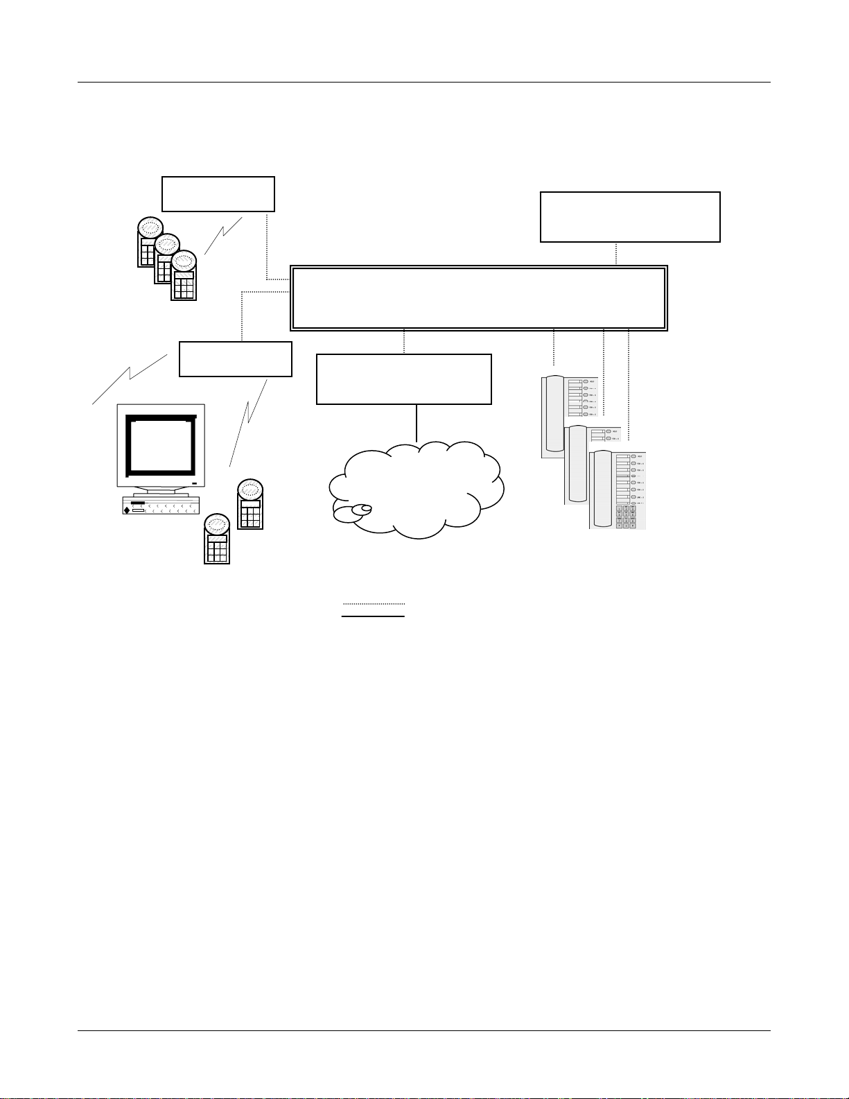
2.2 System Diagram
The following diagram shows the components residing on a network with the Avaya Call Server,
access points (APs), and wireless LAN Ethernet Switched Hub:
access point
Avaya Voice Priority
Processor
Ethernet switch
Wireless
Telephones
access point
Avaya Call Server
Wireless
POS
PSTN
or
PBX
Avaya IP
Phones
Ethernet cable
Phone cable
21-300352, Issue 2, July 2005 Page 9
Page 10

Avaya, Inc. Configuration and Administration—AVAYA 3616/3620/3626 WT
Avaya CCMS IP, Avaya Call Server, with Avaya 4612 IP Telephone Emulation
2.3 System Components
• 3616 Wireless IP Telephone – The 3616 Wireless IP Telephone is a lightweight, durable handset
specifically designed for mobile workplace use within a facility using the Avaya Call Server and
802.11 APs in a wireless LAN.
• 3620 Wireless IP Telephone –The 3620 Wireless Telephone is uniquely designed to meet the
challenging needs of the healthcare workplace. With more durable plastics, backlit keypad, and
multiple charging options, this handset is especially suited for 24-hour shift-based environments.
Note that the battery pack for the 3620 is not interchangable with the battery pack for the 3616.
• 3626 Wireless IP Telephone – The 3626 Wireless IP Telephone offers a durable design with
push-to-talk functionality.
Wireless Telephone functionality is provided by emulating the Avaya IP 4612 telephone. The 3600
Series Wireless Telephones support five predefined feature keys and a mixture of twelve
programmable line and feature keys. Among other features, the Wireless Telephone can receive
calls directly, receive transferred calls, transfer calls to other extensions, make conference calls,
and make outside and long distance calls (subject to the restrictions applied in your facility.) The
Wireless Telephones are to be used on-premises; they are not cellular or satellite phones.
3600 Series Wireless Telephones use direct sequence spread spectrum radio technology (DS) to
transmit audio packets over wireless LAN APs that support the Avaya Wireless PC card.
• Avaya Voice Priority Processor – SpectraLink Voice Priority (SVP) is the Quality of Service
(QoS) mechanism that is implemented in the Wireless Telephone and AP to enhance voice quality
over the wireless network. SVP gives preference to voice packets over data packets on the wireless
medium, increasing the probability that all voice packets are transmitted efficiently and with
minimum or no delay. SVP is fully compliant with the IEEE 802.11 and 802.11b standards.
The Avaya Voice Priority Processor is an Ethernet LAN appliance that works with the AP to
provide QoS on the wireless LAN. All packets to and from 3600 Series Wireless Telephones pass
through the Avaya Voice Priority Processor and are encapsulated for prioritization as they are
routed to and from the Avaya Call Server.
Avaya Call Server – the call-processing component of the Avaya IP telephony solution.
•
• Access Points – provide the connection between the wired Ethernet LAN and the wireless
(802.11) LAN. Access points must be positioned in all areas where Wireless Telephones will be
used. The number and placement of access points will affect the coverage area and capacity of the
wireless system. Typically, the requirements for use of 3600 Series Wireless Telephones are
similar to that of wireless data devices.
•
Ethernet Switch – interconnects multiple network devices, including the Avaya Voice Priority
Processor, Avaya Call Server, Avaya IP Phones and the access points. Ethernet switches provide
the highest performance networks, which can handle combined voice and data traffic, and are
required when using the 3600 Series Wireless Telephones.
Although a single Ethernet switch network is recommended, the Wireless Telephones and the
Avaya Voice Priority Processor can operate in larger, more complex networks, including networks
with multiple Ethernet switches, routers, VLANs and/or multiple subnets. However, in such
networks, it is possible for the Quality of Service (QoS) features of the Avaya Voice Priority
Processor to be compromised and voice quality may suffer. Any network that consists of more than
a single Ethernet switch should be thoroughly tested to ensure any quality issues are detected.
21-300352, Issue 2, July 2005 Page 10
Page 11

Avaya, Inc. Configuration and Administration—AVAYA 3616/3620/3626 WT
Note that the 3600 Series Wireless Telephones cannot “roam” from one subnet to another. If
routers and multiple subnets are in use, the Wireless Telephones must only use access points
attached to a single subnet, or be powered off and back on to switch to a different subnet.
• Avaya IP Phone – The wired-LAN desk sets provided by Avaya for use with the Avaya Call
Server.
• TFTP Server – Required in the system to distribute software to the Wireless Telephones. May be
on a different subnet than the Avaya Call Server, Avaya Voice Priority Processor, access points
and/or Wireless IP Telephones.
The Avaya Voice Priority Processor, all IP Wireless Telephones, and all
access points must be on the same subnet.
Avaya CCMS IP, Avaya Call Server, with Avaya 4612 IP Telephone Emulation
21-300352, Issue 2, July 2005 Page 11
Page 12
Avaya, Inc. Configuration and Administration—AVAYA 3616/3620/3626 WT
Avaya CCMS IP, Avaya Call Server, with Avaya 4612 IP Telephone Emulation
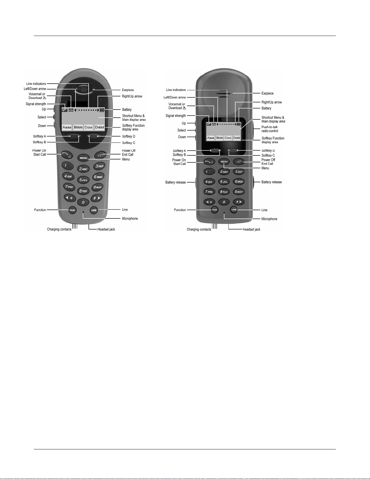
3. The 3600 Series Wireless Telephones
3616/3620 3626
3.1 Specifications
Radio frequency 2.4000 – 2.4835 GHz
Transmission type Direct Sequence Spread Spectrum (DSSS)
Transmit data rate up to 11 Mb/s
Radio QoS SpectraLink Voice Priority (SVP) –WMM
Wireless security Wired Equivalent Privacy (WEP), 40-bit and 128-bit; Cisco FSR; WPA-
PSK, WPA2-PSK
FCC certification Part 15.247
Management DHCP, TFTP
Voice encoding G.711, G.729a/ab
VoIP Protocols CCMS
Transmit power 100 mW peak, < 10 mW average
Display 2 x 16 and 4 x 18 character alphanumeric, plus line and status indicators
3616 Dimensions 5.5” x 2.0” x 0.9”
3626 Dimensions 5.9” x 2.2” x 1.0”
3616 Weight 4.2 ounces
3626 Weight 6.0 ounces
Battery capacity 4 hours talk time, 80 hours standby (30 hours standby if PTT is enabled)
21-300352, Issue 2, July 2005 Page 12
Page 13
Avaya, Inc. Configuration and Administration—AVAYA 3616/3620/3626 WT
Avaya CCMS IP, Avaya Call Server, with Avaya 4612 IP Telephone Emulation
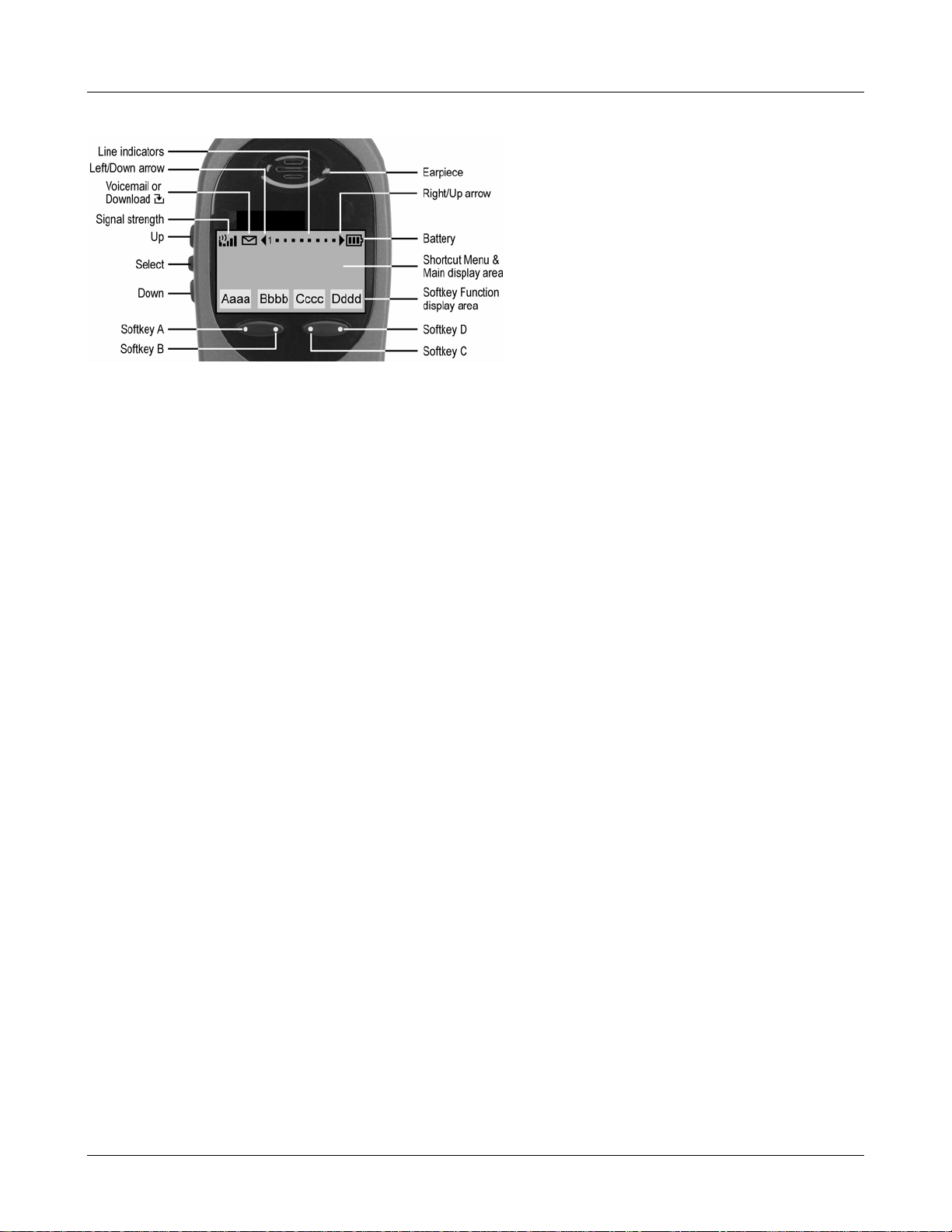
3.2 The Display
Alphanumeric
The 3600 Series Wireless Telephones displays information received from the PBX in two lines of 16
alphanumeric characters each. Display information provided by the Avaya Call Server when the
Wireless Telephone is off-hook will be passed directly to the Wireless Telephone display in an
emulation of the Avaya 4612 IP Telephone display handling. Certain characters may be used by the
Avaya Call Server that are not implemented in the Wireless Telephone such as definable and special
characters.
In the CCMS environment, the
MENU key is unavailable. Press the FCN key while off hook to scroll
through system features. In this mode, the display has four lines and up to 18 characters. Press the
shortcut key to activate the feature. Softkeys are programmed to the fixed feature keys of the Avaya
4612 IP Telephone
Signal Strength
The Signal Strength icon indicates the strength of the signal from the access point and can assist the
user in determining if the WT is moving out of range. It is always present on the display in the upper
left corner.
Battery Charge
The Battery icon indicates the amount of charge remaining in the Battery Pack. There are three levels
and when only one level remains, the Battery Pack needs to be charged. It is always present on the
display in the upper right corner.
Voicemail
The Voicemail icon is activated when a new voice mail message is received if the feature is supported
by the phone emulation. It appears to the right of the Signal Strength icon.
Download
Indicates that the WT is checking for or downloading code. This icon only appears while the WT is
running the over-the-air downloader. It appears to the right of the Signal Strength icon in the same
location as the Voicemail icon.
21-300352, Issue 2, July 2005 Page 13
Page 14

Avaya, Inc. Configuration and Administration—AVAYA 3616/3620/3626 WT
Avaya CCMS IP, Avaya Call Server, with Avaya 4612 IP Telephone Emulation
3.3 Startup Sequence
The Wireless Telephone goes through an initialization sequence at startup. The line icons 1-9 display
and count down as the Wireless Telephone steps through this sequence. If there is any difficulty at any
step that prevents initialization from continuing, an error message will display and the related icon(s)
will stay on. Please see the error table at the back of this document for instructions on how to handle
error messages that occur during initialization.
Icon The icon(s) shown in bold turns off when:
123456789 The Wireless Telephone has located and authenticated and associated
with at least one AP, and is proceeding to bring up higher-layer
networking functions.
12345678 The Wireless Telephone is either configured for Static IP, or if configured
for DHCP the DHCP discovery process has started.
1234567 If DHCP is configured, a DHCP response was received which contains a
good DNS server configuration.
123456 Note: Only valid on non-SRP protocol. Indicates one of the following:
Static IP configuration, or
AVPP address found in DHCP response, or
AVPP address found via DNS lookup.
12345 All networking functions are complete (notably, DHCP) and the Wireless
Telephone is proceeding with establishing the SRP link to either the
Gateway or AVPP.
1234 The SRP link is established, all network stack initialization is complete,
proceeding with application-specific initialization.
123 The CCMS application has started.
12 At least one IP address for a PBX has been identified.
1
(no icons)
EXT. =XXXXX
# = OK New =
Password = ********
# = OK
Ext. XXXXX
The Wireless Telephone has successfully registered with the PBX.
The Wireless Telephone requires verification of the extension number.
See section 7.*
The Wireless Telephone requires verification of the password.
See section 7.*
Initialization is complete. The Wireless Telephone is in standby mode
ready to receive and place calls.
* These prompts do not appear at every startup. They appear at first initialization and when certain
conditions require them as described in section 7.
21-300352, Issue 2, July 2005 Page 14
Page 15

Avaya, Inc. Configuration and Administration—AVAYA 3616/3620/3626 WT
Avaya CCMS IP, Avaya Call Server, with Avaya 4612 IP Telephone Emulation
3.4 Wireless Telephone Modes
Standby
(on-hook)
Active
(off-hook)
In the standby mode the Wireless Telephone is waiting for an incoming
call or for the user to place an outgoing call. The extension number is
shown on the display and there is no dial tone. In this mode, the Wireless
Telephone is conserving battery power and wireless LAN bandwidth.
When an incoming call occurs the handset will ring until the call is
answered by pressing the Start Call key or the End Call key is pressed to
silence the ringing.
To place a call, press the Start Call key. This transitions the Wireless
Telephone to active off-hook mode. There is a dial tone, the Wireless
Telephone is in communication with the PBX, and the display shows
information as it is received from the PBX. The user may place a call or
press the FCN or LINE key to access operations.
The Wireless Telephone is also in the active mode when a call is
received.
When an incoming call occurs during an active call, the handset will play
the second line ringing sound until the call is answered, the caller hangs
up, or the caller transfers to voice mail. If End Call is pressed, the first
call is terminated and the handset reverts to a full ring.
The active modes utilize the most bandwidth and battery power. To
conserve these resources, return the Wireless Telephone to the standby
mode when a call is completed by pressing the End Call key.
21-300352, Issue 2, July 2005 Page 15
Page 16

Avaya, Inc. Configuration and Administration—AVAYA 3616/3620/3626 WT
Avaya CCMS IP, Avaya Call Server, with Avaya 4612 IP Telephone Emulation
3.5 Wireless Telephone Displays
Status
display area
LINE display
FCN display
Displays information from the PBX in two lines of text and displays
available softkeys on the third line. The PBX text may be truncated as the
Avaya 4612 IP Telephone has 24 characters and the Wireless Telephone
display area is 16 characters.
There are 12 programmable keys that may be allocated to line
appearances or features in any combination. The phone will support up to
10 call appearances. Pressing the LINE key from the active mode
displays the list of line appearances extracted from the programmable
keys list. The line appearances are also mapped to corresponding line
icons across the top of the Wireless Telephone display.
Pressing the FCN key from the active state displays the list of
programmable keys that are not on the LINE list. OAI features, if
assigned, will also be displayed with their shortcuts. The programmable
key items that appear on this list each have a state indicator in the second
column of the display that shows a plus sign if the associated feature is
active. This second column is blank if the associated feature is not active.
The plus sign emulates a lit or blinking LED on an Avaya 4612 IP
Telephone.
21-300352, Issue 2, July 2005 Page 16
Page 17

Avaya, Inc. Configuration and Administration—AVAYA 3616/3620/3626 WT
Avaya CCMS IP, Avaya Call Server, with Avaya 4612 IP Telephone Emulation
4. Avaya Call Server Configuration
You can configure the 3600 Series Wireless Telephones as a stand-alone station or associate it with a
desk station. When the 3600 Series Wireless Telephones are associated with a desk station, the user
can make and handle calls from either the 3600 Series Wireless Telephones or the desk station.
4.1 Configuring a Standalone Station
To configure 3600 Series Wireless Telephones as a stand-alone station, you must add a station on the
Avaya Call Server for the 3600 Series Wireless Telephones.
To administer a stand-alone station on the Avaya Call Server for a Wireless Telephone:
1. From the Avaya Call Server administration software, add a new station.
2. Set “Type” to “4612.”
3. Administer a station security code.
4. Complete the remainder of the station form as you would for a desk station.
5. Repeat Steps 1 through 5 for each stand-alone Wireless Telephone.
4.2 Configuring an Associated Station
To configure 3600 Series Wireless Telephones as an associated station, you must add a station on the
Avaya Call Server for the 3600 Series Wireless Telephones and then associate that station with a desk
station.
To administer an associated station on the Avaya Call Server for a Wireless Telephone:
1. From the Avaya Call Server administration software, add a new station.
2. Set “Type” to “4612.”
3. Set “Security Code” to the same security code used for the extension to which this Wireless
Telephone will be associated (that is, the desk station). You can use a different security code,
but to make it easier for the user it is recommended that you use the same security code as the
desk station.
4. Set “Message Lamp Ext” to the extension of the associated desk station.
5. Set “Bridged Call Alerting” to “y.”
6. Set “Auto Select Any Idle Appearance” to “y.”
7. For Button Assignments, create bridged appearances to the line appearances on the desk
station.
8. Add additional feature buttons to unassigned buttons, if desired.
9. Repeat Steps 1 through 8 for each Wireless Telephone.
When making changes to feature buttons, the phone must be power
21-300352, Issue 2, July 2005 Page 17
cycled.
Page 18

Avaya, Inc. Configuration and Administration—AVAYA 3616/3620/3626 WT
Avaya CCMS IP, Avaya Call Server, with Avaya 4612 IP Telephone Emulation
5. 3600 Series Wireless Telephones Configuration
The Wireless Telephone can be automatically configured for IP address and/or ESSID by enabling
DHCP and/or ESSID Learning, respectively.
Each Wireless Telephone may be configured for site-specific requirements by opening the Admin
menu and selecting options or entering specific information. Any settings entered in the Admin menu
must conform to system settings. Only the Wireless Telephone being configured is affected by the
Admin menu settings.
The Wireless Telephone user may select several usability options from the standby menu, described
below in the User-defined Preferences section. This information is also provided in the end user
manual.
The AVAYA Configuration Cradle is an accessory device designed to automate configuration of 3600
Series Wireless Telephones. The Configuration Cradle is connected to a PC via a serial cable. A
downloadable Configuration Cradle program runs on the PC and enables the system administrator to
establish and store configuration options for system, group and user levels. A configuration plan may
be set up in the program and downloaded into a Wireless Telephone or a configured Wireless
Telephone may be placed in the cradle and its configuration may be uploaded and edited or saved.
Please see your service representative or contact Avaya Customer Service for more information about
this time-saving device.
5.1 The Admin Menu
The Admin menu contains configuration options that are stored locally (on each Wireless Telephone).
Every Wireless Telephone is independent and if the default settings are not desired, the admin options
must be set in each Wireless Telephone requiring different settings.
Opening the Admin menu
1. With the Wireless Telephone powered OFF, simultaneously press and hold the Power On and
Power Off keys.
2. Release the Power On key, wait for a single beep, then release the Power Off key. The first
option on the Admin menu displays.
If an admin password has been set, the display will require its entry before
opening the Admin menu. If no password is set, the display will proceed
directly into the Admin menu.
21-300352, Issue 2, July 2005 Page 18
Page 19

Avaya, Inc. Configuration and Administration—AVAYA 3616/3620/3626 WT
Avaya CCMS IP, Avaya Call Server, with Avaya 4612 IP Telephone Emulation
Entering and editing Admin menu options
An asterisk (*) next to an option on the display indicates that it is selected. Use the Up, Down, and
Select side buttons and the softkeys to navigate and select:
Up/Down buttons: display previous/next menu item.
Select button: selects the menu item or option.
OK softkey selects the menu item or option.
Save softkey: saves the entry.
Bksp softkey: backspaces to allow editing of entry.
Cncl softkey: cancels edit and returns to previous menu level.
Up softkey: returns to previous menu level.
Exit softkey: exits the menu (at the top level).
End Call key: exits to standby state (from any level)
Alphanumeric String Entry
1. Press the first digit/letter. The digit displays. Press the key again to scroll through the letters
associated with that key.
Example: if you press 2 repeatedly, you will see 2, A, B, and C, a, b, and c.
The following table shows which key will allow you to enter non-numeric characters or other
characters not represented on the keypad.
To Enter Press
. - _ ! # $ % & ‘ ( ) , : ; / \ = @ ~ 1
Space 0
Q,q 7
Z,z 9
2. When the correct entry displays, press Right Arrow to move on to the next character. Repeat
for each digit/letter of the entry.
3. Press the Save softkey to save the entry.
Press the Cncl softkey to abort and return to the menu without saving any changes.
The following table lists the Admin menu items. The default settings have an * prior to the option.
Detailed descriptions of each item appear below the table.
21-300352, Issue 2, July 2005 Page 19
Page 20
Avaya, Inc. Configuration and Administration—AVAYA 3616/3620/3626 WT
Avaya CCMS IP, Avaya Call Server, with Avaya 4612 IP Telephone Emulation
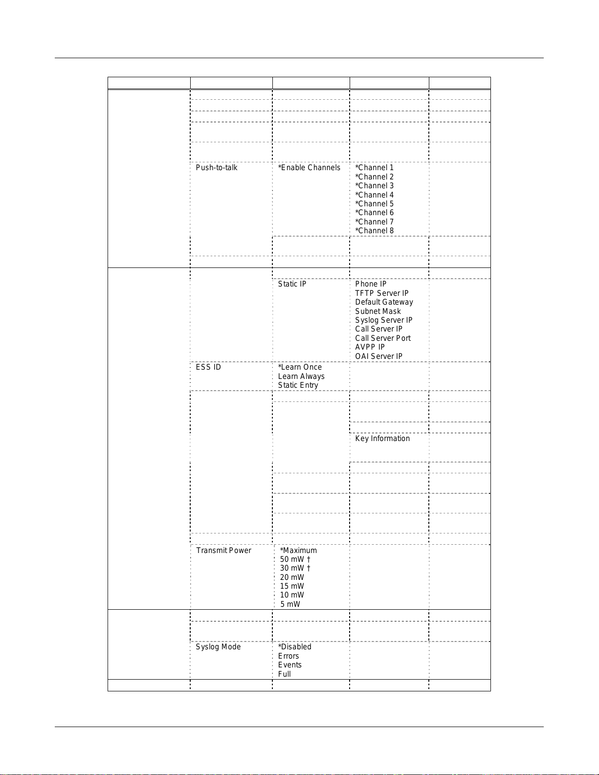
Admin menu
Admin Menu Items 2nd Level 3rd Level 4th Level 5th Level
Phone Config License Option Set Current [List per download]
Ext. xxxx
Password
IP Office IP Ofc Enabled
OAI on/off Enable OAI
Push-to-talk *Enable Channels *Channel 1
Allow/Disallow *Allow PTT
Admin Password Enter Admin P.W. Re-enter Password
Network Config IP Addresses *Use DHCP
Static IP Phone IP
ESS ID *Learn Once
Security *None
WEP Authentication Open System
WEP On/Off
Key Information Default Key
Rotation Secret
Cisco FSR Username
WPA-PSK Passphrase
WPA2-PSK Passphrase
Reg. Domain: None
Transmit Power *Maximum
Diagnostics Run Site Survey
Diagnostics Mode Diagnostics On
Syslog Mode *Disabled
Restore Defaults
* default setting †50 mW and 30 mW only appear if Regulatory Domain is set to None or 01.
Disabled
Disable OAI
Learn Always
Static Entry
50 mW †
30 mW †
20 mW
15 mW
10 mW
5 mW
*Diagnostics Off
Errors
Events
Full
What is default?
What is default?
*Channel 2
*Channel 3
*Channel 4
*Channel 5
*Channel 6
*Channel 7
*Channel 8
Disallow PTT
TFTP Server IP
Default Gateway
Subnet Mask
Syslog Server IP
Call Server IP
Call Server Port
AVPP IP
OAI Server IP
Shared Key
Key Length
Key 1-4
Password
Direct Entry
Direct Entry
21-300352, Issue 2, July 2005 Page 20
Page 21

Avaya, Inc. Configuration and Administration—AVAYA 3616/3620/3626 WT
Phone Config
License Option
Avaya CCMS IP, Avaya Call Server, with Avaya 4612 IP Telephone Emulation
License Management lets you select the VoIP protocol that your site is licensed to download
and run. The CCMS Protocol to use for the 3600 Series Wireless Telephones is
009. Any other
protocol will cause the Wireless Telephone to malfunction.
Ext.
Each 3600 Series Wireless Telephones must have an extension assigned to it, as well as having
the same extension administered in the Avaya Call Server. This extension is used to register the
Wireless Telephone with the Avaya Call Server.
Password
Each 3600 Series Wireless Telephones must have a password entered into it that matches the
password (station security code) administered in the Avaya Call Server. This password can be
up to 7 digits.
The Ext. and Password entries have been retained in the Admin menu in
the current release of firmware for compatibility. It is no longer necessary
to enter the extension or password using the Admin menus. See section:
Avaya Call Server Integration Factors for a complete explanation of the
extension and password assignments.
IP Office
For proper display handling on the Wireless Telephone, enable the IP Office when using the IP
Office system.
OAI On/Off
The Open Application Interface (OAI) enables third-party computer applications to display
alphanumeric messages on the WT display and take input from the WT keypad. Refer to the
Open Application Interface (OAI) Specification (Version 1.2) documentation for information
about administering the OAI Gateway and the services it can provide.
If you have an OAI Gateway installed in your system, OAI may be optionally enabled in each
WT. You may select whether the WT should attempt to connect to the OEM OAI Gateway by
choosing either the Enable or Disable options in this menu.
If OAI is enabled, and an OAI IP Address is available to the telephone (either via DHCP or
Static IP configuration), the telephone will communicate with the OAI Server at power on, and
periodically while it is powered on. If you don’t have an OEM OAI Gateway installed at your
site, you should disable the OAI feature to preserve network bandwidth and battery life.
Push-to-talk
All eight Push-to-talk channels are allowed by default. To toggle the allowed status of any
channel, select
side button. Allowed channels are displayed with an * in the left column. Only those channels
allowed in the Admin menu will appear on the Standby menu where they can be enabled or
disabled by the end user. To disallow push-to-talk entirely, select
select Disallow PTT.
Admin Password
The Admin Password controls access to the administration functions in the Admin Menu. The
password must be set in each Wireless Telephone for which controlled access is desired.
Wireless Telephones are shipped without any Admin Menu password. Data entry for the
password uses the alphanumeric string entry technique. Type the password and press the Save
Allowed Channels, scroll to the channel to be disallowed and press the Select
Allow/Disallow, scroll to and
21-300352, Issue 2, July 2005 Page 21
Page 22

Avaya, Inc. Configuration and Administration—AVAYA 3616/3620/3626 WT
softkey. A confirmation prompt will appear. Type the password again and press the Save
softkey. If the passwords match, the Admin password has been set.
Network Config
IP Address
There are two modes in which the Wireless Telephone can operate: DHCP enabled or Static IP.
Select the mode for operation from the IP Address menu:
If you Save with no entry, the password is erased and the display will
not require it before displaying the Admin Menu.
* Use DHCP: will use Dynamic Host Configuration Protocol to assign an IP Address
each time the Wireless Telephone is turned on. If DHCP is enabled, the Wireless
Telephone also receives all other IP Address configurations from the DHCP server.
Static IP: allows you to manually set a fixed IP Address. If selected, the Wireless
Telephone will prompt for the IP Addresses of each configurable network component.
When entering addresses, enter the digits only, including leading zeroes. No periods are
required.
Regardless of the mode in which the Wireless Telephone is operating, the following
components must be configured:
Avaya CCMS IP, Avaya Call Server, with Avaya 4612 IP Telephone Emulation
Phone IP – the IP Address of the Wireless Telephone. This is automatically assigned if
DHCP is used. If using Static IP configuration, you must obtain a unique IP Address for
each phone from your network administrator.
TFTP Server IP – the IP address of a TFTP server on your network which holds software
images for updating the Wireless Telephones. If this feature is configured (not set to
0.0.0.0 or 255.255.255.255) with either Static IP configuration or using DHCP option
66 (TFTP Server), or the Boot server/next server (siaddr) field, the Wireless Telephone
will check for newer software each time it is powered on or comes back into range of
your network. This check takes only a second and ensures that all Wireless Telephones
in your network are kept up-to-date with the same version of software.
Default Gateway and Subnet Mask – used to identify subnets, when using a complex
network which includes routers. Both of these must be configured either with an IP
address under Static IP (not set to 000.000.000.000 or 255.255.255.255) or with DHCP
for the Wireless Telephone to contact any network components on a different subnet. If
configured on the DHCP server, use option 3 for the Default Gateway and option 1 for
the Subnet Mask. Contact your network administrator for the proper settings for your
network.
Note that the Wireless Telephones cannot “roam” across subnets,
since they cannot change their IP address while operational. Ensure
that all your access points are attached to the same subnet for proper
operation. The Wireless Telephone can change subnets if DHCP is
enabled and the Wireless Telephone is powered off then back on
when within range of access points on the new subnet.
Syslog Server IP – the IP address of the syslog server. See the Diagnostics section for
more information.
21-300352, Issue 2, July 2005 Page 22
Page 23

Avaya, Inc. Configuration and Administration—AVAYA 3616/3620/3626 WT
Call Server IP – the IP address of the Avaya Call Server, such as the DEFINITY
Avaya CCMS IP, Avaya Call Server, with Avaya 4612 IP Telephone Emulation
MultiVantage system. If using Static IP configuration, this is the IP address of the Call
Server. If DHCP is being used, the Wireless Telephone will try the following, in order:
DHCP Option 43 (Keyword MCIPADD), DHCP Option 176 (Keyword MCIPADD),
and if DHCP Option 6 (DNS Server) and Option 15 (Domain Name) are configured,
DNS lookup of server names found in the above options, and finally the DNS lookup of
“AvayaCallServer.DOMAIN”.
Call Server Port – the IP port address of the Avaya Call Server, such as the Avaya
communication manager. This port normally defaults to 1719, and is rarely changed.
The port number entered must be coordinated with the administration of the Call Server,
otherwise the wireless phone will not be able to register with the Call Server. If DHCP
is being used, this can be changed via DHCP Option 43 (Keywork MCPORT) or DHCP
Option 176 (Keyword MCPORT).
AVPP IP – the IP address of the Avaya Voice Priority Processor. If using Static IP
configuration, this is simply the IP address of the Avaya Voice Priority Processor. Note
that the Avaya Voice Priority Processor must be statically configured to have a
permanent IP address. If DHCP is being used, the Wireless Telephone will try the
following, in order: the DHCP option 151, then a DNS lookup of “SLNKSVP2” if the
DHCP options 6 (DNS Server) and 15 (Domain Name) are configured.
ESSID
OAI Server IP – the IP address of the AVAYA OAI Gateway. If using static IP
configuration, this is simply the IP address of the AVAYA OAI Gateway. If DHCP is
being used, the Wireless Telephone will try the DHCP option 152.
Select the option that will enable the Wireless Telephone to acquire APs with the correct
ESSID (Extended Service Set ID, aka SSID) each time it is turned on.
Note about Automatic Learn options: Broadcast ESSID must be enabled in the access points for
ESSID learning to function. Refer to the Configuration Note for your access point or call your
access point vendor for specifics. Overlapping wireless systems complicate the use of ESSID
learning as the Wireless Telephone in an overlapping area could receive conflicting signals. If
this is the situation at your site, use Static Entry or Learn Once in an area without overlapping
ESSIDs.
* Learn Once: allows the Wireless Telephone to scan all ESSIDs for a DHCP server
and/or TFTP server. Once either is found, the Wireless Telephone retains the ESSID
from whichever access point it associates with at that point. When overlapping wireless
systems exist, the Learn Once feature allows the Wireless Telephone to use only the
ESSID established at first learn at all subsequent power ons. This ESSID is retained by
the Wireless Telephone until the ESSID option is reselected.
Learn Always: allows the Wireless Telephone to automatically learn the ESSID at each
power on or loss of contact with the wireless LAN (out of range). This may be useful if
the Wireless Telephone will be used at more than one site.
Static Entry: If your access points do not accept broadcast ESSID or if there are
overlapping wireless systems in use at the site, enter the correct ESSID manually.
Security
*NONE
21-300352, Issue 2, July 2005 Page 23
disables any 802.11 encryption or security authentication mechanisms.
Page 24

Avaya, Inc. Configuration and Administration—AVAYA 3616/3620/3626 WT
Avaya CCMS IP, Avaya Call Server, with Avaya 4612 IP Telephone Emulation
options to match exactly the settings in your APs.
Encryption codes display as they are entered. For security reasons
For WEP, WPA-PSK and WPA2 PSK set each of the following
codes will not display when a user returns to the Admin menu,
Encryption options.
WEP (Wired Equivalent Privacy) is a wireless encryption protocol that encrypts data frames on
the wireless medium allowing for greater security in the wireless network. If WEP/Encryption
is required at this site, you must configure each Wireless Telephone to correspond with the
encryption protocol set up in the access points. Select the entries from the options below to
enable the Wireless Telephone to acquire the system.
Authentication
Select either Open System or Shared Key.
WEP On/Off
Select either WEP Off or WEP On.
Key Information
Default Key: Enter the key # specified for use by the Wireless Telephones. This will
be 1 through 4.
Key Length: Select either 40-bit or 128-bit depending on the key length specified for
use at this location.
Key 1-4: Scroll to the key option that corresponds to the Default Key that was entered
above. Enter the encryption key as a sequence of hexadecimal characters. (Use the 2
and 3 keys to access hexadecimal digits A-F, use the Right Arrow key to advance to
the next digit, and the Left Arrow key to backspace.) For 40-bit keys you will need
to enter 10 digits, for 128-bit keys you will need to enter 26 digits. The display will
scroll as needed.
Rotation Secret: This is used for proprietary WEP key rotation. Refer to your custom
document if this feature is supported in your system.
Cisco FSR (Fast Secure Roaming) In order to provide the highest level of security without
compromising voice quality on Cisco Aironet wireless LAN access points, Avaya and Cisco
Systems have cooperated to implement the Fast Secure Roaming mechanism. FSR is designed
to minimize call interruptions for AVAYA Wireless Telephone users as they roam throughout a
facility. Existing Aironet 350, 1100, and 1200 APs may require a firmware upgrade to support
FSR. Cisco FSR requires advanced configuration of the Cisco access points in your site. See
your Cisco representative for detailed documentation on configuring your access points and
other required security services on your wired network. To configure Cisco FSR in your
AVAYA Wireless Telephone, you must enter a Radius Server username and password into
each handset.
Username: Enter a username that matches an entry on your Radius server. Usernames
are alphanumeric strings, and can be entered using the alphanumeric string entry
technique.
Password: Enter the password that corresponds to this Username.
WPA-PSK: The security features of WPA (Wi-Fi Protected Access) using PSK (Pre-Shared
Key) are available and may be used if supported by the access points in the facility. Select
21-300352, Issue 2, July 2005 Page 24
Page 25

Avaya, Inc. Configuration and Administration—AVAYA 3616/3620/3626 WT
Avaya CCMS IP, Avaya Call Server, with Avaya 4612 IP Telephone Emulation
either Passphrase and enter a passphrase between eight and 63 characters in length or Direct
Entry
and enter the 256-bit key code.
WPA2-PSK: The security features of WPA2 (Wi-Fi Protected Access) using PSK (Pre-Shared
Key) are available and may be used if supported by the access points in the facility. Select
either
Entry
Passphrase and enter a passphrase between eight and 63 characters in length or Direct
and enter the 256-bit key code.
Consult the Configuration Note for the access points (APs) installed in
your facility for information on which of the WPA versions are
recommended by Avaya engineering. Configure the recommended
version on the AP and select the corresponding option on the Admin
menu.
Regulatory Domain
The Regulatory Domain will default to None on the Wireless Telephone display. FCC
requirements dictate that the menu for changing the domain be available by password, which in
our case is the LINE key. To change the domain, press LINE and then enter the digits that
represent the site’s domain. Note that both digits must be entered.
01 - North America
02 - Europe (except Spain and France); Japan (channels 1-13)
04 - Spain
05 – France
As of this writing, Spain and France are adopting the general European
Regulatory rules. Check with your wireless LAN administrator or
supplier for which domain to enter in these countries.
Transmit Power
Available transmit power is regulated by domain. The Regulatory Domain setting above affects
the options available for this setting. The default setting is Maximum which in North America is
100 mW. The Maximum in other domains is 30 mW. Transmit Power may be set to a lower
number if necessary by selecting one of the other levels. If changed from the default, ensure the
Transmit Power setting is the same on all Wireless Telephones and all APs.
Diagnostics
Run Site Survey
The Site Survey mode is activated by selecting this option. Site survey starts running
immediately upon selecting this option. See the Diagnostic Tools section for more information
about Site Survey.
Diagnostics Mode
See the Diagnostic Tools section for a detailed explanation of the Diagnostics Mode options.
Syslog Mode
See the Diagnostic Tools section for a detailed explanation of the Diagnostics Mode options.
Restore Defaults
The Restore Defaults option will set all user and administrative parameters to their factory defaults.
21-300352, Issue 2, July 2005 Page 25
Page 26

Avaya, Inc. Configuration and Administration—AVAYA 3616/3620/3626 WT
Avaya CCMS IP, Avaya Call Server, with Avaya 4612 IP Telephone Emulation
5.2 User-defined Preferences
The following user-defined preferences are also covered in the Avaya 3600 Series Wireless
Telephones user guides. The system administrator can refer to this list for more information about
customizing Wireless Telephone settings.
To configure the following options, the Wireless Telephone must acquire the system (no error message
may display) and be in standby mode at the extension display. This is the standby state. While in the
standby state, press and hold FCN briefly to open the user options menu. Use the following keys to
display and select options:
Up/Down buttons: display previous/next menu item.
button: selects the menu item or option.
Select
OK softkey selects the menu item or option.
Save softkey: saves the entry.
Bksp softkey: backspaces to allow editing of entry.
Cncl softkey: cancels edit and returns to previous menu level.
Up softkey: returns to previous menu level.
Exit softkey: exits the menu (at the top level).
End Call key: exits to standby state (from any level)
21-300352, Issue 2, July 2005 Page 26
Page 27

Avaya, Inc. Configuration and Administration—AVAYA 3616/3620/3626 WT
Avaya CCMS IP, Avaya Call Server, with Avaya 4612 IP Telephone Emulation
Standby menu
Standby menu item 2nd Level 3rd Level 4th Level
Lock Keys
Ring Options Telephone Ring Ring Cadence Off
Ring Tone *Tone 1
Ring Volume Bars
Vibrate Cadence *Off
Ring Delay* *No Delay
Auxiliary Ring 1
Auxiliary Ring 2
Phone Options Noise Mode *Normal
Key Tones *Enable Tones
Warning Tones *Enable Warnings
Display Contrast Contrast % Default = 50%
Keypad Autolock *Disable
System Info Phone IP Add
Call Server IP
Call Server Port
Push-to-talk
Enable/Disable PTT Enabled
Audio Volume Bars
Tone Volume Bars
* default setting
*shows up when Ring Cadence and Vibrate Cadence are both set to a value other than “Off”
1
Server IP Addr
Firmware Version
Channel Current Channel: X
High
Severe
Disable Tones
Disable Warnings
5 seconds
10 seconds
20 seconds
1 2 3 4 5 6 7 8
New Channel = ?
*PTT Disabled
*PBX
Continuous
Short Pulse
Long Pulse
Tone 2
Tone 3
Tone 4
Tone 5
PBX
Continuous
Short Pulse
Long Pulse
5 Second Delay
10 Second Delay
1
Push-to-talk is available only on the AVAYA 3626 Wireless Telephone.
21-300352, Issue 2, July 2005 Page 27
Page 28

Avaya, Inc. Configuration and Administration—AVAYA 3616/3620/3626 WT
Main Menu: Scroll through the list of options by pressing the Up and Down side buttons. Select an
Avaya CCMS IP, Avaya Call Server, with Avaya 4612 IP Telephone Emulation
option by pressing the Select side button.
Lock Keys
Ring Options
Phone Options
System Info
Call Server IP
Call Server Port
Push-to-Talk [3626]
OK Exit
Lock Keys: When enabled, the Keypad Lock option will lock the keypad immediately. If the keypad is
locked, it may be unlocked by the end user pressing the
Ring Options: The Ring Type option allows the user to set the ring for three separate functions.
Unlk softkey and then the # key.
Telephone ring is used for usual telephony functions. The Auxiliary Rings may be used to set
different ringing patterns for OAI applications.
Telephone Ring
Auxiliary Ring 1
Auxiliary Ring 2
OK Up
Telephone Ring: Telephone Ring allows the user to set a distinctive ring style, volume and
sequence. Select from an audible ring or a vibrate-only ring or a vibrate ring along with or
followed by an audible ring.
Ring Cadence
Ring Tone
Ring Volume
Vibrate Cadence
Ring Delay
OK Up
Ring Cadence: The cadence is the rhythm of the ring. It may be set to a pre-programmed
ring cadence or it may be set to obtain its cadence from the PBX. The PBX option is
designed to utilize any distinctive rings sent by the PBX while allowing the user to set
unique rings for auxiliary applications.
Off
PBX
Continuous
Short Pulse
Long Pulse
OK Up
Off: silent
PBX: PBX determines ring cadence (e.g. the PBX may send rings that
differentiate between internal and external calls.)
Continuous: rings continually until answered
Short Pulse: rings in short bursts
21-300352, Issue 2, July 2005 Page 28
Page 29

Avaya, Inc. Configuration and Administration—AVAYA 3616/3620/3626 WT
Avaya CCMS IP, Avaya Call Server, with Avaya 4612 IP Telephone Emulation
Long Pulse: rings in long bursts
Ring Tone: select from five available tones (scroll to Tone 5 option). The Play softkey
allows the user to preview the tone before selecting. If Ring Cadence is turned off, the
Ring Tone option will not appear on the menu.
Tone 1
Tone 2
Tone 3
Tone 4
Tone 5
OK Play Up
Ring Volume: The user may select a volume level by pressing the Up and Down side
buttons and then pressing the OK softkey. The graduated volume bar indicates the
levels. This setting may be overridden by adjusting volume while the handset is ringing.
Auxiliary Ring 1 and Ring 2: Auxiliary rings are designed to be utilized by OAI applications,
enabling the user to set a distinctive ring for these applications.
Phone Options
Mode: Provides options that describe the noise level in your environment. Selecting the
Noise
correct option will adjust the Wireless Telephone to account for background noise. Select
Normal: for most office environments; High: for moderate background noise; or Severe: for
extremely noisy conditions. Use of the non-Normal modes is not recommended unless you are
in a loud environment or you may find it difficult to be heard on your Wireless Telephone.
Key Tones: Key tones may be turned on or off and determine if tones play when keys are
pressed. Key tones are enabled by default.
Vibrate Cadence
Ring Delay
: Vibrate Cadence options are the same as for Ring Cadence
: Ring Delay determines how long the vibrate cadence will play before the
audible ring starts. If the Ring Cadence or Vibrate Cadence is turned off, the Ring
Delay option will not appear on the menu.
No Delay
5 Second Delay
10 Second Delay
OK UP
Warning Tones: The Wireless Telephone plays various warning tones such as system up or
down, out of range, etc. These tones may be turned on or off and are enabled by default.
Display Contrast: The display may need to be adjusted for different lighting situations. Contrast
may be set by pressing the
Up and Down side buttons until the desired contrast is displayed and
then pressing the OK softkey. The minimum setting is 30% and the maximum setting is 83%.
Keypad Autolock: The Wireless Telephone may be set to lock the keypad automatically when in
standby mode. The automatic locking function of the keypad may be disabled (the default) or
adjusted for a 5, 10 or 20 second delay before locking.
System Info
Phone IP Addr
Server IP Addr: Displays the IP address of the AVPP Server and the OAI Server (if installed).
21-300352, Issue 2, July 2005 Page 29
: Displays the IP address currently assigned to the Wireless Telephone.
Page 30

Avaya, Inc. Configuration and Administration—AVAYA 3616/3620/3626 WT
Firmware Version: displays the software version running the Wireless Telephone. The MAC
Avaya CCMS IP, Avaya Call Server, with Avaya 4612 IP Telephone Emulation
address is the hardware identification number and is set at the factory. Three code numbers
correspond to the three files that each version uses.
(MAC address)
(downloader code) (functional code)
(phintl file)
OK Up
Downloader: pd11gl3.bin
Functional: pd11xxx3.bin
Phintl: phintl24.bin or pi11xxx.bin
Call Server IP: This option displays the IP address of the Avaya Call Server with which the Wireless
Telephone is registered. The IP address is not set here; it is merely displayed and may not be
changed.
Call Server Port: This option displays the UDP port number used when registering with the Avaya Call
Server. The port address is not set here; it is merely displayed and may not be changed
Push-to-Talk: The AVAYA 3626 Wireless Telephone incorporates push-to-talk functionality. PTT may
be allowed or disallowed in the Admin menu. If allowed, the user may enable or disable
locally, and may set the channel, tone volume and audio volume. The menu for push-to-talk
does not appear if PTT is disallowed on the Admin menu or if no channel is enabled on the
Admin menu.
Channel
Enable/Disable
Audio Volume
Tone V olume
OK Up
Channel: The user may enable any PTT channel that has been allowed in the Admin menu by
entering the corresponding number from the keypad. If PTT has been enabled in this handset,
the default channel is the lowest allowed channel as set in the Admin menu.
Current Channel: X
1 2 3 4 5 6 7 8
New Channel = ?
Up
Enable/Disable: The user may enable or disable PTT on this handset. PTT is disabled by
default.
PTT Enabled
PTT Disabled
OK Up
Audio Volume, Tone Volume: The user may select a volume level by pressing the Up and Down
side buttons and then pressing the
OK softkey. The graduated volume bar indicates the levels.
The Audio Volume setting may be overridden by adjusting volume while the handset is in a
Push-to-talk call.
21-300352, Issue 2, July 2005 Page 30
Page 31

Avaya, Inc. Configuration and Administration—AVAYA 3616/3620/3626 WT
If PTT is allowed in the Admin menu and enabled by the user, standby
time is decreased to about 30 hours.
Avaya CCMS IP, Avaya Call Server, with Avaya 4612 IP Telephone Emulation
21-300352, Issue 2, July 2005 Page 31
Page 32

Avaya, Inc. Configuration and Administration—AVAYA 3616/3620/3626 WT
Avaya CCMS IP, Avaya Call Server, with Avaya 4612 IP Telephone Emulation
6. License Management
The 3600 Series Wireless Telephones supports a number of different IP protocol integrations. All
3600 Series Wireless Telephones are shipped from Avaya with a generic software load that allows
them to associate to a wireless LAN and download their functional software from a TFTP server. The
Wireless Telephones will not function properly without downloading appropriate software.
The following details the process to properly configure 3600 Series Wireless Telephones and
download software via over-the-air file transfer.
6.1 Requirements
• A wireless LAN must be properly configured and operational through the use of 802.11b
wireless access points.
• The Avaya Call Server must also be connected to your network and completely operational.
• A TFTP Server must be available on the network in order to load the appropriate software into
the Wireless Telephones.
• The AVPP Server is installed and properly configured.
• Finally, ensure that the Battery Pack on the Wireless Telephone is fully charged.
6.2 Configuration Process
1. Download the latest IP software for the 3600 Series Wireless Telephones from:
http://www.spectralink.com/service/software.php .
2. Load the latest version of the 3600 Series Wireless Telephones code and place it on the TFTP
Server and ensure the TFTP Server is started. The five files that are needed must be named:
slnk_cfg.cfg
pd11gl3.bin
pd11ccd.bin
pd11ccd3.bin
pi110003.bin.
3. If statically assigning IP addresses, ensure that the
Server IP, Subnet Mask, and Default Gate way information are accurate in the Admin Menu. If
using a DHCP Server, ensure that the DHCP option is set. See “3600 Series Wireless
Telephones Configuration” section for detailed configuration instructions.
4. Ensure the Wireless Telephone has properly configured
within the Admin Menu. If you are accepting broadcast
handset will automatically learn the ESSID information when powering on. See “3600 Series
Wireless Telephones” section for detailed configuration instructions.
IP Address, TFTP Server IP, AVPP IP, Call
ESSID and Reg Domain Information
ESSIDs at your access points, the
5. Using the Admin Menu on the Wireless Telephone, ensure the
009. This ensures the handset will check for the proper software files each time it powers
set to
License Option menu option is
on. See “3600 Series Wireless Telephones Configuration” section for detailed configuration
instructions.
6. Power cycle the Wireless Telephone.
21-300352, Issue 2, July 2005 Page 32
Page 33

Avaya, Inc. Configuration and Administration—AVAYA 3616/3620/3626 WT
7. The code will now download to the handset. The status bar will increment fully across the
display for each function that is being performed in the download process. Upon completion of
the update process, the handset will re-boot with the new firmware.
8. After code has been downloaded for the first time, the Wireless Telephone will ask for an
extension and password. Once these have been entered, the phone will register with the Avaya
Call Server.
For future software upgrades, simply update the files that are stored on the
TFTP Server. Each time the Wireless Telephone is powered up, it will
check with the TFTP Server to ensure it has the proper software version.
If a new version of code is downloaded, the currently entered extension
and password will be preserved.
Avaya CCMS IP, Avaya Call Server, with Avaya 4612 IP Telephone Emulation
21-300352, Issue 2, July 2005 Page 33
Page 34

Avaya, Inc. Configuration and Administration—AVAYA 3616/3620/3626 WT
Avaya CCMS IP, Avaya Call Server, with Avaya 4612 IP Telephone Emulation
7. Avaya Call Server Integration Factors
This section describes the mapping between the emulated Avaya 4612 IP Telephone and the 3600
Series Wireless Telephones.
Voice Messaging Access
Voicemail is accessed on the Wireless Telephone as FCN + a character that corresponds to the
administered button.
CODECs
The 3600 Series Wireless Telephones are compatible with the G.711 and G.729a/ab codecs. There is
no setting required on the WT. If the wrong codec is used, there will be no voice path.
DHCP
Dynamic Host Configuration Protocol (DHCP) is a standardized protocol that enables clients to be
dynamically assigned with various configuration parameters, such as an IP address, subnet mask,
default gateway, and other critical network configuration information. DHCP servers centrally manage
such configuration data, and are configured by network administrators with settings that are
appropriate for a given network environment. The Wireless Telephone will use the following DHCP
options if DHCP use is enabled:
Option Meaning
1 Subnet Mask
3 Default Gateway
6 DNS Server
7 Syslog Server
15 Domain Name
43 Avaya Specific Options
60 Vendor Cla ss ID
66 TFTP Server
151 Avaya Voice Priority Processor
152 NL OAI Gateway
176 Avaya Specific Options
siaddr Boot serve r o r next server
TFTP
The Wireless Telephone uses TFTP to update its software over the 802.11 wireless LAN.
DNS
Domain Name System (DNS), an industry-standard protocol, locates computers on an IP-based
network. IP networks rely on number-based addresses to move information on the network. However,
users are better at remembering friendly names than number-based addresses, so, it is necessary to
translate user-friendly names into addresses that the network can recognize. The Wireless Telephone
will use DNS to automatically translate names into IP addresses for these components: TFTP Server,
Avaya Voice Priority Processor, and Avaya Call Server.
21-300352, Issue 2, July 2005 Page 34
Page 35

Avaya, Inc. Configuration and Administration—AVAYA 3616/3620/3626 WT
Avaya CCMS IP, Avaya Call Server, with Avaya 4612 IP Telephone Emulation
Entering an Extension and Password
Several conditions (new phone, Extension Error, Password Error, and Extension in use) can result in
the Wireless Telephone asking the user for a new extension and password. The entry process is
described below. When a new extension or password is being entered, the asterisk (*) key can be used
to back up and correct an error.
The Wireless Telephone will display:
Ext. =XXX
#=OK New =
At this point, a new extension can be entered, or if the # key is pressed, the Wireless Telephone
will retain the current extension.
After a new extension is entered, press # to continue.
The Wireless Telephone will then display:
Password = ********
# = OK
A new password can be entered at this time, or if the # key is pressed, the Wireless Telephone
will continue with its current password.
After a new password is entered, press # to continue.
Extension Error
If the Call Server (or all Call Servers if there are more than one) does not recognize the extension the
phone is trying to register with, the Wireless Telephone will display:
Extension Error
This will last 5 seconds, and then the Wireless Telephone will ask the user to enter a new extension
and password.
Password Error
If the Wireless Telephone has an incorrect password, the display will show:
Password Error
# to continue
Press # to continue on to enter a new extension and password.
Extension Override
The Avaya Call Server will detect when a Wireless Telephone tries to register with the same extension
as any telephone that is already registered to that extension. If this happens, the Wireless IP Phone will
display:
Extension in use
# to continue
Press # to continue.
If the user chooses to continue on with the override information, the Wireless Telephone will register
with the override bit set. Any telephone currently registered with the given extension will be
unregistered, and any activity on the currently registered telephone will be stopped. If that telephone is
in a call, it will be dropped.
If the user does not want to override the existing extension, either enter a different extension and
password, or simply power off the Wireless Telephone.
21-300352, Issue 2, July 2005 Page 35
Page 36

Avaya, Inc. Configuration and Administration—AVAYA 3616/3620/3626 WT
If two Wireless Telephones are assigned to the same extension, the Avaya
Retry / Restart
Some errors will result in the following display, once # is pressed to continue:
Press * to immediately retry registering with the Call Server. Press # to restart the Wireless Telephone,
which will take about 20 seconds.
Call Server will not properly resolve the registration conflict due to the
presence of the Avaya Voice Priority Processor. Both Wireless
Telephones may fail to operate properly.
* to Retry
# to Restart
Avaya CCMS IP, Avaya Call Server, with Avaya 4612 IP Telephone Emulation
21-300352, Issue 2, July 2005 Page 36
Page 37

Avaya, Inc. Configuration and Administration—AVAYA 3616/3620/3626 WT
Avaya CCMS IP, Avaya Call Server, with Avaya 4612 IP Telephone Emulation
8. Feature Programming
The 3600 Series Wireless Telephones emulate the Avaya 4612 IP Telephone.
The Twelve programmable keys for line appearances and features are emulated in the Wireless
Telephone LINE and FCN menus. The dedicated Transfer, Conference, Hold, Mute, and Redial buttons
are emulated by the Wireless Telephone softkeys.
All telephone functions and messaging features are supported if possible. Functions that require the use
of the volume keys are not supported, nor are Speakerphone functions.
Menu, ◄, ►, Exit and softkeys on the 4612 IP Telephone are not supported.
The
8.1 Softkey Assignment
The dedicated buttons on the Avaya 4612 IP Telephone are assigned to the softkeys in two sets:
Tran Conf Hold More Mute ReDl More
The More softkey toggles the screen to the other set. Pressing the softkey activates the feature.
21-300352, Issue 2, July 2005 Page 37
Page 38

Avaya, Inc. Configuration and Administration—AVAYA 3616/3620/3626 WT
Avaya CCMS IP, Avaya Call Server, with Avaya 4612 IP Telephone Emulation
8.2 Function Assignment
The keypad mapping for each 3600 Series Wireless Telephone is administered through the Avaya Call
Server administration software (for example, Avaya Site Administration). Programmable keys are
accessed by pressing the LINE or FCN key on the Wireless Telephone, followed by the appropriate digit
key. The line appearances assigned to any of the twelve programmable feature keys on the Avaya 4612
IP Telephone are emulated by the LINE menu on the Wireless Telephone. The features are emulated by
the FCN menu. Lines and features may be assigned in any combination.
Lines and features are automatically assigned to shortcut keys which may be used to expedite access.
The Wireless Telephone receives line and feature information from the Call Server and places it on the
appropriate menu for access by the end user.
Line Appearances
Any of the 12 programmable keys on the Avaya 4612 IP Telephone may be assigned to lines. The
3600 Series Wireless Telephones support a maximum of 10 line appearances as call appearances.
Typically, three line appearances are assigned. These line appearances may be displayed on the LINE
menu. While off hook, press the LINE key to view the shortcut keys and assigned extensions for line
appearances. There are nine possible line appearances which correspond to the nine indicators at the
top of the Wireless Telephone display. When a line is in use, the indicator converts to the line number.
Press the LINE key again to display the second page of the list if more than four line keys have been
programmed. To use an extension, press the corresponding shortcut key. You may also use the Up,
Down, and Select side buttons to scroll through the displays and activate the line appearances on this
list. Up and down arrows on the display indicate additional items may be viewed by using the side
buttons. Press the End Call key to exit the Line Appearance list without selecting a line.
Feature List
Any of the 12 programmable keys on the Avaya 4612 IP Telephone may be assigned to features.
Typically, three line appearances are assigned and the remaining nine keys are programmed to
features. These features may be accessed through the FCN menu on the Wireless Telephone. When
FCN is pressed, the display lists the first four features and the assigned shortcut keys. A “+” may
appear after the shortcut key to indicate that the corresponding feature is turned on. Pressing FCN
repeatedly will display the remaining items on the list. Shortcuts programmed to OAI features will
preempt programming assigned to other keys.
Activate the fixed features on the off-hook Wireless Telephone by pressing FCN + the shortcut key.
You may also use the Up, Down and Select side buttons to scroll through and activate the features on
this list. Up and down arrows on the display indicate additional items may be viewed by using the side
buttons. Press the
End Call key to exit the list without selecting a feature.
Changes to feature programming will take effect after the Wireless
Telephone is powered off and back on again.
If an Open Application Interface (OAI) is operational, one or more
function key sequences will be assigned in the OAI configuration and
they will override any function sequence established here.
21-300352, Issue 2, July 2005 Page 38
Page 39

Avaya, Inc. Configuration and Administration—AVAYA 3616/3620/3626 WT
The Wireless Telephone relies on the PBX’s response to a Button Request
message to allocate LINE and FCN keys to the appropriate list, as well as
to supply correct labels for the keys. If the PBX fails to respond, or if the
response cannot be properly parsed, the following default behavior is
applied:
If the IP Office mode is enabled, six default keys are assigned under the
LINE key, and are labeled L/F 01 through L/F 06. These keys send the
same codes as P1 through P6 on the 4606/4612 terminal.
If the IP Office mode is disabled, an additional six keys labeled L/F 07
through L/F 12 are assigned under the FCN key, and send the same key
codes as P7 through P12 of the 4612 terminal.
Avaya CCMS IP, Avaya Call Server, with Avaya 4612 IP Telephone Emulation
21-300352, Issue 2, July 2005 Page 39
Page 40

Avaya, Inc. Configuration and Administration—AVAYA 3616/3620/3626 WT
Avaya CCMS IP, Avaya Call Server, with Avaya 4612 IP Telephone Emulation
9. Testing a Wireless Telephone
Verify proper registration and operation of each Wireless Telephone by performing the following tests
on each Wireless Telephone in an active wireless area.
1. Power on the Wireless Telephone by pressing Power On. You will see a series of messages
displayed as the Wireless Telephone acquires the system. The Wireless Telephone should
display the user extension. Any error messages should clear.
2. Press the Start Call key. The extension number should be replaced by information from the
Avaya Call Server and you should hear dial tone. Place a call and listen to the audio quality.
End the call by pressing the End Call key.
3. Place a call to the Wireless Telephone and verify ring, answer, clear transmit, and clear
receive audio.
4. Press the Start Call key.
5. Use the FCN key to verify all programmed features on the Wireless Telephone, and press
End Call when finished.
6. Use the LINE key to verify the programmed line appearances, and press End Call when
finished.
7. Press the End Call key. Any line indicators should turn off and the extension number
display will return.
21-300352, Issue 2, July 2005 Page 40
Page 41

Avaya, Inc. Configuration and Administration—AVAYA 3616/3620/3626 WT
Avaya CCMS IP, Avaya Call Server, with Avaya 4612 IP Telephone Emulation
10. Diagnostic Tools
Run Site Survey, Diagnostic Mode and Syslog Mode are three diagnostic tools provided to assist the
WLAN administrator in evaluating the functioning of the WT and the system surrounding it.
Diagnostic Tools are enabled in the Admin menu.
10.1 Run Site Survey
Site Survey is used to evaluate the facility coverage before certifying that an installation is complete. It
can also be used at any time to evaluate coverage by testing signal strength, to gain information about
an AP, and to scan an area to look for all APs regardless of ESSID. The information available through
site survey includes:
• ESSID
• Beacon Interval
• Information regarding support of 802.11d, 802.11g, 802.11h, and other 802.11 amendment
standards as required.
• Current security configuration
Start the site survey by selecting Run Site Survey from the Admin menu. The mode starts immediately.
When the test is started, it is by default in “single ESSID” mode. When the Any soft key is pressed
(softkey A), all APs, regardless of ESSID are displayed, and the softkey changes to say MyID. Pressing
the MyID soft key will revert to the “single ESSID” mode and change the softkey back to Any.
The display would look like the following for the multiple AP mode.
1 1 1 1 1 1 - 2 2 3 3 4 4 4
1 1 1 1 1 1 - 2 2 3 3 4 4 4
1 1 1 1 1 1 - 2 2 3 3 4 4 4
1 1 1 1 1 1 - 2 2 3 3 4 4 4
A n y Detl
Where:
• 111111 = The last three octets of the on-air MAC address for a discovered AP.
• 22 = The signal strength for the specified AP.
• 33 = The channel number of the specified AP.
• 444 = The beacon interval configured on the specified AP.
• Any/MyID = Softkey to toggle between “single ESSID” and “any ESSID” mode.
• Detl/Smry = Softkey to toggle between the multiple AP (summary) display, and the single
(detail) displays for each AP.
The following screen shows how the display would look when there are three APs configured with an
ESSID that matches that of the WT. The first has a signal strength of –28dbm, is configured on
channel 2, with a beacon interval of 100ms. The second has a signal strength of –48dbm, is configured
on channel 6, with a beacon interval of 200ms. The third has a signal strength of –56dbm, is
configured on channel 11 with a beacon interval of 100ms.
21-300352, Issue 2, July 2005 Page 41
Page 42

Avaya, Inc. Configuration and Administration—AVAYA 3616/3620/3626 WT
Avaya CCMS IP, Avaya Call Server, with Avaya 4612 IP Telephone Emulation
a b 7 b c 8 - 2 8 0 2 1 0 0
2 a e 5 7 8 - 4 8 0 6 2 0 0
2 a e 5 9 6 - 5 6 1 1 1 0 0
A n y Detl
When the any ESSID mode is selected, the summary display contains the first six characters of the APs
ESSID instead of the beacon interval as in the example below.
a b 7 b - 2 8 0 2 A L P H A
2 a e 5 - 4 8 0 6 W S M T E S
2 a e 5 - 5 6 1 1 v o i c e
M y I D Det l
In detail mode the display would appear as follows. The Left/Right arrow keys will move between AP
indices.
i : b bbbbb sn ch bcn
e e e eeeeeeee DGH I
r r r rr rrrrrrrr +xxxx
m m m G:gggg P : pppp
A n y Smry
Where:
• i = Index of selected AP (value will be from 0 to 3 inclusive)
• bbbbbb = The last three octets of the BSSID for a discovered AP.
• sn = Signal strength in –dbm
• ch = Channel
• bcn = Beacon interval
• eeeeeeeeeee = ESSID (Up to first 11 characters)
• DGHI = Standards supported
• rrrrrrrr = Rates supported. Basic rates will have a “b” following the rate.
• + = more rates are supported than those displayed
• xxxx = WMM or UPSD if those QoS methods are supported
• mmm = Security mode
• G:gggg = Group key security
• P:pppp = Pairwise key security
• Any/MyID = Softkey to toggle between “single ESSID” and “any ESSID” modes.
• Detl/Smry = Softkey to toggle between the multiple AP display (summary), and the single AP
display (detail).
Numbers racing across the WT display indicate AP information is being obtained. A Waiting message
indicates the system is not configured properly and the WT cannot find any APs.
Solving Coverage Issues
Coverage issues are best resolved by adding and/or relocating access points.
21-300352, Issue 2, July 2005 Page 42
Page 43

Avaya, Inc. Configuration and Administration—AVAYA 3616/3620/3626 WT
Avaya CCMS IP, Avaya Call Server, with Avaya 4612 IP Telephone Emulation
Overlap issues may be resolved by reassigning channels to the access points or by relocating the access
points. See the Troubleshooting section Access Point Problems for more information.
21-300352, Issue 2, July 2005 Page 43
Page 44

Avaya, Inc. Configuration and Administration—AVAYA 3616/3620/3626 WT
Avaya CCMS IP, Avaya Call Server, with Avaya 4612 IP Telephone Emulation
Diagnostics Mode
The Diagnostics Mode is used to evaluate the overall quality of the link between the WT, AP, and
infrastructure side equipment, such as PBX, AVPP, and gateways. Unlike Site Survey, the Diagnostics
Mode is used while the functional code is running, and during a call.
When Diagnostics Mode is turned on in the Admin menu, the WT can display diagnostic screens any
time it is active (in a call).
The display of information is instigated by pressing the MENU key. Only four of the diagnostic
counters listed below can be shown at a time. Pressing the MENU key multiple times will cycle through
the various counters and the normal off hook (PBX) display. The numeric icon at the top of the display
indicates what screen number is being displayed. For example the first time the MENU key is pressed,
1 icon is shown, and the first four counters are displayed, the next time it is pressed, the 2 icon is
the
shown, and the next four counters are displayed, the counters will be cycled through in this fashion
until there are no more counters to be displayed. After all the counters have been displayed, the screen
returns to the normal off hook PBX screen.
Note that the normal used of the
MENU key is not available if Diagnostics Mode is enabled.
The information provided by the Diagnostics Mode includes:
Screen 1
• Missed receive packet count since power up (MissedRcvCnt)
• Missed transmit packet count since power up (MissedXmtCnt)
• Receive retry count since power up (RxRetryCount)
• Transmit retry count since power up (TxRetryCount)
M i s sedRc vC nt nnnnn
M i s sedXmtC nt nnnnn
R x R et r yCount nnnnn
T x R et r yCount nnnnn
21-300352, Issue 2, July 2005 Page 44
Page 45

Avaya, Inc. Configuration and Administration—AVAYA 3616/3620/3626 WT
Avaya CCMS IP, Avaya Call Server, with Avaya 4612 IP Telephone Emulation
Screen 2
• Jitter (Jitter), average error or “wobble” in received packet timing, in microseconds
• Last successful transmit data rate (LastRate)
• Gateway type (GatewyType)
J i t te r nnnnn
L a s t R a t e n n n n n
G a t e w y T y p e m n e m o
Where:
• mnemo – A mnemonic that indicates what type of gateway is being used
11Mb – Gateway with AVPP and no 500 series AVAYA WTs. This system can run at
the full 11Mb speed.
Screen 3
• Screen 3 contains a list of the APs that are heard and the following parameters from each AP:
Indicator as to whether this is the current AP or an index into the list of other APs heard
Last two octets of the MAC address of the AP
Channel number
Signal strength
Either the 802.11 Association ID from the current AP or a mnemonic for the reason
code indicating why the WT didn’t hand off to this other AP.
C : m m m m c h - s s a i d
1 : m m m m c h - s s m n e m
2 : m m m m c h - s s m n e m
3 : m m m m c h - s s m n e m
Where:
• C: - Indicates the AP that the WT is currently using
• n: - Indicates an index into the list of other APs, where n is equal to 1, 2, or 3
• mmmm – This hexadecimal number is the last 2 octets of this AP’s MAC address
• ch – Channel number the AP is configured on
• -ss – Signal strength for the AP in dBm
• aid – The Association ID for the currently associated AP
• mnem – A mnemonic that indicates why the WT didn’t hand off to this other AP
Unkn – Reason unknown
Weak – Signal Strength too weak
Rate – One or more basic rates not supported
Full – AP can not handle bandwidth requirements
21-300352, Issue 2, July 2005 Page 45
Page 46

Avaya, Inc. Configuration and Administration—AVAYA 3616/3620/3626 WT
Avaya CCMS IP, Avaya Call Server, with Avaya 4612 IP Telephone Emulation
AthT – Authentication Timeout
AscT – Association Timeout
AthF – Authentication Failure
AscF – Association Failure
SecT – Security Handshake Timeout
SecF – Security Handshake Failure
Cnfg – AP not configured correctly for security, QoS mode or infrastructure network.
Screen 4
• Association count since power up (AssocCount)
• Re-association count since power up (ReAssocCount)
• Association failures since power up (AssocFailure)
• Re-association failures since power up (ReAssocFail)
A s s ocCount nnnnn
R e A ssocCount nnnnn
A s s ocFai l ure nnnnn
R e A ssocFai l nnnnn
Screen 5
• Security error count since power up (Sec-ErrCount)
• MAC sequence number of frame with last security error (LstSecErrSeq)
S e c -Er rCoun t nnnnn
L s t SecEr rSeq nnnnn
21-300352, Issue 2, July 2005 Page 46
Page 47

Avaya, Inc. Configuration and Administration—AVAYA 3616/3620/3626 WT
Avaya CCMS IP, Avaya Call Server, with Avaya 4612 IP Telephone Emulation
10.2 Syslog Mode
A syslog server must be present on the network in order for the WT to send the log messages and have
them saved. The syslog server will be found with DHCP option 7 if the WT is using DHCP. If static
addresses are configured, the syslog server’s IP address can be configured statically in the Admin
menu.
If the syslog server address is blank (000.000.000.000 or
Admin menu options:
The table below lists the syslog messages and which level of logging will produce them:
255.255.255.255) or the WT is using DHCP and no option 7 is received
from the DHCP server, the WT will not send any syslog messages.
*Disabled turns syslog off.
Errors causes the WT to log only events that we consider to be an error (see below).
Events logs all errors plus also some other interesting events (see below).
Full logs all the above plus a running stream of other quality information (see below).
Message type Errors Events Full
Failed Handoff Yes Yes Yes
Successful Handoff No Yes Yes
Security Error Yes Yes Yes
Call Start/End No Yes Yes
Audio stats No No Yes (every 5 secs)
Audio error threshold exceeded Yes Yes Yes
Radio stats No No Yes (every 5 secs)
Radio error threshold exceeded Yes Yes Yes
All syslog messages will include:
• Date and time (to 1/100th of second) since handset power on (currently set to Jan-1 00:00.00)
• WT’s MAC address
• WT’s IP address
• Sequence number
The table below lists the additional items in each Message type:
21-300352, Issue 2, July 2005 Page 47
Page 48

Avaya, Inc. Configuration and Administration—AVAYA 3616/3620/3626 WT
Failed Handoff
(Sent whenever the WT attempted to handoff, but
failed trying.)
Successful Handoff New AP MAC
Security Error AP MAC
Call Start Call type (telephony, OAI, PTT)
Call End AP MAC
Audio stats AP MAC
Audio error threshold exceeded
(Sent if payloads missed rate or payloads late rate
exceeds 2%, or if the average jitter is over 2 msec)
Radio stats AP MAC
Radio error threshold exceeded
(Sent if TX drop rate exceeds 2% or TX or RX retry
rate exceeds 5%)
Avaya CCMS IP, Avaya Call Server, with Avaya 4612 IP Telephone Emulation
Failed AP MAC
Failed AP signal strength
Current AP MAC
Current AP signal strength
Failure reason
New AP signal strength
Old AP MAC
Old AP signal strength
Reason for handoff
Other candidate APs:
MAC
Signal strength
Reason not used
AP signal strength
Security mode
Error details (mode dependent)
AP MAC
AP signal strength
AP signal strength
AP signal strength
Payload size (in msec)
Payloads sent
Payloads received
Payloads missed (not received)
Payloads missed rate (over last 5 seconds)
Payloads late
Payloads late rate (over last 5 seconds)
Average jitter
Same as audio stats
AP signal strength
Directed packets sent
Directed packets received
Multicast packets sent
Multicast packets received
Broadcast packets sent
Broadcast packets received
TX dropped count
TX drop rate (over last 5 seconds)
TX retry count
TX retry rate (over last 5 seconds)
RX retry count
RX retry rate (over last 5 seconds)
Same as radio stats
Messages are formatted like the following example:
Jan 1 00:01:26.72 0090.7a02.2a1b (172.16.0.46) [001a] RStat: AP 00:40:96:48:1D:0C (-56 dBm),
Sent 783523, Recvd 791342, MSnt 245, MRcd 5674, BSnt 43, BRcd 10783, TX drop 43 (0.0%),
TX retry 578 (1.2%), RX retry 1217 (1.6%)
21-300352, Issue 2, July 2005 Page 48
Page 49

Avaya, Inc. Configuration and Administration—AVAYA 3616/3620/3626 WT
Avaya CCMS IP, Avaya Call Server, with Avaya 4612 IP Telephone Emulation
11. Certifying the WTs
Prior to determining that an installation is complete, test the WTs following the sequence given in the
previous Testing a WT section and conduct a site survey mode test according to the directions given in
the previous Diagnostic Tools section. Note any areas where coverage is conflicting or inadequate.
Note any system difficulties and work with your wireless LAN and/or LAN system administrator to
determine the cause and possible remedy. See the section WT Problems for clues to possible sources
of difficulties. If any adjustments are made to the system, re-test the device in the same vicinity to
determine if the difficulty is resolved.
The installer should not leave the site before performing installation verification.
These tests must be performed in typical operating conditions, especially if heavy loads occur. Testing
sequence and procedure is different for every installation. Generally, you should organize the test
according to area and volume, placing numerous calls to others who can listen while you perform
coverage tests. Note any areas with excessive static or clarity problems and report it to an OEM service
engineer.
The coverage test will also require you to put the WT in Site Survey mode and walk the entire
coverage area to verify all access points.
11.1 Conducting a Site Survey
Conduct a Site Survey of the installation, by walking the site looking for interfering 802.11 systems,
adequate coverage and channel assignment, and correct AP configuration.
4. Referring to section Run Site Survey, put a WT into Site Survey in the Any/Smry ESSID mode.
Walk throughout the site checking for any expected APs or other ESSIDs.
5. Then, walk the site again, in MyID/Smry ESSID mode, this time checking that every location
has adequate coverage (there should be at one AP stronger than -70dBm in all areas) and has
good channel allocation (at any point, the strongest AP shown should be on a different channel
than the next best choice).
6. Finally, use the single AP (MyID/Detl) display to check each AP, to ensure it is configured for
the proper data rates, beacon interval, 802.11 options enabled, QoS method, and security
method.
Make any necessary adjustments to AP locations and configurations and repeat steps 1-3 until the Site
Survey shows adequate coverage and correct configuration at every location.
The installation is not complete until these certification steps have been performed. Do not
hand out WTs at a site that has not been certified.
21-300352, Issue 2, July 2005 Page 49
Page 50

Avaya, Inc. Configuration and Administration—AVAYA 3616/3620/3626 WT
Avaya CCMS IP, Avaya Call Server, with Avaya 4612 IP Telephone Emulation
12. Software Maintenance
The 3600 Series Wireless Telephones use proprietary software programs maintained by Avaya. The
software versions that are running on the Wireless Telephones can be displayed during power on by
holding down the Power On button.
Avaya or its authorized dealer will provide information about software updates and how to obtain the
software (for example, downloading from a web site).
12.1 Upgrading Wireless Telephones
After software updates are obtained from Avaya, they must be transferred to the appropriate location in
the LAN to update the code used by the Wireless Telephones.
3600 Series Wireless Telephones allow over-the-air transfer of software updates from the designated
TFTP server to the Wireless Telephones. The downloader function in the Wireless Telephone checks
its software version every time the Wireless Telephone is turned on. If there is any discrepancy the
Wireless Telephone immediately begins to download the update.
Normal Download Messages
When the Wireless Telephone is powered on, it displays a series of messages indicating that it is
searching for new software, checking the versions, and downloading. The normal message progression
is:
Message Description
Checking Code Wireless Telephone is contacting the TFTP Server to determine if it has
a newer version of software that should be downloaded.
Erasing Memory Wireless Telephone has determined that a download should occur and
is erasing the current software from memory. This message also
displays a progress bar. When the progress bar fills the display line the
erase operation is complete.
Updating Code Wireless Telephone is do wnloading new software into memory. When
the progress bar fills the display line the update operation is complete
on that file.
When the update is complete, the Wireless Telephone displays the extension number, and is ready for
use.
21-300352, Issue 2, July 2005 Page 50
Page 51

Avaya, Inc. Configuration and Administration—AVAYA 3616/3620/3626 WT
Avaya CCMS IP, Avaya Call Server, with Avaya 4612 IP Telephone Emulation
Download Failure or Recovery Messages
The following display messages indicate a failure or recovery situation during the download process.
Message Description
Server Busy Wireless Telephone is attempting to download from a TFTP Server that
is busy downloading other phones and refusing additional downloads.
The Wireless Telephone will automatically retry the download every few
seconds.
TFTP
ERROR(x):yy
Erase Failed Download process failed to erase the memory in the Wireless
Waiting Wireless Telephone has attempted some operation several times a nd
a failure has occurred during the TFTP download of one of the files. (x)
= The file number which was being downloaded; yy is an error code
describing the particular failure. Possible error codes are:
01 = TFTP server did not find the requested file.
02 = Access violation (reported from TFTP server).
07 = TFTP server reported "No such user" error. Check the TFTP
server configuration.
81 = File put into memory did not CRC. The Wireless Telephone will
attempt to download the file again.
FF = Timeout error. TFTP server did not respond within a specified
period of time.
Telephone. This operation will retry.
failed, and is now waiting for a period of time before attempting that
operation again.
21-300352, Issue 2, July 2005 Page 51
Page 52

Avaya, Inc. Configuration and Administration—AVAYA 3616/3620/3626 WT
Avaya CCMS IP, Avaya Call Server, with Avaya 4612 IP Telephone Emulation
13. Troubleshooting Wireless Telephone Problems
Wireless Telephones can exhibit transmission problems in several ways. They can cease functioning
properly, display error messages, or display incorrect data. When using and troubleshooting Wireless
Telephones, consider the following problem sources to determine the best method of approaching any
specific situation.
13.1 Access Point Problems
Most, but not all, Wireless Telephone audio problems have to do with access point range, positioning
and capacity. Performing a Site Survey as described in the Setup and Maintenance document can
isolate the AP causing these types of problems. If the Wireless Telephone itself is suspected, conduct a
parallel Site Survey with a Wireless Telephone that is known to be properly functioning.
In range/Out of range – service will be disrupted if a user moves outside the area covered by
the wireless LAN access points. Service is restored if the user moves back within range. If a
call drops because a user moves out of range, the Wireless Telephone will recover the call if the
user moves back into range within a few seconds.
Capacity – in areas of heavy use, the call capacity of a particular AP may be filled. If this
happens, the user will hear three chirps from the Wireless Telephone. The user can wait until
another user terminates a call, or move within range of another AP and try the call again. If a
user is on a call and moves into an area where capacity is full, the system attempts to find
another AP. Due to range limitations, this may be the same as moving out of range.
Transmission Obstructions –prior to system installation, the best location for APs for
optimum transmission coverage was determined. However, small pockets of obstruction may
still be present, or obstructions may be introduced into the facility after system installation.
This loss of service can be restored by moving out of the obstructed area, or by adding APs.
13.2 Configuration Problems
Certain problems are associated with improper configuration of either the Avaya Call Server or the
Wireless Telephone. Configuration problems are generally corrected by changing the configuration at
the Avaya Call Server or on the Wireless Telephone. See the sections “Avaya Call Server
Configuration” and “3600 Series Wireless Telephones Configuration” for specific configuration steps.
There may also be incorrect programming of the AP. See the Configuration Note for the AP in use at
the site.
If the Avaya Call Server registration fails, note any error messages on the display including which line
icons are active. This information will help with the problem resolution.
21-300352, Issue 2, July 2005 Page 52
Page 53

Avaya, Inc. Configuration and Administration—AVAYA 3616/3620/3626 WT
Avaya CCMS IP, Avaya Call Server, with Avaya 4612 IP Telephone Emulation
13.3 Wireless Telephone Status Messages
Wireless Telephone status messages provide information about the 3600 Series Wireless Telephone’s
communication with the AP and host telephone system. The following table summarizes the status
messages, in alphabetical order.
Message Description Action
3 chirps WT is not able to communicate with
the best AP, probably because that
AP has no bandwidth available.
Address Mismatch WT software download files are
incorrect or corrupted
ASSERT xxx c
Line yyy
Assoc Failed
xxxxxxxxxxxx
Assoc Timeout
xxxxxxxxxxxx
The WT has detected a fault from
which it cannot recover.
x…x = AP MAC address
WT association was refused by AP;
displays MAC of failing AP.
x…x = AP MAC address
WT did not receive association
response from AP; displays MAC of
failing AP
None. This is only a warning, the
call will handoff to the best AP
once it becomes available.
Download new software from the
OEM site per Software
Maintenance.
Record the error code so it can be
reported.
Turn the WT off then on again.
If error persists, try registering a
different WT to this telephone port.
If error still persists, contact OEM
Technical Support and report the
error.
Check WT and AP security
settings.
Ensure AP is configured per
Configuration Note.
Try another AP.
Check WT and AP security
settings.
Ensure AP is configured per
Configuration Note.
Try another AP.
Auth Failed
xxxxxxxxxxxx
Auth Timeout
xxxxxxxxxxxx
Bad Code Type xx
Expected Code
Type yy
Bad Config Some needed configuration
Bad ESSID The WT is configured for “static
21-300352, Issue 2, July 2005 Page 53
x…x = AP MAC address
WT authentication was refused by
AP; displays MAC of failing AP
x…x = AP MAC address
WT did not receive authentication
response from AP; displays MAC of
failing AP
xx, yy = software license types
WT software does not match current
handset license selection
parameter has not been set
ESSID” (as opposed to “Learn once”
or “Learn always” and no ESS ID
has been entered.
Check WT and AP security
settings.
Ensure AP is configured per
Configuration Note.
Try another AP.
Check WT and AP security
settings.
Ensure AP is configured per
Configuration Note.
Try another AP.
Download new software from the
OEM site per Software
Maintenance.
Check all required WT
configuration parameters for valid
settings
Enter an ESSID in the
configuration settings or change to
one of the “Learn” modes.
Page 54

Avaya, Inc. Configuration and Administration—AVAYA 3616/3620/3626 WT
Avaya CCMS IP, Avaya Call Server, with Avaya 4612 IP Telephone Emulation
Message Description Action
Bad Phintl File WT software download files are
incorrect or corrupted
Bad Program File WT software download files are
incorrect or corrupted
Bad Term, Type Gatekeeper rejected registration
request from the WT
(battery icon),
Low battery In call: the battery icon displays
Battery Low,
beep (audio)
Download new software from the
OEM site per Software
Maintenance.
Download new software from the
OEM site per Software
Maintenance.
Verify the gatekeeper or PBX’s
configuration
and a soft beep will be heard when
the user is on the WT and the
battery charge is low. User has
15–30 minutes of battery life left.
The Battery Pack can be changed
while the call is still in progress. Do
not press End Call. Place call on
Hold or Park. Quickly remove the
discharged battery and replace
with a charged battery, power on
the WT, and press Start Call to
resume the call in progress.
Not in call: The battery icon
displays whenever the battery
charge is low The message Battery
Low and a beep indicate a critically
low battery charge when user is
not on the WT. The WT will not
work until the Battery Pack is
charged.
Battery Failure The Battery Pack is not functioning. Replace the Battery Pack with a
new or confirmed OEM Battery
Pack. Any non-Spectra-Link
Battery Packs will not work.
Battery Failed Battery Pack is damaged or
incompatible with WT.
Replace the Battery Pack with a
new or confirmed OEM Battery
pack. Any non-OEM Battery Packs
will not work.
CalSig Addr Bad Gatekeeper rejected registration
request from the WT
Check the H.323 gatekeeper
configuration in the WT.
Verify the gatekeeper or PBX’s
configuration
Verify the handset has been
assigned the correct extension and
that no other H.323 devices share
that extension.
Can’t Renew DHCP
yyy.yyy.yyy.yyy
Charging … The WT is charging in the Desktop
y…y = DHCP server IP address
DHCP server is not responding to
initial renewal attempt
Configuration problem. Check the
IP address configuration in the
DHCP server.
No action needed.
Charger.
21-300352, Issue 2, July 2005 Page 54
Page 55

Avaya, Inc. Configuration and Administration—AVAYA 3616/3620/3626 WT
Avaya CCMS IP, Avaya Call Server, with Avaya 4612 IP Telephone Emulation
Message Description Action
Charge Complete The WT is now fully charged. No action needed.
Checking Code WT is contacting the TFTP Server to
determine if it has a newer version of
software that should be downloaded.
Checking DHCP IP The WT is retrieving DHCP
information from the DHCP server
CRC Code Error The software which ha s been TFTP
downloaded has a bad redundancy
code check
Code Mismatch! The software loaded into the WT is
incorrect for this model handset
DCA Timeout The WT has detected a fault for
which it cannot recover, possibly due
to a failure to acquire any network.
Dest Unreachable Unable to establish network
connectivity with the gatekeeper
None, this message should only
last for approximately one second.
If message remains displayed,
power off and contact customer
support for a replacement handset.
None. This is informational only.
Try the download again, it is
possible the software was
corrupted during download. If the
error repeats, check that the
download image on the TFTP
server is not corrupted.
Verify the License Management
value is correct. Replace the
software image on the TFTP
server with software that is correct
for the handset model.
Turn the WT off then on again. If
error persists, contact OEM
Technical Support and report the
error.
Verify gatekeeper is running and
has network connectivity to WLAN
infrastructure.
DHCP Error (1-5) DHCP Error 1 The WT cannot locate a DHCP
server. It will try every 4 seconds
until a server is located.
DHCP Error 2 The WT has not received a
response from the server for a
request to an IP address. It will
retry until a server is found.
DHCP Error 3 The server refuses to lease the WT
an IP address. It will keep trying.
DHCP Error 4 The server offered the WT a lease
that is too short. The minimum
lease time is 10 minutes but OEM
engineers recommend at least one
hour minimum lease time. The WT
will stop trying. Reconfigure the
server and power cycle the WT.
DHCP Error 5 Failure during WEP Key rotation
process (proprietary feature).
DHCP Lease Exp
yyy.yyy.yyy.yyy
y…y = DHCP Server IP address
DHCP is not responding to renewal
attempts (at least one renewal
succeeded)
The WT failed to renew its DHCP
lease, either because the DHCP
server is not running, or because
the configuration has been
changed by the administrator. The
WT will attempt to negotiate a new
21-300352, Issue 2, July 2005 Page 55
Page 56

Avaya, Inc. Configuration and Administration—AVAYA 3616/3620/3626 WT
Avaya CCMS IP, Avaya Call Server, with Avaya 4612 IP Telephone Emulation
Message Description Action
lease, which will either work, or
change to one of the above DHCP
errors (1-4).
DHCP NACK error
yyy.yyy.yyy.yyy
y…y = DHCP server IP address
DHCP server explicitly refused
renewal
Discov. Required Gatekeeper rejected registration
request from the WT
DL Not On Sector WT software download files are
incorrect or corrupted
DO NOT POWER
OFF
The WT is in a critical section of the
software update
Duplicate Addr/# Gatekeeper rejected registration
request from the WT
The DHCP lease currently in use
by the WT is no longer valid, which
forces the WT to restart. This
problem should resolve itself on
the restart. If it does not, the
problem is in the DHCP server.
Check the H.323 gatekeeper
configuration in the WT.
Verify the gatekeeper or PBX’s
configuration
Download new software from the
OEM site per Software
Maintenance.
None. Do not remove the Battery
Pack or attempt to power off the
handset while this is displayed.
Doing so may require the handset
to be returned to OEM to be
recovered.
Check the H.323 gatekeeper
configuration in the WT.
Verify the gatekeeper or PBX’s
configuration
Verify the handset has been
assigned the correct extension and
that no other H.323 devices share
that extension.
Duplicate IP The WT has detecte d another device
with its same IP address
If using DHCP, check that the
DHCP server is properly
configured to avoid duplicate
addresses.
If using Static IP, check that the
WT was assigned a unique
address
Erase Failed Download process failed to erase the
memory in the WT.
Operation will retry but may
eventually report the error "int.
error: 0F" Power cycle the handset.
Erasing Memory WT has determined that a download
should occur and is erasing the
current software from memory. This
message also displays a progress
bar. When the progress bar fills the
None. When the progress bar fills
the display line the erase operation
is complete.
Do not turn the WT off during this
operation.
display line the erase operation is
complete.
21-300352, Issue 2, July 2005 Page 56
Page 57

Avaya, Inc. Configuration and Administration—AVAYA 3616/3620/3626 WT
Avaya CCMS IP, Avaya Call Server, with Avaya 4612 IP Telephone Emulation
Message Description Action
Extension Error Displayed for 5 seconds when all of
the Call Servers contacted indicate
The user will be asked to enter a
valid extension and password
that they do not recognize the
current extension as valid.
Extension in Use The phone is trying to register with
an extension that is already
See Avaya Call Server Integration
Factors section.
registered on the Call Server.
Files Too Big WT software download files are
incorrect or corrupted
Download new software from the
OEM site per Software
Maintenance.
Flash Config Error WT internal configuration is corrupt. Perform "Restore Defaults"
operation via administrator menus
[or reprogram with Configuration
Cradle]
Gatekeeper REJ Gatekeeper rejected Discovery
Request from the WT
Check the H.323 gatekeeper
configuration in the WT.
Verify the gatekeeper or PBX’s
configuration
H225 Listen Fail WT cannot communicate with the AP
or the AVPP
This message may display with
another diagnostic message.
Follow diagnostic actions for the
second message (such as No Net
Found).
H245 Listen fail WT cannot communicate with the AP
or the AVPP
Incompatible The switch is rejecting the software
version presented by the phone.
Initializing … The WT is performing power on
initialization
Internal Err. # # The WT has detected a fault from
which it cannot recover.
OE = Error while writing the Flash
(return WT to factory)
OF = No functional code (contact
OEM Technical Support)
Invalid Revision Gatekeeper rejected registration
request from the WT
This message may display with
another diagnostic message.
Follow diagnostic actions for the
second message (such as No Net
Found).
If this condition persists, contact
the Avaya system administrator.
None. This is informational only.
Record the error code so it can be
reported.
Turn the WT off then on again.
If error persists, try registering a
different WT to this telephone port.
If error still persists, contact OEM
Technical Support and report the
error.
Verify the gatekeeper or PBX’s
configuration. Ensure the
gatekeeper and PBX will support
version 2 of the H.323 protocol.
21-300352, Issue 2, July 2005 Page 57
Page 58

Avaya, Inc. Configuration and Administration—AVAYA 3616/3620/3626 WT
Avaya CCMS IP, Avaya Call Server, with Avaya 4612 IP Telephone Emulation
Message Description Action
Multiple GW Reg
yyy.yyy.yyy.yyy
y…y = Gateway IP address
handset received responses from
multiple gateways; displays IP
address of one responding gateway.
Multiple AVPP Reg
yyy.yyy.yyy.yyy
y…y = AVPP IP address
WT received responses from
multiple AVPPs; displays IP address
of one responding AVPP
Must Upgrade SW! WT software is incompatible with
hardware.
Net Busy
xxxxxxxxxxxx
x…x = AP MAC address
WT cannot obtain sufficient
bandwidth to support a call; displays
MAC of failing AP.
Check each NetLink Telephony
Gateway for the Wireless
Telephone’s MAC address on the
Telephone Line Configuration
screen. Delete any duplicate
entries leaving only one entry on
the correct Telephone Gateway
and port for this Wireless
Telephone.
This can happen if the WT has
been re-configured to use a
different AVPP and then powered-
up before the previous server has
had time to determine that the WT
is no longer connected to it. The
problem should go away after
about 30 seconds.
Download new software from the
OEM site per Software
Maintenance.
Try the call again later.
No Answer Called party did not answer the WT No action. Not an error.
No Call Server
The No Call Server
message may
include an error
indication
No Call Server IP The Wireless Telephone cannot
This indicates that while a Call
Server has responded to the
Gatekeeper Request message, it is
not responding to the Registration
Request message.
obtain an IP address for an Avaya
Call Server.
Check that the Wireless Telephone
is contacting the correct Call
Server, and that the Call Server is
correctly configured for the
extension in question.
Assure that the Wireless
Telephone is administered properly
for its environment. Refer to the
section on Wireless Telephone
Configuration and Call Server
Integration Factors for details on
configuring the Wireless
Telephone.
No DHCP Server WT is unable to contact the DHCP
server.
Check that DNCP is operational
and connected to WLAN or use
Static IP configuration in the WT.
No ESSID Attempted to run site survey
application without an ESSID set.
Let WT come completely up.
Statically configure an ESSID in
the Admin menu.
No Extension All WTs requi re an Extension for
H.323
Enter a valid Extension in the
configuration settings.
No Func Code WT software download files are
incorrect or corrupted
Reconfigure the handset to gain
access to the WLAN and download
new code.
21-300352, Issue 2, July 2005 Page 58
Page 59

Avaya, Inc. Configuration and Administration—AVAYA 3616/3620/3626 WT
Avaya CCMS IP, Avaya Call Server, with Avaya 4612 IP Telephone Emulation
Message Description Action
No Gatekeeper The WT has not received a response
from the gatekeeper
Verify gatekeeper is running and
has network connectivity to WLAN
infrastructure.
No Gatekeeper IP The WT is configured for static IP
addresses and no valid unicast IP
Configure a valid IP address in
Admin menus.
address is assigned for gatekeeper
configuration
No Gateway IP The WT is configured for static IP
addresses and no valid unicast IP
Configure a valid IP address in
Admin menus.
address is assigned for gateway
configuration
No Host IP (Addr) The WT is configured for “static IP”
(as opposed to “use DHCP”) and no
valid host IP address (the WT’s IP
Enter a valid IP address in the
configuration settings or change to
“use DHCP”.
address) has been entered.
No IP Address Invalid IP Check the IP address of the WT
and re-configure if required.
No Net Access Cannot authenticate / associate with
AP
Verify the AP configuration.
Verify that all the WEP settings in
the WT match those in the APs.
No Net Found
No APs
WT cannot find any Access Points
This indicates any of the following:
No radio link Verify that the AP is turned on.
No ESSID – Auto-learn not
supported (or) incorrect ESSID
Verify the ESSID of the wireless
LAN and enter or Autolearn it
again if required.
AP does not support appropriate
data rates
Check the AP configuration against
Configuration Note for AP.
Out of range Try getting closer to an AP. Check
to see if other WTs are working
within the same range of an AP. If
so, check the ESSID of this WT.
Incorrect Security settings Verify that all the Security settings
in the WT match those in the APs
No Net Found
xxxxxxxxxxxx yy
x…x = AP MAC address
yy = AP signal strength
WT cannot find a suitable access
point; displays MAC and signal
strength of “best” non-suitable AP
found.
Check AP and handset network
settings such as ESSID, Security,
Reg domain and Tx power.
Ensure APs are configured per
Configuration Note.
Try Site Survey mode to determine
more specific cause.
No Reg Domain Regulatory Domain Not Set Configure the Regulatory Domain
of the WT
No AVPP IP The WT is configured for “static IP”
(as opposed to “use DHCP”) and no
valid AVAYA AVPP address has
Enter a valid AVAYA AVPP IP
address in the configuration setting
or change to “use DHCP.”
been entered.
21-300352, Issue 2, July 2005 Page 59
Page 60

Avaya, Inc. Configuration and Administration—AVAYA 3616/3620/3626 WT
Avaya CCMS IP, Avaya Call Server, with Avaya 4612 IP Telephone Emulation
Message Description Action
No AVPP
Response
yyy.yyy.yyy.yyy
y…y = AVPP IP address
WT has lost contact with the AVPP.
This may be caused by bad radio
reception or a problem with the
AVAYA AVPP. The WT will keep
trying to fix the problem for 20
seconds, and the message may
clear by itself. If it does not, the WT
will restart. Report this problem to
the system administrator if it keeps
happening.
No AVPP WT can’t locate AVPP IP address configuration of AVAYA
AVPP is wrong or missing.
AVPP is not working Check error status screen on
AVAYA AVPP.
No LAN connection at the AVPP Verify AVAYA AVPP connection to
LAN.
No AVPP
No DNS Entry
WT unable to perform DNS lookup
for AVPP, server had no entry for
AVPP
The network administrator must
verify that a proper IP address has
been entered for the AVPP DHCP
option.
No AVPP
No DNS IP
WT unable to perform DNS lookup
for AVPP, no IP address for DNS
server
The network administrator must
verify proper DHCP server
operation.
No SW Found A required software component has
not been identified.
Check that the WT license type
has a corresponding entry in the
slnk_cfg.cfg file.
Check that the pd11ccc.bin and
pi110003.bin entries exist in under
this license type in the slnk.cfg.cfg
file.
Not Installed! A required software component is
missing
Check that all required software
files are on the TFTP server, if
over-the-air downloading is being
used. If the error repeats, contact
OEM Technical Support.
Password Error The phone is not encrypting the
challenge string correctly. This
indicates that the password set in the
Enter the correct password in the
phone. See Avaya Call Server
Configuration section.
phone disagrees with the password
administered in the Call Server.
Press End Call The far end of a call has hung up. Han g up the near end.
RAS Addr Bad Gatekeeper rejected registration
request from the WT
Check the H.323 gatekeeper
configuration in the WT.
Verify the gatekeeper or PBX’s
configuration
Registration REJ Gatekeeper rejected registration
request from the WT
Check the H.323 gatekeeper
configuration in the WT.
Verify the gatekeeper or PBX’s
configuration
21-300352, Issue 2, July 2005 Page 60
Page 61

Avaya, Inc. Configuration and Administration—AVAYA 3616/3620/3626 WT
Avaya CCMS IP, Avaya Call Server, with Avaya 4612 IP Telephone Emulation
Message Description Action
Resource
Unavailable
Gatekeeper rejected registration
request from the WT
Retarting… The WT is in the process of
rebooting. There will be a 20 second
delay in an attempt to let potential
network/system errors clear.
Retry / Restart The Wireless Telephone is waiting
for user input prior to retrying the
registration process, or restarting
after a delay.
Select License The correct protocol has not been
selected from the license set.
Server Busy WT is attempting to download from a
TFTP Server that is busy
downloading other devices and
refusing additional downloads.
SKT Open Failed Socket open fail. Occurs when the
WT tries to connect to the PBX but
there is no response. If resiliency is
active, the WT will keep trying.
Check the H.323 gatekeeper
configuration in the WT.
Verify the gatekeeper or PBX’s
configuration
None
See Avaya Call Server Integration
Factors section.
Using the administrative menus,
select one license from the set to
allow the WT to download the
appropriate software.
None, the WT will automatically
retry the download every few
seconds.
If the PBX is inoperative and
resiliency is not active or the WT
cannot locate a backup PBX, turn
off the WT and repair the primary
PBX. Note that it may be advisable
to reconfigure the backup PBX to
be the primary PBX if the repair is
more time-consuming than the
reconfiguration.
Socket Failure WT cannot communicate with the AP
or the AVPP
This message may display with
another diagnostic message.
Follow diagnostic actions for the
second message (such as No Net
Found).
Storing Config WT is storing changes to handset
configuration.
None. Informational only. The
handset may display this briefly
following a configuration change or
software download.
AVPP Service Rej. The AVAYA AVPP has rejected a
request from the WT
The WT will restart and attempt to
re-register with the AVPP, which
should fix the problem. Report to
your administrator if it keeps
happening.
System Busy
yyy.yyy.yyy.yyy
System Busy
System Error An internal failure has occurred in
y…y = AVPP IP Address
AVPP has reached call capacity.
Avaya Voice Priority Processor is
busy or out of resources
the Avaya Call Server.
All call paths are in use, try the call
again in a few minutes.
All call paths are in use, try call
again in a few minutes.
If this condition persists, contact
the Avaya system administrator.
21-300352, Issue 2, July 2005 Page 61
Page 62

Avaya, Inc. Configuration and Administration—AVAYA 3616/3620/3626 WT
Avaya CCMS IP, Avaya Call Server, with Avaya 4612 IP Telephone Emulation
Message Description Action
System Locked
(with Busy Tone)
Avaya Voice Priority Processor is
locked
Terminal Exclude Gatekeeper rejected registration
request from the WT
TFTP ERROR(x):yy A failure has occurred during a TFTP
software download. (x) = The file
number which was being
downloaded; yy is an error code
describing the particular failure.
Possible error codes are:
01 = TFTP server did not find the
requested file.
02 = Access violation (reported from
TFTP server).
07 = TFTP server reported "No such
user" error.
81 = File put into memory did not
CRC.
FF = Timeout error. TFTP server did
not respond within a specified period
of time.
Try call again later, system has
been locked for maintenance
Verify the handset has been
assigned the correct extension and
that no other H.323 devices share
that extension.
Error code 01, 02 or 07 - check the
TFTP server configuration.
Error code 81, the WT will attempt
to download the file again.
For other messages, power off the
WT, then turn it on again to retry
the download. If the error repeats,
note it and contact OEM Technical
Support.
Too Many Errors The WT continues to reset and
cannot be recovered.
Trying
xxx.xxx.xxx.xxx
The phone is attempting to register
with the Avaya Call Server at IP
xxx.xxx.xxx.xxx
Fatal error. Return handset to
OEM.
This display is a progress indicator,
and may not appear long enough
to recognize during a normal
check-in. If the Wireless Telephone
appears to hang at this message,
showing one or more IP
addresses, it indicates that the Call
Server(s) being contacted is not
responding. Check that the Call
Server is active, that the Wireless
Telephone is getting the correct IP
address for the Call Server(s), that
the Wireless Telephone is correctly
configured on the Call Server, and
that there is a LAN connection
between the AVPP and the Call
Server.
Undefined Error The system is rejecting the
registration of the Wireless
If this condition persists, contact
the Avaya system administrator.
Telephone with an unrecognized
error code.
Unknown
xx:yy:zz
A phrase is missing from your phintl
file.
Download new software from the
OEM site per Software
Maintenance.
21-300352, Issue 2, July 2005 Page 62
Page 63

Avaya, Inc. Configuration and Administration—AVAYA 3616/3620/3626 WT
Avaya CCMS IP, Avaya Call Server, with Avaya 4612 IP Telephone Emulation
Message Description Action
Unreachable Dialed number does not exist Check number and try again.
Unsupp Transport Gatekeeper rejected registration
request from the WT
Updating … The WT is internally updating its
software images
Updating Code… WT is downloading new software
into memory. The number icons at
the bottom of the display indicate
which file number is currently being
downloaded. This message also
displays a progress bar. When the
progress bar fills the display line the
update operation is complete on that
file.
Waiting… WT has attempted some operation
several times and failed, and is now
waiting for a period of time before
attempting that operation again.
Wrong Code Type The software loaded into the WT is
incorrect for this model WT.
Verify the gatekeeper or PBX’s
configuration. Ensure the
gatekeeper and PBX will support
version 2 of the H.323 protocol.
None. The WT may do this briefly
after a download. This is
informational only.
None. When the progress bar fills
the display line the update
operation is complete on that file.
Do not turn the WT off during this
operation.
None. The WT is waiting for a
specified period of time before
attempting that operation again.
Verify the license type is set
correctly.
If the license type is correct,
replace the software image on the
TFTP server with the software that
is correct for the WT model.
Wrong Set Type The set type administered on the
Call Server disagrees with the set
type for the Wireless Telephone.
(No message
There is no voice path. Verify that the CODEC is G.711 or
shown)
(No message
shown)
Messages are left at the principal
station, but the MSG icon is not lit on
the Wireless Telephone.
Make sure that set type 4612 is
used for the Wireless Telephone.
G.729a/ab.
Verify that “Message Lamp Ext” on
the station form for the Wireless
Telephone is set to the extension
of the principal station.
21-300352, Issue 2, July 2005 Page 63
Page 64

Avaya, Inc. Configuration and Administration—AVAYA 3616/3620/3626 WT
Avaya CCMS IP, Avaya Call Server, with Avaya 4612 IP Telephone Emulation
Index
Access point
Coverage, 44
Coverage test, 50
Access point, description, 10
Automatic Learn, 23, 24
Avaya Call Server, configuration, 17
Capacity, 53
Checking code, 51
Download messages
Failure or Recover, 52
Normal, 51
Erasing memory, 51
High noise option, 30
OAI On/Off, 21
Obstructions, 53
Out of range, 53
Preferences, user-defined, 27
Regulatory Domain, 25
Restore Defaults, 26
Site Certification, 50
Standby menu, 27
Status messages, 54
Support, 6
Switched Hub, description, 11
Transmission obstructions, 53
Updating code, 51
Wireless Telephone
Configuration problems, 53
Display IP address of, 31
Problems with, 53
Status messages, 54
WT
Status messages, 60
21-300352, Issue 2, July 2005 Page 64
 Loading...