

Page 1

Quick Start Configuration for Avaya
Ethernet Routing Switch 3500
Release 5.3.2
NN47203-301
Issue 06.02
September 2016
Page 2

©
2012-2016, Avaya, Inc.
All Rights Reserved.
Notice
While reasonable efforts have been made to ensure that the
information in this document is complete and accurate at the time of
printing, Avaya assumes no liability for any errors. Avaya reserves
the right to make changes and corrections to the information in this
document without the obligation to notify any person or organization
of such changes.
Documentation disclaimer
“Documentation” means information published in varying mediums
which may include product information, operating instructions and
performance specifications that are generally made available to users
of products. Documentation does not include marketing materials.
Avaya shall not be responsible for any modifications, additions, or
deletions to the original published version of Documentation unless
such modifications, additions, or deletions were performed by or on
the express behalf of Avaya. End User agrees to indemnify and hold
harmless Avaya, Avaya's agents, servants and employees against all
claims, lawsuits, demands and judgments arising out of, or in
connection with, subsequent modifications, additions or deletions to
this documentation, to the extent made by End User.
Link disclaimer
Avaya is not responsible for the contents or reliability of any linked
websites referenced within this site or Documentation provided by
Avaya. Avaya is not responsible for the accuracy of any information,
statement or content provided on these sites and does not
necessarily endorse the products, services, or information described
or offered within them. Avaya does not guarantee that these links will
work all the time and has no control over the availability of the linked
pages.
Warranty
Avaya provides a limited warranty on Avaya hardware and software.
Refer to your sales agreement to establish the terms of the limited
warranty. In addition, Avaya’s standard warranty language, as well as
information regarding support for this product while under warranty is
available to Avaya customers and other parties through the Avaya
Support website:
https://support.avaya.com/helpcenter/
getGenericDetails?detailId=C20091120112456651010 under the link
“Warranty & Product Lifecycle” or such successor site as designated
by Avaya. Please note that if You acquired the product(s) from an
authorized Avaya Channel Partner outside of the United States and
Canada, the warranty is provided to You by said Avaya Channel
Partner and not by Avaya.
“Hosted Service” means an Avaya hosted service subscription that
You acquire from either Avaya or an authorized Avaya Channel
Partner (as applicable) and which is described further in Hosted SAS
or other service description documentation regarding the applicable
hosted service. If You purchase a Hosted Service subscription, the
foregoing limited warranty may not apply but You may be entitled to
support services in connection with the Hosted Service as described
further in your service description documents for the applicable
Hosted Service. Contact Avaya or Avaya Channel Partner (as
applicable) for more information.
Hosted Service
THE FOLLOWING APPLIES ONLY IF YOU PURCHASE AN AVAYA
HOSTED SERVICE SUBSCRIPTION FROM AVAYA OR AN AVAYA
CHANNEL PARTNER (AS APPLICABLE), THE TERMS OF USE
FOR HOSTED SERVICES ARE AVAILABLE ON THE AVAYA
WEBSITE,
HTTPS://SUPPORT.AVAYA.COM/LICENSEINFO
UNDER THE LINK “Avaya Terms of Use for Hosted Services” OR
SUCH SUCCESSOR SITE AS DESIGNATED BY AVAYA, AND ARE
APPLICABLE TO ANYONE WHO ACCESSES OR USES THE
HOSTED SERVICE. BY ACCESSING OR USING THE HOSTED
SERVICE, OR AUTHORIZING OTHERS TO DO SO, YOU, ON
BEHALF OF YOURSELF AND THE ENTITY FOR WHOM YOU ARE
DOING SO (HEREINAFTER REFERRED TO INTERCHANGEABLY
AS “YOU” AND “END USER”), AGREE TO THE TERMS OF USE. IF
YOU ARE ACCEPTING THE TERMS OF USE ON BEHALF A
COMPANY OR OTHER LEGAL ENTITY, YOU REPRESENT THAT
YOU HAVE THE AUTHORITY TO BIND SUCH ENTITY TO THESE
TERMS OF USE. IF YOU DO NOT HAVE SUCH AUTHORITY, OR
IF YOU DO NOT WISH TO ACCEPT THESE TERMS OF USE, YOU
MUST NOT ACCESS OR USE THE HOSTED SERVICE OR
AUTHORIZE ANYONE TO ACCESS OR USE THE HOSTED
SERVICE.
Licenses
THE SOFTWARE LICENSE TERMS AVAILABLE ON THE AVAYA
WEBSITE,
HTTPS://SUPPORT.AVAYA.COM/LICENSEINFO,
UNDER THE LINK “AVAYA SOFTWARE LICENSE TERMS (Avaya
Products)” OR SUCH SUCCESSOR SITE AS DESIGNATED BY
AVAYA, ARE APPLICABLE TO ANYONE WHO DOWNLOADS,
USES AND/OR INSTALLS AVAYA SOFTWARE, PURCHASED
FROM AVAYA INC., ANY AVAYA AFFILIATE, OR AN AVAYA
CHANNEL PARTNER (AS APPLICABLE) UNDER A COMMERCIAL
AGREEMENT WITH AVAYA OR AN AVAYA CHANNEL PARTNER.
UNLESS OTHERWISE AGREED TO BY AVAYA IN WRITING,
AVAYA DOES NOT EXTEND THIS LICENSE IF THE SOFTWARE
WAS OBTAINED FROM ANYONE OTHER THAN AVAYA, AN
AVAYA AFFILIATE OR AN AVAYA CHANNEL PARTNER; AVAYA
RESERVES THE RIGHT TO TAKE LEGAL ACTION AGAINST YOU
AND ANYONE ELSE USING OR SELLING THE SOFTWARE
WITHOUT A LICENSE. BY INSTALLING, DOWNLOADING OR
USING THE SOFTWARE, OR AUTHORIZING OTHERS TO DO SO,
YOU, ON BEHALF OF YOURSELF AND THE ENTITY FOR WHOM
YOU ARE INSTALLING, DOWNLOADING OR USING THE
SOFTWARE (HEREINAFTER REFERRED TO
INTERCHANGEABLY AS “YOU” AND “END USER”), AGREE TO
THESE TERMS AND CONDITIONS AND CREATE A BINDING
CONTRACT BETWEEN YOU AND AVAYA INC. OR THE
APPLICABLE AVAYA AFFILIATE (“AVAYA”).
Avaya grants You a license within the scope of the license types
described below, with the exception of Heritage Nortel Software, for
which the scope of the license is detailed below. Where the order
documentation does not expressly identify a license type, the
applicable license will be a Designated System License. The
applicable number of licenses and units of capacity for which the
license is granted will be one (1), unless a different number of
licenses or units of capacity is specified in the documentation or other
materials available to You. “Software” means computer programs in
object code, provided by Avaya or an Avaya Channel Partner,
whether as stand-alone products, pre-installed on hardware products,
and any upgrades, updates, patches, bug fixes, or modified versions
thereto. “Designated Processor” means a single stand-alone
computing device. “Server” means a Designated Processor that
hosts a software application to be accessed by multiple users.
“Instance” means a single copy of the Software executing at a
particular time: (i) on one physical machine; or (ii) on one deployed
software virtual machine (“VM”) or similar deployment.
License types
Designated System(s) License (DS). End User may install and use
each copy or an Instance of the Software only on a number of
Designated Processors up to the number indicated in the order.
Avaya may require the Designated Processor(s) to be identified in
the order by type, serial number, feature key, Instance, location or
other specific designation, or to be provided by End User to Avaya
through electronic means established by Avaya specifically for this
purpose.
Heritage Nortel Software
“Heritage Nortel Software” means the software that was acquired by
Avaya as part of its purchase of the Nortel Enterprise Solutions
Business in December 2009. The Heritage Nortel Software is the
software contained within the list of Heritage Nortel Products located
https://support.avaya.com/LicenseInfo under the link “Heritage
at
Nortel Products” or such successor site as designated by Avaya. For
Heritage Nortel Software, Avaya grants Customer a license to use
Heritage Nortel Software provided hereunder solely to the extent of
the authorized activation or authorized usage level, solely for the
purpose specified in the Documentation, and solely as embedded in,
for execution on, or for communication with Avaya equipment.
Charges for Heritage Nortel Software may be based on extent of
activation or use authorized as specified in an order or invoice.
Copyright
Except where expressly stated otherwise, no use should be made of
materials on this site, the Documentation, Software, Hosted Service,
or hardware provided by Avaya. All content on this site, the
Page 3

documentation, Hosted Service, and the product provided by Avaya
including the selection, arrangement and design of the content is
owned either by Avaya or its licensors and is protected by copyright
and other intellectual property laws including the sui generis rights
relating to the protection of databases. You may not modify, copy,
reproduce, republish, upload, post, transmit or distribute in any way
any content, in whole or in part, including any code and software
unless expressly authorized by Avaya. Unauthorized reproduction,
transmission, dissemination, storage, and or use without the express
written consent of Avaya can be a criminal, as well as a civil offense
under the applicable law.
Virtualization
The following applies if the product is deployed on a virtual machine.
Each product has its own ordering code and license types. Note that
each Instance of a product must be separately licensed and ordered.
For example, if the end user customer or Avaya Channel Partner
would like to install two Instances of the same type of products, then
two products of that type must be ordered.
Third Party Components
“Third Party Components” mean certain software programs or
portions thereof included in the Software or Hosted Service may
contain software (including open source software) distributed under
third party agreements (“Third Party Components”), which contain
terms regarding the rights to use certain portions of the Software
(“Third Party Terms”). As required, information regarding distributed
Linux OS source code (for those products that have distributed Linux
OS source code) and identifying the copyright holders of the Third
Party Components and the Third Party Terms that apply is available
in the products, Documentation or on Avaya’s website at:
support.avaya.com/Copyright or such successor site as designated
by Avaya. The open source software license terms provided as Third
Party Terms are consistent with the license rights granted in these
Software License Terms, and may contain additional rights benefiting
You, such as modification and distribution of the open source
software. The Third Party Terms shall take precedence over these
Software License Terms, solely with respect to the applicable Third
Party Components to the extent that these Software License Terms
impose greater restrictions on You than the applicable Third Party
Terms.
The following applies only if the H.264 (AVC) codec is distributed with
the product. THIS PRODUCT IS LICENSED UNDER THE AVC
PATENT PORTFOLIO LICENSE FOR THE PERSONAL USE OF A
CONSUMER OR OTHER USES IN WHICH IT DOES NOT RECEIVE
REMUNERATION TO (i) ENCODE VIDEO IN COMPLIANCE WITH
THE AVC STANDARD (“AVC VIDEO”) AND/OR (ii) DECODE AVC
VIDEO THAT WAS ENCODED BY A CONSUMER ENGAGED IN A
PERSONAL ACTIVITY AND/OR WAS OBTAINED FROM A VIDEO
PROVIDER LICENSED TO PROVIDE AVC VIDEO. NO LICENSE IS
GRANTED OR SHALL BE IMPLIED FOR ANY OTHER USE.
ADDITIONAL INFORMATION MAY BE OBTAINED FROM MPEG
LA, L.L.C. SEE
Service Provider
THE FOLLOWING APPLIES TO AVAYA CHANNEL PARTNER’S
HOSTING OF AVAYA PRODUCTS OR SERVICES. THE PRODUCT
OR HOSTED SERVICE MAY USE THIRD PARTY COMPONENTS
SUBJECT TO THIRD PARTY TERMS AND REQUIRE A SERVICE
PROVIDER TO BE INDEPENDENTLY LICENSED DIRECTLY
FROM THE THIRD PARTY SUPPLIER. AN AVAYA CHANNEL
PARTNER’S HOSTING OF AVAYA PRODUCTS MUST BE
AUTHORIZED IN WRITING BY AVAYA AND IF THOSE HOSTED
PRODUCTS USE OR EMBED CERTAIN THIRD PARTY
SOFTWARE, INCLUDING BUT NOT LIMITED TO MICROSOFT
SOFTWARE OR CODECS, THE AVAYA CHANNEL PARTNER IS
REQUIRED TO INDEPENDENTLY OBTAIN ANY APPLICABLE
LICENSE AGREEMENTS, AT THE AVAYA CHANNEL PARTNER’S
EXPENSE, DIRECTLY FROM THE APPLICABLE THIRD PARTY
SUPPLIER.
WITH RESPECT TO CODECS, IF THE AVAYA CHANNEL
PARTNER IS HOSTING ANY PRODUCTS THAT USE OR EMBED
THE G.729 CODEC, H.264 CODEC, OR H.265 CODEC, THE
AVAYA CHANNEL PARTNER ACKNOWLEDGES AND AGREES
THE AVAYA CHANNEL PARTNER IS RESPONSIBLE FOR ANY
AND ALL RELATED FEES AND/OR ROYALTIES. THE G.729
CODEC IS LICENSED BY SIPRO LAB TELECOM INC. SEE
HTTP://WWW.MPEGLA.COM.
https://
WWW.SIPRO.COM/CONTACT.HTML
LICENSED UNDER THE AVC PATENT PORTFOLIO LICENSE FOR
THE PERSONAL USE OF A CONSUMER OR OTHER USES IN
WHICH IT DOES NOT RECEIVE REMUNERATION TO: (I)
ENCODE VIDEO IN COMPLIANCE WITH THE AVC STANDARD
(“AVC VIDEO”) AND/OR (II) DECODE AVC VIDEO THAT WAS
ENCODED BY A CONSUMER ENGAGED IN A PERSONAL
ACTIVITY AND/OR WAS OBTAINED FROM A VIDEO PROVIDER
LICENSED TO PROVIDE AVC VIDEO. NO LICENSE IS GRANTED
OR SHALL BE IMPLIED FOR ANY OTHER USE. ADDITIONAL
INFORMATION FOR H.264 (AVC) AND H.265 (HEVC) CODECS
MAY BE OBTAINED FROM MPEG LA, L.L.C. SEE
WWW.MPEGLA.COM.
Compliance with Laws
You acknowledge and agree that it is Your responsibility for
complying with any applicable laws and regulations, including, but not
limited to laws and regulations related to call recording, data privacy,
intellectual property, trade secret, fraud, and music performance
rights, in the country or territory where the Avaya product is used.
Preventing Toll Fraud
“Toll Fraud” is the unauthorized use of your telecommunications
system by an unauthorized party (for example, a person who is not a
corporate employee, agent, subcontractor, or is not working on your
company's behalf). Be aware that there can be a risk of Toll Fraud
associated with your system and that, if Toll Fraud occurs, it can
result in substantial additional charges for your telecommunications
services.
Avaya Toll Fraud intervention
If You suspect that You are being victimized by Toll Fraud and You
need technical assistance or support, call Technical Service Center
Toll Fraud Intervention Hotline at +1-800-643-2353 for the United
States and Canada. For additional support telephone numbers, see
the Avaya Support website:
successor site as designated by Avaya.
Security Vulnerabilities
Information about Avaya’s security support policies can be found in
the Security Policies and Support section of
support.avaya.com/security.
Suspected Avaya product security vulnerabilities are handled per the
Avaya Product Security Support Flow (
support.avaya.com/css/P8/documents/100161515).
Downloading Documentation
For the most current versions of Documentation, see the Avaya
Support website:
as designated by Avaya.
Contact Avaya Support
See the Avaya Support website:
product or Hosted Service notices and articles, or to report a problem
with your Avaya product or Hosted Service. For a list of support
telephone numbers and contact addresses, go to the Avaya Support
website:
designated by Avaya), scroll to the bottom of the page, and select
Contact Avaya Support.
Trademarks
The trademarks, logos and service marks (“Marks”) displayed in this
site, the Documentation, Hosted Service(s), and product(s) provided
by Avaya are the registered or unregistered Marks of Avaya, its
affiliates, its licensors, its suppliers, or other third parties. Users are
not permitted to use such Marks without prior written consent from
Avaya or such third party which may own the Mark. Nothing
contained in this site, the Documentation, Hosted Service(s) and
product(s) should be construed as granting, by implication, estoppel,
or otherwise, any license or right in and to the Marks without the
express written permission of Avaya or the applicable third party.
Avaya is a registered trademark of Avaya Inc.
All non-Avaya trademarks are the property of their respective owners.
Linux® is the registered trademark of Linus Torvalds in the U.S. and
other countries.
https://support.avaya.com (or such successor site as
https://support.avaya.com, or such successor site
https://support.avaya.com or such
. THE H.264 (AVC) CODEC IS
HTTP://
https://
https://
https://support.avaya.com for
Page 4

Contents
Chapter 1: Introduction............................................................................................................ 6
Purpose.................................................................................................................................. 6
Chapter 2: New in this document............................................................................................ 7
Features................................................................................................................................. 7
Other changes........................................................................................................................ 7
Chapter 3: Fundamentals......................................................................................................... 8
System connection.................................................................................................................. 8
System logon.......................................................................................................................... 9
Password encryption............................................................................................................... 9
Quick Start............................................................................................................................ 10
Enterprise Device Manager.................................................................................................. 10
Enterprise Device Manager access................................................................................... 10
Default user name and password...................................................................................... 11
EDM window................................................................................................................... 11
Device Physical View....................................................................................................... 12
Chapter 4: Connecting to the switch.................................................................................... 14
Connecting a terminal to the switch......................................................................................... 14
Configuring with Quick Start using ACLI.................................................................................. 15
Configuring Quick Start using EDM......................................................................................... 17
Configuring the terminal......................................................................................................... 18
Variable definitions.......................................................................................................... 19
BootP automatic IP configuration and MAC address................................................................. 19
Setting user access limits using ACLI...................................................................................... 20
Setting the system user name and password using ACLI.................................................... 20
Enabling and disabling passwords.................................................................................... 21
Setting user access limits using Enterprise Device Manager..................................................... 22
Configuring a console password using EDM...................................................................... 22
Configuring a Web and Telnet password using EDM.......................................................... 23
Configuring a console password using EDM............................................................................ 24
Field descriptions............................................................................................................ 25
Configuring a Web and Telnet password using EDM................................................................ 25
Field descriptions............................................................................................................ 26
Customizing the opening banner............................................................................................ 26
Customizing the opening ACLI banner.............................................................................. 26
Displaying the current banner........................................................................................... 27
Configuring Simple Network Time Protocol.............................................................................. 28
Variable definitions.......................................................................................................... 28
Configuring local time zone.................................................................................................... 28
Configuring daylight savings time............................................................................................ 29
September 2016 Quick Start Configuration 4
Comments on this document? [email protected]
Page 5

Contents
Specifying summer-time recurring dates.................................................................................. 30
Displaying the local time zone settings.................................................................................... 31
Displaying the daylight savings time settings........................................................................... 32
Configuring a static route using ACLI...................................................................................... 32
Variable definitions.......................................................................................................... 32
Enabling remote access......................................................................................................... 33
Using telnet to log on to the device......................................................................................... 34
Enabling the web server management interface....................................................................... 34
Accessing the switch through the web interface....................................................................... 35
Creating a VLAN using ACLI.................................................................................................. 36
Variable definitions.......................................................................................................... 36
Saving the configuration......................................................................................................... 37
Configuring system identification............................................................................................ 37
Variable definitions.......................................................................................................... 38
Chapter 5: Configuring the switch using ACLI.................................................................... 40
Configuring the IP address..................................................................................................... 40
Configuring the IP address..................................................................................................... 41
Variable definitions.......................................................................................................... 41
Clearing the IP address......................................................................................................... 42
Configuring the IP address to the default value........................................................................ 42
Displaying IP address information........................................................................................... 42
Changing subnet netmask value............................................................................................. 43
Configuring the default gateway.............................................................................................. 44
Displaying IP configuration..................................................................................................... 45
Chapter 6: Verification............................................................................................................ 46
Verification............................................................................................................................ 46
Pinging an IP device........................................................................................................ 46
Variable definitions.......................................................................................................... 47
Displaying the agent and diagnostic software load............................................................. 47
Displaying RMON Alarms using ACLI............................................................................... 48
Chapter 7: Related Resources............................................................................................... 49
Support................................................................................................................................ 49
Documentation...................................................................................................................... 49
Searching a documentation collection..................................................................................... 50
Subscribing to e-notifications.................................................................................................. 51
September 2016 Quick Start Configuration 5
Comments on this document? [email protected]
Page 6

Chapter 1: Introduction
Purpose
This document provides basic instructions to perform the basic configuration of the Avaya Ethernet
Routing Switch 3500 Series chassis and software.
September 2016 Quick Start Configuration 6
Comments on this document? [email protected]
Page 7

Chapter 2: New in this document
The following sections detail what is new in Avaya Ethernet Routing Switch 3500 Series.
Features
There are no feature-related changes in this document.
Other changes
Getting Started with Avaya Ethernet Routing Switch 3500 Series is renamed Quick Start
Configuration for Avaya Ethernet Routing Switch 3500 Series, NN47203-301.
Configuration information is located in the new document Configuring Systems on Avaya Ethernet
Routing Switch 3500 Series, NN47203–506.
September 2016 Quick Start Configuration 7
Comments on this document? [email protected]
Page 8

Chapter 3: Fundamentals
Quick Start Configuration for Avaya Ethernet Routing Switch 3500 Series, NN47203-301 includes
the minimum, but essential, configuration steps to:
• Provide a default, starting point configuration
• Establish a management interface
• Establish basic security on the node
The shipment includes the following:
• An installation kit
• A foldout poster, Quick Install Guide for Avaya Ethernet Routing Switch 3500 Series,
NN47203-300
For more information about hardware specifications and installation procedures, see Installing
Avaya Ethernet Routing Switch 3500 Series, NN47203–304.
For more information about how to configure security, see Configuring Security on Avaya Ethernet
Routing Switch 3500 Series, NN47203-504.
To download and print selected technical publications and release notes directly from the Internet,
go to
http://support.avaya.com.
System connection
Use the console cable to connect the terminal to the switch console port. The console cable and
connector must match the console port on the switch (DB-9 or RJ-45, depending on your model).
The following are the default communication protocol settings for the console port:
• 9600 baud
• 8 data bits
• 1 stop bit
• No parity
• No flow control
• VT100 or VT100/ANSI Terminal Protocol
September 2016 Quick Start Configuration 8
Comments on this document? [email protected]
Page 9

System logon
To use the console port, you need the following equipment:
• A terminal or TeleTypewriter (TTY)-compatible terminal, or a portable computer with a serial
port and terminal-emulation software.
• An Underwriters Laboratories (UL)-listed straight-through or null modem RS-232 cable with a
female DB-9 connector for the console port on the switch. The other end of the cable must use
a connector appropriate to the serial port on your computer or terminal.
You must shield the cable that connects to the console port to comply with emissions regulations
and requirement
System logon
After the platform boot sequence is complete, a logon prompt displays.
The following table shows the default values for logon and password for console and Telnet
sessions.
Access level Description Default Logon Default Password
Read-only Permits view-only
configuration and status
information. Is equivalent
to Simple Network
Management Protocol
(SNMP) read-only
community access.
Read/write View and change
configuration and status
information across the
switch. You can change
security and password
settings. This access
level is equivalent to
SNMP read/write
community access.
RO user
RW secure
Password encryption
The local passwords for the switch are stored in the configuration file, encrypted with an Avaya
proprietary algorithm.
September 2016 Quick Start Configuration 9
Comments on this document? [email protected]
Page 10

Fundamentals
Important:
For security reasons, it is recommended that you configure the passwords to values other than
the factory defaults.
For more information about configuring passwords, see:
• Configuring Security on Avaya Ethernet Routing Switch 3500 Series, NN47203-504
Quick Start
You can use the install command in Avaya Command Line Interface (ACLI) or the Quick Start
menu in Enterprise Device Manager (EDM) to configure the following:
• quick start VLAN
• in-band IP address and subnet mask
• default gateway
• management subnet mask, management IP address and management default gateway
• read-only and read-write community strings
• IPv6 in-band address and IPv6 default gateway
• management IPV6 address and management IPV6 default gateway
Enterprise Device Manager
Enterprise Device Manager (EDM) is an embedded graphical user interface (GUI) that you can use
to manage and monitor the platform through a standard web browser. EDM is embedded in the
switch software, and the switch operates as a web server, so you do not require additional client
software. For more information about EDM, Using ACLI and EDM on Avaya Ethernet Routing
Switch 3500 Series, NN47203-102.
Enterprise Device Manager access
To access EDM, open http://<deviceip>/login.html or https://<deviceip>/
login.html from either Microsoft Internet Explorer (minimum version 8.x), or Mozilla Firefox
(minimum version 3.x).
Important:
You must enable the web server from ACLI to enable HTTP access to EDM. If you want HTTP
access to the device, you must also disable the web server secure-only option. The web server
September 2016 Quick Start Configuration 10
Comments on this document? [email protected]
Page 11

Enterprise Device Manager
secure-only option is enabled by default and allows HTTPS access to the device. Take the
appropriate security precautions within the network if you use HTTP.
If you experience issues while connecting to EDM, check the proxy settings. Proxy settings can
affect EDM connectivity to the switch. Clear the browser cache, and do not use a proxy when
connecting to the device.
Default user name and password
The following table contains the default user name and password that you can use to log on to the
switch using EDM. For more information about changing the passwords, see Configuring Security
on Avaya Ethernet Routing Switch 3500 Series, NN47203-504.
EDM window
The EDM window contains the following parts:
1. navigation tree—the navigation pane on the left side of the window that displays available
command folders in a tree format
2. menu bar—the area at the top of the window that displays primary and secondary tabs that
you accessed during the session; the tabs remain available until you close them
3. toolbar—the area just below the menu bar that provides quick access to the most common
operational commands such as Apply, Refresh, and Help
4. work area—the main area on the right side of the window that displays the dialog boxes
where you view or configure switch parameters
Note:
Depending on your hardware model, information displayed may appear different than the figure
shown in this section.
September 2016 Quick Start Configuration 11
Comments on this document? [email protected]
Page 12

Fundamentals
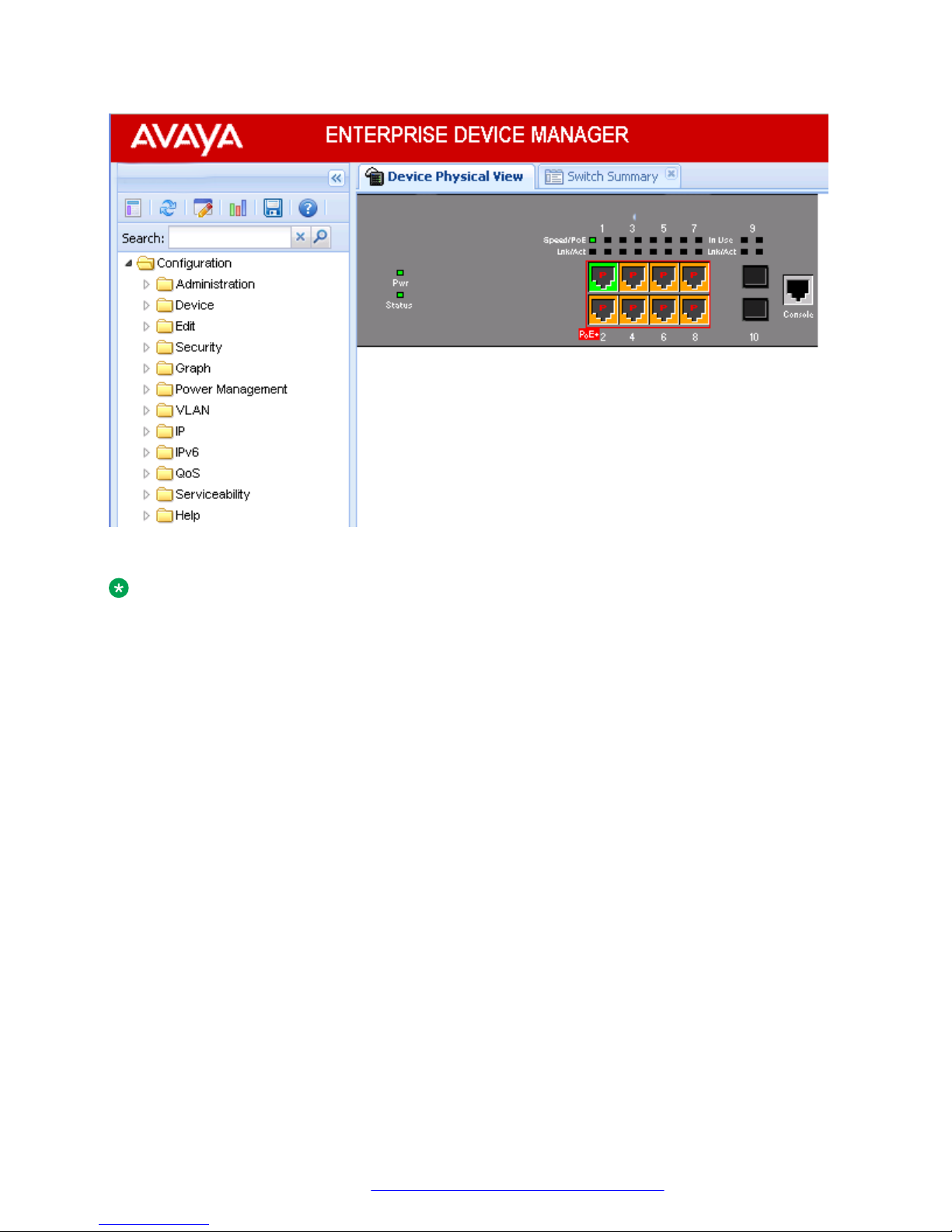
Figure 1: EDM window
Device Physical View
When you access EDM, the first panel in the work area displays a switch summary view. The tab
behind the summary view is a real-time physical view of the front panel of a device or stack called
the Device Physical View.
Objects in the Device Physical View are
• a stand-alone switch, called a unit
• a switch stack, called a chassis
• a port
From the Device Physical View you can
• determine the hardware operating status
• select a switch or a port to perform management tasks on specific objects or view fault,
configuration, and performance information for specific objects
To select an object, click the object. The system outlines the object in yellow, indicating that the
object selected.
The conventions on the device view are similar to the actual switch appearance except that LEDs in
Device Physical View do not blink. The LEDs and the ports are color-coded to reflect hardware
status. Green indicates the port is up and running; red indicates that the port is disabled.
From the menu bar you can click the Device Physical View tab to open the Device Physical View
any time during a session.
September 2016 Quick Start Configuration 12
Comments on this document? [email protected]
Page 13
Enterprise Device Manager
Figure 2: Device Physical View
Note:
Depending on your hardware model, your switch may appear different than the figure shown in
this section.
September 2016 Quick Start Configuration 13
Comments on this document? [email protected]
Page 14

Chapter 4: Connecting to the switch
Connecting a terminal to the switch
This procedure describes the steps to connect a terminal to the console port on the switch.
Before you begin
To use the console port, you need the following equipment:
• Terminal with AC power cord and keyboard. Any terminal or PC with an appropriate terminal
emulator can be used as the management station. For more information, see Quick Install
Guide for Avaya Ethernet Routing Switch 3500 Series, NN47203-300 for a list of the terminal
emulation settings that must be used with any terminal emulation software used to connect to
the switch.
• Use the RJ-45 console cable to connect the switch console port to your management terminal.
The maximum length for the console port cable is 25 feet (8.3 meters).
For more information, see Installing Avaya Ethernet Routing Switch 3500 Series, NN47203–
304 for console port pin-out information. You can use the pin-out information to verify or create
a console cable for use with your maintenance terminal.
Procedure
1. Connect one end of the serial cable to the connector on the terminal or PC.
2. Connect the other end of the serial cable to the console port on the switch.
3. Turn the terminal or PC on.
4. Set the terminal protocol on the terminal or terminal emulation program to VT100 or VT100/
ANSI.
5. Connect to the switch using the terminal or terminal emulation application. The Avaya switch
banner appears when you connect to the switch through the console port.
6. Press Ctrl+Y and type the following CLI commands:
enable
install
The setup utility prompts you to enter the information requested as shown below.
#########################################################################
Welcome to the ERS3500 setup utility.
You will be requested to provide the switch basic connectivity settings.
After entering the requested info, the configuration will be applied and
stored into the switch NVRAM.
September 2016 Quick Start Configuration 14
Comments on this document? [email protected]
Page 15

Configuring with Quick Start using ACLI
Once the basic connectivity settings are applied, additional configuration
can be done using the available management interfaces.
Use Ctrl+C to abort the configuration at any time.
#########################################################################
Please provide the Quick Start VLAN <1-4094> [1]:
Please provide the in-band IP Address[192.168.1.1]:
Please provide the in-band sub-net mask[255.255.255.0]:
Please provide the Default Gateway[0.0.0.0]:
Please provide the Read-Only Community String[**********]:
Please provide the Read-Write Community String[**********]:
Please provide the in-band IPV6 Address/Prefix_length[::/0]:
Please provide the in-band IPV6 Default Gateway[::]:
Do you want to enable the DHCP server? y/n [n]:
#########################################################################
Basic stack parameters have now been configured and saved.
#########################################################################
Configuring with Quick Start using ACLI
The Install script consists of a series of prompts that are used to set up the minimum
configuration information.
You must enter the following information when prompted:
• IP address
• Subnet mask
• Default gateway
• Read-only community string
• Read-write community string
• Quick start VLAN
• IPV6 address/prefix
• IPV6 default gateway
• DHCP server information (optional)
Before you begin
• Connect to the switch using the terminal or terminal emulation application.
Procedure
1. Press
CTRL + Y to obtain a CLI prompt.
2. Enter enable
September 2016 Quick Start Configuration 15
Comments on this document? [email protected]
Page 16

Connecting to the switch
3. Enter install
The switch setup utility banner appears.
4. Enter VLAN ID for the Quick Start at the following prompt:
Please provide the Quick Start VLAN <1–4094> [1]:
5. Enter the IP address at the following prompt:
Please provide the in-band IP Address [192.168.10.6]:
6. Enter the sub-net mask address at the following prompt:
Please provide the in-band sub-net mask [255.255.255.0]:
7. Enter the default gateway IP address at the following prompt:
Please provide the Default Gateway [0.0.0.0]:
8. Enter the read only community string at the following prompt:
Please provide the Read-Only Community String [**********]:
9. Enter the read write community string at the following prompt:
Please provide the Read-Write Community String [**********]:
10. Enter the in-band IPv6 address at the following prompt:
Please provide the in-band IPV6 Address/Prefix_length [ : :/0]:
11. Enter the in-band IPv6 default gateway at the following prompt:
Please provide the in-band IPV6 Default Gateway [ : :]:
12. At the Do you want to enable the DHCP server? prompt, enter Y to enable the
DHCP server, OR leave the prompt at N if you do not want to enable the DHCP server.
Successful completion displays the following message: Basic stack parameters have
now been configured and saved.
Example
###############################################################################
Welcome to the ERS3500 setup utility.
You will be requested to provide the switch basic connectivity settings.
After entering the requested info, the configuration will be applied and
stored into the switch NVRAM.
Once the basic connectivity settings are applied, additional configuration
can be done using the available management interfaces.
Use Ctrl+C to abort the configuration at any time.
###############################################################################
Please provide the Quick Start VLAN <1-4094> [1]:
Please provide the in-band IP Address[192.168.10.6]:
Please provide the in-band sub-net mask [255.255.255.0]:
Please provide the Default Gateway[0.0.0.0]:
Please provide the Read-Only Community String[**********]:
Please provide the Read-Write Community String[**********]:
Please provide the in-band IPV6 Address/Prefix_length[::/0]:
September 2016 Quick Start Configuration 16
Comments on this document? [email protected]
Page 17

Configuring Quick Start using EDM
Please provide the in-band IPV6 Default Gateway[::]:
Do you want to enable the DHCP server? y/n [n]:
###############################################################################
Basic stack parameters have now been configured and saved.
###############################################################################
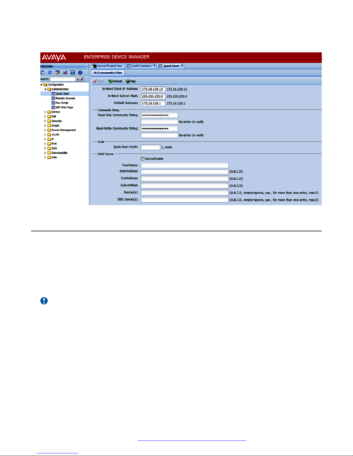
Configuring Quick Start using EDM
Perform this procedure to configure Quick Start to enter the setup mode through a single screen.
Procedure
1. From the navigation tree, click Administration.
2. In the Administration Tree, click Quick Start.
3. In the In-Band Switch IP address, type a switch address.
4. In the In-Band Subnet Mask dialog box, type a subnet mask.
5. In the Default Gateway dialog box, type an IP address.
6. In the Read-Only Community String box, type a character string.
7. In the Re-enter to verify dialog box immediately following the Read-Only Community String
box, retype the character string from Step 6.
8. In the Read-Write Community String dialog box, type a character string.
9. In the Re-enter to verify dialog box immediately following the Read-Write Community String
box, retype the character string from Step 8.
10. In the Quick Start VLAN dialog box, type a VLAN ID.
11. To enable the DHCP Server, select the ServerEnablecheck box and enter the DHCP server
information.
12. Click Apply.
September 2016 Quick Start Configuration 17
Comments on this document? [email protected]
Page 18
Connecting to the switch
Example
Configuring the terminal
You can configure the switch terminal settings to suit your preferences for the terminal speed and
display.
About this task
Use the following procedure to configure terminal settings including the terminal connection speed,
and terminal display width and length, in number of characters.
Important:
After you modify the terminal configuration, the new settings are applied to the current active
session and to all future sessions (serial, telnet or SSH). Terminal configuration change does
not affect open concurrent sessions.
Procedure
1. Log on to ACLI to enter User EXEC mode.
2. At the command prompt, enter the following command:
terminal {speed <2400 | 4800 | 9600 | 19200 | 38400> | length <1–
132> | width <1–132>}
3. To display the current serial port information, enter the following command:
September 2016 Quick Start Configuration 18
Comments on this document? [email protected]
Page 19
BootP automatic IP configuration and MAC address
show terminal
Example
The following example shows the output from the show terminal command.
Switch#show terminal
Terminal speed: 9600
Terminal width: 79
Terminal length: 24
Variable definitions
The following table describes the parameters for the terminal command.
Variable Value
speed {2400|4800|9600|19200|38400} Sets the transmit and receive baud rates for the
terminal. You can set the speed to one of the five
options shown.
DEFAULT: 9600
length <1–132> Sets the length of the terminal display in characters.
RANGE: 1 to 132
DEFAULT: 24
width <1–132> Sets the width of the terminal display in characters.
RANGE: 1 to 132
DEFAULT: 79
BootP automatic IP configuration and MAC address
The switch supports the Bootstrap protocol (BootP). You can use BootP to retrieve an ASCII
configuration file name and configuration server address. With a properly configured BootP server,
the switch automatically learns its assigned IP address, its subnet mask, and the IP address of the
default router (default gateway).
The switch has a unique 48-bit hardware address, or MAC address, that is printed on a label on the
back panel. Use this MAC address when you configure the network BootP server to recognize the
switch BootP requests.
The BootP modes supported by the switch are:
• BootP or Last Address mode
• BootP or Default IP
• BootP Always
• BootP Disabled
September 2016 Quick Start Configuration 19
Comments on this document? [email protected]
Page 20

Connecting to the switch
Important:
Whenever the switch is broadcasting BootP requests, the BootP process eventually times out if
a reply is not received. When the process times out, the BootP request mode automatically
changes to BootP or Default IP mode. To restart the BootP process, change the BootP request
mode to any of the following modes:
• Always
• Disabled
• Last
• Default-ip
Setting user access limits using ACLI
The administrator can use ACLI to limit user access by creating and maintaining passwords for web,
telnet, and console access. This is a two-step process that requires that you first create the
password and then enable it.
Setting the system user name and password using ACLI
Use the following procedure to configure the system user name and password for access through
the serial console port and Telnet. This procedure supports only one read-only and one read-write
user on the switch.
Procedure
1. Enter Global Configuration mode:
enable
configure terminal
2. At the command prompt, enter the following command:
username <username> <password> [<ro | rw>]
3. To set the username and password to the system default settings, enter the following
command:
default username [<ro | rw>]
Note:
After you configure the user name and password with the username command, you
can update the password without changing the username by using the cli password
command, the console interface, or EDM.
September 2016 Quick Start Configuration 20
Comments on this document? [email protected]
Page 21
Setting user access limits using ACLI
Variable definitions
The following table describes the parameters for the username command.
Variable Definition
<username> <password> Enter your user name for the first variable, and your
password for the second variable. The default user
name values are RO for read-only access and RW
for read/write access.
ro|rw Specifies that you are modifying the read-only (ro)
user name or the read-write (rw) user name. The
ro/rw variable is optional. If it is omitted, the
command applies to the read-only mode.
Enabling and disabling passwords
After you set the read-only and read-write passwords, you can individually enable or disable them
for the various switch-access methods.
Procedure
1. Enter Global Configuration mode:
enable
configure terminal
2. Enter the following commands to configure the password for selected access or a specific
authentication type:
cli password {telnet | serial} {none | local | radius | tacacs}
cli password {read-only | read-write} [<password>]
Variable definitions
The following table describes the parameters for the cli password command.
Variable Definition
read-only | read-write Modifies the read only password or the read/write
password.
<password> Specifies the password.
Important:
This parameter is not available when Password
Security is enabled, in which case the switch
prompts you to enter and confirm the new
password. For information about password
security, see Configuring Security on Avaya
Table continues…
September 2016 Quick Start Configuration 21
Comments on this document? [email protected]
Page 22
Connecting to the switch
Variable Definition
Ethernet Routing Switch 3500 Series,
NN47203-504.
serial | telnet Modify the password for serial console access or for
Telnet access.
none | local | radius | tacacs Indicates the password type being modified:
• none: disable the password
• local: uses the locally defined password for serial
console or Telnet access
• radius: uses RADIUS authentication for serial
console or Telnet access
• tacacs: uses TACACS+ authentication,
authorization, and accounting (AAA) services for
serial console or Telnet access
Setting user access limits using Enterprise Device
Manager
You can use Enterprise Device Manager (EDM) to limit user access by creating and maintaining
passwords for web, telnet, and console access.
Configuring a console password using EDM
Use this procedure to configure a Console password for an individual switch.
Procedure
1. From the navigation tree, double-click Security to open the Security tree.
2. From the Security tree, click Web/Telnet/Console.
3. In the work area, click the Console Password tab.
4. In the Console Switch Password Setting, select a value from the Console Password Type
list.
5. In the Read-Only Switch Password dialog box, type a character string.
6. In the Re-enter to verify dialog box for the Read-Only Switch Password, retype the
character string.
7. In the Read-Write Switch Password dialog box, type a character string.
September 2016 Quick Start Configuration 22
Comments on this document? [email protected]
Page 23

Setting user access limits using Enterprise Device Manager
8. In the Re-enter to verify dialog box for the Read-Write Switch Password, retype the
character string.
9. On the toolbar, click Apply.
Field descriptions
Use the descriptions in the following table to configure the console switch password.
Variable Definition
Console Stack Password Type Specify the type of password to use. Values include:
• none—Disables the password
• Local Password—Use the locally-defined
password for serial console access
• RADIUS Authentication—Use RADIUS
authentication for serial console access
• TACACS Authentication—Use TACACS+
authentication, authorization and accounting (AAA)
services authentication for console access
Read-Only Stack Password Specify the read-only password for stack or switch
access.
Read-Write Stack Password Specify the read-write password for stack or switch
access.
Configuring a Web and Telnet password using EDM
Use this procedure to configure a Web and Telnet password for an individual switch.
Procedure
1. From the navigation tree, double-click Security to open the Security tree.
2. In the Security tree, double-click Web/Telnet/Console.
3. In the work area, click the Web/Telnet Password tab.
4. In the Web/Telnet Switch Password Setting, select a value from the Web/Telnet Switch
Password Type list.
5. In the Read-Only Switch Password dialog box, type a character string.
6. In the Re-enter to verify dialog box for the Read-Only Switch Password, retype the
character string.
7. In the Read-Write Switch Password dialog box, type a character string.
8. In the Re-enter to verify dialog box for the Read-Write Switch Password, retype the
character string
9. On the toolbar, click Apply.
September 2016 Quick Start Configuration 23
Comments on this document? [email protected]
Page 24

Connecting to the switch
Field descriptions
Use the descriptions in the following table to configure the console switch password.
Variable Definition
Web/Telnet Stack Password Type Specify the type of password to use. Values include:
• none—Disables the password
• Local Password—Use the locally-defined
password for serial console access
• RADIUS Authentication—Use RADIUS
authentication for serial console access
• TACACS Authentication—Use TACACS+
authentication, authorization and accounting (AAA)
services authentication for console access
Read-Only Stack Password Specify the read-only password for stack or switch
access. The maximum length of the password is 15
characters.
Read-Write Stack Password Specify the read-write password for stack or switch
access. The maximum length of the password is 15
characters.
Configuring a console password using EDM
Use this procedure to configure a Console password for an individual switch.
Procedure
1. From the navigation tree, double-click Security to open the Security tree.
2. From the Security tree, click Web/Telnet/Console.
3. In the work area, click the Console Password tab.
4. In the Console Switch Password Setting, select a value from the Console Password Type
list.
5. In the Read-Only Switch Password dialog box, type a character string.
6. In the Re-enter to verify dialog box for the Read-Only Switch Password, retype the
character string.
7. In the Read-Write Switch Password dialog box, type a character string.
8. In the Re-enter to verify dialog box for the Read-Write Switch Password, retype the
character string.
9. On the toolbar, click Apply.
September 2016 Quick Start Configuration 24
Comments on this document? [email protected]
Page 25

Configuring a Web and Telnet password using EDM
Field descriptions
Use the descriptions in the following table to configure the console switch password.
Variable Definition
Console Stack Password Type Specify the type of password to use. Values include:
• none—Disables the password
• Local Password—Use the locally-defined
password for serial console access
• RADIUS Authentication—Use RADIUS
authentication for serial console access
• TACACS Authentication—Use TACACS+
authentication, authorization and accounting (AAA)
services authentication for console access
Read-Only Stack Password Specify the read-only password for stack or switch
access.
Read-Write Stack Password Specify the read-write password for stack or switch
access.
Configuring a Web and Telnet password using EDM
Use this procedure to configure a Web and Telnet password for an individual switch.
Procedure
1. From the navigation tree, double-click Security to open the Security tree.
2. In the Security tree, double-click Web/Telnet/Console.
3. In the work area, click the Web/Telnet Password tab.
4. In the Web/Telnet Switch Password Setting, select a value from the Web/Telnet Switch
Password Type list.
5. In the Read-Only Switch Password dialog box, type a character string.
6. In the Re-enter to verify dialog box for the Read-Only Switch Password, retype the
character string.
7. In the Read-Write Switch Password dialog box, type a character string.
8. In the Re-enter to verify dialog box for the Read-Write Switch Password, retype the
character string
9. On the toolbar, click Apply.
September 2016 Quick Start Configuration 25
Comments on this document? [email protected]
Page 26

Connecting to the switch
Field descriptions
Use the descriptions in the following table to configure the console switch password.
Variable Definition
Web/Telnet Stack Password Type Specify the type of password to use. Values include:
• none—Disables the password
• Local Password—Use the locally-defined
password for serial console access
• RADIUS Authentication—Use RADIUS
authentication for serial console access
• TACACS Authentication—Use TACACS+
authentication, authorization and accounting (AAA)
services authentication for console access
Read-Only Stack Password Specify the read-only password for stack or switch
access. The maximum length of the password is 15
characters.
Read-Write Stack Password Specify the read-write password for stack or switch
access. The maximum length of the password is 15
characters.
Customizing the opening banner
You can customize the banner that appears when you connect to the switch. You can customize the
text that reads AVAYA. However you cannot customize the second line that reads Enter [Ctrl]
+y to begin.
The Banner Control feature provides an option to specify the banner text. If you choose not to
display the banner, the system enters the ACLI command mode through the default command
interface. You do not have to press the Ctrl+y keys.
The Banner display that you select is used for subsequent console sessions. For executing the new
mode in the console, you must logout. For Telnet access, all subsequent sessions use the selected
mode.
Customizing the opening ACLI banner
Specifies the banner displayed at startup; either static or custom.
Procedure
1. Enter Global Configuration mode:
September 2016 Quick Start Configuration 26
Comments on this document? [email protected]
Page 27
Customizing the opening banner
enable
configure terminal
2. At the command prompt, enter the following command:
[no] banner [custom | static | disabled | <1–19> LINE ]
Variable definitions
The following table describes the parameters for the banner command.
Variable Value
static Displays the default agent-banner
custom Displays the custom agent-banner
disabled Skips the agent-banner display
<1–19> LINE Fills the Nth line of the custom banner (1<N<19) with
the text specified in LINE
no Clears all lines of a previously stored custom banner
Displaying the current banner
Display the current banner.
Procedure
1. Enter Global Configuration mode:
enable
configure terminal
2. At the command prompt, enter the following command:
show banner [custom | static]
Variable definitions
The following table describes the parameters for the show banner command.
Variable
static Displays default banner
custom Displays custom banner
(if empty) Displays static, custom or disabled status if
Value
parameter is not entered
September 2016 Quick Start Configuration 27
Comments on this document? [email protected]
Page 28
Connecting to the switch
Configuring Simple Network Time Protocol
The Simple Network Time Protocol (SNTP) feature synchronizes the Universal Coordinated Time
(UTC) to an accuracy within 1 second. This feature adheres to the IEEE RFC 2030 (MIB is the
s5agent). With this feature, the system can obtain the time from any RFC 2030-compliant NTP/
SNTP server.
For more information on SNTP, see Configuring Systems on Avaya Ethernet Routing Switch 3500
Series, NN47203–506.
Procedure
1. Enter Global Configuration mode:
enable
configure terminal
2. Enter the following command:
[no] sntp server <primary | secondary> address <A.B.C.D>
Variable definitions
Use the data in the following table to use the sntp server command.
Variable Definition
<A.B.C.D> Specifies the IP address of the primary or secondary
NTP server in the format XXX.XXX.XXX.XXX.
Configuring local time zone
Configure the time zone to use an internal system clock to maintain accurate time. The time zone
data does not include daylight saving time changes. You must configure daylight saving time.
Note:
SNTP uses Universal Coordinated Time UTC for all time synchronizations so it is not affected
by different time zones.
Procedure
1. Enter Global Configuration mode:
enable
configure terminal
2. At the command prompt, enter the following command:
September 2016 Quick Start Configuration 28
Comments on this document? [email protected]
Page 29
Configuring daylight savings time
[no] clock time-zone <zone> <hours> <minutes>
Variable definitions
The following table describes the parameters for the clock time-zone command.
Variable Value
zone Specifies time zone acronym that can be displayed
when showing system time; for example, EST for
Eastern Standard Time.
RANGE: Up to 4 characters
hours Specify the hours difference from UTC.
RANGE: —12 to + 12
minutes Optional minutes difference from UTC.
RANGE: 0–59
no Disables the clock time zone feature
Configuring daylight savings time
Configure the daylight savings time with start and end dates, or disable the daylight savings time
feature.
Procedure
1. Enter Global Configuration mode:
enable
configure terminal
2. At the command prompt, enter the following command:
[no] clock summer-time <zone> [date {<day> <month> <year> <hh:mm>}
{<day> <month> <year> <hh:mm>}] [<offset>]
Variable definitions
The following table describes the parameters for the clock summer-time command.
September 2016 Quick Start Configuration 29
Comments on this document? [email protected]
Page 30
Connecting to the switch
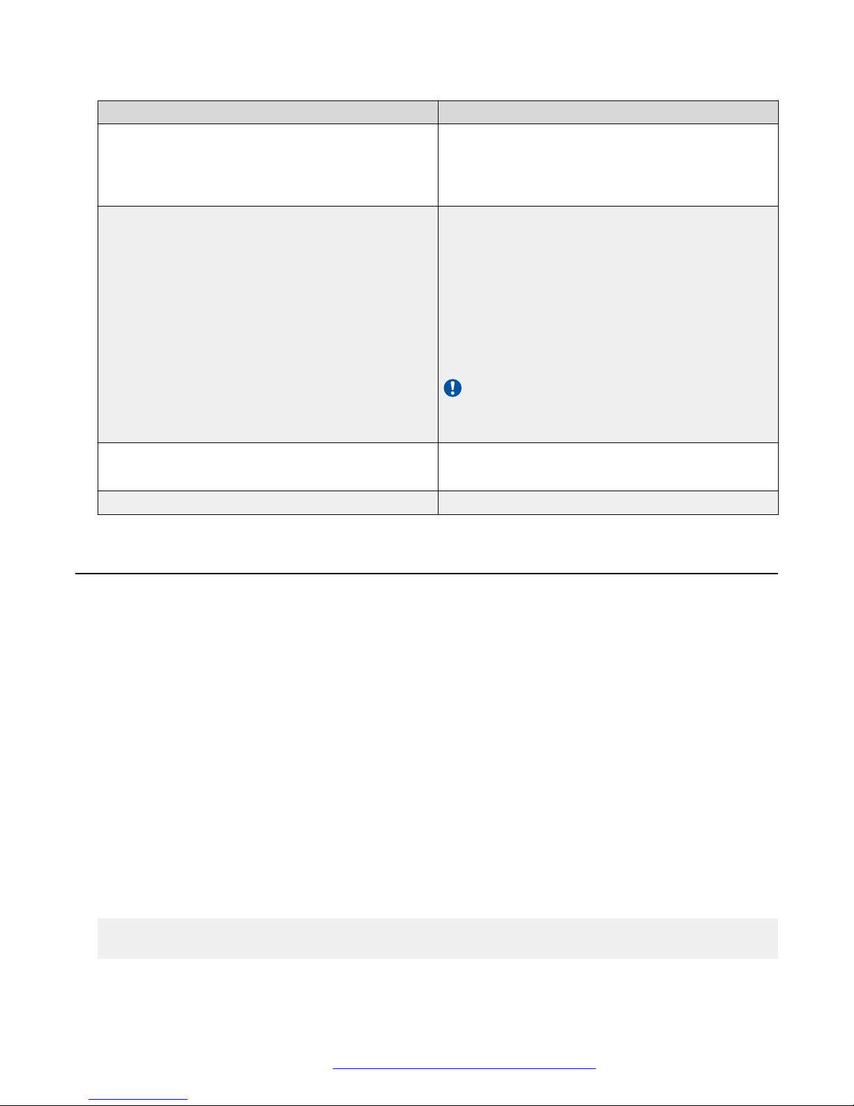
Variable Value
zone Specifies the acronym to be displayed when summer
time is in effect. If unspecified, defaults to the time
zone acronym.
RANGE: up to 4 characters
date {<day> <month> <year> <hh:mm>} {<day>
<month> <year> <hh:mm>}
offset Number of minutes to add during summer time
The first date specifies when summer time starts,
and the second date specifies when summer time
ends.
• day — day of the month (RANGE: 1 to 31)
• month — month (RANGE: first three letters by
name)
• hh:mm — time in military format (24–hour clock), in
hours and minutes
Important:
<day> <month> parameters can also be
entered in order: <month> <day>.
RANGE: —840 to 840
no Disables the daylight savings time feature
Specifying summer-time recurring dates
Specify the dates that recur during the summer-time clock every year. This procedure provides
flexibility for countries where the Daylight Savings Time is different than North America.
Procedure
1. Enter Global Configuration mode:
enable
configure terminal
2. At the command prompt, enter the following command:
clock summer-time recurring <1–5> <DAY> <MONTH> hh:mm> <1–5> <DAY>
<MONTH> <hh:mm> <1–1440>
Example
The following figure provides a sample of the output of the clock summer-time recurring
command.
Switch(config)#clock summer-time recurring 1 tues Jun 12:01 3 sat Sep 23:57 1
Summer time recurring is set to:
start: 1st week of June on Tuesday at 12:01
September 2016 Quick Start Configuration 30
Comments on this document? [email protected]
Page 31
Displaying the local time zone settings
end: 3rd week of September on Saturday at 23:57
Offset: 60 minutes.
Variable definitions
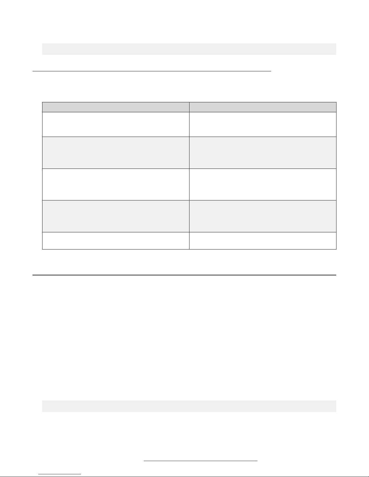
The following table describes the parameters for the summer-time recurring command.
Variable Value
<1–5> Specifies the week of the month. The first
occurrence specifies when the recurring starts, and
the second specifies when the recurring stops.
<DAY> Specifies the day of the week as the first 3 letters of
the name. The first occurrence specifies when the
recurring starts, and the second specifies when the
recurring stops.
<MONTH> Specifies the Month using the first 3 letters of the
name. The first occurrence specifies when the
recurring starts, and the second specifies when the
recurring stops.
<hh:mm> Specifies the time in hours and minutes in military
format (24–hr). The first occurrence specifies when
the recurring starts, and the second specifies when
the recurring stops.
<1–1440> Specifies the number of minutes to add or subtract
during summer-time recurring.
Displaying the local time zone settings
Display the settings for the local time zone.
Procedure
1. Enter Global Configuration mode:
enable
configure terminal
2. At the command prompt, enter the following command:
show clock time-zone
Example
The following figure provides a sample of the output of the show clock time-zone command.
switch(config)#show clock time-zone
Time zone offset from UTC is 00:00
September 2016 Quick Start Configuration 31
Comments on this document? [email protected]
Page 32

Connecting to the switch
Displaying the daylight savings time settings
Display the daylight savings time settings.
Procedure
1. Enter Global Configuration mode:
enable
configure terminal
2. At the command prompt, enter the following command:
show clock summer-time
Example
The following figure provides a sample of the output of the show clock summer-time
command.
switch(config)#show clock summer-time
Summer time recurring is set to:
start: on Tuesday in the 1st week of June at 12:01
end: on Saturday in the 3rd week of September at 23:59
Offset: 60 minutes.
Daylight saving time is disabled
Configuring a static route using ACLI
Create static routes to manually configure a path to destination IP address prefixes.
Before you begin
• Enable IP routing globally.
• Enable IP routing and configure an IP address on the VLANs to be routed.
Procedure
1. Log on to ACLI in Global Configuration command mode.
2. At the command prompt, enter the following command:
[no] ip route <dest-ip> <mask> <next-hop> [<cost>] [disable]
[enable] [weight <cost>]
Variable definitions
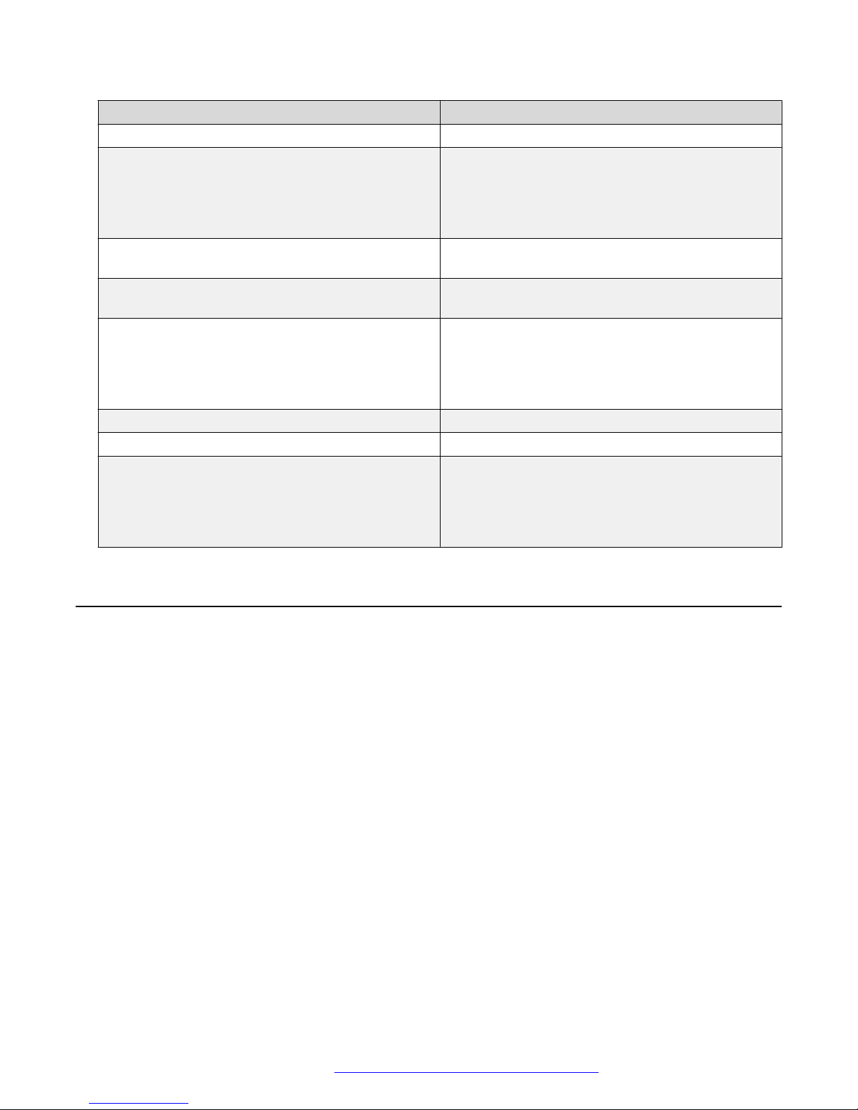
The following table describes the parameters for the ip route command.
September 2016 Quick Start Configuration 32
Comments on this document? [email protected]
Page 33
Enabling remote access
Variable Value
[no] Removes the specified static route.
<dest-ip> Specifies the destination IP address for the route
being added.
DEFAULT:
0.0.0.0 is considered the default route.
<mask> Specifies the destination subnet mask for the route
being added.
<next-hop> Specifies the next hop IP address for the route being
added.
[<cost>] Specifies the weight, or cost, of the route being
added.
RANGE:
1–65535
[enable] Enables the specified static route.
[disable] Disables the specified static route.
[weight<cost>] Changes the weight, or cost, of an existing static
route.
RANGE:
1–65535
Enabling remote access
You can enable remote access for telnet, SSH (on SSH software images), SNMP, and webpage
access.
For more information, see Using ACLI and EDM on Avaya Ethernet Routing Switch 3500 Series,
NN47203-102 and Configuring Systems on Avaya Ethernet Routing Switch 3500 Series, NN47203–
506.
About this task
Use the following procedure to enable and configure remote access to the management features of
the switch.
Procedure
1. Enter Global Configuration mode:
enable
configure terminal
2. To enable telnet remote access, enter the following command:
September 2016 Quick Start Configuration 33
Comments on this document? [email protected]
Page 34

Connecting to the switch
telnet-access enable
3. To enable SSH remote access, enter the following command:
ssh
4. To enable SNMP remote access, enter the following command:
snmp-server enable
5. To enable webpage remote access, enter the following command:
web-server enable
Example
The following is an example of enabling telnet remote access:
Switch>enable
Switch#configure terminal
Enter configuration commands, one per line. End with CNTL/Z.
Switch(config)#telnet-access enable
Switch(config)#
Using telnet to log on to the device
Procedure
1. From a computer or terminal, start a telnet session:
telnet <IPv4_address>
where <IPv4_address> is the IP address of the switch. The stand-alone units use the default
IP address of 192.168.1.1 and the stacking units use the default IP address of 192.168.1.2 if
the switch does not obtain its IP address from another source.
2. Enter the user ID and password when prompted.
Enabling the web server management interface
The web server must be enabled to access Enterprise Device manager (EDM). If you do not want
EDM to be accessible on the device, disable the web server. By default, the web server is enabled.
Procedure
1. Enter Global Configuration mode:
enable
configure terminal
2. At the command prompt, enter the following command:
September 2016 Quick Start Configuration 34
Comments on this document? [email protected]
Page 35

Accessing the switch through the web interface
web-server enable
Accessing the switch through the web interface
You can use EDM to configure and maintain your switch through a web-based graphical user
interface. You can monitor the switch through a web browser from anywhere on the network.
By default, you can access the web interface using Hypertext Transfer Protocol Secure (HTTPS)
only.
For more information about configuring the web server to respond to HTTPS only or to both HTTPS
and Hypertext Transfer Protocol (HTTP) client browser requests, see Configuring Security on Avaya
Ethernet Routing Switch 3500 Series, NN47203-504.
By default, the web interface uses a 15 minute time-out period. If no activity occurs for 15 minutes,
the system logs off the switch web interface, and you must reenter the password information.
To configure inactivity time-out, see Configuring Security on Avaya Ethernet Routing Switch 3500
Series, NN47203-504.
Before you begin
• Ensure that the switch is running.
• Note the switch IP address.
• Ensure that the web server is enabled.
• Note the user name and password.
• Open one of the supported web browsers.
For more information about the supported browsers, see Using ACLI and EDM on Avaya
Ethernet Routing Switch 3500 Series, NN47203-102.
About this task
Use this procedure to access the switch through a web browser.
Procedure
1. Start your web browser.
2. Type the switch IP address as the URL in the Web address field.
http://<IP Address>
OR
https://<IP Address>
3. Enter the user name.
4. Enter the password.
5. Click Log On.
September 2016 Quick Start Configuration 35
Comments on this document? [email protected]
Page 36
Connecting to the switch
Creating a VLAN using ACLI
Use this procedure to create port-based or IPv6 protocol-based VLANs.
Important:
This procedure fails if the VLAN already exists.
Procedure
1. Enter Global Configuration mode:
enable
configure terminal
2. At the command prompt, enter the following command:
vlan create {<1–4094> | <vid_list>} [name <WORD>] [ type { port |
protocol-ipv6Ether2 | voice-vlan}] | [voice-vlan] [msti <1–7> |
cist]
Example
vlan create 2-10,80 type port
vlan create 15 type voice-vlan
Variable definitions
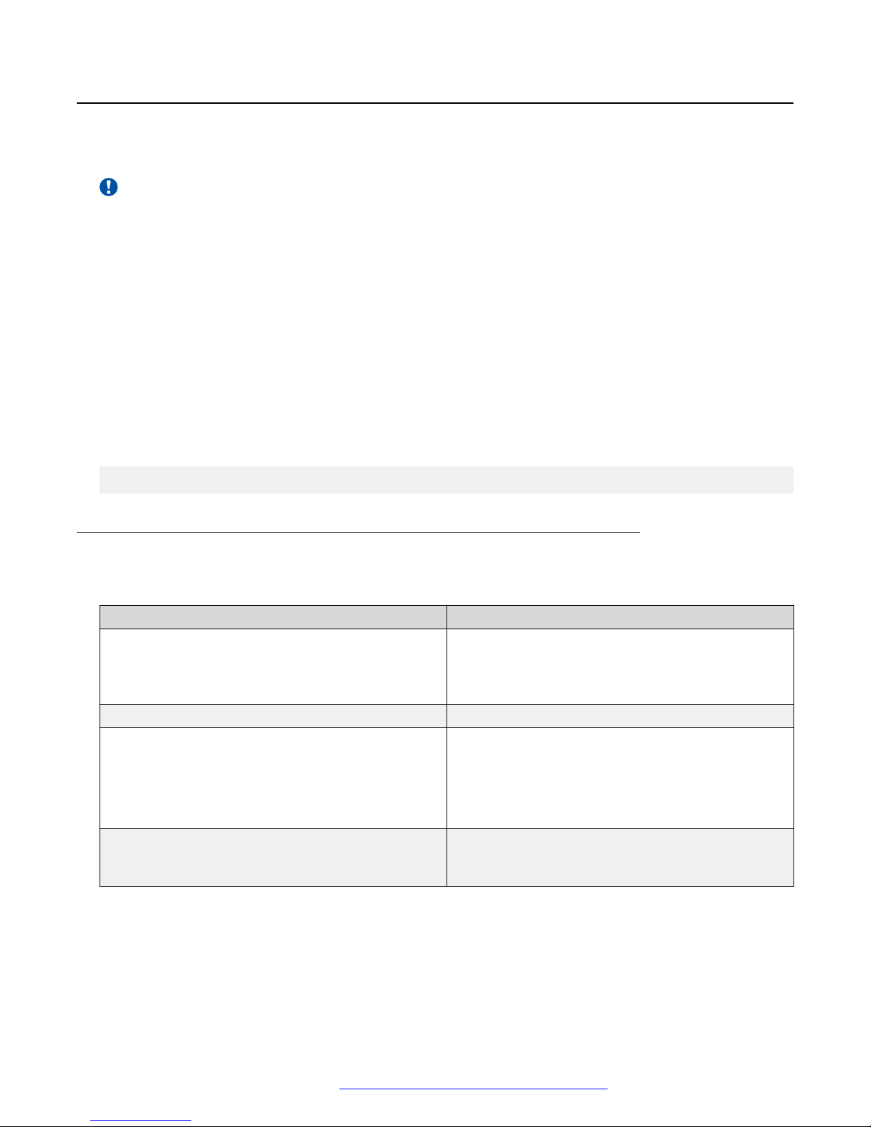
The following table describes the parameters for the vlan create command.
Variable
<1–4094> | <vid_list> Enter the ID of the VLAN you want to create or enter
name <WORD> Enter the new name you want for the VLAN.
type Enter the type of VLAN. Values include:
msti <1–7> | cist This parameter is available only in MSTP mode. It
Value
as a list or range of VLAN IDs to create multiple
VLANs simultaneously. A VLAN ID can range from 1
to 4094..
• port — port-based VLAN
• protocol-ipv6Ether2 — IPv6 protocol-based VLAN
• voice-vlan — voice VLAN
associates the VLAN with either an MSTI instance or
the CIST.
September 2016 Quick Start Configuration 36
Comments on this document? [email protected]
Page 37

Saving the configuration
Saving the configuration
After you change the configuration, you must save the changes. Save the configuration to a file to
retain the configuration settings.
Note:
File Transfer Protocol (FTP) and TFTP support both IPv4 and IPv6 addresses, with no
difference in functionality or configuration.
Before you begin
Enable the Trivial File Transfer Protocol (TFTP) on the switch.
About this task
Use this procedure to save the configuration.
Procedure
1. Enter Privileged EXEC mode:
enable
2. At the command prompt, enter the following command:
save config
Configuring system identification
About this task
You can configure system identification to specify the system name, contact person, and location of
the switch, and to add a trap receiver to the trap-receiver table.
Procedure
1. Enter Global Configuration mode:
enable
configure terminal
2. Enable the Simple Network Management Protocol (SNMP) server:
snmp-server enable
3. Configure the read-only community name:
snmp-server community ro
Note:
Enter the community string twice.
September 2016 Quick Start Configuration 37
Comments on this document? [email protected]
Page 38

Connecting to the switch
If you ran the install script to set up the configuration information, the read-only
community name is already configured.
4. Configure the read-write community name:
snmp-server community rw
Note:
Enter the community string twice.
If you ran the install script to set up the configuration information, the read-write
community name is already configured.
5. Configure the system name:
snmp-server name <text>
6. Configure the system contact:
snmp-server contact <text>
7. Configure the location:
snmp-server location <text>
8. Configure the SNMP host to add a trap receiver to the trap-receiver table:
snmp-server host <host-ip> <community-string>
Variable definitions
Use the definitions in the following table to use the snmp-server name command.
Table 1: snmp-server name command
Variable Definition
<text> Specify the SNMP system name value. Enter an
alphanumeric string of up to 255 characters.
Note:
On the console, the SNMP server name is
truncated. On the web interface, the full SNMP
server name appears.
Use the definitions in the following table to use the snmp-server contact command.
Table 2: snmp-server contact command
Variable Definition
<text> Specify the SNMP system contact value. Enter an
September 2016 Quick Start Configuration 38
ASCII string of up to 255 characters.
Comments on this document? [email protected]
Page 39
Configuring system identification
Use the definitions in the following table to use the snmp-server location command.
Table 3: snmp-server location command
Variable Definition
<text> Specify the SNMP system location value. Enter an
alphanumeric string of up to 255 characters.
Use the definitions in the following table to use the snmp-server host command.
Table 4: snmp-server host command
Variable Definition
<host-ip> Specify an IPv4 or IPv6 address for a host intended
to be the trap destination.
<community-string> If you are using the proprietary method for SNMP,
enter a community string that works as a password
and permits access to the SNMP protocol.
September 2016 Quick Start Configuration 39
Comments on this document? [email protected]
Page 40
Chapter 5: Configuring the switch using
ACLI
Configuring the IP address
Use this procedure to configure the IP address and subnet mask for the switch or stack. You can
also use this procedure to select the boot mode for the next switch reboot.
Important:
When you change the IP address or subnet mask, you can lose connection to Telnet and the
Web. You also disable any new Telnet connection, and you must connect to the serial Console
port to configure a new IP address.
Note:
If you do not specify the stack or switch parameter, the system automatically modifies the stack
IP address when in stack mode and modifies the switch IP address when in standalone mode.
Procedure
1. Enter Global Configuration mode:
enable
configure terminal
2. At the command prompt, enter the following command:
ip address [switch|stack|unit<1–8>][<A.B.C.D>] [netmask <A.B.C.D>]
[default-gateway <A.B.C.D>]
Variable definitions
The following table describes the parameters for the ip address command.
Variable
A.B.C.D Enters the IP address or subnet mask of the switch
Value
in the format XXX.XXX.XXX.XXX; netmask is
optional.
Table continues…
September 2016 Quick Start Configuration 40
Comments on this document? [email protected]
Page 41
Configuring the IP address
Variable Value
switch | stack | unit <1–8> Specifies whether to set the IP address for the
switch, the stack, or another unit in a stack.
netmask Sets the IP subnet mask.
default-gateway <A.B.C.D> Sets the IP address of the default gateway.
Configuring the IP address
Use this procedure to automatically obtain an in-band management IP address, subnet mask and
default gateway on the switch or stack.
About this task
When you use DHCP, the switch or stack can also obtain up to three DNS server IP addresses.
Procedure
1. Enter Global Configuration mode:
enable
configure terminal
2. At the command prompt, enter the following command:
ip address source {bootp-always | bootp-last-address | bootp-whenneeded | configured-address | dhcp-always | dhcp-last-address |
dhcp-when-needed}
Variable definitions
The following table describes the parameters for the ip address sourcecommand.
Variable
bootp-always Always use the BootP server.
bootp-last-address Use the last BootP server.
bootp-when-needed Use the BootP server when needed.
configured-address Use the manually configured IP configuration.
dhcp-always Always use the DHCP server.
dhcp-last-address Use the last DHCP server.
dhcp-when-needed Use DHCP client when needed.
Value
DEFAULT: bootp-when-needed
September 2016 Quick Start Configuration 41
Comments on this document? [email protected]
Page 42

Configuring the switch using ACLI
Clearing the IP address
Use this procedure to clear the existing IP address and subnet mask for the switch or stack or
another unit of a stack.
Important:
When you change the IP address or subnet mask, you can lose connection to Telnet and the
Web. You also disable any new Telnet connection, and you must connect to the serial Console
port to configure a new IP address.
Procedure
1. Enter Global Configuration mode:
enable
configure terminal
2. At the command prompt, enter the following command:
no ip address [switch|stack|unit<1–8>]
Configuring the IP address to the default value
The default value for the switch is 192.168.1.1 for Standalone Mode or 192.168.1.2 for Stacking
Mode.
Procedure
1. Enter Global Configuration mode:
enable
configure terminal
2. At the command prompt, enter the following command:
default ip address
Displaying IP address information
Use this procedure to display IP configurations, switch address, subnet mask, and gateway address.
Procedure
1. Log on to ACLI to enter User EXEC mode.
2. At the command prompt, enter the following command:
September 2016 Quick Start Configuration 42
Comments on this document? [email protected]
Page 43
Changing subnet netmask value
show ip address
Example
The following figure displays a sample output for the show ip address command.
Switch>show ip address
Configured In Use Last BootP/DHCP
------------- ------------- --------------Stack IP Address: 172.16.120.10 0.0.0.0
Switch IP Address: 172.16.120.12 172.16.120.12 0.0.0.0
Switch Subnet Mask: 255.255.255.0 255.255.255.0 0.0.0.0
Note:
The Router and DNS IP addresses are global, or common. Addresses and pools that do not
have Router and DNS addresses configured within them use these global addresses.
Changing subnet netmask value
The subnet mask is configured using procedure Configuring the IP address on page 40. Use this
procedure to change the subnet mask to the default value or clear the subnet mask.
Procedure
1. Enter Global Configuration mode:
enable
configure terminal
2. At the command prompt, enter the following command:
[default] [no] ip netmask
Variable definitions
The following table describes the parameters for the ip netmask command.
Variable
default Sets the subnet mask to the default value
no Sets the subnet mask for a switch to all zeros
Value
(255.255.255.0).
(0.0.0.0).
September 2016 Quick Start Configuration 43
Comments on this document? [email protected]
Page 44
Configuring the switch using ACLI
Configuring the default gateway
Use this procedure to configure the IP default gateway address for a switch, to change the IP default
gateway address to the default address, or to clear the IP default gateway address.
Important:
When you change the IP gateway address, you can lose connection to Telnet and the Web. You
also can disable any new Telnet connection required to connect to the serial Console port to
configure a new IP Gateway address.
Procedure
1. Enter Global Configuration mode:
enable
configure terminal
2. At the command prompt, enter the following command:
[no] [default] ip default-gateway <A.B.C.D>
Variable definitions
The following table describes the parameters for the ip default-gateway command.
Variable
<A.B.C.D> Enter the IP address of the default IP gateway in the
no Clears the IP address of the default IP gateway. Sets
default Sets the IP default gateway address to all zeros
Value
format XXX.XXX.XXX.XXX.
DEFAULT: 0.0.0.0.
Important:
When you change the IP gateway, you can lose
connection to Telnet and the Web. You can also
disable any new Telnet connection required to
connect to the serial Console port to configure a
new IP Gateway address.
the IP default gateway address to zeros (0).
(0.0.0.0).
September 2016 Quick Start Configuration 44
Comments on this document? [email protected]
Page 45
Displaying IP configuration
Displaying IP configuration
This procedure is used to display the IP configuration, specifically BootP mode, switch or stack or
unit address, subnet mask, and gateway address. These parameters are displayed for what is
configured, what is in use, and the last BootP.
Procedure
1. Log on to ACLI to enter User EXEC mode.
2. At the command prompt, enter the following command:
show ip [bootp][default-gateway [address [switch | stack | unit <1–
8>]][dns]
If you do not enter any parameters, the show ip command displays all IP-related
configuration information.
Example
The following figure displays a sample output of the show ip command.
Switch>show ip
Bootp/DHCP Mode: BootP Or Default IP
Configured In Use Last BootP/DHCP
------------- ------------- --------------Stack IP Address: 172.16.120.10 0.0.0.0
Switch IP Address: 172.16.120.12 172.16.120.12 0.0.0.0
Switch Subnet Mask: 255.255.255.0 255.255.255.0 0.0.0.0
Default Gateway: 172.16.120.1 172.16.120.1 0.0.0.0
switch>
Variable definitions
The following table describes the parameters for the show ip command.
Variable
bootp mode Displays BootP-related IP information.
default-gateway Displays the IP address of the default gateway.
address Displays the current IP address.
switch | stack | unit <1–8> Specifies the current IP address of the switch or
dns Displays the DNS configuration.
Value
stack or specified unit.
September 2016 Quick Start Configuration 45
Comments on this document? [email protected]
Page 46
Chapter 6: Verification
Verification
Pinging an IP device
You can ping a device to test the connection between a switch and another network device. After
you ping a device, the switch sends an Internet Control Message Protocol (ICMP) packet to the
target device. If the device receives the packet, it sends a ping reply. After the switch receives the
reply, a message appears that indicates traffic can reach the specified IP address. If the switch does
not receive a reply, the message indicates the address does not respond.
Before you begin
The local IP address must be configured before issuing the ping command.
Procedure
1. Log on to ACLI to enter User EXEC mode.
2. At the command prompt, enter the following command:
ping <IP_address>
where <IP_address> is an IPv4 or IPv6 address.
Example
The following figure shows a sample ping response.
Switch>ping 120.16.125.10
Host is reachable
Variable definitions
The following table describes the parameters for the ping command.
Variable
<A.B.C.D > | <dns_host_name> | <WORD> Specifies the IP address, DNS host name, or IPv6
datasize<64–4096> Specifies the size of the ICMP packet to be sent. The
Value
address of the unit to test.
data size range is from 64 to 4096 bytes.
Table continues…
September 2016 Quick Start Configuration 46
Comments on this document? [email protected]
Page 47
Variable Value
{count <1–9999>} | continuous Sets the number of ICMP packets to be sent. The
continuous mode sets the ping running until the user
interrupts it by entering Ctrl-C.
{timeout |-t} <1–120> Sets the timeout using either the timeout or -t
parameter, followed by the number of seconds the
switch must wait before timing out.
interval<1–60> Specifies the number of seconds between
transmitted packets.
debug Provides additional output information such as ICMP
sequence number and trip time.
source<A.B.C.D> Specifies the source IP address of the packet. Must
be a configured address on the switch.
ttl<0–255> Specifies the maximum hop limit for the packet.
Range of 0 to 255.
Variable definitions
Verification
The following table describes the parameters for the show boot command.
Variable
diag Displays information for the diagnostic load only.
image Displays information for the image load only.
Value
Displaying the agent and diagnostic software load
Display the currently loaded and operational software status for agent and diagnostic loads, either
individually or combined, for a switch or stack.
Procedure
1. Log on to ACLI to enter User EXEC mode.
2. At the command prompt, enter the following command:
show boot [diag] [image]
Example
The following figure provides a sample output of the show boot command.
Switch>show boot
Unit Agent Image Active Image Diag Image Active Diag
----- ----------- ------------ ---------- ----------1 5.2.0.037 5.2.0.037 1.0.0.11 1.0.0.11
2 5.2.0.037 5.2.0.037 1.0.0.11 1.0.0.11
3 5.2.0.037 5.2.0.037 1.0.0.11 1.0.0.11
September 2016 Quick Start Configuration 47
Comments on this document? [email protected]
Page 48

Verification
* - Stack requires reboot for new Active Image to be made operational.
# - Stack requires reboot for new Diag to be made operational.
Displaying RMON Alarms using ACLI
Displays information about RMON alarms.
Procedure
1. Log on to ACLI in Global Configuration command mode.
2. At the command prompt, enter the following command:
show rmon alarm
September 2016 Quick Start Configuration 48
Comments on this document? [email protected]
Page 49

Chapter 7: Related Resources
Support
Go to the Avaya Support website at http://support.avaya.com for the most up-to-date
documentation, product notices, and knowledge articles. You can also search for release notes,
downloads, and resolutions to issues. Use the online service request system to create a service
request. Chat with live agents to get answers to questions, or request an agent to connect you to a
support team if an issue requires additional expertise.
Documentation
See Documentation Reference for Avaya Ethernet Routing Switch 3500 Series, NN47203-101 for a
list of the documentation for this product.
For more information about new features of the switch and important information about the latest
release, see Release Notes for Avaya Ethernet Routing Switch 3500 Series, NN47203-400.
For more information about how to configure security, see Configuring Security on Avaya Ethernet
Routing Switch 3500 Series, NN47203-504.
For the current documentation, see the Avaya Support website: www.avaya.com/support.
Training
Ongoing product training is available. For more information or to register, see http://avaya-
learning.com/.
Enter the course code in the Search field and click Go to search for the course.
Course code Course title
8D00020E Stackable ERS and VSP Products Virtual Campus Offering
September 2016 Quick Start Configuration 49
Comments on this document? [email protected]
Page 50

Related Resources
Viewing Avaya Mentor videos
Avaya Mentor videos provide technical content on how to install, configure, and troubleshoot Avaya
products.
About this task
Videos are available on the Avaya Support website, listed under the video document type, and on
the Avaya-run channel on YouTube.
Procedure
• To find videos on the Avaya Support website, go to http://support.avaya.com and perform one
of the following actions:
- In Search, type Avaya Mentor Videos to see a list of the available videos.
- In Search, type the product name. On the Search Results page, select Video in the
Content Type column on the left.
• To find the Avaya Mentor videos on YouTube, go to www.youtube.com/AvayaMentor and
perform one of the following actions:
- Enter a key word or key words in the Search Channel to search for a specific product or
topic.
- Scroll down Playlists, and click the name of a topic to see the available list of videos posted
on the website.
Note:
Videos are not available for all products.
Searching a documentation collection
On the Avaya Support website, you can download the documentation library for a specific product
and software release to perform searches across an entire document collection. For example, you
can perform a single, simultaneous search across the collection to quickly find all occurrences of a
particular feature. Use this procedure to perform an index search of your documentation collection.
Before you begin
• Download the documentation collection zip file to your local computer.
• You must have Adobe Acrobat or Adobe Reader installed on your computer.
Procedure
1. Extract the document collection zip file into a folder.
2. Navigate to the folder that contains the extracted files and open the file named
<product_name_release>.pdx.
September 2016 Quick Start Configuration 50
Comments on this document? [email protected]
Page 51

Subscribing to e-notifications
3. In the Search dialog box, select the option In the index named
<product_name_release>.pdx.
4. Enter a search word or phrase.
5. Select any of the following to narrow your search:
• Whole Words Only
• Case-Sensitive
• Include Bookmarks
• Include Comments
6. Click Search.
The search results show the number of documents and instances found. You can sort the
search results by Relevance Ranking, Date Modified, Filename, or Location. The default is
Relevance Ranking.
Subscribing to e-notifications
Subscribe to e-notifications to receive an email notification when documents are added to or
changed on the Avaya Support website.
About this task
You can subscribe to different types of general notifications, for example, Product Correction
Notices (PCN), which apply to any product or a specific product. You can also subscribe to specific
types of documentation for a specific product, for example, Application & Technical Notes for Virtual
Services Platform 7000.
Procedure
1. In an Internet browser, go to
2. Type your username and password, and then click Login.
3. Under My Information, select SSO login Profile.
4. Click E-NOTIFICATIONS.
5. In the GENERAL NOTIFICATIONS area, select the required documentation types, and then
click UPDATE.
https://support.avaya.com.
September 2016 Quick Start Configuration 51
Comments on this document? [email protected]
Page 52
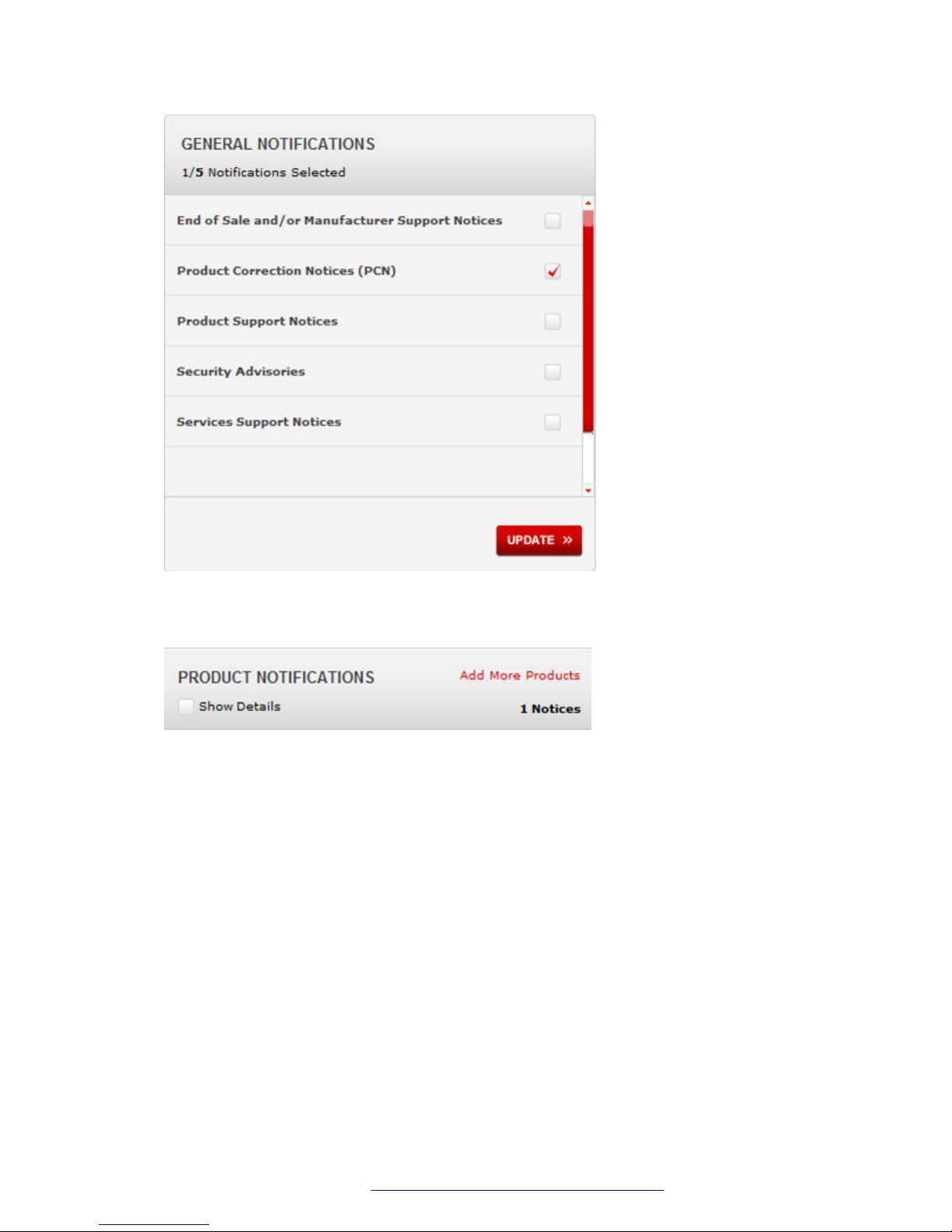
Related Resources
6. Click OK.
7. In the PRODUCT NOTIFICATIONS area, click Add More Products.
8. Scroll through the list, and then select the product name.
9. Select a release version.
10. Select the check box next to the required documentation types.
September 2016 Quick Start Configuration 52
Comments on this document? [email protected]
Page 53
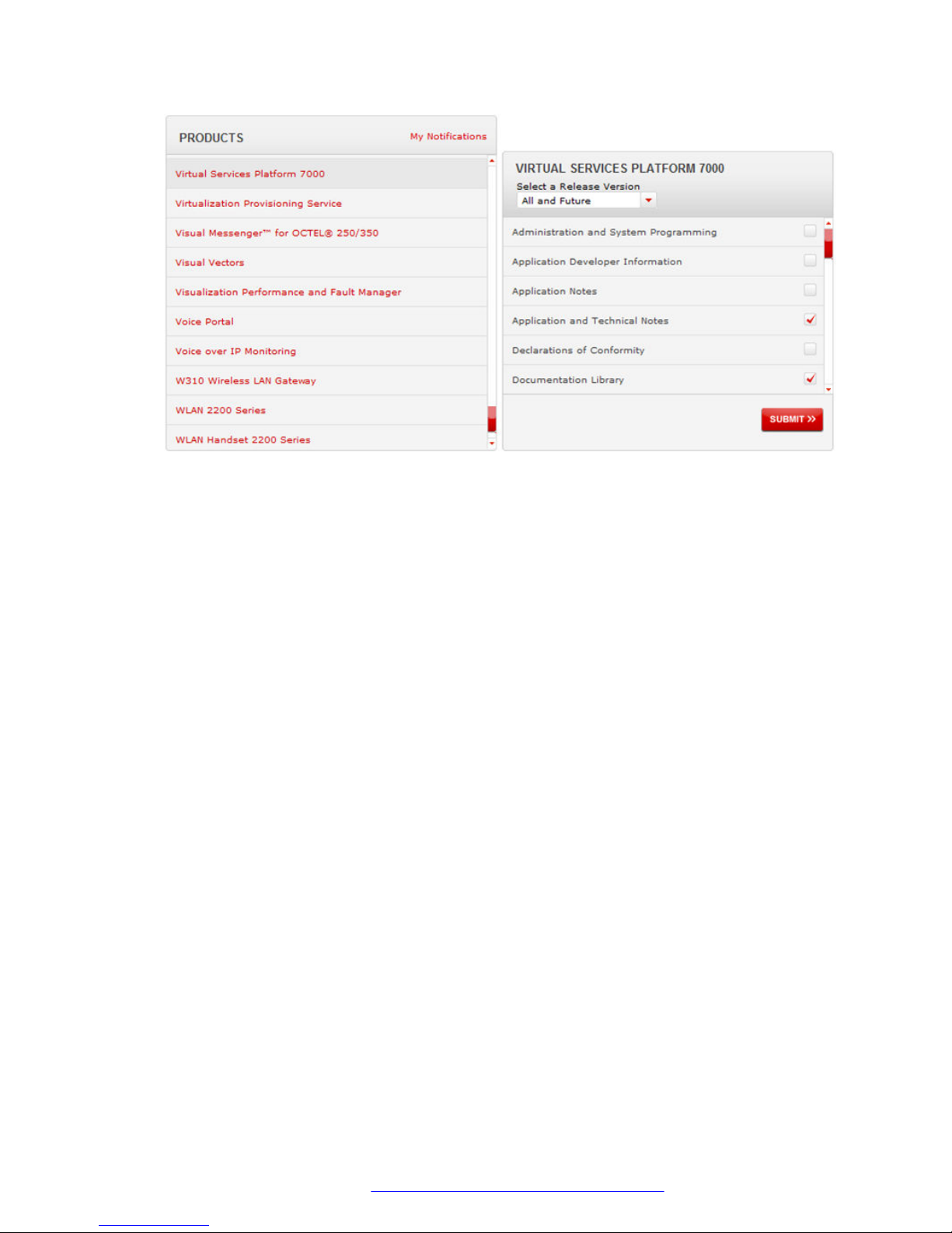
11. Click Submit.
Subscribing to e-notifications
September 2016 Quick Start Configuration 53
Comments on this document? [email protected]
 Loading...