

Avanti SHARK L AECO Original Instructions Manual
AVANTI SERVICE LIFT
User’s, Installation and Maintenance Manual
Model SHARK L AECO
Original instructions
AT00016288 Shark L AECO EN update.indd 1 11/14/2018 4:02:34 PM
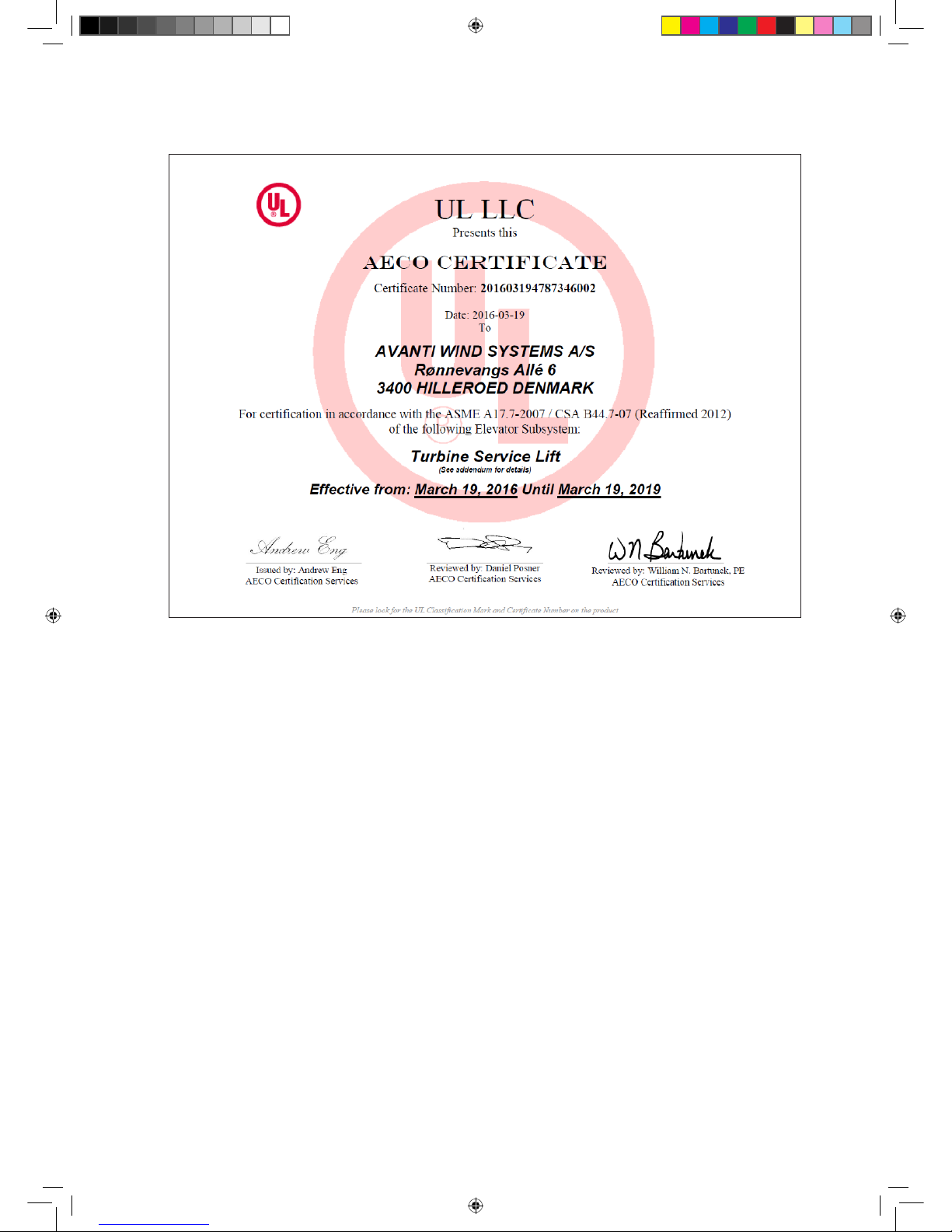
AECO certificate for Shark L equipped with M508 hoist:
AT00016288 Shark L AECO EN update.indd 2 11/14/2018 4:02:34 PM
Manufactured Under Process Patent NO.8,499,896.
® Registered in Europe
Date of publication:
1st Edition: October 2018
Revision 1: 26/10/2018
Manufacturer:
AVANTI Wind Systems A/S
Rønnevangs Allé 6
3400 Hillerød Denmark
P: +45 4824 9024
F: +45 4824 9124
E: info@avanti-online.com
I: www.avanti-online.com
Sales & Service:
Australia Avanti Wind Systems P/L P: +61 (0) 439 349 350
China Avanti Wind Systems P: +86 21 5785 8811
Denmark Avanti Wind Systems A/S P: +45 4824 9024
Germany Avanti Wind Systems GmbH P: +49 (0) 41 21-7 88 85 – 0
Spain Avanti Wind Systems SL P: +34 976 149 524
UK Avanti Wind Systems Limited P: +44 0 1254 399923
USA Avanti Wind Systems, Inc P: +1 (262) 641-9101
India Avanti Wind Systems India (P) Ltd P: +91 95 00 173 492
Brazil Avanti Brasil Sistema Eólicos LTDA P: +55 85 9 9955-0090
AT00016288 Shark L AECO EN update.indd 3 11/14/2018 4:02:34 PM

4
AVANTI Service Lift for Wind Turbines
Page
User’s manual
1. Limited warranty ..................................................... 6
2. Introduction ......................................................... 7
2.1 Symbols .........................................................7
2.2 Terms and definitions .................................................7
3. Cautions ........................................................... 8
4. Instructions ......................................................... 9
5. Description of equipment............................................... 10
5.1 Purpose ........................................................ 10
5.2 Function........................................................ 10
5.3 Service lift models ................................................. 10
5.4 Temperature ..................................................... 10
5.5 Accessories ..................................................... 10
5.6 Components..................................................... 11
5.6.1 Cabin overview .............................................. 11
5.6.2 Technical data for the service lift SHARK L ............................ 12
5.6.3 Drive system, fall arrest device and controls ........................... 13
5.7 Cabin safety devices ............................................... 14
5.7.1 Electromagnetic motor brake .................................... 14
5.7.2 EMERGENCY STOP ........................................... 14
5.7.3 EMERGENCY STOP fixed (Optional) ................................ 14
5.7.4 Automatic operation switch ...................................... 14
5.7.5 Overload limiter .............................................. 14
5.7.6 Fall arrest device ............................................. 14
5.7.7 Yellow flash (Optional).......................................... 14
5.7.8 Emergency light (Optional) ....................................... 14
5.7.9 Door stop switch ............................................. 15
5.7.9.1 Sliding door: ........................................... 15
5.7.10 Trapped-Key interlock system (Optional): ............................. 15
5.7.11 Limit stop switch ............................................. 15
5.7.11.1 Top limit stop switch ..................................... 15
5.7.11.2 EMERGENCY top limit switch............................... 15
5.7.11.3 Bottom obstruction detection device .......................... 15
5.7.11.4 Top obstruction detection device ............................ 15
5.8 Safety devices for fences with doors (optional) .............................. 15
5.8.1 Guard Locking System .......................................... 15
5.8.2 Trapped-key Interlock System ..................................... 16
5.9 Slack rope sensor ................................................. 16
5.10 Anchor points .................................................... 16
6. Daily inspection by the supervisor ........................................ 17
6.1 Service lift ...................................................... 17
6.2 Operating area ................................................... 17
6.3 Control functions ..................................................17
6.4 Automatic operation test ............................................. 18
6.5 Fall arrest device .................................................. 18
6.6 Wires ropes ..................................................... 18
6.7 Wires ropes after an unusual event ...................................... 19
7. Use of the service lift .................................................. 20
7.1 Prohibited uses ................................................... 20
7.2 Entry and exit .................................................... 20
7.3 Stop/EMERGENCY STOP ............................................20
7.4 Normal operation .................................................. 20
7.5 Automatic operation ................................................ 20
7.6 Overload limiter ...................................................21
7.7 Override of the bottom obstruction detection device .......................... 21
8. Manual operation (EMERGENCY) . . . . . . . . . . . . . . . . . . . . . . . . . . . . . . . . . . . . . . . . . 22
8.1 EMERGENCY descent .............................................. 22
9. Fall arrest device ASL508 ............................................... 23
Contents
AT00016288 Shark L AECO EN update.indd 4 11/14/2018 4:02:35 PM

5
User’s Manual
10. Troubleshooting ..................................................... 24
11. Out of service ....................................................... 27
12. Removing wires for replacement ......................................... 27
12.1 Parking the service lift .............................................. 27
12.2 Wire rope ends ................................................... 27
12.3 Removing the traction wire rope ........................................ 27
12.4 Removing the safety wire rope .........................................27
13. Maintenance........................................................ 27
13.1 Recommended planning .............................................27
13.2 Alternative planning ................................................ 28
13.3 Cautions ....................................................... 28
13.4 Annual inspection . . . . . . . . . . . . . . . . . . . . . . . . . . . . . . . . . . . . . . . . . . . . . . . . . 28
13.4.1 Cabin .....................................................28
13.4.2 Traction hoist ................................................ 29
13.4.3 Fall arrest device ............................................. 29
13.4.4 Traction, safety and guiding wire ropes............................... 30
13.4.5 Electrical cables .............................................. 30
13.4.6 Overload check and adjustment ................................... 30
13.4.7 Information signs and documents .................................. 30
13.5 Repairs ........................................................ 30
13.6 Ordering spare parts................................................ 31
14. Transport and storage ................................................. 31
Installation manual
1. Fitting of wires........................................................ 32
1.1 Tower top....................................................... 32
1.2 Wire ropes positioning measurements ................................... 33
1.3 Securing the guide wire ropes - ground level................................ 34
1.3.1 Method 1: Wedge anchor ........................................ 34
1.3.2 Method 2: Tripod .............................................. 34
1.3.3 Method 3: Graduated tensioner .................................... 35
1.3.4 Tensioning the guide wire ropes Ø0.47 in (12 mm) ........................ 35
1.4 Electrical connections ............................................... 35
1.4.1 Power supply ................................................ 35
1.4.2 Supply cable ................................................. 36
1.4.3 Power connection ............................................. 36
1.4.4 Bottom platform control box ...................................... 36
1.5 Installation of traction and safety wire ropes through lift ........................ 37
1.6 Securing the traction and safety wire rope ................................. 38
1.7 Wire rope fix alignment .............................................. 39
1.8 Adjustment of the safe-zone plates ...................................... 40
1.9 Adjustment of top limit device (bar) ...................................... 40
2. Danger zone! sticker ................................................... 40
3. Disassembling........................................................ 40
4. Inspection before initial use .............................................. 40
Appendix A: Regulation of overload limiter ..................................... 41
Appendix B: Safety measures............................................... 42
Appendix C: Inspection Checklist ............................................ 44
Appendix D: AVANTI lift anchor.............................................. 48
Appendix E: Inspection log sheet ............................................ 52
Appendix F: Stomp-test Instruction........................................... 55
AT00016288 Shark L AECO EN update.indd 5 11/14/2018 4:02:35 PM

6
AVANTI Service Lift for Wind Turbines
1)
Avanti service lift (“Product”)
Avanti Wind Systems A/S warrants that commencing from the date of shipment to the
Customer and continuing for a period of the
longer of 365 days thereafter, or the period set
forth in the standard AVANTI warranty, the
Product1) described in this Manual will be free
from defects in material and workmanship
under normal use and service when installed
and operated in accordance with the provisions
of this Manual.
This warranty is made only to the original user
of the Product. The sole and exclusive remedy
and the entire liability of Avanti under this
limited warranty, shall be, at the option of
Avanti, a replacement of the Product (including
incidental and freight charges paid by the
Customer) with a similar new or reconditioned
Product of equivalent value, or a refund of the
purchase price if the Product is returned to
Avanti, freight and insurance prepaid. The
obligations of Avanti are expressly conditioned
upon return of the Product in strict accordance
with the return procedures of Avanti.
This warranty does not apply if the Product (i)
has been altered without the authorization of
Avanti or its authorized representative; (ii) has
not been installed, operated, repaired, or
maintained in accordance with this Manual or
other instructions from Avanti; (iii) has been
subjected to abuse, neglect, casualty, or
negligence; (iv) has been furnished by Avanti to
Customer without charge; or (v) has been sold
on an “AS-IS” basis.
Except as specifically set forth in this Limited
Warranty,
ALL EXPRESS OR IMPLIED CONDITIONS,
REPRESENTATIONS AND WARRANTIES,
INCLUDING, BUT NOT LIMITED TO, ANY
IMPLIED WARRANTY OR CONDITION OF
MERCHANTABILITY, FITNESS FOR A PARTICULAR PURPOSE, NON-INFRINGEMENT,
SATISFACTORY QUALITY, COURSE OF DEALING, LAW, USAGE OR TRADE PRACTICE ARE
HEREBY EXCLUDED TO THE MAXIMUM
EXTENT PERMITTED BY APPLICABLE LAW
AND ARE EXPRESSLY DISCLAIMED BY
AVANTI. IF, PURSUANT TO ANY APPLICABLE
LAW, TO THE EXTENT AN IMPLIED WARRANTY CANNOT BE EXCLUDED AS PROVIDED IN
THIS LIMITED WARRANTY, ANY IMPLIED
WARRANTY IS LIMITED IN TIME TO THE SAME
DURATION AS THE EXPRESS WARRANTY
PERIOD SET FORTH ABOVE. BECAUSE SOME
STATES DO NOT PERMIT LIMITATIONS ON
THE DURATION OF IMPLIED WARRANTIES,
THIS MAY NOT APPLY TO A GIVEN CUSTOMER. THIS LIMITED WARRANTY GIVES CUSTOMER SPECIFIC LEGAL RIGHTS, AND
CUSTOMER MAY HAVE OTHER LEGAL
RIGHTS UNDER APPLICABLE LAWS.
This disclaimer shall apply even if the express
warranty fails of its essential purpose.
In any cases of dispute the English original shall
be taken as authoritative.
1. Limited Warranty
AT00016288 Shark L AECO EN update.indd 6 11/14/2018 4:02:35 PM
7
STOP
!
!
User’s Manual
2. Introduction
Only trained people may use this lift.
This manual must be available to staff at all times during installation, maintenance and operation.
Additional copies are available from the manufacturer upon request.
This manual, including, but not limited to, measurements, procedures, components, descriptions,
instructions, recommendations and requirements, is subject to change without prior notice. Please
check Avanti website/manuals for the latest revisions of the manuals.
Any additional cost related to or arising from any changes in the manuals does not entitle Customer to
any form of compensation or other legal remedies.
The pictures and sketches in this manual may not reflect the product aesthetics, colours,
arrangement precisely. This has no impact on the function or safety.
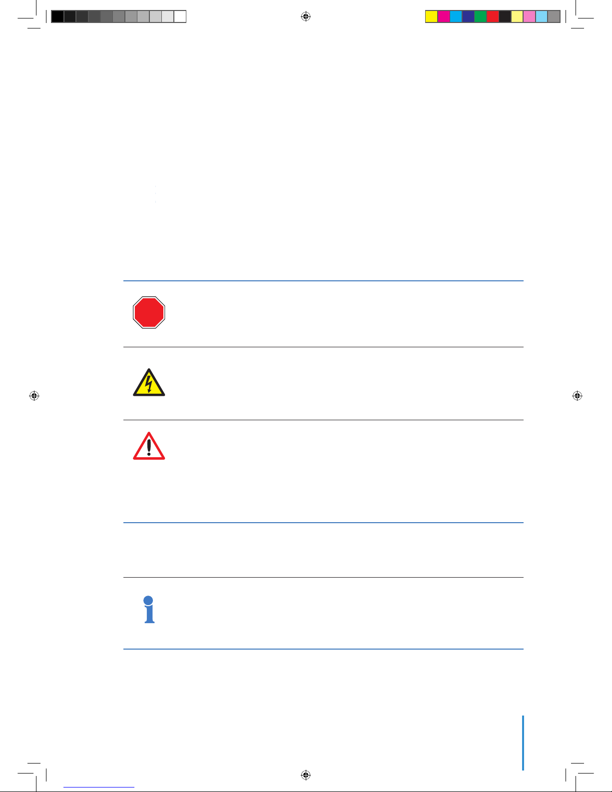
2.1 Symbols
Symbol Signal word Meaning Possible injury if not observed
Safety instructions
DANGER!
IMMEDIATE or
possibly imminent
danger:
Death or severe injury!
DANGER!
IMMEDIATE or
possibly imminent
danger of hazardous
voltage:
Death or severe injury!
CAUTION! Potentially hazardous
situation:
Light injury or material damage.
Additional instructions
ATTENTION!
Potentially dangerous
situation:
Damage to equipment or workplace
IMPORTANT!
Useful tips for optimum
working procedure
None
Order
Reference to written
specification/documentation
AT00016288 Shark L AECO EN update.indd 7 11/14/2018 4:02:35 PM
8
AVANTI Service Lift for Wind Turbines
3. Cautions
Use and daily inspection of the service lift shall only be
performed by person who has gone through the relevant
training associated with the Avanti service lift use and daily
inspection and is in possession of a valid (non expired)
certificate for the task. Installation and maintenance of the
service lift shall only be performed by Certified technicians.
The personnel must be at least 18 years of age.
The staff must be familiar with the relevant accident prevention instructions and must have received proper training in
these.
Personnel are obliged to read and understand this manual.
Personnel shall wear PPE (safety helmet, full body harness, shock absorber, lanyard and slider) at all times.
A copy of the Manual must be handed out to the personnel
and must always be available for reference.
If more than one person is entrusted with one of the above
tasks, the employer shall appoint a supervisor in charge of
the operation.
Electrical connection of the system must be made in accordance with EN 60204-1.
Self-locking nuts must be used at all times. The screw must
extend from the nut by at least half of the thread diameter.
The nut may not be used once it has become possible to
loosen by hand!
If any damage or faults are found during operation, or if
circumstances arise which may jeopardize safety: immediately interrupt the work in progress and notify the supervisor
or employer! All tests/repairs of electrical installations may
only be performed by a certified technician.
All repairs to the traction, braking and supporting sys- tems
may only be performed by a certified technician.
If any supporting parts are repaired or replaced,
If any supporting parts are repaired or replaced, the operational safety of the system must be tested and verified by a
certified technician.
Only original fault-free parts may be used.
Use of non-original parts will render the manufacturer’s warranty void and any type approval invalid.
No modification, extension or reconstruction of the service
lift is allowed without the manufacturer’s prior written consent.
No warranty is provided against damage resulting from
reconstruction or modification of equipment or use of nonoriginal parts which are not approved by the manufacturer.
Before using the service lift an inspection by the authorized
inspection organisation must be carried out. The service lift
must be inspected at least once a year by a certified technician. In case of high operating frequency or severe conditions of use, more frequent inspection is required.
Service lift is designed for a lifetime of 20 years with an
operating frequency of approximately 12.5 h/year (250 h in
total).
Service lift may not be used by persons who are under the
influence of alcohol or drugs which may jeopardize working
safety.
Service lift lift shall not be used in case of fire in the tower.
Service lift shall ONLY be used when the turbine is not
generating power.
All wind farm site specific rules must be followed. Service
lift shall not be used during inclement weather, including
wind speeds over 25 m/s (55.5 mph).
AECO service lift personnel shall be equipped with a wired
or wireless two way communication device connected to a
location staffed by authorized personnel.
Avoid injury – follow all instructions!
Owner must verify the need for third
par ty service lift inspections with the local
authority and comply with the standards
specified.
Terms Definitions
Certified technician
Person who has gone through the relevant training associated with the scheduled task from Avanti or
from a certified trainer and is in possession of a valid (non expired) certificate for the task.
User
Person who has gone through the relevant training associated with the Avanti service lift use and daily
inspection and is in possession of a valid (non expired) certificate for the task.
Manual descent
Action performed to descend the lift at a controlled speed without power supply by manually opening
the hoist electromagnetic brake. (Also manual no-power descent)
2.2 Terms and definitions
Equivalences of terminology
British English terms North American English terms
Service lift / cabin
Elevator
AT00016288 Shark L AECO EN update.indd 8 11/14/2018 4:02:35 PM

9
User’s Manual
a) Before and after using, check all parts for proper
function and damage to component parts. Do not use a
damaged or improperly functioning product.
b) Any parts that have been exposed to excessive heat,
as in the case of fire, should be immediately removed
from service and destroyed due to loss of structural
strength.
c) Do not permit oil, grease, or slippery material to accu
mulate on climbing or gripping surfaces.
d) Planks and stages are designed with rated working
loads of 533 lbs (240 kg). The total combined weight of
each worker and all materials should not exceed the
rated working load. Do not overload.
e) Erect the plank or platform so that the working or
standing surface is level.
f) Support plank or platform ends by stirrups, scaffold
bearer members, trusses or other equipment intended
for this purpose.
g) Use guardrails, midrails, and toe boards as required
by local, state, and federal regulations. Their use is
recommended in all cases.
h) Do not allow unstable objects, such as barrels, boxes,
loose brick, tools, and debris to accumulate on the work
surface.
i) Do not use a ladder or other device to gain greater
heights.
j) Never climb onto a stage from a ladder unless both
the stage and the ladder are secured from movement in
all directions.
k) Do not ride on top of a moving work cage. Tools,
materials, and equipment should not be stored on
planks or platforms that are being moved.
l) Do not apply impact loads to any parts.
m) Do not use acids or other corrosive sub- stances on
a plank or platform without consulting the plank or
platform manufacturer for specific instructions.
n) Before using, refer to manufacturer’s instructions.
4. Instructions
AT00016288 Shark L AECO EN update.indd 9 11/14/2018 4:02:35 PM

10
AVANTI Service Lift for Wind Turbines
The service lift purpose is to transport persons
plus their tools and equipment to the most convenient height for performing work in wind turbine
generators (WTG).
Its use is limited to authorized users.
The access to the WTG and consequently to the
service lift is controlled and forbidden to public
access.
The service lift is used primarily to transport
technicians, their tools and spare parts from the
bottom platform (or lowest accessible point) to the
top platform (or highest accessible point).
It is also used to access intermediate platforms
where inspection and service of WTG connecting
bolts and other equipment is made.
5.2 Function
The service lift uses a traction hoist to ascend and
descend a wire rope suspended from a beam
within the wind turbine along a defined travel path.
A fall arrest device is attached to the service lift and
ascends and descends with it on a second
suspended wire rope, called the safety wire rope.
Ascent and descent of the service lift is controlled
from within the service lift via a manual mode or
from outside the service lift in an automatic send
mode.
An overload limiter prevents ascent of the service
lift in the event of an overload of the traction hoist.
Two tensioned wire ropes act as guiding means
along the travel path of the service lift.
5.3 Service lift models
This User’s Manual and Installation Manual
describe the following models:
• SHARK L AECO sliding door with 533 Lbs
(240kg) lifting capacity, AECO control box,
traveling cable (optional) and slack rope sensor.
5.4 Temperature
Operating temperature
5ºF to +140ºF (-15ºC to +60ºC).
Survival temperature
-13ºF to +176ºF (-25ºC to +80ºC).
Low temperature kit is also available. Operational
temperature for low temperature kit
-13ºF to +104ºF (-25ºC to +40ºC).
5.5 Accessories
In order to fulfil the essential health and safety
requirements from the regulations the design of
the wind turbine and its components shall complement the safety systems supplied on the service
lift making the ensemble safe as a whole.
A detailed evaluation of compliance to the EHSR
and a risk assessment shall be completed. Avanti
shall verify the compliance to such requirements
prior to installation. Systems that may be considered to complement the service lifts are:
5.5.1 Fences & guards
The service lift hole must be adequately protected
to prevent people from falling or being injured by
the movement of the service lift. The fences and
guards design shall comply with the relevant
standards and local regulations.
5.5.2 Safety system for landing access doors
The service lift hole must be adequately protected
to prevent risk of falling. When the service lift is not
at the landing, access doors shall not be able to
open. Such function may be achieved by using
interlock systems on access doors linked to the
position of the service lift.
5. Description of equipment
5.1 Purpose
AT00016288 Shark L AECO EN update.indd 10 11/14/2018 4:02:35 PM
11
User’s Manual
5.6 Components
5.6.1 Cabin overview
Fig. 1 SHARK L sliding door
1 Top hatch
2 Fall arrest device
3 Cabin control box
4 Anchor points
5 Interlock switch
6 Trapped-key switch
7 Pendant control
8 Full sliding door
9 Bottom obstruction detection device
10 Traction hoist
11 Top obstruction detection device
3
4
5
6
7
8
1
2
3
11
10
2
3
4
7
9
5
1
6
8
AT00016288 Shark L AECO EN update.indd 11 11/14/2018 4:02:41 PM
12
AVANTI Service Lift for Wind Turbines
5.6.2 Technical data for the service lift SHARK L
Fig. 2 Dimensions, sliding door
4
5
6
7
2
9
4
0
2
0
9
9
1
9
8
8
2
4
8
0
1150
960
6
6
1
3
8
0
AT00016288 Shark L AECO EN update.indd 12 11/14/2018 4:02:42 PM
13
8
7
9
10
11
12
13
5
6
14
15
16
1
2
3
4
M508
User’s Manual
5.6.3 Drive system, fall arrest device and controls
Fig. 3 Traction hoist
Fig. 4 Fall arrest device
Table 1. Traction hoist
Table 2. Fall arrest device
1 Insertion point for
brake lever
2 Motor
3 Wire rope traction
w/overload protection
4 Drive system/gearbox
5 Unlock lever
6 Lock lever
7 ASL Lamp
8 Automatic/Manual
9 Ready lamp
10 Override switch bottom
obstruction detection device
11 Main switch
12 Hour counter
13 Platform level light (optional)
14 EMERGENCY STOP button
15 UP
16 DOWN
Fig. 5 Electrical control box
For M508
ASL508
Fig. 6 a
Pendant control
Hoist
Lifting
capacity
Wire rope speed Effect
Rated
current
Traction wire
rope Ø
Unit weight
approx.
Traction hoist type Lbs (Kg) Feet/min (m/min) kW A in (mm) Lbs (Kg)
1)
M508/400V 60Hz
1100 (500) 66 (21) 1.8 4.9 0.33 (8.4) 110 (50)
M508/480V 60Hz
1100 (500) 66 (21) 1.8 4.1 0.33 (8.4) 110 (50)
1) Weight without wire rope.
Installed with a properly sized, listed GFCI in accordance with NFPA 70 or CSA 22.1 as required.
Fall arrest device Lifting capacity
To max.
wire rope speed
Traction
wire rope Ø
Unit weight
approx.
Fall arrest type Lbs (kg) Feet/min (m/min) in (mm) Lbs (kg)
ASL508
1100 (500) 105 (30) 0.33 (8.4) 15.4 (7)
Wire rope type
Wire rope
diameter
Surface
treatment
Mark/
feature
Min. break
resistance
Attached
with
Anchoring
Tighten
to
Guiding wire rope
0.47 in (12mm) galvanised - 55 kN Shackle,2t
Min. every
115 ft (35 m)
2 to 4 kN
M508/ASL508
0.33 in, 5x19
(8.4mm, 5x19)
galvanised none 55 kN
2 t shackle,
Form C
- -
Table 3. Drive wire, safety wire and guide wire
AT00016288 Shark L AECO EN update.indd 13 11/14/2018 4:02:44 PM
14
AVANTI Service Lift for Wind Turbines
5.7 Service lift safety devices
5.7.1 Electromagnetic motor brake
Electromagnetic spring-loaded brake which
engages automatically
– on releasing the up/down push button and
– following a power failure.
5.7.2 EMERGENCY STOP
When the red EMERGENCY STOP (pendant
control) switch is pushed in an emergency, all
control is interrupted. After remedying the fault,
control is reactivated by turning the switch clockwise, until it pops out again.
5.7.3 EMERGENCY STOP fixed (optional)
Only in service lifts with an AUTOMATIC function
installed. A backup switch to the pendant control
EMERGENCY STOP switch is situated on one of
the side panels inside the lift (Fig. 8).
5.7.4 Automatic operation switch
A switch situated inside the pendant control
holder. It prevents the lift from being controlled
from the inside when the control is in automatic
mode.
5.7.5 Overload limiter
The overload limiter is built into the wire rope
traction system and will prevent upward travel in
the event of an overload. A warning signal
(buzzer) is triggered which will stop only when the
cause of the overload has been removed.
Possible reasons for activation of the limiter:
- The service lift is overloaded or
- the service lift encounters an obstacle during
upward travel.
Operator intervention:
- Reduce the load to below the overload limit, or
- lower the lift until it is free of the obstacle and
remove the obstacle before using the lift again.
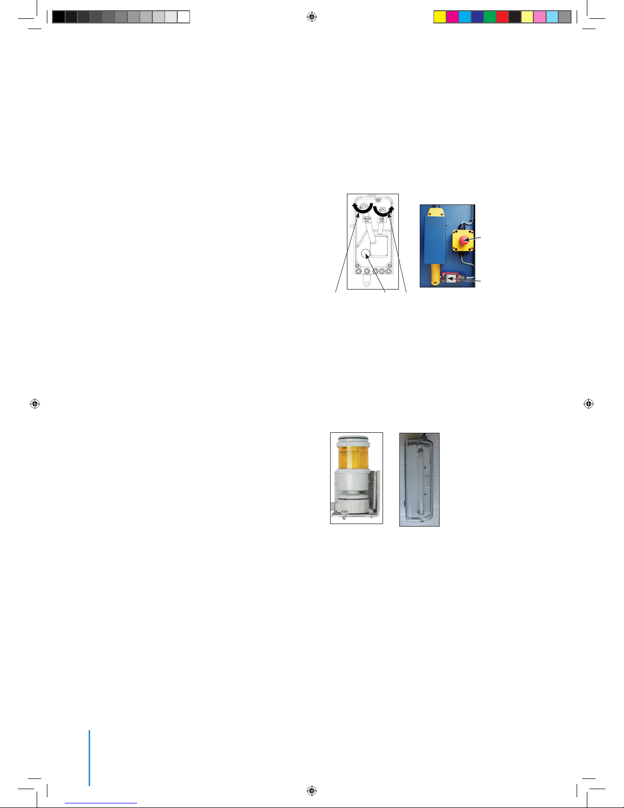
5.7.6 Fall arrest device
Service lifts for personnel transportation must be
equipped with a fall arrest device which will
prevent the load from falling.
Fall arrest device type ASL.The fall arrest devices
ASL are opened manually (Fig. 7).
The speed of the safety wire rope passing
through the device is continuously monitored,
and the jaws automatically close in the event of
sudden excessive speed.
This protects the service lift from
a) Traction wire rope breaks and
b) Hoist failures.
The fall arrest device can also be engaged
manually in an emergency by pressing the
Emergency stop button. The window is used to
monitor the function of the centrifugal force
mechanism during operation.
5.7.7 Yellow flash (optional)
An optional set of flashes can be mounted on the
top and at the base of the lift. The flashes indicate
when the lift is in movement (Fig 9a).
4.7.8 Emergency light (optional)
An emergency light can be installed to provide
illumination inside the lift with and without electric
supply. The operation modes can be selected
by means of a switch (Fig. 9b).
Fig. 7
Fall arrest device
ASL508
LockedUnlocked
Window
Fig. 8
Emergency stop
and automatic
operation switch
Fig. 9a
Fixed
Emergency
stop button
Fig. 9b
Automatic
operation
switch
AT00016288 Shark L AECO EN update.indd 14 11/14/2018 4:02:44 PM
15
!
1
2
3
User’s Manual
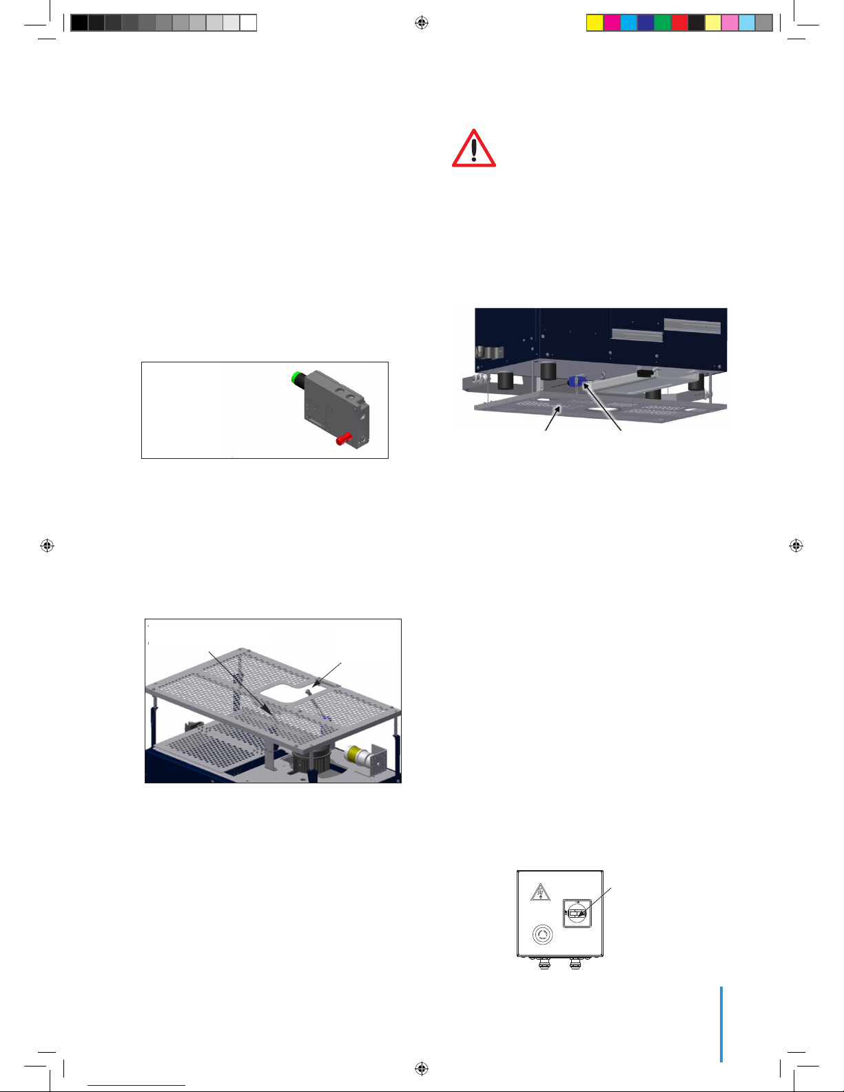
5.7.9 Door stop switch
5.7.9.1 Sliding door:
The sliding door is closed by pushing the actuator into
the door guard locking switch (Fig. 10). The switch is
unlocked by pushing the green button if the cabin is
located at a height corresponding to a platform. In
case of an emergency evacuation between platforms,
the interlock is unlocked by pushing its emergency
release red button from outside the cabin as well as
using an M5 triangular key from inside the cabin.
5.7.10 Trapped-key interlock system (optional):
Control is interrupted by turning the trapped-key
switch to OFF. The key can then be removed. The key
allows the user to open the platform fence doors. See
the Trapped-Key Interlock System Manual for further
information.
5.7.11 Limit stop switch
5.7.11.1 Top limit stop switch
At the top of the cabin frame a top obstruction
detection device switch (works as a top limit stop
switch) will stop upward travel when activated (Fig. 11).
Downward travel will still be possible. A top stop bar
which activates the top obstruction detection device
switch is installed below the traction wire rope
attachment.
ATTENTION!
When the top obstruction detection
device switch is engaged, activate the
DOWN switch until the top obstruction
detection device switch is released.
5.7.12.2 EMERGENCY top limit switch
Deactivates control if the top obstruction detection
device switch fails (Fig. 11). Manual downward travel is
possible.
CAUTION!
Do not use the service lift until the top
limit stop switch fault has been rectified.
5.7.11.3 Bottom obstruction detection device
The bottom obstruction detection device switch (Fig.
12) stops downward travel if the service lift
encounters an obstacle or t o uches the ground.
Upward travel will be possible, for instance to remove
the obstacle. In order to put the service lift on the
ground, the contact plate’s operation can be bypassed
with the key switch in the control box.
5.7.11.4 Top obstruction detection device
The top obstruction detection device switch stops
upward travel in case the service lift:
- Type 1: encounters an obstacle.
- Type 2: the switch also works as a top limit stop
switch. A top stop end bar is installed bellow the
guiding wire rope attachment and activates the top
obstruction detection device switch.
Downward travel will be possible, for example, to
remove the obstacle.
5.8 Safety devices for fences with
doors (optional)
Safety devices for fences include devices to prevent
people from accessing the service lift area, unless the
service lift is safe to be accessed. The device also
guarantees that the service lift does not when the
protective fence doors are open. There are two types
of safety devices for fences:
5.8.1 Guard Locking System
The Guard Locking System uses a system of security
locking switches installed on the fences. Another
position switch detects the correct position of the
service lift on the protected platform. The service lift
cannot operate until all the protected fences are
closed and locked.
Fig. 10
1 Green push button
2 Emergency release red push button
3 Emergency release M5 triangular key
Top obstruction detection devide
switch
Bottom obstruction
detection device
Bottom obstruction
detection device switch
Main Switch Disconnector
Emergency top
limit switch
Fig. 13
AT00016288 Shark L AECO EN update.indd 15 11/14/2018 4:02:45 PM
 Loading...